1 ip security. 2 ip security overview we have considered some application specific security...
Post on 19-Dec-2015
220 views
TRANSCRIPT
1
IP Security
2
IP Security Overview
• We have considered some application specific security mechanisms– eg. S/MIME, PGP, Kerberos, SSL/HTTPS
• However there are security concerns that cut across protocol layers
• Would like security implemented by the network for all applications

33
Security versus OSI & TCP/IP Model
Physical
Network
Data Link
Transport
Session
Presentation
Application
Physical
Internet
Data Link
Transport
Presentation
Application
Application
OSI TCP/IP
Cryptography
Protocol
Applications
Security

44
Security Flows
CryptographyAlgorithm:Symmetric, Asymmetric (i.e.:Cipher, DES, AES)
Protocol
Applications
Protocol:SSL, TLS, IPSec
Applications:Web, email, any application use security mechanism
* This approach is totally under my knowledge and experience, is not a standard, just to understand the layer concept.

5
IP Security Overview
IPSec is not a single protocol. Instead, IPSec provides a set of security algorithms plus a general framework that allows a pair of communicating entities to use whichever algorithms provide security appropriate for the communication.

6
TCP/IP Example

7
What is IPSec?
• IP Security is a set of protocols and standards to support the securing of data at the IP layer. IPSec is a framework, not an implementation.
• Supports authentication and encryption of traffic.– Certifies the originator of the packet.– Protects the data from interception and tampering
while in transit.

8
IPSec
• general IP Security mechanisms
• provides– authentication– confidentiality– key management
• applicable to use over LANs, across public & private WANs, & for the Internet
9
IP Security Overview
• Applications of IPSec– Secure branch office connectivity over the
Internet– Secure remote access over the Internet– Establsihing extranet and intranet connectivity
with partners– Enhancing electronic commerce security

10
IPSec Uses

11
Benefits of IPSec
• in a firewall/router provides strong security to all traffic crossing the perimeter
• is resistant to bypass
• is below transport layer, hence transparent to applications
• can be transparent to end users
• can provide security for individual users if desired

12
IP Security Architecture
• specification is quite complex
• defined in numerous RFC’s– incl. RFC 2401/2402/2406/2408– many others, grouped by category
• mandatory in IPv6, optional in IPv4

13
IPSec Services
• Access control
• Connectionless integrity
• Data origin authentication
• Rejection of replayed packets– a form of partial sequence integrity
• Confidentiality (encryption)
• Limited traffic flow confidentiality

14
Why do we want to use IPSec?

15
Why do we want to use IPSec?
• Secure our network
• Transparent operation– IPSec allows us to secure any IP based protocol
transparent to the application. – Support for legacy software which is inherently insecure
(telnet,ftp).– An alternative mechanism to implementing application
level security such as using SSL.
• Widest industry support e.g. Cisco, Microsoft, Network Associates, CheckPoint Software, Bay Networks, etc.
• IETF standard – Will be mandatory in IPv6

16
Why not use IPSec?

17
Why not use IPSec?
• Processor overhead to encrypt & verify each packet can be great.
• Added complexity in network design.

18
IPSec
Data Protocols
IKE ESP AH
IPsec can be used for:- two hosts- two security gateways- a host and security gateway
Control Protocols
IPSec Diagram Structure
IKE – Internet Key Exchange
ESP – Encapsulating Security Payload
AH – Authentication Header

19
IKE (ISAKMP)
Connection Security
DES 3DES MD5
Key Exchange(Oakley, SKEME) Authentication
Diffle Hellman EncryptionDigital
SignatureSharedSecret
Message Integrity
Message Integrity
SHA-1
IPSec Diagram Structure

20
Data Protocols
ESP
Null DES MD5
AH
Encryption Integrity
SHA-13DES MD5
Integrity
SHA-1
IPSec Diagram Structure
21
IPSec Modes
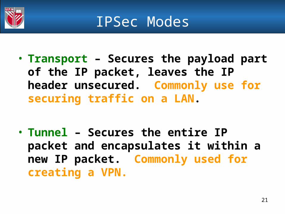
• Transport – Secures the payload part of the IP packet, leaves the IP header unsecured. Commonly use for securing traffic on a LAN.
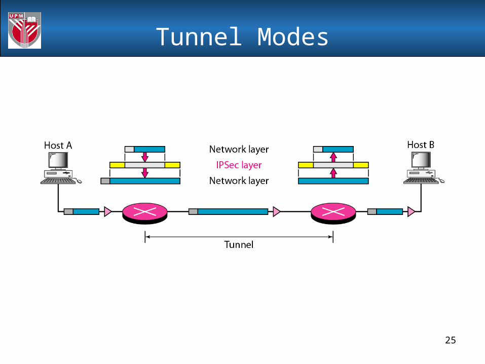
• Tunnel – Secures the entire IP packet and encapsulates it within a new IP packet. Commonly used for creating a VPN.

22
IPSec Modes

23
Transport Modes

24
IPSec in the transport mode does not protect the IP header; it only protects
the information coming from the transport layer.
Note
25
Tunnel Modes
26
Tunnel Modes
IPSec in tunnel mode protects the original IP header.
Note

27
IPSec protocols – AH protocol
• AH - Authentication Header– Defined in RFC 1826– Integrity: Yes, including IP header– Authentication: Yes– Non-repudiation: Depends on cryptography algorithm.– Encryption: No– Replay Protection: Yes
IP Header AH Header Payload (TCP, UDP, etc)
IP Header AH Header Payload (TCP. UDP,etc)IP Header
Transport Packet layout
Tunnel Packet layout

28
AH protocol in Transport Mode

29
AH & ESP

30
The AH Protocol provides source authentication and data integrity,
but not privacy.
Note

31
End-to-end versus End-to-Intermediate Authentication

32
IPSec protocols – ESP protocol
• ESP – Encapsulating Security Payload – Defined in RFC 1827– Integrity: Yes– Authentication: Depends on cryptography algorithm.– Non-repudiation: No– Encryption: Yes– Replay Protection: Yes
IP Header ESP Header Payload (TCP, UDP, etc)
IP Header ESP Header Payload (TCP. UDP,etc)IP Header
Transport Packet layout
Tunnel Packet layout
Unencrypted Encrypted

33
ESP protocol in Transport Mode

34
ESP provides source authentication, data integrity, and privacy.
Note

35
What protocol to use?
• Differences between AH and ESP:– ESP provides encryption, AH does not.– AH provides integrity of the IP header, ESP does not.– AH can provide non-repudiation. ESP does not.
• However, we don’t have to choose since both protocols can be used in together.
• Why have two protocols?– Some countries have strict laws on encryption. If you can’t
use encryption in those countries, AH still provides good security mechanisms. Two protocols ensures wide acceptance of IPSec on the Internet.

36
Security Associations• One of the most important concepts in IPSec is called a
Security Association (SA). Defined in RFC 1825.
• SAs are the combination of a given Security Parameter Index (SPI) and Destination Address.
• SAs are one way. A minimum of two SAs are required for a single IPSec connection.
• SAs contain parameters including:– Authentication algorithm and algorithm mode – Encryption algorithm and algorithm mode – Key(s) used with the authentication/encryption algorithm(s) – Lifetime of the key– Lifetime of the SA– Source Address(es) of the SA– Sensitivity level (ie Secret or Unclassified)

37
Example
• A security is a very complex set of pieces of information. However, we can show the simplest case in which Alice wants to have an association with Bob for use in a two-way communication.
• Alice can have an outbound association (for datagrams to Bob) and an inbound association (for datagrams from Bob). Bob can have the same. In this case, the security associations are reduced to two small tables for both Alice and Bob.

38
Example
• The figure shows that when Alice needs to send a datagram to Bob, she uses the ESP Protocol of IPSec. Authentication is done by using SHA-1 with key X. The encryption is done by using DES with key Y. When Bob needs to send a datagram to Alice, he uses the AH Protocol of IPSec.
• Authentication is done by using MD5 with key z. Note that the inbound association for Bob is the same as the outbound association for Alice, and vice versa.

39
How IPSec works: Phase 1
• Internet Key Exchange (IKE) is used to setup IPSec.
• IKE Phase 1:– Establishes a secure, authenticated channel between the two
computers– Authenticates and protects the identities of the peers– Negotiates what SA policy to use– Performs an authenticated shared secret keys exchange– Sets up a secure tunnel for phase 2– Two modes: Main mode or Aggressive mode
• Main Mode IKE1. Negotiate algorithms & hashes. 2. Generate shared secret keys using a Diffie-Hillman exchange.3. Verification of Identities.
• Aggressive Mode IKE– Squeezes all negotiation, key exchange, etc. into less packets.– Advantage: Less network traffic & faster than main mode.– Disadvantage: Information exchanged before a secure channel is
created. Vulnerable to sniffing.

40
How IPSec works: Phase 2
– An AH or ESP packet is then sent using the agreed upon “main” SA during the IKE phase 1.
– IKE Phase 2• Negotiates IPSec SA parameters• Establishes IPSec security associations for specific
connections (like FTP, telnet, etc)• Renegotiates IPSec SAs periodically• Optionally performs an additional Diffie-Hellman
exchange

41
How IPSec works: Communication
• Once Phase 2 has established an SA for a particular connection, all traffic on that connection is communicated using the SA.
• IKE Phase 1 exchange uses UDP Port 500.
• AH uses IP protocol 51.
• ESP uses IP protocol 50.

42
Question
Can IPSec using AH be used in transport mode if one of the machines is behind a NAT box? Explain your answer.

43
Question
Can IPSec using AH be used in transport mode if one of the machines is behind a NAT box? Explain your answer.
No.
AH in transport mode includes the IP header in the checksum. The NAT box changes the source address, ruining the checksum. All packets will be perceived as having errors.

44
Security Associations
• a one-way relationship between sender & receiver that affords security for traffic flow
• defined by 3 parameters:– Security Parameters Index (SPI)– IP Destination Address– Security Protocol Identifier
• has a number of other parameters– seq no, AH & EH info, lifetime etc
• have a database of Security Associations

45
Authentication Header (AH)
• provides support for data integrity & authentication of IP packets– end system/router can authenticate user/app– prevents address spoofing attacks by tracking
sequence numbers
• based on use of a MAC– HMAC-MD5-96 or HMAC-SHA-1-96
• parties must share a secret key

46
Authentication Header

47
Transport & Tunnel Modes

48
Encapsulating Security Payload (ESP)
• provides message content confidentiality & limited traffic flow confidentiality
• can optionally provide the same authentication services as AH
• supports range of ciphers, modes, padding– incl. DES, Triple-DES, RC5, IDEA, CAST etc– CBC most common– pad to meet blocksize, for traffic flow

49
Encapsulating Security Payload

50
Transport vs Tunnel Mode ESP
• transport mode is used to encrypt & optionally authenticate IP data– data protected but header left in clear– can do traffic analysis but is efficient– good for ESP host to host traffic
• tunnel mode encrypts entire IP packet– add new header for next hop– good for VPNs, gateway to gateway security

51
Combining Security Associations
• SA’s can implement either AH or ESP
• to implement both need to combine SA’s– form a security bundle
• have 4 cases (see next)

52
Combining Security Associations

53
Question
• Why does IPSec need a security association?

54
Key Management
• handles key generation & distribution• typically need 2 pairs of keys
– 2 per direction for AH & ESP
• manual key management– sysadmin manually configures every system
• automated key management– automated system for on demand creation of
keys for SA’s in large systems– has Oakley & ISAKMP elements

55
Oakley
• a key exchange protocol
• based on Diffie-Hellman key exchange
• adds features to address weaknesses– cookies, groups (global params), nonces, DH
key exchange with authentication
• can use arithmetic in prime fields or elliptic curve fields

56
ISAKMP
• Internet Security Association and Key Management Protocol
• provides framework for key management
• defines procedures and packet formats to establish, negotiate, modify, & delete SAs
• independent of key exchange protocol, encryption alg, & authentication method

57
ISAKMP
58
Summary
• have considered:– IPSec security framework– AH– ESP– key management & Oakley/ISAKMP

59
IPSec & NAT

60
How NAT affects IPSec Protocol

61
Network Address Translation (NAT) is typically used to connect a private network such as a corporate network with private IP addresses to a public network such as the Internet. Because private addresses are not routable on the Internet, NAT replaces the private IP addresses with routable addresses in the public network.
Keep in mind that to function, NAT doesn't just swap IP source and destination addresses, but it may also swap TCP source and destination ports, change the IP and TCP header checksums, change the TCP sequence and acknowledgment numbers, and change IP addresses contained in the data payload.
NAT is supposed to be transparent to whatever applications it works with, but this assumption is not true when NAT is used in conjunction with IPSec.
IPSec & NAT

62
AH protects the entire IP packet, including invariant header fields such as the source and destination IP address, through a message digest algorithm to produce a keyed hash.
The recipient uses the hash to authenticate the packet. If any field in the original IP packet is modified, authentication will fail and the recipient will discard the packet.
AH is intended to prevent unauthorized modification, source spoofing, and man-in-the-middle attacks. But NAT, by definition, modifies IP packets. Therefore, NAT on AH does not work.
Effect of NAT on AH

63
AH & ESP

64
Like AH, ESP also employs a message digest algorithm for packet authentication. But unlike AH, the hash created by ESP does not include the outer packet IP header fields. This solves one problem, but leaves other problems with ESP. When TCP or UDP are involved, as they are in transport mode ESP, there are two caveats for ESP and NAT to work together. First, because NAT modifies the TCP packet, NAT must also recalculate the checksum used to verify integrity. On the other hand, ESP authentication will fail if NAT updates the TCP checksum. If NAT does not update the checksum (for example, if the payload is encrypted), TCP verification will fail.
In tunnel mode, however, ESP has no issues with NAT. In this mode, the original IP address and transport information is included as payload. So, NAT and ESP can work together in tunnel mode when the NAT translation is 1:1 on addresses with no multiplexing of inside addresses to a single outside address using the transport layer port for differentiation.
Effect of NAT on ESP

65
IKE has problems when NAT devices transparently modify outgoing packets. The first issue is that some devices might depend on IKE negotiation being made by incoming packets sent from UDP port 500. If a NAT device is introduced, the final packet port will, most surely, not be the expected port; therefore, IKE negotiation will not even begin. Another issue comes about when IKE includes IP addresses as part of the authentication process, which depends on which IKE mode is used. If the authentication is based on the IP address, the changes made by a NAT device will cause IKE negotiation to fail.
Effect of NAT on IKE

66
The easiest way to get around IPSec issues with NAT is to avoid the problem by performing NAT before IPSec, but this is not always possible. In this course, you will examine other options for tackling IPSec issues with NAT .
Solution: NAT Traversal (NAT-T)
IPSec and NAT Solutions

67
The IPSec NAT Traversal (NAT-T) feature introduces support for IPSec traffic to travel through NAT points in the network. There are three parts to NAT Traversal.
The first is to determine if the remote peer supports NAT Traversal.
• Ability to support NAT
The second is to detect the presence of a NAT function along the path between the peers.
• To detect on NAT device
The third is to determine how to deal with NAT using UDP encapsulation.
• Using UDP
NAT Traversal (NAT-T)

68
The ability of a peer to support NAT-T and detection of NAT along the path is performed as part of the IKE phase 1 negotiation process.
NAT-T capability exchange is done in the first two messages of the IKE phase 1 exchange with the addition of a new vendor identification (ID) payload.
Both peers need to exchange the ID for the NAT-T support between the peers.
Once the NAT-T capability is successfully exchanged, the detection of NAT along the path is accomplished.
Ability to support NAT

69
To detect whether a NAT device exists along the network path, the peers send a payload with hashes of the IP address and port of both the source and destination address from each end.
If both ends calculate the hashes and the hashes match, each peer knows that a NAT device does not exist on the network path between them. If the hashes do not match (that is, if the address or port have been translated), then each peer needs to perform NAT Traversal to get the IPSec packet through the network.
The hashes are sent as a series of NAT-D payloads. Each payload contains one hash. If multiple hashes exist, multiple NAT-D payloads are sent. In most environments, there are only two NAT-D payloads one for the source address and port and one for the destination address and port.
To detect on NAT device

70
The destination NAT-D payload is sent first, followed by the source NAT-D payload, which implies that the receiver should expect to process the local NAT-D payload first and the remote NAT-D payload second.
The NAT-D payloads are included in the third and fourth messages in Main Mode and in the second and third messages in Aggressive Mode. Once the responder sends the NAT-D payload, the initiator must change ports when sending the ID payload if there is NAT between the hosts.
The initiator must set both UDP source and destination ports to 4500. All subsequent packets sent to this peer must be sent on port 4500. The changing of the port by IKE is called floating IKE.
Using UDP

71
Figure shows the IKE phase 1 exchange using pre-shared keys and NAT-T.
Using UDP

72
Similarly, if the responder needs to rekey the phase 1 SA, then it must start the negotiation using UDP (4500,Y). Any implementation that supports NAT traversal must support negotiations that begin on port 4500. If a negotiation starts on 4500, then it doesn't need to change anywhere else in the exchange.
After IKE phase 1 is complete, both peers know if there is NAT between them. The final decision of using the NAT-T is left to IKE phase 2 (that is, Quick Mode). The use of NAT-T is negotiated inside the SA payloads of Quick Mode. In Quick Mode, both ends can also send the original addresses of the IPSec packets (in case of the transport mode) to the other end such that the other end has the possibility to fix the TCP/IP checksum field after NAT. Let's now look at the packet format of an actual data packet once IKE and IPSec SAs have been negotiated between the peers using UDP encapsulation.
To detect on NAT device

73
Figure shows the UDP-encapsulated ESP packet in tunnel mode.
To detect on NAT device

74
The UDP header is a standard header where the source port and destination port must be the same as used by floated IKE traffic. The checksum should be transmitted as a zero value. After ESP, the UDP header is inserted and the total length, protocol, and header checksum is recalculated in the new IP outer header.
At the decryption end, the UDP header is first removed from the packet and the total length, protocol, and header checksum field is edited to match the new resulting IP packet and processed for decryption.
One more thing worth mentioning is that most NAT devices expire the translation after an idle period of time. To ensure that the translations do not expire, NAT keepalive messages are sent between the peers with a payload that resembles the one shown in Figure.
Using UDP
75
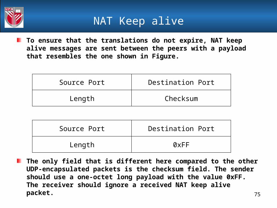
To ensure that the translations do not expire, NAT keep alive messages are sent between the peers with a payload that resembles the one shown in Figure.
The only field that is different here compared to the other UDP-encapsulated packets is the checksum field. The sender should use a one-octet long payload with the value 0xFF. The receiver should ignore a received NAT keep alive packet.
NAT Keep alive
Source Port Destination Port
Length Checksum
Source Port Destination Port
Length 0xFF

76
A topology with a NAT device in front of SPOKE-1-EAST is shown in Figure below. The configuration and debugs for SPOKE-1-EAST doing NAT-T negotiation is shown in “this link”. Peers that run IOS code that support NAT-T automatically exchange this capability. The CLI to control the NAT keep alive timer to disable NAT-T is also indicated in configuration and debugs example.
Example using Cisco Router

77
VPN Implementation

78
Four Office Company Example
Internet
Main Office
Office B Office C
Office D

79
Let us now consider a small company, MDDJ, with four offices, a main office and three remote branch offices.
Communication between these offices is confidential and needs to be protected.
Wisely, MDDJ has decided to employ IPsec to protect this communication but that brings up some deployment options and issues.
Each remote office has a connection to the Internet through which IPsec-protected packets are routed but access to the Internet need not be granted at the remote branch offices.
Each of our deployment scenarios for MDDJ will deal with cases where the remote offices are and are not permitted to have Internet access. When a device has Internet access it must deal with co-existance with a firewall (see next slide).
Four Office Company Example

80
In this scenario of the Four Office Company, each office (remote and main) represents part of the same company.
The trust relationship between all nodes in the VPN is assumed to be extensive (employees have physical access to confidential information) and not suspicious (one node does not trust another any more or less than the rest).
Because of this trust relationship, the firewall and VPN gateway will be in a serial configuration with the firewall connected to the Internet and the VPN gateway connected to the protected network.
This maximizes the security at the cost of minimal firewall configuration without opening up the protected network to an attack that does not already exist (namely a disgruntled employee on the protected network wrecking havoc).
Co-existance with Firewall

81
In a fully-meshed configuration there are peer-wise relationships between each office and the other three offices.
For the small MDDJ network there would be six separate peer-wise connections for the four offices. As the number of peers grows the number of peer-wise connections grows faster.
For instance, if MDDJ had five offices there would be ten peer-wise connections. If there were ten offices there would be forty-five peer-wise connections.
Once we step through the (relatively) simple fully-meshed configuration for MDDJ it should be straightforward to imagine how to implement fully-meshed configurations for much larger networks.
Fully-Meshed Configuration

82
Fully-Meshed Configuration

83
First, let's consider a simple case where access to the global Internet access is permitted only from the main office of MDDJ, and that all peer-wise connections will use the same IPsec and IKE policy suites to protect the traffic and that all traffic between the sites will be protected—no need to restrict it to a specific upper-layer protocol.
Each remote site will be configured in a similar manner: policy to protect traffic from its own protected network to each of the other three protected networks will be via the gateway for that protected network and policy for everything else will be via the gateway at the main office.
Scenario
84
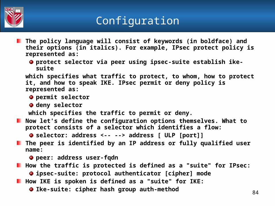
The policy language will consist of keywords (in boldface) and their options (in italics). For example, IPsec protect policy is represented as:
protect selector via peer using ipsec-suite establish ike-suitewhich specifies what traffic to protect, to whom, how to protect it, and how to speak IKE. IPsec permit or deny policy is represented as:
permit selectordeny selector
which specifies the traffic to permit or deny.Now let's define the configuration options themselves. What to protect consists of a selector which identifies a flow:
selector: address <-- --> address [ ULP [port]]The peer is identified by an IP address or fully qualified user name:
peer: address user-fqdnHow the traffic is protected is defined as a "suite" for IPsec:
ipsec-suite: protocol authenticator [cipher] modeHow IKE is spoken is defined as a "suite" for IKE:
Ike-suite: cipher hash group auth-method
Configuration

85
Each component of these constructs can then be further defined as:
Address: W.X.Y.Z or a CIDR-style network specification
User-fqdn: email-style name ([email protected])
Protocol: AH, ESP
ULP (Upper Layer Protocol): TCP UDP
Port: a port number for an upper-layer protocol
Authenticator: HMAC-SHA, HMAC-MD5
Cipher: 3DES, AES, CAST
Mode: tunnel, transport
Hash: SHA, MD5
Group: modp-1024, modp-1536
Auth-method: pre-shared, rsa-sig
Configuration

86
Let's view a couple of examples of how to use this language:
protect 165.248/16 <-- --> 10.1.1/24via 172.24.56.1using ESP HMAC-SHA CAST tunnelestablish AES SHA modp-1536 pre-shared
This describes a policy to protect all traffic between the 165.248/16 network and the 10.1.1/24 network using ESP with HMAC-SHA and CAST in tunnel mode with a peer gateway at gateway 172.24.56.1, and to speak IKE with AES, SHA, pre-shared keys and the Diffie-Hellman group with the 1536 bit prime modulus.
Policy to allow traffic from 165.248.23.8 to 10.1.1.74 and deny everything else would be:
permit 165.248.23.8 <-- --> 10.1.1.74deny 0.0.0.0 <-- --> 0.0.0.0
Configuration

87
Office A will have policy to protect traffic to office B:
protect 10.2/16 <-- --> 10.3/16via 172.24.16.3using ESP HMAC-SHA AES tunnelestablish CAST SHA modp-1536 pre-shared
policy to protect traffic to office C:
protect 10.2/16 <-- --> 10.4/16via 172.24.16.4using ESP HMAC-SHA AES tunnelestablish CAST SHA modp-1536 pre-shared
and policy to protect all other traffic to the main office:
protect 10.2/16 <-- --> 0.0.0.0via 172.24.16.1using ESP HMAC-SHA AES tunnelestablish CAST SHA modp-1536 pre-shared
While it is not strictly necessary some may wish to have an explicit drop rule at the end:
drop 0.0.0.0 <-- --> 0.0.0.0
Configuration

88
The other remote offices will have similar configurations with office B having policy to office A, office C and the main office; and office C having policy to office A, office B and the main office. The main office, though, will be different. It has policy to protect traffic to each of the three remote offices:
protect 0.0.0.0 <-- --> 10.2/16via 172.24.16.2using ESP HMAC-SHA AES tunnelestablish CAST SHA modp-1536 pre-shared
protect 0.0.0.0 <-- --> 10.3/16via 172.24.16.3using ESP HMAC-SHA AES tunnelestablish CAST SHA modp-1536 pre-shared
protect 0.0.0.0 <-- --> 10.4/16via 172.24.16.4using ESP HMAC-SHA AES tunnelestablish CAST SHA modp-1536 pre-shared
Configuration
89
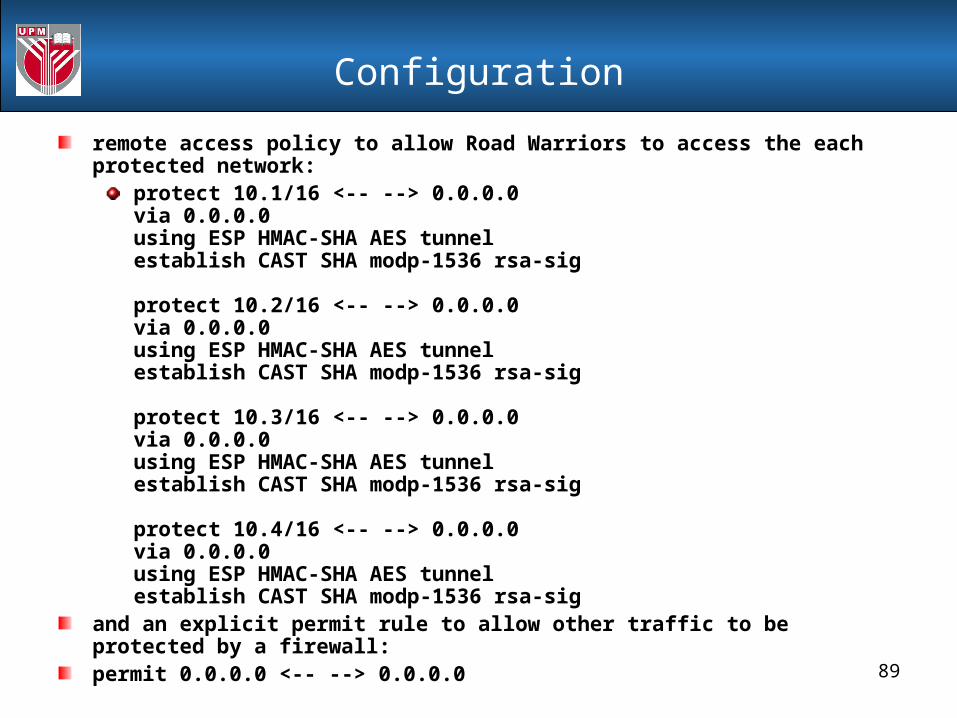
remote access policy to allow Road Warriors to access the each protected network:
protect 10.1/16 <-- --> 0.0.0.0via 0.0.0.0using ESP HMAC-SHA AES tunnelestablish CAST SHA modp-1536 rsa-sig
protect 10.2/16 <-- --> 0.0.0.0via 0.0.0.0using ESP HMAC-SHA AES tunnelestablish CAST SHA modp-1536 rsa-sig
protect 10.3/16 <-- --> 0.0.0.0via 0.0.0.0using ESP HMAC-SHA AES tunnelestablish CAST SHA modp-1536 rsa-sig
protect 10.4/16 <-- --> 0.0.0.0via 0.0.0.0using ESP HMAC-SHA AES tunnelestablish CAST SHA modp-1536 rsa-sig
and an explicit permit rule to allow other traffic to be protected by a firewall:permit 0.0.0.0 <-- --> 0.0.0.0
Configuration

90
Road warriors would need policy to protect traffic to each of the four protected networks via the main office's gateway:
protect 0.0.0.0 <-- --> 10.1/16via 172.24.16.1using ESP HMAC-SHA AES tunnelestablish CAST SHA modp-1536 rsa-sig
protect 0.0.0.0 <-- --> 10.2/16via 172.24.16.1using ESP HMAC-SHA AES tunnelestablish CAST SHA modp-1536 rsa-sig
protect 0.0.0.0 <-- --> 10.3/16via 172.24.16.1using ESP HMAC-SHA AES tunnelestablish CAST SHA modp-1536 rsa-sig
protect 0.0.0.0 <-- --> 10.4/16via 172.24.16.1using ESP HMAC-SHA AES tunnelestablish CAST SHA modp-1536 rsa-sig
Configuration

91
Now let's consider the case where each of the remote branch offices, in addition to the main office, are permitted to have access to the global Internet. This will also allow the remote access policies for each protected network to go directly to that protected network.
There is now no difference between the remote branch office policy and the main office policy. Each gateway defines protection from its protected network to the three other protected networks and defines remote access policy for its protected network.
Scenario 2

92
Office A will have policy to protect traffic to the main office:
protect 10.2/16 <-- --> 10.1/16via 172.24.16.1using ESP HMAC-SHA AES tunnelestablish CAST SHA modp-1536 pre-shared
policy to protect traffic to office B:
protect 10.2/16 <-- --> 10.3/16via 172.24.16.3using ESP HMAC-SHA AES tunnelestablish CAST SHA modp-1536 pre-shared
policy to protect traffic to office C:
protect 10.2/16 <-- --> 10.4/16via 172.24.16.4using ESP HMAC-SHA AES tunnelestablish CAST SHA modp-1536 pre-shared
Configuration

93
policy for remote access users:
protect 10.2/16 <-- --> 0.0.0.0via 0.0.0.0using ESP HMAC-SHA AES tunnelestablish CAST SHA modp-1536 rsa-sig
and an explicit permit rule at the end to allow other traffic to be protected by a firewall:
permit 0.0.0.0 <-- --> 0.0.0.0
Configuration

94
The other remote offices and the main office would all have similar policy protecting traffic from their local protected network to each other's protected network and an explicit permit rule at the end.Since each protected network is permitted to access the Internet directly, Road Warriors would have gateway-specific policy and no longer need to go through the main office to access remote office networks:
protect 0.0.0.0 <-- --> 10.1/16via 172.24.16.1using ESP HMAC-SHA AES tunnelestablish CAST SHA modp-1536 rsa-sig
protect 0.0.0.0 <-- --> 10.2/16via 172.24.16.2using ESP HMAC-SHA AES tunnelestablish CAST SHA modp-1536 rsa-sig
protect 0.0.0.0 <-- --> 10.3/16via 172.24.16.3using ESP HMAC-SHA AES tunnelestablish CAST SHA modp-1536 rsa-sig
protect 0.0.0.0 <-- --> 10.4/16via 172.24.16.4using ESP HMAC-SHA AES tunnelestablish CAST SHA modp-1536 rsa-sig
Configuration

95
Fully meshed deployments are nice because there are no extra hops for a packet to go through to get from one protected network to another.
Each protected network has a peering relationship with each other protected network. On the downside they are complicated to set-up and they don't scale well.
To add a new node to an N-node fully meshed VPN requires N separate policy statements on the new node and one new policy statement on the N other nodes. When N grows large, that's a lot of configuration!
Configuration

96
A way to minimize configuration of large VPNs is to utilize a hub-and-spoke configuration. In this configuration each "spoke" has a peer-wise configuration with the "hub" but not with all other "spokes". This makes growth of the VPN more manageable as the size of the VPN grows because adding a new node to an N-node hub-and-spoke VPN requires a policy statement on the new "spoke" (to connect it to the "hub") and a policy statement on the hub (to connect it to the new "spoke"). The downside is that traffic between "spokes" must be routed through the "hub". That means double the encapsulation and double the cryptographic operations to protect the traffic. Network throughput will, most likely, be affected.
A hub-and-spoke deployment at MDDJ will entail a simple and essentially identical configuration on the three remote branch offices (the "spokes") and a more complicated configuration on the main office (the "hub"), see next slide.
Hub-And-Spoke Configuration

97
Hub-And-Spoke Configuration
Internet
Main Office
Office B Office C
Office D

98
This topology lends itself nicely to the simple configuration—namely, that the only Internet access is via the main office. This way all the remote offices merely specify that all traffic is sent to the main office. For example, office A specifies traffic from its protected network is sent to the main office:
protect 10.2/16 <-- --> 0.0.0.0via 172.24.16.1using ESP HMAC-SHA AES tunnelestablish CAST SHA modp-1536 pre-shared
Each remote office would be similarly configured. Office B would specify traffic from its protected network, 10.3/16, etc.
Configuration

99
The main office would then have policy statements to protect traffic to all the remote office's networks and remote access policies to allow Road Warriors to access those networks via the main office. In fact, the hub-and-spoke configuration on the main office's gateway (and the Road Warrior's remote access policy) is identical to that of the fully-meshed configuration when the only Internet access was via the main office (see above). The difference between the two is with protected traffic between remote offices, in the fully-meshed case it was sent directly, in the hub-and-spoke case it must go through the hub.
Configuration

100
Now, to add a new remote office all that needs to happen is to update the main office gateway's policy to include a statement to the new office. Retaining our convention, let's assume the new network is 10.5/16 and the gateway is 172.24.16.5. The new policy added to the main office gateway would therefore be:
protect 0.0.0.0 <-- --> 10.5/16via 172.24.16.5using ESP HMAC-SHA AES tunnelestablish CAST SHA modp-1536 pre-shared
Configuration

101
and the new office would require the following policy statement:
protect 10.5/16 <-- --> 0.0.0.0via 172.24.16.1using ESP HMAC-SHA AES tunnelestablish CAST SHA modp-1536 pre-shared
In addition, remote access Road Warriors would need to obtain updated policy to obtain access to this new protected network:
protect 0.0.0.0 <-- -->10.5/16via 172.24.16.1using ESP HMAC-SHA AES tunnelestablish CAST SHA modp-1536 rsa-sig
But no configuration of the other remote offices—offices A-C—is needed. When the number of remote offices is large it is easy to see the benefit to using a hub-and-spoke set-up instead of a fully-meshed set-up.
Configuration

102
If we wish to allow each remote office to access the Internet directly but retain our hub-and-spoke configuration for ease of growth each remote office would need policy for each protected network, including the new one, via the main office gateway and an explicit permit policy statement to pass non-VPN traffic to a firewall. It should not be hard to see what is happening. We have just lost the benefit of the hub-and-spoke configuration—addition of a new office now requires all other offices to be reconfigured!
Configuration

103
Deploying IPSec on a network requires care. One must always keep in mind the threat that IPSec is being deployed to counter against. That can influence how VPN gateways and firewalls interact and can also dictate what sort of access is allowed. When supporting remote access it is important to keep in mind that policies are no longer symmetric, and that quite often a certification authority will be needed to bind user's identities to public keys.
Some of the configurations for the various deployment scenarios we discussed are very similar, even though the network to be protected and the threats to be protected against were all quite different. It is important, though, to keep in mind that when planning and designing a secure network one must look at the needs and the threat to develop the model and produce the configuration, not the other way around. It is possible (and less work) to take an existing configuration and shoehorn in the network design, but that would most likely result in unforeseen scaling problems at best and security flaws at worst.
Summary

104
How Do You Want Protect Your Network System
Thank YouSee You Next Week