1 jupiter tfm simulation environment. 2 topics left to impress you with 09001640 number of topics...
TRANSCRIPT
1
Jupiter TFM Simulation Environment

2
Topics Left to Impress You With
0900 1640
Number of Topics Left
0
100

3
What is Jupiter TFM Simulation Environment (JSE)?
• JSE is a proven, distributed, human-in-the-loop simulation environment that consists of two parts:
– A core flight simulator (potential to simulate the entire NAS for a day or multiple days)
– An emulator of the traffic flow management infrastructure
• Objectives of using JSE
– Evaluation and development of new concepts in congestion management
• Procedural change evaluation and validation
• Technology integration and evaluation without effecting the operational environment
– Engage key stakeholders through interactive war games
– Fast-time simulations for post analysis and reporting

4
JSE/ISE Operating Environment
Jupiter Simulation Environment
TFMS(Hub Site Emulation)
Host(Flight
Simulation)
Flight Data
ADL
Flight Messaging
CDM Messaging
Flight Messaging
Host(Flight
Simulation)
Host(Flight
Simulation)
Host(Flight
Simulation)
Flight DataFlight Data
ADL
TMI/EDCT
Airlines Operation Center
Generic Substitution
ToolCDM
messaging
FSMCapacity/Demand
Balancing
RMTRoute Options
Generation, Early Intent
Research Organizations
Mitre’s CRCTCollaborative
Routing Coordination Tool
NASA’s FACETATM Concept
Evaluation Tool
ATCSCC
FSAPost
operational delay
analysis
RMTRoute Options
Generation, Early Intent
TFMS Remote Site
FSMCapacity/Demand
Balancing
Flight Messaging
CDM Messaging
5
JSE’s Flight Simulation
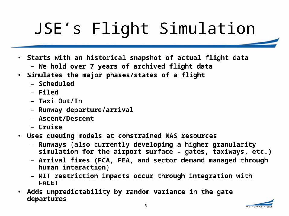
• Starts with an historical snapshot of actual flight data– We hold over 7 years of archived flight data
• Simulates the major phases/states of a flight– Scheduled– Filed– Taxi Out/In– Runway departure/arrival– Ascent/Descent– Cruise
• Uses queuing models at constrained NAS resources– Runways (also currently developing a higher granularity simulation for the
airport surface – gates, taxiways, etc.)– Arrival fixes (FCA, FEA, and sector demand managed through human
interaction)– MIT restriction impacts occur through integration with FACET
• Adds unpredictability by random variance in the gate departures

6
JSE’s TFM Infrastructure Emulation
• Allows various users of the system to interact while the simulation is running
– Allows traffic managers, airline dispatchers, and researchers the ability to interact with the simulation
– Network connections exist for remote users to participate in HITLs
• Many of the standard TFM and CDM tools can connect to the simulation environment as they would to the operational environment
– Flight Schedule Monitor
– Enhanced Substitution Module
– Route Management Tool
– Real-time Flight Schedule Analyzer
– Departure Flow Management

7
JSE’s TFM Infrastructure Emulation (Cont’d)
• Runs many of the same algorithms that exist in TFMS today
– Contains Adaptive Compression logic
– CDM Messaging
– Substitution processing
– Pop-up flight EDCT assignments
• Uses an internal trajectory modeler to predict demand at points in the airspace, such as Centers, Sectors, and user-defined Flow Constrained/Evaluation Areas
• Compatible with TFM Modernization
– SEVEN
– Enhanced pop-up processing

8
System Architecture
Sim
ula
tio
n S
yste
m“H
os
t”
Web Container EJB Container
ETMS System Logic
Web Services
DataRequest
DataModification
Data Layer
J2E
E A
pp
lica
tio
n S
erv
er
“ET
MS
”
Flights
Airports
Airspace
Fixes/Navaids
CDM Messaging
Delay Processing
Flight Plan Processing
Demand Predictions
External Application
JSE Feed(XML)
JSE Abstraction Layer (API)
Flights
Airports
Airspace
Fixes/Navaids
Agent
ComWeb
TrajectoryPredictor Fix
AirportFlight
Agent
ComWeb
TrajectoryPredictor Fix
AirportFlight
Simulation Manager
Com
Web
Agent
Time Manager
Data Initializer
Event Manager
ScenarioArchive
Scenario Manager
Simulation History

9
JSE Tools and Technologies
RMT-R
FSM

10
User Interaction with JSE
• Traffic Management Initiatives
– GDP, GS, AFP
– Broadcasts out EDCTs
• Flow Constrained/Evaluation Areas
– Provides back-predicted entry times into airspace using its internal trajectory model
• Initial Flight Plans and Amended Flight Plans
– Introduce new flights using a flight plan
– Simulates flights on their revised trajectories
• CDM Messaging
– Updated gate times
– Substitutions (simplified and slot credit)
– Flight cancellations and new flight creation

11
Successful Uses of JSE (2002-2008)
• Slot Credit Substitutions
– From concept to operational deployment in 14 months
• Vision 100 Collaborative Planning exercises
• General Aviation Airport Programs (GAAP)
• Airspace Flow Programs
– Tremendous involvement from industry stakeholders (Bi-weekly HitLs during concept development)
– Heavy emphasis on procedural development
• TFM Training
– Multiple scenarios
• Departure Flow Management
– User group HitLs
• SEVEN
– Ongoing user group HitLs leading to an operational deployment in 2010/2011

12
SEVEN – System Enhancements for Versatile Electronic Negotiation
Interactive Dynamic Flight ListUser Submitted Prioritized List with Multiple Options
13
Basic Idea
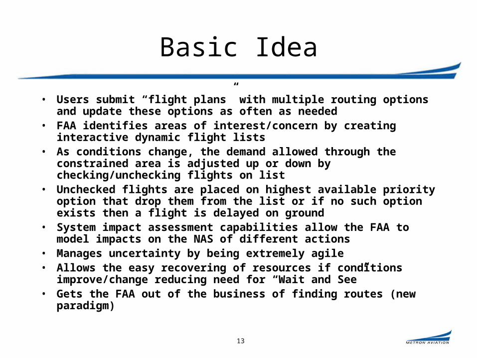
• Users submit “flight plans” with multiple routing options and update these options as often as needed
• FAA identifies areas of interest/concern by creating interactive dynamic flight lists
• As conditions change, the demand allowed through the constrained area is adjusted up or down by checking/unchecking flights on list
• Unchecked flights are placed on highest available priority option that drop them from the list or if no such option exists then a flight is delayed on ground
• System impact assessment capabilities allow the FAA to model impacts on the NAS of different actions
• Manages uncertainty by being extremely agile• Allows the easy recovering of resources if conditions improve/change
reducing need for “Wait and See”• Gets the FAA out of the business of finding routes (new paradigm)
14
Multiple Routing Options
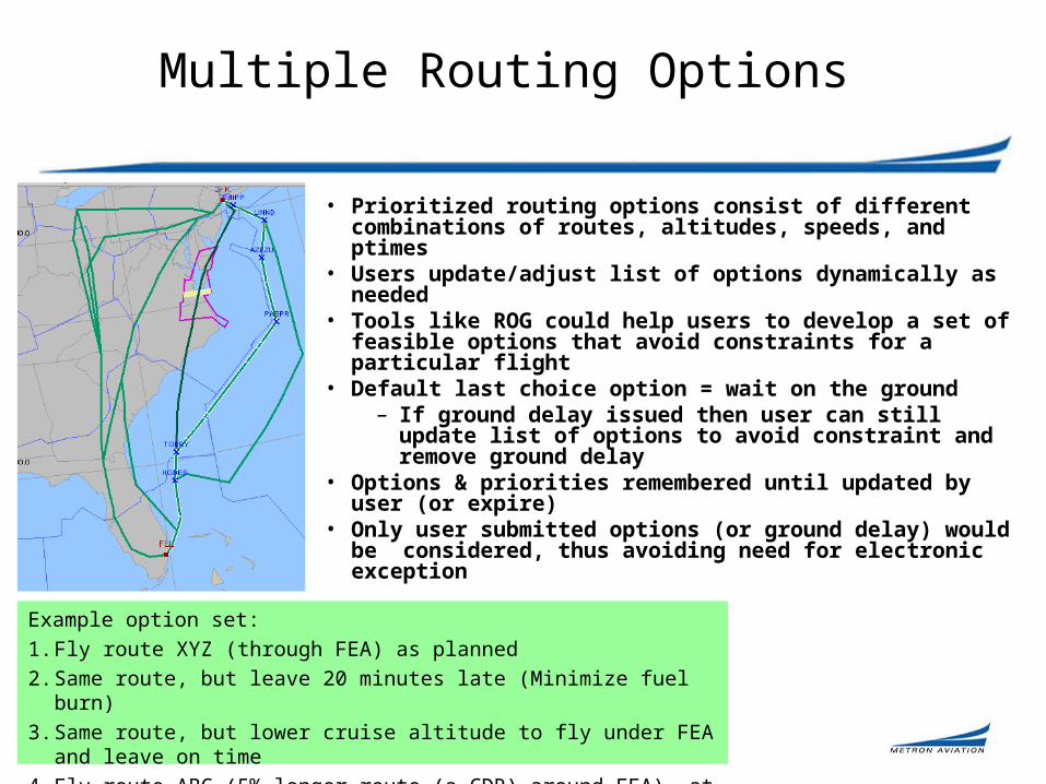
• Prioritized routing options consist of different combinations of routes, altitudes, speeds, and ptimes
• Users update/adjust list of options dynamically as needed• Tools like ROG could help users to develop a set of
feasible options that avoid constraints for a particular flight
• Default last choice option = wait on the ground– If ground delay issued then user can still update list
of options to avoid constraint and remove ground delay
• Options & priorities remembered until updated by user (or expire)
• Only user submitted options (or ground delay) would be considered, thus avoiding need for electronic exception
Example option set:
1. Fly route XYZ (through FEA) as planned
2. Same route, but leave 20 minutes late (Minimize fuel burn)
3. Same route, but lower cruise altitude to fly under FEA and leave on time
4. Fly route ABC (5% longer route (a CDR) around FEA), at altitude H (optimum?), at slightly slower speed (fuel efficient), and leave on time

15
Interactive Dynamic Flight Lists
• Lists can be created for any NAS resource of “interest”
• Lists are dynamic: update as changes occur• Lists are interactive: demand is managed from within
the list• Flights that are checked can use the resource • Unchecked flights are placed on highest priority
option that avoids the resource. If no such option exists, then a flight is delayed on ground (if not yet active)
• “Auto-suggest” algorithms could automate which flights are removed/added to list based on rationing/equity concerns (dial-up/dial down concept)
• Lists allow for the re-capture of capacity when conditions unexpectedly improve/change (dial-up concept)

16
Collaborative Routing Resource Allocation Tool (CRRAT)
Functionality
FACET interaction
and HITL usage

17
CRRAT Overview
CRRAT allows NAS users to input multiple routing options with associated switching criteria to FAA resource allocation processes (right). Demand for airspace is brought down below capacity levels (below) by the CRRAT rationing algorithm.

18
What is CRRAT?
• An algorithm to assign scarce (constrained) NAS resources to flights and/or carriers, given capacities on those constraints and requests to use them
• Both equity and efficiency of solution are considered• Fast run time to this NP-hard scheduling problem
– Solving NAS-wide problems (several hundred resources and thousands of flights) in seconds to minutes.
• Highly flexible and configurable– ‘Resources’ could be airports, runways, taxi spots, waypoints,
sectors, etc. It doesn’t know/care what the resources are
• Collaborative: designed to dovetail with user needs and input – Multiple route options per flight

19
Multi-Objective Purpose
• Allocate scarce NAS resources• Maximize (i) system efficiency, (ii) airline
efficiency, and (iii) equitysubject to constraints that
– Each flight be assigned a viable path and departure time
– For each time period, and for each resource, the capacity is not violated

20
Sample Applications
• NAS-wide flow control– E.g. All sectors and airports
• Flow Constrained Area (FCA) – Sectors not recommended
• GDP airports (trivial application)• Large-scale weather fronts
– e.g. that restrict flow to the east coast of the United States, storm systems that block passage across Cleveland Center, and the TFM desire to reduce arrival flow to the New York City area.
• Multi-fix GDP problem– Each fix is established as a resource, as well as the airport itself.– Each flight intending to arrive at the GDP airport requires use of
exactly one of the arrival fix resources and the airport resource.
21
Configurable Priority Rules
Examples of flight prioritization rules that can be achieved
• Grover-Jack (First-come First-served)
• Ration-by-Schedule (RBS)/(First-scheduled First-served)
• Accrued Delay
• Time-ordered Accrued Delay (TOAD)
• Random Flight Selection
• And many more…
• Best algorithms achieving 15-30% less total delay than RBS
By rearranging the order of the priority modules,
variations on the algorithm can be created by the user. (Mr. Potato Head, if you will)

22
CRRAT Software Summary
CRRAT allocates multiple, capacitated resources…
…to flights with alternate route preferences…
…using customizable rationing schemes.

23
Input / Output
Demand forecast:
Proposed routes and depart times for
flights.
Capacity forecast:
Max arrival rate for airports and airspace sectors in each future t.
CRRAT Dispatching Rule:
Process flights one at a time (resource hopping).
Apply flight prioritization rules
Set control actions on each flight.
Controls:
• Controlled departure time
• Controlled route
Input Algorithm Output
Metrics:
Equity
Total delay
Etc.
Repeat

24
CRRAT Library
• Generic Java library with the core resource allocation capabilities from CRRAT– Multi-resource, interdependent scheduling
– Multiple routes per flight
• Stable, reusable software, currently used by – SEVEN
– Command and Control SBIR
– CRRAT

25
FACET Interaction
• CRRAT exists as an application with NASA’s Future ATM Concepts Evaluation Tool (FACET)
Flights
NAS Element Definitions
Projected Flight Demand for Constraints
FACET CRRAT

26
CRRAT HITLs
• CRRAT played a large role in the launching of the Airspace Flow Program (AFP) Traffic Management Initiatives– AFP supporting analysis in 2004-2005
• Demonstrated the failings of GDPs in support of SWAP and proffered AFPs as an alternative
– CRRAT served as a prototype AFP system, integrated with JSE
• Demonstrations to senior FAA decision makers in early 2005
– AFPs went operational in 2006

27
CRRAT HITLs
Period of constraint
FEA over and around weather
GDP airports

28
CRRAT HITLs
Effect of 10 GDPs
Most delay assigned to flights not in FCA
Most flights in FCA not controlled at all

29
Backup Slides

30
Brief History
• Phase 1 and Phase 2 SBIR project sponsored by NASA (2002-2004)– Major features and methodology developed
• Elaboration of Jason Burke MS thesis (UMD)• Further embellishment through C2 SBIR and
various FAA projects • Used in support of initial AFP analysis and
demonstrations (2005)

31
More Detailed Input / Output

32
Core Algorithm
Award resources to f1 in accordance with stated route preference and capacity availability
Until no more flights
Update status (available capacity) of affected resources.
Order the current list of flights by nested priority rules: f1, f2,…,fn
Using combination of priority algorithms. Equity and efficiency can be taken into account here. Simple algorithms (e.g. RBS) make one pass thru flight list
– very quick!
Capacity constraints taken into account here User preferences: carrier-specified tradeoff between
ground and air delay for route selection.
Incremental progress toward a feasible solution

33
Output (Decision Variables)
• Each flight f F receives a path (sequence of resources) that it will use along with the time it should be at each resource

34
The objective is to create an algorithm that allocates
en route resources in a strategic, CDM-compatible
manner
35
Alternate Approaches We Considered
• Bertsimas-Stock (MIT)
• Goodhart & Yano (UCB)
• Ray Staats (AFIT)
• NEXTOR-UMD: ERAP
• CDM-FCA Working Subgroup
• Mitre-CAASD: CRCT offspring
• MetronAV/NASA: CRRAT
• EUROCONTROL) Computer Aided Route Allocation Tool (CARAT) is an optimization rerouting tool
Academic (optimization models) Industry software and tools
• Our work captures the desirable properties of a rationing algorithm

36
Incorporating Routing Preferences
• Three routes available to a flight. Air delay (e.g. extra miles flown over the shortest middle route) can be computed in advance.
• Once potential ground delays are known for each route, then cost of each route for the carrier can be computed.
Orig. Dest.
Cost =(ground + 2 air)
Additional AirMinutes
Ground DelayMinutes
FCA
10
0
20
30
60
40
10
60
0
Orig. Dest.
Cost =(ground + 2 air)
Cost =(ground + 2 air)
Additional AirMinutes
Additional AirMinutes
Ground DelayMinutes
Ground DelayMinutes
FCA
10
0
20
30
60
40
30
60
40
10
60
0
10
60
0
• All computations but the ground delays can be computed and supplied to an automation in advance.
• This way, an FAA algorithm can choose the most appropriate route for each flight, taking carrier preferences into account.
Upper route is cheapest