1 k. salah ethernet technology electromagnetic spectrum guided transmission media –twisted pair...
Post on 22-Dec-2015
217 views
TRANSCRIPT

K. Salah 1
Ethernet Technology
• Electromagnetic Spectrum
• Guided Transmission Media
– Twisted Pair
– Coaxial cable
– Optical fiber
• Unguided Transmission Media
– Terrestrial Microwave
– Satellite
– Radio
– IR
– Cellular Telephony

K. Salah 2
Electromagnetic Spectrum

K. Salah 3
Guided Transmission Media
• Twisted Pair
• Coaxial cable
• Optical fiber

K. Salah 4
Twisted Pair
• Most common medium
• Telephone network– Between house and local exchange (subscriber loop)
• Within buildings– To private branch exchange (PBX)
• For local area networks (LAN)– 10Mbps or 100Mbps
• Pros and Cons:– Cheap– Easy to work with– Low data rate– Short range, about 100 meters.

K. Salah 5
Unshielded and Shielded TP
• Unshielded Twisted Pair (UTP)– Ordinary telephone wire– Cheapest– Easiest to install– Suffers from external EM interference
• Shielded Twisted Pair (STP)– Metal braid or sheathing that reduces
interference– More expensive– Harder to handle (thick, heavy)– Capacity 10-155 Mbps
UTP Categories
• Cat 3– up to 16MHz– Voice grade found in most
offices
• Cat 4– up to 20 MHz
• Cat 5– up to 100MHz– Commonly pre-installed in
new office buildings
RJ-11 vs. RJ-45
• RJ-11 is a typical UTP phone connector. Has 2 pairs.
• RJ-45 is a UTP connector. Has 4 pairs.

K. Salah 6
Coaxial Cable
• Most versatile medium
• Television distribution
– Ariel to TV
– Cable TV
• Long distance telephone transmission
– Can carry 10,000 voice calls simultaneously
– Being replaced by fiber optic
• Short distance computer systems links
• Local area networks
Transmission Characteristics Analog
Amplifiers every few km Closer if higher
frequency Up to 500MHz
Digital Repeater every 1km Closer for higher data
rates
K. Salah 7
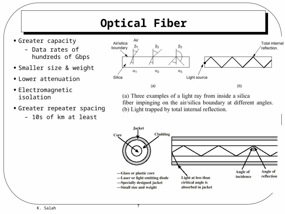
Optical Fiber
• Greater capacity
– Data rates of hundreds of Gbps
• Smaller size & weight
• Lower attenuation
• Electromagnetic isolation
• Greater repeater spacing
– 10s of km at least
K. Salah 8
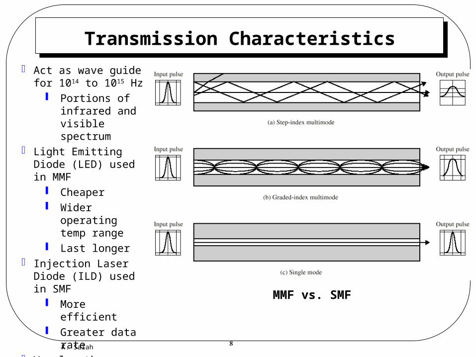
Transmission Characteristics
Act as wave guide for 1014 to 1015 Hz
Portions of infrared and visible spectrum
Light Emitting Diode (LED) used in MMF
Cheaper Wider
operating temp range
Last longer Injection Laser Diode
(ILD) used in SMF More efficient Greater data
rate Wavelength Division
Multiplexing (WDM) using light prisms.
MMF vs. SMF
K. Salah 9
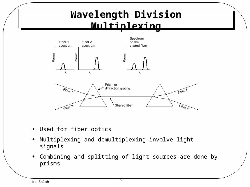
Wavelength Division Multiplexing
• Used for fiber optics
• Multiplexing and demultiplexing involve light signals
• Combining and splitting of light sources are done by prisms.
K. Salah 10
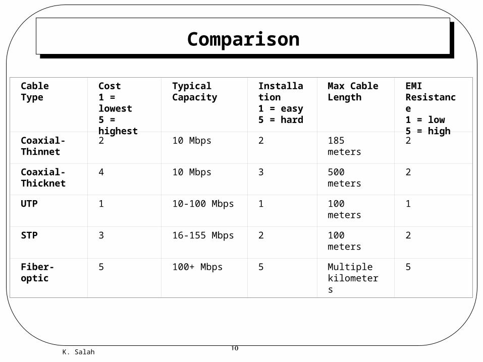
Comparison
Cable Type Cost1 = lowest5 = highest
Typical Capacity
Installation1 = easy5 = hard
Max Cable Length
EMI Resistance1 = low5 = high
Coaxial-Thinnet
2 10 Mbps 2 185 meters 2
Coaxial-Thicknet
4 10 Mbps 3 500 meters 2
UTP 1 10-100 Mbps 1 100 meters 1
STP 3 16-155 Mbps 2 100 meters 2
Fiber-optic 5 100+ Mbps 5 Multiple kilometers
5

K. Salah 11
Data Link Layer
• The Logical Link Control (LLC) sublayer
– Framing
– Flow Control
– Error Control
• The Media Access Control (MAC) sublayer
– Random Access (CSMA)
– Token Passing

K. Salah 12
LLC Framing
• Framing is partitioning a bit stream into discrete units or blocks of data.
• To distinguish between same bit pattern of real user data and the start-stop, bit stuffing is employed.
– E.g., stuff a bit after every 5th consecutive ones.

K. Salah 13
Ethernet/802.3 Frame
• Preamble is for synchronization
• Source and destination are 48 bits each and have the MAC address, e.g, 08:00:20:01:D6:2A. The left 3 bytes are vendor specific, and the others are serial number of device assigned by Sun. 00:00:0C is CISCO.
• This MAC address is different than the IP address !!!

K. Salah 14
CSMA/CD
• Step 1. “Listen before talking”.
• Step 2. If channel is quiet for a certain time, called interframe gap (IFG), then transmit. “Talk if quiet”.
• Step 3. If channel is busy, monitor the channel until it is quiet for IFG period before transmitting. “Wait for quiet before talking.”
• Step 4. Monitor the channel continuously during transmission to detect collisions. “Listen while talking”.
• Step 5. If collision occurs, the first node recognizes it will send a jam signal to ensure that all other stations detect the collision. Transmitters should stop immediately, receivers should reject data, and others wishing to transmit should recalculate their backoff period. “A buzzer sounds off indicating we have more than one talker at a time.”
• Step 6. All nodes wish to transmit must now wait a random period called “backoff” and attempt again to spread out collisions. “Backoff” is based on BEB algorithm (Binary Exponential Backoff). After 16 collisions, drop the frame to be transmitted.
K. Salah 15
Notes
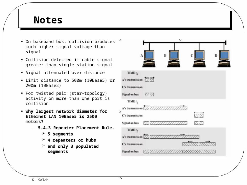
• On baseband bus, collision produces much higher signal voltage than signal
• Collision detected if cable signal greater than single station signal
• Signal attenuated over distance
• Limit distance to 500m (10Base5) or 200m (10Base2)
• For twisted pair (star-topology) activity on more than one port is collision
• Why largest network diameter for Ethernet LAN 10Base5 is 2500 meters?
– 5-4-3 Repeater Placement Rule. 5 segments 4 repeaters or hubs and only 3 populated
segments

K. Salah 16
Repeaters, Bridges, & Switches
• Repeater
• Hub
• NIC
• Bridges
• Switches
• VLANs
• GbE

K. Salah 17
Hardware Components• Repeater
– Layer 1 device that provides physical and electrical connections.
– It receives signals from one cable segment, regenerates, retimes, and amplifies them, and then transmits these “revitalized” signals to another cable segment.
– Transmits in both directions– Joins two segments of cable– No buffering– No logical isolation of segments
• Hub– Used to describe a repeater– Can be “repeater hub”, “switching hub”, bridging hub”.
• NIC– Network Interface Card– Performs layer-2 functions: framing, error detection, and
flow control.– Performs layer-1 functions by converting the bits into
electrical signals using appropriate coding scheme.
K. Salah 18
Bridges
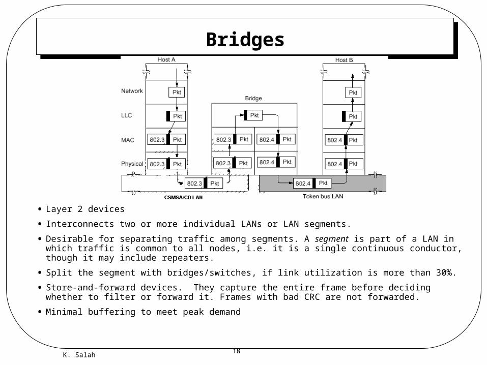
• Layer 2 devices
• Interconnects two or more individual LANs or LAN segments.
• Desirable for separating traffic among segments. A segment is part of a LAN in which traffic is common to all nodes, i.e. it is a single continuous conductor, though it may include repeaters.
• Split the segment with bridges/switches, if link utilization is more than 30%.
• Store-and-forward devices. They capture the entire frame before deciding whether to filter or forward it. Frames with bad CRC are not forwarded.
• Minimal buffering to meet peak demand
K. Salah 19
Bridges Standards• Transparent Bridges
– Operate in promiscuous mode. – Bridging is transparent to stations, as if they are on one single LAN.– “plug and play” unit, learns addresses connecting to ports by examining source and
destination addresses.– examines the destination address to forward or filter frames.– All broadcast and multicast frames are forwarded.
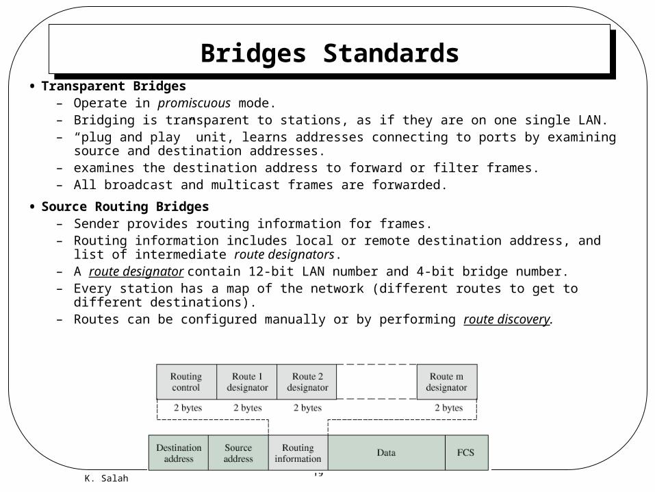
• Source Routing Bridges– Sender provides routing information for frames. – Routing information includes local or remote destination address, and list of intermediate
route designators.– A route designator contain 12-bit LAN number and 4-bit bridge number.– Every station has a map of the network (different routes to get to different destinations).– Routes can be configured manually or by performing route discovery.

K. Salah 20
Bridges Standards (cont.)
• Network loops can happen. Can cause broadcast storms that can bring the LAN down.
• Spanning Tree algorithm resolves network loops.
• Algorithm is based on graph theory. – Any connected graph, consisting of nodes
and edges connecting pairs of nodes, there is a spanning tree of edges that maintains the connectivity of the graph but contains no closed loops.
– Each LAN is a node and each bridge is an edge.
– Specified in IEEE 802.1. It involves a brief exchange of messages among all bridges to discover the minimum-cost spanning tree. Whenever there is a change in topology, the bridges automatically recalculate the spanning tree.
• Disabling B3-LAN4 port will result in a spanning tree. If B4 fails, the algorithm should enable this port again.
Spanning Tree

K. Salah 21
Switches
• Switches can operate at different layers: layer 2, 3, 4, and 7..
• Basically a switch is hardware based, not software based.
• Three types of layer 2 switches:
– Store-and-Forward Switch Similar to store-and-forward bridge. Store entire frame, check for errors,
and then switch to the other ports, based on the destination MAC address.
– Cut-Through Switch The transmission of frame begins as soon as it reads the destination
MAC address. Two switch fabric/matrix designs: Crossbar Backplane with bus speed > aggregate port speeds
– Hybrid Switch Reliability: store-and-forward. Turn ON when errors are high. Low latency: cut-through. Turn ON when errors are low.

K. Salah 22
VLANs
• VLAN is a logical grouping of nodes using Ethernet switches. Nodes don’t need to be connected physically to the same switch. A broadcast frame will be heard by all nodes within VLAN.
• Benefits:– Isolates broadcasts– Frees up network from physical
locations– Easily shares resources. A server
can be part of multiple VLANs.– Performance. Easily can be
enhanced by creating new VLANs.– Security. By containing who can
listen to broadcast.
• VLAN Membership (implicit tagging)– Port-based– MAC-based– Layer 3/IP– Combination of the above

K. Salah 23
Gigabit Ethernet
• With GbE CSMA/CD
– Network diameter shrinks to 25 meter. This is not a good option.
– Therefore, minimum frame time was increased to 512 bytes. This gives network diameter of 200 meter, but waste in bandwidth especially for small size data.
• Most common use is point-to-point fame switching.
– No CSMA/CD
• We have now 10GbE that can go more than 50 km over SMF.