1. package contents 3. media converter chassis front mc ...figure 5-1 mc-700 rear panel the rear...
TRANSCRIPT
- 1 -
- 2 -
- 3 -
- 4 -
- 5 -
- 6 -
- 7 -
- 8 -
1. Package Contents
Before start installing the Converter, verify the package contains the following parts:
● TheMediaConverterChassisx1
● User'sManualx1
● MountingAccessory(for10/19”ChassisShelf)x1
● RubberFeetx4
● ACPowerCordx1
Ifanyofthesearemissingordamaged,pleasecontactyourdealer immediately, if possible, retain the carton includingthe original packing material, and use them against torepacktheproductincasethereisaneedtoreturnittousfor repair.
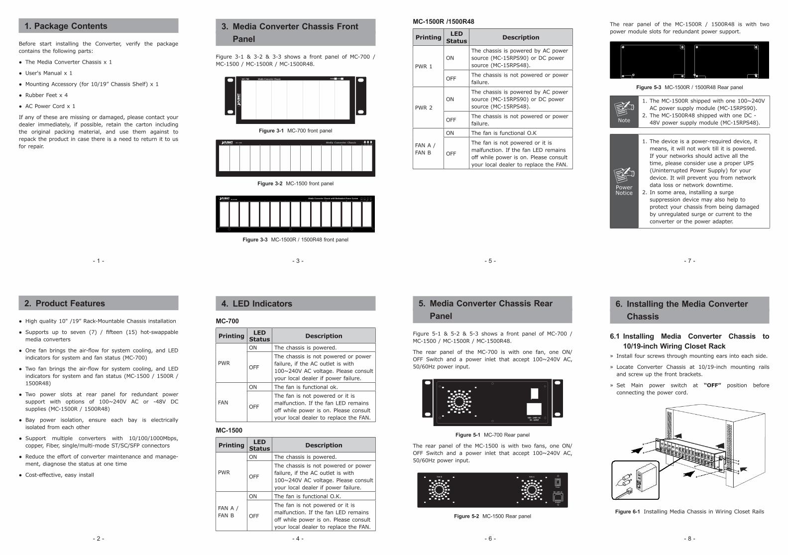
3. Media Converter Chassis Front Panel
Figure 3-1 & 3-2 & 3-3 shows a front panel of MC-700 /MC-1500/MC-1500R/MC-1500R48.
Figure 3-1 MC-700 front panel
Figure 3-2 MC-1500 front panel
Figure 3-3 MC-1500R / 1500R48 front panel
The rear panel of the MC-1500R / 1500R48 is with twopowermoduleslotsforredundantpowersupport.
Figure 5-3 MC-1500R / 1500R48 Rear panel
Note
1.TheMC-1500Rshippedwithone100~240VACpowersupplymodule(MC-15RPS90).
2.TheMC-1500R48shippedwithoneDC-48Vpowersupplymodule(MC-15RPS48).
PowerNotice
1.Thedeviceisapower-requireddevice,itmeans,itwillnotworktillitispowered.Ifyournetworksshouldactiveallthetime,pleaseconsideruseaproperUPS(UninterruptedPowerSupply)foryourdevice.Itwillpreventyoufromnetworkdatalossornetworkdowntime.
2.Insomearea,installingasurgesuppressiondevicemayalsohelptoprotectyourchassisfrombeingdamagedbyunregulatedsurgeorcurrenttotheconverterorthepoweradapter.
MC-1500R /1500R48
PrintingLED
StatusDescription
PWR1
ONThechassisispoweredbyACpowersource(MC-15RPS90)orDCpowersource(MC-15RPS48).
OFFThechassisisnotpoweredorpowerfailure.
PWR2
ONThechassisispoweredbyACpowersource(MC-15RPS90)orDCpowersource(MC-15RPS48).
OFFThechassisisnotpoweredorpowerfailure.
FANA/FANB
ON ThefanisfunctionalO.K
OFF
Thefanisnotpoweredoritismalfunction.IfthefanLEDremainsoffwhilepowerison.PleaseconsultyourlocaldealertoreplacetheFAN.
2. Product Features
● Highquality10"/19”Rack-MountableChassisinstallation
● Supports up to seven (7) / fifteen (15) hot-swappablemediaconverters
● One fan brings the air-flow for system cooling, and LEDindicatorsforsystemandfanstatus(MC-700)
● Two fan brings the air-flow for system cooling, and LEDindicatorsforsystemandfanstatus(MC-1500/1500R/1500R48)
● Two power slots at rear panel for redundant powersupport with options of 100~240V AC or -48V DCsupplies(MC-1500R/1500R48)
● Bay power isolation, ensure each bay is electricallyisolatedfromeachother
● Support multiple converters with 10/100/1000Mbps,copper,Fiber,single/multi-modeST/SC/SFPconnectors
● Reducetheeffortofconvertermaintenanceandmanage-ment,diagnosethestatusatonetime
● Cost-effective,easyinstall
4. LED Indicators
MC-700
Printing LED Status Description
PWR
ON Thechassisispowered.
OFF
Thechassisisnotpoweredorpowerfailure,iftheACoutletiswith100~240VACvoltage.Pleaseconsultyourlocaldealerifpowerfailure.
FAN
ON Thefanisfunctionalok.
OFF
Thefanisnotpoweredoritismalfunction.IfthefanLEDremainsoffwhilepowerison.PleaseconsultyourlocaldealertoreplacetheFAN.
MC-1500
Printing LED Status Description
PWR
ON Thechassisispowered.
OFF
Thechassisisnotpoweredorpowerfailure,iftheACoutletiswith100~240VACvoltage.Pleaseconsultyourlocaldealerifpowerfailure.
FANA/FANB
ON ThefanisfunctionalO.K.
OFF
Thefanisnotpoweredoritismalfunction.IfthefanLEDremainsoffwhilepowerison.PleaseconsultyourlocaldealertoreplacetheFAN.
5. Media Converter Chassis Rear Panel
Figure 5-1 & 5-2 & 5-3 shows a front panel of MC-700 /MC-1500/MC-1500R/MC-1500R48.
The rear panel of the MC-700 is with one fan, one ON/OFF Switch and a power inlet that accept 100~240V AC,50/60Hzpowerinput.
Figure 5-1 MC-700 Rear panel
The rear panel of the MC-1500 is with two fans, one ON/OFF Switch and a power inlet that accept 100~240V AC,50/60Hzpowerinput.
Figure 5-2 MC-1500 Rear panel
6. Installing the Media Converter Chassis
6.1 Installing Media Converter Chassis to 10/19-inch Wiring Closet Rack
» Installfourscrewsthroughmountingearsintoeachside.
» Locate Converter Chassis at 10/19-inch mounting railsandscrewupthefrontbrackets.
» Set Main power switch at “OFF” position beforeconnectingthepowercord.
Figure 6-1 InstallingMediaChassisinWiringClosetRails

- 9 -
- 10 -
- 11 -
- 12 - - 13 - - 14 -
6.2 Installing Converters to the Media Converter Chassis
» TurnofftheConverterChassispower.
» Verify the Media Converter is right for this Chassis andlocate +5VDC power jack on converter back, carefullyslide in and plug to match 10”/19” Chassis slot +5VDC receptacle. Push up the picket fence to lock theconverters.
Note
The slide-in Media Converters and ConverterChassis shouldbe suppliedonly fromPLANET,both Media Converters and Chassis are builttomatcheachotheratdimensions,DCpowerjack,andDCreceptacleandpowersafety.
» Ensurethatthereisnoactivityinthenetwork.
» Connectthemediacablefornetworkconnection.
» Turnonthechassispower,thePowerLED,andbothFANLEDindicatorswilllightup.
7. Product Specifications
MC-700 Converter Chassis Specifications
Dimension217mmx88.5mmx140mm(WxHxD),2Uheight
Converter Slots 7slots
Power Input 100~240VAC,50/60Hz
Power Consumption
40Wattsmaximum/136BTU
Power Output Per Slot
+5VDC
DC Plug Per Slot 2.5mmDCreceptacle
LED Indication 2;Power,FAN
FAN 1
Temperature / Humidity
Operating Environment 0~50DegreeC;Humidity:5~90%non-condensingStorage Environment-40~70DegreeC;Humidity:5~90%non-condensing
Emission FCCPart15ClassA,CE
6.3 Converter Check Point
Fiber Port
Attachthefibercable.TheTx,Rxfibercablemustbepairedatbothends.
2.5mmDCReceptacle2.5mm+5Vforeachslot
TP Port
Attach UTP Cat. 3 or 5 ca-ble to TP port.
DCreceptacleis2.5mmwidethatconformstoandmatchestheMediaConverter2.5mmDCjack'scentralpole.Donotinstallanyimproperunit,modeloftheMediaConverter.
Note
For safety reason, it is recommended storingthe AC adapter of the converter in a knownsecuredplace.Formoreaboutconverter,refertotheuserguideoftheconverter.
MC-1500 Converter Chassis Specifications
Dimension440mmx103mmx180mm(WxHxD),2.4Uheight
Converter Slots 15slots
Power Input 100~240VAC,50/60Hz
Power Consumption
70Wattsmaximum/238BTU
Power Output Per Slot
+5VDC
DC Plug Per Slot 2.5mmDCreceptacle
LED Indication 3;Power1,FANA,FANB
FAN 2
Temperature / Humidity
Operating Environment 0~50DegreeC;Humidity:5~90%non-condensingStorage Environment-40~70DegreeC;Humidity:5~90%non-condensing
Emission FCCPart15ClassA,CE
MC-1500R / MC-1500R48 Converter Chassis Specifications
Model MC-1500R MC-1500R48
Dimension440mmx103mmx180mm(WxHxD),2.4Uheight
Converter Slots 15slots
Power Input100~240VAC,1.5A,50-60Hz
DC-48V,2A,Range:-30V~-60V
Power Consumption
8.4Watts/28BTU(1xpowersupply,notincludeconverters)80Watts/272BTU(Fullloading)
5.3Watts/18BTU(1xpowersupply,notincludeconverters)80Watts/272BTU(Fullloading)
Power Output Per Slot
+5VDC
DC Plug Per Slot
2.5mmDCreceptacle
LED Indication 4;Power1,Power2,FANA,FANB
FAN 2
Temperature / Humidity
Operating Environment 0~50DegreeC;Humidity:5~90%non-condensingStorage Environment-40~70DegreeC;Humidity:5~90%non-condensing
Emission FCCPart15ClassA,CE
8. Customer Support
Thank you for purchase PLANET products. You can browseour online FAQ resource at the PLANET Web site first tocheck if it couldsolveyou issue. Ifyouneedmoresupportinformation,pleasecontactPLANETMediaConvertersupportteam.
PLANETonlineFAQ:
http://www.planet.com.tw/en/support/faq.php?type=3
MediaConvertersupportteammailaddress:
Copyright©PLANETTechnologyCorp.2009.
Contentssubjecttorevisionwithoutpriornotice.
PLANET is a registered trademark of PLANET TechnologyCorp. All other trademarks belong to their respectiveowners.