1 pertemuan 12 input/output matakuliah: h0344/organisasi dan arsitektur komputer tahun: 2005 versi:...
Post on 20-Dec-2015
229 views
TRANSCRIPT
1
Pertemuan 12Input/Output
Matakuliah : H0344/Organisasi dan Arsitektur Komputer
Tahun : 2005
Versi : 1/1

2
Learning Outcomes
Pada akhir pertemuan ini, diharapkan mahasiswa
akan mampu :
• Menjelaskan konsep dasar Input/Output
3
Outline Materi
• External Devices
• I/O Modules
• Programmed I/O
• Interupt-Driven I/O
• Direct Memory Access
• I/O Channel and Processor
• The External Interface

4
Overview
I/O module contains logic for performing a communication between the peripherals and the systems bus.
The reasons why one does not connect peripherals directly to the system bus are as follows:
1. There is wide variety of peripherals with various methods of operation.
2. There is a difference between the data transfer rate of peripherals and that of the memory or processor.
3. Peripherals often use different data format and word lengths than the computer.

5
Overview
Address lines
Data lines
Control lines
I/O module
Systembus
Links toperipheraldevices

6
I/O module has two major functions:
1. Interface to the processor and memory via the system bus or central switch .
2. Interface to one or more peripheral devices by tailored data links.
Overview

7
External devices
We can classify external devices into three categories:
1. Human readable
2. Machine readable
3. Communication

8
Block diagram of an external device
Control logic
Buffer
Transducer
Statussignals toI/O module
Data bitsto and fromI/O module
Data (device-unique)to and fromenvironment
External devices

9
I/O modules
The major functions or requirements for an I/O module fall into the following categories:
1. Control and timing
2. Processor communication
3. Device communication
4. Data buffering
5. Error detection
Module function
10
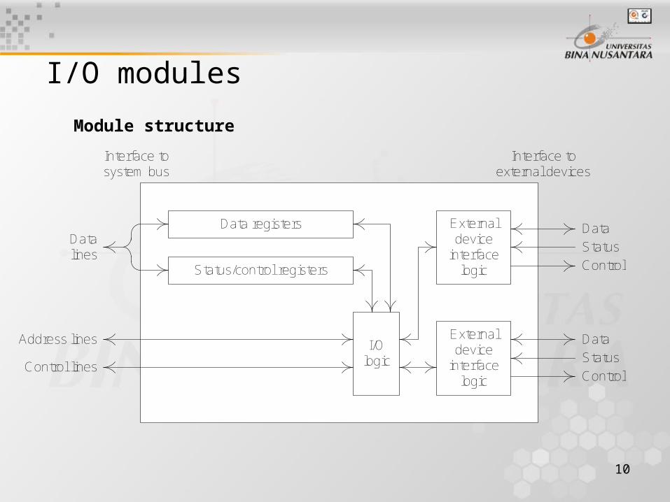
I/O modules
Module structure
Data registers
Status/control registers
I/Ologic
Externaldevice
interfacelogic
Externaldevice
interfacelogic
Data
Status
Control
Data
Status
Control
Datalines
Address lines
Control lines
Interface tosystem bus
Interface toexternal devices

11
Programmed I/O
No interrupts Use of interrupts
I/O to memory transfer through processor
Programmed I/O Interrupt driven I/O
I/O to memory transferDirect memory access
(DMA)
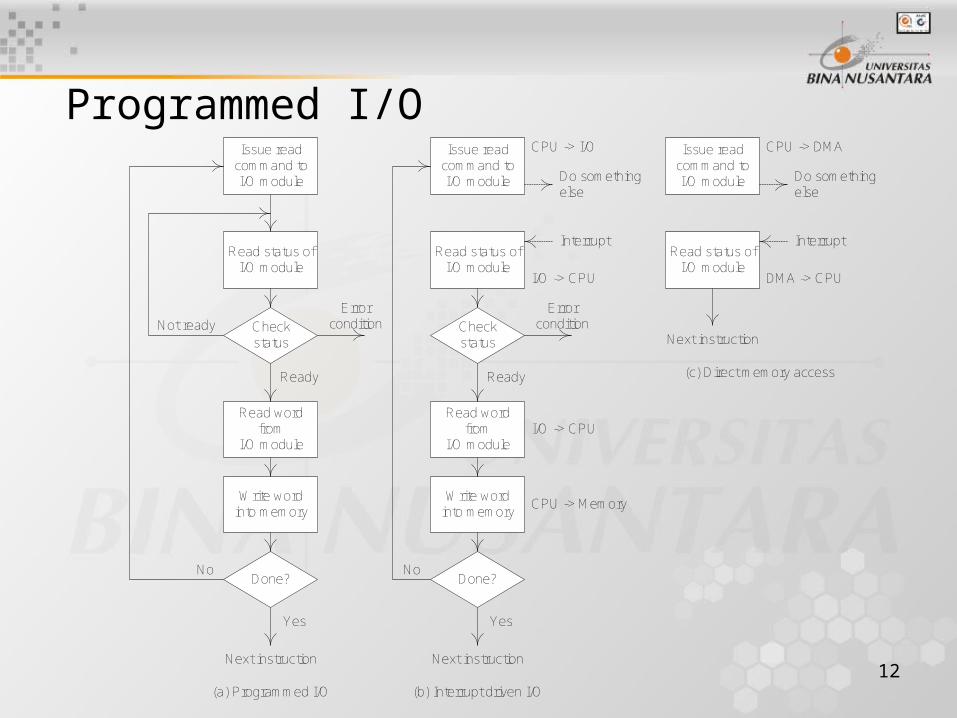
12
Programmed I/OIssue read
command toI/O module
Read status ofI/O module
Checkstatus
Read wordfrom
I/O module
Write wordinto memory
Done?
Not readyError
condition
Ready
No
Yes
Next instruction
Issue readcommand toI/O module
Read status ofI/O module
Checkstatus
Read wordfrom
I/O module
Write wordinto memory
Done?
Errorcondition
Ready
No
Yes
Next instruction
CPU -> I/O
Do somethingelse
Interrupt
I/O -> CPU
I/O -> CPU
CPU -> Memory
Issue readcommand toI/O module
Read status ofI/O module
CPU -> DMA
Do somethingelse
Interrupt
DMA -> CPU
Next instruction
(a) Programmed I/O (b) Interrupt driven I/O
(c) Direct memory access
13
There are four types of I/O commands:
1. Control
2. Test
3. Read
4. Write
Programmed I/O
I/O Commands
14
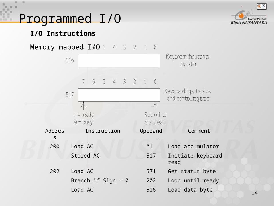
Programmed I/OI/O Instructions
7 6 5 4 3 2 1 0
7 6 5 4 3 2 1 0
516
517
Keyboard input dataregister
Keyboard input statusand control register
1 = ready0 = busy
Set to 1 tostart read
Address Instruction Operand
Comment
200 Load AC “1” Load accumulator
Stored AC 517 Initiate keyboard read
202 Load AC 571 Get status byte
Branch if Sign = 0 202 Loop until ready
Load AC 516 Load data byte
Memory mapped I/O

15
Programmed I/OI/O Instructions
Address Instruction Operand Comment
200 Load I/O 5 Initiate keyboard read
201 Test I/O 5 Check for completion
Branch Not Ready 201 Loop until complete
In 5 Load data byte
Isolated I/O

16
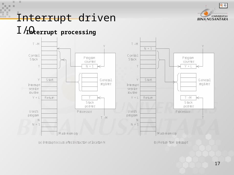
Interrupt driven I/OInterrupt processing
Device controller orother system hardware
issue an interrupt
Processor finishesexecution of current
instruction
Processor signalsacknowledgment of
interrupt
Processor push PSW andPC onto control stack
Processor loads new PCvalue based on interrupt
Save remainder ofprocess state information
Process interrupt
Restore process stateinformation
Restore old PSW and PC
Hardware Software
17
T - M
T
Y
Y + L
N
N + 1
Start
Return
ControlStack
Interruptserviceroutine
User’sprogram
N + 1
Programcounter
Generalregister
T
Stackpointer
Y
T - M
Processor
Main memory
T - M
T
Y
Y + L
N
N + 1
Start
Return
ControlStack
Interruptserviceroutine
User’sprogram
Y + L
Programcounter
Generalregister
T - M
Stackpointer
Y
T
Processor
Main memory
N + 1
(b) Return from interrupt(a) Interrupt occurs after instruction at location N
Interrupt driven I/OInterrupt processing

18
Interrupt driven I/ODesign issue
1. Because there will almost invariably be multiple I/O module, how does the processor determine which device issued the interrupt?
2. If multiple interrupt have occurred, how does the processor decide which one to process?
Four general categories of technique are in common use:
1. Multiple interrupt lines
2. Software poll
3. Daisy chain (hardware poll, vectored)
4. Bus arbitration (vectored)

19
Intel 82C59A Interrupt Controller
IR0
IR1
IR2
IR3
IR4
IR5
IR6
IR7
INT
External device 00
External device 01
External device 07
Slave 8259Ainterrupt controller
IR0
IR1
IR2
IR3
IR4
IR5
IR6
IR7
INT
External device 08
External device 09
External device 15
Slave 8259Ainterrupt controller
IR0
IR1
IR2
IR3
IR4
IR5
IR6
IR7
INT
External device 56
External device 57
External device 63
Slave 8259Ainterrupt controller
IR0
IR1
IR2
IR3
IR4
IR5
IR6
IR7
INT
Master 8259Ainterrupt controller
INT
8086 processor

20
Intel 82C55A Programmable Peripheral Interface
Controllogic
address A0
lines A1
read
write
reset
chip select
8
+5 volt
groundpowersupply
8086data bus
8 88
4
4
8
A
CA
CB
B
databuffer
8 bitinternal bus
controlregister
databuffers
21
Direct Memory Access
Drawbacks of programmed and interrupt driven I/O
1. The I/O transfer rate is limited by the speed with which the processor can test and service a device.
2. The processor is tied up in managing an I/O transfer; a number of instructions must be executed for each I/O transfer.

22
Direct Memory Access
Data count
Data register
Addressregister
Control logic
DMA request
DMA acknowledge
Interrupt
Read
Write
Data lines
Address lines
Block diagram

23
Direct Memory Access
Processorcycle
Processorcycle
Processorcycle
Processorcycle
Processorcycle
Processorcycle
Fetchinstruction
Decodeinstruction
Fetchoperand
Executeinstruction
Store resultProcessinterrupt
Instruction cycle
DMA breakpoints DMA breakpoints
DMA and interrupt breakpoints during an instruction cycle

24
Direct Memory Access
Processor DMA I/O I/O Memory
(a) Single-bus, detached DMA
DMA
I/O I/O
MemoryProcessor
I/O
DMA
(b) Single-bus, integrated DMA-I/O
I/O I/O
MemoryProcessor
I/O
DMA
System bus
I/O bus
(c) I/O bus
Alternative DMA configuration

25
Direct Memory Access
The evolution of the I/O function
1. The CPU directly controls a peripheral device.
2. A controller or I/O module is added. The CPU uses programmed I/O without interrupts.
3. The same configuration as in step 2 is used, but now interrupts are employed.
4. The I/O module is given direct access to memory via DMA.
5. The I/O module is enhanced to become a processor in its own right, with a specialized instruction set tailored for I/O.
6. The I/O module has a local memory of its own and is, in fact, a computer in its own right.

26
Direct Memory Access
I/O channel architecture
Multiplexorchannel
I/Ocontroller
I/Ocontroller
I/Ocontroller
I/Ocontroller
nData andaddress channelto main memory
Control signalpath to CPU
Selectorchannel
I/Ocontroller
I/Ocontroller
nData andaddress channelto main memory
Control signalpath to CPU
(a) Selector
(b) Multiplexor
27
The external interfaceType of interface
One major characteristic of the interface is whether it is serial or parallel.
The I/O module must engage in a dialogue with the peripheral. In general, the dialogue for a write operation is as follows:
1. The I/O module sends a control signal requesting permission to send data.
2. The peripheral acknowledges the request.
3. The I/O module transfers data.
4. The peripheral acknowledges receipt of the data.
Key to the operation of an I/O module is an internal buffer that can store data being passed between the peripheral and the rest of the system. This buffer allows the I/O module to compensate for the differences in speed between the system bus and its external lines.

28
The external interfacePoint to point and multipoint configuration
The connection between an I/O module in a computer system and external devices can be either point to point or multipoint.