1-s2.0-s1369800114002303-main
TRANSCRIPT

Contents lists available at ScienceDirect
Materials Science in Semiconductor Processing
Materials Science in Semiconductor Processing 26 (2014) 374–378
http://d1369-80
n Corrnn CorE-m
mahdi.n
journal homepage: www.elsevier.com/locate/mssp
Short Communication
Electrochemical investigation of graphene/cerium oxidenanoparticles as an electrode material for supercapacitors
Mahdi Robat Sarpoushi a,n, Mahdi Nasibi a,b,nn, Mohammad Ali Golozar c,Mohammad Reza Shishesaz a, Mohammad Reza Borhani d, Sajad Noroozi a
a Technical Inspection Engineering Department, Petroleum University of Technology, Abadan 63187-14331, Iranb Health, Safety and Environment (HSE) Engineering Office, NIOPDC, Yazd Region, Yazd 89167-84395, Iranc Materials Science Engineering Department, Isfahan University of Technology, Isfahan 84156-83111, Irand Department of Materials Engineering, Malek Ashtar University of Technology, ShahinShahr, Isfahan, Iran
a r t i c l e i n f o
Keywords:Electronic materialsNanostructuresElectrical propertiesEnergy storageGrapheneCerium oxide nanoparticles
x.doi.org/10.1016/j.mssp.2014.04.03401/Crown Copyright & 2014 Published by E
esponding author. Tel: +98 991 55725460; faresponding author. Tel.: +98 911 3708480; faail addresses: [email protected] ([email protected] (M. Nasibi).
a b s t r a c t
Mechanisms of charge storage, stability, capacitance, morphology and response current ofgraphene/cerium oxide (CeO2) nanoparticles as an electrode material for electrochemicalcapacitors have been investigated. Electrochemical properties of the assembled electrodeswere studied using cyclic voltammetry (CV) and electrochemical impedance spectroscopy(EIS) techniques in 3 M NaCl, NaOH and KOH electrolytes. Scanning electron microscopy(SEM) is used to characterize the microstructure and the nature of prepared electrodes.SEM images confirm the layered structure (12 nm thickness) of the used graphene.The proposed electrode shows a maximum specific capacitance as high as 11.09 F g�1 inthe potential range between �0.55 and 0.3 (V vs. SCE) at scan rate of 5 mV s�1. Thecharge/discharge cycling test shows a good reversibility and confirms that capacitance willincrease after 500 cycles by 37%.
Crown Copyright & 2014 Published by Elsevier Ltd. All rights reserved.
1. Introduction
Energy is currently a vital global issue given the likelydepletion of current resources (fossil fuels) coupledwith the demand for higher-performance energy storagesystems [1]. Such systems require the advantages ofportability and energy efficiency whilst being environ-mental friendly [2,3]. Among different energy storagesystems electrochemical capacitors can provide highpower capabilities, excellent reversibility (90–95%) andlong cycle life (4105) and exhibit 20–200 times larger
lsevier Ltd. All rights reserv
x: +98 631 4423520.x: +98 631 4423520..R. Sarpoushi),
capacitance per unit volume or mass than conventionalcapacitors [4-6].
Depending on the electrode material and charge sto-rage mechanism, electrochemical capacitors are classifiedas electrochemical double layer capacitors and pseudoca-pacitors [7-10]. The electrochemical double layer capaci-tors arise from the charge separation at the electrode/electrolyte interfaces, whereas pseudocapacitors exhibitelectrochemical Faradic reactions between electrode mate-rial and electrolyte [11]. Transition metal oxides areconsidered to be the most suitable candidate materialsfor electrochemical capacitors. These stem from the highspecific capacitance coupled with low resistance resultingin a high specific power which makes them suitable forcommercial applications. Because of the direct and fasttransformation of Ce(III) and Ce(IV), CeO2 nanoparticlesmay be good candidate as an electrode material for
ed.

Fig. 1. Scanning electron microscopy image obtained from CeO2/graphene.
M.R. Sarpoushi et al. / Materials Science in Semiconductor Processing 26 (2014) 374–378 375
electrochemical capacitors [12]. In this paper, mechanicalpressing as a fast and easy method was used to fabricatethe electrodes. Then, prepared nanocomposites were eval-uated as a novel electrode material for electrochemicalcapacitors using cyclic voltammetry (CV), electrochemicalimpedance spectroscopy (EIS) and scanning electronmicroscopy (SEM) techniques.
2. Experimental
2.1. Materials
High purity (99.98%) cerium oxide nanoparticles(10–30 nm) were purchased from US-nano, USA, graphenenanoflakes (60 nm, multi-layered) with a purity of 98.5%from graphene supermarket, USA and polytetrafluoroethy-lene (o2 μm) from Aldrich, USA. All other chemicals usedin this study were purchased from Merck, Germany.The mixture containing 15 wt% CeO2, 75 wt% grapheneand 10 wt% polytetrafluoroethylene (PTFE) was well mixedusing ultrasonic in ethanol bath and in a paste form for60 min. Paste form was chosen for better dispersion ofcerium oxide nanoparticles between graphene nanoflakes.After drying and powdering, the prepared composite waspressed onto a 316 L stainless steel plate (5�107 Pa)which was served as a current collector (surface area was1.22 cm2). A steel rod and hollow cylinder of epoxy wasused for pressing and a Teflon paper was used as aseparator at the bottom of the rod during pressing. Thetypical mass load of electrode material was 45 mg. 3 MNaCl, NaOH and KOH solution was used as electrolyte.
2.2. Characterization
The electrochemical behavior of prepared nanocompo-sites was characterized using CV and EIS tests. Electro-chemical measurements were performed using AutolabPGSTAT 302N (Netherlands). CV tests were performedwithin the range of �0.55 and þ0.3 V (vs. SCE), usingscan rates of 5, 10, 20, 30, 40, 50, 100, 200, 300, 400 and500 mV s�1. EIS measurements were also carried out infrequency range of 100–0.02 Hz at open circuit potentialwith an AC amplitude of 10 mV. For better understandingthe effect of the surface morphology and its nature on thecharge storage and charge delivering capability of pre-pared electrodes scanning electron microscope (TESCAN,USA) was used.
3. Result and discussion
Graphene with flake morphology and very close inter-layer distances has a high specific surface area which madeit suitable as an electrode material for supercapacitors.Fig. 1 shows the surface morphology of the preparedgraphene/cerium oxide nanocomposite. Perpendicular tothese nanoflakes it shows no porosity and is completelyflat. Fig. 1 confirms that the used material is completelyporous in 2D and will be flat in 1D. With this morphology,it seems the charge storage depends directly on the chargeseparation on the upper part (which is the most accessiblesurface of the electrode) and on open pore systems (which
are ion-size-dependent and less accessible) simulta-neously. Ion size, ion diffusion and electron transfer sitesthrough these pores would affect the activation of theseless accessible surfaces, especially at high scan rates.Although high molarities (3 M NaOH, KOH and NaCl ) ofthese electrolytes can be used but ion mobilities throughthe nanopores may be decreased and have adverse effecton the capacitance. Increasing the ionic radius woulddecrease the number of adsorbed ions on the unit surfacearea of the electrode and would decrease the stored chargeon the outer Helmholtz layer. The main difference of theseelectrolytes is the effective radius of their anions andcations. Naþ , Kþ , Cl�and OH� ions have effective radiusesof 102, 138, 181 and 153 pm, respectively. Therefore theratio of interlayer distance of the used graphene (3.36 Å) toionic radius (α) of these ions would be 3.29, 2.43, 1.86and 2.20.
The specific surface area of graphene nanoflakes is highenough for the large accumulation of ions but very closeinterlayer distances (3.63 Å) will limit ions diffusion tothese site. By adding CeO2 particles, flat surface of theelectrode becomes nearly porous; therefore, the specificsurface area of the electrode increases. The CeO2 quasi-spherical particles could be homogeneously dispersedacross the surface of the graphene nanoflakes, thuspreventing the CeO2 particles from agglomeration andwill effectively accommodate the volume change of CeO2
during the charge–discharge process (Fig. 1). Graphenenanosheets possess a high electronic conductivity, whichkeeps the dispersed CeO2 quasi-spheres connected anddecreases the contact resistance of the active material inthe electrode [13]. As shown in Fig. 2, bare CeO2 showedhigh solution resistance and low charge transfer resistancein 3 M NaCl electrolyte which was improved by theaddition of conductive materials such as graphene. Fig. 3
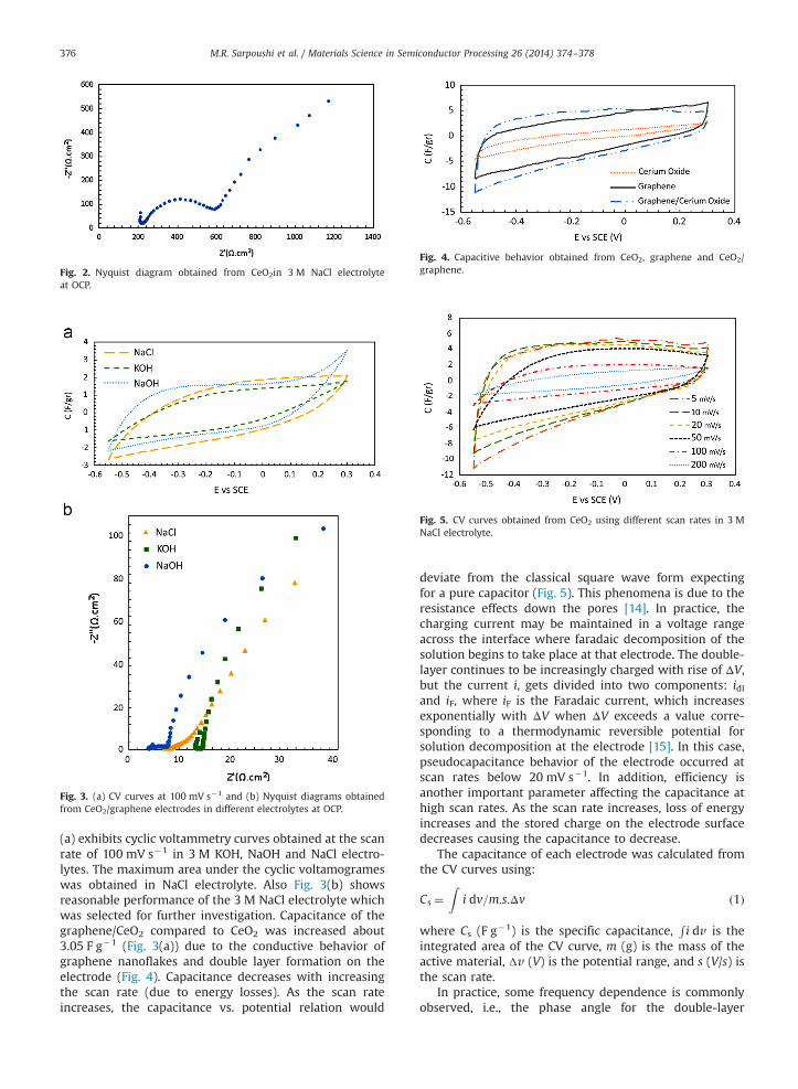
Fig. 2. Nyquist diagram obtained from CeO2in 3 M NaCl electrolyteat OCP.
Fig. 3. (a) CV curves at 100 mV s�1 and (b) Nyquist diagrams obtainedfrom CeO2/graphene electrodes in different electrolytes at OCP.
Fig. 4. Capacitive behavior obtained from CeO2, graphene and CeO2/graphene.
Fig. 5. CV curves obtained from CeO2 using different scan rates in 3 MNaCl electrolyte.
M.R. Sarpoushi et al. / Materials Science in Semiconductor Processing 26 (2014) 374–378376
(a) exhibits cyclic voltammetry curves obtained at the scanrate of 100 mV s�1 in 3 M KOH, NaOH and NaCl electro-lytes. The maximum area under the cyclic voltamogrameswas obtained in NaCl electrolyte. Also Fig. 3(b) showsreasonable performance of the 3 M NaCl electrolyte whichwas selected for further investigation. Capacitance of thegraphene/CeO2 compared to CeO2 was increased about3.05 F g�1 (Fig. 3(a)) due to the conductive behavior ofgraphene nanoflakes and double layer formation on theelectrode (Fig. 4). Capacitance decreases with increasingthe scan rate (due to energy losses). As the scan rateincreases, the capacitance vs. potential relation would
deviate from the classical square wave form expectingfor a pure capacitor (Fig. 5). This phenomena is due to theresistance effects down the pores [14]. In practice, thecharging current may be maintained in a voltage rangeacross the interface where faradaic decomposition of thesolution begins to take place at that electrode. The double-layer continues to be increasingly charged with rise of ΔV,but the current i, gets divided into two components: idland iF, where iF is the Faradaic current, which increasesexponentially with ΔV when ΔV exceeds a value corre-sponding to a thermodynamic reversible potential forsolution decomposition at the electrode [15]. In this case,pseudocapacitance behavior of the electrode occurred atscan rates below 20 mV s�1. In addition, efficiency isanother important parameter affecting the capacitance athigh scan rates. As the scan rate increases, loss of energyincreases and the stored charge on the electrode surfacedecreases causing the capacitance to decrease.
The capacitance of each electrode was calculated fromthe CV curves using:
Cs ¼Z
i dv=m:s:Δv ð1Þ
where Cs (F g�1) is the specific capacitance,Ri dv is the
integrated area of the CV curve, m (g) is the mass of theactive material, Δv (V) is the potential range, and s (V/s) isthe scan rate.
In practice, some frequency dependence is commonlyobserved, i.e., the phase angle for the double-layer

M.R. Sarpoushi et al. / Materials Science in Semiconductor Processing 26 (2014) 374–378 377
capacitance may not have the ideal value of 901 at allfrequencies, and potential dependence DC leakage can alsooccur. Deviation from ideal capacitative behavior can arisewhen there is some dielectric loss associated with thesolvent orientation polarization in the double-layer dielec-tric (at very high frequency) and/or when there are someslow anionic chemisorption processes that lead to lowerfrequency losses. In either case, there is energy dissipationin the charging and discharging cycles at an incompletelypolarizable electrode interface. Another source of nonidealbehavior is distribution of the double-layer capacitanceover a porous electrode surface. In a practical electroche-mical capacitor device, frequency dependence of the over-all capacitance is generally observed and is due, inaddition, to the “porous electrode” effect, to coupling withother equivalent series resistance (ESR) components [15].The efficiency of an electrochemical capacitor is related tothe loss factor, dc [16]:
dc ¼ tan ðδÞ ¼ tan ð901�φÞ ð2Þ
The power dissipated as heat in the internal resistanceis determined by the cosine of φ. The minimum loss factorof 0.492 (φ¼71.361) is achieved for the CeO2/grapheneelectrode at a frequency of 20 mHz (Fig. 6). The equivalentcircuit of the CeO2/graphene electrode is shown in Fig. 7.The equivalent circuit contains the bulk solution resistanceelement (Rs), the constant phase element (Q1) which isparallel with Charge transfer resistance (Rct), a Warburgdiffusion element (W) attributed to the diffusion of ions,and the low frequency capacitance (Q2), which is inparallel with (Rl), the leakage resistance. Table 1 shows
Fig. 6. (a) Bode plot obtained from CeO2/graphene electrode in 3 M NaClelectrolyte at OCP.
Fig. 7. Equivalent circuit of CeO2/graphene electrode in 3 M NaCl elec-trolyte at OCP.
Table 1Electrochemical parameters obtained from electrochemical impedance spectros
Rs (Ω) Q1 (S.sec0.912), n Rct (Ω) W
8.351 0.084, 0.912 732 1
numerical values for the equivalent circuit of CeO2/gra-phene electrode.
In charge and discharge cycles, total charge can bewritten as the sum of an inner charge from the less and anouter charge from the more accessible reaction sites, i.e.,qnT¼qnIþqnO, where qnT, qnI and qnO are the total chargeand charges related to inner and outer surface, respec-tively [18]. Extrapolation of qn to s¼0 from 1/qn vs. s1/2 plot(Fig. 8(a)) gives total charge qnT which is charge related tothe entire active surface of electrode. In addition, extra-polation of qn to s¼1 (s�1/2¼0) from qn vs. s�1/2 plot(Fig. 8(b)) gives the outer charge qnO, which is charged onthe most accessible active surface. Prepared electrodesshow the ratio of outer to total charge (qnO/qnT) of 0.084in NaCl electrolyte which confirms the low currentresponse on voltage reversal.
The cycle stability was evaluated by repeating the CV ata scan rate of 100 mV s�1 for 500 cycles. Prepared electro-des were found to exhibit excellent stability over the entirecycles. It is very interesting that the anodic and cathodiccurrents increased after 500 cycles as well as the cyclicvoltammetry curves remained in their rectangular-shapedprofiles (Fig. 9(a)).The charge stored on the electrode after500 cycles increased by 37% which may be used to thelarge amount of oxygen vacancies within the cerium oxideformed during reduction conditions [17]. Some of thecerium (IV) oxide is also reduced to cerium (III) oxide
copy measurement from graphene/cerium oxide nanoparticle electrodes.
(S.sec0.5) Q2 (S.sec0.25), n Rl (Ω)
09.8 0.123, 0.250 6.436�106
Fig. 8. Extrapolation of q to ν¼0 from the q�1 vs. ν0.5 plot given the totalcharge and (b)extrapolation of q to ν¼1 from the q vs. ν�0.5 plot giventhe outer charge for CeO2/graphene electrode.

Fig. 9. (a) CV curves obtained at 100 mV s�1and, and (b) Nyquist plotsafter different cycles for CeO2/graphene in 3 M NaCl electrolyte at OCP.
M.R. Sarpoushi et al. / Materials Science in Semiconductor Processing 26 (2014) 374–378378
under these conditions, which consequently increases theelectronic conductivity of the material. Therefore increas-ing the conductivity of the proposed material may be anacceptable reason of increasing the capacitance after 500cycles. EIS tests were used to evaluate the electrodechanges (Fig. 9(b)). This behavior confirmed by EIS evalua-tions. During the 500 charge/discharge cycles, the equiva-lent series resistance decreased (Fig. 9(b)) and Nyquistplots shifted a little toward slower values.
4. Conclusion
Studies confirmed the presence of flat and poroussurfaces, simultaneously, and it seems the charge storagedepends directly on the charge separation and Faradicreactions on the surface of the electrode. Also, charge/discharge process changed partly the CeO2 particles struc-ture which act as a pseudo-material from CeO2 to Ce2O3.Prepared electrode showed a low ratio of the outer chargeto total charge (qO/qT) of 0.084 which confirms the lowcurrent response on voltage reversal. Proposed electrodesshowed a maximum capacitance of as high as 11.09 F g�1
at 5 mV s�1 in 3 M NaCl electrolyte and exhibit excellentstability over the first 500 cycles (charge storage abilityincrease 37% after 500 cycles).
References
[1] K. Zhang, L.L. Zhang, X.S. Zhao, J. Wu, Chem. Mater. 22 (2010)1392–1401.
[2] S.M. Paek, E. Yoo, I. Honma, Nano Lett. 9 (2009) 72–75.[3] L Dong, R.R.S. Gari, Z. Li, M.M. Craig, S. Hou, Carbon 48 (2010)
781–787.[4] C. Chen, D. Zhao, X. Wang, Mater. Chem. Phys. 97 (2006) 156–161.[5] Y. Zhang, Y. Gui, X. Wu, H. Feng, A. Zhang, L. Wang, et al., Int.
J. Hydrog. Energy 34 (2009) 2467–2470.[6] L. Qu, Y.J.B. Baek, L. Dai, ACS Nano 4 (2010) 1321.[7] K.S. Novoselov, A.K. Geim, S.V. Morozov, D. Jiang, Y. Zhang, S.
V. Dubonos, I.V. Grigorieva, A.A. Firsov, Science 306 (2004) 666–669.[8] K.S. Novoselov, A.K. Geim, S.V. Morozov, D. Jiang, M.I. Katsnelson,
I.V. Grigorieva, S.V. Dubonos, S. Ardizzone, G. Fregonara, S. Trasatti,Electrochim. Acta 35 (1990) 263–267.
[9] A.K. Geim, K.S. Novoselov, Nat. Mater. 6 (2007) 183–191.[10] A.K. Geim, Science 324 (2009) 1530–1534.[11] D.D. Zhao, S.J. Bao, W.J. Zhou, H.L. Li., Electrochem. Commun. 9
(2007) 869–874.[12] G. Wang, J. Bai, Y. Wang, Z. Ren, J. Baic, Scr. Mater. 6 (2011) 339–342.[13] F. Zhou, X. Zhao, H. Xu, C. Yuan, J. Phys. Chem. C 111 (2007)
1651–1657.[14] S. Ardizzone, G. Fregonara, S. Trasatti, Electrochim. Acta 35 (1990)
263–267.[15] B.E. Conway, Electrochemical Capacitors Scientific Fundamental and
Technological Applications, Kluwer Academic/Plenum, New York,1999.
[16] R. Kotz, M. Carlen, Electrochim. Acta 45 (2000) 2483–2498.[17] M. Itagaki, S. Suzuki, I. Shitanda, K. Watanabe, H. Nakazawa, J. Power
Sources 164 (2007) 415–424.[18] I. Danaee, M. Jafarian, F. Forouzandeh, F. Gobal, MG. Mahjani, Int. J.
Hydrog. Energy 34 (2009) 859–869.