1 special topics in computer science computational modeling for snake-based robots computer-aided...
TRANSCRIPT

1
Special Topics in Computer ScienceComputational Modeling for
Snake-Based Robots
Computer-Aided Design Crash Course
Week 1, Lecture 2
William Regli
Geometric and Intelligent Computing Laboratory
Department of Computer Science
Drexel Universityhttp://gicl.cs.drexel.edu

2
Building Multidisciplinary Model
• Class Goal: create multidisciplinary engineering models
• Challenge: Learn enough about each discipline to create integrated models!
• Today: The role of 3D models and CAD

3
Computer Aided Design: A Brief History
• In The Beginning…1963Ivan Sutherland’sSketchpad
• Modified oscilloscope for drawing
• The original CAD system
Courtesy Marc Levoy @ Stanford U

4
History of the 3D graphics industry
• 1960s: – Line drawings, hidden lines, parametric surfaces (B-splines…) – Automated drafting & machining for car, airplane, and ships manufacturers
• 1970’s: – Mainframes, Vector tubes (HP…)– Software: Solids, (CSG), Ray Tracing, Z-buffer for hidden lines
• 1980s: – Graphics workstations ($50K-$1M): Frame buffers, rasterizers , GL, Phigs– VR: CAVEs and head-mounted displays– CAD/CAM & GIS: CATIA, SDRC, PTC– Sun, HP, IBM, SGI, E&S, DEC
• 1990s: – PCs ($2K): Graphics boards, OpenGL, Java3D– CAD+Videogames+Animations: AutoCAD, SolidWorks…, Alias-Wavefront– Intel, many board vendors
• 2000s:– Laptops, PDAs, Cell Phones: Parallel graphic chips– Everything will be graphics, 3D, animated, interactive– Nvidia, Sony, Nokia

5
Buzzword Deconfliction
• Computer Aided Geometric Design (CAGD): Curves/surfaces• Solid Modeling: Representations and Algorithms for solids• Computational Geometry: Provably efficient algorithms• Computer-Aided Design (CAD): Automation of Shape Design• Computer-Aided Manufacturing (CAM): NC Machining• Finite Element Meshing (FEM): Construction and simulation• Animation: Capture, Design, Simulation of shape behavior• Visualization: Graphical interpretations of (large) nD datasets• Rendering: Making (realistic) pictures of 3D geometric shapes• Image-Based Rendering (IBR): Mix images and geometry• Computer Vision: Reconstruction of 3D models from images• Reverse Engineering: Fitting surfaces to scanned 3D points• Virtual Reality (VR): Immersion in interactive environments• Augmented Reality (AR): Track and mark-up what you see

6
What is CAD?
• Primary authoring tool for the geometry and topology data associated with a product (plan, train, auto, building, etc)
• CAD software is central to Product Lifecycle Management and is often integrated with manufacturing, analysis, simulation and other engineering and business functions

7
Different Aspects of CAD

8
2D Graphics
• Raster:
Pixels– X11 bitmap, XBM– X11 pixmap, XPM– GIF– TIFF– PNG– JPG
Lossy, jaggies when transforming, good for photos.
• Vector:
Drawing instructions– Postscript– CGM– Fig– DWG
Non-lossy, smooth when scaling, good for line art and diagrams.

9
Representing 3D Objects
• Approximate– Facet / Mesh
• Just surfaces
– Voxel• Volume info
• Exact– Wireframe– Parametric
Surface– Solid Model
• CSG• BRep• Implicit Solid
Modeling
10
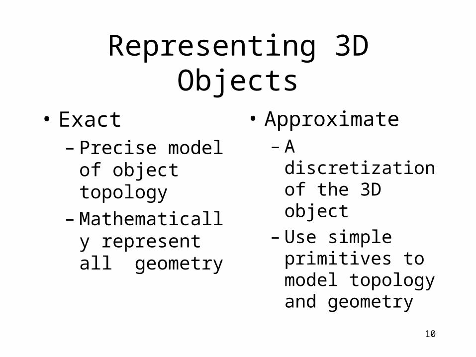
Representing 3D Objects
• Exact– Precise model of
object topology– Mathematically
represent all geometry
• Approximate– A discretization of
the 3D object– Use simple
primitives to model topology and geometry

11
Negatives when Representing 3D Objects
• Exact– Complex data structures– Expensive algorithms– Wide variety of formats,
each with subtle nuances– Hard to acquire data– Translation required for
rendering
• Approximate– Lossy– Data structure sizes can
get HUGE, if you want good fidelity
– Easy to break (i.e. cracks can appear)
– Not good for certain applications
• Lots of interpolation and guess work

12
Positives when Representing 3D Objects
• Exact– Precision
• Simulation, modeling, etc
– Lots of modeling environments
– Physical properties– Many applications (tool
path generation, motion, etc.)
– Compact
• Approximate– Easy to implement– Easy to acquire
• 3D scanner, CT
– Easy to render• Direct mapping to the
graphics pipeline
– Lots of algorithms
13
Two Major Types to Care About(for this class)
• Mesh-based representations
• Solid Models– As generated from CAD or modeling
systems

14
3D Mesh File Formats
Some common formats• STL
• SMF
• OpenInventor
• VRML

15
Minimal
• Vertex + Face
• No colors, normals, or texture
• Primarily used to demonstrate geometry algorithms
16
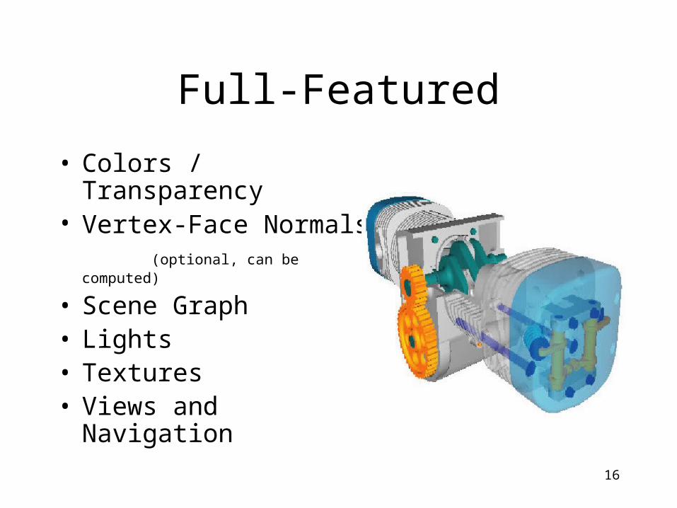
Full-Featured
• Colors / Transparency• Vertex-Face Normals
(optional, can be computed)
• Scene Graph• Lights• Textures• Views and Navigation
17
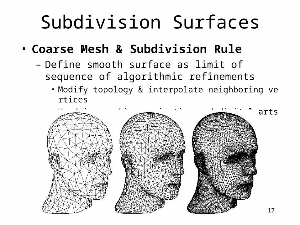
Subdivision Surfaces• Coarse Mesh & Subdivision Rule
– Define smooth surface as limit of sequence of algorithmic refinements
• Modify topology & interpolate neighboring vertices• Used in graphics, animation and digital arts applications
18
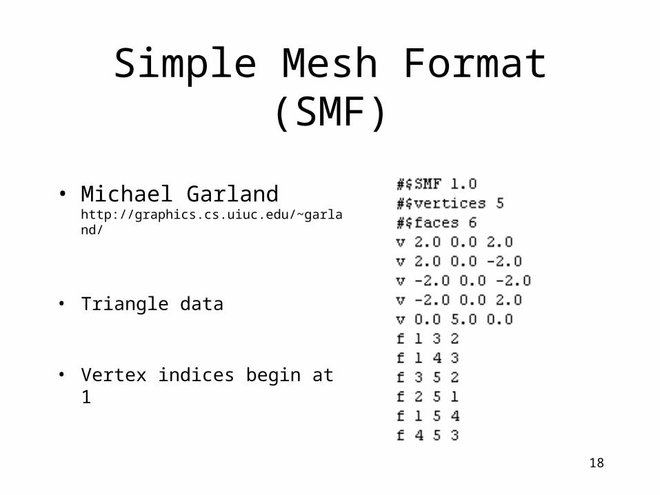
Simple Mesh Format (SMF)
• Michael Garland http://graphics.cs.uiuc.edu/~garland/
• Triangle data
• Vertex indices begin at 1

19
Stereolithography (STL)
• Triangle data +Face Normal
• The de-facto standard for rapid prototyping
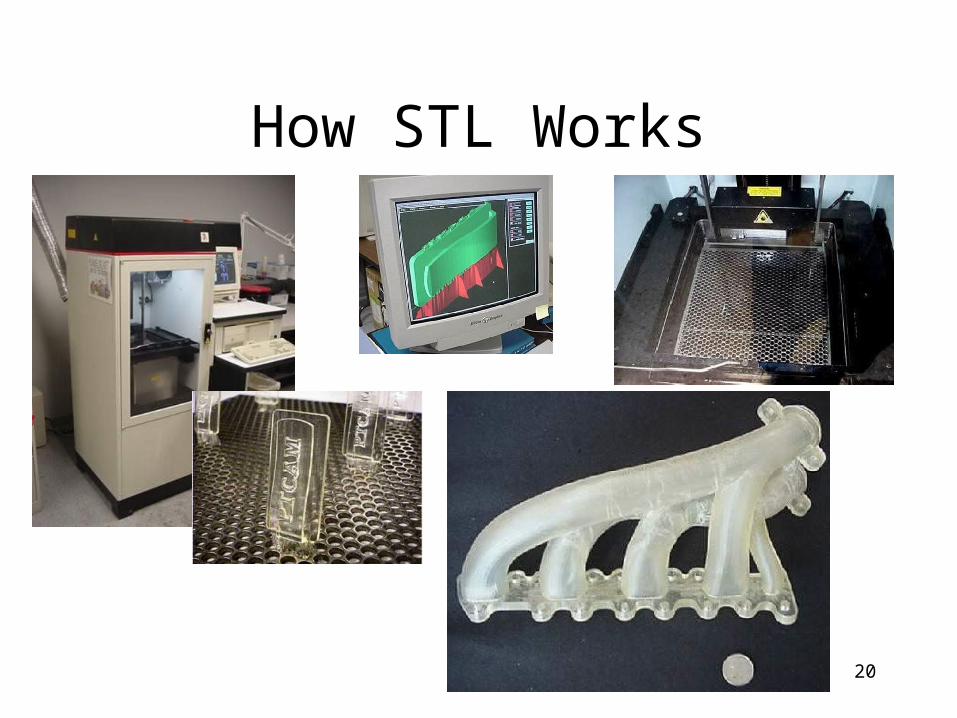
20
How STL Works

21
Open Inventor
• Developed by SGI• Predecessor to
VRML– Scene Graph

22
Virtual Reality Modeling Language (VRML)
• SGML Based
• Scene-Graph
• Full Featured

23
Issues with 3D “mesh” formats
• Easy to acquire
• Easy to render
• Harder to model with
• Error prone– split faces, holes, gaps, etc

24
Scanned DataFrom Exact
RepresentationSingle Scan360° Scan

25
How to scan (1)

26
How to scan (2)

27
Issues with Scanning
• Error and noise
• Time consuming– Lots of human editing required to create
clean models
• Models can be very large– Much larger than original BRep

28
Solid Models

29
3D solid model representations
• Implicit models • Super/quadrics• Blobbies• Swept objects• Boundary representations• Spatial enumerations• Distance fields• Quadtrees/octrees• Stochastic models

30
3D solid model representations
• Implicit models • Super/quadrics• Blobbies• Swept objects• Boundary representations• Spatial enumerations• Distance fields• Quadtrees/octrees• Stochastic models

31
Boundary Representation Solid Modeling
• The de facto standard for CAD since ~1987– BReps integrated into CAGD surfaces + analytic surfaces +
boolean modeling
• Models are defined by their boundaries• Topological and geometric integrity constraints are
enforced for the boundaries– Faces meet at shared edges, vertices are shared, etc.

32
Solids and Solid Modeling
• Solid modeling introduces a mathematical theory of solid shape– Domain of objects– Set of operations on the domain of objects– Representation that is
• Unambiguous• Accurate• Unique• Compact• Efficient

33
Solid Objects and Operations
• Solids are point sets– Boundary and interior
• Point sets can be operated on with boolean algebra (union, intersect, etc)
Foley/VanDam, 1990/1994

34
Solid Object Definitions
• Boundary points– Points where distance to the object and the
object’s complement is zero
• Interior points– All the other points in the object
• Closure– Union of interior points and boundary
points

35
Let’s Start Simple:Polyhedral Solid Modeling
• Definition– Solid bounded by
polygons whose edges are each a member of an even number of polygons
– A 2-manifold: edges members of 2 polygons

36
BRep Data Structure
• Vertex structure– X,Y,Z point– Pointers to n coincident edges
• Edge structure– 2 pointers to end-point vertices– 2 pointers to adjacent faces– Pointer to next edge– Pointer to previous edge
• Face structure– Pointers to m edges

37
BRep Data Structures
• Winged-Edge Data Structure (Weiler)
• Vertex– n edges
• Edge– 2 vertices– 2 faces
• Face– m edges
Pics/Math courtesy of Dave Mount @ UMD-CP

38
State of the Art: BRep Solid Modeling
• … but much more than polyhedra
• Two main (commercial) alternatives– All NURBS, all the time
• Pro/E, SDRC, …
– Analytic surfaces + parametric surfaces + NURBS + …. all stitched together at edges
• Parasolid, ACIS, …

39
Issues in Boundary Representation Solid Modeling• Very complex data structures
– NURBS-based winged-edges, etc
• Complex algorithms– manipulation, booleans, collision detection
• Robustness• Integrity• Translation• Features• Constraints and Parametrics

41
Issues with 3D Set Operations
• Ops on 3D objects can create “non-3D objects” or objects with non-uniform dimensions
• Objects need to be “Regularized”– Take the closure of the interior
Foley/VanDam, 1990/1994
Input set Closure Interior Regularized

42
Regularized Boolean Operations
• 3D Example– Two solids A and B– Intersection leaves a
“dangling wall”• A 2D portion hanging
off a 3D object
– Closure of interior gives a uniform 3D result
Pics/Math courtesy of Dave Mount @ UMD-CP

43
Boolean Operations
• Other Examples:• (c) ordinary
intersection• (d) regularized
intersection– AB - objects on the
same side– CD objects on
different sides
Foley/VanDam, 1990/1994

44
Boolean Operations
Foley/VanDam, 1990/1994

45
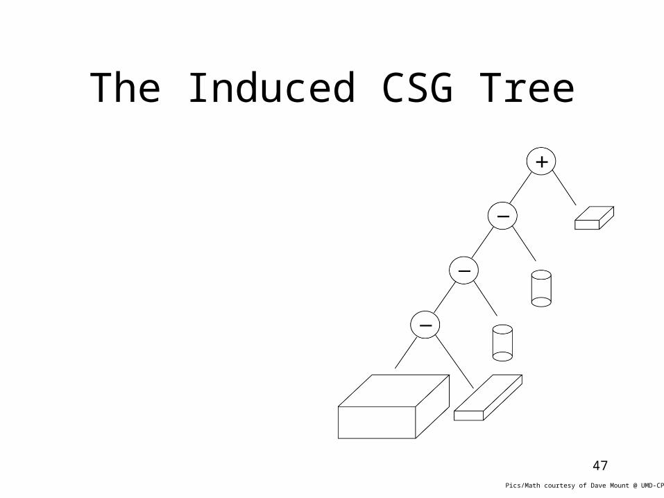
Constructive Solid Geometry (CSG)
• A tree structure combining primitives via regularized boolean operations
• Primitives can be solids or half spaces

46
A Sequence of Boolean Operations
• Boolean operations • Rigid transformations
Pics/Math courtesy of Dave Mount @ UMD-CP
47
The Induced CSG Tree
Pics/Math courtesy of Dave Mount @ UMD-CP

48
The Induced CSG Tree
• Can also be represented as a directed acyclic graph (DAG)
Pics/Math courtesy of Dave Mount @ UMD-CP

49
Issues with Constructive Solid Geometry
• Non-uniqueness
• Choice of primitives
• How to handle more complex modeling?– Sculpted surfaces? Deformable objects?

50
Issues with Constructive Solid Geometry
• Non-Uniqueness– There is more than
one way to model the same artifact
– Hard to tell if A and B are identical

51
Issues with CSG
• Minor changes in primitive objects greatly affect outcomes
• Shift up top solid face
Foley/VanDam, 1990/1994
52
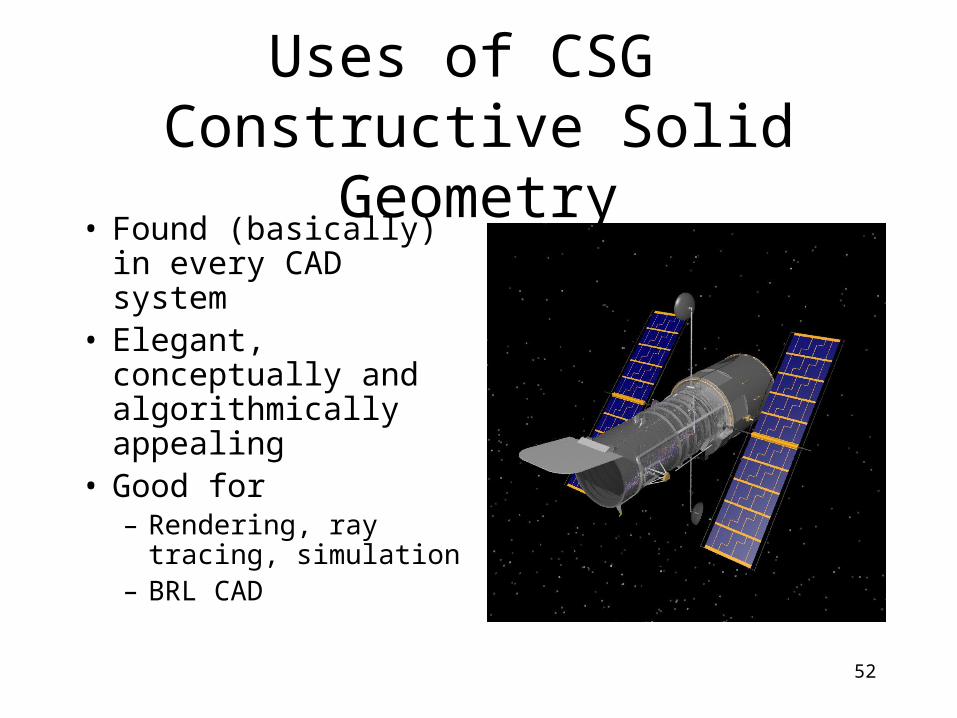
Uses of CSG Constructive Solid Geometry
• Found (basically) in every CAD system
• Elegant, conceptually and algorithmically appealing
• Good for– Rendering, ray
tracing, simulation– BRL CAD

53
CAD: Feature-Based Design
• CSG is the basic machinery behind CAD features
• Features are– Local modifications to
object geom/topo with engineering significance
– Often are additive or subtractive mods to shape
• Hole, pocket, etc…

54
Parametric Modeling in CAD
Foley/VanDam, 1990/1994
• Feature relationships• Constraints

55
CAD Formats

56
Common CAD Formats
• Standards– STEP (ISO 103033)– IGES
• Industry– Solid Model (mostly just geom/topo)
• ACIS .sat, Parasolid .xmt, OpenCascade
– CAD Model• Vendor specific

57
CAD Vendor Formats
• Pro/ENGINEER– .prt (part) and .asm (assembly)
• UG/SDRC– .mf1 (model file), .arc (archive), .xmt (transmit file)
• AutoCAD– DXF, DWG
• Bentley– DGN
• Etc etc
58
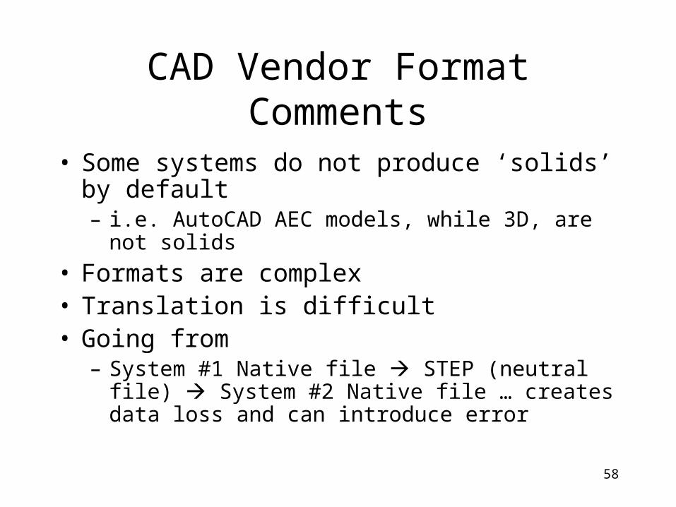
CAD Vendor Format Comments
• Some systems do not produce ‘solids’ by default– i.e. AutoCAD AEC models, while 3D, are not
solids
• Formats are complex• Translation is difficult• Going from
– System #1 Native file STEP (neutral file) System #2 Native file … creates data loss and can introduce error

59
A brief history
• IGES V1.0 was released in 1981, the current version V5.3 was released in 1996
– Geometry-based standard– Non-unique definition for many entities– Many IGES flavoring tools for repair
• STEP v1.0 was released in 1994– Product-based– Have not heard about “step flavoring” tools– An issue in both IGES and STEP: different CAD systems have different
tolerance, therefore a trim surface may become untrimmed after translation.
– A very popular application of IGES/STEP is not data translation, it is long term data retention.

60
IGES & STEP history
IGES v.1
IGES v5.3
STEP AP203
STEP AP203 E2
1980
2010
2000
1990
Multiple definitions for the same entity. Many IGES flavoring tools
CAD system tolerance issues
ParametricsNeed construction history, GD&T
Many commercial direct translators
A very successful application of IGES/STEP is long term data retention.
Full interoperability?

61
Getting CAD Model for Legos

62
CAD Systems
• Drexel is site licensed for MicroStation– https://software.drexel.edu
• Other tools available at GICL and MEM– I-DEAS– Pro/E– SolidWorks– AutoCAD
63
Spatial Occupancy Enumerations

64
Spatial Occupancy Enumeration
• Brute force– A grid
• Pixels– Picture elements
• Voxels– Volume elements
• Quadtrees– 2D representation
• Octrees– 3D representation– Extension of quadtrees

65
Brute Force Spatial Occupancy Enumeration
• Impose a 2D/3D grid– Like graph paper or
sugar cubes
• Identify occupied cells
• Problems– High fidelity requires
many cells
• “Modified”– Partial occupancy
Foley/VanDam, 1990/1994

66
Quadtree
• Hierarchically represent spatial occupancy
• Tree with four regions– NE, NW, SE, SW– “dark” if occupied
Foley/VanDam, 1990/1994
67
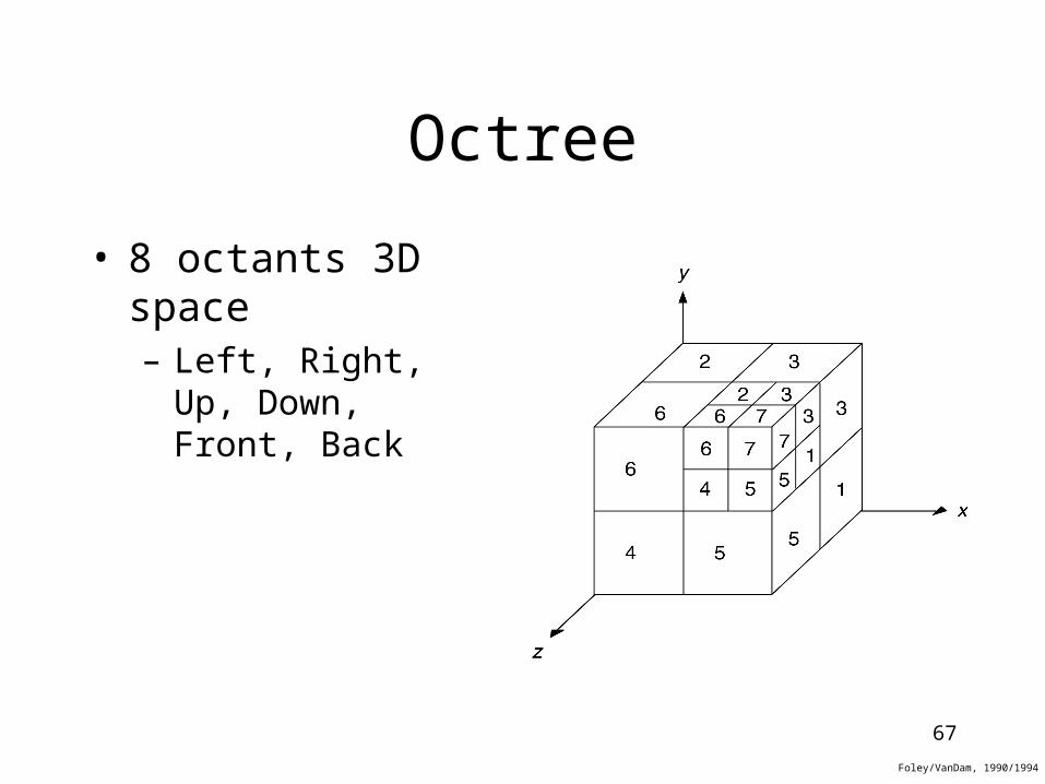
Octree
• 8 octants 3D space– Left, Right, Up,
Down, Front, Back
Foley/VanDam, 1990/1994

68
Applications for Spatial Occupancy Enumeration
• Many different applications– GIS– Medical– Engineering Simulation– Volume Rendering– Video Gaming– Approximating real-world
data– ….

69
Issues with Spatial Occupancy Enumeration
• Approximate– Kind of like faceting a surface, discretizing
3D space– Operationally, the combinatorics (as
opposed to the numerics) can be challenging
– Not as good for applications wanting exact computation (e.g. tool path programming)

70
END

71
MBD or Model Based Definition
• 3D model is the sole data authority
• No more 2D drawings
• The 3D model should contain everything needed from design to manufacturing, in particular, GD&T (Geometry Dimensions and Tolerance).
• Therefore we need GD&T in data translation
• STEP 203 E2 implementation will help

72
MBD – Model Based Definition
• Boeing is transitioning rapidly to a model based environment.
• Data Delivery to supplier must be formatted robustly and efficiently and in a standard open format.
• Data must be “purposed” to the downstream activity to protect IP and KBE.
• Relational design chains must be preserved for interoperability.
• Attribute and Meta data must be passed in a Xlation and purposed.
• New materials will bring new requirements for data exchange.

73
The Design Cycle
PROCESSPROCESS
DATADATAFORMATFORMAT
RREEQQ’’ss
TTOOOOLLSS
Process drives out requirements
Requirements are accommodated by data
structure
Data format enables the tool
Tools accomplish the process
INNOVATIOINNOVATION!N!

74
Feature-based translation
• Users expect translated model to be modifiable at the receiving site
• Feature-based translation or construction history or STEP AP203 E2
• Feature-reconstruction bypasses CAD system tolerance issues, however, it brings in another set of problems –
– There are many incompatible features between CAD systems
– There are many construction methods for the same feature on the same CAD system (e.g.hole)
– Different CAD system employs different algorithms to computer intersection curves, therefore, we need translation validation.
75
CAD Data Translation Validation• Users have been asking for it since Day 1.
• What to validate? Do you care about these changes?
– geometry or shape – topology – one sphere becomes two semi-spheres– entity count – math – exact representation of a circle by a NURBS spline– mass property– color changes– layer changes
• Challenges– Need to recognize that this is a new field – How to communicate changes to a general user in a “general” language?– Need a tool developed for this purpose

76
Factors influence the quality of data translation
• Design standards
• Design methodology
• Design quality control
• Release process with a model quality check

77
Design processes influence data translation needs
• paper drawing – no need for data translation
• 2D CAD drawing – dxf or IGES
• 3D CAD design – IGES or STEP
• 3D CAD solid design - STEP
• PLM – Product Lifecycle Management
• Data management is the center of the universe
Designers must go to PDM to get appropriate CAD models
• CAD is one of many tools within PLM
• CAD data translation must go with PDM
(CAD model + data maturity level + BOM + relational design…+etc)

78
CAD Data Translation Challenges
• CAD systems were design for CAD, not data translation• Data translation is a step-child of a CAD system• Do CAD vendors care about data translation?
• No, this is a step-child.• Yes, make sure it does not work well to export my data.
• STEP AP203 E2 implementation – How to get all major CAD vendors involved?

79
What we do not want to translate
• Company intellectual property embedded in CAD models
– KBE (Knowledge Based Engineering) data– Specific math formulas to create curves and surfaces– Third party application software data - engineering notes– in-house developed macros
• This is not a problem with current IGES, STEP or other direct translators. However, we are concerned with data exchange with suppliers in native CAD files such as CATIA V5 via a PDM system.

80
How does Boeing perform data translation?
• Point solution Xlators tailored for specific native formats are utilized at Boeing
• Healthy use of iges and STEP for exchange of data.
• Validation shares equal priority with Xlation
• Boeing has adopted a common native toolset from Dassault Systems’ as a go forward strategy.
• Process>Requirements>DataStructure>Tool,----} Paradigm
• Single source master definition, vaulted data, distributed and repurposed for the target downstream activity.
• Highly reusable data sets.

81
Introduction
• Past – STEP expectations not met, what has accomplished, weak areas, work arounds, etc.• Present – New standards evolving, current capabilities, limitations, work arounds, etc. • Future – Full relational design expectations, dreams,

82
Surface Models
• Basic idea:– Represent a model as a set of
faces/patches
• Limitations:– Topological integrity; how do faces “line
up”?; which way is ‘inside’/ ‘outside’?
• Used in many CAD applications– Why? They are fine for drafting and
rendering, not as good for creating true physical models

83
Implicit Solid Modeling
• Computer Algebra meets CAD
• Idea: – Represents solid as the set of points where an
implicit global function takes on certain value• F(x,y,z) < val
– Primitive solids are combined using CSG – Composition operations are implemented by
functionals which provide an implicit function for the resulting solid
From M.Ganter, D. Storti, G. Turkiyyah @ UW

84
Quadratic Surfaces
• Sphere
• Ellipsoid
• Torus
• General form
x 2 y 2 z2 r2
x
rx
2
y
ry
2
z
rz
2
1
r x
rx
2
y
ry
2
2
z
rz
2
1
ax 2 by 2 c z2 2 f yz 2gxz 2hxy 2px 2qy 2rz d 0

85
Superellipsoid Surfaces
• Generalization of ellipsoid
• Control parameters s1 and s2
• If s1 = s2 =1 then regular ellipsoid
• Has an implicit and parametric form!
s2
s1
x
rx
2 / s2
y
ry
2 / s2
s2 / s1
z
rz
2 / s1
1

86
CSG with Superquadrics

87
CSG with Superellipsoids

88
End