1 star tof calibration. 2 detectors tpc(tpx) - tracking mrpc tof (tofr) – stop time measurement...
TRANSCRIPT

1
STAR TOF Calibration

2
DetectorsTPC(TPX)- tracking
MRPC TOF (TOFr) – stop time measurement
pVPD/upVPD - start time measurement
Particle momentum; dE/dx
~8% resolution
/K separation to ~0.6GeV/c
k/p separation to ~1.0GeV/c
Aim at 100ps time resolution TOF system
/K separation to ~1.6GeV/c & k/p separation to ~3.0GeV/c
3
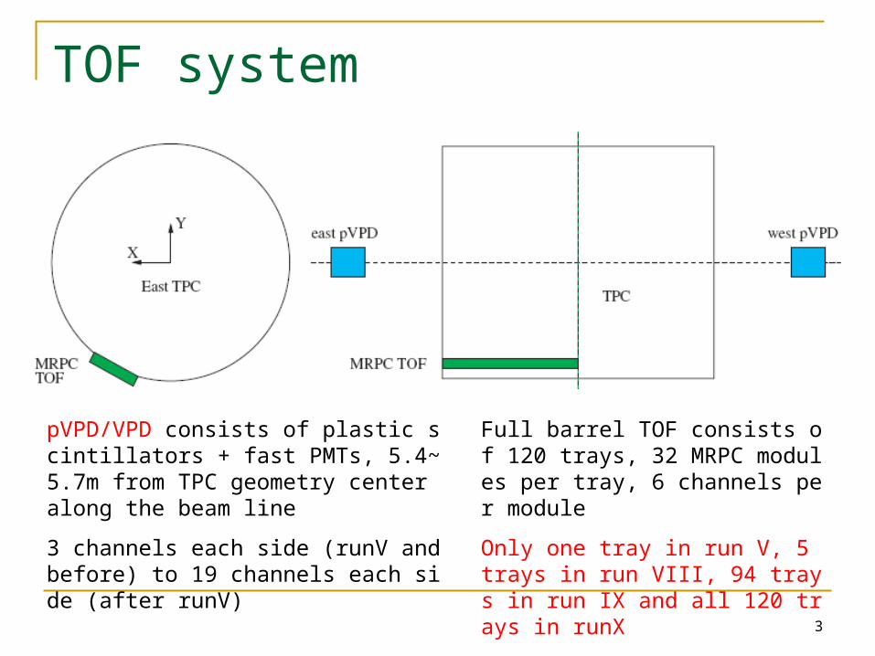
TOF system
pVPD/VPD consists of plastic scintillators + fast PMTs, 5.4~5.7m from TPC geometry center along the beam line
3 channels each side (runV and before) to 19 channels each side (after runV)
Full barrel TOF consists of 120 trays, 32 MRPC modules per tray, 6 channels per module
Only one tray in run V, 5 trays in run VIII, 94 trays in run IX and all 120 trays in runX

4
TOF Electronics
Start Detector
TOF Tray
TDIG TDIG
TCPU
DIFFERENTIAL DATA AND CLOCK
TINO TINO
MRPC MRPC
COMMANDS
48 CHAN
48 CHAN
48 CHAN
TRAY CAN BUS
MULTIPLICITY
THUB
COPPER: DATA, SAMPLE CLOCK, RESET TRIGGER STROBE & DATA
TOP LEVEL CAN BUS
COPPER LINKS TO 29 TRAYS
RHIC CLOCK
SIU FIBER
CAN BUS TO 29 TRAYS
TCD
DAQ
48 CHAN
4
L0 Trigger
4
PMTs TPMT TDIS TCPU
Diff. Data & Clk
Local CANbus
Co
pp
er:
Da
ta,
Sa
mp
le C
lk,
Re
set
Trg
Str
ob
e &
Da
ta
Reset & ClockFrom other THUBs
Reset & ClockTo other THUBs
2 THUB per side, 4 total 1 TCPU per tray/VPD, 122 total
1 TPMT/TDIS per VPD, 2 total8 TINO/TDIG per tray, 960 total
24 channel per TINO/TDIG, 23040 total

5
HPTDC INL CorrectionIntegral Non-Lineraity
Diffrential Non-Lineraity

6
update
Calibration results
Related software

7
TOF Calibration – runV (and later on)
Leading-edge timing signal, trailing-edge signal width (TOT)
time
Amp.
T1l T2l T2t T1t
Thre.
Time stamp
Leading-edge trigger, signal charge (ADC) is measured for correction
time
Amp.
T1 T2
Thre.
Q1
Q2

8
VPD
Collision Point
VPD PMTs •All hits in the same event arrived at the same time•As reference for each other

9
VPD calibration procedure

10
TDC-TOT correlation
Use spline fit (3rd polynomials TSplineFit based on ROOT, developed by François-Xavier Gentit)
Run VIII, 200 GeV ppRun V, 62.4 GeV CuCu
TD
C1 –
(T
DC
2+T
DC
3)/2
(n
s)
TOT (ns)TOT (ns)

11
Resolution before/after calibration
~6 ns ~0.16 ns
Bef
ore
cali
brat
ion
After
calibration
TDC1 – (TDC2+TDC3)/2 (ns)
TDC1 – (TDC2+TDC3)/2 (ns)
Run VIII200 GeV pp

12
Global offset tune• Slewing effect correction was done on east/west side separately• Absolute time from east/west side are floating• Tune the global offset between east/west side to match Vz(VPD) with Vz(TPC)
Beam line
Vertex Z
zT0+(L/2-Vz)/cT0+(L/2+Vz)/cWest East
upVPDupVPD
CP
1 1
( ) ( / / ) / 2e wi N j N
ei e wj wi j
Vz VPD t N t N c
1 1
( ) /e wi N j N
ei wj e wi j
starte w
t t N N Vz c
TN N

13
Choose sample by limiting dE/dx and momentum range (or pre-calibrated TOF)
T0 correction, different cable length and signal transition time
TOFr TOT and Z position calibration, using charged pion sample.
Iteration several times (if needed)
TOFr Calibration procedure
• Try channel-by-channel first• Not enough statistics? Then
try module-by-module, or board-by-board

14
T0 correction
TOFmeasured – TOFexpected (ns)
Com
ts
Channel-by-ChannelSimple Gaussian function FitShift the mean of TOFmeasured – TOFexpected to 0
Run VIII200 GeV pp

15
TOFr TOT slewing correction
Run V 200 GeV CuCuSignal ringing effect
Run VIII 200 GeV ppBetter signal termination achieved
TOT (ns)
TOT (ns)
TO
Fm
easu
red
– T
OF
exp
ecte
d (n
s)

16
Hit position (Z) corrction
TO
Fm
easu
red –
TO
Fex
pec
ted
(ns)
Hit Position Z (cm)
Run V 200 GeV CuCu
Run VIII 200 GeV pp
MRPC stripMRPC stripReadoutReadout
Finite signal propagation speed vs. hit position

17
TOF Time Resolution Run V CuCu 62.4GeV
Run V CuCu 200GeV
Run VIII pp 200GeV

18
TOF resolution summary
Operation conditionTime Resolution (ps)
pVPDTOFr
(overall)TOFr
(stop time)
Run III200GeV d+Au ~85 ~120 ~85
200GeV p+p ~140 ~160 ~80
Run IV
62GeV (Au+Au) ~55 ~105 ~89
200GeV (Au+Au)
FF/RFF ~27 ~74 ~70
HF ~20 ~74 ~71
Run V200GeV Cu+Cu (TOT) ~ 50 ~92 ~7562GeV Cu+Cu (TOT) ~ 82 ~125 ~94
Run VIII200 GeV d+Au NA NA NA
200 GeV p+p (TOT) ~83 ~112 ~75

19
Expectation (ideal)
TOF calibration w/o start detector
nTTtofZcorTOTcorTDCTn
i iiiii
10__
Fast simulation
TOF mean time resolution: 90ps
Time-TOT/Z correlation taken from run V CuCu data
T0 obtained by direct average of Ti
Several iteration of calibration

20
T0 w/o start detector – from data
expected) (as ps74~0
2ps74~0
T
nTTi
60ps) :(expected ps63~0
3ps89~0
T
nTTi
n
i i
n
i iiii tofZcorTOTcorTDCT1
2
1
2 __0
Run V 62.4 GeV CuCu
After 6-round calibration iteration
21
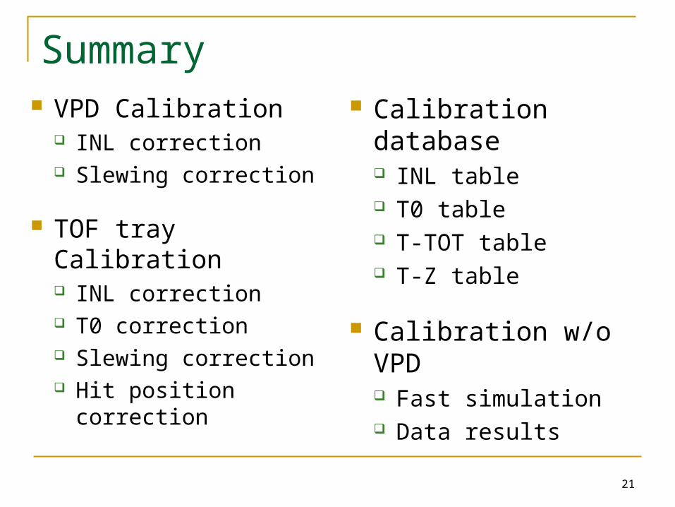
Summary VPD Calibration
INL correction Slewing correction
TOF tray Calibration INL correction T0 correction Slewing correction Hit position correction
Calibration database INL table T0 table T-TOT table T-Z table
Calibration w/o VPD Fast simulation Data results

22
Backup Slides

23
Output calibration parameter
• Inconvinient to retrieve and use the parameters of all of the Splines • Upload each TOT bin boundaries and the corresponding corrections• Interpolate in each TOT bin
Bin boundarySame statistics in each bin

24
#Events needed for calibration
Collisions <dNchraw/d>a
rXiv:
0808.2041
×1/4(pure pion)
×80% (match)
×2 ()
Useable hits per channel
#Events for
channel-by-
channel
#Events for
module-by-
module
#Events for
board-by-
board
#Events for T0
(500/channel
)
p+p (MB) 2.4 0.96 4.2e-5 240 M 40 M 10 M 12 M
d+Au(MB) 10.2 4.1 1.8e-4 56 M 9.3 M 2.3 M 2.8 M
Au+Au(MB) 200 80 3.5e-3 2.9 M 0.5 M 0.12 M 0.15 M
Au+Au
(0-10%)
515 206 8.9e-3 1.2 M 0.2 M 0.05 M 0.06 M
10 K for slewing correction
Note in pp collisions, the upVPD efficiency is only ~40% if requiring >=2 hits on both sides

25
VPD fired channels
• ~35% events have >=3 hits on either side (useable for calibration)• ~40% events have >=2 hits on both sides (better start time or • ~15% events have >=3 hits on both sides Vz resolution)
Run VIII200 GeV pp
Zebo Tang

26
Track projection and Vz correlation
2D DCA
Beam line uncalibrated, fix to (0.5,0) cmShould be different between fillsUnnecessary to parallel to z direction
Vertex from track projection (No vertex from TPX ): project tracks matched to TOF hits, get the closest position to beam line.

27
Calibration Procedure – before run V
Leading-edge trigger, signal charge (ADC) is measured for correction
time
Amp.
T1 T2
Thre.
Q1
Q2

28
pVPD Calibration – start time
xdx
c
x
baxf

29
TOFr Calibration – MRPC TA & TZ
TA slewing correction Hit position (TZ) correction
2x
e
xx
d
x
c
x
baxf
7th-order polynomial

30
Time resolution determination
332~
22~
0
321
21
nTTT
nTT
TTi 35.1~
22~
0
nT
nT
TT
i
i
i
Increase with n (assume equal time resolution for each channel)
320~3~
20~2~
0
nTTT
nTTT
T
ii
ii

31
Calibrated time resolution

32
Hadron PID

33
Electron PID
34
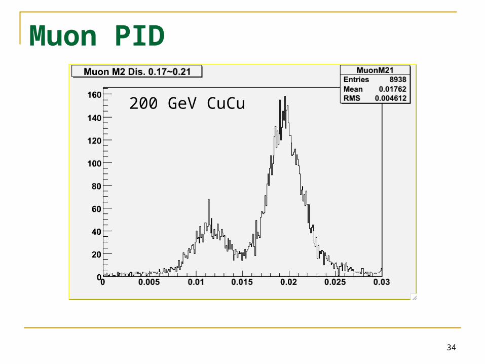
Muon PID
200 GeV CuCu

35
Run-VIII PID
1.2<p<1.4 GeV/c