1. task of this manual - ilec – ilec gmbh sn6900 onwards.pdf · 1. task of this manual ... rather...
TRANSCRIPT

1

2

3
1. TASK OF THIS MANUAL This manual gives all information required by the owner or user to understand all functions of the instrument, to install it, if necessary to program it, to maintain it, and finally, to use it in flight. It is not necessary to study this manual in an intensive way in order to be able to use the instrument. Rather superficial reading will enable the user to find a particular subject, later, with the help of the list of contents, in case there is a question. For the rest, the manual is written in a way to inform the interested user very thoroughly on the instrument, for him to draw a maximum of benefit from it Because the manufacturers are convinced that a good manual contributes substantially to the benefit a user will draw from an instrument, they have invested much effort and experience in this manual. The right place for this manual is the main file of the aircraft into which the instrument is installed. Ideally it should be made available to every pilot who uses the SB-8. Before installing the instrument, and under all circumstances before making any electrical connection, the chapter on installation must be read. Before any opening of the instrument the chapter on adjustments and programming must be read. Chapter 7 (The SB-8 variometer in flight) is thought as an annex for the more advanced and/or interested pilot. It has been written in such a thorough way because this matter is not being treated in the general literature on soaring. WARNING: This instrument is to help the pilot to plan his flight on the basis of data he has. It does not relieve him from his responsibility to control his aircraft in a safe way. Under no circumstances can the SB-8 replace an airspeed indicator or any other element of safe piloting. This manual is continuously being updated, and therefore up to our latest knowledge, as well as adapted to the latest technical state of the instrument. Accordingly it applies only to instruments with the serial numbers below, and at any rate to the instrument it has been delivered with. This manual applies to all standard instruments of the SB-8 type from serial number 6900 onwards.

4
State: March 1990
LIST OF CONTENTS 1. TASK OF THIS MANUAL....................................................................................................................................... 3 LIST OF CONTENTS ................................................................................................................................................... 4 2. Description of the System.......................................................................................................................................... 5
2.1. Principle of measurement.................................................................................................................................... 5 2.2. Variometer .......................................................................................................................................................... 5 2.3. Variometer audio generator ................................................................................................................................ 5 2.4. Speed command .................................................................................................................................................. 5 2.5. Audio generator of speed command ................................................................................................................... 6 2.6. Mode switching................................................................................................................................................... 6 2.7. Indicators ............................................................................................................................................................ 6 2.8. Distance- and Final glide computer .................................................................................................................... 8 2.9. Precision.............................................................................................................................................................. 8
3. INSTALLATION ...................................................................................................................................................... 9 3.1. Unpacking, packaging......................................................................................................................................... 9 3.2. Warranty ............................................................................................................................................................. 9 3.3. Mechanical Installation ....................................................................................................................................... 9
Figure1: Panel cut out .......................................................................................................................................... 10 3.4. Electrical Installation ........................................................................................................................................ 10 3.5. Pneumatic connections...................................................................................................................................... 12
4. MAINTENANCE .................................................................................................................................................... 13 4.1. General indications ........................................................................................................................................... 13 4.2. Verifications...................................................................................................................................................... 13 4.3. Cleaning the Instrument .................................................................................................................................... 14
5. ADJUSTMENTS AND PROGRAMMING ............................................................................................................ 14 5.1. General.............................................................................................................................................................. 14 5.2. Zeroing of the Transducers ............................................................................................................................... 15 5.3. Calibration Altitude .......................................................................................................................................... 15 5.4. Audio Generator ............................................................................................................................................... 15 5.5. Programming the Polar ..................................................................................................................................... 15 5.6. Indicator Options (Configurations)................................................................................................................... 15
6. REPAIR ................................................................................................................................................................... 16 7. THE VARIOMETER SB-8 IN FLIGHT................................................................................................................. 17
7.1. The 1-second and the 3-second responses ........................................................................................................ 17 7.2. Turbulence and gusts ........................................................................................................................................ 18 7.3. The Averager .................................................................................................................................................... 20
Figure 4: Averager ............................................................................................................................................... 20 7.4. Flying with the Speed Command...................................................................................................................... 21 7.6. Looking for thermals with the speed command................................................................................................ 22 7.7. Influence of normal Acceleration on the Indication of a TE-vario ................................................................... 22
8. APPENDIX Circuit Diagrams ................................................................................................................................. 24
5
2. Description of the System
2.1. Principle of measurement The transducers for vertical- and airspeed are thermal flow measurement devices using thermistors at constant temperature (which makes the difference). They excel by a very good stability of zero output, by a very short response time of 5 milliseconds, and strong independence of their calibration, of changes in the instrument's temperature. They ensure the instrument's high precision, amongst other things.
2.2. Variometer The raw variometer signal coming from the transducer is fed to 3 different electronic filters to shape it into 3 different response types, this in parallel in order not to have to wait for them to settle down. The variometer indicator (visual as well as acoustic) can be switched alternatively to the 1-second- or the 3-second-response by means of the filter selection switch on the front of the instrument. 1s-filter: Second order active filter, with fast, however strongly damped response. 3s-filter: First order active filter, response nearly equal to moving vane vario. Averager: Similar to 1s-filter, however, sporting much larger time of averaging. (For a more comprehensive treatment of the filters see appendix)
2.3. Variometer audio generator The full-scale range of the generator is +/- 15 m/s (30 kts). In this way vertical speeds far outside the range of the visual indicator will still be perceived. The method of modulating the frequency of the base tone, as developed by ILEC, offers an advantage over the simply interrupted tone. Even after an infinite time, one will perceive the absolute value of the climb rate, 0,5 m/s (1 kts) e.g. or 3 m/s (6 kts), without the need to go back to the visual indication to find out whereabouts one really is. With the only interrupted tone, after a few seconds, one will merely perceive the tendency of the signal (faster up = slower down, or faster down = slower up?), however one will no more hear where on the vertical scale one actually is. In other words: with the modulated tone, one will have to look less frequently to the visual indicator than with the well known interrupted tone. There are pilots who do not want this larger information, or who have become accustomed to the old, well-known sound and want to stay with it. For these pilots the tone can be changed to the interrupted one by internal programming. The base tone itself consists of 3 single tones, it is more agreeable to hear than the single base tone known so far, meaning, that it is much more bearable after some hour's flight. He, who prefers less, can program a double, or the well-known single tone. On top of that one can adjust frequency of the base tone as well as frequency of the modulation to one's own preference. The volume of the sound is servoed to airspeed such that it is always found equally loud, whether at 70 or at 220 km/h (40 to 120 kts) (noise of the aircraft changes drastically in this speed range). The volume button needs to be adjusted only once, and at high speed one still hears the audio. (Upwards the volume is limited by maximum power of the built in speaker, in case of need, an external speaker can be used.)
2.4. Speed command The polar to be used by the computer is being selected (Pn = normal polar, Px = bug polar e.g.), wing loading and McCready-value are set at the front panel. Wing loading is quite simply the aircraft's all up weight, divided by the known wing area (22 to 50 kg/sqm, or 4.5 to 10 lb/sqft). The speed command system computes the optimal cruise speed on the basis of the polar chosen, the wing loading and the McCready-value set, plus the actual meteorological vertical air speed being continuously measured.
6
What is being indicated is the difference between the - actual - optimum speed (the McCready-speed) as computed, and the airspeed as - actually - flown. Indication is direct in km/h (kts) in the range +/-100 km/h (+/-50 kts), this being the ideal scale, taking into account ease of control. With the help of this clear information the pilot is in a state to steer the optimal speed easily and fast. (The contrary: the usual speed command systems. They give a sink command, no speed command. As the optimum sink depends strongly on the flight speed flown, the pilot normally controls poorly). Signal conditioning in the time domain in the SB-8 is done in a way to make the control loop - consisting of pilot and aircraft - as stable as possible. (In the case of poor systems, the speed command's indicator can even diverge, despite the stick being moved correctly: The optimal speed will never be reached here, only the pilot will do much work, and this for nothing).
2.5. Audio generator of speed command When one flies too fast, one will hear about the same sound as with a climb of 5 m/s (10 kts), when flying too slow, the one of a 5 m/s (10 knots) descend. This system enables one to thermal with the speed command as well (in the speed command mode = SF) if one does not want to switch mode. As long as air speed is within a tolerance band around the optimal speed (the limits of which can be adjusted from 0 to 30 km/h (0 to 17 kts)), the signal is muted. Upon approaching the limits of the dead band, the signal appears gradually, the pilot not being induced to overreact.
2.6. Mode switching In most cases one has to tell the vario, what it is to indicate, visually as well as acoustically; vario or speed command e.g. In order for that to happen, one has to switch mode (what - then - will indeed change on the various remote indicators, depends on the indicator option selected, see next chapter) In the middle position of the mode switch ("A") mode is automatically determined by the Remote Control. The 2 other switch positions override the remote control signal (for electrical connection see circuit diagram 1 in the annex). In this way one can determine mode by oneself, and ignore the command of the remote control system. To do that, one only has to set the mode switch to the appropriate position. In practice, it turned out that for remote control the simplest, best method is by the flap switch (Any manufacturer of gliders will know the best positions to use and the way to fix the switches!) In case one has no flaps, one best mounts a switch near the position of rest of the pilot's left hand or on the stick: The pilot himself does the mode switching better than any automatic device. He himself only has eyes, and only he himself knows what he intends to do next; the automatic device does not have eyes, nor can it know. In case no remote control has been connected, the instrument will be in speed command ("SF") already in its middle position ("A").
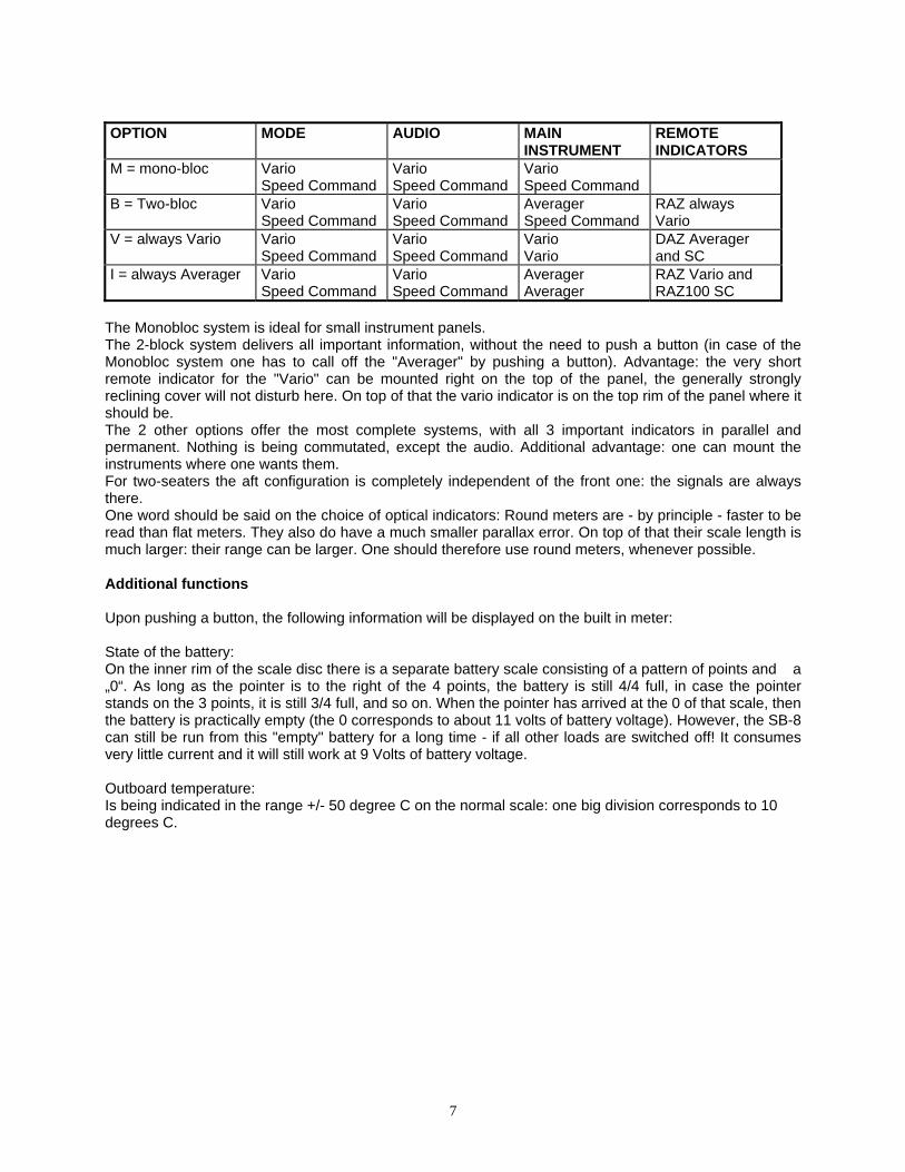
2.7. Indicators Depending on the configuration of remote indicators used, the built in indicator will automatically be switched to a different signal, this as a function of mode. To take care of the configuration of remote indicators, the instrument can be programmed internally. A maximum of 2 out of the 3 signals "Vario", "Integrator" = averager, or "speed command", can be indicated on the built in indicator (No sweat, ILEC will already have executed the programming for the configuration ordered). By principle, the 3 signals mentioned above are fed to the connector at the rear of the instrument, this without them being influenced by the mode in which the instrument actually is. If one connects remote indicators to the rear connector, the corresponding signals will be indicated p e r m a n e n t l y. This feature is particularly interesting for two-seaters! There are 4 options for the basic instrument, which determine the configurations possible, they are assembled in the table below. (Instructions for connecting the remote indicators are to be found in chapter 3.4., for programming in chapter 5.6.
7
OPTION MODE AUDIO MAIN
INSTRUMENT REMOTE INDICATORS
M = mono-bloc Vario Speed Command
Vario Speed Command
Vario Speed Command
B = Two-bloc Vario Speed Command
Vario Speed Command
Averager Speed Command
RAZ always Vario
V = always Vario Vario Speed Command
Vario Speed Command
Vario Vario
DAZ Averager and SC
I = always Averager Vario Speed Command
Vario Speed Command
Averager Averager
RAZ Vario and RAZ100 SC
The Monobloc system is ideal for small instrument panels. The 2-block system delivers all important information, without the need to push a button (in case of the Monobloc system one has to call off the "Averager" by pushing a button). Advantage: the very short remote indicator for the "Vario" can be mounted right on the top of the panel, the generally strongly reclining cover will not disturb here. On top of that the vario indicator is on the top rim of the panel where it should be. The 2 other options offer the most complete systems, with all 3 important indicators in parallel and permanent. Nothing is being commutated, except the audio. Additional advantage: one can mount the instruments where one wants them. For two-seaters the aft configuration is completely independent of the front one: the signals are always there. One word should be said on the choice of optical indicators: Round meters are - by principle - faster to be read than flat meters. They also do have a much smaller parallax error. On top of that their scale length is much larger: their range can be larger. One should therefore use round meters, whenever possible. Additional functions Upon pushing a button, the following information will be displayed on the built in meter: State of the battery: On the inner rim of the scale disc there is a separate battery scale consisting of a pattern of points and a „0“. As long as the pointer is to the right of the 4 points, the battery is still 4/4 full, in case the pointer stands on the 3 points, it is still 3/4 full, and so on. When the pointer has arrived at the 0 of that scale, then the battery is practically empty (the 0 corresponds to about 11 volts of battery voltage). However, the SB-8 can still be run from this "empty" battery for a long time - if all other loads are switched off! It consumes very little current and it will still work at 9 Volts of battery voltage. Outboard temperature: Is being indicated in the range +/- 50 degree C on the normal scale: one big division corresponds to 10 degrees C.

8
2.8. Distance- and Final glide computer Nearly all signals which the Distance- and Final-glide-computer (ASR) needs, are drawn from the SB-8. This means, that one will set the necessary parameters (wing loading, McCready-value, polar, mode) on the SB-8, to forget them then. In particular the mode does not have to be switched separately. Exceptions to the rule: Wind and distance, they are set on the ASR itself. For this to be possible, the ASR has to be connected to the SB-8 via the cable provided by ILEC.
2.9. Precision For general specifications see the prospectus. Altitude error: The Calibration factor (not the zero!) of the variometer depends on air density and therefore on altitude. (Other systems are also dependant on altitude, only in a different way, as long as they are not actively corrected for the effect, correction, which is generally only done on expensive instruments). When measuring vertical speed with the SB8 (vario), the indication decreases at a rate of 5 % per 1000 meters increase in altitude (= 5 % per 3 000 ft), measured against the value, which relates to IAS. This value, the only correct one, takes into account the increase in TAS at constant IAS with increasing altitude, it is the only correct one to be used for computing speed command. A moving vane variometer, by principle indicating t r u e v e r t i c a l speed - as one would measure it with stop watch and altimeter -, will indicate 5 % too much, measured against the correct scale!) As the transducer for total pressure also shows a decrease in magnitude of output with increasing altitude, both errors cancel one another partially for computing optimum speed. The residual error depends on the aircraft’s polar, the McCready-value entered, and actual air speed. It is approximately - 5% per 1000 m altitude difference (-5 % per 3 000 ft), where the averager output of the SB-8 is taken as the basis for the McCready input. The amount of error in the speed command finally remains within +/- 4 % in the altitude band of 400 to 2 000 m (1 200 to 6000 ft) and with this smaller than the calibration error of most other instruments. On top of that it acts such that one will fly a bit slower than theoretically optimal if at an altitude of less than 1 200 m (3 600 ft), and a bit faster if above (maximum error: 4 % in the normal altitude band). Despite that, calibration altitude can be changed to 3 000 m (9 000 ft) by internal programming, for people who permanently fly at high altitudes. One can also set the McCready-value a bit lower, by about 0.1 m/s for every 1 000 m altitude (3 000 ft). One will fly pretty much correct then. Precision of the speed command computer The computer itself works at high precision (much more precisely than one can possibly fly) in the speed range from 70 to 220 km/h (39 to 122 kts): better than 2 %. It functions, however, up to 270 km/h (150 kts) to avoid large errors at extremely fast flight. The approximation of the plane's polar - on which computation at the end is based - by the parabola programmed, is better than +/- 5 cm/s (0.1 kts) in the most important range of 70 to 150 km/h (39 to 83 kts). It is better than +/- 10 cm/s (0.2 kts) beyond that up to 180 km/h (100 kts). On the other side there can easily be uncertainties of up to 50 cm/s (1 kts) in the polar due to bugs!
9
3. INSTALLATION
3.1. Unpacking, packaging Unpack instrument carefully and inspect it for possible external damage by transport. In case of damage keep packaging material to substantiate claim against the carrier and to return the instrument. When packaging the instrument, for any reason whatsoever, take care to close the rear pneumatic nipples to prevent contamination of the measuring system! Use large case and fill void with soft material (Styrofoam chips e.g.) for shock absorption.
3.2. Warranty Warranty of the manufacturer covers failures in material and manufacturing of the product for a period of 2 years after delivery. ILEC will replace or repair parts of the instrument that have failed in the warranty period, provided the instrument has been returned free of charge, and provided, it had been operated within the limits specified in this manual and in the prospectus. ILEC cannot be held responsible for consequential damages caused by a failure of the instrument, or any other cause, which might be connected with the instrument. In particular, no warranty can be claimed, where any liquid (water e.g.) or foreign particles have been allowed to penetrate into the pneumatic ports. In case of trouble, describe the problem as exactly as possible, to avoid unnecessary enquiries (statements such as "vario out of order", or similar, will not always do the job). Please give a telephone number, under which a person competent technically can be reached.
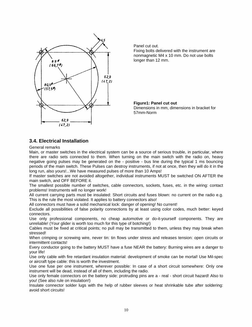
3.3. Mechanical Installation When choosing the place where the instrument is to be installed, the following points should be considered: As the vario is read rather frequently, the vario INDICATOR should be placed at the upper rim of the instrument panel (main instrument or remote indicator, depending on configuration of instrument). If a compass is being installed in the instrument panel, all other nonmagnetic instruments should be grouped around it (altimeter, air speed indicator, moving vane variometer); all electrical instruments at a distance of some 10 to 15 cm. The analog applies to compasses mounted on the cover of the panel: the loudspeaker at the rear end of the instrument may disturb this compass. Remedy: mount SB-8 further down, or have loudspeaker taken out by the manufacturer and use remote speaker. When respecting these hints, the compass will not be disturbed by more than +/- 15 degrees and can be compensated to good precision, say to +/- 5 degrees easily. Instruments that are read infrequently, radio sets e.g. should be placed low on the panel (see also chapter 2.7.). During transport, take off, and landing, the glider will be submitted to rather severe shocks. These should be kept away from ALL instruments. Contrary to a widespread opinion, the best suspension is none at all: Best is the one that will link all instruments to the primary structure of the fuselage in the MOST RIGID way (the fuselage itself is very stiff, and has a large mass). For this reason panels should be designed for maximum rigidity and fixed to the fuselage rigidly. Nothing is more damaging than the shocks handed out as a too softly suspended panel hits the structure limiting its free travel. Temperature transducer The most favorable place for the temperature transducer is the ventilation duct near the air inlet, as there it is well stirred by the air, protected from the sunrays, and, on top of that protected against accidental damage. For mounting, drill a hole 5,5 mm diameter, push the transducer head through it, and fix it with some adhesive tape.
10
Panel cut out. Fixing bolts delivered with the instrument are nonmagnetic M4 x 10 mm. Do not use bolts longer than 12 mm. Figure1: Panel cut out Dimensions in mm, dimensions in bracket for 57mm-Norm
3.4. Electrical Installation General remarks Main, or master switches in the electrical system can be a source of serious trouble, in particular, where there are radio sets connected to them. When turning on the main switch with the radio on, heavy negative going pulses may be generated on the - positive - bus line during the typical 1 ms bouncing periods of the main switch. These Pulses can destroy instruments, if not at once, then they will do it in the long run, also yours!...We have measured pulses of more than 10 Amps! If master switches are not avoided altogether, individual instruments MUST be switched ON AFTER the main switch, and OFF BEFORE it. The smallest possible number of switches, cable connectors, sockets, fuses, etc. in the wiring: contact problems! Instruments will no longer work! All current carrying parts must be insulated: Short circuits and fuses blown: no current on the radio e.g. This is the rule the most violated. It applies to battery connectors also! All connectors must have a solid mechanical lock: danger of opening! No current! Exclude all possibilities of false polarity connections by at least using color codes, much better: keyed connectors. Use only professional components, no cheap automotive or do-it-yourself components. They are unreliable! (Your glider is worth too much for this type of botching!) Cables must be fixed at critical points; no pull may be transmitted to them, unless they may break when stressed! When crimping or screwing wire, never tin: tin flows under stress and releases tension: open circuits or intermittent contacts! Every conductor going to the battery MUST have a fuse NEAR the battery: Burning wires are a danger to your life! Use only cable with fire retardant insulation material: development of smoke can be mortal! Use Mil-spec or aircraft type cable: this is worth the investment. Use one fuse per one instrument, wherever possible: In case of a short circuit somewhere: Only one instrument will be dead, instead of all of them, including the radio. Use only female connectors on the battery side: protruding pins are a - real - short circuit hazard! Also to you! (See also rule on insulation!) Insulate connector solder lugs with the help of rubber sleeves or heat shrinkable tube after soldering: avoid short circuits!
11
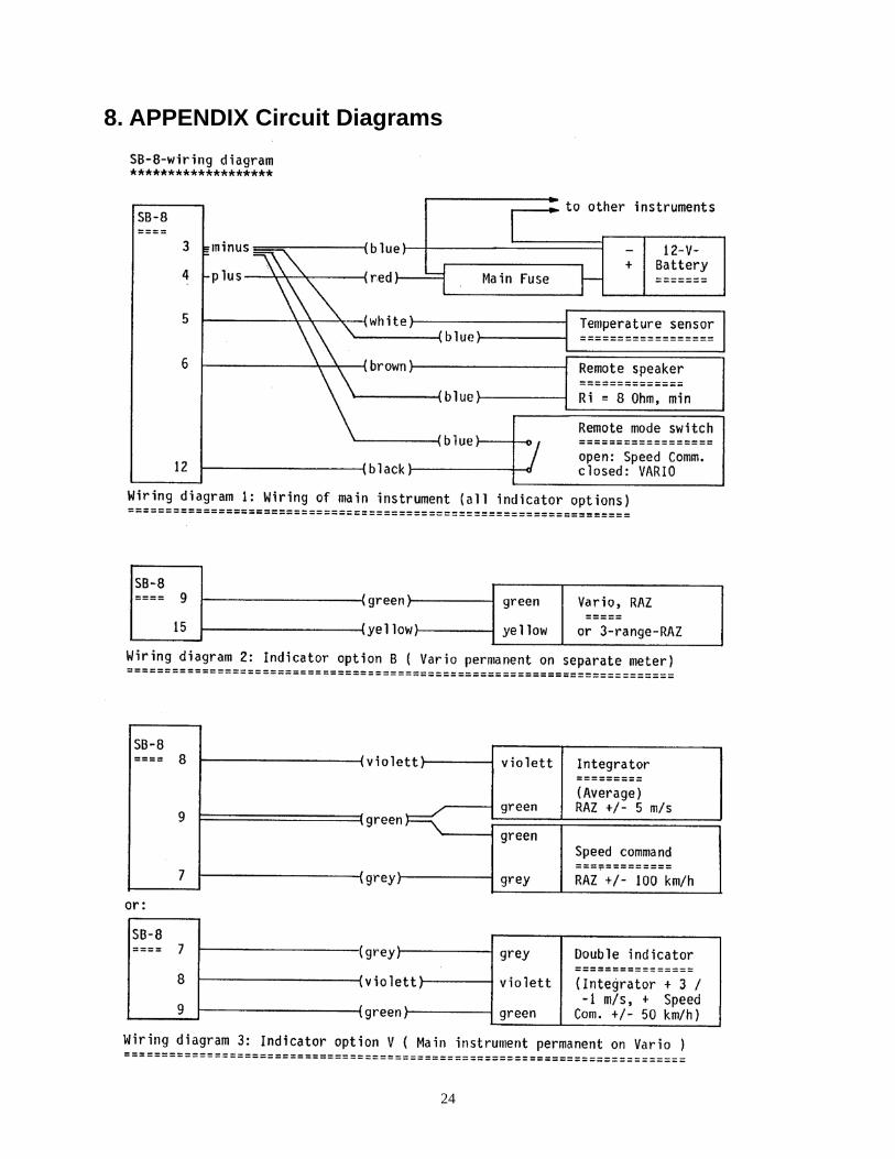
Use a soldering pin compatible with the size of contacts to be made; a 1 Kg/100 Watt iron is definitely not the right equipment here. Better still: look for an electronic technician to do the job for you! He is there everywhere! To reduce electromagnetic interference to ALL instruments, in particular the one caused by a VHF transmitter: (this is a general nuisance) All wires must be as short as possible, also those not carrying RF. Use only good antennas, poor or poorly adapted antennas return a large fraction of the RF energy being sent to them on the exterior of the antenna cable: The whole aircraft will be polluted by this stray RF radiation! Keep the antenna cable away from any other wire (a foot is not too large!) ALL grounds must be returned to one single point (every equipment has a supply and a return, even if the latter is by its case). Cases of all electrically operated instruments also are to be connected to this central "GROUND". This central ground point itself must be bonded - via a very short wire - to the structural metallic ground of the aircraft, (the steering system e.g.) this is not just for the above reasons, but also to protect the pilot in case of a lightning strike. A very good central grounding point is a metallic instrument panel. This is the reason why they are to be preferred over the more modern plastic insulating ones. The negative terminal of the battery must be linked to the central ground point by a very short heavy wire. Cable harness The SB-8 is being delivered with a standard cable harness comprising: connector, battery wires, temperature transducer, remote control cable, cable 60 cm long for vario separate indicator. In case an ASR is ordered at the same time with the SB-8, or in case this is desired, this harness is being complemented by a cable and its connector for the ASR. In case an ASR is being attached to the SB-8 without the harness having been prepared in advance, a new cabling set will be delivered with the ASR. The old temperature transducer must be connected to this new harness, as the instrument has been calibrated with this transducer (cut through flat double cable white/blue of the old harness, solder transducer to the corresponding end of the new harness, insulate). Schematic 1 shows the wiring of the main instrument. Remote Speaker and Remote Control according to need. For Monobloc configuration no other wiring is necessary. Insulate all wire ends not used. Schematics 2 to 6 show other configurations of indicators and corresponding wirings for single- and two-seaters. For two-seaters the instruments for the aft panel are being connected completely independent of the ones of the front. NOTE: electronic technicians must do the cabling: it determines to a large part reliability of the complete system. Special Remarks: Wires for the separate (remote) indicators are color coded as are the connectors. As far as possible, all inputs and outputs are protected against false connections. However, it is not possible to foresee all false connections one can possibly make. Therefore total protection is not feasible. The nearly only dangerous connections are those where the negative terminal of the battery is linked to a signal out-, or input, and the battery's positive terminal to the Minus input of the instrument. (This happened!). Inversion of the battery's polarity on the two input cables of the instrument, otherwise, is without consequences. Therefore: Never hook up the battery to anything else than its proper cable and input terminals. ILEC will give no warranty in case of false electrical connections.
12
Remote Control There is not yet a truly satisfactory solution for automatic control of the mode (thermal/cruise) of a vario/speed command system. Not to talk of a distance counter. No automatic system whatsoever will have eyes, or intentions, as has the pilot. In the case of gliders with flaps one can control the instrument via the position of the flap lever. The manufacturer of the plane must install the controlling switch, mostly a magnetically operated reed switch. He has the necessary material, and more important: the specific expertise. For gliders with fixed airfoils the best solution (the best solution for all planes indeed) is, to mount a small switch near the usual rest position of the left hand, or on the stick. In this way it is very easy - and carried out more or less automatic by the pilot - to switch to the right mode, and on top of that, it is done at the right moment, just as the pilot knows and wants it. The automatic device will do the job also, however poorly usually. Very quickly the correct switching becomes a routine, not demanding any attention.
3.5. Pneumatic connections Input pressures The instrument must be connected to Total Pressure (measurement pressure of the airspeed indicator) and to a Te-probe via the 2 nipples on the rear. As the quality of the variometer's response depends entirely on the quality of the TE-pressure, a good TE-probe should be used. It should be sufficiently insensitive to slip and changes in angle of attack. The best tube is worth nothing, if mounted in the wrong position. The best position is still the one high up on the tail fin. For details see brochure "Total energy compensation in practice" which ILEC will send you against a protective fee. It contains, in short form, the results of several years of research into the subject. Protection against water and dust ANY pneumatic instrument can be damaged by dust or water ingested. Therefore a water separator must be inserted into any line leading outboard. As, on top of that, most tubing on gliders is being, or has been, heavily contaminated by dust from sanding, small gasoline filters, available in car shops, must be inserted into each tube next to the instrument. They should remain there forever, also when returning an instrument. Certainly they should never be reversed: This would be the best way to drive the dust collected so far right into the instrument. These filters are excellent water separators at the same time! It must be repeated here, that ILEC will refuse any warranty where instruments have suffered from water or dirt ingestion. Connecting tubing Nipples are for flexible tubes with inner diameter of 4 to 5 mm. In case a tube sits too tight: do not pull with brute force, cut it open carefully - without damaging the nipple! Use an adaptor where tubing is too wide or too narrow, collets are normally unreliable. Best tubing is rubber tubing with textile shroud (= gasoline tube): it remains elastic at low temperatures, never becomes soft, maintains its seal even after years, is easily pulled off, does not shut off in tight bends, and holds water ingested in a film without forming drops that clog the line. Have tube end run straight into the nipple, without bend. Transparent PVC tubes 5 x 1.5 mm are acceptable. However, they become hard when cold, and over the years. They must be replaced every 2 years to avoid potential leaks. Leaks are usually fatal for a variometer indication. Leak tightness The line from the measuring head of the TE-tube up to the variometer must be tight. The following is a rapid test; it should be carried out at least at the start of the season.
13
1. Seal the total pressure port on the variometer (piece of tubing closed off at one end with a piece of 6mm round brass bar, no screw! Or melted tight by soldering iron). 2. Press flexible tube next to vario. 3. Seal off TE-probe (finger or adhesive tape). 4. Release tube: vario produces a pulse in positive direction. 5. Wait 10 seconds. 6. Open TE-probe: vario produces a pulse in negative direction of about the same magnitude as above. If not, the system is not tight. Mutual interference between Variometers Where an SB-8 is run alone at a TE-tube, there is normally no problem, be it, and the line is clogged. Where a variometer with a big flask (big means here some liter, to be found with certain moving vane Varios or gust filters), is hooked up to the same tube: caution! The response of the SB-8 may be distorted by the large airflow in the system in case of sink or climb. Here, a test flight with all other instruments disconnected should be done for comparison, under all circumstances. (Although we have not seen many problems there!) Never should there be any capillaries or so called gust filters in the conduit between TE-tube and the SB-8, although this may be required on some Variometers, to make them more readable (by making them slower). At best they would only cause a delay in the response of the SB-8. Contrary to the widely distributed opinion, errors of a poor TE-compensation cannot be cured this way. (In doubt consult "TE -compensation in practice")
4. MAINTENANCE
4.1. General indications The SB-8 normally does not need any maintenance, nevertheless some hints to ensure reliable operation and long life: Most cases of malfunctioning (including those where we repair perfectly working SB-8s) are due to leaks! Next in the row of causes are problems with electrical contacts (see also under "Electrical Installation"). Too much heat is of no good to ANY instrument. The glider should not be abandoned carelessly in the naked sun without the cockpit being covered somehow. Temperatures in an uncovered cockpit can easily reach 70 degrees C. There are at least some momentary measurement errors to be expected, if not worse. (We have seen SB-8s with holes burnt into them!) If no cover is available, then at least open the canopy for air to circulate rather than stagnate. All tubing must be checked from time to time - and at any rate at the start of the flying season - for leak tightness, good tension around connecting elements, sharp bends and squeezes. Tubes gone hard must be replaced! (This is particularly necessary in the case of soft PVC tubing!) Protect your instruments, and their tubing, against dust and dirt! Before doing any repair on your glider, disconnect all tubes and shut off their ends. Take all instruments away. Must be checked from time to time: Connectors, switches, fuse holders, for good contact, insulation; and all cables for chafing, kinks, jamming, in order to spot intermittent contacts before they arise. Use only new, flawless fuses. Never try to repair them! You may destroy an instrument right on the spot, or loose it later. An old, feeble battery, or a doubtful one must be replaced immediately, not later.... The battery test function of your SB-8 will help you there. Recharge the battery systematically after every flight. You will not do it otherwise, on an occasion! The instrument panel hitting some structure of your fuselage upon bouncing around during take off and landing because of too sloppy a suspension, must be put right immediately.
4.2. Verifications Mechanical Zero:
14
There should be no problem with mechanical zero of the indicator. However it should be checked, because this is so simple. (Just look at the pointer, when the instrument is off!) As a consequence of an extremely hard shock, during transport e.g. one of the 2 spiral springs of the meter movement may become trapped in its support; the needle then will be wrong by half a division of the scale typically, and will show much friction. Here the instrument must be returned to the manufacturer. A watchmaker can usually cure the problem. Electrical Zero: Shut off both of the pneumatic connections of the instrument, or leave the glider in a constant temperature environment for at least an hour (in the hangar e.g.). The instrument must be on for at least some 15 minutes. Vario: Switch to Vario mode. The needle of the vario indicator (built in or separate, does not matter) should now be within +/- 0.1 m/s of the mechanical zero. In case the offset is larger, adjust the vario zero (see chapter 5 for details). (After a very long rest period, several weeks or months e.g., larger errors may show up after switching on, they should disappear, however, gradually within a quarter of an hour or so. Speed Command: To check zero of the transducer for the dynamic pressure, PUSH the POLAR SELECTION SWITCH to the extreme right. In case the built in meter indicates more than, say the width of the needle, electrical zero must be readjusted (see 5.2.) Verification of measurement of speed: To be taken care of when testing for speed measurement: the pressure actually taken as a measure for speed is TWICE the dynamic pressure. This is so for very valid reasons. (Total pressure, or Pitot pressure - TE-pressure = 2 x dynamic pressure). On the ground, when the TE-tube does not produce its suction, the IAS used as a pressure gauge must indicate root 2 times the corresponding speed!
4.3. Cleaning the Instrument For cleaning the exterior, the meter screen e.g., one must never use a strong solvent like tetra, or nitrocellulose, because they will damage or even destroy the plastic parts. Well suited are: lighter gasoline, turpentine (often used as thinner), or watered alcohol with a maximum concentration of 40 %. The screen of the indicator is of polycarbonate and sensitive to static electricity. It should not be rubbed with a dry cloth. In case static charges trap the needle, humidify the screen and cleanse it with an antistatic product. This will last for a season!
5. ADJUSTMENTS AND PROGRAMMING
5.1. General Normally there is no need for any adjustment or programming, as the manufacturer does this, normally knowing the glider type for which the instrument is intended and the configuration of indicators desired. We intend this chapter for the case where the customer wants to change something. For all adjustments one of the 2 half shells of the case must be removed. To do this, first remove the 6 corresponding self-tapping countersunk screws and pull off the half shell up-, or downwards. Never take away both half shells at the same time, as the instrument's parts will no longer be held together. After finishing the job, mount the half shell in the reverse order again. ATTENTION! When remounting a half shell, first turn the self tapping screws backwards until they fall back into their old track, then turn forward. The threads in the plastic parts might get fouled otherwise! When mounting the lower shell, take care not to squeeze the silicon tube! Observe the most stringent measures of cleanliness. Even the smallest magnetic particles can disturb seriously the meter movement!
15
Always pull off the battery connector before working on the instrument. Do not touch sealed trim pots because calibration would be lost!
5.2. Zeroing of the Transducers Proceed as described under 4.2. Take away the upper half shell after having pulled the battery connector. Reconnect battery. For adjustment turn trim pots identified on the last page of this manual using a small screwdriver (max 3 mm wide) until zero is correct. (Switch to the 3-s response for the variosignal). Pull battery connector, close instrument again.
5.3. Calibration Altitude Normally the instrument is set to a calibration altitude of 1 200 m NN, which is correct for 99 instruments out of 100 (see chapter 2.8.). To change to 3 000 m hook the 2 wire springs of the programming switches on the rear circuit board (see photo on last page) into the corresponding small hook.
5.4. Audio Generator If not specified otherwise by the customer, the ILEC tone will be programmed. To change to the interrupted tone: (see photo on last page) change the right one of the 3 wire springs from the second small hook from the right to the most right one. If a double tone is wanted, unhook one of the 2 left springs; for a single tone, unhook both of them. For adjustment of the pitch (the frequency) of the base tone, or for adjustment of the frequency of modulation of this base tone, turn the corresponding trim pots. The dead band of the speed command tone is factory set to +/- 15 km/h, it becomes narrower by turning the trim pot to the right. Remark: One should test the effect of an adjustment on the audio generator. For this, open the upper half shell, then insert the rear connector (cable loom in the glider), and switch on. Make the vario play with the help of a piece of flexible tubing connected to the TE-nipple, shut off at the end, and listen to the sound. Switch to the other mode for speed command audio.
5.5. Programming the Polar If the polar programmed by the factory is to be changed, the lower half shell must be taken off. Set the 4 programming switches to the new values using a small screwdriver (see last page). The parameters for the usual types of gliders are available from the manufacturer or his representative and will be communicated on request. For non-standard cases there is a written procedure for computation of the parameters.
5.6. Indicator Options (Configurations) The configurations described in chapter 2.7. , are taken care of with the help of the programming switches on the 2nd printed circuit board. The table below shows how to do it: Option Upper spring Lower spring M = Monobloc Open Hooked upwards B = Two bloc (Vario at RAZ) Open Hooked downwards V = SB-8 indicates Vario Hooked Hooked upwards I = SB-8 indicates Averager Hooked Hooked downwards
16
6. REPAIR The instrument has been produced very carefully. To eliminate initial failures that arrive with all components, it has been burnt in for a long time before its delivery. Nevertheless there are failures, arriving statistically at a later date, failures which we cannot eliminate. In case you should have a problem, please check that everything has been done as specified in this manual. (In particular in the case of a new instrument! Should the instrument already have worked correctly for some time, then most probably a component failure is the culprit! At the beginning of the flying season, very often the batteries are at their end of life! Often leaks have developed over the cold season!) In the regrettable case of a necessary repair, please call us or our representative, or return the instrument immediately, not only when you just want to fly: As everybody wants the same, we will be overloaded with work. We try to fix a repair within one week. In case there is no trouble with transport, you will have the vario back for the following weekend, if you send us the instrument on Monday. Sometimes we prefer to run the instrument for some time to make sure everything is all right, but then we will tell you. In case you send the package from abroad, please make sure you declare a low enough value for the merchandise to pass through customs without any trouble (this will save work to us, and time to you!). You will get the corresponding green sticker to glue on the package and the advice from the local mail office. Please describe the malfunction, the instrument produces, as exactly as possible on a piece of paper and also state a telephone number for queries. You make it easier for us to find the cause, this way you speed up treatment of this regrettable matter. (For the rest proceed as said at the beginning of the chapter on Installation)

17
7. THE VARIOMETER SB-8 IN FLIGHT The following chapter has been written in order to help the user to draw a maximum of benefit from the information delivered by the instrument. It is always worth while to read it, as the matter treated here is rarely or not at all covered in the general literature on soaring.
7.1. The 1-second and the 3-second responses Figure 2 shows what happens upon flying through an idealized thermal, and the corresponding responses of the 2 different filter outputs, or otherwise, the indication of the vario needle when one or the other response has been selected. For the example a standard class glider with normal wing loading has been assumed. Airspeed is 90 km/h (50 kts), and constant. The thick square trace 1 shows the updraft as a function of time: in front of the jump, there is calm air, within it, the air rises at 2 m/s (4 knots) diameter be 100 m (100 yards). Before entering, the plane sinks steadily at 0.7 m/s (1.4 kts). Upon entering, it is accelerated upwards, (and very slightly forwards, but this assumes no reaction from the pilot) the pilot will feel this clearly on the seat of his pants. The transition to the new vertical speed is fast, the time constant being only 0.4 seconds. (Gust-?) Acceleration at the beginning is 0,5 g, the g-meter will jump from its steady state indication of 1 g to 1.5 g. (Upon leaving the same sequence will happen, however this time downwards.) Curve 3 describes the indication by the 1-second filter: after a short hesitation of about .2 s the needle swiftly swings upwards, after 2 seconds already 90 % of the change are reached, after 2.5 s 100 % of the real climb rate of the glider, now being 1.3 m/s (2.6 kts) upwards, are attained. The indicator needle remains there to the very end of the updraft, and returns to its original sink of .7 m/s (1.4 kts) as fast as it mounted upon leaving the thermal (gust?).
Figure 2: Passing through an updraft REMARK: For a first order filter to be as fast, its time constant would have to be 1 second. Such a filter would be useless in normal thermal conditions as one would not be able to read it because of its permanent random jitter induced by turbulence.

18
Curve 4 shows the behavior of the slow 3-s filter. This one corresponds to the response of a good moving vane variometer: The output creeps up slowly. For it to reach 90 % of the change in input, one would have to wait 7 seconds. At the end of our thermal it just arrived at 0.8 m/s (instead of 1.3!). Which response to use to search for thermals?? As the main problem here consists of discriminating between "gusts" and useful lift, a short consideration: diameter of the general useful thermal is about 150 m. This distance at a speed of 90 km/h (50 kts) will be covered in about 6 s, at 180 km/h (100 kts) in 3 seconds. With this in mind, one can say that it is worthwhile to take on a "thermal" when the climb lasts at least 3 to 5 seconds, (and when on top of that it has the strength looked for. Be it, one is convinced to have cut the lift just on its border. If now we look at figure 2, we can set up a simple rule for day to day use very quickly (it has proven its validity in practice): When the FAST vario climbs to the lift waited for, then COUNT TO 3. If the needle is still there, then take it on: this thermal is large enough to be centered in 9 out of 10 cases; if not, continue straight on!! In case the slow filter has been selected, one will have to not only observe the position of the pointer, but also its tendency: Does it STILL CLIMB (after 3 seconds), and does it at least indicate HALF of what is waited for, then take it!! In case it STANDS STILL or even FALLS, continue on your way. (One thing needs to be said: No vario of this world can predict, what the climb rate will be in the thermal just taken on. The good pilot will be able to do that, because he sees infinitely more than the vario. A vario will be able to tell only AFTER the circle has been flown, NOT BEFORE!!).
7.2. Turbulence and gusts Everything that is shorter than a useful lift is only a disturbance. This is particularly so for horizontal gusts, which are so widely distributed, but rarely recognized as such. Therefore it would be nice, if a vario would simply suppress those short "gusts". (Suppression of horizontal gusts by TE-vario is - by principle - impossible. At the end: because it is its measurement principle to eliminate "stick thermals". As a way out, one can look at flight speed as well as vertical speed individually, and then draw one's conclusions: one has to - at least for short time intervals - disregard compensation of the stick thermals. This means taking into account a simple altitude variometer (non compensated vario), look at the TE-vario later only, and draw one's conclusions from a comparison of the 2 signals. The good pilot does something similar all the time, and even more. The whole procedure happens in his brain. He uses all his senses. Therefore his high concentration) For the time being, we have to be happy with filtering out "gusts" as efficiently as possible, without loosing too much in speed of reaction. This is already difficult enough. To show the influence of a gust on the indication of a TE-vario, let us assume the following case: A standard class glider flies at 150 km/H (83 kts). On the one hand it enters a thermal with a vertical air speed of 2 m/s (4 knots), on the other hand a zone with wind shear or - what is the same - a whirl with horizontal axis such that the plane's airspeed increases suddenly by 2 m/s (4 kts). What happens in those two cases? Well, figure 2 shows it for the case of the thermal. There is some difference to fig.2, though: the initial sink rate is 1.8 m/s (3.6 kts) rather than .7 m/s (1.4 kts). The initial thrust of vertical acceleration is stronger, due to the higher airspeed. The plane is accelerated upwards from -1.8 m/s to + 0.2 m/s, 150/90 times as strong as in fig.2. The g-meter would bounce from 1.0 g, its steady state value to 1.8 g and back again to 1 g with a time constant of only 0.25 s. The response of the variometer is exactly as in Fig.2, the curves only a bit lower.

19
Figure 3: Entry into a horizontal Gust Fig.3 shows the case of the horizontal gust: The airspeed indicator jumps from 150 to 157 km/h (from 83 to 87 kts), damped by its inertia (this makes the bounce practically invisible). Contrary to what we have seen in the case of the thermal, the plane is being accelerated upwards only a little bit, just 0.1g. The trajectory of the glider that follows depends mainly on the pilot's reaction: He can continue at the increased airspeed, or swap the kinetic energy he has gained for a bit more altitude. In the example this would be 8.7 m !! and then continue at his original airspeed. His maneuver however has little influence on the TE-vario: at entry into the whirl, the TE-vario "sees" a jump in dynamic pressure corresponding to the altitude jump of 8.7 m. It will interpret this pressure jump correctly as a gain in energy and produce a positive pulse. This pulse will be proportional to the potential gain in altitude. Thereafter it is irrelevant to the TE-vario whether the potential gain in altitude is realized or not, as there would be no change in total energy involved in the maneuver, only an exchange between kinetic and potential energy. The needle's excursion is larger here than in the case of the thermal. The needle’s movement will die out again, how fast; this depends on the kind of filter used (in the case of some Varios one does not need any filters, because the transducer itself is slow and therefore imposes its - usually very slow - response on the whole system). The slow 3-s response can make the pilot think there is some lift, which is no longer there, really. It must not be forgotten, that in practice, turbulences, as well as thermals, are rarely as sharp edged as drawn here, for clarity reasons. The leading edge of the indication will therefore mostly be "rounder" than shown in figures 2 and 3. 1. When the vario climbs fast, without being accompanied by a strong acceleration upwards, then most frequently we have to deal with a horizontal gust. One can "pull out" the excess speed, however one has to reckon with being forced to "push over" a rather short time afterwards again, because a negative jump follows. 2. When the vario departs upwards after an upward thrust of vertical acceleration, mostly there will be lift. 3. In weak thermal conditions the vario will usually climb slowly. In principle now a large field of lift can announce itself, however, it does not have to be so. Mostly one will not feel single acceleration signals, and one will have to entirely rely on indication of the vario and one's "feeling". Newer measurements indicate that the leading edges of thermals are mostly very poorly defined, reason why there are no clear accelerations.
20
In case 3 it is advisable to reduce speed and follow the vario very carefully.
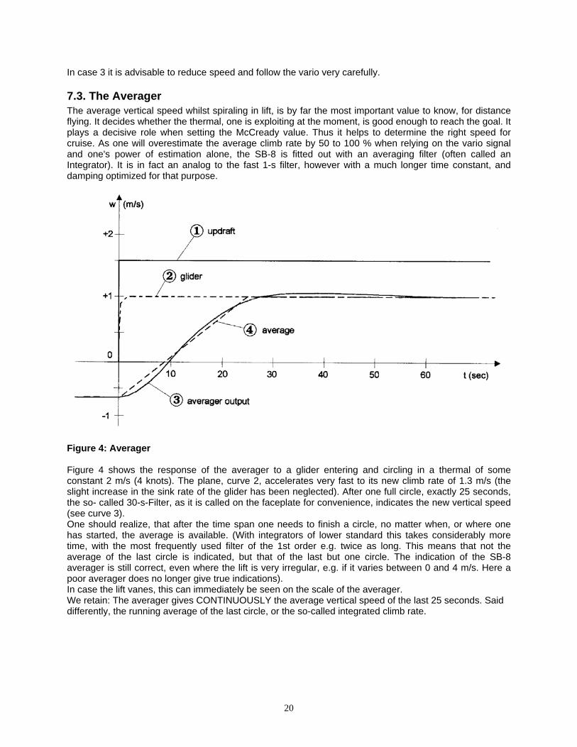
7.3. The Averager The average vertical speed whilst spiraling in lift, is by far the most important value to know, for distance flying. It decides whether the thermal, one is exploiting at the moment, is good enough to reach the goal. It plays a decisive role when setting the McCready value. Thus it helps to determine the right speed for cruise. As one will overestimate the average climb rate by 50 to 100 % when relying on the vario signal and one's power of estimation alone, the SB-8 is fitted out with an averaging filter (often called an Integrator). It is in fact an analog to the fast 1-s filter, however with a much longer time constant, and damping optimized for that purpose.
Figure 4: Averager Figure 4 shows the response of the averager to a glider entering and circling in a thermal of some constant 2 m/s (4 knots). The plane, curve 2, accelerates very fast to its new climb rate of 1.3 m/s (the slight increase in the sink rate of the glider has been neglected). After one full circle, exactly 25 seconds, the so- called 30-s-Filter, as it is called on the faceplate for convenience, indicates the new vertical speed (see curve 3). One should realize, that after the time span one needs to finish a circle, no matter when, or where one has started, the average is available. (With integrators of lower standard this takes considerably more time, with the most frequently used filter of the 1st order e.g. twice as long. This means that not the average of the last circle is indicated, but that of the last but one circle. The indication of the SB-8 averager is still correct, even where the lift is very irregular, e.g. if it varies between 0 and 4 m/s. Here a poor averager does no longer give true indications). In case the lift vanes, this can immediately be seen on the scale of the averager. We retain: The averager gives CONTINUOUSLY the average vertical speed of the last 25 seconds. Said differently, the running average of the last circle, or the so-called integrated climb rate.

21
7.4. Flying with the Speed Command We will not treat general tactics in transition or dolphin flying here, one will find this in the special literature, see "Reichmann" e.g. We only give some hints to pilot the glider and to interpret the speed command signal. One will set wing loading according to the overall mass of the glider (empty weight of the glider + weight of the pilot + parachute + water ballast) divided by wing area. (Computed in kg/sqm or lb/sqft, depending on the scale of the SB-8). Accuracy here is of no concern. (Most 15 m gliders have about 10 sqm of wing area, in this case take 1/10th of the all up weight, when using the metric McCready scale). Depending on the number of bugs on the wing l e a d i n g e d g e one chooses either the N-, or the X-polar, the latter at about 1 bug every 5 to 10 cm (2 to 4 inches), or worse. The by far most important parameter is the McCready-value that has to be set according to the tactical situation. Basis for this setting is always the average of the e x p e c t e d climb (it is to be estimated on the basis of the value one has had earlier during the flight, and the weather conditions ahead, conditions which really only the pilot can know). Particular tactical situations require particular values: flying over an obstacle at a distance e.g. Even large deviations from the optimal value lead to relatively minor losses in average cross-country speed. Therefore, it appears wise to use reduced settings, and to avoid too great a risk. It is not even unnecessary, but harms the physical condition of any pilot, if one blindly follows the needle, and practices violent dolphin flying. Adjust speed only, therefore, if a speed error stays there for some time, or if it menaces to do so! Follow the signal attentively, and react only, if it is worthwhile! (in case one begins to fly through an area of heavy sink e.g.) NOTA BENE: Any correction of speed to be carried out, must remain a tactical decision by the pilot, adapted to a particular situation. There can be no automatic reaction! How to change Airspeed following the speed command? There are 2 different methods, to adjust speed - in a controlled fashion - unfortunately they are not known. (As it does not work otherwise, as proven a thousand times by o l d speed command systems, the SB-8 has a computer which calculates the difference between the speed actually held, and the optimal speed of the moment. (Indication is calibrated in km/h or kts). Adjustment is done in the following way: 1. As a habit, the nose of the glider is pushed down or pulled up by the same angle, say 15 degrees e.g. with reference to the normal attitude, each time, speed is to be changed. One maintains this new attitude just so long as for the speed to change by the amount wanted. After a short while, this will become automatic, meaning, the time span will be chosen such as to be the correct one by the pilot, right from the start of the maneuver. He does not have to look to the IAS any more to see whether he has reached the new speed or not. The whole thing works so well, because with this method, the time span during which the nose of the aircraft remains inclined, is proportional to the speed change made: one doses the time span and by doing this, the change in airspeed intended. 2. Pilots who already master the above method can now hold constant the time span, during which there is to be acceleration or deceleration. Now, they must dose the inclination change. This method adapts itself to the meteorological conditions: One flies softer in weak conditions, tougher in strong conditions. In most cases one arrives, after some experience with the SB-8, automatically at combining the 2 methods. What counts: To change attitude by a certain angle for a certain time span, and this knowingly in advance. It is wrong to wait for the IAS to show the wanted speed, or even worse, for the speed command to show zero. This way, one will mostly dolphin about the correct value.

22
7.6. Looking for thermals with the speed command Here 2 cases are to be distinguished: 1. Upon a sudden change in the indication of the speed command, one best proceeds according to what has been said in 7.1. by using the speed command as a vario. However be careful, zero position is set off, one should not change speed too much, as speed has a strong influence on the zero reading of the speed command. The time response of the speed command is the 3s one. (In the case treated here, a permanent vario indicator is very useful). In case of a justified suspicion, switch to vario and continue your search with that. 2. Upon a slow increase of the speed command indication, one will automatically be guided towards a slower speed. In case the speed command indication has arrived at the speed of minimum sink and the indicator needle still is on zero or higher, one has arrived in lift, being m o m e n t a r i l y at least as strong as the McCready value set. Here, at the latest one's attention should be aroused. (The experienced pilot will already have noticed at the seat of his pants that something has happened, and he will have reacted accordingly).
7.7. Influence of normal Acceleration on the Indication of a TE-vario When pulling up, in particular at low speeds, drastic increases in the proper sink rate of a glider may arrive, as a result of its increased load factor. These additional energy losses naturally are indicated by a good TE-vario. They are not to be taken as errors of compensation. Whilst pushing over at low speed, on the other hand, the proper sink rate will be diminished; it can go nearly up to zero. (Influence of the air column in the longitudinal direction can reinforce this effect, and drive the vario needle even to above zero (in still air!) (The effect of the air column is a real measurement error; influence of the normal acceleration, however, is not an error, the losses indicated are real!!).

23
24
8. APPENDIX Circuit Diagrams

25

26