1 technical information - rulmecacorp.com · 1.8.3 belt conveyor covers ... on project design for...
TRANSCRIPT

9
1 Technical Information project and design criteria for belt conveyors

10
TechnicalInformationproject and design criteriafor belt conveyors
1
®
Summary 1 Technical information page 9
1.1 Introduction ................................................................ 11
1.2 Technical symbols ..................................................... 12
1.3 Technical characteristics of belt conveyors ............. 14
1.4 Component elements of a belt conveyor .................. 16
1.5 Project criteria ........................................................... 181.5.1 Conveyed Material ....................................................... 181.5.2 Belt speed ................................................................... 231.5.3 Belt width ................................................................... 241.5.4 Type of troughing set, pitch and transition distance ...... 321.5.5 Tangential force, absorbed power, passive .................. 36
resistance, belt weight, tensions and checks1.5.6 Belt conveyor drive types and drum dimensions .......... 44
1.6 Rollers, function and critical data ............................ 481.6.1 Choice of roller diameter in relation to speed ................ 491.6.2 Choice of type in relation to load ................................. 50
1.7 Loading of belt and impact rollers .............................. 531.7.1 Calculation of associated forces on impact rollers ........ 54
1.8 Accessories ............................................................... 581.8.1 Belt cleaners ............................................................... 581.8.2 Belt inversion ............................................................... 591.8.3 Belt conveyor covers ................................................... 59
1.9 Project examples ...................................................... 60
11
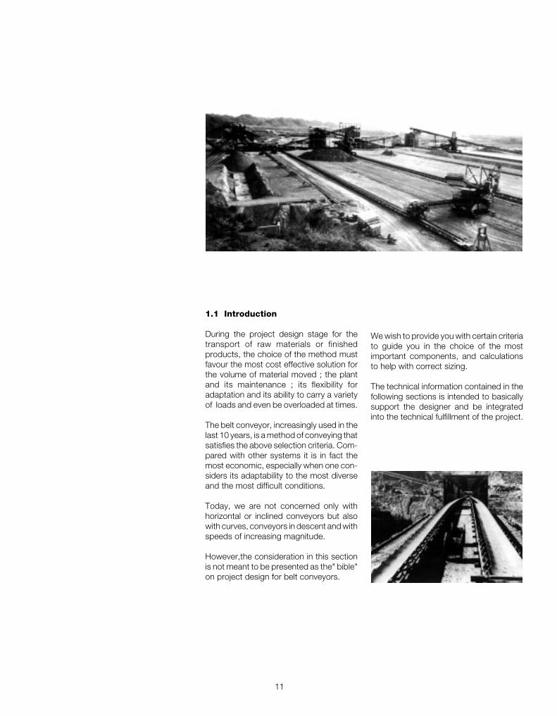
1.1 Introduction
During the project design stage for thetransport of raw materials or finishedproducts, the choice of the method mustfavour the most cost effective solution forthe volume of material moved ; the plantand its maintenance ; its flexibility foradaptation and its ability to carry a varietyof loads and even be overloaded at times.
The belt conveyor, increasingly used in thelast 10 years, is a method of conveying thatsatisfies the above selection criteria. Com-pared with other systems it is in fact themost economic, especially when one con-siders its adaptability to the most diverseand the most difficult conditions.
Today, we are not concerned only withhorizontal or inclined conveyors but alsowith curves, conveyors in descent and withspeeds of increasing magnitude.
However,the consideration in this sectionis not meant to be presented as the" bible"on project design for belt conveyors.
We wish to provide you with certain criteriato guide you in the choice of the mostimportant components, and calculationsto help with correct sizing.
The technical information contained in thefollowing sections is intended to basicallysupport the designer and be integratedinto the technical fulfillment of the project.
12
TechnicalInformationproject and design criteriafor belt conveyors
1
®
1.2 Technical Symbols
a pitch of troughing sets mA length of roller spindle mmag distance between the pulley flange and support mai pitch of impact sets mao pitch of carrying sets mat pitch of transition sets mau pitch of return sets mB length of roller shell mmC distance between roller supports mmCa static load on the carrying set daNca load on central roller of the carrying set daNCa1 dynamic load on the carrying set daNcd dynamic load on the bearing daNCf constant of elasticity of the frame/impact roller Kg/mch flats of roller shaft mmCo static load on bearing daNCp resulting load of associated forces on motorised drum shaft daNCpr resulting load of associated forces on idler drum shaft daNCq coefficient of fixed resistance __
Cr static load on the return set daNcr load on the roller of return set daNCr1 dynamic load on the return set daNCt coefficient of passive resistance given by temperature __
Cw wrap factor __
d diameter of spindle/shaft mmD diameter of roller/pulley mmE modules of elasticity of steel daN/mm2
e logarithmic natural base 2,718f coefficient of internal friction of material and of rotating parts __
fa coefficient of friction between the belt and drum given an angleof wrap __
fr deflection of belt between two consecutive troughing sets mft deflection of a symmetrical shaft mmFa tangential force to move the belt in the direction of movement daNFd factor of impact __
Fm environmental factor __
Fp contribution factor __
Fpr contribution factor on the central roller of a troughing set __
Fr tangential force to move the belt in the return direction daNFs service factor __
Fu total tangential force daNFv speed factor __
G distance between support brackets mmGm weight of lump of material KgH height change of belt mHc corrected height of fall mHf height of fall of material belt-screen mHt height change between motorised drum and counterweight mHv height of fall of material screen - receiving belt mIC distance from centre of motorised drum to the centre of
the counterweight connection mIM load volume m3/hIV belt load (material flow) t/h

13
IVM load volume corrected to 1 m/s in relation to the inclinationand irregularity of the feed m3/h
IVT load volume theoretic to 1 m/s m3/hJ moment of inertia of section of material mm4
K inclination factor __
K1 correction factor __
σamm admissible stress daN/mm2
L load centres mLb dimensions of material lump mLt transition distance mMf bending moment daNmMif ideal bending moment daNmMt torsion moment daNmN belt width mmn revolutions per minute rpmP absorbed power kWpd dynamic falling force Kgpi impact force of falling material Kgpic force impact on central roller KgPpri weight of lower rotating parts KgPprs weight of upper rotating parts Kgqb weight of belt per linear metre Kg/mqbn weight of belt density Kg/m2
qG weight of material per linear metre Kg/mqRO weight of the upper rotating parts referred to the troughing set pitch Kg/mqRU weight of the lower rotating parts referred to the troughing set pitch Kg/mqs specific weight t/m3
qT weight of drum daNRL length of motorised drum face mmS section of belt material m2
T0 minimum tension at end of load zone daNT1 tension on input side daNT2 tension on output side daNT3 tension on idler drum daNTg tension on belt at the point of counterweight connection daNTmax tension at point of highest belt stress daNTumax unitary maximum tension of belt daN/mmTx tension of the belt at a considered point daNTy tension of the belt at a considered point daNv belt speed m/sV maximum rise of edge of belt mmW module of resistance mm3
α angle of wrap of belt on pulley degreeeαt inclination of rotating symmetrical shaft radβ angle of overload degreeeγ angle of screen inclination degreeeδ inclination of conveyor degreeeλ inclination of side roller of troughing set degreeeλ1 inclination of intermediate side roller degreeeλ2 inclination of external side roller degreeeη efficiency __
y angle deflection of bearing degreeeThe symbol for kilogram (kg) is intendedas a unit of force.

14
TechnicalInformationproject and design criteriafor belt conveyors
1
®
Based on the load large belt conveyors areable to show cost add savings of upto 40-60 % with respect to truck or lorrytransport.
The electrical and mechanical componentsof the conveyor such as rollers, drumsbearings, motors etc.... are producedaccording to the highest standards. Thequality level reached by majormanufacturers guarantees function andlong life.
The principal components of the conveyor,rollers and belt, need very little maintenanceproviding the design and the installationhas been correctly performed. Theelastomer belt needs only occasional orsuperficial repair and as the rollers aresealed for life they need no lubrication. Thehigh quality and advanced technology ofRulmeca may reduce even further, orsubstitute, the need for ordinarymaintenance.Drum lagging has a life of at least twoyears.The utilisation of adequate accessories toclean the belt at the feed and dischargepoints yields corresponding improvementsto increase the life of the installation withminor maintenance.
1.3 Technical characteristics of beltconveyors
The function of a belt conveyor is tocontinuously transport bulk materials of amixed or homogeneous sort, a variabledistance of some metres to tens ofkilometres. One of the principal componentsof the conveyor is the elastomer belt whichhas a double function :- to contain the conveyed material- to transmit the force necessary to movethe load.
The belt conveyor is designed to transportmaterial in a continuous movement on theupper part of the belt.
The belt surfaces, upper on the carryingstrand and lower on the return strand toucha series of rollers which are mounted fromthe conveyor structure itself in a groupknown as a troughing set. At either end ofthe conveyor the belt wraps around a pulley,one of which is coupled to a drive unit totransmit the motion.
The most competitive of other transportsystems is certainly that of using lorries,With respect to the latter, the belt conveyorpresents the following advantages :- reduction in numbers of personnel- reduction in energy consumption- long periods between maintenance- independence of the system to its surrounds- reduced business costs
Loading hopper
Return idler sets
Unloading hopper
Drive pulleyReturn pulley
Carryng troughing setsImpact troughing sets
Belt conveyor
Fig.1 - Basic drawing of a belt conveyor

15
All these factors combine to limit operationalcosts, especially where excavation workoccurs, or underpasses below hills, roadsor other obstacles. A smooth belt conveyormay travel up slopes up to 18° and thereis always the possibility to recover energyon down hill sections. Projects havetherefore been realised where conveyorsystem lengths may be up to 100 km longwith single sections of conveyor of 15 km.
Utilising the characteristics of flexibility,strength and economy of purpose the beltconveyor is the practical solution toconveying bulk and other materials.Continuous developments is this field addto these existing advantages.
The following drawings show typical beltconveyor arrangements.
Fig.2.1- Conveyor with horizontal belt. Fig.2.5- Conveyor belt with incline and horizontal where twobelts are needed.
Fig.2.2 - Conveyor with horizontal belt with incline section,where the space permits a vertical curve and where the loadrequires the use of a single belt.
Fig.2.8 - Conveyor with belt loaded in decline or incline.Fig.2.4 - Conveyor with horizontal and incline section wherespace does not allow a vertical curve and the load needs twobelts to be employed.
Fig.2.3 - Conveyor with incline belt and following horizontalsection, when the load requires the use of a single belt andwhere space permits a vertical curve.
Fig.2.6 - Conveyor with horizontal and incline section wherethe space does not allow the vertical curve but the load mayneed the use of a single belt.
Fig.2.7 - Conveyor with a single belt comprising a horizontalsection, an incline section and a decline section with verticalcurves.

16
TechnicalInformationproject and design criteriafor belt conveyors
1
®
Drive pulleyThe shell face of the conventional drivepulley or the motorised drum may be left asnormal finish or clad in rubber of a thicknesscalculated knowing the power to betransmitted.
The cladding may be grooved asherringbone design ; or horizontal groovesto the direction of travel ; or diamondgrooves ; all designed to increase thecoefficient of friction and to facilitate therelease of water from the drum surface.
The drum diameter is dimensionedaccording to the class and type of belt andto the designed pressures on its surface.
Return pulleysThe shell face does not necessarily need tobe clad except in certain cases, and thediameter is normally less than that designedfor the drive pulley.
Deflection or snub pulleysThese are used to increase the angle ofwrap of the belt and overall for all thenecessary changes in belt direction in theareas of counterweight tensioner, mobileunloader etc..
1.4 Components and their sizing
Fig. 3 illustrates the basic components of atypical belt conveyor. In practice, accordingto the variety of uses, it is possible to havemany other diverse combinations of loadand unload areas, elevations, and otheraccessories.
Drive headMay be of traditional design or withmotorised drum unit.- TraditionalComprises a drive group consisting of : adrive drum of a diameter appropriatelysized to the load on the belt, and an idlerdrum at the opposing end. The power issupplied by a direct coupled motor gearboxor by a direct or parallel shaft drive drivingthe drive drum through a suitably sizedcouple.
- Motorised DrumIn this arrangement the motor, gearboxand bearings form a complete designedunit inside and protected by the drum shellwhich directly powers the belt. Thiseliminates all the external complication ofexternal drive, couples etc. as describedabove in the traditional design. Todaymotorised drums are produced in diametersup to 800mm with power in the order of130 KW and with a drive efficiency whichmay reach 97 %.

17
tension unit which may be a screw typeunit, a counterweight or a motorised winchunit.The counterweight provides a constanttensional force to the belt independent ofthe conditions. Its weight designed accor-ding to the minimum limits necessary toguarantee the belt pull and to avoid unne-cessary belt stretch.
The designed movement of thecounterweight tension unit is derived fromthe elasticity of the belt during its variousphases of operation as a conveyor.
The minimum movement of a tension unitmust not be less than 2% of the distancebetween the centres of the conveyor usingtextile woven belts, or 0.5% of the conveyorusing steel corded belts.
HopperThe hopper is designed to allow easyloading and sliding of the material in a wayto absorb the shocks of the load andavoids blockage and damage to the belt. Itcaters for instantaneous charging of loadand its eventual accumulation.
The hopper slide should relate to the waythe material falls and its trajectory and isdesigned according to the speed of theconveyor. Lump size and the specific gravityof the charge and its physical propertiessuch as humidity, corrosiveness etc. are allvery relevant to the design.
Cleaning devicesThe system of cleaning the belt today mustbe considered with particular attention toreduce the need for frequent maintenanceespecially when the belt is conveying wetor sticky materials. Efficient cleaning allowsthe conveyor to obtain maximumproductivity.
There are many types and designs of beltcleaners. The most straight forward simpledesign is that of a straight scraper blademounted on rubber supports (chapter 5).
Conveyor coversCovers over the conveyor are of funda-mental importance when it is necessary toprotect the conveyed material from theatmosphere and to guarantee efficient plantfunction (chapter 6).
Load hopper
Returnself-centralising set
Snub pulleycleanerPlough
Carryng trough set
Drive pulleyor motorized pulley
Cleaner
Upper self-centralising set Transition troug setCover
Returnpulley
Impacttrough set
Pressurepulley
scraperTangential
Return set Tension pulleywith counterweight
Snub pulley
Fig. 3
RollersSupport the belt and are guaranteed torotate freely and easily under load. Theyare the most important components of theconveyor and represent a considerablevalue of the whole cost. The correct sizingof the roller is fundamental to the guaranteeof the plant efficiency and economy in use.
Upper carrying troughing and returnsetsThe carrying rollers are in general positionedin brackets welded to a cross member orframe. The angle of the side roller variesfrom 20° to 45°. It is also possible to arriveat angles of up to 60° using the “garland”suspension design.The return roller set may be designedincorporating one single width roller or tworollers operating in a “V” formation at anglesof 10° .
Depending on various types of materialbeing conveyed the upper carrying setsmay be designed symmetrically or not, tosuit.
Tension unitsThe force necessary to maintain the beltcontact to the drive pulley is provided by a

18
TechnicalInformationproject and design criteriafor belt conveyors
1
®
1.5 - Project criteria
The choice of the optimum conveyor systemand its project design and rationalisationdepends on ful l knowledge of theconstruction characteristics and the forcesinvolved that apply themselves to all thesystem components.
The principal factors that influence the sizingof a belt conveyor are : the required loadvolume, the type of transported materialand its characteristics such as grain orlump size, and chemical / physicalproperties. The route and height profile ofthe conveyor is also relevant.In the following illustrations you may followthe criteria used for the calculation of thebelt speed and width, the type andarrangement of troughing sets, the type ofrol lers to be used and final ly thedetermination of the drum sizes.
1.5.1 - Conveyed material
The correct project design of the beltconveyor must begin with an evaluation ofthe characteristics of the conveyed materialand in particular the angle of repose andthe angle of surcharge.
The angle of repose of a material, alsoknown as the “angle of natural friction” isthe angle at which the material, whenheaped freely onto a horizontal surfacetakes up to the horizontal plane. Fig. 4.
The angle of surcharge is the anglemeasured with respect to the horizontalplane, of the surface of the material beingconveyed by a moving belt. Fig. 5.This angle is normally between 5° and 15°(for a few materials up to 20°) and is muchless than the angle of repose.
Fig.5
Angle ofsurcharge
Tab.1 shows the correlation between thephysical characteristics of materials andtheir relative angles of repose.
Fig.4
Angle ofrepose

19
The conveyed material settles into aconfiguration as shown in sectional diagramFig. 6.The area of the section “S” may becalculated geometrically adding the area ofa circle A1 to that of the trapezoid A2.
The value of the conveyed volume 1VT maybe easily calculated using the formula :
IVT
S = _________ [ m2 ] 3600
where :
IVT = conveyed volume at a conveyor speed of 1 m/s ( seeTab.5a-b-c-d )
General everyday
material as for
example
bituminous coal
and the majority of
minerals.
Irregular viscous
fibrous material
which tends to get
worse in handling,
as for example
wood shavings,
sugar cane by
product, foundry
sand, etc.
Partly rounded
particles, dry and
smooth.
Average weight as
for example cereal,
grain and beans.
Irregular material,
granular particles of
average weight as
for example
anthracite coal,
clay etc.
Here may be
included materials
with a variety of
characteristics as
indicated in the
following Tab.2.
Fluency Profile
very high high medium low on a flat belt
Angle of surcharge βββββ
5° 10° 20° 25° 30° ß
Angle of repose
0-19° 20-29° 30-34° 35-39° 40° and more Others
Characteristics of materials
Fig.6
SA1
A2
S = A1 + A2
Uniform dimensions,
round particles, very
small size.
Very humid or very
dry such as dry
sand, silica, cement
and wet limestone
dust etc.
Tab. 1 - Angles of surcharge, repose, and material fluency

20
TechnicalInformationproject and design criteriafor belt conveyors
1
®
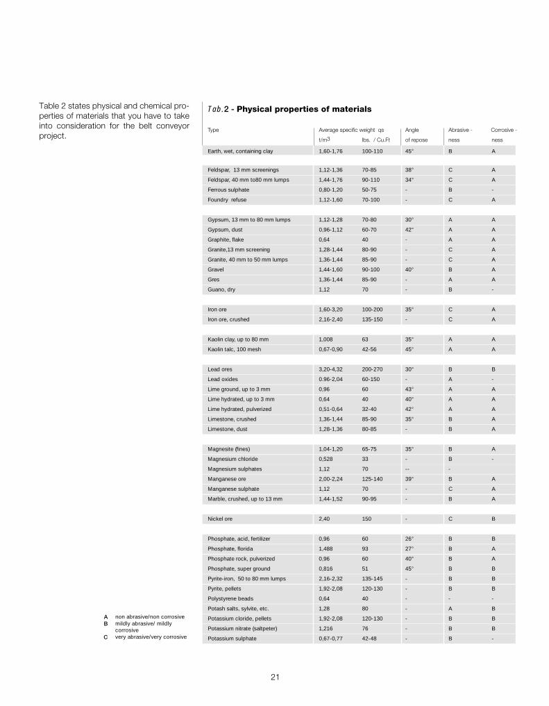
Tab.2 - Physical properties of materials
Type Average specific weight qs Angle Abrasive - Corrosive -
t/m3 lbs. / Cu.Ft of repose ness ness
Alumina 0,80-1,04 50-65 22° C A
Aluminium chips 0,11-0,24 7-15 - B A
Aluminium oxide 1,12-1,92 70-120 - C A
Aluminium sulphate (granular) 0,864 54 32° - -
Ammonium nitrate 0,72 45 - B C
Ammonium sulphate 0,72-0,93 45-58 32° B C
Asbestos ore or rock 1,296 81 - C A
Ashes, coal, dry, up to 80 mm 0,56-0,64 35-40 40° B A
Ashes, coal, wet, up to 80 mm 0,72-0,80 45-50 50° B P
Asphalt, binder for paving 1,28-136 80-85 - A B
Asphalt, crushed up to13 mm 0,72 45 - A A
Bakelite, fine 0,48-0,64 30-40 - A A
Barite 2,88 180 - A A
Barium carbonate 1,152 72 - A A
Bauxite, mine run 1,28-1,44 80-90 31° C A
Bauxite, ground, dried 1,09 68 35° C A
Bentonite, up to 100 mesh 0,80-0,96 50-60 - B A
Borax, lump 0,96-1,04 60-65 - B A
Brick, hard 2 125 - C A
Calcium carbide 1,12-1,28 70-80 - B B
Carbon black pellets 0,32-0,40 20-25 - A A
Carbon black powder 0,06-0,11 4-7 - A A
Carborundum, up to 80 mm 1,60 100 - C A
Cast iron chips 2,08-3,20 130-200 - B A
Cement, rock (see limestone) 1,60-1,76 100-110 - B A
Cement, Portland,aerated 0,96-1,20 60-75 39° B A
Charcoal 0,29-0,40 18-25 35° A A
Chrome ore (cromite) 2-2,24 125-140 - C A
Clay, dry, fine 1,60-1,92 100-120 35° C A
Clay, dry, lumpy 0,96-1,20 60-75 35° C A
Clinker 1,20-1,52 75-95 30-40° C A
Coal, anthracite 0,96 60 27° B A
Coal, bituminous, 50 mesh 0,80-0,86 50-54 45° A B
Coal, bituminous, run of mine 0,72-0,88 45-55 38° A B
Coal, lignite 0,64-0,72 40-45 38° A B
Coke breeze, 6 mm 0,40-0,5 25-35 30-45° C B
Coke, loose 0,37-0,56 23-35 - C B
Coke petroleum calcined 0,56-0,72 35-45 - A A
Concrete, in place, stone 2,08-2,40 130-150 - C A
Concrete, cinder 1,44-1,76 90-110 - C A
Copper, ore 1,92-2,40 120-150 - - -
Copper sulphate 1,20-1,36 75-85 31° A -
Cork 0,19-0,24 12-15 - - -
Cryolite 1,76 110 - A A
Cryolite, dust 1,20-1,44 75-90 - A A
Diacalcium phosphate 0,688 43 - - -
Disodium phosphate 0,40-0,50 25-31 -
Dolomite, lumpy 1,44-1,60 90-100 - B A
21
non abrasive/non corrosivemildly abrasive/ mildlycorrosivevery abrasive/very corrosive
AB
C
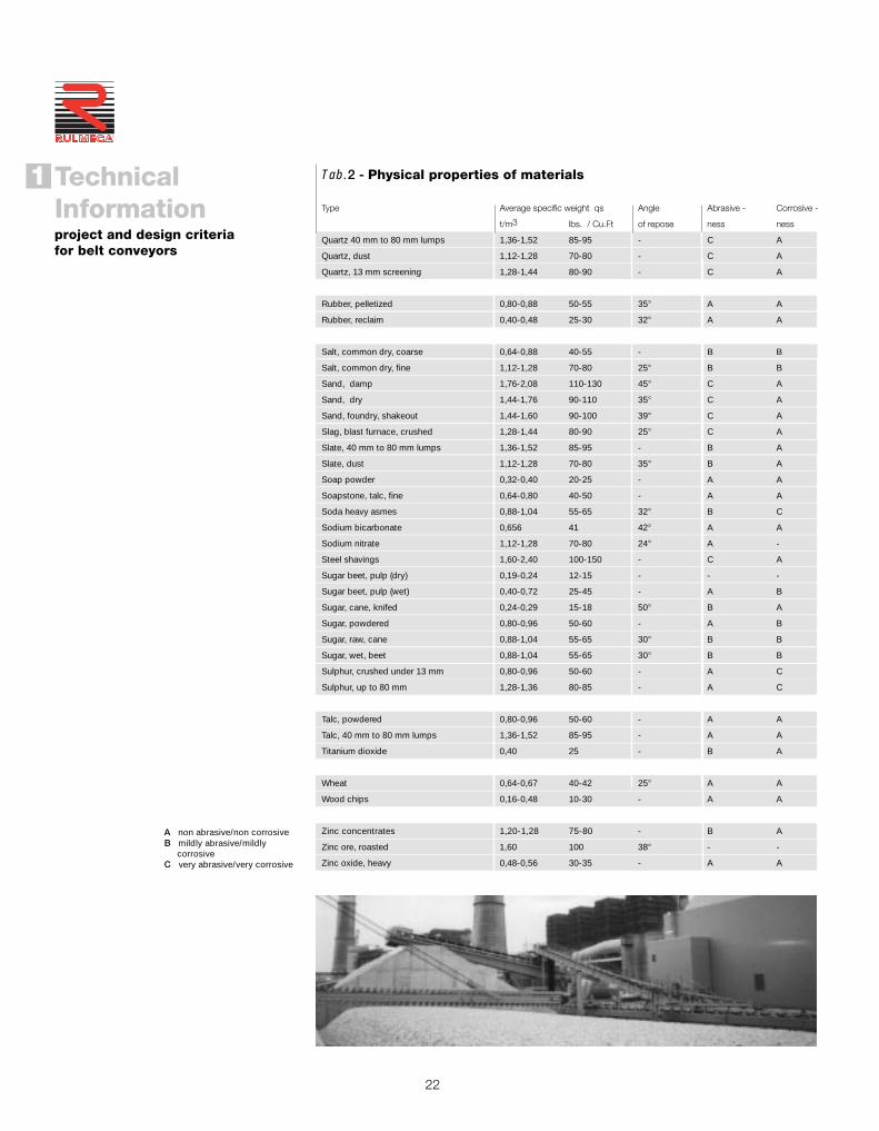
Tab.2 - Physical properties of materials
Type Average specific weight qs Angle Abrasive - Corrosive -
t/m3 lbs. / Cu.Ft of repose ness ness
Earth, wet, containing clay 1,60-1,76 100-110 45° B A
Feldspar, 13 mm screenings 1,12-1,36 70-85 38° C A
Feldspar, 40 mm to80 mm lumps 1,44-1,76 90-110 34° C A
Ferrous sulphate 0,80-1,20 50-75 - B -
Foundry refuse 1,12-1,60 70-100 - C A
Gypsum, 13 mm to 80 mm lumps 1,12-1,28 70-80 30° A A
Gypsum, dust 0,96-1,12 60-70 42° A A
Graphite, flake 0,64 40 - A A
Granite,13 mm screening 1,28-1,44 80-90 - C A
Granite, 40 mm to 50 mm lumps 1,36-1,44 85-90 - C A
Gravel 1,44-1,60 90-100 40° B A
Gres 1,36-1,44 85-90 - A A
Guano, dry 1,12 70 - B -
Iron ore 1,60-3,20 100-200 35° C A
Iron ore, crushed 2,16-2,40 135-150 - C A
Kaolin clay, up to 80 mm 1,008 63 35° A A
Kaolin talc, 100 mesh 0,67-0,90 42-56 45° A A
Lead ores 3,20-4,32 200-270 30° B B
Lead oxides 0.96-2,04 60-150 - A -
Lime ground, up to 3 mm 0,96 60 43° A A
Lime hydrated, up to 3 mm 0,64 40 40° A A
Lime hydrated, pulverized 0,51-0,64 32-40 42° A A
Limestone, crushed 1,36-1,44 85-90 35° B A
Limestone, dust 1,28-1,36 80-85 - B A
Magnesite (fines) 1,04-1,20 65-75 35° B A
Magnesium chloride 0,528 33 - B -
Magnesium sulphates 1,12 70 -- -
Manganese ore 2,00-2,24 125-140 39° B A
Manganese sulphate 1,12 70 - C A
Marble, crushed, up to 13 mm 1,44-1,52 90-95 - B A
Nickel ore 2,40 150 - C B
Phosphate, acid, fertilizer 0,96 60 26° B B
Phosphate, florida 1,488 93 27° B A
Phosphate rock, pulverized 0,96 60 40° B A
Phosphate, super ground 0,816 51 45° B B
Pyrite-iron, 50 to 80 mm lumps 2,16-2,32 135-145 - B B
Pyrite, pellets 1,92-2,08 120-130 - B B
Polystyrene beads 0,64 40 - - -
Potash salts, sylvite, etc. 1,28 80 - A B
Potassium cloride, pellets 1,92-2,08 120-130 - B B
Potassium nitrate (saltpeter) 1,216 76 - B B
Potassium sulphate 0,67-0,77 42-48 - B -
Table 2 states physical and chemical pro-perties of materials that you have to takeinto consideration for the belt conveyorproject.
22
TechnicalInformationproject and design criteriafor belt conveyors
1
®
A non abrasive/non corrosiveB mildly abrasive/mildly corrosiveC very abrasive/very corrosive
Tab.2 - Physical properties of materials
Type Average specific weight qs Angle Abrasive - Corrosive -
t/m3 lbs. / Cu.Ft of repose ness ness
Quartz 40 mm to 80 mm lumps 1,36-1,52 85-95 - C A
Quartz, dust 1,12-1,28 70-80 - C A
Quartz, 13 mm screening 1,28-1,44 80-90 - C A
Rubber, pelletized 0,80-0,88 50-55 35° A A
Rubber, reclaim 0,40-0,48 25-30 32° A A
Salt, common dry, coarse 0,64-0,88 40-55 - B B
Salt, common dry, fine 1,12-1,28 70-80 25° B B
Sand, damp 1,76-2,08 110-130 45° C A
Sand, dry 1,44-1,76 90-110 35° C A
Sand, foundry, shakeout 1,44-1,60 90-100 39° C A
Slag, blast furnace, crushed 1,28-1,44 80-90 25° C A
Slate, 40 mm to 80 mm lumps 1,36-1,52 85-95 - B A
Slate, dust 1,12-1,28 70-80 35° B A
Soap powder 0,32-0,40 20-25 - A A
Soapstone, talc, fine 0,64-0,80 40-50 - A A
Soda heavy asmes 0,88-1,04 55-65 32° B C
Sodium bicarbonate 0,656 41 42° A A
Sodium nitrate 1,12-1,28 70-80 24° A -
Steel shavings 1,60-2,40 100-150 - C A
Sugar beet, pulp (dry) 0,19-0,24 12-15 - - -
Sugar beet, pulp (wet) 0,40-0,72 25-45 - A B
Sugar, cane, knifed 0,24-0,29 15-18 50° B A
Sugar, powdered 0,80-0,96 50-60 - A B
Sugar, raw, cane 0,88-1,04 55-65 30° B B
Sugar, wet, beet 0,88-1,04 55-65 30° B B
Sulphur, crushed under 13 mm 0,80-0,96 50-60 - A C
Sulphur, up to 80 mm 1,28-1,36 80-85 - A C
Talc, powdered 0,80-0,96 50-60 - A A
Talc, 40 mm to 80 mm lumps 1,36-1,52 85-95 - A A
Titanium dioxide 0,40 25 - B A
Wheat 0,64-0,67 40-42 25° A A
Wood chips 0,16-0,48 10-30 - A A
Zinc concentrates 1,20-1,28 75-80 - B A
Zinc ore, roasted 1,60 100 38° - -
Zinc oxide, heavy 0,48-0,56 30-35 - A A
23
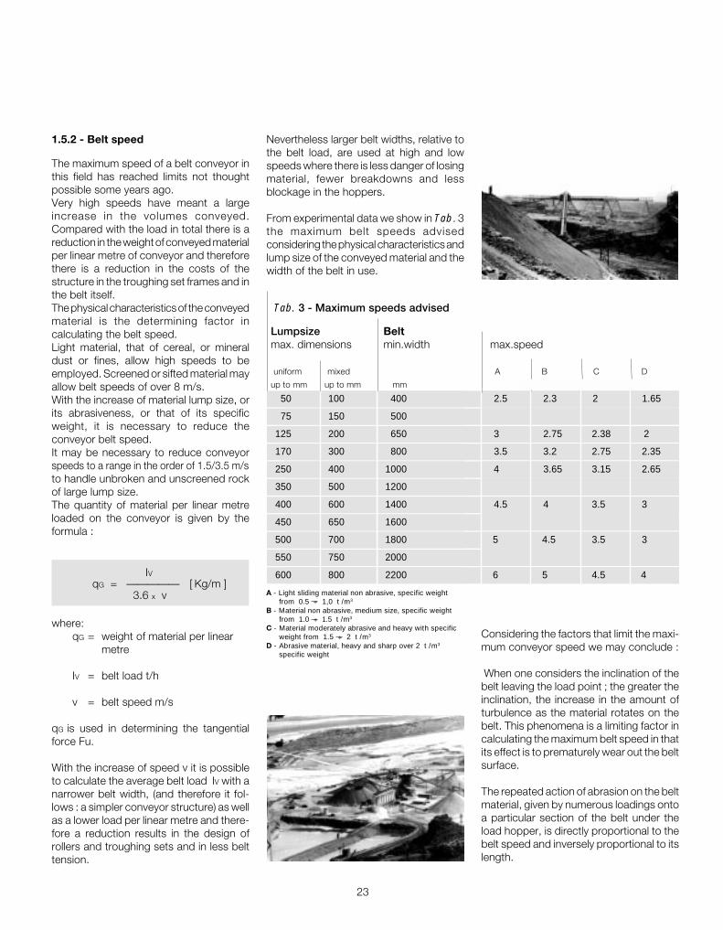
1.5.2 - Belt speed
The maximum speed of a belt conveyor inthis field has reached limits not thoughtpossible some years ago.Very high speeds have meant a largeincrease in the volumes conveyed.Compared with the load in total there is areduction in the weight of conveyed materialper linear metre of conveyor and thereforethere is a reduction in the costs of thestructure in the troughing set frames and inthe belt itself.The physical characteristics of the conveyedmaterial is the determining factor incalculating the belt speed.Light material, that of cereal, or mineraldust or fines, allow high speeds to beemployed. Screened or sifted material mayallow belt speeds of over 8 m/s.With the increase of material lump size, orits abrasiveness, or that of its specificweight, it is necessary to reduce theconveyor belt speed.It may be necessary to reduce conveyorspeeds to a range in the order of 1.5/3.5 m/sto handle unbroken and unscreened rockof large lump size.The quantity of material per linear metreloaded on the conveyor is given by theformula :
IV qG = ————— [ Kg/m ]
3.6 x v
where:qG = weight of material per linear
metre
IV = belt load t/h
v = belt speed m/s
qG is used in determining the tangentialforce Fu.
With the increase of speed v it is possibleto calculate the average belt load IV with anarrower belt width, (and therefore it fol-lows : a simpler conveyor structure) as wellas a lower load per linear metre and there-fore a reduction results in the design ofrollers and troughing sets and in less belttension.
Considering the factors that limit the maxi-mum conveyor speed we may conclude :
When one considers the inclination of thebelt leaving the load point ; the greater theinclination, the increase in the amount ofturbulence as the material rotates on thebelt. This phenomena is a limiting factor incalculating the maximum belt speed in thatits effect is to prematurely wear out the beltsurface.
The repeated action of abrasion on the beltmaterial, given by numerous loadings ontoa particular section of the belt under theload hopper, is directly proportional to thebelt speed and inversely proportional to itslength.
Tab. 3 - Maximum speeds advised
Lumpsize Beltmax. dimensions min.width max.speed
uniform mixed A B C D
up to mm up to mm mm
50 100 400 2.5 2.3 2 1.65
75 150 500
125 200 650 3 2.75 2.38 2
170 300 800 3.5 3.2 2.75 2.35
250 400 1000 4 3.65 3.15 2.65
350 500 1200
400 600 1400 4.5 4 3.5 3
450 650 1600
500 700 1800 5 4.5 3.5 3
550 750 2000
600 800 2200 6 5 4.5 4
A - Light sliding material non abrasive, specific weight from 0.5 ÷ 1,0 t /m3
B - Material non abrasive, medium size, specific weight from 1.0 ÷ 1.5 t /m3
C - Material moderately abrasive and heavy with specific weight from 1.5 ÷ 2 t /m3
D - Abrasive material, heavy and sharp over 2 t /m3
specific weight
Nevertheless larger belt widths, relative tothe belt load, are used at high and lowspeeds where there is less danger of losingmaterial, fewer breakdowns and lessblockage in the hoppers.
From experimental data we show in Tab. 3the maximum belt speeds advisedconsidering the physical characteristics andlump size of the conveyed material and thewidth of the belt in use.

24
TechnicalInformationproject and design criteriafor belt conveyors
1
®
1.5.3 - Belt width
Given, using Tab.3, the optimum beltspeed, the determination of the belt widthis largely a function of the quantity of con-veyed material which is indicated by theproject data.
In the following section, the conveyorcapacity may be expressed as loaded vo-lume IVT [m3/h] per v= 1 m/sec.The inclination of the side rollers of a transom(from 20° to 45° ) defines the angle of thetroughing set Fig.7.
Fig. 7
All things being equal the width of the beltat the greatest angle corresponds to anincrease in the loaded volume IVT .
The design of the loaded troughing set isdecided also as a function of the capacityof the belt acting as a trough.
In the past the inclination of the side rollersof a troughing set has been 20° . Today theimprovements in the structure and materialsin the manufacture of conveyor belts allowsthe use of troughing sets with side rollersinclined at 30° / 35° .
Troughing sets at 40° / 45° are used inspecial cases, where because of thisonerous position the belts must be able toadapt to such an accentuated trough.
In practice the choice and design of atroughing set is that which meets therequired loaded volume, using a belt ofminimum width and therefore the mosteconomic.
N
β
λ
Troughing setangle
Angle of surchargeDistance from edges0,05 x N + 25 mm
Belt width
It may be observed however that the beltwidth must be sufficient to accept andcontain the loading of material onto the beltwhether it is of mixed large lump size or finematerial.

25
For belts with higher breaking loads than those indicated in the table, it is advisable to consult the actual belt manufacturer.
In the calculation of belt dimensions onemust take into account the minimum valuesof belt width as a function of the beltbreaking load and the side roller inclinationas shown in Tab.4 .
Loaded volume IMThe volumetric load on the belt is given bythe formula:
Iv IM = _______ [ m3/h ]
qs
where: Iv = load capacity of the belt [ t/h ] qs = specific weight of the material
Also defined as: IM
IVT = _______ [ m3/h ] v
where the loaded volume is expressedrelevant to the speed of 1 mtr/sec.
Tab. 4 - Minimum belt width in relation to belt breaking load and roller inclinations.
Breaking load Belt width
λ= 20/25° λ= 30/35° λ= 45°
N/mm mm
250 400 400 —
315 400 400 450
400 400 400 450
500 450 450 500
630 500 500 600
800 500 600 650
1000 600 650 800
1250 600 800 1000
1600 600 800 1000
It may be determined from Tab. 5a-b-c-d,that the chosen belt width satisfies therequired loaded volume IM as calculatedfrom the project data, in relation to thedesign of the troughing sets, the rollerinclination, the angle of material surchargeand to belt speed.

26
TechnicalInformationproject and design criteriafor belt conveyors
1
®
Belt Angle of IVT m3/h
width surcharge
mm β λ = 0°
5°
10°
1600 20°
25°
30°
5°
10°
1800 20°
25°
30°
5°
10°
2000 20°
25°
30°
5°
10°
2200 20°
25°
30°
5°
10°
2400 20°
25°
30°
5°
10°
2600 20°
25°
30°
5°
10°
2800 20°
25°
30°
5°
10°
3000 20°
25°
30°
Belt Angle of IVT m3/h
width surcharge
mm β λ = 0°
5° 3.6
10° 7.5
300 20° 15.4
25° 20.1
30° 25.2
5° 7.5
10° 15.1
400 20° 31.3
25° 39.9
30° 50.0
5° 12.6
10° 25.2
500 20° 52.2
25° 66.6
30° 83.5
5° 22.3
10° 45.0
650 20° 93.2
25° 119.5
30° 149.4
5° 35.2
10° 70.9
800 20° 146.5
25° 187.5
30° 198.3
5° 56.8
10° 114.4
1000 20° 235.8
25° 301.6
30° 377.2
5° 83.8
10° 167.7
1200 20° 346.3
25° 436.6
30° 554.0
5° 115.5
10° 231.4
1400 20° 478.0
25° 611.6
30° 763.2
152.6
305.6
630.7
807.1
1008.7
194.7
389.8
804.9
1029.9
1287.0
241.9
484.2
1000.0
1279.4
1599.1
295.5
591.1
1220.4
1560.8
1949.4
353.1
706.3
1458.3
1865.1
2329.5
415.9
831.9
1717.9
2197.1
2744.1
484.0
968.0
1998.7
2556.3
3192.8
557.1
1114.2
2300.4
2942.2
3674.8
Tab. 5a - Loaded volumewith flat roller sets v = 1 m/s
β

27
To obtain the effective loaded volume IM at the desired belt speed
use:
IM = IVT x v [ m3/h ]
Belt Angle of IVT m3/h
width surcharge
mm β
5°
10°
300 20°
25°
30°
5°
10°
400 20°
25°
30°
5°
10°
500 20°
25°
30°
5°
10°
650 20°
25°
30°
5°
10°
800 20°
25°
30°
5°
10°
1000 20°
25°
30°
λ = 20°
17.6
20.5
28.8
32.0
36.3
34.5
41.4
55.8
63.7
72.0
57.6
68.7
92.8
105.8
119.8
102.9
123.1
165.9
189.3
214.5
175.6
192.9
260.2
296.6
336.2
317.1
310.6
418.6
477.3
541.0
Tab. 5b - Loaded volumewith 2 roll troughing sets v = 1 m/s
β
λ

28
TechnicalInformationproject and design criteriafor belt conveyors
1
®
21.6
24.4
30.6
33.8
37.8
45.7
51.4
66.3
69.8
77.0
78.4
87.4
106.9
117.7
129.6
143.2
159.1
193.6
212.4
233.6
227.1
252.0
306.0
334.8
367.9
368.6
408.6
494.6
541.0
594.0
545.0
602.6
728.2
795.9
873.3
753.8
834.1
1006.9
1100.1
1206.3
18.7
21.6
28.8
32.4
36.3
39.6
45.3
59.4
66.6
74.5
68.0
78.4
101.1
112.6
126.0
124.9
142.9
183.6
204.4
227.8
198.3
226.8
290.1
322.9
359.2
322.9
368.6
469.8
522.0
580.6
477.0
543.9
692.6
768.9
855.0
661.3
753.4
957.9
1063.4
1181.8
17.2
20.5
27.7
31.6
36.0
36.6
43.2
57.2
65.1
73.4
62.6
73.4
97.2
109.8
123.8
114.4
134.2
176.4
198.7
223.5
182.1
212.7
278.2
313.2
352.4
296.2
345.6
450.7
506.5
569.1
438.1
510.1
664.2
745.9
837.7
606.9
706.3
918.7
1031.4
1157.7
15.1
18.7
26.2
30.2
34.9
32.4
29.2
54.3
62.2
70.9
55.8
67.3
91.8
104.7
119.1
101.8
122.4
166.3
189.7
215.2
162.0
194.4
262.8
299.1
339.4
263.8
315.3
425.5
483.8
548.6
389.8
465.4
627.1
712.8
807.4
540.7
644.7
867.6
985.3
1116.3
13.3
16.9
24.4
27.7
33.4
28.0
35.2
50.4
56.8
67.7
47.8
60.1
85.3
96.1
114.1
87.8
109.4
154.4
174.2
205.5
139.6
173.6
244.0
275.0
324.0
227.1
281.1
394.9
444.9
523.4
335.8
415.0
581.7
655.2
770.4
465.8
574.9
804.9
906.4
1064.8
Belt Angle of IVT m3/h
width surcharge
mm β λ = 20° λ = 25° λ = 30° λ = 35° λ = 45°
5°
10°
300 20°
25°
30°
5°
10°
400 20°
25°
30°
5°
10°
500 20°
25°
30°
5°
10°
650 20°
25°
30°
5°
10°
800 20°
25°
30°
5°
10°
1000 20°
25°
30°
5°
10°
1200 20°
25°
30°
5°
10°
1400 20°
25°
30°
Tab. 5c - Loaded volume with 3 roll troughing sets v = 1 m/s

29
997.5
1102.6
1330.2
1452.9
1593.0
1274.7
1409.0
1698.8
1854.7
2032.9
1586.5
1752.8
2112.1
2305.8
2526.8
1908.1
2109.2
2546.2
2777.9
3045.5
2275.5
2514.2
3041.2
3317.9
3636.4
2697.3
2981.5
3592.0
3918.8
4295.0
3119.7
3448.4
4168.4
4547.7
4984.2
3597.8
3976.9
4800.2
5237.0
5739.7
875.5
997.2
1266.4
1405.4
1561.3
1119.6
1274.4
1617.8
1794.9
1993.6
1393.9
1586.1
2012.0
2231.6
2478.6
1691.3
1925.2
2433.2
2698.4
2995.2
2010.7
2288.8
2896.2
3211.8
3565.0
2382.4
2711.8
3425.0
3798.3
4216.1
2759.4
3141.0
3971.5
4404.3
4888.7
3184.8
3625.2
4579.5
5078.6
5637.2
803.8
934.5
1214.2
1363.3
1529.6
1027.8
1194.4
1551.2
1740.0
1953.0
1279.8
1486.4
1929.2
2164.6
2427.8
1545.4
1796.0
2331.7
2613.6
2930.0
1832.9
2130.1
2776.3
3112.2
3488.7
2175.9
2528.6
3281.7
3678.7
4123.8
2517.8
2926.0
3805.5
4265.9
5185.6
2905.6
3376.8
4390.9
4922.1
5517.6
716.0
853.2
1146.9
1302.1
1474.9
915.4
1090.8
1465.2
1663.2
1883.1
1139.7
1357.2
1822.3
2068.2
2341.4
1371.5
1634.4
2199.9
2496.8
2826.3
1632.9
1945.8
2618.6
2972.1
3364.4
1936.7
2307.9
3099.6
3518.0
3982.3
2240.7
2670.1
3592.0
4076.9
4615.0
2585.8
3079.0
4140.3
4699.2
5319.4
To obtain the effective loaded volume IM at the desired belt
speed use:
IM = IVT x v [ m3/h ]
Belt Angle of IVT m3/h
width surcharge
mm β λ = 20° λ = 25° λ = 30° λ = 35° λ = 45°
5°
10°
1600 20°
25°
30°
5°
10°
1800 20°
25°
30°
5°
10°
2000 20°
25°
30°
5°
10°
2200 20°
25°
30°
5°
10°
2400 20°
25°
30°
5°
10°
2600 20°
25°
30°
5°
10°
2800 20°
25°
30°
5°
10°
3000 20°
25°
30°
616.6
760.6
1063.8
1198.0
1432.8
788.7
972.3
1353.2
1530.7
1796.4
981.7
1209.9
1690.0
1903.6
2233.4
1185.1
1461.1
2048.0
2316.2
2716.9
1403.7
1730.5
2431.0
2749.4
3225.0
1670.0
2058.8
2886.4
3264.5
3829.2
1930.8
2380.3
3342.6
3780.0
4433.9
2227.0
2745.7
3851.2
4355.7
5109.2
β
λ

30
TechnicalInformationproject and design criteriafor belt conveyors
1
®
1679.7
1846.0
2185.2
2381.7
2595.9
2049.1
2251.1
2661.8
2901.2
3162.2
2459.8
2703.2
3185.2
3471.8
3784.3
2899.4
3186.3
3755.1
4092.8
4461.4
3379.3
3713.7
4372.2
4765.6
5194.4
3863.5
4245.8
5018.4
5469.8
5962.3
236.5
260.2
313.9
342.0
372.9
388.8
427.3
510.4
556.2
606.2
573.1
630.0
751.3
816.6
892.4
797.4
876.6
1041.4
1135.0
1237.3
1075.3
1181.8
1371.9
1495.0
1629.7
1343.1
1476.0
1749.6
1906.9
2078.6
Belt Angle of IVT m3/h
width surcharge
mm β λλλλλ1 30° λλλλλ2 60°
5°
10°
800 20°
25°
30°
5°
10°
1000 20°
25°
30°
5°
10°
1200 20°
25°
30°
5°
10°
1400 20°
25°
30°
5°
10°
1600 20°
25°
30°
5°
10°
1800 20°
25°
30°
Belt Angle of IVT m3/h
width surcharge
mm β λ λ λ λ λ1 30° λλλλλ2 60°
5°
10°
2000 20°
25°
30°
5°
10°
2200 20°
25°
30°
5°
10°
2400 20°
25°
30°
5°
10°
2600 20°
25°
30°
5°
10°
2800 20°
25°
30°
5°
10°
3000 20°
25°
30°
Tab. 5d - Loaded volume with 5 roll troughing sets v = 1 m/s
To obtain the effective loaded volume IM at desired belt speed
use:
IM = IVT x v [ m3/h ]
β
λ1λ2
31
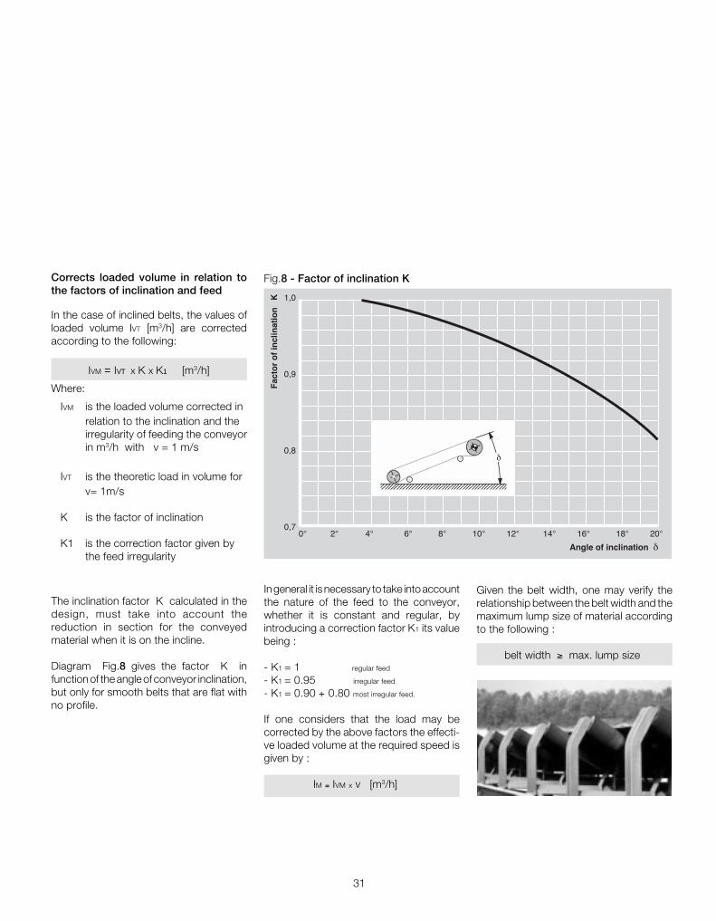
In general it is necessary to take into accountthe nature of the feed to the conveyor,whether it is constant and regular, byintroducing a correction factor K1 its valuebeing :
- K1 = 1 regular feed
- K1 = 0.95 irregular feed
- K1 = 0.90 ÷ 0.80 most irregular feed.
If one considers that the load may becorrected by the above factors the effecti-ve loaded volume at the required speed isgiven by :
IM = IVM x v [m3/h]
In the case of inclined belts, the values ofloaded volume IVT [m3/h] are correctedaccording to the following:
IVM = IVT X K X K1 [m3/h]
Where:
IVM is the loaded volume corrected inrelation to the inclination and theirregularity of feeding the conveyorin m3/h with v = 1 m/s
IVT is the theoretic load in volume forv= 1m/s
K is the factor of inclination
K1 is the correction factor given bythe feed irregularity
0° 2° 4° 6° 8° 10° 12° 14° 16° 18° 20°
Angle of inclination δ
Fac
tor
of
incl
inat
ion
K 1,0
0,9
0,8
0,7
δ
Fig.8 - Factor of inclination KCorrects loaded volume in relation tothe factors of inclination and feed
The inclination factor K calculated in thedesign, must take into account thereduction in section for the conveyedmaterial when it is on the incline.
Diagram Fig.8 gives the factor K infunction of the angle of conveyor inclination,but only for smooth belts that are flat withno profile.
Given the belt width, one may verify therelationship between the belt width and themaximum lump size of material accordingto the following :
belt width ≥ max. lump size

32
TechnicalInformationproject and design criteriafor belt conveyors
1
®
The roller frame with fixed supports, withthree rollers of equal length, support thebelt well with a uniform distribution of forcesand load sharing.The inclination of the side roller varies from20° up to 45° for belts of 400 mm width upto 2200mm and over.
The suspended sets of “garland” designare used incorporating impact rollers toaccept the impact under the load hopper,and also in use along the conveyor upperand lower strands where large loads maybe carried or on very high performanceconveyors.
The troughing sets are generally designedand manufactured according to internat-ional unified standards.
The drawings illustrate the more commonarrangements.
1 1.5.4 - Type of troughing set, pitch andtransition distance
TypeFor each troughing set there is a combina-tion of rollers positioned into a suitablefixed support frame Fig. 9 ; the troughingsets may also be suspended as a “garland”Fig. 10.
There are 2 basic types of troughing setbase frame : the upper set, , which carriesthe loaded belt on the upper strand, andthe lower set, which supports the emptybelt on the return strand.
• The upper carrying troughing set is gene-rally designed as the following arrange-ment :- one or two parallel rollers- two, three or more rollers in a trough.
• The return set can be with :- one or two flat rollers- a trough of two rollers.
- 3 rollers plain or impact
- roller plain or with rubber rings- parallel roller plain or impact
- 2 rollers plain or with rings- 2 rollers plain or impact
Fig. 9 - Troughing sets upper strand Return sets

33
Fig. 12 - only for uni-directional belts
Fig.13 - misalignment of the troughing setmay promote belt wandering.
The choice of the most appropriate andcorrect troughing set installation (one needsto calculate the frictional force between therollers and the belt itself) is the guaranteefor the smooth belt start up and move-ment.
The troughing sets on the upper strand ofa reversible belt may have the rollers in linewith each other and at right angles to thebelt as in Fig. 11; in the case of non-reversible belt the side rollers are inclinedforward by 2° in the same sense of direct-ion of the belt, as in Fig. 12.
Direction of travel
Fig. 11 - for reversible belts
Direction of travel Direction of travel
- 3 rollers plain for loadcarrying
- 2 rollers plain or with rubber rings for returnset
- 5 rollers plain for loadcarrying
Fig. 10 - suspension sets "garland"

34
TechnicalInformationproject and design criteriafor belt conveyors
1
®
ai
Tab. 6 - Maximum advised pitch of troughing sets
Belt Pitch of setswidth upper lower
specific weight of conveyed material t/m3
< 1.2 1.2 ÷ 2.0 > 2.0
m m m m m
300 1.65 1.50 1.40 3.0
400
500
650
800 1.50 1.35 1.25 3.0
1000 1.35 1.20 1.10 3.0
1200 1.20 1.00 0.80 3.0
1400
1600
1800
2000 1.00 0.80 0.70 3.0
2200
to maintain a deflection of the belt withinthe indicated limits. Above all the pitch isalso limited by the load capacity of therollers themselves.
At the loading points the pitch is generallyone half or less, that of the normal pitch oftroughing sets so that any belt deflection islimited to the least possible ; and also toreduce the load forces on the rollers.
The calculation of the minimum pitch forsuspension sets is calculated to avoid con-tact between adjoining “garlands” whenthe normal oscillation of the sets takesplace during belt operation Fig.15.
Troughing set pitchThe trough set pitch ao most commonlyused for the upper strand of a belt con-veyor is 1 metre, whilst for the return strandthe sets are pitched normally at 3 metres(au).
The deflection of the belt between 2 con-secutive carrying troughing sets shouldnot be more than 2 % of the pitch itself.A greater deflection causes the dischargeof the material during the loading and pro-motes excessive frictional forces duringthe belt movement due to the manipulationof the material being conveyed. This notonly the increases the horse power andwork, but also increases forces on therollers, and overall a premature belt surfacewear occurs.
Tab.6 advises the maximum pitch fortroughing sets in relation to belt width andthe specific weight of the conveyed material,
ai ao
au Fig.14
Fig.15

35
Lt
aoat at at ao ao
au
Transition distance LtThe distance between the last troughingset adjacent to the head or tail pulley of aconveyor and the pulleys themselves isknown as the transition distance Fig.16.
Fig.16
Along this section the belt changes from atrough configuration as determined by theinclination of the rollers of the carrying setsto a flat belt to match the flat pulley and viceversa.
The edges of the belt are in this area placedunder an extra force which reacts on theside rollers, Generally the transitiondistance must not be less than the beltwidth to avoid excess pressures.
Lt
Example:For a belt (EP) 1400mm width troughingsets at 45°, one may extract from the graphthat the transition distance is about3 metres.It is advisable to position in this section Lttwo troughing sets with respectively λ=15°and 30° at a pitch of 1 metre.
In the case where the transition distance Ltis larger than the pitch of the carryingtroughing sets it is a good rule to introducein this transition area troughing sets withinclined side rollers of gradual reduction inangle (known as transition troughing sets).In this way the belt may change graduallyfrom trough to flat avoiding those dama-ging forces.
The graph Fig.19 allows the determina-tion of the transition distance Lt ( inrelation to the belt width and to the inclina-tion of the side rollers of the troughingsets), for belts with textile structure EP(polyester) and for steel corded belts (ST).
λ
4 2
2 1
650 800 1000 1200 1400 1600 1800 2000 2200
Belt width mm
Valu
e of
Lt i
n m
etre
s fo
r st
eel c
ord
belts
(S
T)
Valu
e of
Lt
in m
etre
s fo
r te
xtile
str
uctu
red
belts
(E
P)
λ = 20°
λ = 30°
λ = 45°
6
8
10
3
4
5
λ
Fig.19 - Transition distance
Fig.18
30°15°
45°
Fig.17
36
TechnicalInformationproject and design criteriafor belt conveyors
1
®
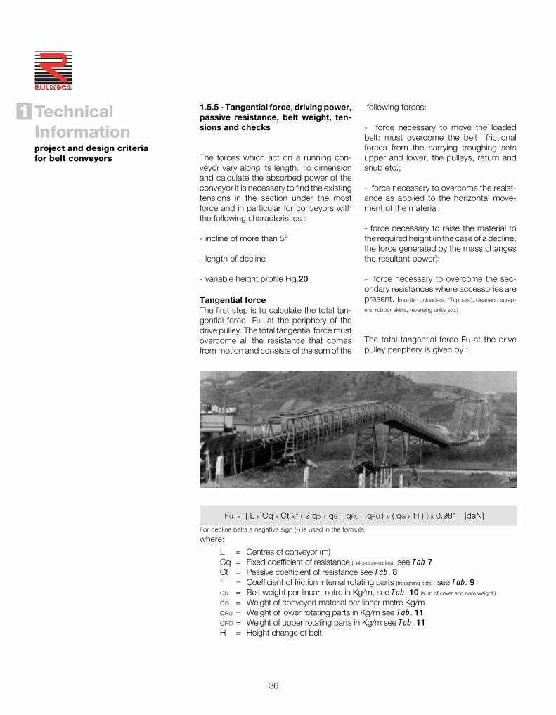
1.5.5 - Tangential force, driving power,passive resistance, belt weight, ten-sions and checks
The forces which act on a running con-veyor vary along its length. To dimensionand calculate the absorbed power of theconveyor it is necessary to find the existingtensions in the section under the mostforce and in particular for conveyors withthe following characteristics :
- incline of more than 5°
- length of decline
- variable height profile Fig.20
FU = [ L x Cq x Ct x f ( 2 qb + qG + qRU + qRO ) ± ( qG x H ) ] x 0.981 [daN]
For decline belts a negative sign (-) is used in the formula
where:
Tangential forceThe first step is to calculate the total tan-gential force FU at the periphery of thedrive pulley. The total tangential force mustovercome all the resistance that comesfrom motion and consists of the sum of the
following forces:
- force necessary to move the loadedbelt: must overcome the belt frictionalforces from the carrying troughing setsupper and lower, the pulleys, return andsnub etc.;
- force necessary to overcome the resist-ance as applied to the horizontal move-ment of the material;
- force necessary to raise the material tothe required height (in the case of a decline,the force generated by the mass changesthe resultant power);
- force necessary to overcome the sec-ondary resistances where accessories arepresent. (mobile unloaders, “Trippers”, cleaners, scrap-
ers, rubber skirts, reversing units etc.)
The total tangential force Fu at the drivepulley periphery is given by :
L = Centres of conveyor (m)Cq = Fixed coefficient of resistance (belt accessories), see Tab 7Ct = Passive coefficient of resistance see Tab. 8f = Coefficient of friction internal rotating parts (troughing sets), see Tab. 9qb = Belt weight per linear metre in Kg/m, see Tab. 10 (sum of cover and core weight )
qG = Weight of conveyed material per linear metre Kg/mqRU = Weight of lower rotating parts in Kg/m see Tab. 11qRO = Weight of upper rotating parts in Kg/m see Tab. 11H = Height change of belt.

37
When it is necessary to calculate theforces on a variable altitude belt conveyorit may be seen that the total tangentialforce is made up from forces Fa (tangentialforce to move the belt, upper strand) andthe lesser force Fr (tangential force onreturn strand)all necessary to move a sin-gle uniform section of the belt that comp-rises the conveyor (Fig.20) thus we have:
FU=(Fa1+Fa2+Fa3...)+(Fr1+Fr2+Fr3...)
Where:Fa = tangential force to move a single
section of the belt upper strandFr = tangential force to move a single
section of the belt lower strand
Fa = [ L x Cq x Ct x f ( qb + qG + qRO ) ± ( qG + qb) x H ] x 0.981 [daN]
Fr = [ L x Cq x Ct x f ( qb + qRU ) ± ( qb x H) ] x 0.981 [daN]
Using the indication (+) for belt sections that rise (-) for sections that fall
Therefore the tangential force Fa and Fr will be given by:
Driving powerNoting the total tangential force at theperiphery of the drive pulley, the belt speedand the efficiency ( η ) of the reductiongear, the minimum necessary drivingpower is :
FU x v P = ———— [kW] 100 x ηηηηη
L 4L 3L 2L 1
H1 H2 H3
H
Fig.20 - Varying altitude profile

38
TechnicalInformationproject and design criteriafor belt conveyors
1
®
Passive resistanceThe passive resistance is expressed by acoefficient which is dependant on the lengthof the belt conveyor, ambient temperature,speed, type of maintenance, cleanlinessand fluidity of movement, internal friction ofthe conveyed material, and to the convey-or inclinations.
Tab. 7 - Coefficient of fixed resistance
Centres Cqm
10 4.5
20 3.2
30 2.6
40 2.2
50 2.1
60 2.0
80 1.8
100 1.7
150 1.5
200 1.4
250 1.3
300 1.2
400 1.1
500 1.05
1000 1.03
Rotating parts and material
with standard internal friction
Rotating parts and material
with high internal friction in
difficult working conditions
Rotating parts of a conveyor
in descent with a brake motor
and/or generator
Horizontal belt conveyor
rising and gently falling
velocità m/s
1 2 3 4 5 6
0,0160 0,0165 0,0170 0,0180 0,0200 0,0220
da 0,023 a 0,027
da 0,012 a 0,016
Tab. 8 - Coefficient of passive resistance given by temperature
Temperature °C + 20° + 10° 0 - 10° - 20° - 30°
Factor Ct 1 1,01 1,04 1,10 1,16 1,27
Tab. 9 - Coefficient of internal friction f of materials and of the rotating parts
speed m/s
39
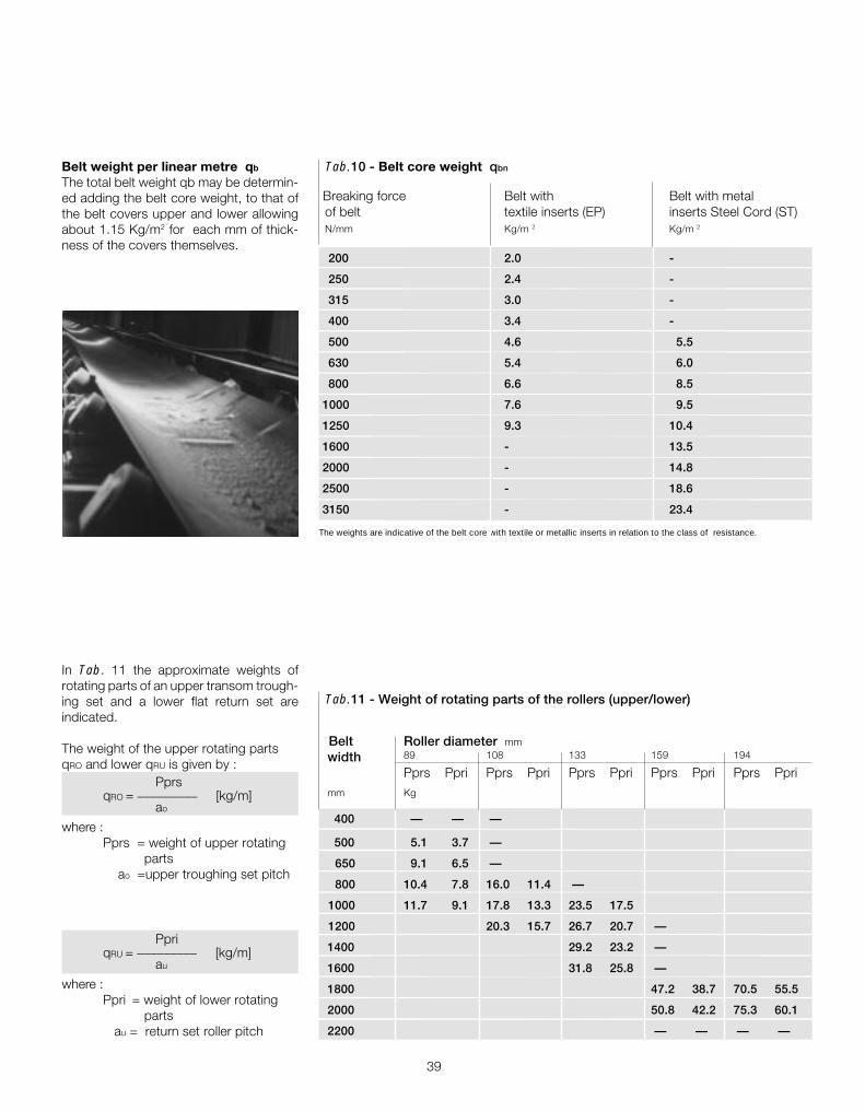
Belt weight per linear metre qb
The total belt weight qb may be determin-ed adding the belt core weight, to that ofthe belt covers upper and lower allowingabout 1.15 Kg/m2 for each mm of thick-ness of the covers themselves.
Tab.10 - Belt core weight qbn
Belt Roller diameter mm
width 89 108 133 159 194
Pprs Ppri Pprs Ppri Pprs Ppri Pprs Ppri Pprs Pprimm Kg
400 — — —
500 5.1 3.7 —
650 9.1 6.5 —
800 10.4 7.8 16.0 11.4 —
1000 11.7 9.1 17.8 13.3 23.5 17.5
1200 20.3 15.7 26.7 20.7 —
1400 29.2 23.2 —
1600 31.8 25.8 —
1800 47.2 38.7 70.5 55.5
2000 50.8 42.2 75.3 60.1
2200 — — — —
In Tab. 11 the approximate weights ofrotating parts of an upper transom trough-ing set and a lower flat return set areindicated.
The weight of the upper rotating partsqRO and lower qRU is given by :
PprsqRO = _________ [kg/m]
ao
where :Pprs = weight of upper rotating
parts ao =upper troughing set pitch
PpriqRU = _________ [kg/m]
au
where :Ppri = weight of lower rotating
parts au = return set roller pitch
The weights are indicative of the belt core with textile or metallic inserts in relation to the class of resistance.
Breaking force Belt with Belt with metalof belt textile inserts (EP) inserts Steel Cord (ST)N/mm Kg/m 2 Kg/m 2
200 2.0 -
250 2.4 -
315 3.0 -
400 3.4 -
500 4.6 5.5
630 5.4 6.0
800 6.6 8.5
1000 7.6 9.5
1250 9.3 10.4
1600 - 13.5
2000 - 14.8
2500 - 18.6
3150 - 23.4
Tab.11 - Weight of rotating parts of the rollers (upper/lower)

40
TechnicalInformationproject and design criteriafor belt conveyors
1
®
Belt tensionIt is necessary to consider the differenttensions that must be verified in a conveyorwith a powered belt system.
Tensions T1 e T2
The total tangential force FU at the pulleycircumference corresponds to the differ-ences between tensionsT1 (tight side) andT2 (output side). From these is derived thenecessary torque to begin to move the beltand transmit power.
Fig.21
Moving from point A to point B Fig. 21 thebelt tension changes exponentially fromvalue T1 to value T2.
The relationship between T1 and T2 maybe expressed :
T1
——— ≤ efa
T2
where:fa = coefficient of friction between belt
and drum, given by the angle of wrap
e = natural logarithmic base 2.718
The sign (=) defines the limiting conditionof belt adherence. If the ratio T1/T2 > ef a
the belt will slide on the drive pulley and themovement cannot be transmitted.
From the above formula we may obtain :
T1 = FU + T2
1 T2 = FU —————— = FU x Cw
efa - 1
The value Cw, which defines the wrapfactor, is a function of the angle of wrap ofthe belt on the drive pulley (may 420° whenthere are double pulleys) and the value ofthe coefficient of friction fa between thebelt and pulley.
Thus the calculation of the minimum belttension values is able to be made to thelimit of adherence of the belt on the pulleyso that the position of a tensioner may bepositioned downstream of the drive pulley.
A belt tensioning device may be used asnecessary to increase the adherence of thebelt to the drive pulley. This will be used tomaintain an adequate tension in all workingconditions.
On the following pages various types of belttensioning devices commonly used aredescribed.
FU = T1 - T2
T1
T2
T2
Fu
A
B
α

41
Given the values T1 and T2 ,we may analysethe belt tensions in other areas that arecritical to the conveyor. These are :
- Tension T3 relative to the slack section of the return pulley;
- Tension T0 minimum at tail end, in the material loading area;
- Tension Tg of the belt at the point of connection to the tension unit device;
- Tension Tmax maximum belt tension.
T0 =T3
T3
T1
T2
Fig. 22
Tension T3
As already defined,
T1 = Fu +T2 and T2 = FU x Cw
The tension T3 that is generated at the beltslackside of the tail pulley ( Fig. 22 ) is givenfrom the algebraic sum of the tensions T2
and the tangential forces Fr relative to asingle return section of the belt.
Therefore the tension T3 is given by :
T3 = T2 + ( Fr1 + Fr2 + Fr3 ... ) [daN]
Tab. 12 gives the value of the wrap factorCw in relation to the angle of wrap, thesystem of tensioning and the use of thepulley in a lagged or unlagged condition.
fattore di avvolgimento CW
tension unit or counterweight screw tension unit
pulley pulley
unlagged lagged unlagged lagged
180° 0.84 0.50 1.2 0.8
200° 0.72 0.42 1.00 0.75
210° 0.66 0.38 0.95 0.70
220° 0.62 0.35 0.90 0.65
240° 0.54 0.30 0.80 0.60
380° 0.23 0.11 - -
420° 0.18 0.08 - -
Angle ofwrapα
drivearrangement
Tab. 12 - Wrap factor Cw
T1
T2
T1
T2
T1
T2
42
TechnicalInformationproject and design criteriafor belt conveyors
1
®
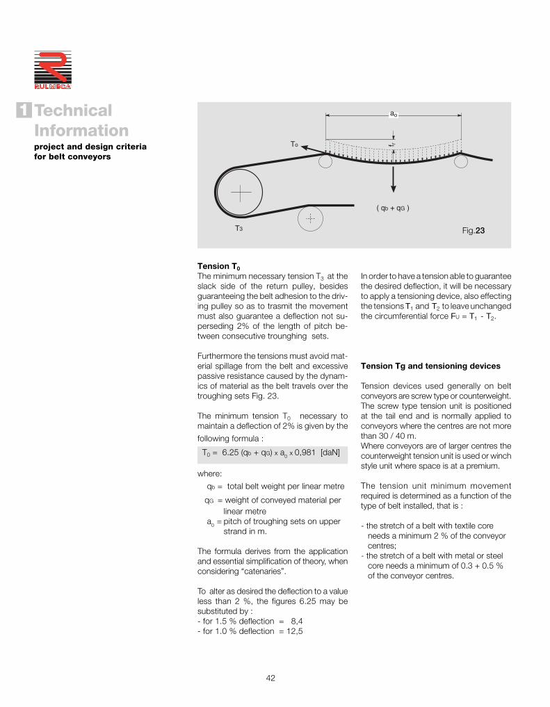
Tension T0
The minimum necessary tension T3 at theslack side of the return pulley, besidesguaranteeing the belt adhesion to the driv-ing pulley so as to trasmit the movementmust also guarantee a deflection not su-perseding 2% of the length of pitch be-tween consecutive trounghing sets.
Furthermore the tensions must avoid mat-erial spillage from the belt and excessivepassive resistance caused by the dynam-ics of material as the belt travels over thetroughing sets Fig. 23.
The minimum tension T0 necessary tomaintain a deflection of 2% is given by the
following formula :
T0 = 6.25 (qb + qG) x a0 x 0,981 [daN]
where:
qb = total belt weight per linear metre
qG = weight of conveyed material perlinear metre
a0 = pitch of troughing sets on upperstrand in m.
The formula derives from the applicationand essential simplification of theory, whenconsidering “catenaries”.
To alter as desired the deflection to a valueless than 2 %, the figures 6.25 may besubstituted by :- for 1.5 % deflection = 8,4- for 1.0 % deflection = 12,5
In order to have a tension able to guaranteethe desired deflection, it will be necessaryto apply a tensioning device, also effectingthe tensions T1 and T2 to leave unchangedthe circumferential force FU = T1 - T2.
Tension Tg and tensioning devices
Tension devices used generally on beltconveyors are screw type or counterweight.The screw type tension unit is positionedat the tail end and is normally applied toconveyors where the centres are not morethan 30 / 40 m.Where conveyors are of larger centres thecounterweight tension unit is used or winchstyle unit where space is at a premium.
The tension unit minimum movementrequired is determined as a function of thetype of belt installed, that is :
- the stretch of a belt with textile core needs a minimum 2 % of the conveyor centres;- the stretch of a belt with metal or steel core needs a minimum of 0.3 + 0.5 % of the conveyor centres.
T3
( qb + qG )
To f r
ao
Fig.23

43
Typical tension deviceMaximum tension (Tmax )This is the belt tension at the point wherethe conveyor is under the greatest stress.
Normally it is coincidental in value withtension T1 . Along the length of a conveyorwith variable height change and in partic-ular where conditions are variable andextreme, Tmax may be found in differentsections of the belt.
T1
T2T3
T3
In this arrangement the tension is regulatednormally with the occasional periodic checkof the tensioning screw.
Also in this arrangement the conveyor istensioned using a counterweight.
T1
T2
T3
T3
Tg
Ht
Ic
In this arrangement the conveyor istensioned using a counterweight.
Tg = 2 ( T3 ) [daN]
T1
T2T3
T3
Tg
Fig.24
Fig.25
Fig.26
Tg = 2T2 + 2 [( IC x Cq x Ct x f ) ( qb + qRU ) ± ( Ht x qb )] 0,981 [daN]
In which: IC = distance from centre of drive pulley to the counterweight attachment point Ht = belt height change from the point where the counterweight applies itself to the
point where the belt exits from the slack side of the pulley, measured in metres.
Correct dimensioning verificationThe belt will be adequately dimensioned when the essential tension T0 (for the correctdeflection of the belt) is less than the calculated tension T3 the tension T2 has always tobe T2 ≥ Fu x Cw and is calculated as T2 = T3 ± Fr (where T3 ≥ T0 )
Working load and belt breaking strainTmax is used to calculate the unitary maxi-mum tension of the belt Tumax given that:
Tmax x 10 Tumax = —————— [N/mm] N
where: N = belt width in mm;
Tmax = tension at the highest stress point of the belt in daN.
As a security factor one may consider themaximum working load of the belt withtextile core to correspond to 1/10 of thebreaking load of the belt (1/8 for a belt withsteel core).

44
TechnicalInformationproject and design criteriafor belt conveyors
1
®
1.5.6 - Belt conveyor drives andpulley dimensions
Type of drivesConveyors requiring power up to 132 kWare traditionally driven at the head pulleywith electric motor, gearbox, pulley, guards,transmission accessories etc., or, alternat-ively by motorised pulley. Fig.27.
Fig.27
The motorised pulley is used today moreand more as the drive for belt conveyorsthanks to its characteristics andcompactness. It occupies a minimal space,is easy to install, its motor is protected toIP67, all working parts are inside the pulleyand therefore it needs very limited andoccasional maintenance (oil change every10,000 working hours).
In the drawings Fig.28 a comparison ismade between the space needed for twodrive systems.
Belt conveyors that need power over 132kW utilise the conventional drive pulleyarrangement but also with two or moremotor gearboxes.
Fig.28

45
belt with textile core EP DIN 22102
Minimum diameters recommended for pulleys in mm up to 100% of the maximum working load as recommendedRMBT ISO bis/3654
belt with steel core STDIN 22131
Ø motorised return direction Ø motorised return directionpulley pulley change pulley pulley change
N/mm mm drum mm pulley
200 200 160 125 - - -
250 250 200 160 - - -
315 315 250 200 - - -
400 400 315 250 - - -
500 500 400 315 - - -
630 630 500 400 - - -
800 800 630 500 630 500 315
1000 1000 800 630 630 500 315
1250 1250 1000 800 800 630 400
1600 1400 1250 1000 1000 800 500
2000 - - - 1000 800 500
2500 - - - 1250 1000 630
3150 - - - 1250 1000 630
Tab. 13 -Minimum pulley diameters recommended
This table must not be applied to belt conveyors that convey material with a temperatureover +110 °C or for conveyors installed where the ambient temperature is less than - 40 °C.
belt breakingl load
Pulley diametersThe dimensioning of the diameter of a headpulley is in strict relationship to thecharacteristics of the type of belt used.
In Tab. 13 the minimum diameters recom-mended in relation to the type of belt usedare indicated, avoiding damaging de-layering of the belt layers or laceration ofthe reinforcing fabric.
46
TechnicalInformationproject and design criteriafor belt conveyors
1
®
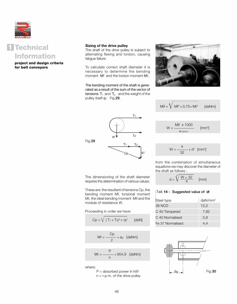
The bending moment of the shaft is gene-rated as a result of the sum of the vector oftensions T1 and T2 and the weight of thepulley itself qT Fig.29.
Fig.29
Sizing of the drive pulleyThe shaft of the drive pulley is subject toalternating flexing and torsion, causingfatigue failure.
To calculate correct shaft diameter it isnecessary to determine the bendingmoment Mf and the torsion moment Mt.
The dimensioning of the shaft diameterrequires the determination of various values.
These are: the resultant of tensions Cp, thebending moment Mf, torsional momentMt, the ideal bending moment Mif and themodule of resistance W.
Proceeding in order we have:
Cp = � ( T1 + T2)2 + qt2 [daN]
CpMf = ______ x ag [daNm]
2
PMt = ______ x 954,9 [daNm]
n
where:P = absorbed power in kWn = r.p.m. of the drive pulley
T1 T2
qTCp
T1
qT T2
ag
Tab.14 - Suggested value of σσσσσ
Steel type daN/mm2
38 NCD 12,2
C 40 Tempered 7,82
C 40 Normalised 5,8
Fe 37 Normalised 4,4
Mif = � Mf2 + 0,75 x Mt2 [daNm]
Mif x 1000W = ___________ [mm3]
σ amm.
πW = ______ x d3 [mm3]
32
from the combination of simultaneousequations we may discover the diameter ofthe shaft as follows :
d = � W x 32 [mm]_______
π
3
Fig.30
47
The bending moment is given by:
CprMf = ______ x ag [daNm]
2
the module of resistance is found from :
Mf x 1000W = ___________ [mm3]
σ amm.
given the module of resistance:
πW = ______ x d3 [mm3]
32
the diameter of the shaft is given by:
d = � W x 32 [mm]_______
π
3
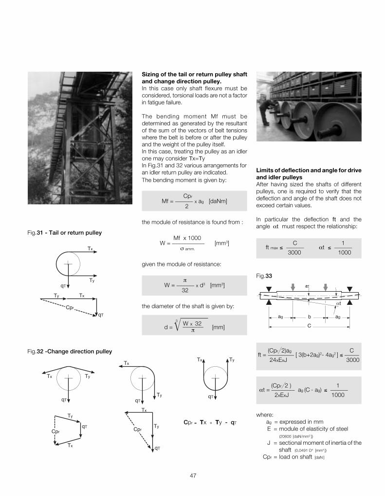
Sizing of the tail or return pulley shaftand change direction pulley.In this case only shaft flexure must beconsidered, torsional loads are not a factorin fatigue failure.
The bending moment Mf must bedetermined as generated by the resultantof the sum of the vectors of belt tensionswhere the belt is before or after the pulleyand the weight of the pulley itself.In this case, treating the pulley as an idlerone may consider Tx=TyIn Fig.31 and 32 various arrangements foran idler return pulley are indicated. Limits of deflection and angle for drive
and idler pulleysAfter having sized the shafts of differentpulleys, one is required to verify that thedeflection and angle of the shaft does notexceed certain values.
In particular the deflection ft and theangle αt must respect the relationship:
C 1
ft max ≤ ______ αt ≤ ______
3000 1000
Cpr = Tx + Ty - qT
Tx
Ty
qTCpr
Tx
CprTy
qT
Tx Ty
qTqT
Tx
Ty
Ty
qT
Tx
Tx
TyqT
Cpr
qT
Ty Tx
Fig.31 - Tail or return pulley
Fig.32 -Change direction pulley
where: ag = expressed in mm
E = module of elasticity of steel(20600 [daN/mm2 ])
J = sectional moment of inertia of the shaft (0,0491 D4 [mm4 ])
Cpr = load on shaft [daN ]
(Cpr 2)ag C
ft = _________ [ 3(b+2ag)2- 4ag2 ] ≤ _____
24xExJ 3000
(Cpr 2 ) 1 αt = ________ ag (C - ag) ≤ ______
2xExJ 1000
αt
C
ag agb
ft
Fig.33

48
TechnicalInformationproject and design criteriafor belt conveyors
1
®
1.6 - Rollers, function and designcriteria
In a conveyor, the elastomer belt representsthe most perishable and costly item. Therollers that support the belt along its lengthare no less important, and therefore theyshould be designed, chosen andmanufactured to optimise their working lifeand that of the belt itself.
The resistance to start up and rotation ofrollers has a great influence on the belt andin consequence to the necessary power tomove the belt and keep it moving.
The body of the roller and that of its endcaps, the bearing position and itsaccompanying system of protection, are theprincipal elements which impact the life andtorque characteristics of the roller.
Refer to chapter 2 where the constructioncriteria of rollers for belt conveyors arepresented along with the factors which mustbe taken into account for a correct projectdesign.
In the following sections we should examineother factors such as the :
• balance and start up resistance;• tolerances;• type of roller shell; characteristics of the tube and thickness - the fitting of the end caps;• frictional resistance and impact resistan- ce;
•type of bearing- protection system- fit to the spindle and end caps- lubrication- alignment;
•spindle : characteristics and manufactur- ing tolerances.
Fig. 34

49
1.6.1 - Choice of roller diameter inrelation to speed
We have already stated that one of theimportant factors in the design of aconveyor is the speed of the belt movementin relation to the load conditions required.
From the belt speed and roller diameter weare able to determine the revolutions perminute of the roller using the formula :
v x 1000 x 60 n = ———————— [r.p.m]
D x πwhere: D = roller diameter [mm] v = belt speed [m/s]
Tab.15 gives the existing relationshipbetween maximum belt speed, roller dia-meter and the relative r.p.m.
In choosing the roller it is interesting to notethat even if a roller of larger diameter exhibitsa higher inertia on start up, it actually yields,other conditions being equal, manyadvantages such as : less revolutions perminute, less wear of bearings and housing,less rolling friction and reduced wearbetween the roller and the belt.
50
63
76
89
102
108
133
159
194
Tab. 15 - Maximum speed and numbersof roller revolutions
Roller Belt r.p.m.diameter speedmm m/s n
573
606
628
644
655
707
718
720
689
1.5
2.0
2.5
3.0
3.5
4.0
5.0
6.0
7.0
The correct choice of diameter must takeinto consideration the belt width. Tab.16shows the diameter of rollers in relation tobelt width.
One may have indicated more diameters where the choice will be made in relation to the material lump size and theseverity of working conditions.
Belt For speedwidth ≤ 2 m/s 2 ÷ 4 m/s ≥ 4 m/smm Ø roller mm Ø roller mm Ø roller mm
500 89 89
650 89 89 108
800 89 108 89 108 133 133
1000 108 133 108 133 133 159
1200 108 133 108 133 159 133 159
1400 133 159 133 159 133 159
1600 133 159 133 159 194 133 159 194
1800 159 159 194 159 194
2000 159 194 159 194 159 194
2200 e oltre 194 194 194
Tab.16 - Roller diameter advised

50
TechnicalInformationproject and design criteriafor belt conveyors
1
®
Principal relevant factors:
Iv = belt load t/hv = belt speed m/sao = pitch of the troughing sets upper strand mau = pitch of the return roller set mqb = weight of belt per linear metre Kg/mFp = participation factor of roller under greatest stress seeTab.17
(depends on the angle of the roller in the transom )Fd = impact factor see Tab.20 (depends on the material lump size)
Fs = service factor see Tab.18Fm = environment factor seeTab.19Fv = speed factor see Tab. 21
1.6.2 - Choice in relation to load
The type and dimensions of rollers used inbelt conveyors depends mainly on the widthof the belt itself, the pitch of the troughingsets, and above all, the maximum load onthe rollers most under pressure, notwithstanding other correction factors.
The calculation of load forces is normallymade by the project designer of the plant.Nevertheless, as a check or in the case ofsimple conveyors, we present the followingconcepts for determining the facts.
The first value to define is the load on thetroughing sets. Following this, dependingon the type of troughing set (carrying, returnor impact), the number of rollers in atransom or frame, the angles of the side
roller, the material lump size and otherrelevant factors as listed below. One is ableto calculate the roller load with the maximumforce for each type of troughing set.
Furthermore there are some correctionfactors keeping count of the plant workinghours per day (service factor), of the envi-romental conditions and of the speed forthe different diameters of the rollers.
The load value obtained in this way may becompared with the load capacity of therollers indicated in this catalogue valid for aproject l ife of 30.000 hours. For atheoretically different life, the load capacitymay be multiplied by a coefficient reportedon Tab.22 corresponding to life required.
Tab. 17 - Participation factor Fp
0° 20° 20° 30° 35° 45°
1,00 0.50 0.60 0.65 0.67 0.72

51
Tab. 21 - Speed factor Fv
Belt speed Roller diameter mm
m/s 60 76 89-90 102 108-110 133-140 159
0.5 0.81 0.80 0.80 0.80 0.80 0.80 0.80
1.0 0.92 0.87 0.85 0.83 0.82 0.80 0.80
1.5 0.99 0.99 0.92 0.89 0.88 0.85 0.82
2.0 1.05 1.00 0.96 0.95 0.94 0.90 0.86
2.5 1.01 0.98 0.97 0.93 0.91
3.0 1.05 1.03 1.01 0.96 0.92
3.5 1.04 1.00 0.96
4.0 1.07 1.03 0.99
4.5 1.14 1.05 1.02
5.0 1.17 1.08 1.0
Tab. 22 - Coefficient of theoretical life of bearing
Theoretic project life of bearing 10'000 20'000 30'000 40'000 50'000 100'000
Coefficient with base 30'000 hours 1.440 1.145 1.000 0.909 0.843 0.670
Coefficient with base 10'000 hours 1 0.79 0.69 0.63 --- ---
Tab. 20 - Impact factor Fd
Material lump Belt speed m/ssize 2 2.5 3 3.5 4 5 6
0 ÷ 100 mm 1 1 1 1 1 1 1
100 ÷ 150 mm 1.02 1.03 1.05 1.07 1.09 1.13 1.18
150 ÷ 300 mm 1.04 1.06 1.09 1.12 1.16 1.24 1.33in layers of fine material
150 ÷ 300 mm 1.06 1.09 1.12 1.16 1.21 1.35 1.5without layers of fine material
300 ÷ 450 mm 1.2 1.32 1.5 1.7 1.9 2.3 2.8
Tab. 18 - Service factor
Life Fs
Less than 6 hours per day 0.8
From 6 to 9 hours per day 1.0
From 10 to 16 hours per day 1.1
Over 16 hours per day 1.2
Tab. 19 - Environment factor
Conditions Fm
Clean and regular 0.9maintenance
Abrasive or corrosive material 1.0present
Very abrasive or corrosive 1.1material present
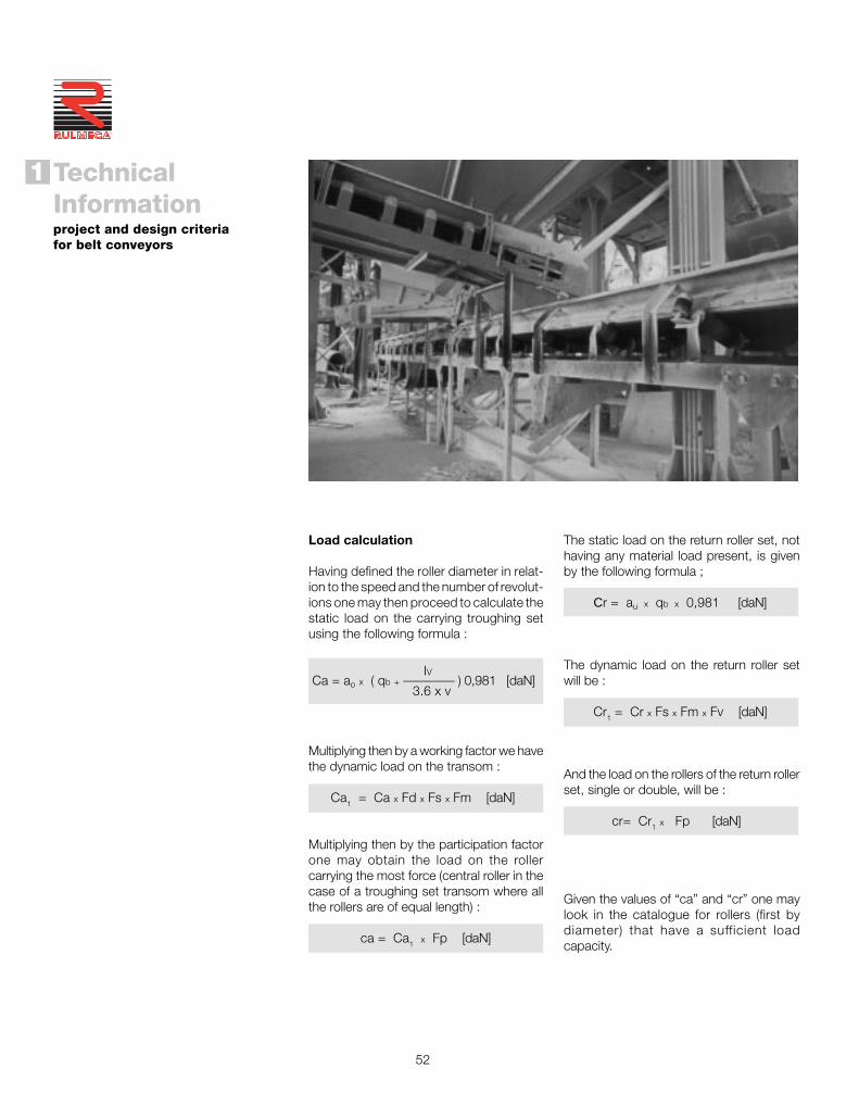
52
TechnicalInformationproject and design criteriafor belt conveyors
1
®
The static load on the return roller set, nothaving any material load present, is givenby the following formula ;
Cr = au x qb x 0,981 [daN]
The dynamic load on the return roller setwill be :
Cr1 = Cr x Fs x Fm x Fv [daN]
And the load on the rollers of the return rollerset, single or double, will be :
cr= Cr1 x Fp [daN]
Given the values of “ca” and “cr” one maylook in the catalogue for rollers (first bydiameter) that have a sufficient loadcapacity.
Load calculation
Having defined the roller diameter in relat-ion to the speed and the number of revolut-ions one may then proceed to calculate thestatic load on the carrying troughing setusing the following formula :
IV Ca = ao x ( qb + ———— ) 0,981 [daN]
3.6 x v
Multiplying then by a working factor we havethe dynamic load on the transom :
Ca1 = Ca x Fd x Fs x Fm [daN]
Multiplying then by the participation factorone may obtain the load on the rollercarrying the most force (central roller in thecase of a troughing set transom where allthe rollers are of equal length) :
ca = Ca1 x Fp [daN]

53
1.7 - Loading of belt and impact rollers
The feed system of material falling ordropping onto a belt conveyor must beconstructed to minimise or eliminate impactdamage to the belt material and surface.This is of particular importance when thematerial falls from a considerable height andconsists of large lumps with sharp edges.The rollers supporting or carrying the beltin the loading zone are normally installedas impact design (with rubber rings),mounted onto troughing set frames setclose to each other. In this way the belt issupported in a flexible manner.
It is a widely held view that the use ofsuspension sets of the “garland” design-Fig.37-38, thanks to their intrinsic flexiblecharacteristics absorb with great efficiencythe impact of materials falling onto the beltand, what is more, the “garland” is able toadapt to conform to the shape of thecharge (or load).
Fig.35
Fig.36
Fig.37
Fig.38

54
TechnicalInformationproject and design criteriafor belt conveyors
1
®
Please refer to chapter 3 of this cataloguefor greater detail regarding the programmeof the design of impact rollers with rubberrings of high shock absorbing qualities andfor the programme of suspension sets as“garland” design.
1.7.1 - Calculation of associated for-ces on impact rollers
The definition of the correct load fall heightHc may be given by the folowing formula :
Hc = Hf + Hv x sen2 γ
where: Hf = fall height from the upper face of
the loading belt to the contact point of material contained in the hopper ;
Hv = height from the contact point of material contained in the hopper to the belt face of the lower belt ;
γ = hopper inclination angle.
In the choice of impact rollers we proposeto follow two significant design aspects :
- constant loading with uniform fine material
- loading with material consisting of largelumps.
Particular attention must be paid at theproject stage to the feed system and to thedesign of impact troughing sets.
The project designer of the conveyor systemmust take into account that :
- the impact of material onto the belt musttake place in the conveyor direction and ata speed that approximates to the speed ofthe belt.
- the loading hopper is positioned so thatmaterial falling from it is deposited as nearas possible to the centre of the belt.
Fig.39
- the height that the material falls must bereduced to the minimum possible,compatible with the requirements of theplant design.
γ
Hv
Hf
NO
Fig.40
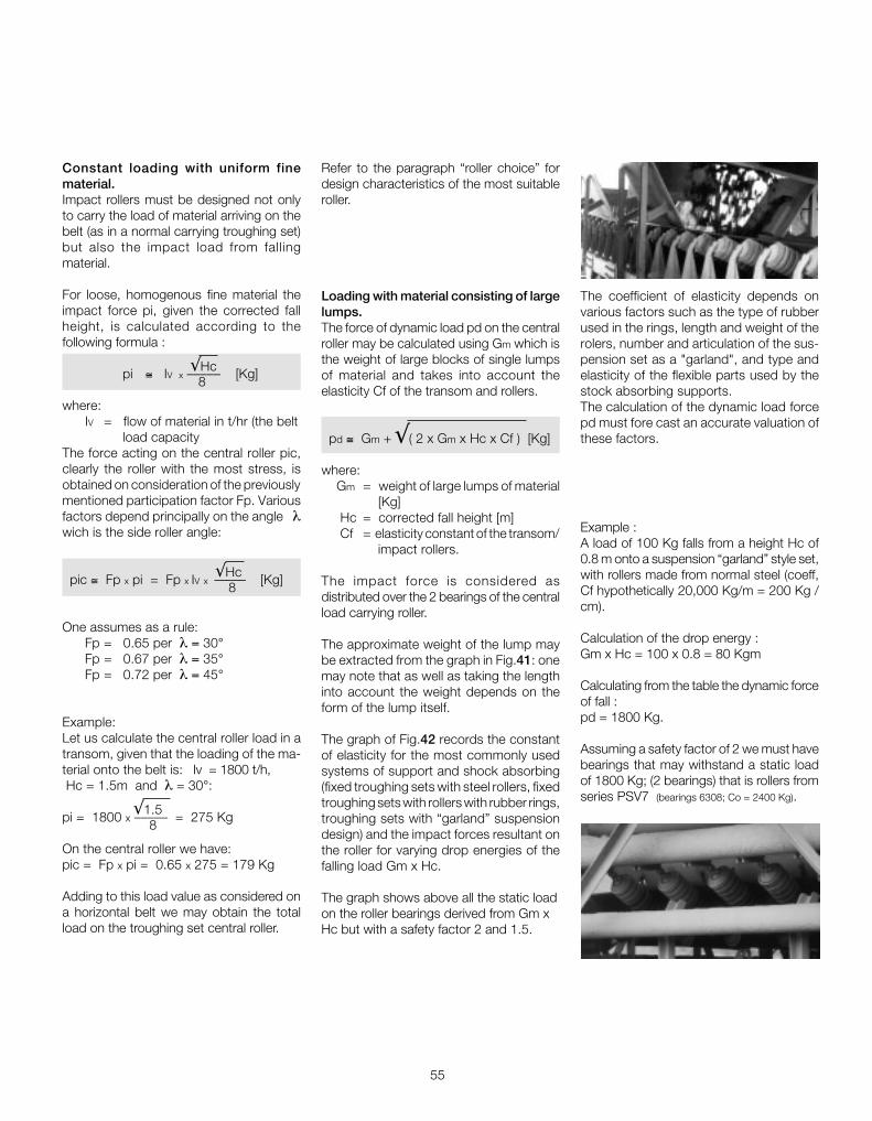
55
Constant loading with uniform finematerial.Impact rollers must be designed not onlyto carry the load of material arriving on thebelt (as in a normal carrying troughing set)but also the impact load from fallingmaterial.
For loose, homogenous fine material theimpact force pi, given the corrected fallheight, is calculated according to thefollowing formula :
√Hc pi ≅ IV x ––––– [Kg]
8
where: IV = flow of material in t/hr (the belt
load capacityThe force acting on the central roller pic,clearly the roller with the most stress, isobtained on consideration of the previouslymentioned participation factor Fp. Variousfactors depend principally on the angle λwich is the side roller angle:
√Hc pic ≅ Fp x pi = Fp x IV x ––––– [Kg]8
One assumes as a rule: Fp = 0.65 per λ = 30° Fp = 0.67 per λ = 35° Fp = 0.72 per λ = 45°
Example:Let us calculate the central roller load in atransom, given that the loading of the ma-terial onto the belt is: Iv = 1800 t/h, Hc = 1.5m and λ = 30°:
√1.5pi = 1800 x ––––– = 275 Kg 8
On the central roller we have:pic = Fp x pi = 0.65 x 275 = 179 Kg
Adding to this load value as considered ona horizontal belt we may obtain the totalload on the troughing set central roller.
Example :A load of 100 Kg falls from a height Hc of0.8 m onto a suspension “garland” style set,with rollers made from normal steel (coeff,Cf hypothetically 20,000 Kg/m = 200 Kg /cm).
Calculation of the drop energy :Gm x Hc = 100 x 0.8 = 80 Kgm
Calculating from the table the dynamic forceof fall :pd = 1800 Kg.
Assuming a safety factor of 2 we must havebearings that may withstand a static loadof 1800 Kg; (2 bearings) that is rollers fromseries PSV7 (bearings 6308; Co = 2400 Kg).
Loading with material consisting of largelumps.The force of dynamic load pd on the centralroller may be calculated using Gm which isthe weight of large blocks of single lumpsof material and takes into account theelasticity Cf of the transom and rollers.
pd ≅ Gm + √( 2 x Gm x Hc x Cf ) [Kg]
where: Gm = weight of large lumps of material
[Kg] Hc = corrected fall height [m] Cf = elasticity constant of the transom/
impact rollers.
The impact force is considered asdistributed over the 2 bearings of the centralload carrying roller.
The approximate weight of the lump maybe extracted from the graph in Fig.41: onemay note that as well as taking the lengthinto account the weight depends on theform of the lump itself.
The graph of Fig.42 records the constantof elasticity for the most commonly usedsystems of support and shock absorbing(fixed troughing sets with steel rollers, fixedtroughing sets with rollers with rubber rings,troughing sets with “garland” suspensiondesign) and the impact forces resultant onthe roller for varying drop energies of thefalling load Gm x Hc.
The graph shows above all the static loadon the roller bearings derived from Gm xHc but with a safety factor 2 and 1.5.
Refer to the paragraph “roller choice” fordesign characteristics of the most suitableroller.
The coefficient of elasticity depends onvarious factors such as the type of rubberused in the rings, length and weight of therolers, number and articulation of the sus-pension set as a "garland", and type andelasticity of the flexible parts used by thestock absorbing supports.The calculation of the dynamic load forcepd must fore cast an accurate valuation ofthese factors.

56
TechnicalInformationproject and design criteriafor belt conveyors
1
®
6090 4030
80
90100
200
5070
60
70
8090
100
4050
60
70100
500
600
800900
1400
1000
400
700
800
900
400
500
600
300
200
300
400
300
400
500
600
700 300
200
200
100
8090
Specific weight
1.223
2
2
3
4
5
3
2
1
6
7
8
9
9
10 4
5
6
4
5
6
7
83
20
20
30
89
10
869
710
1057
30
40
50
50
60
70
80
20
2030
40
0.8
1
3
4
2
600 800 10000
Wie
gh
t "
Gm
" o
f a
lum
p o
f m
ater
ial (
kg)
400200
Dimensions of lump" Lb " ( mm )
Lb
Fig.41 - Weight of lump of material

57
Fig.42 - Constant of elasticity Cf
5000-
4200
4400
4600
4800
200
400
600
800
1200
1400
1600
1800
2200
2400
2600
2800
3200
3400
3600
3800
1000-
2000-
3000-
4000-
coefficient security
00
2 84 6 10 20 40060 8040 100 2003 5 7 15 30 150
= 1.5= 2
300 800600 1000
-
-
-
--
-
-
-
-
-
-
-
--
-
-
-
-
-
-
--
-
-
- 200
- 800
- 400
- 600
- 200
- 400
- 600
- 800
-
--1000
--1000-
-
-
-
-
-
-
-
-
-
-
-
-
-
-
-
-
-
-
-
-
-
-
-
-
-
--2000
--3000
--4000
--5000
--3000
--3800
--2000
-
-
-
-
-
-
-
-
-
-
-
-
-
-
-
-
-
-
-
-
Drop energy = Gm x Hc (kg.m)
Be
ari
ng
sta
tic
lo
ad
C
o
(kg
)
Dy
na
mic
fa
llin
g f
orc
e
Pd
(k
g)
Cf=
1000
kg/
cm
Cf = Costant of elasticity
Cf=
100
kg/c
m
Cf=
150
kg/c
m
Cf=
200
kg/c
m
Steel rolle
r
Roller with
rings
Garland
withfiv
ero
llers
Garland with
shoc
k
abso
rber
s

58
TechnicalInformationproject and design criteriafor belt conveyors
1
®
1.8 - Other accessories
Amongst all of other conveyor components,the belt cleaning system and covers areregarded in certain situations, of fund-amental importance and must be consider-ed at an early stage in the project design ofthe conveyor itself.
1.8.1 - Belt cleaners
Savings in utilising efficient systems of beltcleaning may be amply demonstrated, inparticular resulting from a reduction in beltmaintenance time and increased product-ion, proportional to the quantity of materialrecovered in the process and a largeincrease in the life of moving parts.
The static systems that are utilised themost are the most diverse as they may beapplied along all positions on the dirty sideof the belt. They are acting directly on thebelt using a segmented blade. Fig. 44
Fig.43 - Ideal positions for the installation of cleaning devices
43
1 2
3 on internal side of belt on the return section and before the snub pulleys or directional change pulley.4 on internal side of belt before the return pulley.
1 on drive pulley
2 at about 200mm after the tangential point where belt leaves pulley
Fig.44
There are a variety of devices used for beltcleaning. The majority of these may bedivided into two groups : static anddynamic.

59
1.8.2 - Belt inversionOn return sections of the belt on very longconveyors, the belt is turned over 180° toreduce the phenomena of adhesion ofmaterial residue on the rollers and on thecross member of the troughing sets. Thereturn strand of the belt may be turned over180° after the drive drum and subsequentlyturned to its original position before thereturn drum.
Turning the belt over is generally effectedby means of a series of rollers orientated asrequired. The minimum length to turn overa belt is generally about 14/22 times itswidth..
The rollers on the return set, thanks to thisdevice, are no longer in contact with thecarrying upper strand of the belt which isencrusted with material residue.
1.8.3 - Belt conveyor covers
After having defined the components ofprimary importance the project designerconsiders secondary accessories, such ascovers.
The necessity to protect the belt conveyoris dictated by the climate, the characteristicsof the conveyed material ( dry, light,“volatile”) and the type of plant.
Fig.45
Fig.46
The dynamic systems where motors areused are of less variety and more costly interms of capital cost, installation andcommissioning.
They consist of pulleys or motorisedpulleys on which are assembled or fixedspecial brushes, that are then in directcontact with the belt. Fig.45
Other cleaners are those of plough ordeviator design that are applied to theinside strand of the belt return section.
They are used to remove material deposit-ed before the drive and return pulleys orcertain other points where the materialmay become trapped between the pulleyand belt, affecting the orderly tracking ofthe belt. Fig.46.
Dirty sideClean side
Dirty sideClean side
Fig.47

60
TechnicalInformationproject and design criteriafor belt conveyors
1
®
To obtain the result one must calculatethe volumetric load IVT ( for the speedv = 1m/s ) given the inclination of theconveyor δ = 6°.
IM IVT = ————— [m3/h]
v x K x K1
in which: IM = volumetric load
v = belt speed
K = crrection coefficient to suit theinclination 6°: 0,98 (diagram Fig 8 pag.31).
K1 = correction coefficient to suit the feedirregularity : 0,90 (pag.31)
Speed and belt widthFrom Tab. 3 (pag.23) we are able to definethat the said material may be grouped intoB and given that the lump size is 80/150mm the maximum advised speed resultsas 2,3 m/s.
From Tab. 5 (pag.26-30) we may evaluatewhich type and design of carrying troughingsets are needed, given the speed just found,that satisfies the volumetric load IM requiredas 833 m3/h.
1.9 - Project examples of a belt con-veyor
To clarify our presentation of critical tensionsin various sections of the belt conveyor hereis a project example.The relative data concerning the conveyedmaterial and its physical / chemicalcharacteristics are as follows :
Material:- clinker of cement (Tab. 2 pag.20)- specific weight: 1.2 t/m3
- lump size 80 to 150 mm- abrasiveness: very abrasive- angle of friction natural or at rest : ~ 30°
Required load:IV = 1000 t/h corresponding to the volumetric loadIM = 833 m3/h
Plant characteristics :- centres 150 m- change of height H = + 15 m (rising)- inclination = 6°~- working conditions : standard- utilisation : 12 hours per day
From the data supplied we are able tocalculate :speed, belt width, design and type ofconveyor troughing sets.
Furthermore we may define : the belttensions in various critical areas and fromthese the absorbed power and the belttype.

61
- for the return rollers the static load will be:
Cr = au x qb x 0,981 [daN]
Cr= 3 x 9,9 x 0,981 = 29,2
the dynamic load will be:
Cr1 = Cr x Fs x Fm x Fv [daN]
Cr1= 29,2 x 1,1 x 1 x 0,97 = 31,2
where: Fv = 0,97 speed factor (it has been considered
that relative to 2,5 m/s see Tab. 21, pag.51)
choosing the return troughing set with plainroller the load on the return roller will be :
cr = Cr1 x Fp [daN]
cr= 31,2 x 1 = 31,2
where from Tab. 17 the participation factorwith return plain roller set Fp = 1
We are able therefore to choose a belt1000 mm, the rollers for carring and returnidlers both of loaded and return belt (seeChapter 2)
- rollers for carrying idlers type PSV/1, ø108 mm, with bearings 6204 of lengthC = 388 mm with load capacity 148 Kgthat satisfies the required loading of113,2 Kg ,
- return roller type PSV/1, ø108 mm , withbearings 6204, length C=1158 mm withload capacity 101 Kg that satisfies therequired loading of 31,2 Kg.
the load on the central roller of a carryingtroughing set is given by :
ca = Ca1 x Fp [daN]
ca = 174,2 x 0,65 = 113,2
where from Tab. 17 pag.50 the particip-ation factor of a troughing set 30° Fp = 0,65
Roller choiceIn Tab. 16 pag.49 with a belt of 1000 mmand a speed of 2.3 m/s we may chooserollers with diameter 108 mm.
We may now proceed to determine the loadfalling on the roller in the carrying strand andthose of the return strand.
Assuming we may use a belt with aresistance class equal to 315 N/mm, withcover thickness 4+2, and with a value qb
of 9,9 kg/m, we have:
- for carrying rollers the static load will be:
IVCa = ao x ( qb + ———— )x 0,981 [daN] 3,6 x v
1000Ca =1,2( 9,9+ ———— ) 0,981 = 153,8
3,6 x 2,3
the dynamic load will be:
Ca1 = Ca x Fd x Fs x Fm [daN]
Ca1 = 153,8 x 1,03 x 1,1 x 1 = 174,2
where: Fd = 1,03 from table 20 , pag.51
Fs = 1,10 from table18 , pag.51
Fm = 1 from table 19 , pag.51
Troughing set pitchThe pitch may be chosen as a function ofthe deflection of the belt between two con-secutive troughing sets.
Tab. 6 pag.34 shows how to determinethe maximum pitch of troughing sets, as afunction of the belt width and the specificweight of the conveyed material.
We need to verify that the deflection doesnot supersede 2% of the pitch.
A greater deflection may give rise to materialmass deformation during the beltmovement, and consequently elevatedfriction.
Then we would be able to determine a majorfactor: that is major power absorption,giving rise to unusual stresses whether onthe rollers or in the belt over and above thepremature wear in the cover of the belt.
In our example, given that the belt width is1000 mm with specific weight of materialof 1.2 t/m3 the tables indicate that :
- for the carrying troughing sets the advisedpitch is that of 1.2 m
- for the return sets the advised pitch is thatof 3.0 m.
Substituting we have: 833
IVT = ————————— = 410 m3/h 2,3 x 0,98 x 0,90
Given the angle of repose of the material inquestion is about 30° from Tab. 1 pag.19we may deduce that the angle of surchargewould be established in the order of 20°.
Having chosen a carrying troughing set witha transom side roller angle of λ = 30°, thebelt width that meets the load requirementIVT of 410 m3/h at 1 m/s is 1000 mm.

62
TechnicalInformationproject and design criteriafor belt conveyors
1
®
Tangential force and absorbed powerWe may now determine the total tangential force Fu at the drum periphery extractingthe values qRO , qRU and qG.
given:D = 108 roller diameterf = 0,017 friction coefficient inside material and of the rotating parts (Tab. 9 pag.38)
Cq = 1,5 fixed coefficient of resistance (Tab. 7 pag.38)qb = 9,9 Kg/m ( utilising a belt resistance class 315 N/mm with a cover thickness 4+2 Tab. 10 pag.39 )Ct = 1 coefficient of passive resistance given by the temperature
(per qRO - qRU vedi Tab.11 pag.39 )
weight of rotating parts upper troughing set
17,8qRO = ————————————— = ——— = 14,8 Kg/m pitch of upper sets 1,2
weight of rotating parts
lower troughing set 13,3qRU = ————————————— = ——— = 4,4 Kg/m pitch of upper sets 3,0
IV
1000qG = ———— = ————— = 120,8 Kg/m 3,6 x v 3,6 x 2,3
The total tangential force Fu is given by the algebraic sum of the tangential forces Fa andFr relative to upper and lower sections of belt for which:
Fu = Fa + Fr [daN]
Fa = [ L x Cq x f x Ct ( qb + qG + qRO ) + H x ( qG + qb ) ] x 0,981 [daN]Fa = [150x1,5x 0,017x 1 (9,9+120,8+14,8)+15 x (120,8+9,9)]x 0,981 = 2469
Fr = [ L x Cq x f x Ct ( qb + qRU ) - ( H x qb ) ] x 0,981 [daN]Fr = [150 x 1,5 x 0,025 x 1 (9,9 + 4,4) - (15 x 9,9)] x 0,981 = - 92
Fu = Fa + Fr = 2469 + ( - 92 ) = 2377 .
We consider an efficiency of the reduction gear and of possible transmissions as η = 0,86will be :
Fu x v 2377 x 2,3 P = ———— [ kW ] = ——————— ≅ 64 kW 100 x η 100 x 0,86

63
Tensions T1 - T2 - T3 - To -TgLet us propose to design a conveyor drivenby a single driving pulley, rubber coveredand positioned at the head, given that thesnub pulleys are positioned to give a wrapangle of 200°; a tension device withcounterweight positioned at the tail.
From Tab. 12 pag. 41 one may determinethe wrap factor Cw = 0,42.
The tension downstream from the drivepulley is given by :
T2 = Fu x Cw [daN]
T2 = 2377 x 0,42 = 998
The maximum tension upstream of the drivepulley will be :
T1 = Fu + T2 [daN]
T1 = 2377 + 998 = 3375
While the tension downstream of the returnpulley is :
T3 = T2 + Fr [daN]
T3 = 998 - 92 = 906
To derive the maximum deflection betweentwo consecutive carrying troughing setsequal to 2% we must apply the followingformula :
T0 = 6,25 ( qb + qG ) x a0 x 0,981 [daN]
T0 = 6.25 x (120,8 + 9,9) x1,2 x 0,981 = 961
The tension T3 is lower than the T0 there-fore we have to provide a counterweightdimensioned to obtain the tension T0.We have therefore to assume T3=T0 andwe have to recalculate consequently thetensions T2 and T1 that result:
T2 = 1053 daNT3 = 3430 daN
One may now determine the tension “Tg”in the belt at the tension unit connectionpoint.The plant project data has foreseen acounterweight tension unit positioned at theconveyor tail end.The counterweight load Tg necessary tomaintain the system in equilibrium is givenby :
Tg = 2 x T3 [daN]
Tg = 2 x 961 = 1922
Belt choiceGiven the maximum working tension of theconveyor: T1 = 3375 daN .
The unitary working tension of the beltfor mm of width is given by:
T max x 10 Tu max = ———––—–– [N/mm] N
3430 x 10 Tu max = ————— = 34,3 N/mm
1000
The breaking load of the belt will correspondwith the working load multiplied by asecurity factor “8” for belts with steelinserts and “10” for belts with textile inserts.In our case we may proceed to choose abelt with resistance equal to 400 N/mm.
Because this belt resistance is higher thanthe one selected in the starting data of thiscalculation, (315 N/mm), the belt weight ishigher and we have to recalculate theT1 and T2 accordingly.
The resulted tensions are anyway lowerthan T1 and T2 above, therefore the follow-ing calculations will be made using
T2 = 1053 daNT3 = 3430 daN

64
TechnicalInformationproject and design criteriafor belt conveyors
1
®
Diameter of drive pulley shaftLet us utilise a motor gearbox to drive the conveyor in question.
Drive pulley data:D = 400 mm diameter (as Tab.13)
qT = 220 daN weight of pulleyn = 110 rpmag = 0,180 m distance between the supports and pulley flange
Let us determine the resultant Cp of the tensions and the pulley weight (for simplicity letus suppose T and qT perpendicular between them)
Cp = �( T1 + T2 )2 + qT 2 [daN] = �( 3430 +1053 )2 + 220 2 = 4488 daN
The bending moment will be : Cp 4488 Mf = ———— x ag [daNm] = ––––––– x 0,180 = 404 daNm 2 2
The torsional moment will be : P 64 Mt = ——— x 954,9 [daNm] = ––––––– x 954,9 = 555,6 daNm n 110
One may now determine the ideal bendingmoment :
Mif = � Mf 2+ 0,75 x Mt2 [daNm] = �404 2+ 0,75 x 555,6
2 = 629 daNm
Consequently we derive the value of the module of resistance W given that σamm 7,82 daN/mm2 for heat treated steel C40
Mif x1000 629 x 1000 W = —————— [mm3] = ––––––––––– = 80435 mm3
σamm 7,82
from which we may find the diameter of the pulley motor shaft :
3 W X 32 3 80435 X 32
d = �———––– mm = �————–––—– ≅ 93 mm π 3,14
The drum shaft diameter on the bearing seats, will be made according the above formula,or the nearer larger diameter available on the bearing.The shaft diameter inside the hub and/or inside the drum (normally the raw shaft diameter)is determined with the formulas described in the paragraph " Limits of deflection and anglefor motor and idler pulleys " at pag.47 and in this case the raw shaft diameter results120 mm.

65
Diameter of return pulley shaft
Non-drive pulley data : D = 315 mm diameter (as Tab.13)
qR = 170 daN pulley weight ag = 0,180 m distance between the support and pulley flange
Let us determine the resultant Cpr of the tensions and the pulley weight (for simplicity letus suppose T3 and qT is perpendicular between them)
Cpr = �( 2T3 )2 + qT 2 [daN] = �( 2 x 961 )2 + 170 2 = 1930 daN
The bending moment will be : Cpr 1930 Mf = ———— x ag [daNm] = ––––––– x 0,180 = 174 daNm 2 2
Consequently we derive the value of the module of resistance W given thatσamm 7,82 daN/mm2 for heat treated steel C40
Mif x1000 174 x 1000 W = ————— [mm3] = ––––––––––—– = 22250 mm3
σamm 7,82
from which we may find the diameter of pulley motor shaft :
3 W X 32 3 22250 X 32
d = �———––– mm = �————–––– ≅ 61 mm π 3,14
The drum shaft diameter on the bearingseats, will be made according the aboveformula, or the nearer larger diameter avai-lable on the bearing.The shaft diameter inside the hub and/orinside the drum (normally the raw shaftdiameter) is determined with the formulasdescribed in the paragraph " Limits ofdeflection and angle for motor and idlerpulleys " at pag.47 and in this case theraw shaft diameter results 95 mm.
66
TechnicalInformationproject and design criteriafor belt conveyors
1
®
ConclusionsUsing successive steps we have obtainedfrom the data of the relative characteristicsof the belt conveyor components thefollowing summary :
- the speed of the conveyed material is v = 2,3 m/s
- carrying troughing sets with side rollersat λ = 30°
- return sets with plain roller
- belt width 1000 mm with breaking load 400 N/mm
- carrying troughing set pitch 1,2 m
- lower return sets pitch 3 m
- load roller in carrying troughing setseries PSV/1 Ø 108 mm C=388 mm
- return rollersseries PSV/1 Ø 108 mm C=1158 mm
- power needed to move the belt con-veyor 64 kW
- belt deflection between twoadjacent troughing sets < 2%
- drive pulleyD = 400 mm, Ø shaft 100 mm
- return pulleyD = 315 mm, Ø shaft 65 mm
One may consider the use of a traditionaldrive arrangement (drive pulley + gearbox +transmission gearing) or a motorised pulley.
In the later case, a pulley motor may bechosen using the relevant catalogue. ThetypeTM801 of 75 kW with a shaft of 120mm diameter meets the specification.

67
2 Rollers