1 time-reversal massive multipath effect: a single-antenna...
TRANSCRIPT

1
Time-Reversal Massive Multipath Effect: A
Single-Antenna “Massive MIMO” Solution
Yi Han, Yan Chen, Beibei Wang, and K. J. Ray Liu
Origin Wireless Inc., College Park, MD 20742, USA
ECE Dept., University of Maryland, College Park, MD 20742, USA
Email: {yhan1990, yan, bebewang and kjrliu}@umd.edu
Abstract
The explosion of mobile data traffic calls for new efficient 5G technologies beyond what current 4G
LTE can provide. Massive MIMO, which has shown the great potential in improving the achievable rate
with a very large number of antennas, becomes a popular candidate. However, several critical challenges
in designing the analog front-end and coordinating the large-scale antenna array have to be carefully
addressed before the massive MIMO can be actually adopted. Therefore, a natural question to ask is:
does there exist a good alternative that can achieve similar system performance to massive MIMO with
a simpler design? In this paper, we show that by using time-reversal approach, with a sufficiently large
bandwidth, one can harvest massive multipath naturally existing in the environment to form high number
of virtual antennas to achieve the desired massive MIMO effect with a single antenna. We answer the
above question by analyzing the time-reversal massive multipath effect (TRMME) and the achievable
rate with different signature waveforms. We also derive the corresponding asymptotic achievable rate
under a massive multipath setting. Experiment result based on real channel measurements shows the
approach to realize the massive multipaths in practical environment. Moreover, based on our experiment
with real indoor measurement, even with only a single antenna, the time-reversal wideband system can
achieve comparable performance as the massive MIMO system in terms of expected achievable rate.
Index Terms
Massive MIMO, time-reversal (TR), time-reversal division multiple access (TRDMA), time-reversal
massive multipath effect (TRMME), expected achievable rate
November 24, 2015 DRAFT

2
I. INTRODUCTION
While the past few decades has witnessed the monumental success of mobile and wireless ac-
cess to the Internet, the proliferation of new mobile communication devices, such as smartphones
and tablets, has in turn led to an exponential growth in network traffic. According to the most
recent Cisco Visual Networking Index (VNI) annual report [1], the global mobile data traffic grew
69% and the number of mobile devices increased almost half a billion (497 million) in 2014.
It is also predicted in the report that the global mobile data traffic will increase nearly tenfold
between 2014 and 2019. The demand for supporting the fast-growing consumer data rates urges
the wireless service providers and researchers to seek a new efficient radio access technology,
which is the so-called 5G technology, beyond what current 4G LTE can provide. Besides ultra-
densification and mmWave, massive multiple-input multiple-output (MIMO) is one of “big three”
5G technology [2], which can offer multi-fold benefits such as enormous enhancement in spectral
efficiency and power efficiency [3] and simple transmit/receiver structures due to the quasi-
orthogonal nature [4]. These benefits make massive MIMO one of the five disruptive technology
directions for 5G communication [5].
Even though the benefits of massive MIMO seem very promising, several critical challenges
must first be addressed before it can be implemented in practice. First of all, a challenging task
is the analog front-end design [6], for example, each tiny antenna need its own power amplifier
and analog-to-digital convertor (ADC). Moreover, the antenna correlation and mutual coupling
due to the increasing number of antennas has to be carefully addressed as well [7] [8]. The
researchers in Lund University built a 100-antenna MIMO testbed, and the size is 0.8× 1.2× 1
m with 300kg weight and 2.5kW average power consumption [9]. Considering the challenges
of massive MIMO in hardware design and coordinating the large scale antenna array, a natural
question to ask is: does there exist a good alternative that can achieve similar system performance
to massive MIMO with a simpler implementation? The answer is yes and the time-reversal (TR)
technology is potentially a counterpart of massive MIMO in 5G communications.
The straightforward approach to realize the massive MIMO effect is through utilizing an
excessive amount of physical antennas as the current massive MIMO systems. On the other
hand, it is well known that radio signals will experience many multipaths due to the reflection
from various scatters, especially in indoor environment. TR’s focusing effect is in essence a
November 24, 2015 DRAFT

3
(a) An illustration of massive MIMO system (b) An illustration of TR system
Fig. 1: Comparison between massive MIMO system and TR system
spatial-temporal resonance effect that brings all the multipaths to arrive at a particular location
at a specific moment. Such a phenomenon will allow us to utilize the naturally existing multipaths
as virtual antennas to be an alternative approach to realize “massive MIMO” effect even with a
single antenna. As shown in Fig. 1, TR inherently treats the multipaths in the environment as
virtual antennas, similar to MIMO that uses multiple antennas for better spatial multiplexing.
In order to harvest the multipaths, the transmit power and bandwidth can be utilized. More
specifically, the maximum number of observable multipaths given by an environment increases
with the transmit power. Once the power is fixed, the maximum number of observable multipaths
is also fixed. In addition, more multipaths can be resolved with the increase of bandwidth
because of the better time resolution. Based on the real indoor ultra-wide-band (UWB) channel
measurement (both LOS and NLOS) in [10] and [11], around 60-80 independent multipaths can
be revealed with a sufficiently large bandwidth. Later in Section VI, we will discuss about how
to realize the massive multipath in practical indoor environment.
TR technology is a promising candidate for future communication, but it requires wide
bandwidth to achieve good time resolution. First, as indicated by Moore’s Law, the more powerful
analog-to-digital-converter (ADC) and digital signal processor (DSP) make the wideband signal
processing cost down dramatically [12] [13]. Moreover, researchers and engineers are currently
searching for new available wide band and re-allocating bandwidth for 5G technology [2]. For
TR technology, it may use the spectrum of ultra-wide-band (UWB) or mmWave band. Based on
November 24, 2015 DRAFT

4
the existing study at high frequencies, there still exists a large amount of multipaths, which is
essential for TR communication. For example, based on the building penetration and reflection
measurements of 28GHZ in NYC [14], the RF energy is mostly retained within buildings due
to low attenuation and high reflection through indoor materials. Moreover, the delay spread for
indoor 60GHz channels ranges between 30ns and 70ns [15], which indicates a multipath-rich
environment. Furthermore, compared with increasing the spectral efficiency, it becomes more
and more important to reduce complexity, total energy consumption and offer other benefits for
5G communication given the potential wide bandwidth.
By exploiting the massive number of virtual antennas, TR system can achieve superior focusing
effect in spatial-temporal domain, resulting in similar performance as promised by massive
MIMO. Moreover, the implementation complexity of TR system is much lower since it utilizes
the environment as the virtual antenna array and computing resource. Specifically, in this paper,
we consider a Time-Reversal Division Multiple Access (TRDMA) downlink communication
system [16] to demonstrate the TR massive multipath effect (TRMME). Since advanced signature
waveforms may be needed to suppress the ISI and IUI, we analyze the achievable rate of the TR
system under different signature waveforms, i.e., the basic TR, zero-forcing (ZF) and minimum
mean square error (MMSE) signature waveforms. We further derive the asymptotic achievable
rate performance as the number of observable multipaths grows to infinity. Later, we discuss
the approach to realize massive multipaths based on real-world channel measurements. Through
the experiment with real indoor measurement, we show that a TR wideband system can achieve
comparable achievable rate as the massive MIMO system with a single antenna and much lower
implementation complexity.
The rest of this paper is organized as follows. We first discuss the existing related work in
Section II. The system model is discussed in Section III. In Section IV, the notion of TRMME is
introduced assuming that the TR system has the ability to reveal infinite multipaths. In Section
V, the expected achievable rate of the TR system with basic TR, ZF and MMSE signatures
are investigated. Moreover, the asymptotic achievable rate with the three different signatures is
derived in a massive multipath setting. The approach to realize massive multipaths in practical
environment is discussed based on the real-world channel measurements in Section VI. Finally,
Section VII concludes the paper.
November 24, 2015 DRAFT

5
II. RELATED WORK
The TR technology was first introduced to compensate the delay distortion on wired
transmission lines by Bogert from Bell Labs in the fifties [17]. Then, it has been applied
in various areas including ultrasonics [18], acoustical imaging [19], electromagnetic imaging
[20], and underwater acoustic communication [21]. More recently, TR has drawn more and
more attention from researchers in the wireless communications field [22] [23] [24]. Under a
rich-scattering environment, a TR communication system is shown to have the spatial-temporal
focusing effect and thus work as an ideal platform for green wireless communications [25] [26]
in terms of lower power consumption and less radio pollution. A time-reversal division multiple
access (TRDMA) scheme is proposed in [16] which utilizes the location-specific signature to
separate different users’ signal. The asymptotical spectral efficiency in UWB system with perfect
channel state information (CSI) at the receiver is derived in [27]. In [28], the spectral efficiency
in UWB system with different receiver structures is analyzed without considering the potential
inter-symbol-interference (ISI) in the system. It is shown in [16] [29] that the TR communication
system can be extended to multiple-antenna scenarios easily, and more advanced waveform design
can be implemented to further suppress the ISI and inter-user-interference (IUI) to achieve higher
data rate [30] [31]. Moreover, with a sufficiently large bandwidth, TR communication system can
achieve comparable or even better performance than orthogonal frequency-division multiplexing
(OFDM) communication systems in term of achievable rate [32]. The potential application of
TR technology in the Internet of Things is discussed in [12].
A closely related technology to the TR is the code division multiple access (CDMA). While
TR technology utilizes the location-specific signature waveforms to distinguish multiple users,
CDMA employs spread-spectrum to allocate distinct orthogonal code to multiple users [33].
Compared with the TR technology, the data rate of CDMA is much lower. Moreover, since
the bandwidth of spread spectrum signal in CDMA system is large, the transmit signal in both
systems will experience the multipath propagation in the environment. While CDMA system
utilizes the rake receiver to handle the multipaths, TR technology harvests the multipaths in
the environment to perform the beamforming with the appropriate precoding at the transmitter,
which results in much lower complexity at the receiver side.
Time-Reversal is neither a new terminology in MIMO technology as well. First of all, time-
November 24, 2015 DRAFT
6
reversal beamforming is well known as conjugate beamforming in MIMO systems when the
system bandwidth is small [34]. Then, for wide-band, frequency-selective channel, OFDM
can rigorously decompose the channel into parallel independent narrow-bandwidth sub-carriers,
where TR precoding can be applied [35] [36]. Since OFDM has a loss in spectral and power
efficiency owing to the insertion of cyclic prefix, TR can be also employed as the precoding
scheme directly for the delay-spread channel [37] [38].
The focus of this paper is not on the combination of massive MIMO and TR technologies.
Instead, we show that TR technology itself is a promising alternative approach to realize massive
MIMO effect without using a large number of physical antennas. In the paper, we first derive
the expected achievable rate with different signatures in TR system with considering the ISI in
practical system. Then, the asymptotical performance of TR system is also analyzed. Together
with the theoretic analysis of the expected achievable rate, the idea of realizing massive virtual
antennas with a single physical one and the approach to resolve multipaths with the increase of
bandwidth constitute the novelty of our paper.
III. SYSTEM MODEL
In this paper, we consider a time-reversal downlink system where one transmitter simultane-
ously communicates with N distinct receivers through the TRDMA technique [16]. We assume
that both the transmitter and receivers are equipped with one single antenna. However, the results
can be easily extended to the multiple-antenna scenario.
A. Channel model
Suppose there are totally Kmax independent multipaths from the transmitter to the jth receiver,
then the channel hj(t) can be written as
hj(t) =Kmax∑k=1
hj,kδ(t− τk), (1)
where hj,k and τk are the complex channel gain and path delay of the kth path, respectively.
Note that the delay spread of the channel is given by τC = τKmax .
Let W be the bandwidth of the TR system. Then, through Nyquist sampling, the discrete
channel responses can obtained as
hj[n] =
∫ nτp
nτp−τp
p(nτp − τ)hj(τ)dτ, (2)
November 24, 2015 DRAFT
7
+
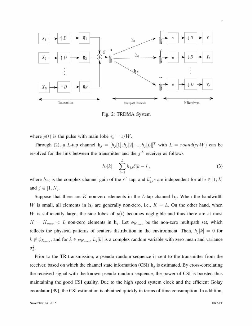
Fig. 2: TRDMA System
where p(t) is the pulse with main lobe τp = 1/W .
Through (2), a L-tap channel hj = [hj[1], hj[2], ..., hj[L]]T with L = round(τCW ) can be
resolved for the link between the transmitter and the jth receiver as follows
hj[k] =L∑i=1
hj,iδ[k − i], (3)
where hj,i is the complex channel gain of the ith tap, and h′j,is are independent for all i ∈ [1, L]
and j ∈ [1, N ].
Suppose that there are K non-zero elements in the L-tap channel hj . When the bandwidth
W is small, all elements in hj are generally non-zero, i.e., K = L. On the other hand, when
W is sufficiently large, the side lobes of p(t) becomes negligible and thus there are at most
K = Kmax < L non-zero elements in hj . Let ϕKmax be the non-zero multipath set, which
reflects the physical patterns of scatters distribution in the environment. Then, hj[k] = 0 for
k ∈ ϕKmax , and for k ∈ ϕKmax , hj[k] is a complex random variable with zero mean and variance
σ2k.
Prior to the TR-transmission, a pseudo random sequence is sent to the transmitter from the
receiver, based on which the channel state information (CSI) hj is estimated. By cross-correlating
the received signal with the known pseudo random sequence, the power of CSI is boosted thus
maintaining the good CSI quality. Due to the high speed system clock and the efficient Golay
coorelator [39], the CSI estimation is obtained quickly in terms of time consumption. In addition,
November 24, 2015 DRAFT
8
based on the real measurement in [40], the CSI is quite stationary given only slightly changing
of the environment, which indicates the channel need not to be re-probed very frequently and
the overhead price of channel probing is very small.
B. TRDMA downlink communication
In the TR system, the transmitter simultaneously communicates with multiple receivers.
Specifically, as shown in Fig. 2, the information to be transmitted to the jth receiver, denoted as
Xj , is first up-sampled by a backoff factor D to alleviate the interference, and then precoded by
a signature waveform gj . Actually, the symbol rate is lower down by D to limit the ISI. Note
that multiple designs of the signature waveform such as basic TR signature [25], zero-forcing
(ZF) signature [41] and minimal mean square error (MMSE) signature [30] can be utilized, and
the details will be discussed in the next section. After that, all signals to different receivers are
mixed together as follows
S[k] =N∑i=1
(X
[D]i ∗ gi
)[k]. (4)
where
X[D]i [k] =
Xi[k/D], if mod(k,D) = 0
0, otherwise(5)
The mixed signal is broadcast to all receivers through the rich-scatter environment. At the
receiver side, the jth receiver simply scales the received signal and down-samples it to obtain
the estimated signal Yj as follows
Yj[k] =(hj ∗ gj)[L]Xj[k −L
D]
+
2L−1D∑
l=1,l =L/D
(hj ∗ gj)[Dl]Xj[k − l]
+N∑
i=1,i=j
2L−1D∑l=1
(hj ∗ gi)[Dl]Xi[k − l]
+nj[k].
(6)
Without loss of generality, we design the signature waveform so that (hj ∗gj) has the resonating
effect at time index L. Then the first term in (6) is the desired signal, the second term is the
ISI, the third term is the IUI, and the last term is the noise.
November 24, 2015 DRAFT
9
The (6) can be re-written by replacing the convolution as inner product as follows
Yj[k] = H( LD)
j gjXj[k −L
D] +
(2L−1)/D∑l=1,l =L/D
H(l)j gjXj[k − l]
+
(2L−1)/D∑l=1
H(l)j
(N∑
i=1,i=j
giXi[k − l]
)+ nj[k],
(7)
where H(m)j is the mth row of the (2L − 1)/D × L matrix Hj decimated by rows of Toeplitz
matrix, which can be written as follows
Hj =
hj[D] hj[D − 1] · · · hj[1] 0 · · · · · · 0
hj[2D] hj[2D − 1] · · · · · · hj[1] 0 · · · 0...
... . . . . . . . . . . . . . . . ...
hj[L] hj[L− 1] · · · · · · · · · · · · · · · hj[1]...
... . . . . . . . . . . . . . . . ...
0 · · · 0 hj[L] · · · · · · hj[L−D + 1] hj[L− 2D]
0 · · · · · · 0 hj[L] · · · hj[L−D + 1] hj[L−D]
(8)
and thus H( LD)
j is the time-reversal channel
H( LD)
j = [hj(L)hj(L− 1) · · · hj(1)]. (9)
C. Expected Achievable Rate for Individual User
Let P and Pn be the average transmitting power and noise power, respectively, and (·)†
represent the conjugate transpose operator. According to (7) and the uplink-downlink duality
[42] [43] [44], the achievable rate of the jth receiver can be derived using its dual uplink format,
where the uniform power allocation is assumed. Then we take an expectation of the downlink
achievable rate as shown in (10). In the rest of the paper, we analyze the expected achievable
rate of the TR system.
Rj =W
DE
log21 +
PNg†jH
( LD)†
j H( LD)
j gj
PNg†j
(H†
jHj −H( LD)†
j H( LD)
j
)gj +
PN
∑Ni=1,i=j g
†jH
†iHigj + Pn
(10)
November 24, 2015 DRAFT
10
IV. TIME-REVERSAL MASSIVE MULTIPATH EFFECT
Similar to the quasi-orthogonal property in massive MIMO given an excessive amount of
antennas [4], the multipath profile of different users in the TR system will also be orthogonalized
given massive independent multipaths, which is called the TR Massive Multipath Effect
(TRMME).
Time-Reversal Massive Multipath Effect (TRMME): Under the asymptotic setting where
K = Kmax → ∞, QQ† converges to a diagonal matrix in distribution, and
[QQ†]lj ,lj∥hj∥2
d→ 1, (11)
where Q = [HT1 ,H
T2 , · · · ,HT
N ]T .
Proof: In order to reveal all the observable multipaths, e.g., K = Kmax, the bandwidth of the
system W should be large enough so that L/Kpmax → c where p > 2. Notice that every element
in QQ† is the sum of multiple independent variables, which converges to a Gaussian random
variable in distribution in the asymptotical scenario based on the central limit theorem. Since
Gaussian random variable is only determined by the first and second moment and obviously
each element in QQ† has zero mean, we only need to prove the largest variance of off-diagonal
element will converge to zero.
Based on the definition of Q, we have
QQ† =
H1H
†1 H1H
†2 · · · H1H
†N
H2H†1 H2H
†2 · · · H2H
†N
...... . . . · · ·
HNH†1 HNH
†2 · · · HNH
†N
. (12)
With (12), we can directly obtain
[QQ†]
lj ,lj= H
( LD)
j H( LD)†
j = ∥hj∥2. (13)
where [·]m,n represents the element in the mth row and the nth column of the matrix.
Then, we prove that QQ† is diagonal by examining the off-diagonal elements. Note that each
November 24, 2015 DRAFT
11
off-diagonal matrix (∀i = j) in (12), HiH†j , can be expanded as
HiH†j =
H
(1)i H
(1)†j H
(1)i H
(2)†j · · · H
(1)i H
( 2L−1D
)†j
H(2)i H
(1)†j H
(2)i H
(2)†j · · · H
(2)i H
( 2L−1D
)†j
...... . . . · · ·
H( 2L−1
D)
i H(1)†j H
( 2L−1D
)
i H(2)†j · · · H
( 2L−1D
)
i H( 2L−1
D)†
j
. (14)
From (14), we can see that each element of HiH†j ,[HiH
†j
]m,n
= H(m)i H
(n)†j , is the sum of
multiple independent random variables. Therefore, when Kmax is sufficiently large,[HiH
†j
]m,n
can be regarded as a Gaussian random variable, whose distribution is completely determined by
first and second moment.
Based on the independence between the channel taps and distinct receivers, it is obvious that
E[H
(m)i H
(n)†j
]= 0, (15)
while the second moment can be upper bounded as follows
E[|H(m)
i H(n)†j |2
](a)=
L∑l=1
E[|H(m)
i (l)|2|H(n)j (l)|2
],
(b)
≤L∑l=1
E[|H( L
D)
i (l)|2]E[|H( L
D)
j (l)|2],
(c)=
(∑Kmax
k=1 σ2k
)2L
,
(16)
where (a) is obtained directly from the independence, (b) is based on the matrix structure in
(8) and (c) comes from the fact that the Kmax multipaths are randomly distributed among the
L-tap channel and thus
E[|hj(m)|2
]= E
[|hj(n)|2
]=
∑Kmax
k=1 σ2k
L∀m,n. (17)
Note∑Kmax
k=1 σ2k < Kmax due to the pass loss attenuation. Therefore, (c) will converge to 0
given L/Kpmax → c where p > 2. From (15) and (16), we can conclude that
limKmax→∞
[HiH
†j
]m,n
= 0,∀m,n, and i = j. (18)
November 24, 2015 DRAFT
12
Next, let us examine the diagonal submatrix of QQ†, which can be expanded as
HjH†j =
H
(1)j H
(1)†j H
(1)j H
(2)†j · · · H
(1)j H
( 2L−1D
)†j
H(2)j H
(1)†j H
(2)j H
(2)†j · · · H
(2)j H
( 2L−1D
)†j
...... . . . · · ·
H( 2L−1
D)
j H(1)†j H
( 2L−1D
)
j H(2)†j · · · H
( 2L−1D
)
j H( 2L−1
D)†
j
. (19)
Similarly, each element[HjH
†j
]m,n
= H(m)j H
(n)†j can be regarded as Gaussian variable when
Kmax is sufficiently large. Since H(m)j and H
(n)j are independent when m = n, similar to (15)
and (16), we can derive E[H
(m)j H
(n)†j
]= 0 m = n,
E[|H(m)
j H(n)†j |2
]≤ (
∑Kmaxk=1 σ2
k)2
Lm = n,
(20)
and given L/Kpmax → c where p > 2, we have derived that
limKmax→∞
[HjH
†j
]m,n
= 0,∀j, and m = n. (21)
Therefore, we can conclude that QQ† is diagonal. This completes the proof.
The assumption that Kmax → ∞ is just for analyzing the asymptotical achievable rate of the
TR system as the assumption Mt → ∞ in early massive MIMO works. In practice, we only
need that Kmax is large enough to achieve massive multipath effect. Based on the real indoor
measurement in Sec. VI.B, we have demonstrated that the number of the resolved multipaths
in a typical indoor environment is large enough given a sufficiently large bandwidth. Even
though Kmax is a fixed value given the power and environment, there still exists other method
to realize massive multipaths. Since the TR and MIMO technology are not mutually exclusive,
the independent multipaths can be easily scaled up by adding a few antennas. How to realize
massive multipaths is discussed with real indoor measurement later in Section VI.
V. EXPECTED ACHIEVABLE RATE UNDER DIFFERENT SIGNATURE WAVEFORMS
In this section, we analyze the expected achievable rate under three different designs of
signature waveform: basic TR signature [25], ZF signature [41] and MMSE signature [30].
With utilization of TRMME in Section IV, the asymptotical achievable rate with three signature
waveforms is further derived.
November 24, 2015 DRAFT
13
A. Expected Achievable Rate
The three signature waveforms are shown in the following,
gj =
H
(L/D)†j /∥H(L/D)
j ∥, Basic TR
cZFQ†(QQ†)
−1elj , ZF
cMMSE(Q†Q+ 1
puI)
−1Q†elj , MMSE
(22)
where cZF and cMMSE are normalization constants, Q = [HT1 ,H
T2 , · · · ,HT
N ]T , elj is an
elementary vector with lj = (j − 1)(2L − 1)/D + L/D, I is the identity matrix, and pu is
the transmitting signal-to-noise ratio (SNR) of each user defined as
pu =P
NPn
. (23)
With the definition of Q and elj above, we have
Q†elj = H(L/D)†j . (24)
Note that under the multipath-rich scenario, ZF signature can completely cancel out the
interference given large amount of independent multipaths. In addition, MMSE signature has
a simpler closed form solution with the fixed dual uplink power allocation [30].
Theorem 1 (Expected Achievable Rate): The expected achievable rate of the TR system
with basic TR signature, ZF signature, and MMSE signature can be written as follows
RBasicj =
W
DE[log2
(1 +
pu∥hj∥4
pu([QQ†QQ†]lj ,lj − ∥hj∥4) + ∥hj∥2
)],
RZFj =
W
DE
[log2
(1 +
pu
[(QQ†)−1]lj ,lj
)],
RMMSEj =
W
DE
log2 1[
(I+ puQQ†)−1]lj ,lj
.
(25)
The proof for Theorem 1 is listed in the appendix. Even though (25) seems similar to those for
MIMO MRC/ZF/MMSE receivers, the matrix Q is different from the channel profile matrix in
MIMO system, which results in significantly different derivation of the asymptotical performance
in the TR system. More specifically, due to the large channel delay spread in the TR system, there
exists ISI. Therefore, backoff factor D is adopted in our paper and the channel profile Hi becomes
the decimated Toeplitz matrix, which is much more complicated than that in MIMO system.
November 24, 2015 DRAFT
14
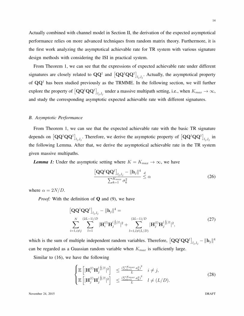
Actually combined with channel model in Section II, the derivation of the expected asymptotical
performance relies on more advanced techniques from random matrix theory. Furthermore, it is
the first work analyzing the asymptotical achievable rate for TR system with various signature
design methods with considering the ISI in practical system.
From Theorem 1, we can see that the expressions of expected achievable rate under different
signatures are closely related to QQ† and[QQ†QQ†]
lj ,lj. Actually, the asymptotical property
of QQ† has been studied previously as the TRMME. In the following section, we will further
explore the property of[QQ†QQ†]
lj ,ljunder a massive multipath setting, i.e., when Kmax → ∞,
and study the corresponding asymptotic expected achievable rate with different signatures.
B. Asymptotic Performance
From Theorem 1, we can see that the expected achievable rate with the basic TR signature
depends on[QQ†QQ†]
lj ,lj. Therefore, we derive the asymptotic property of
[QQ†QQ†]
lj ,ljin
the following Lemma. After that, we derive the asymptotical achievable rate in the TR system
given massive multipaths.
Lemma 1: Under the asymptotic setting where K = Kmax → ∞, we have[QQ†QQ†]
lj ,lj− ∥hj∥4∑Kmax
k=1 σ2k
d
≤ α (26)
where α = 2N/D.
Proof: With the definition of Q and (9), we have[QQ†QQ†]
lj ,lj− ∥hj∥4 =
N∑i=1,i=j
(2L−1)/D∑l=1
|H(l)i H
( LD)†
j |2 +(2L−1)/D∑
l=1,l =(L/D)
|H(l)j H
( LD)†
j |2,(27)
which is the sum of multiple independent random variables. Therefore,[QQ†QQ†]
lj ,lj−∥hj∥4
can be regarded as a Guassian random variable when Kmax is sufficiently large.
Similar to (16), we have the followingE[|H(l)
i H( LD)†
j |2]
≤ (∑Kmax
k=1 σ2k)
2
Li = j,
E[|H(l)
j H( LD)†
j |2]
≤ (∑Kmax
k=1 σ2k)
2
Ll = (L/D).
(28)
November 24, 2015 DRAFT
15
Therefore, with Kmax → ∞, the expectation of[QQ†QQ†]
lj ,lj− ∥hj∥4 can be bounded by
E[[QQ†QQ†]
lj ,lj− ∥hj∥4
]≤ N(2L− 1)
D
(∑Kmax
k=1 σ2k)
2
L,
≤ α
(Kmax∑k=1
σ2k
)2
,
(29)
with α = 2N/D.
Similar to the argument in the derivation of (17), the fourth moment of hj(m) can be given
as
E[|hj(m)|4
]= E
[|hj(n)|4
]= 2
(∑Kmax
k=1 σ2k
L
)2
∀m,n. (30)
Then, we have, E[|H(l)
i H( LD)†
j |4]
≤ 4(∑Kmax
k=1 σ2k)
4
L3 i = j
E[|H(l)
j H( LD)†
j |4]
≤ 4(∑Kmax
k=1 σ2k)
4
L3 l = (L/D)(31)
As Kmax → ∞, L/Kpmax → c where p > 2 holds in the multipath-rich scenario. Therefore,
the variance of[QQ†QQ†]
lj ,lj−∥hj∥4 goes to zero as Kmax → ∞. Combining the first moment
in (29), we can derive the result in Lemma 1. This completes the proof.
Remark: In a massive MIMO system, when the number of antennas grows large, the random
channel vectors between the users and the base station become pairwisely orthogonal [45].
Similarly, in a TR system, when the number of multipaths grows large, a pairwisely orthogonal
property among the random channel vectors between the receivers and the transmitter exists, as
shown in the TRMME. On the other hand, while, in a massive MIMO system, simple matched
filter processing can completely remove the uncorrelated noise and interference with an infinite
number of antennas [4], due to the existence of ISI in a TR system, the basic TR signature
cannot completely remove the interference in general. Therefore, Lemma 1 is needed for the
derivation of the asymptotic expected achievable rate for the TR system with basic TR signature.
Based on the TRMME and Lemma 1, we can analyze the asymptotic expected achievable rate
under different signatures, and the results are summarized in the following Theorem.
November 24, 2015 DRAFT
16
Theorem 2: When Kmax → ∞, the asymptotic expected achievable rate with the ZF signature
and MMSE signature satisfy thatRZF
j
W/D=
RMMSEj
W/D= E
[log2
(1 + pu∥hj∥2
)], (32)
while the asymptotic expected achievable rate with the basic TR signature satisfies the following
inequality,
RBasicj
W/D≥ E
log21 +
pu∥hj∥2
puα(∑Kmax
k=1 σ2k)
2
∥hj∥2 + 1
. (33)
Proof: According to the TRMME, we have
limKmax→∞
[(QQ†)−1
]lj ,lj
∥hj∥2= 1. (34)
Then, according to (50), the asymptotic expected achievable rate under ZF signature isRZF
j
W/D→ E
[log2
(1 + pu∥hj∥2
)]. (35)
Similarly, with the TRMME, we can also have[(I+ puQQ†)−1
]lj ,lj
→[(I+ puλ)
−1]lj ,lj
=1
1 + pu∥hj∥2(36)
By substituting (36) into (56), the asymptotic expected achievable rate under MMSE signature
isRMMSE
j
W/D→ E
[log2
(1 + pu∥hj∥2
)]. (37)
Finally, by substituting (26) of Lemma 1 into (46), the asymptotic expected achievable rate
under basic TR signature can be lower bounded as
RBasicj
W/D≥ E
log21 +
pu∥hj∥2
puα(∑Kmax
k=1 σ2k)
2
∥hj∥2 + 1
. (38)
This completes the proof.
From Theorem 2, we can see that the ZF and MMSE signatures generally outperform the
basic TR signature in terms of expected achievable rate. However, when D is sufficiently large
so thatα(
∑Kmaxk=1 σ2
k)2
∥hj∥2 goes to zero, this is the case when the ISI and IUI are eliminated, then
the basic TR signature can achieve the same asymptotic expected achievable rate with ZF and
MMSE signatures.
November 24, 2015 DRAFT
17
50 100 150 200 250 300 350
1.5
2
2.5
3
3.5
4
4.5
5
5.5
6
6.5
Kmax
DR
j/W
(bits/s/Hz)
D = Kmax pu=5dB N = 6
Asymptotical Results of ZF/MMSEZFMMSElower bound of Basic TRBasic TR
(a) N = 6
50 100 150 200 250 300 350 400
1.5
2
2.5
3
3.5
4
4.5
5
5.5
6
6.5
Kmax
DR
j/W
(bits/s/Hz)
D = Kmax pu=5dB N = 20
Asymptotical Results of ZF/MMSEZFMMSElower bound of Basic TRBasic TR
(b) N = 20
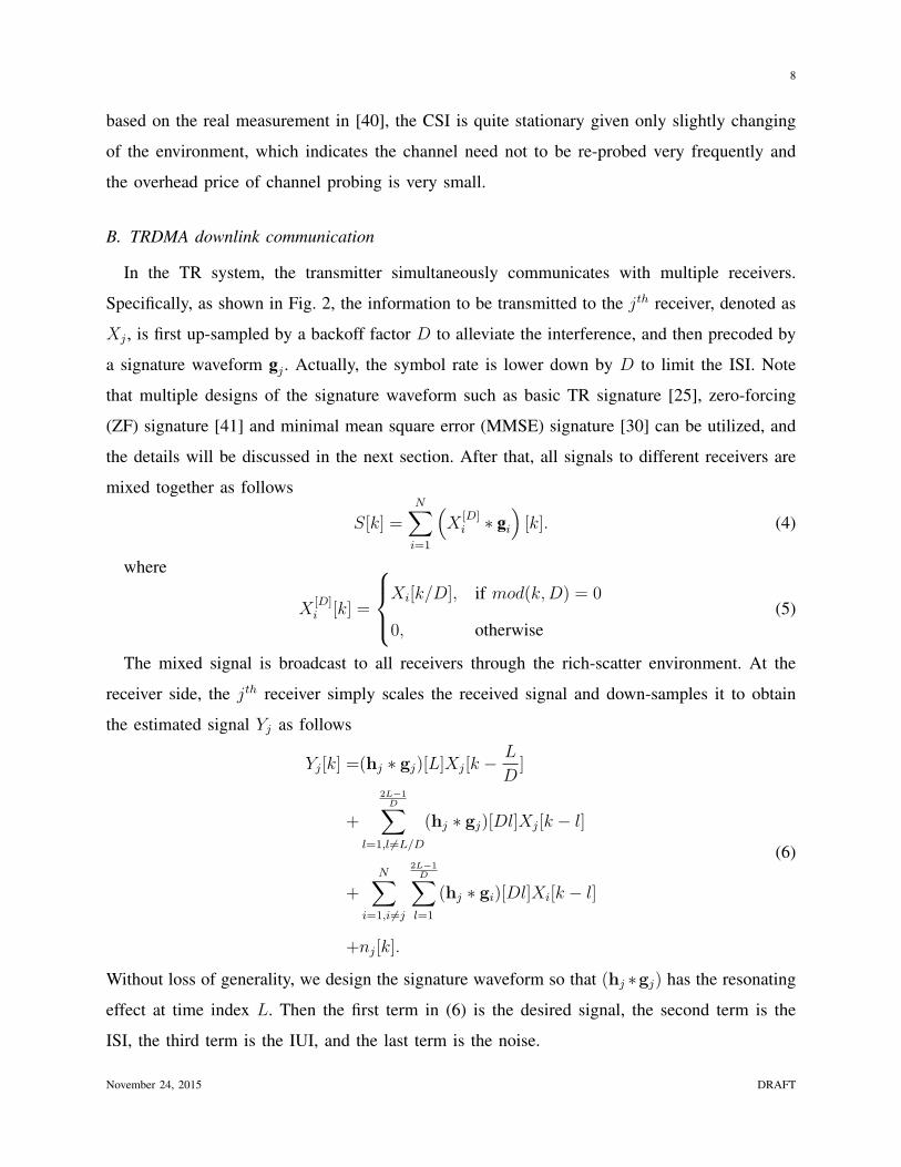
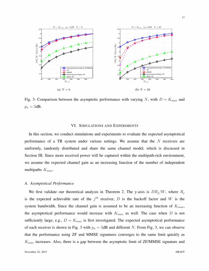
Fig. 3: Comparison between the asymptotic performance with varying N , with D = Kmax and
pu = 5dB.
VI. SIMULATIONS AND EXPERIMENTS
In this section, we conduct simulations and experiments to evaluate the expected asymptotical
performance of a TR system under various settings. We assume that the N receivers are
uniformly, randomly distributed and share the same channel model, which is discussed in
Section III. Since more received power will be captured within the multipath-rich environment,
we assume the expected channel gain as an increasing function of the number of independent
multipaths Kmax.
A. Asymptotical Performance
We first validate our theoretical analysis in Theorem 2. The y-axis is DRj/W , where Rj
is the expected achievable rate of the jth receiver, D is the backoff factor and W is the
system bandwidth. Since the channel gain is assumed to be an increasing function of Kmax,
the asymptotical performance would increase with Kmax as well. The case when D is not
sufficiently large, e.g., D = Kmax is first investigated. The expected asymptotical performance
of each receiver is shown in Fig. 3 with pu = 5dB and different N . From Fig. 3, we can observe
that the performance using ZF and MMSE signatures converges to the same limit quickly as
Kmax increases. Also, there is a gap between the asymptotic limit of ZF/MMSE signature and
November 24, 2015 DRAFT

18
50 100 150 200 250 300 350
1.5
2
2.5
3
3.5
4
4.5
5
5.5
6
6.5
Kmax
DR
j/W
(bits/s/Hz)
D = Kmax pu=5dB N = 6
Asymptotical Results of ZF/MMSEZFMMSElower bound of Basic TRBasic TR
(a) D = Kmax
50 100 150 200 250 300 350 400
1.5
2
2.5
3
3.5
4
4.5
5
5.5
6
6.5
Kmax
DR
j/W
(bits/s/Hz)
D = K1.5max pu = 5dB N = 6
Asymptotical Results of ZF/MMSEZFMMSELower Bound of Basic TRBasic TR
(b) D = K1.5max
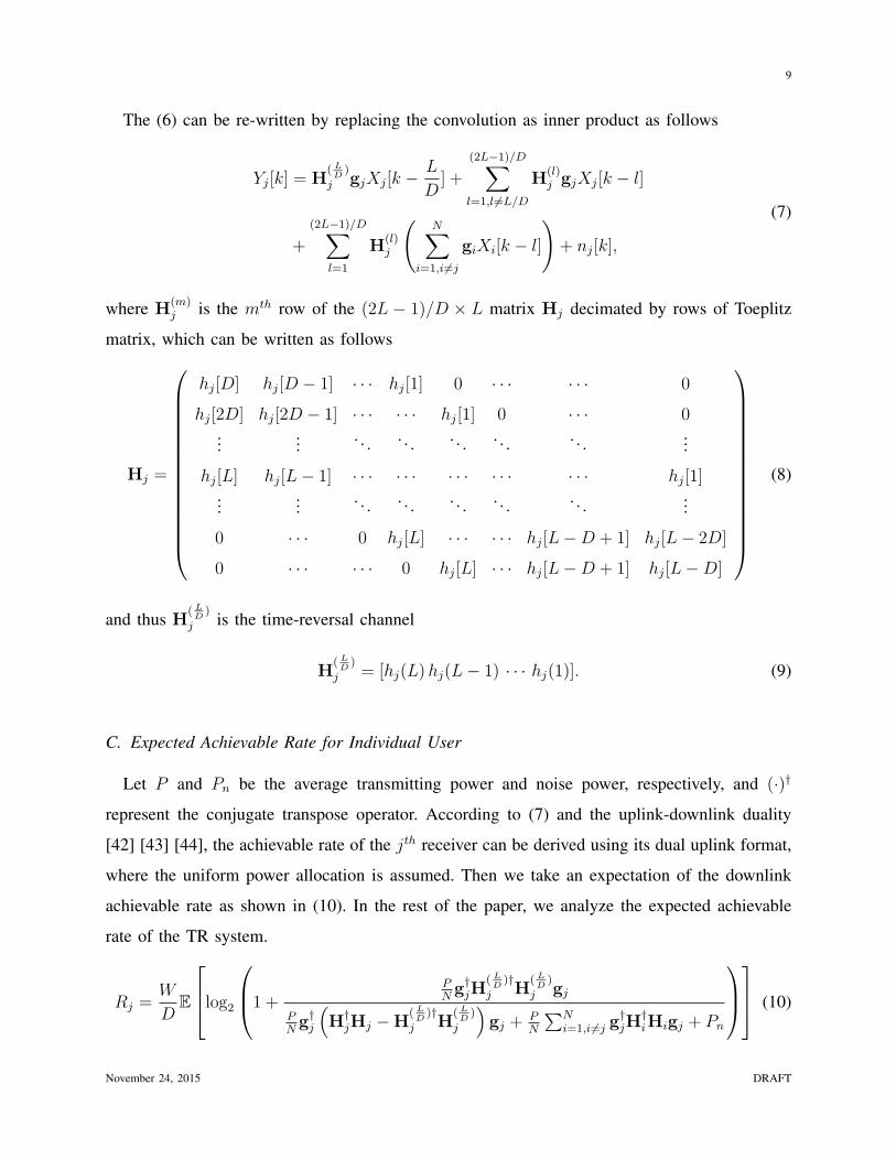
Fig. 4: Comparison between the asymptotic performance with varying D, with N = 6 and
pu = 5dB.
the lower bound of the basic TR signature. This is mainly because when the basic TR signature
is used and the D is not large enough, there exists residual ISI and IUI andα(
∑Kmaxk=1 σ2
k)2
∥hj∥2 cannot
be negligible. By comparing the results with N = 6 and N = 20, we notice that the gap becomes
even larger when N increases, which is due to the increase of α = 2N/D.
We also compare the asymptotical performance of basic TR, ZF and MMSE signatures by
varying D. It can be seen in Fig. 4 that the gap between the asymptotic performance of ZF/MMSE
signature and that of the basic TR signature becomes much smaller when D and Kmax are both
sufficiently larger. Such a phenomenon is mainly due to less severe ISI and IUI and a much
smallerα(
∑Kmaxk=1 σ2
k)2
∥hj∥2 . Therefore, the basic TR signature can achieve the same optimal asymptotic
expected achievable rate with ZF and MMSE signatures with sufficiently large D.
B. The Number of Observable Independent Multipaths K in a Typical Indoor Environment
To achieve the asymptotic performance in Theorem 2 requires the TR system to operate in
a multipath-rich environment. In this subsection, we investigate the property of K in a typical
indoor environment using real-world measurements. First, we demonstrate that, in a typical
office, the number of resolvable multipaths is large with a sufficiently large bandwidth. Then,
November 24, 2015 DRAFT
19
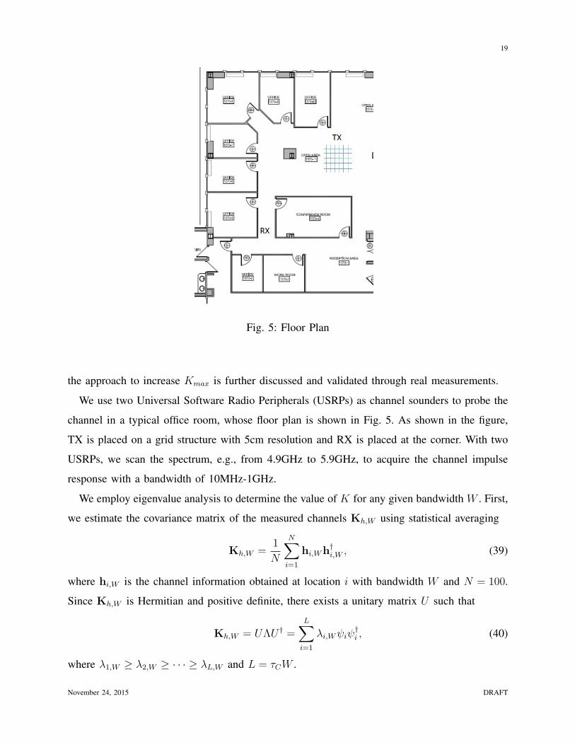
Fig. 5: Floor Plan
the approach to increase Kmax is further discussed and validated through real measurements.
We use two Universal Software Radio Peripherals (USRPs) as channel sounders to probe the
channel in a typical office room, whose floor plan is shown in Fig. 5. As shown in the figure,
TX is placed on a grid structure with 5cm resolution and RX is placed at the corner. With two
USRPs, we scan the spectrum, e.g., from 4.9GHz to 5.9GHz, to acquire the channel impulse
response with a bandwidth of 10MHz-1GHz.
We employ eigenvalue analysis to determine the value of K for any given bandwidth W . First,
we estimate the covariance matrix of the measured channels Kh,W using statistical averaging
Kh,W =1
N
N∑i=1
hi,Wh†i,W , (39)
where hi,W is the channel information obtained at location i with bandwidth W and N = 100.
Since Kh,W is Hermitian and positive definite, there exists a unitary matrix U such that
Kh,W = UΛU † =L∑i=1
λi,Wψiψ†i , (40)
where λ1,W ≥ λ2,W ≥ · · · ≥ λL,W and L = τCW .
November 24, 2015 DRAFT
20
20 40 60 80 100 1200
0.1
0.2
0.3
0.4
0.5
0.6
0.7
0.8
0.9
1
number of significant eigenvalues
\% o
f cap
ture
d en
ergy
10MHz100MHz400MHz800MHz
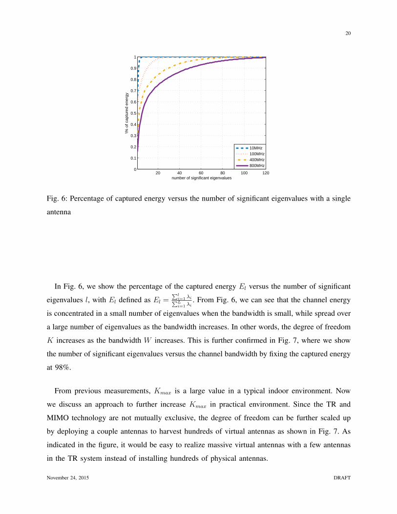
Fig. 6: Percentage of captured energy versus the number of significant eigenvalues with a single
antenna
In Fig. 6, we show the percentage of the captured energy El versus the number of significant
eigenvalues l, with El defined as El =∑l
i=1 λi∑Li=1 λi
. From Fig. 6, we can see that the channel energy
is concentrated in a small number of eigenvalues when the bandwidth is small, while spread over
a large number of eigenvalues as the bandwidth increases. In other words, the degree of freedom
K increases as the bandwidth W increases. This is further confirmed in Fig. 7, where we show
the number of significant eigenvalues versus the channel bandwidth by fixing the captured energy
at 98%.
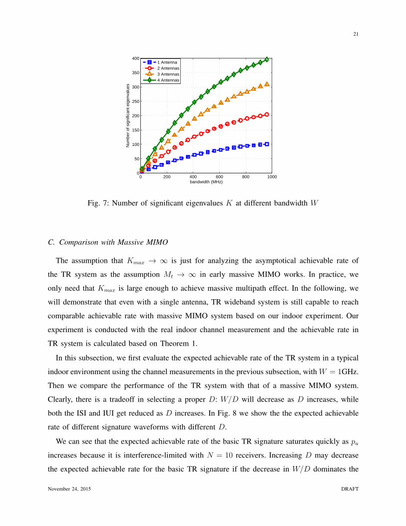
From previous measurements, Kmax is a large value in a typical indoor environment. Now
we discuss an approach to further increase Kmax in practical environment. Since the TR and
MIMO technology are not mutually exclusive, the degree of freedom can be further scaled up
by deploying a couple antennas to harvest hundreds of virtual antennas as shown in Fig. 7. As
indicated in the figure, it would be easy to realize massive virtual antennas with a few antennas
in the TR system instead of installing hundreds of physical antennas.
November 24, 2015 DRAFT
21
0 200 400 600 800 10000
50
100
150
200
250
300
350
400
bandwidth (MHz)
Num
ber
of s
igni
fican
t eig
enva
lues
1 Antenna2 Antennas3 Antennas4 Antennas
Fig. 7: Number of significant eigenvalues K at different bandwidth W
C. Comparison with Massive MIMO
The assumption that Kmax → ∞ is just for analyzing the asymptotical achievable rate of
the TR system as the assumption Mt → ∞ in early massive MIMO works. In practice, we
only need that Kmax is large enough to achieve massive multipath effect. In the following, we
will demonstrate that even with a single antenna, TR wideband system is still capable to reach
comparable achievable rate with massive MIMO system based on our indoor experiment. Our
experiment is conducted with the real indoor channel measurement and the achievable rate in
TR system is calculated based on Theorem 1.
In this subsection, we first evaluate the expected achievable rate of the TR system in a typical
indoor environment using the channel measurements in the previous subsection, with W = 1GHz.
Then we compare the performance of the TR system with that of a massive MIMO system.
Clearly, there is a tradeoff in selecting a proper D: W/D will decrease as D increases, while
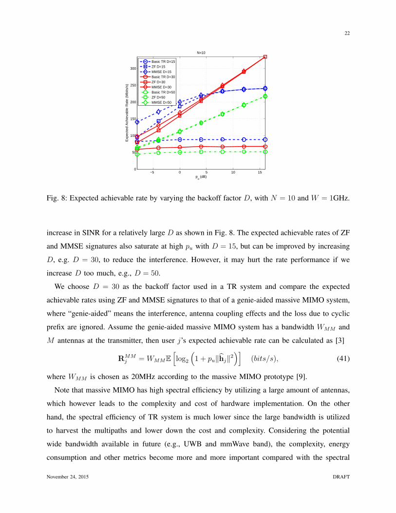
both the ISI and IUI get reduced as D increases. In Fig. 8 we show the the expected achievable
rate of different signature waveforms with different D.
We can see that the expected achievable rate of the basic TR signature saturates quickly as pu
increases because it is interference-limited with N = 10 receivers. Increasing D may decrease
the expected achievable rate for the basic TR signature if the decrease in W/D dominates the
November 24, 2015 DRAFT
22
−5 0 5 10 150
50
100
150
200
250
300
pu (dB)
Exp
ect
ed
Ach
ieva
ble
Ra
te (
Mb
its/s
)
N=10
Basic TR D=15ZF D=15MMSE D=15Basic TR D=30ZF D=30MMSE D=30Basic TR D=50ZF D=50MMSE D=50
Fig. 8: Expected achievable rate by varying the backoff factor D, with N = 10 and W = 1GHz.
increase in SINR for a relatively large D as shown in Fig. 8. The expected achievable rates of ZF
and MMSE signatures also saturate at high pu with D = 15, but can be improved by increasing
D, e.g. D = 30, to reduce the interference. However, it may hurt the rate performance if we
increase D too much, e.g., D = 50.
We choose D = 30 as the backoff factor used in a TR system and compare the expected
achievable rates using ZF and MMSE signatures to that of a genie-aided massive MIMO system,
where “genie-aided” means the interference, antenna coupling effects and the loss due to cyclic
prefix are ignored. Assume the genie-aided massive MIMO system has a bandwidth WMM and
M antennas at the transmitter, then user j’s expected achievable rate can be calculated as [3]
RMMj = WMME
[log2
(1 + pu∥hj∥2
)](bits/s), (41)
where WMM is chosen as 20MHz according to the massive MIMO prototype [9].
Note that massive MIMO has high spectral efficiency by utilizing a large amount of antennas,
which however leads to the complexity and cost of hardware implementation. On the other
hand, the spectral efficiency of TR system is much lower since the large bandwidth is utilized
to harvest the multipaths and lower down the cost and complexity. Considering the potential
wide bandwidth available in future (e.g., UWB and mmWave band), the complexity, energy
consumption and other metrics become more and more important compared with the spectral
November 24, 2015 DRAFT

23
−5 0 5 10 150
50
100
150
200
250
300
350
400
pu (dB)
Expecte
d A
chie
vable
Rate
(M
bits/s
)
genie−aided MIMO M=200
genie−aided MIMO M=400
genie−aided MIMO M=800
ZF N=10 D=30
MMSE N=10 D=30
(a) Expected achievable rate comparison between TR and
massive MIMO systems, with W = 1GHz, N = 10 and
D = 30 for the TR system, and WMM = 20MHz.
−5 0 5 10 15750
800
850
900
950
1000
pu (dB)
Ba
nd
wid
th o
f T
R S
yste
m (
MH
z)
M = 200M = 400M = 800
(b) Bandwidth requirement of TR system with MMSE signa-
ture to achieve the same achievable rate of a massive MIMO
system with WMM = 20MHz.
Fig. 9: Comparison of the achievable rate in TR and massive MIMO system
efficiency given the comparable achievable can be achieved as shown in Fig. 9a. Moreover, the
bandwidth requirement for TR system to achieve the same achievable rate with a massive MIMO
system (with hundreds of antennas and 20MHz bandwidth) is shown in Fig. 9b. As shown in
Fig. 9b, to achieve the same achievable rate as a massive MIMO system with a larger number
of antennas, a larger bandwidth is required by the TR system. Note that the performance of TR
is obtained from real data, while that of massive MIMO is the best case scenario. Another note
is the one requires a large number of antennas, while the other larger bandwidth.
VII. CONCLUSION
In this paper, we demonstrate that the TR technology, through harvesting the naturally existing
virtual antennas, can offer a cost effective solution to achieve the desired massive MIMO
performance demanded in the possible future 5G systems. We derive the achievable rate of the TR
system with basic TR, ZF, and MMSE signatures under the asymptotic limiting settings. We prove
theoretically and validate with simulations that the TR system with ZF and MMSE signatures
can asymptotically achieve the limiting achievable rate, where the interference is completely
November 24, 2015 DRAFT

24
eliminated. When the backoff factor is sufficiently large, the basic TR signature can also achieve
the same asymptotic achievable rate. Finally, based on the real channel measurements, experiment
is conducted to show that the single-antenna TR wideband system can achieve comparable rates
as that of the massive MIMO system. Note that by utilizing the environment as virtual antenna
array and computing resource, the implementation complexity of the TR system is much lower.
What a TR system needs is large enough bandwidth to harvest multipaths in the environment.
With highspeed ADC becoming more affordable, wider bandwidth is readily available. On the
contrary, the huge number of antennas demanded by a massive MIMO system may continue to
face the challenge of unavoidable coupling effects.
APPENDIX
A. Expected Achievable Rate under Basic TR Signature
From (22), the basic TR signature is gj = H(L/D)†j /∥H(L/D)
j ∥. Therefore, we have
g†jH
( LD)†
j H( LD)
j gj = ∥H( LD)
j ∥2, (42)
and
g†j
(N∑i=1
H†iHi
)gj =
H( LD)
j Q†QH( LD)†
j
∥H( LD)
j ∥2. (43)
According to the definition of H(L/D)j , we have ∥H( L
D)
j ∥2 = ∥hj∥2, and H(L/D)j is the (L/D)th
row of Hj and thus lthj row of Q. Therefore, (42) and (43) can be re-written as
g†jH
( LD)†
j H( LD)
j gj = ∥hj∥2, (44)
and
g†j
(N∑i=1
H†iHi
)gj =
[QQ†QQ†]
lj ,lj
∥hj∥2, (45)
where [ · ]lj ,lj is the (lj, lj) element of the matrix.
Substituting (44) and (45) into (10), the expected achievable rate of jth receiver with the basic
TR signature can be written as
RBasicj =
W
DE[log2
(1 +
pu∥hj∥4
pu([QQ†QQ†]lj ,lj − ∥hj∥4) + ∥hj∥2
)]. (46)
November 24, 2015 DRAFT
25
B. Expected Achievable Rate under ZF Signature
With the ZF signature gj = cZFQ†(QQ†)
−1elj , we have
H1gj
...
HNgj
= Qgj = cZFQQ†(QQ†)−1elj = cZFelj . (47)
According to (47), we can derive the following
g†jH
†iHigj =
0, ∀i = j;
g†jH
( LD)†
j H( LD)
j gj = c2ZF , i = j.(48)
Substituting (48) into (10), we can see that both the ISI and IUI are eliminated, and thus the
expected achievable rate with ZF signature can be written as
RZFj =
W
DE[log2
(1 + puc
2ZF
)]. (49)
Since g†jgj = c2ZF [(QQ†)
−1]lj ,lj = 1, the expected achievable rate with ZF signature in (49)
can be re-written as
RZFj =
W
DE
[log2
(1 +
pu
[(QQ†)−1]lj ,lj
)]. (50)
C. Expected Achievable Rate under MMSE Signature
According to (22) and the Woodbury matrix identity [46], the MMSE signature can be written
as
gj = cMMSE
(Q†Q+
1
puI
)−1
H( LD)†
j ,
=cMMSEΛ
−1j H
( LD)†
j
H( LD)
j Λ−1j H
( LD)†
j + 1, (51)
where Λj , Q†Q−H( LD)†
j H( LD)
j + (1/pu)I.
By multiplying both sides in (51) with H( LD)
j , we can derive the following
H( LD)
j Λ−1j H
( LD)†
j =1
1−H( LD)
j
(Q†Q+ 1
puI)−1
H( LD)†
j
− 1. (52)
November 24, 2015 DRAFT

26
Moreover, according to (51), we have
g†jH
( LD)†
j H( LD)
j gj =c2MMSE
(H
( LD)
j Λ−1j H
( LD)†
j
)2(H
( LD)
j Λ−1j H
( LD)†
j + 1)2 , (53)
and
g†jΛjgj =
c2MMSEH( LD)
j Λ−1j H
( LD)†
j(H
( LD)
j Λ−1j H
( LD)†
j + 1)2 . (54)
Then, the expected achievable rate in (10) can be re-rewritten as
RMMSEj
(a)=W
DE
log21 +
g†jH
( LD)†
j H( LD)
j gj
g†j
(H†
jHj −H( LD)†
j H( LD)
j +∑
i =j H†iHi +
1puI)gj
,
(b)=W
DE
log21 +
g†jH
( LD)†
j H( LD)
j gj
g†jΛjgj
,(c)=W
DE[log2
(1 +H
( LD)
j Λ−1j H
( LD)†
j
)],
(55)
where (a) is the direct result from g†jgj = 1, (b) comes from the definition of Λj , and (c) are
based on (53) and (54).
By substituting (52) into (55), the expected achievable rate with MMSE signature can be
further simplified as
RMMSEj =
W
DE
log2 1
1−H( LD)
j
(Q†Q+ 1
puI)−1
H( LD)†
j
,
=W
DE
log2 1
1−[Q(Q†Q+ 1
puI)−1
Q†]lj ,lj
,
=W
DE
log2 1[
(I+ puQQ†)−1]lj ,lj
,
(56)
where the second equality comes from the definition of H( LD)
j and the last equality comes from
the following derivation by utilizing the Woodbury matrix identity [46],(I+ puQQ†)−1
= I−Q
(1
puI+Q†Q
)−1
Q†. (57)
November 24, 2015 DRAFT
27
Up to now, we have derived the expected achievable rate under different designs of signature
waveform, and the results are summarized in Theorem 1.
REFERENCES
[1] Cisco, “Visual networking index,” Cisco white paper, 2015.
[2] J. Andrews, S. Buzzi, C. Wan, S. Hanly, A. Lozano, A. Soong, and J. Zhang, “What will 5g be?” IEEE J. Sel. Areas
Commun., vol. 32, no. 6, pp. 1065–1082, 2014.
[3] H. Ngo, E. Larsson, and T. Marzetta, “Energy and spectral efficiency of very large multiuser mimo systems,” IEEE Trans.
Commun., vol. 61, no. 4, pp. 1436–1449, 2013.
[4] T. Marzetta, “Noncooperative cellular wireless with unlimited numbers of base station antennas,” IEEE Trans. Wireless
Commun., vol. 9, no. 11, pp. 3590–3600, 2010.
[5] F. Boccardi, R. Heath, A. Lozano, T. Marzetta, and P. Popovski, “Five disruptive technology directions for 5g,” IEEE
Commun. Mag., vol. 52, no. 2, pp. 74–80, 2014.
[6] J. Liu, H. Minn, and A. Gatherer, “The death of 5g part 2: Will analog be the death of massive mimo?”
http://http://www.comsoc.org/ctn/death-5g-part-2-will-analog-be-death-massive-mimo, June 2015.
[7] X. Artiga, B. Devillers, and J. Perruisseau-Carrier, “Mutual coupling effects in multi-user massive mimo base stations,” in
Proc. IEEE APSURSI, pp. 1–2, 2012.
[8] C. Masouros, M. Sellathurai, and T. Ratnarajah, “Large-scale mimo transmitters in fixed physical spaces: the effect of
transmit correlation and mutual coupling,” IEEE Trans. Commun., vol. 61, no. 7, pp. 2794–2804, 2013.
[9] J. Vieira, S. Malkowsky, K. Nieman, Z. Miers, N. Kundargi, L. Liu, I. Wong, V. Owall, O. Edfors, and F. Tufvesson, “A
flexible 100-antenna testbed for massive mimo,” in Proc. IEEE GC Wkshps, pp. 287–293, 2014.
[10] R. Saadane, A. Menouni, R. Knopp, and D. Aboutajdine, “Empirical eigenanalysis of indoor uwb propagation channels,”
in Proc. IEEE GLOBECOM, vol. 5, pp. 3215–3219, 2004.
[11] A. M. Hayar, R. Knopp, and R. Saadane, “Subspace analysis of indoor uwb channels,” EURASIP J. Appl. Signal Process.,
vol. 2005, pp. 287–295, 2005.
[12] Y. Chen, F. Han, Y. Yang, H. Ma, Y. Han, C. Jiang, H. Lai, D. Claffey, Z. Safar, and K. J. R. Liu, “Time-reversal wireless
paradigm for green internet of things: an overview,” IEEE Internet Things J., vol. 1, no. 1, pp. 81–98, 2014.
[13] A. Inamdar, S. Rylov, A. Talalaevskii, A. Sahu, S. Sarwana, D. Kirichenko, I. Vernik, T. Filippov, and D. Gupta, “Progress
in design of improved high dynamic range analog-to-digital converters,” IEEE Trans. Appl. Supercond., vol. 19, no. 3, pp.
670–675, 2009.
[14] T. Rappaport, S. Sun, R. Mayzus, H. Zhao, Y. Azar, K. Wang, G. Wong, J. Schulz, M. Samimi, and F. Gutierrez, “Millimeter
wave mobile communications for 5g cellular: It will work!” IEEE Access, vol. 1, pp. 335–349, 2013.
[15] P. Smulders and L. Correia, “Characterisation of propagation in 60 ghz radio channels,” Electron. Commun. Eng. J., vol. 9,
no. 2, pp. 73–80, Apr 1997.
[16] F. Han, Y. Yang, B. Wang, Y. Wu, and K. J. R. Liu, “Time-reversal division multiple access over multi-path channels,”
IEEE Trans. Commun., vol. 60, no. 7, pp. 1953–1965, 2012.
[17] B. P. Bogert, “Demonstration of delay distortion correction by time-reversal techniques,” IRE Trans. Commun. Syst., vol. 5,
no. 3, pp. 2–7, 1957.
[18] M. Fink and C. Prada, “Acoustic time-reversal mirrors,” Inverse problems, vol. 17, no. 1, p. R1, 2001.
November 24, 2015 DRAFT
28
[19] S. Lehman and A. Devaney, “Transmission mode time-reversal super-resolution imaging,” J. Acoust. Soc. Amer., vol. 113,
no. 5, pp. 2742–2753, 2003.
[20] D. Liu, G. Kang, L. Li, Y. Chen, S. Vasudevan, W. Joines, Q. Liu, J. Krolik, and L. Carin, “Electromagnetic time-reversal
imaging of a target in a cluttered environment,” IEEE Trans. Antennas Propag., vol. 53, no. 9, pp. 3508–3066, 2005.
[21] G. Edelmann, T. Akal, W. Hodgkiss, S. Kim, W. Kuperman, and H. Song, “An initial demonstration of underwater acoustic
communication using time reversal,” IEEE J. Ocean. Eng., vol. 27, no. 3, pp. 602–609, 2002.
[22] A. Derode, P. Roux, and M. Fink, “Robost acoustic time reversal with high order multiple scattering,” Phys. Rev. Lett.,
vol. 75, pp. 4206–4209, 1995.
[23] H. Nguyen, J. Anderson, and G. Pedersen, “The potential of time reversal techniques in multiple element antenna systems,”
IEEE Commun. Lett., vol. 9, no. 1, pp. 40–42, 2005.
[24] R. de Lacerda Neto, A. Hayar, and M. Debbah, “Channel division multiple access based on high uwb channel temporal
resolution,” in Proc. IEEE VTC, pp. 1–5, 2006.
[25] B. Wang, Y. Wu, F. Han, Y. Yang, and K. J. R. Liu, “Green wireless communications: a time-reversal paradigm,” IEEE J.
Select. Areas Commun., vol. 29, no. 8, pp. 1698–1710, 2011.
[26] M.-A. Bouzigues, I. Siaud, M. Helard, and A.-M. Ulmer-Moll, “Turn back the clock: time reversal for green radio
communications,” IEEE Veh. Technol. Magazine, vol. 8, no. 1, pp. 49–56, 2013.
[27] R. de Lacerda, L. Cottatellucci, A. Hayar, and M. Debbah, “Asymptotic analysis of channel division multiple access
schemes for ultra-wideband systems,” in Proc. IEEE SPAWC, pp. 186–190, 2008.
[28] R. de Lacerda, A. Hayar, and M. Debbah, “Channel division multiple access: The access solution for uwb networks,” in
Proc. IEEE ICUWB, pp. 309–314, 2014.
[29] Y. Jin, J. Yi, and J. Moura, “Multiple antenna time reversal transmission in ultra-wideband communications,” in Proc.
IEEE GlOBECOM, pp. 26–30, 2007.
[30] Y.-H. Yang, B. Wang, W. S. Lin, and K. J. R. Liu, “Near-optimal waveform design for sum rate optimization in time-reversal
multiuser downlink systems,” IEEE Trans. Wireless Commun., vol. 12, no. 1, pp. 346–357, 2013.
[31] E. Yoon, S. Kim, and U. Yun, “A time-reversal-based transmission using predistortion for intersymbol interference
alignment,” IEEE Trans. Commun., vol. 63, no. 2, pp. 455–465, 2014.
[32] Y. Chen, Y.-H. Yang, F. Han, and K. J. R. Liu, “Time-reversal wideband communications,” IEEE Signal Process. Lett.,
vol. 20, no. 12, pp. 1219–1222, 2013.
[33] A. J. Viterbi, CDMA: principles of spread spectrum communication. Addison Wesley Longman Publishing Co., Inc.,
1995.
[34] I. Azzam and R. Adve, “Linear precoding for multiuser mimo systems with multiple base stations,” in Proc. IEEE ICC,
pp. 1–6, 2009.
[35] L. Kewen, M. Zherui, and H. Ting, “A novel tr-stbc-ofdm scheme for mobile wimax system,” in Proc. IEEE ISAPE, pp.
1365–1368, 2008.
[36] M. Maaz, M. Helard, P. Mary, and M. Liu, “Performance analysis of time-reversal based precoding schemes in miso-ofdm
systems,” in Proc. IEEE VTC, pp. 1–6, 2015.
[37] A. Pitarokoilis, S. K. Mohammed, and E. G. Larsson, “Uplink performance of time-reversal mrc in massive mimo systems
subject to phase noise,” IEEE Trans. Wireless Commun., vol. 14, no. 2, pp. 711–723, 2015.
[38] C. Zhou, N. Guo, B. Sadler, and R. Qiu, “Performance study on time reversed impulse mimo for uwb communications
based on measured spatial uwb channels,” in Proc. IEEE MILCOM, pp. 1–6, 2007.
November 24, 2015 DRAFT
29
[39] B. Popovic, “Efficient golay correlator,” Electron. Lett., vol. 35, no. 17, pp. 1427–1428, Aug 1999.
[40] Z.-H. Wu, Y. Han, Y. Chen, and K. J. R. Liu, “A time-reversal paradigm for indoor positioning system,” IEEE Trans. Veh.
Technol., vol. 64, no. 4, pp. 1331–1339, 2015.
[41] R. Daniels and R. Heath, “Improving on time-reversal with miso precoding,” in Proc. 8th Int. Symp. Wireless Pers. Commun.
Conf., pp. 18–22, 2005.
[42] D. Tse and P. Viswanath, “Downlink-uplink duality and effective bandwidths,” in Proc. IEEE ISIT, 2002.
[43] M. Schubert and H. Boche, “Solution of the multiuser downlink beamforming problem with individual sinr constraints,”
IEEE Trans. Veh. Technol., vol. 53, no. 1, pp. 18–28, 2004.
[44] R. Hunger and M. Joham, “A general rate duality of the mimo multiple access channel and the mimo broadcast channel,”
in Proc. IEEE Global Telecommun. Conf., 2008.
[45] E. Telatar, “Capacity of multiple-antenna gaussian channels,” European Trans. Telecommun., vol. 10, no. 6, pp. 585–595,
1999.
[46] G. H. Golub and C. F. Van Loan, “Matrix computations,” JHU Press, vol. 3, 2012.
November 24, 2015 DRAFT