1. unwrap the machine, check out machine for any physical ... · turret start to rotate and stop at...
TRANSCRIPT
1
Springwood Industrial, Inc. Klim Industrial, Inc. 1062 N. Kraemer Place 244 N. Randolphville Road Anaheim, CA 92806 Piscataway, NJ 08854 Tel: 714-632-9701 Fax: 714-632-9730 Tel: 732-752-9100 Fax: 732-752-9101 http://www.acergroup.com http://www.acergroup.com [email protected] [email protected] PROCEDURE TO SETUP JG-150 W/ FANUC OiMC CONTROL
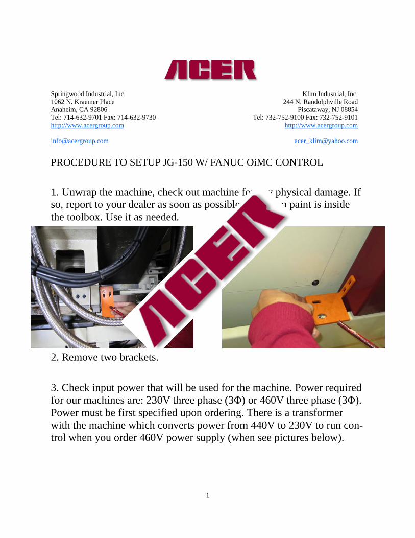
1. Unwrap the machine, check out machine for any physical damage. If so, report to your dealer as soon as possible. Touch-up paint is inside the toolbox. Use it as needed.
2. Remove two brackets.
3. Check input power that will be used for the machine. Power required for our machines are: 230V three phase (3Φ) or 460V three phase (3Φ). Power must be first specified upon ordering. There is a transformer with the machine which converts power from 440V to 230V to run con-trol when you order 460V power supply (when see pictures below).

2
4. Before powering machine, open the electric enclosing cabinet. Make sure all wires and cables are correctly wired and are tight (see picture above).
5. Turn on main power switch (picture 1). Turn on machine by pushing the green power on button (picture 2). Machine will start to load CNC software in about 10 seconds. Release emergency push button (picture 3). Push and hold the NC Ready button until the machine shows No Alarm (picture 4 & 5).
440V Primary
220V Secondary
Power Source Input Power Source Input
Open cabinet

3
When you push the NC Ready push button, the hydraulic motor will be on. Make sure that the rotation is clockwise, which means the 3 phase wiring is correct (picture 6). If the wiring is not correct, please shut down machine by reversing steps, press the red button (picture 2) and turn off main switch (picture 1). Switch any two power lines that go into the machine.
Picture 1 Picture 2
Picture 3 Picture 4
Picture 5 Picture 6

4
6. Take out support: Push MPG button (picture 7). Push the X+ button (picture 8). Press the position button, (POS) (picture 9). Turn MPG to position, remove piece of wood (picture 10 & 11).
Picture 7
Picture 8 Picture 9
Picture 10 Picture 11

5
7. Home Machine: Push home button (picture 12) , then push X+ (home) and Z+ (home) button (picture 13 & 14). Machine will move X and Z to home position.
9. Check Turret Function. Current postion is T1 (picture 15). Turn Tur-ret Select to T3 (picture 16). Push the Jog or MPG button (picture 17). Push the Turret Start button (picture 18). Turret start to rotate and stop at T3 position (picture 19).
Picture 12
Picture 14
Picture 13
Picture 16 Picture 15

6
10. Spindle checking: Insert spindle locking key. Turn to the internal locking position (picture 20) (prevent internal lock, only allow external lock). Push the foot pedal for chuck locking (picture 21). The jaw will close (picture 22). Push the Spindle On button (picture 23). The spindle start to rotate. You can also push the Spindle Off button and then push the reversing button to test rotation (picture 24). If not in the locking position, when you push the pedal, the jaw open, the warning message SPINDLE CHUCK UNCLAMP (picture 25) will show up, the spindle will not turn forward or reverse for safety. Vise versa, put the key in the external locking position (only allow the internal lock) (picture 26). Follow the procedure to test the spindle rotation.
Picture 17 Picture 18
Picture 19

7
Picture 23 Picture 22
Picture 20 Picture 21
Picture 25 Picture 24
Picture 26

8
11. Leveling the machine Precisely leveling the machine on a solid foundation. Precise leveling of the JG-150 is important to the finish of the product and the tolerance of the machine. Machine level in X and Y axes has to be within .0004/12” or better.
12. Warm-up spindle/ X, Z movement It is recommended that customers should warm up machine by slowly running spindle rpm under 600 rpm and run machine with low feed rate for 15 minutes everyday before actually cutting anything. The program can be written in the way that would help machine to “get ready” for production.
13. For auto lube pump, we recommend you to use way oil #2 or follow the manual suggestion.
9
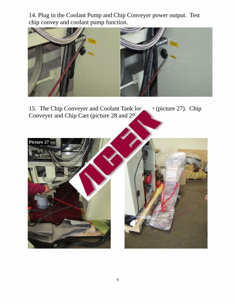
14. Plug in the Coolant Pump and Chip Conveyer power output. Test chip convey and coolant pump function.
15. The Chip Conveyer and Coolant Tank location (picture 27). Chip Conveyer and Chip Cart (picture 28 and 29).
Picture 27 Picture 28

10
16. Ready to run your CNC machine: please read through the Fanuc manual to familiarize all G code/ M code and programming on the con-trol. Call Fanuc support 888-326-8287 if you have any questions about the programming. 17. If you have any problems or questions, first call your dealer for quick questions and service. If dealer is unable to resolve your problem call Acer at 714-632- 9701 (CA) 732-752-9100 (NJ) or Fanuc at 888-326-8287 (technical support) for further assistance.
Picture 29