1 wp4 – technical issues for payload integration within the nacelle for high altitude flight...
TRANSCRIPT

1
wp4 – Technical Issues for payload integration within the Nacelle for High Altitude flight
Budapest 24/11/04
Marco Bobbio Pallavicini
Carlo Gavazzi Space SpA

2
Aerial System Engineering and Integration
Aerial System engineering and integration for designated flight mission
Nacelle structural design (SD) and mechanical integration of the PL systems
Thermal design (TD) of the system, to be operated within defined flight envelope
Design and integration of the Electrical Power System (EPS)

3
System Design – High Altitude Aerial System
All the subsystems necessary for flight mission operation will be hosted in modules within the Upper part of the Stratospheric Carrier
The Nacelle will be dedicated entirely to hosting of the two PL systems and the related Electrical Power System
Nacelle will be integrated and handled separately from the upper part of the Stratospheric Carrier up to the launch pad pre-flight display
Interfaces between the upper carrier and the nacelle are limited to a mechanical joint and three RS422 connections
Desired weight of the fully integrated and equipped nacelle is 130kg
Balloon
Balloon ATC
Cutter
Parachute
TM/TCSystem
BallastSystem
Argos GPS
Transponder
Beacon
Strobelight
RadarReflector
MechanicalLink
EquippedNacelle
15m
25m
2m
Upper part of theStratospheric Carrier
Nacelle(lower part of the Carrier)
Gas ReleaseValve

4
Structura Design – Nacelle
Aluminium mainframe
Mechanical I/F for subsystem installation (possibly adjustable for modular re-utilisation)
Four belts to connect corners of the mainframe to the joint to upper flight chain
Thermal covers for passive thermal control and protection against radiation
Protection elements for landing
5
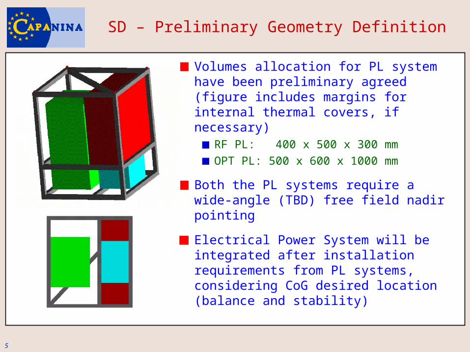
SD – Preliminary Geometry Definition
Volumes allocation for PL system have been preliminary agreed (figure includes margins for internal thermal covers, if necessary)
RF PL: 400 x 500 x 300 mmOPT PL: 500 x 600 x 1000 mm
Both the PL systems require a wide-angle (TBD) free field nadir pointing
Electrical Power System will be integrated after installation requirements from PL systems, considering CoG desired location (balance and stability)
6
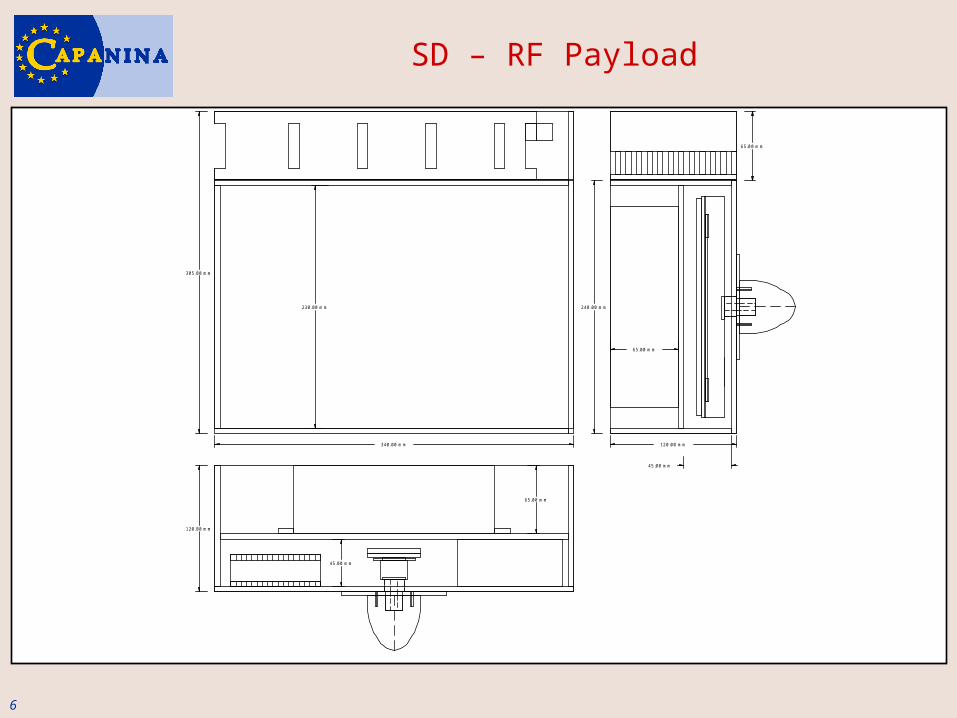
SD – RF Payload
305.00 mm
120.00 mm
230.00 mm 240.00 mm
120.00 mm340.00 mm
65.00 mm
45.00 mm
65.00 mm
65.00 mm
45.00 mm
7
Payload System Integration
Option 1 - Each of the two PL systems shall be provided as entirely included within a structural box, to be linked to the nacelle mainframe
CGS requires:Definition of mechanical I/F to the mainframeDefinition of thermal requirements and characteristics of the box as a whole
Option 2 - The elements of each PL system shall be mechanically connected one by one to the nacelle mainframe
CGS requires:Definition of mechanical I/F to the mainframe for each elementDefinition of thermal requirements and characteristics of each element

8
Thermal Design – Environmental conditions during flight mission
Each closed volume of the PL subsystem shall be provided by an appropriate venting hole, compliant with the profile of pressure differential over ascent and descent time (TBD)

9
Thermal Design - Process
1. According to preliminary design of the Aerial System, which means definition of the flight envelope, CGS shall provide nominal curves for the environmental parameters over the flight mission
2. PL integrators shall provide thermal characteristics of their systems (intended either as a whole, in case of a single integrated box for each PL, or as subsystems boxes):
Operative temperature rangeStand-by temperature rangeThermal dissipation plan over the flight mission time
PL integrators shall check the correct functioning of their systems within the mentioned environment. In case of incompliance of the PL system with the environmental profile, PL integrators shall give a feedback to CGS in terms of maximal ranges and differentials of the mentioned parameters for the correct PL system operation
CGS, shall provide solutions for the passive thermal control system
Interaction for reaching the mission feasibility, and final design

10
Electrical Power System
Electrical power will be managed by two separate systems:EPS for the Upper Aerial Carrier (not affecting the experiment)EPS for PL survival and operation (completely designed out of PL systems requirements)
The one I/F between the two systems is represented by the triple connection at standard RS422, for data communication between the PL systems and the TM/TC system onboard the Upper Aerial Carrier.
EPS for PL will consist in modular battery packs and harness for power distribution. Two main options for the configuration:
Option 1 – Common power bus (common voltage and fluctuation tolerance, according to standards)Option 2 – Dedicated Power Busses, even different for RF PL and OPT PL
Both options mentioned above require PL systems to work with Direct Current power supply
11
EPS – System Definition
EPS configuration impacts the overall Nacelle design due to:Weight Thermal matters
Information required for each of the two PL systems, for EPS preliminary design:
Voltage of the system as a whole (nominal and margins for the closed circuit)Max peak power of the system as a whole (value and elongation)Typical power need plan over the entire mission duration
Information required for each of the two PL systems, for EPS detailed design:
Voltage at the connection PL-Bus (nominal and margins for the closed circuit, fluctuation and ripple tolerance)Need for voltage monitoring and/or stabilisation

12
EPS – Batteries for High-Altitude Applications 1/3
Non-rechargeable Lithium-thionyl chloride (Li-SOCl2)
High power (drain and pulse)Wide temperature operative range (-60°C/+85°C)High sealing capability for pressure differential
13
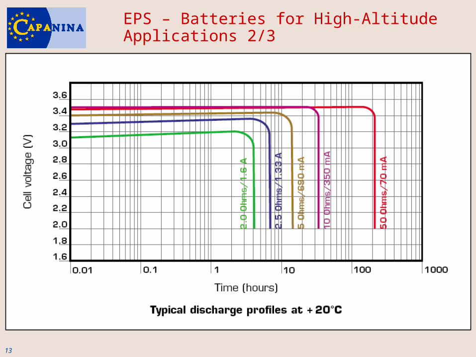
EPS – Batteries for High-Altitude Applications 2/3
14
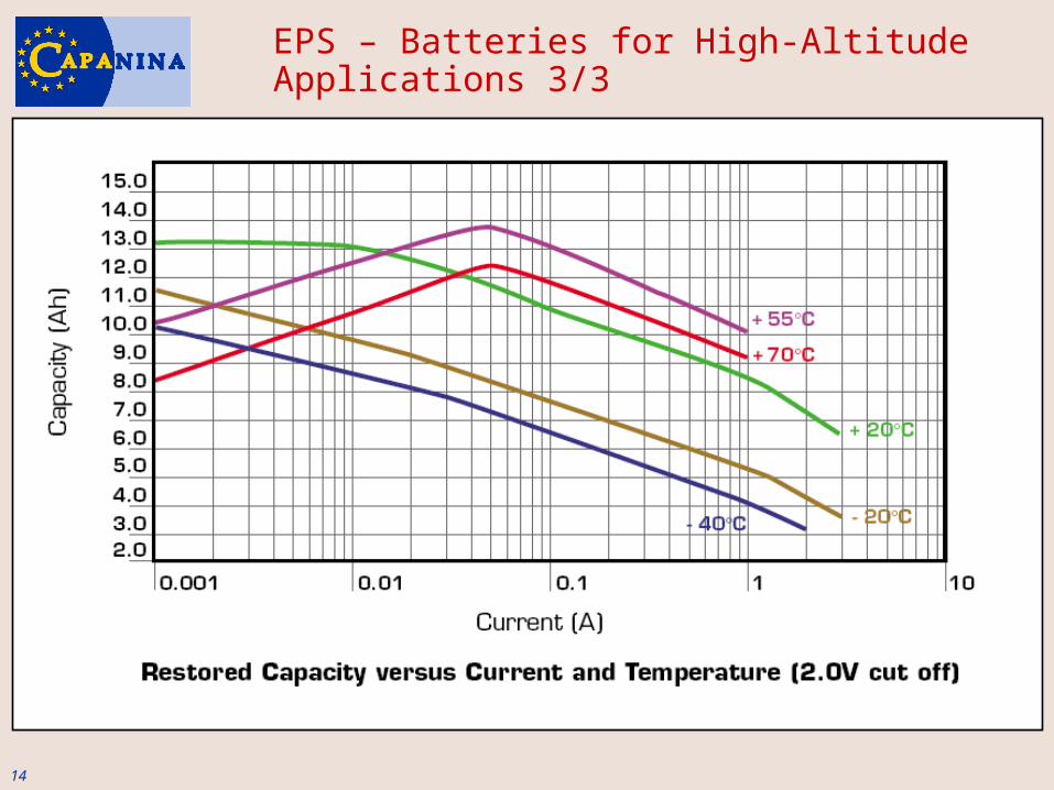
EPS – Batteries for High-Altitude Applications 3/3
15
EPS – Demo Figure
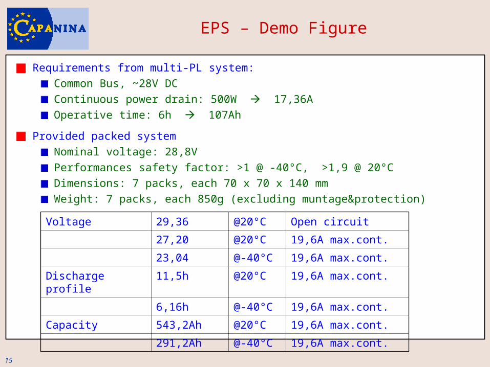
Requirements from multi-PL system:Common Bus, ~28V DCContinuous power drain: 500W 17,36AOperative time: 6h 107Ah
Provided packed systemNominal voltage: 28,8V Performances safety factor: >1 @ -40°C, >1,9 @ 20°CDimensions: 7 packs, each 70 x 70 x 140 mmWeight: 7 packs, each 850g (excluding muntage&protection)
Voltage 29,36 @20°C Open circuit
27,20 @20°C 19,6A max.cont.
23,04 @-40°C 19,6A max.cont.
Discharge profile 11,5h @20°C 19,6A max.cont.
6,16h @-40°C 19,6A max.cont.
Capacity 543,2Ah @20°C 19,6A max.cont.
291,2Ah @-40°C 19,6A max.cont.
16
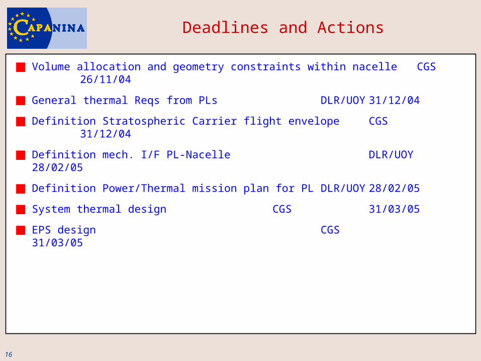
Deadlines and Actions
Volume allocation and geometry constraints within nacelle CGS26/11/04
General thermal Reqs from PLs DLR/UOY31/12/04
Definition Stratospheric Carrier flight envelope CGS31/12/04
Definition mech. I/F PL-Nacelle DLR/UOY28/02/05
Definition Power/Thermal mission plan for PLDLR/UOY28/02/05
System thermal design CGS 31/03/05
EPS design CGS31/03/05