1.0 additionalstudies (risk assessment, …€¦ · eia / ra study for installation of petroleum...
TRANSCRIPT
EIA / RA STUDY FOR INSTALLATION OF PETROLEUM STORAGE TANKS FOR STORAGE CAPACITY AUGMENTATION AT IOCL PETROLEUM TERMINAL, PHOOS MANDI, BHATINDA, PUNJAB
1
1.0 ADDITIONALSTUDIES (RISK ASSESSMENT, DISASTER MANAGEMENT PLAN,
WHAT IF ANALYSIS)
1.1 INTRODUCTION
Industrial process & activities inherently pose hazards. There may be possible hazards to
human beings, flora-fauna, all forms of property and the environment as a whole. Extreme care
is essential in handling all of them in various stages of manufacturing viz. processing, treatment
etc. The management aims at full preparedness to meet effectively the eventualities resulting
from any unfortunate occurrence of fuel hazards/accidents. Hazard analysis involves the
identification and quantification of the various hazards (unsafe conditions) that exist in the
project site. On the other hand, risk analysis deals with the identification and quantification of
risks; the Terminal equipment and personnel are exposed to, due to accident resulting from the
hazards present in the Terminal.
The main objective of the risk assessment study is that unit is MAH unit as per statutory
regulations .We attempt to determine damage due to major hazards having damage potential to
life and property and provide a scientific basis to assess safety level of the facility. The
secondary objective is to identify major risk in manufacturing process, operation, occupation and
provide control through assessment. To prepare on-site, off site, for control of hazards.
The concept of risk assessment and its industrial application has been well acclaimed since
more than a decade. A variety of major accidents have focused attention on the dangers of risk
exposure for human health and environment.
Risk analysis (RA) provides a numerical measure of the risk that a particular facility poses to the
public property and environment. It begins with the identification of potential hazardous events
and determination of impact of each event. The consequences of each event are then
calculated for numerous combinations of weather conditions and wind direction. These
consequences predications are combined to provide numerical measures of the risk for entire
facility.
Risk for a particular facility is based on the following variables:
Multiple accident outcomes
Population distribution
Site specific meteorological data
Risk analysis is a tool which helps to translate hindsight (accidents) into foresight (planning)
showing ways and means (improved engineering, procedure and supervision) to prevent the
calculated accident from happening”.
1.2 OBJECTIVE OF THE STUDY
Risk assessment is a process of estimating the likelihood of an occurrence of specific
consequences (Undesirable events) of a given severity of damage potential to life and property.
The main objective of risk assessment study is to determine the potential risks and their
likelihood for the proposed activities of the project proponent and accordingly suggesting the
mitigation measures.
EIA / RA STUDY FOR INSTALLATION OF PETROLEUM STORAGE TANKS FOR STORAGE CAPACITY AUGMENTATION AT IOCL PETROLEUM TERMINAL, PHOOS MANDI, BHATINDA, PUNJAB
2
This is achieved by the following:
To conduct systematic identification of probable hazards (Explosive /Toxic/flammable)
prevailing in the facility i.e. identification of probable failure scenarios.
Identification of specific Terminal sections which could trigger events in both process
operations and storage areas.
Identification of maximum credible loss scenario (MCLS) & worst case scenarios taking
into account the safety features to be incorporated in the Terminal design and other
parameters such as response time, trips provided etc.
To asses, the potential risks associated with identification hazards to which the Terminal,
people and outside community may be subjected to.
Consequence analysis of various hazards to determine the vulnerable zones for each
probable accident scenario.
1.2.1 Methodology
Risk Analysis is proven valuable as a management tool in assessing the overall safety
performance of the Chemical Process Industry. Although management systems such as
engineering codes, checklists, and reviews by experienced engineers have provided substantial
safety assurances, major incidents involving numerous casualties, injuries and significant
damage can occur - as illustrated by recent world-scale catastrophes. Risk Analysis techniques
provide advanced quantitative means to supplement other hazard identification, analysis,
assessment, control and management methods to identify the potential for such incidents and to
evaluate control strategies.
The underlying basis of Risk Analysis is simple in concept. It offers methods to answer the
following four questions:
1. What can go wrong?
2. What are the causes?
3. What are the consequences?
4. How likely is it?
This study tries to quantify the risks to rank them accordingly based on their severity and probability. The report shall be used to understand the significance of existing control measures and to follow the measures continuously. Wherever possible the additional risk control measures shall be adopted to bring down the risk levels.
1.2.2 Risk Assessment Procedure
Hazard identification and risk assessment involves a series of steps as follows:
Step 1: Identification of the Hazard
EIA / RA STUDY FOR INSTALLATION OF PETROLEUM STORAGE TANKS FOR STORAGE CAPACITY AUGMENTATION AT IOCL PETROLEUM TERMINAL, PHOOS MANDI, BHATINDA, PUNJAB
3
Based on consideration of factors such as the physical & chemical properties of the fluids being
handled, the arrangement of equipment, operating & maintenance procedures and process
conditions, external hazards such as third party interference, extreme environmental conditions,
and other threats shall also be considered.
Step 2: Assessment of the Risk
Arising from the hazards and consideration of its tolerability to personnel, the facility and the
environment, this involves the identification of initiating events, possible accident sequences
and likelihood of occurrence and assessment of the consequences. The acceptability of the
estimated risk must then be judged based upon criteria appropriate to the particular situation.
Step 3: Elimination or Reduction of the Risk
Where this is deemed to be necessary, this involves identifying opportunities to reduce the
likelihood and/or consequence of an accident.
Hazard Identification is a critical step in Risk Analysis. Many aids are available, including
experience, engineering codes, checklists, detailed process knowledge, equipment failure
experience, hazard index techniques, What-if Analysis, Hazard and Operability (HAZOP)
Studies, Failure Mode and Effects Analysis (FMEA), and Preliminary Hazard Analysis (PHA). In
this phase all potential incidents are identified and tabulated. Site visit and study of operations
and documents like drawings, process write-up etc. are used for hazard identification.
Assessment of Risks
The assessment of risks is based on the consequences and likelihood. Consequence
Estimation is the methodology used to determine the potential for damage or injury from specific
incidents. A single incident (e.g. catastrophic rupture or heavy leakage) can have many distinct
incident outcomes (e.g. Vapour Cloud Explosion (VCE), Pool Fire, Spilled product Fire)
Likelihood assessment is the methodology used to estimate the frequency or probability of
occurrence of an incident. Estimates may be obtained from historical incident data on failure
frequencies or from failure sequence models, such as fault trees and event trees. In this study
the historical data developed by different software models are used.
Risk Assessment combines the consequences and likelihood of all incident outcomes from all
selected incidents to provide a measure of risk. The risks of all selected incidents are
individually estimated and summed to give an overall measure of risk. Risk-reduction measures
include those to prevent incidents (i.e. reduce the likelihood of occurrence) to control incidents
(i.e. limit the extent & duration of a hazardous event) and to mitigate the effects (i.e. reduce the
consequences). Preventive measures, such as using inherently safer designs and ensuring
asset integrity, shall be used wherever practicable. In many cases, the measures to control and
mitigate hazards and risks are simple and obvious and involve modifications to conform to
standard practice. The general hierarchy of risk reducing measures is:
Prevention
Detection
Control
EIA / RA STUDY FOR INSTALLATION OF PETROLEUM STORAGE TANKS FOR STORAGE CAPACITY AUGMENTATION AT IOCL PETROLEUM TERMINAL, PHOOS MANDI, BHATINDA, PUNJAB
4
Mitigation
Emergency response
1.2.3 About Bhatinda POL, Terminal
IOCL proposed to enhance the petroleum product storage capacity of the terminal from 72,687
KL to 1,50,207 KL by constructing petroleum product storage tanks of capacities 3 X 500 KL for
ethanol, 3 X 24,000 KL for HSD and 1 X 4020 KL for MS. Also 4 additional TLF bays at Indian
Oil Corporation Ltd.(MD), Phoos mandi, Mansa Road, Bhatinda-151001 (Punjab). Petroleum
products in terminal provides coverage of only 5.0 days, which is not sufficient in the event of
major disturbances due to strikes, traffic movement, road conditions, political unrest etc,
resulting in interrupted POL product supply leading to bulk dry-out situation in terminal.
In order to maintain the continuity of POL product supply to distributors/dispensing units, IOCL
proposes to augment the storage capacity of Bhatinda POL terminal. This in-turn will also
increase the no. of days cover from 5.0 day to 10.0 days.

EIA / RA STUDY FOR INSTALLATION OF PETROLEUM STORAGE TANKS FOR STORAGE CAPACITY AUGMENTATION AT IOCL PETROLEUM TERMINAL, PHOOS MANDI, BHATINDA, PUNJAB
5
FIGURE 1.1: PLANT LAYOUT

EIA / RA STUDY FOR INSTALLATION OF PETROLEUM STORAGE TANKS FOR STORAGE CAPACITY AUGMENTATION AT IOCL PETROLEUM TERMINAL, PHOOS MANDI, BHATINDA, PUNJAB
6
1.2.3.1 Maximum Inventory of Petroleum products
Details on maximum POL product Inventory at Terminal are provided in below mentioned Table.
To analyze Maximum Credible Accident (MCA) Scenarios, following inventory of POL product
has been considered:
TABLE 1.1
DETAILS OF EXISTING POL STORAGE CAPACITY OF THE TERMINAL
T. No. Product & Class Dimensions Capacity (KL)
T-3 DHPP-A 14.0MØX10.0M HT.(CR) 1547
T-5 DHPP-A 18.0MØX12.3M HT.(CR) 3150
T-8 DHPP-A 14.0MØX10.0M HT.(CR) 1547
T-10 HSD-B 20.0MØX20.0M HT.(CR) 5937
T-11 HSD-B 20.0MØX20.0M HT.(CR) 5913
T-12 HSD-B 20.0MØX20.0M HT.(CR) 5980
T-13 SKO-B 20.0MØX20.0M HT.(CR) 5987
T-14 HSD-B 30.0MØX20.0M HT.(CR) 13516
T-15 SKO-B 12.0MØX18.0M HT.(CR) 1930
T-16 SKO-B 12.0MØX18.0M HT.(FR) 1930
T-17 MS-A 20.0MØX16.0M HT.(FR) 3930
T-18 MS-A 20.0MØX16.0M HT.(FR) 3930
T-19 MS-A 20.0MØX16.0M HT.(FR) 3930
T-20 MS-A 28.0MØX15.0M HT.(FR) 8500
T-21 MS-A 28.0MØX15.0M HT.(FR) 8500
UG-22 CLASS-A 3.0MØX10.5M LONG NOT IN USE
UG-23 HSD-B 3.0MØX10.5M LONG 70
UG-24 CLASS-B 3.0MØX10.5M LONG 70
UG-25 HSD-B 3.0MØX10.5M LONG 70
UG-26 ETHANOL-A 3.0MØX10.5M LONG U/G 70
T-27 ETHANOL-B 3.0MØX10.5M LONG(A/G) 70
UG-A MS-A 2.1MØX6.25M LONG 20
UG-B MS-A 2.1MØX6.25M LONG 20
TABLE 1.2
DETAILS OF PROPOSED POL STORAGE CAPACITY OF THE TERMINAL
Tank. No.
Product & Class Dimensions Proposed Capacity (KL)
Ethanol-A 500
Ethanol-A 500
Ethanol-A 500
HSD –B 24,000
HSD –B 24,000
HSD –B 24,000
MS -A 4,020
Total Proposed Capacity 77,520 KL
Existing Capacity 72,687 KL
Total Capacity after Expansion 1,50,207 KL
EIA / RA STUDY FOR INSTALLATION OF PETROLEUM STORAGE TANKS FOR STORAGE CAPACITY AUGMENTATION AT IOCL PETROLEUM TERMINAL, PHOOS MANDI, BHATINDA, PUNJAB
7
1.2.3.2 Dispatch of Petroleum Products
The petroleum products shall be distributed to various Industries/Petrol Pumps through truck
tanker up to capacity of 20,000 litres. On an average, 100-150 truck tanker are normally filled
and dispatched on daily basis. The loading facilities shall consist of PD metering system, batch
controllers, blending facilities for Ethanol, branded fuels etc. Vapour recovery system to be
designed & developed for handling of MS.
1.2.3.3 Truck Loading Facility (TLF) Sheds
There are two (2) nos. of TLF sheds having 2 x 8 and 1 x 4 (proposed) Tank trucks loading bays
respectively. The loading facilities are top loading for MS, HSD and SKO.
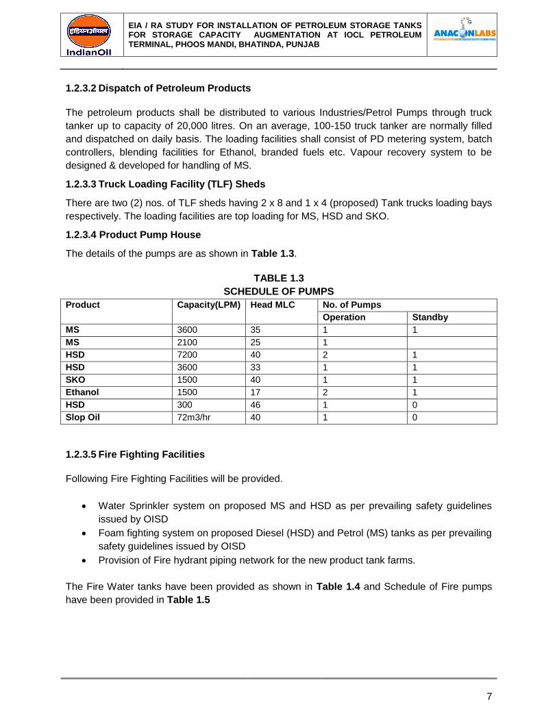
1.2.3.4 Product Pump House
The details of the pumps are as shown in Table 1.3.
TABLE 1.3
SCHEDULE OF PUMPS
Product Capacity(LPM) Head MLC No. of Pumps
Operation Standby
MS 3600 35 1 1
MS 2100 25 1
HSD 7200 40 2 1
HSD 3600 33 1 1
SKO 1500 40 1 1
Ethanol 1500 17 2 1
HSD 300 46 1 0
Slop Oil 72m3/hr 40 1 0
1.2.3.5 Fire Fighting Facilities
Following Fire Fighting Facilities will be provided.
Water Sprinkler system on proposed MS and HSD as per prevailing safety guidelines
issued by OISD
Foam fighting system on proposed Diesel (HSD) and Petrol (MS) tanks as per prevailing
safety guidelines issued by OISD
Provision of Fire hydrant piping network for the new product tank farms.
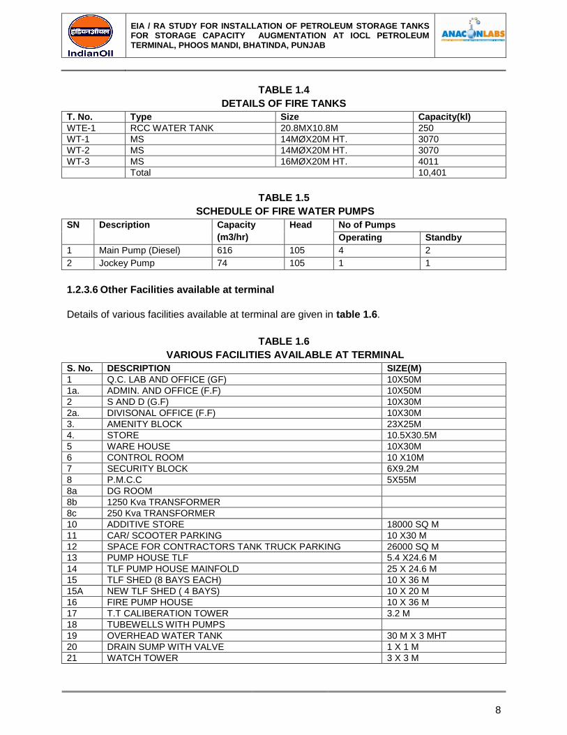
The Fire Water tanks have been provided as shown in Table 1.4 and Schedule of Fire pumps
have been provided in Table 1.5
EIA / RA STUDY FOR INSTALLATION OF PETROLEUM STORAGE TANKS FOR STORAGE CAPACITY AUGMENTATION AT IOCL PETROLEUM TERMINAL, PHOOS MANDI, BHATINDA, PUNJAB
8
TABLE 1.4
DETAILS OF FIRE TANKS
T. No. Type Size Capacity(kl)
WTE-1 RCC WATER TANK 20.8MX10.8M 250
WT-1 MS 14MØX20M HT. 3070
WT-2 MS 14MØX20M HT. 3070
WT-3 MS 16MØX20M HT. 4011
Total 10,401
TABLE 1.5
SCHEDULE OF FIRE WATER PUMPS
SN Description Capacity
(m3/hr)
Head No of Pumps
Operating Standby
1 Main Pump (Diesel) 616 105 4 2
2 Jockey Pump 74 105 1 1
1.2.3.6 Other Facilities available at terminal
Details of various facilities available at terminal are given in table 1.6.
TABLE 1.6
VARIOUS FACILITIES AVAILABLE AT TERMINAL
S. No. DESCRIPTION SIZE(M)
1 Q.C. LAB AND OFFICE (GF) 10X50M
1a. ADMIN. AND OFFICE (F.F) 10X50M
2 S AND D (G.F) 10X30M
2a. DIVISONAL OFFICE (F.F) 10X30M
3. AMENITY BLOCK 23X25M
4. STORE 10.5X30.5M
5 WARE HOUSE 10X30M
6 CONTROL ROOM 10 X10M
7 SECURITY BLOCK 6X9.2M
8 P.M.C.C 5X55M
8a DG ROOM
8b 1250 Kva TRANSFORMER
8c 250 Kva TRANSFORMER
10 ADDITIVE STORE 18000 SQ M
11 CAR/ SCOOTER PARKING 10 X30 M
12 SPACE FOR CONTRACTORS TANK TRUCK PARKING 26000 SQ M
13 PUMP HOUSE TLF 5.4 X24.6 M
14 TLF PUMP HOUSE MAINFOLD 25 X 24.6 M
15 TLF SHED (8 BAYS EACH) 10 X 36 M
15A NEW TLF SHED ( 4 BAYS) 10 X 20 M
16 FIRE PUMP HOUSE 10 X 36 M
17 T.T CALIBERATION TOWER 3.2 M
18 TUBEWELLS WITH PUMPS
19 OVERHEAD WATER TANK 30 M X 3 MHT
20 DRAIN SUMP WITH VALVE 1 X 1 M
21 WATCH TOWER 3 X 3 M

EIA / RA STUDY FOR INSTALLATION OF PETROLEUM STORAGE TANKS FOR STORAGE CAPACITY AUGMENTATION AT IOCL PETROLEUM TERMINAL, PHOOS MANDI, BHATINDA, PUNJAB
9
S. No. DESCRIPTION SIZE(M)
22 WATCH TOWER BOOTH 2 X2 M
23 T/L DECANTING PLATFORM 8 X 18 M
24 IN/OUT ( BARRIBRGATE) CARD READER AND BOOM GATES
…..
25 SECURITIES LOCKING CHECKING PLATFORM 2.0 X 1.5 M
26 SAFETY EQUIPMENT ROOM 6.5 X 4.5 M
27 T/T DECANTING PLATFORM 8.0 X 4.0 M
28 FOAM SHED 5.5 X 4.5 M
29 TLF SHED (OLD DEPOT TS) 23.5 X 6.5 M
30 HM …….
31 WATCH MAN/ LIGHT TOWER ……..
32 OFFICE BUILDING 23.5 X 6.5 M
33 FIRE HYRANT PUMP HOUSE ……..
34 SLUDGE BED 40 M X 40 M X 0.3 M
35 TT CHECKIMG PLATFORM WITH LOCK ROOM 32 M X6.6 M
36 CCTV
G G4: 4M G3: 1.2M WIDE WAUKET GATE GATE G1: 8M WIDE, G2: 6M WIDE
…….
37 TT CHECKING PLATFORM 3 M X 6 M
38 FLP LIGHT POLES (250 AND 400 W)
39 DYKE VALVES, POSITION INDICATOR 4 NOS
1.2.3.7 IDENTIFICATION OF HAZARDS AT IOCL, POL TERMINAL, BHATINDA
Petroleum Products (MS, HSD,DHPP, SKO & Ethanol) are highly inflammable due to their basic
characteristics. They are dangerous because of their intrinsic properties, i.e. flash point, ignition
energy required, heat of combustion, flammability limits, etc. In addition to such intrinsic
properties, extrinsic factors like storage & operating conditions and large storage quantity is also
considered for hazard identification. Physico-chemical properties of the petroleum products,
employed in the Installation, are given in Table 1.7.
The extent of the consequences arising from the petroleum products Installation would depend
on type & quantity of products present, mode of containment, and external factors like location,
density of population etc. In many cases, realization of hazard and its potential also depend on
prevailing meteorological conditions and availability of ignition source. Thus, most serious
consequences would arise from a large inventory of petroleum products surrounded by a
densely populated area.
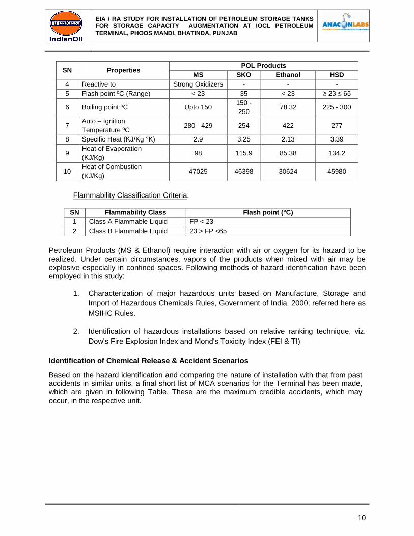
TABLE 1.7
Hazardous Properties of Petroleum Products
SN Properties POL Products
MS SKO Ethanol HSD
1 State Highly Volatile
liquid Liquid
Highly Volatile
Liquid Liquid
2 Petroleum Act/OISD
Flammability Class A B A B
3 Specific Gravity 0.72 0.76 0.79 0.81
EIA / RA STUDY FOR INSTALLATION OF PETROLEUM STORAGE TANKS FOR STORAGE CAPACITY AUGMENTATION AT IOCL PETROLEUM TERMINAL, PHOOS MANDI, BHATINDA, PUNJAB
10
SN Properties POL Products
MS SKO Ethanol HSD
4 Reactive to Strong Oxidizers - - -
5 Flash point ºC (Range) < 23 35 < 23 ≥ 23 ≤ 65
6 Boiling point ºC Upto 150 150 -
250 78.32 225 - 300
7 Auto – Ignition
Temperature ºC 280 - 429 254 422 277
8 Specific Heat (KJ/Kg °K) 2.9 3.25 2.13 3.39
9 Heat of Evaporation
(KJ/Kg) 98 115.9 85.38 134.2
10 Heat of Combustion
(KJ/Kg) 47025 46398 30624 45980
Flammability Classification Criteria:
SN Flammability Class Flash point (°C)
1 Class A Flammable Liquid FP < 23
2 Class B Flammable Liquid 23 > FP <65
Petroleum Products (MS & Ethanol) require interaction with air or oxygen for its hazard to be realized. Under certain circumstances, vapors of the products when mixed with air may be explosive especially in confined spaces. Following methods of hazard identification have been employed in this study:
1. Characterization of major hazardous units based on Manufacture, Storage and
Import of Hazardous Chemicals Rules, Government of India, 2000; referred here as
MSIHC Rules.
2. Identification of hazardous installations based on relative ranking technique, viz.
Dow's Fire Explosion Index and Mond's Toxicity Index (FEI & TI)
Identification of Chemical Release & Accident Scenarios
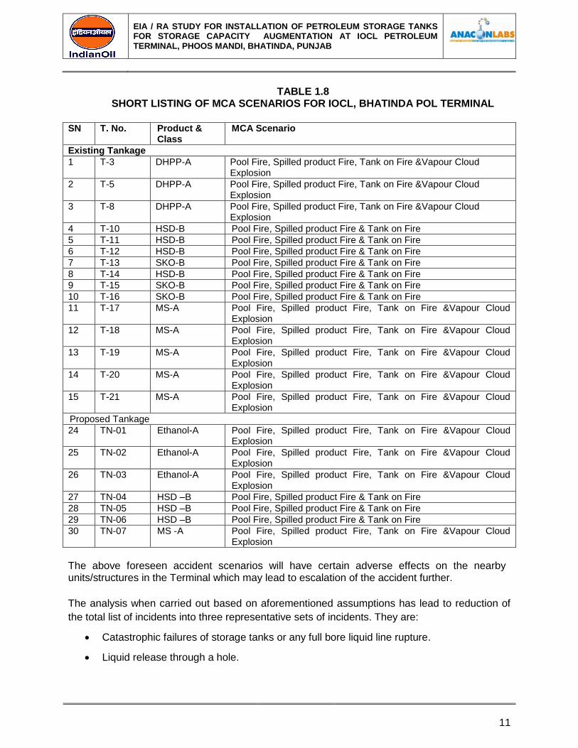
Based on the hazard identification and comparing the nature of installation with that from past accidents in similar units, a final short list of MCA scenarios for the Terminal has been made, which are given in following Table. These are the maximum credible accidents, which may occur, in the respective unit.
EIA / RA STUDY FOR INSTALLATION OF PETROLEUM STORAGE TANKS FOR STORAGE CAPACITY AUGMENTATION AT IOCL PETROLEUM TERMINAL, PHOOS MANDI, BHATINDA, PUNJAB
11
TABLE 1.8 SHORT LISTING OF MCA SCENARIOS FOR IOCL, BHATINDA POL TERMINAL
SN T. No. Product &
Class MCA Scenario
Existing Tankage
1 T-3 DHPP-A Pool Fire, Spilled product Fire, Tank on Fire &Vapour Cloud Explosion
2 T-5 DHPP-A Pool Fire, Spilled product Fire, Tank on Fire &Vapour Cloud Explosion
3 T-8 DHPP-A Pool Fire, Spilled product Fire, Tank on Fire &Vapour Cloud Explosion
4 T-10 HSD-B Pool Fire, Spilled product Fire & Tank on Fire
5 T-11 HSD-B Pool Fire, Spilled product Fire & Tank on Fire
6 T-12 HSD-B Pool Fire, Spilled product Fire & Tank on Fire
7 T-13 SKO-B Pool Fire, Spilled product Fire & Tank on Fire
8 T-14 HSD-B Pool Fire, Spilled product Fire & Tank on Fire
9 T-15 SKO-B Pool Fire, Spilled product Fire & Tank on Fire
10 T-16 SKO-B Pool Fire, Spilled product Fire & Tank on Fire
11 T-17 MS-A Pool Fire, Spilled product Fire, Tank on Fire &Vapour Cloud Explosion
12 T-18 MS-A Pool Fire, Spilled product Fire, Tank on Fire &Vapour Cloud Explosion
13 T-19 MS-A Pool Fire, Spilled product Fire, Tank on Fire &Vapour Cloud Explosion
14 T-20 MS-A Pool Fire, Spilled product Fire, Tank on Fire &Vapour Cloud Explosion
15 T-21 MS-A Pool Fire, Spilled product Fire, Tank on Fire &Vapour Cloud Explosion
Proposed Tankage
24 TN-01 Ethanol-A Pool Fire, Spilled product Fire, Tank on Fire &Vapour Cloud Explosion
25 TN-02 Ethanol-A Pool Fire, Spilled product Fire, Tank on Fire &Vapour Cloud Explosion
26 TN-03 Ethanol-A Pool Fire, Spilled product Fire, Tank on Fire &Vapour Cloud Explosion
27 TN-04 HSD –B Pool Fire, Spilled product Fire & Tank on Fire
28 TN-05 HSD –B Pool Fire, Spilled product Fire & Tank on Fire
29 TN-06 HSD –B Pool Fire, Spilled product Fire & Tank on Fire
30 TN-07 MS -A Pool Fire, Spilled product Fire, Tank on Fire &Vapour Cloud Explosion
The above foreseen accident scenarios will have certain adverse effects on the nearby units/structures in the Terminal which may lead to escalation of the accident further.
The analysis when carried out based on aforementioned assumptions has lead to reduction of
the total list of incidents into three representative sets of incidents. They are:
Catastrophic failures of storage tanks or any full bore liquid line rupture.
Liquid release through a hole.
EIA / RA STUDY FOR INSTALLATION OF PETROLEUM STORAGE TANKS FOR STORAGE CAPACITY AUGMENTATION AT IOCL PETROLEUM TERMINAL, PHOOS MANDI, BHATINDA, PUNJAB
12
Vapor release through a hole.
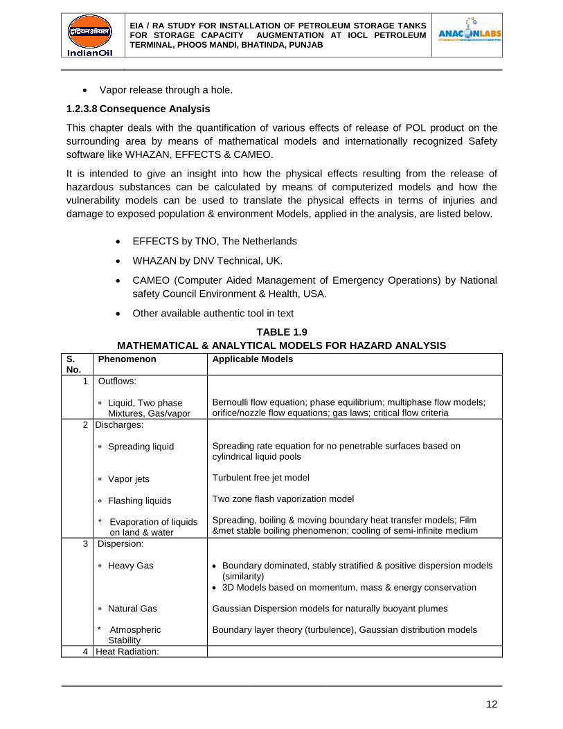
1.2.3.8 Consequence Analysis
This chapter deals with the quantification of various effects of release of POL product on the
surrounding area by means of mathematical models and internationally recognized Safety
software like WHAZAN, EFFECTS & CAMEO.
It is intended to give an insight into how the physical effects resulting from the release of
hazardous substances can be calculated by means of computerized models and how the
vulnerability models can be used to translate the physical effects in terms of injuries and
damage to exposed population & environment Models, applied in the analysis, are listed below.
EFFECTS by TNO, The Netherlands
WHAZAN by DNV Technical, UK.
CAMEO (Computer Aided Management of Emergency Operations) by National
safety Council Environment & Health, USA.
Other available authentic tool in text
TABLE 1.9
MATHEMATICAL & ANALYTICAL MODELS FOR HAZARD ANALYSIS
S. No.
Phenomenon Applicable Models
1 Ou Outflows:
Liquid, Two phase Mixtures, Gas/vapor
Bernoulli flow equation; phase equilibrium; multiphase flow models; orifice/nozzle flow equations; gas laws; critical flow criteria
2 DI Discharges:
Spreading liquid
Vapor jets
Flashing liquids * Evaporation of liquids
on land & water
Spreading rate equation for no penetrable surfaces based on cylindrical liquid pools Turbulent free jet model Two zone flash vaporization model Spreading, boiling & moving boundary heat transfer models; Film &met stable boiling phenomenon; cooling of semi-infinite medium
3 cvo Dispersion:
Heavy Gas
Natural Gas * Atmospheric Stability
Boundary dominated, stably stratified & positive dispersion models (similarity)
3D Models based on momentum, mass & energy conservation Gaussian Dispersion models for naturally buoyant plumes Boundary layer theory (turbulence), Gaussian distribution models
4 Heat Radiation:
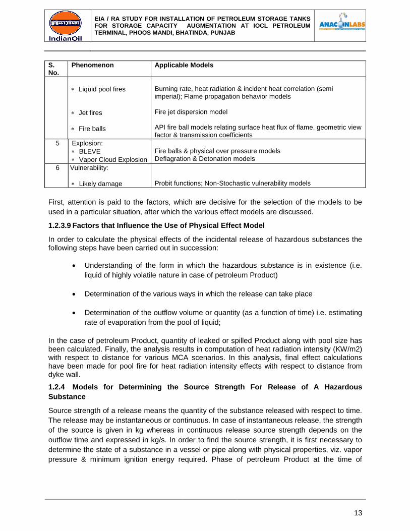
EIA / RA STUDY FOR INSTALLATION OF PETROLEUM STORAGE TANKS FOR STORAGE CAPACITY AUGMENTATION AT IOCL PETROLEUM TERMINAL, PHOOS MANDI, BHATINDA, PUNJAB
13
S. No.
Phenomenon Applicable Models
Liquid pool fires
Jet fires
Fire balls
Burning rate, heat radiation & incident heat correlation (semi imperial); Flame propagation behavior models Fire jet dispersion model API fire ball models relating surface heat flux of flame, geometric view factor & transmission coefficients
5 Explosion:
BLEVE
Vapor Cloud Explosion
Fire balls & physical over pressure models Deflagration & Detonation models
6 Vulnerability:
Likely damage
Probit functions; Non-Stochastic vulnerability models
First, attention is paid to the factors, which are decisive for the selection of the models to be
used in a particular situation, after which the various effect models are discussed.
1.2.3.9 Factors that Influence the Use of Physical Effect Model
In order to calculate the physical effects of the incidental release of hazardous substances the following steps have been carried out in succession:
Understanding of the form in which the hazardous substance is in existence (i.e.
liquid of highly volatile nature in case of petroleum Product)
Determination of the various ways in which the release can take place
Determination of the outflow volume or quantity (as a function of time) i.e. estimating
rate of evaporation from the pool of liquid;
In the case of petroleum Product, quantity of leaked or spilled Product along with pool size has been calculated. Finally, the analysis results in computation of heat radiation intensity (KW/m2) with respect to distance for various MCA scenarios. In this analysis, final effect calculations have been made for pool fire for heat radiation intensity effects with respect to distance from dyke wall.
1.2.4 Models for Determining the Source Strength For Release of A Hazardous
Substance
Source strength of a release means the quantity of the substance released with respect to time.
The release may be instantaneous or continuous. In case of instantaneous release, the strength
of the source is given in kg whereas in continuous release source strength depends on the
outflow time and expressed in kg/s. In order to find the source strength, it is first necessary to
determine the state of a substance in a vessel or pipe along with physical properties, viz. vapor
pressure & minimum ignition energy required. Phase of petroleum Product at the time of

EIA / RA STUDY FOR INSTALLATION OF PETROLEUM STORAGE TANKS FOR STORAGE CAPACITY AUGMENTATION AT IOCL PETROLEUM TERMINAL, PHOOS MANDI, BHATINDA, PUNJAB
14
accidental release is also to be determined. This may be gas, gas condensed to liquid or liquid
in equilibrium with its vapor.
1.2.4.1 Instantaneous Release
Instantaneous release will occur, for example, if a storage tank fails. Depending on the storage
conditions the following situations may occur.
(A) Instantaneous release of a Gas:
The source strength is equal to the contents of the capacity of the storage system.
(B) Instantaneous release of a Gas Condensed to Liquid:
In the case of a gas condensed to liquid, a flash off will occur due to reduction in pressure of the
liquefied gas to atmospheric pressure. The liquid will spontaneously start to boil.
(C) Instantaneous release Resulting from a BLEVE:
A BLEVE is a physical explosion, which occurs when the vapor side of a storage tank is heated
by fire e.g. a flare/torch. As a result of the heat the vapor pressure rises and the tank wall gets
weakened. At a given moment the weakened tank wall is no longer capable to withstand the
increased internal pressure and burst open. As a result of the expansion and flash off pressure
wave occurs. With flammable gases, a fireball occurs in addition to the pressure waves.
(D) Instantaneous release of a Liquid:
In the event of the instantaneous release of a liquid a pool of liquid will form. The evaporation
can be calculated on the basis of the pool.
1.2.4.2 Semi-Continuous out flow
In the case of a semi continuous outflow, it is again first of all necessary to determine whether it
is gas, a gas condensed to liquid or liquid that is flowing out. The following situations may occur
here.
(A) Gas Outflow:
The model with which the source strength is determined in the event of a gas outflow is based
on the assumption that there is no liquid in the system.
(B) Vapor Outflow:
If the outflow point is located above the liquid level, vapor outflow will occur. In the case of a gas
compressed to liquid the liquid will start boiling as a result of the drop in pressure. The source
strength of the out flowing vapor is a function of the pressure in the storage system and after the
liquid has reached the boiling point at atmospheric pressure the temperature will remain
constant.
(C) Liquid Outflow:
If the outflow point is located below the liquid level, liquid outflow will occur resulting in a flash
off. The outflow will generally be so violent that the liquid will be turned into drops as a result of
EIA / RA STUDY FOR INSTALLATION OF PETROLEUM STORAGE TANKS FOR STORAGE CAPACITY AUGMENTATION AT IOCL PETROLEUM TERMINAL, PHOOS MANDI, BHATINDA, PUNJAB
15
the intensity of the evaporation. The remaining liquid, which is cooled down to boiling point, will
start spreading on the ground and forms a pool. Evaporation will also take place from this pool,
resulting in a second semi continuous vapor source.
1.2.4.3 Models for Evaporation
In application of evaporation models, petroleum product is a case of volatile liquid. From the
pool, which has formed, evaporation will take place as a result of the heat flow from the ground
and solar radiation. The evaporation model only takes account of the heat flow from the ground
since the heat resulting from solar radiation is negligibly small compared with the former. The
evaporation rate depends on the kind of liquid and the kind of subsoil.
1.2.4.4 Models for Dispersion
The gas or vapor released either instantaneously or continuously will be spread in the
surrounding area under the influence of the atmospheric turbulence. In the case of gas
dispersion, a distinction is required to be made between neutral gas dispersion and heavy gas
dispersion.
The concentrations of the gas released in the surrounding area can be calculated by means of
these dispersion models. These concentrations are important for determining the nature of
accidents for example an explosive gas cloud formation injuries will occur in the case of toxic
gases.
Heavy Gas Dispersion Model:
If the gas density is higher than that of air due to higher molecular weight or marked cooling, it
will tend to spread in a radial direction because of gravity. This results in a "gas pool" of a
particular height and diameter. As a result of this, in contrast to a neutral gas, the gas released
may spread against the direction of the wind.
1.2.4.5 Models for Heat Load and Shock Waves
MODEL FOR FLARE/JET FIRE/TORCH
If an out-flowing gas forms a cloud with concentrations between the lower and upper explosion limit and ignition takes place, a torch occurs. A model with which the length of a torch and the thermal load for the surrounding area can be calculated, assumes an elliptic shaped torch. The volume of the flare in this model is proportional to the outflow. In order to calculate the thermal load, flare is regarded as a point source located at the center of
the flare. If an out-flowing gas forms a cloud with concentrations between the lower and
upper explosion limit and ignition takes place, a torch occurs. A model with which the length of a
torch and the thermal load for the surrounding area can be calculated, assumes an elliptic
shaped torch. The volume of the flare in this model is proportional to the outflow.
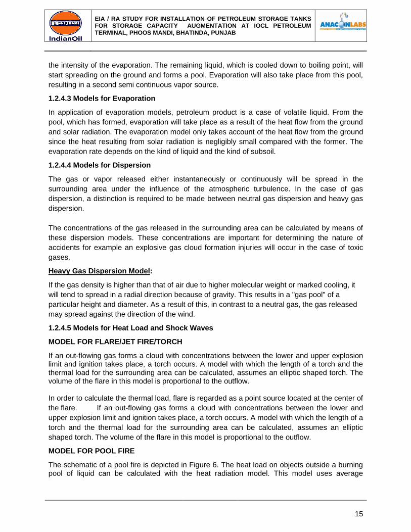
MODEL FOR POOL FIRE
The schematic of a pool fire is depicted in Figure 6. The heat load on objects outside a burning pool of liquid can be calculated with the heat radiation model. This model uses average
EIA / RA STUDY FOR INSTALLATION OF PETROLEUM STORAGE TANKS FOR STORAGE CAPACITY AUGMENTATION AT IOCL PETROLEUM TERMINAL, PHOOS MANDI, BHATINDA, PUNJAB
16
radiation intensity, which is dependent on the liquid. Account is also taken of the diameter-to-height ratio of the fire, which depends on the burning liquid. In addition, the heat load is also influenced by the following factors:
Distance from the fire
Relative humidity (water vapor has relatively high heat absorbing capacity)
The orientation i.e. horizontal/vertical of the object irradiated with respect to the fire
VULNERABILITY MODELS
Vulnerability models or dose response relations are used to determine how people are injured
by exposure to heat load or a toxic dose. Such models are designed on the basis of animal
experiments and on the basis of the analysis of injuries resulting from accidents occurred
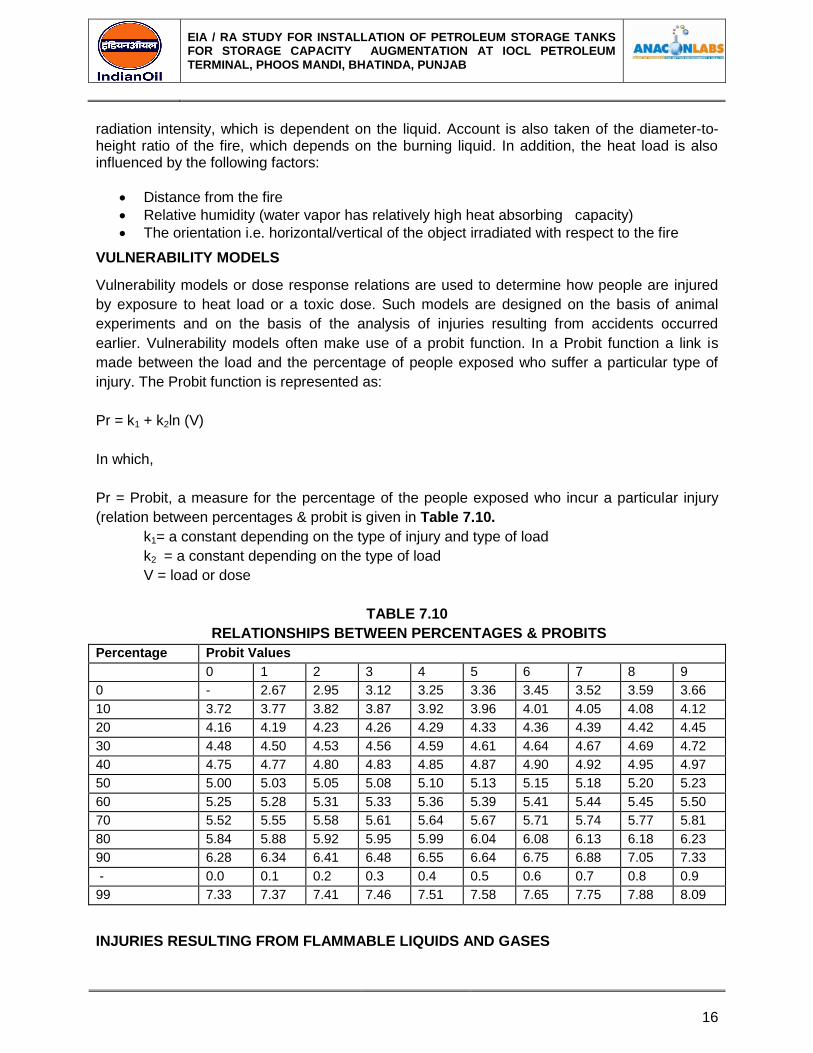
earlier. Vulnerability models often make use of a probit function. In a Probit function a link is
made between the load and the percentage of people exposed who suffer a particular type of
injury. The Probit function is represented as:
Pr = k1 + k2ln (V)
In which,
Pr = Probit, a measure for the percentage of the people exposed who incur a particular injury
(relation between percentages & probit is given in Table 7.10.
k1= a constant depending on the type of injury and type of load
k2 = a constant depending on the type of load
V = load or dose
TABLE 7.10
RELATIONSHIPS BETWEEN PERCENTAGES & PROBITS
Percentage Probit Values
0 1 2 3 4 5 6 7 8 9
0 - 2.67 2.95 3.12 3.25 3.36 3.45 3.52 3.59 3.66
10 3.72 3.77 3.82 3.87 3.92 3.96 4.01 4.05 4.08 4.12
20 4.16 4.19 4.23 4.26 4.29 4.33 4.36 4.39 4.42 4.45
30 4.48 4.50 4.53 4.56 4.59 4.61 4.64 4.67 4.69 4.72
40 4.75 4.77 4.80 4.83 4.85 4.87 4.90 4.92 4.95 4.97
50 5.00 5.03 5.05 5.08 5.10 5.13 5.15 5.18 5.20 5.23
60 5.25 5.28 5.31 5.33 5.36 5.39 5.41 5.44 5.45 5.50
70 5.52 5.55 5.58 5.61 5.64 5.67 5.71 5.74 5.77 5.81
80 5.84 5.88 5.92 5.95 5.99 6.04 6.08 6.13 6.18 6.23
90 6.28 6.34 6.41 6.48 6.55 6.64 6.75 6.88 7.05 7.33
- 0.0 0.1 0.2 0.3 0.4 0.5 0.6 0.7 0.8 0.9
99 7.33 7.37 7.41 7.46 7.51 7.58 7.65 7.75 7.88 8.09
INJURIES RESULTING FROM FLAMMABLE LIQUIDS AND GASES

EIA / RA STUDY FOR INSTALLATION OF PETROLEUM STORAGE TANKS FOR STORAGE CAPACITY AUGMENTATION AT IOCL PETROLEUM TERMINAL, PHOOS MANDI, BHATINDA, PUNJAB
17
In the case of flammable liquids and gases and immediate ignition a pool fire or a flare will occur
depending on the conditions. The injuries in this case are mainly caused by heat radiation.
DAMAGE MODELS FOR HEAT RADIATION
It is assumed that everyone inside the area covered by the fire ball, a torch, a burning pool or gas cloud will be burned to death or will asphyxiate. The following Probit functions are an example of a method, which can be used to calculate the percentage of lethality, and first-degree burns that will occur at a particular thermal load and period of exposure of an unprotected body.
Lethality: Pr = -36.83 + 2.56 ln (t.q4/3)
First degree burn symptoms: Pr = -39.83 + 3.0186 in (t.q4/3) In which, t = exposure time in seconds and;
q = thermal load W/m2
Two values have been chosen for the exposure time to heat radiation:
* 10 seconds: for exposed persons in populated area it is assumed that they will have found protection from the heat radiation e.g. from a wall, within 10 seconds
* 30 seconds: this pessimistic assumption applies if people do not run away immediately or when no protection is available
The summary of damage criteria adopted in the study based on vulnerability models and published health criteria for arriving at damage distances for the identified effects are:
Damage criteria for quantification of damage due to heat radiation have been briefed in Table
1.11.
TABLE 1.11
DAMAGE CRITERIA FOR POOL FIRE/JET FIRE
SN Likely Damage Incident Flux (KW/M2)
1. 100% Lethality & Severe damage to property Within fireball
2. 100% Lethality 37.5
3. 50% Lethality 25
4. 1% Lethality 12.5
5. Not Lethal, First degree burns 4.5
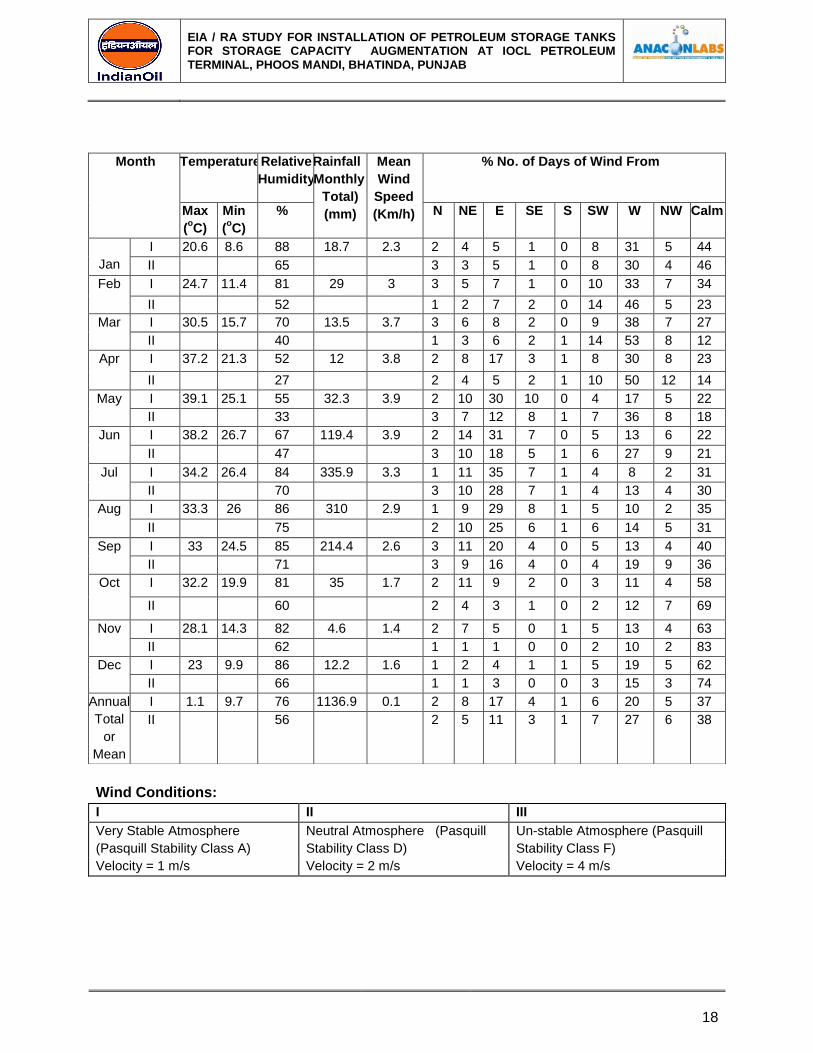
CLIMATOLOGICAL CONDITIONS
Climatological conditions have been studies for the month of December 2016at Bhatinda. Data
is taken from weather site. Form available data, it is found that, the minimum and maximum
temperatures for the month December are 8.6 °C and 39.1 °C. Relative humidity as minimum
and maximum is recorded as 27 % and 88%. Maximum wind speed and average wind flow data
given in following table.
EIA / RA STUDY FOR INSTALLATION OF PETROLEUM STORAGE TANKS FOR STORAGE CAPACITY AUGMENTATION AT IOCL PETROLEUM TERMINAL, PHOOS MANDI, BHATINDA, PUNJAB
18
Wind Conditions:
I II III
Very Stable Atmosphere
(Pasquill Stability Class A)
Neutral Atmosphere (Pasquill
Stability Class D)
Un-stable Atmosphere (Pasquill
Stability Class F)
Velocity = 1 m/s Velocity = 2 m/s Velocity = 4 m/s
Month Temperature
Relative
Humidity
Rainfall
(Monthly
Total)
(mm)
Mean
Wind
Speed
(Km/h)
% No. of Days of Wind From
Max
(oC)
Min
(oC)
% N NE E SE S SW W NW Calm
Jan
I 20.6 8.6 88 18.7 2.3 2 4 5 1 0 8 31 5 44
II 65 3 3 5 1 0 8 30 4 46
Feb I 24.7 11.4 81 29 3 3 5 7 1 0 10 33 7 34
II 52 1 2 7 2 0 14 46 5 23
Mar I 30.5 15.7 70 13.5 3.7 3 6 8 2 0 9 38 7 27
II 40 1 3 6 2 1 14 53 8 12
Apr I 37.2 21.3 52 12 3.8 2 8 17 3 1 8 30 8 23
II 27 2 4 5 2 1 10 50 12 14
May I 39.1 25.1 55 32.3 3.9 2 10 30 10 0 4 17 5 22
II 33 3 7 12 8 1 7 36 8 18
Jun I 38.2 26.7 67 119.4 3.9 2 14 31 7 0 5 13 6 22
II 47 3 10 18 5 1 6 27 9 21
Jul I 34.2 26.4 84 335.9 3.3 1 11 35 7 1 4 8 2 31
II 70 3 10 28 7 1 4 13 4 30
Aug I 33.3 26 86 310 2.9 1 9 29 8 1 5 10 2 35
II 75 2 10 25 6 1 6 14 5 31
Sep I 33 24.5
85 214.4 2.6 3 11 20 4 0 5 13 4 40
II 71 3 9 16 4 0 4 19 9 36
Oct I 32.2 19.9 81 35 1.7 2 11 9 2 0 3 11 4 58
II 60 2 4 3 1 0 2 12 7 69
Nov I 28.1 14.3 82 4.6 1.4 2 7 5 0 1 5 13 4 63
II 62 1 1 1 0 0 2 10 2 83
Dec I 23 9.9 86 12.2 1.6 1 2 4 1 1 5 19 5 62
II 66 1 1 3 0 0 3 15 3 74
Annual
Total
or
Mean
I 1.1 9.7 76 1136.9 0.1 2 8 17 4 1 6 20 5 37
II 56 2 5 11 3 1 7 27 6 38
EIA / RA STUDY FOR INSTALLATION OF PETROLEUM STORAGE TANKS FOR STORAGE CAPACITY AUGMENTATION AT IOCL PETROLEUM TERMINAL, PHOOS MANDI, BHATINDA, PUNJAB
19
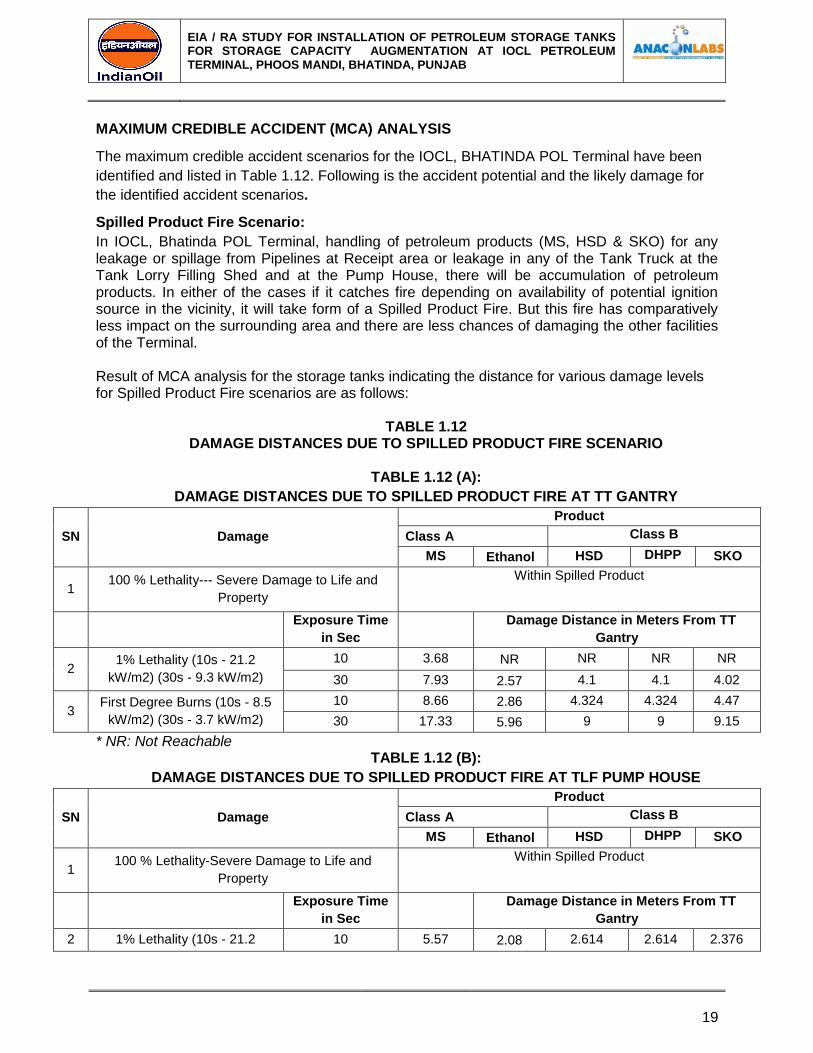
MAXIMUM CREDIBLE ACCIDENT (MCA) ANALYSIS
The maximum credible accident scenarios for the IOCL, BHATINDA POL Terminal have been
identified and listed in Table 1.12. Following is the accident potential and the likely damage for
the identified accident scenarios.
Spilled Product Fire Scenario:
In IOCL, Bhatinda POL Terminal, handling of petroleum products (MS, HSD & SKO) for any leakage or spillage from Pipelines at Receipt area or leakage in any of the Tank Truck at the Tank Lorry Filling Shed and at the Pump House, there will be accumulation of petroleum products. In either of the cases if it catches fire depending on availability of potential ignition source in the vicinity, it will take form of a Spilled Product Fire. But this fire has comparatively less impact on the surrounding area and there are less chances of damaging the other facilities of the Terminal. Result of MCA analysis for the storage tanks indicating the distance for various damage levels for Spilled Product Fire scenarios are as follows:
TABLE 1.12 DAMAGE DISTANCES DUE TO SPILLED PRODUCT FIRE SCENARIO
TABLE 1.12 (A):
DAMAGE DISTANCES DUE TO SPILLED PRODUCT FIRE AT TT GANTRY
SN Damage
Product
Class A Class B
MS Ethanol HSD DHPP SKO
1 100 % Lethality--- Severe Damage to Life and
Property
Within Spilled Product
Exposure Time
in Sec
Damage Distance in Meters From TT
Gantry
2 1% Lethality (10s - 21.2
kW/m2) (30s - 9.3 kW/m2)
10 3.68 NR NR NR NR
30 7.93 2.57 4.1 4.1 4.02
3 First Degree Burns (10s - 8.5
kW/m2) (30s - 3.7 kW/m2)
10 8.66 2.86 4.324 4.324 4.47
30 17.33 5.96 9 9 9.15
* NR: Not Reachable TABLE 1.12 (B):
DAMAGE DISTANCES DUE TO SPILLED PRODUCT FIRE AT TLF PUMP HOUSE
SN Damage
Product
Class A Class B
MS Ethanol HSD DHPP SKO
1 100 % Lethality-Severe Damage to Life and
Property
Within Spilled Product
Exposure Time
in Sec
Damage Distance in Meters From TT
Gantry
2 1% Lethality (10s - 21.2 10 5.57 2.08 2.614 2.614 2.376
EIA / RA STUDY FOR INSTALLATION OF PETROLEUM STORAGE TANKS FOR STORAGE CAPACITY AUGMENTATION AT IOCL PETROLEUM TERMINAL, PHOOS MANDI, BHATINDA, PUNJAB
20
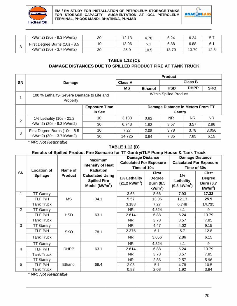
kW/m2) (30s - 9.3 kW/m2) 30 12.13 4.78 6.24 6.24 5.7
3 First Degree Burns (10s - 8.5
kW/m2) (30s - 3.7 kW/m2)
10 13.06 5.1 6.88 6.88 6.1
30 25.9 10.5 13.79 13.79 12.8
TABLE 1.12 (C):
DAMAGE DISTANCES DUE TO SPILLED PRODUCT FIRE AT TANK TRUCK
SN Damage
Product
Class A Class B
MS Ethanol HSD DHPP SKO
1 100 % Lethality- Severe Damage to Life and
Property
Within Spilled Product
Exposure Time
in Sec
Damage Distance in Meters From TT
Gantry
2 1% Lethality (10s - 21.2
kW/m2) (30s - 9.3 kW/m2)
10 3.188 0.82 NR NR NR
30 6.748 1.92 3.57 3.57 2.86
3 First Degree Burns (10s - 8.5
kW/m2) (30s - 3.7 kW/m2)
10 7.27 2.08 3.78 3.78 3.056
30 14.725 3.94 7.85 7.85 6.15
* NR: Not Reachable TABLE 1.12 (D)
Results of Spilled Product Fire Scenario for TT Gantry/TLF Pump House & Tank Truck
SN Location of
Spillage
Name of
Product
Maximum
Intensity of Heat
Radiation
Calculated Using
Spilled Fire
Model (kW/m2)
Damage Distance
Calculated For Exposure
Time of 10s
Damage Distance
Calculated For Exposure
Time of 30s
1% Lethality
(21.2 kW/m2)
First
Degree
Burn (8.5
kW/m2)
1%
Lethality
(9.3 kW/m2)
First
Degree
Burn (3.7
kW/m2)
1 TT Gantry
MS 94.1
3.68 8.66 7.93 17.33
TLF P/H 5.57 13.06 12.13 25.9
Tank Truck 3.188 7.27 6.748 14.725
2 TT Gantry
HSD 63.1
NR 4.324 4.1 9
TLF P/H 2.614 6.88 6.24 13.79
Tank Truck NR 3.78 3.57 7.85
3 TT Gantry
SKO 78.1
NR 4.47 4.02 9.15
TLF P/H 2.376 6.1 5.7 12.8
Tank Truck NR 3.056 2.86 6.15
4
TT Gantry
DHPP 63.1
NR 4.324 4.1 9
TLF P/H 2.614 6.88 6.24 13.79
Tank Truck NR 3.78 3.57 7.85
5
TT Gantry
Ethanol 68.4
NR 2.86 2.57 5.96
TLF P/H 2.08 5.1 4.78 10.5
Tank Truck 0.82 2.08 1.92 3.94
* NR: Not Reachable
EIA / RA STUDY FOR INSTALLATION OF PETROLEUM STORAGE TANKS FOR STORAGE CAPACITY AUGMENTATION AT IOCL PETROLEUM TERMINAL, PHOOS MANDI, BHATINDA, PUNJAB
21
From the observations it can be concluded that effect of spilled fire will be for a lesser distance & will not affect the Terminal properties or surrounding area. Chances of any severe lethality will be least in case of spill fire, however there can be first degree burns to the people. As soon as such spillage is observed the effort must be taken to stop the leakage and remove the spilled product. And if ignition of spilled product takes place necessary emergency procedure must be followed as soon as possible to avoid damage to other property due to secondary effect accidents.
Note: NR in above table represents that radiation of that particular heat intensity will be limited
to spilled fire area only.
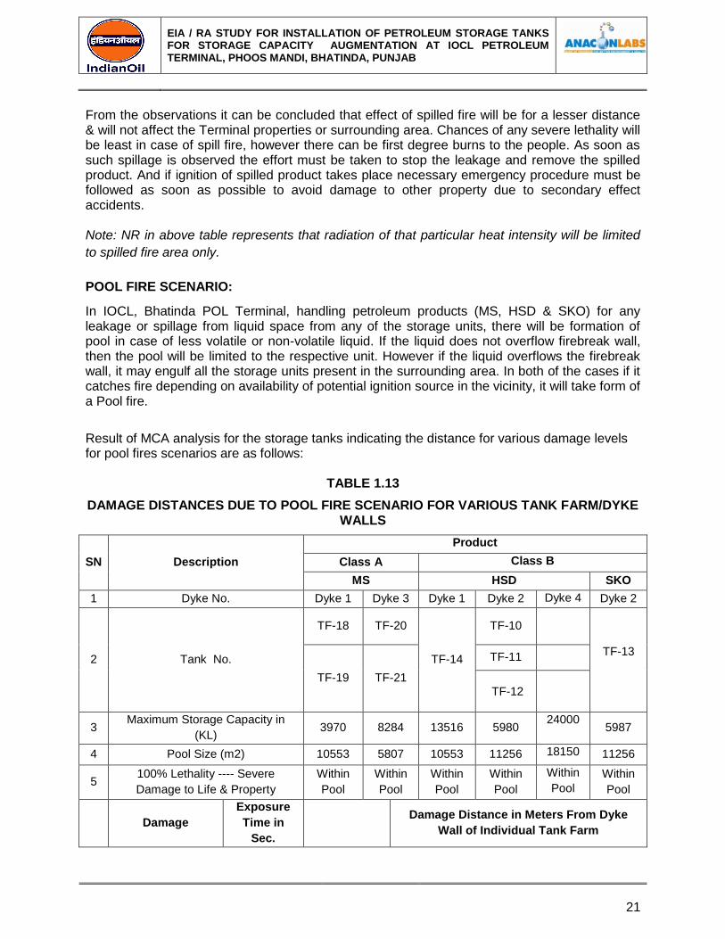
POOL FIRE SCENARIO:
In IOCL, Bhatinda POL Terminal, handling petroleum products (MS, HSD & SKO) for any leakage or spillage from liquid space from any of the storage units, there will be formation of pool in case of less volatile or non-volatile liquid. If the liquid does not overflow firebreak wall, then the pool will be limited to the respective unit. However if the liquid overflows the firebreak wall, it may engulf all the storage units present in the surrounding area. In both of the cases if it catches fire depending on availability of potential ignition source in the vicinity, it will take form of a Pool fire.
Result of MCA analysis for the storage tanks indicating the distance for various damage levels for pool fires scenarios are as follows:
TABLE 1.13
DAMAGE DISTANCES DUE TO POOL FIRE SCENARIO FOR VARIOUS TANK FARM/DYKE WALLS
SN Description
Product
Class A Class B
MS HSD SKO
1 Dyke No. Dyke 1 Dyke 3 Dyke 1 Dyke 2 Dyke 4 Dyke 2
2 Tank No.
TF-18 TF-20
TF-14
TF-10
TF-13
TF-19 TF-21
TF-11
TF-12
3 Maximum Storage Capacity in
(KL) 3970 8284 13516 5980
24000 5987
4 Pool Size (m2) 10553 5807 10553 11256 18150 11256
5 100% Lethality ---- Severe
Damage to Life & Property
Within
Pool
Within
Pool
Within
Pool
Within
Pool
Within
Pool
Within
Pool
Damage
Exposure
Time in
Sec.
Damage Distance in Meters From Dyke
Wall of Individual Tank Farm
EIA / RA STUDY FOR INSTALLATION OF PETROLEUM STORAGE TANKS FOR STORAGE CAPACITY AUGMENTATION AT IOCL PETROLEUM TERMINAL, PHOOS MANDI, BHATINDA, PUNJAB
22
SN Description
Product
Class A Class B
MS HSD SKO
6
1% Lethality (10s-
21.2 KW/m2) (30s-
9.3KW/m2)
10s 10.95 12.6 10.67 5.147 14.54 6.26
30s 22.48 26.67 21.32 12.376 28.67 15.03
7
First Degree Burns
(10s-8.5 KW/m2)
(30s-3.7 KW/m2)
10s 23.57 28.23 25.57 13.28 38.32 16.2
30s 42.96 52.64 47.77 27.55 60.10 31.98
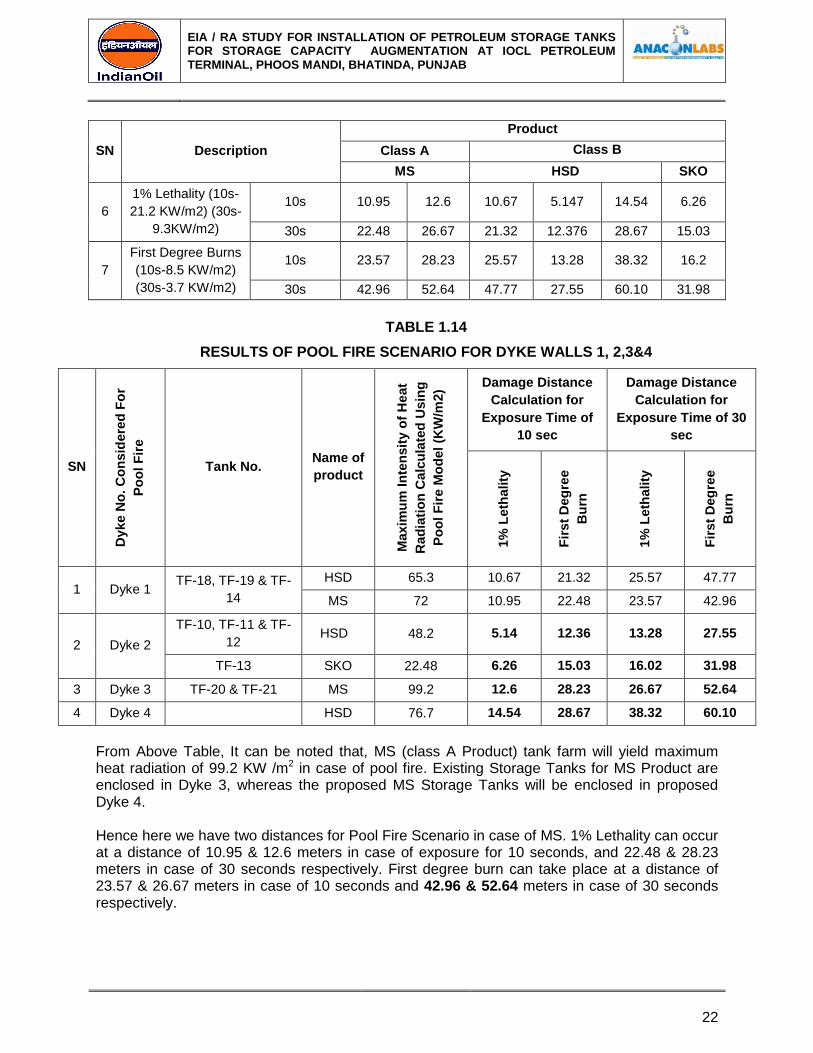
TABLE 1.14
RESULTS OF POOL FIRE SCENARIO FOR DYKE WALLS 1, 2,3&4
SN
Dyke N
o. C
on
sid
ere
d F
or
Po
ol F
ire
Tank No. Name of
product
Maxim
um
In
ten
sit
y o
f H
eat
Rad
iati
on
Ca
lcu
late
d U
sin
g
Po
ol F
ire M
od
el
(KW
/m2)
Damage Distance
Calculation for
Exposure Time of
10 sec
Damage Distance
Calculation for
Exposure Time of 30
sec
1%
Leth
ality
Fir
st
Deg
ree
Bu
rn
1%
Leth
ality
Fir
st
Deg
ree
Bu
rn
1 Dyke 1 TF-18, TF-19 & TF-
14
HSD 65.3 10.67 21.32 25.57 47.77
MS 72 10.95 22.48 23.57 42.96
2 Dyke 2
TF-10, TF-11 & TF-
12 HSD 48.2 5.14 12.36 13.28 27.55
TF-13 SKO 22.48 6.26 15.03 16.02 31.98
3 Dyke 3 TF-20 & TF-21 MS 99.2 12.6 28.23 26.67 52.64
4 Dyke 4
HSD 76.7 14.54 28.67 38.32 60.10
From Above Table, It can be noted that, MS (class A Product) tank farm will yield maximum heat radiation of 99.2 KW /m2 in case of pool fire. Existing Storage Tanks for MS Product are enclosed in Dyke 3, whereas the proposed MS Storage Tanks will be enclosed in proposed Dyke 4.
Hence here we have two distances for Pool Fire Scenario in case of MS. 1% Lethality can occur at a distance of 10.95 & 12.6 meters in case of exposure for 10 seconds, and 22.48 & 28.23 meters in case of 30 seconds respectively. First degree burn can take place at a distance of 23.57 & 26.67 meters in case of 10 seconds and 42.96 & 52.64 meters in case of 30 seconds respectively.

EIA / RA STUDY FOR INSTALLATION OF PETROLEUM STORAGE TANKS FOR STORAGE CAPACITY AUGMENTATION AT IOCL PETROLEUM TERMINAL, PHOOS MANDI, BHATINDA, PUNJAB
23
TANK ON FIRE SCENARIO:
The Tank failure scenarios were identified to assess the effect on people and property inside the Terminal area and as well as outside surrounding area.
Each tank was examined for these scenario and the results were scrutinized. The effect of fire on people and property outside and inside the Terminal is in the form of thermal radiations. A criterion was selected for deciding the maximum level of thermal radiation to which the outside population can be subjected. Thermal radiation levels from fire scenarios of each tank were worked out at various distances and their effects evaluated against the set criteria.
Thermal radiation due to tank on fire may cause various degrees of burns on exposed human bodies. Moreover their effects on piping and equipment are to be evaluated to assess their impact. Table gives type of damage due to various heat radiation intensities.
SN Radiation Load (kW/m
2) Type of Damage
1 37.5 Sufficient To Cause Damage to process Equipment
2 12.5 Minimum Energy Required For Piloted Ignition of Wood,
Molting of plastic etc.
3 4.5
Sufficient to cause pain to personnel if unable to reach
cover within 20 seconds, however blistering of skin (1st
Degree Burn) is Likely
In IOCL, BHATINDA POL Terminal each product tanks (MS, DHPP, HSD & SKO) were examined for Tank on fire scenario. The result of the above scenario is as follows:
TABLE 1.15
DAMAGE DISTANCES DUE TO TANK ON FIRE SCENARIO
T. No. Product & Class
Capacity (KL)
Damage Distance (m) From Tank Surface For
Radiation Intensity KW/m2
37.5 KW.m2 12.5 KW/m2 4.5 KW/m2
T-3 DHPP-B 1547 4.3 12.32 31.61
T-5 DHPP-B 3150 5.6 14.61 34.59
T-8 DHPP-B 1547 4.3 12.32 31.61
T-10 HSD-B 5937 5.9 16.121 39.59
T-11 HSD-B 5913 5.9 16.121 39.59
T-12 HSD-B 5980 5.9 16.121 39.59
T-13 SKO-B 5987 3.08 9.947 23.42
T-14 HSD-B 13516 14.78 24.45 42.34
T-15 SKO-B 1930 2.36 12.60 34.22
T-16 SKO-B 1930 2.36 12.60 34.22
T-17 MS-A 3930 5.75 20.87 56.10
T-18 MS-A 3930 5.75 20.87 56.10
T-19 MS-A 3930 5.75 20.87 56.10
T-20 MS-A 8500 8.75 38.62 62.03
T-21 MS-A 8500 8.75 38.62 62.03
EIA / RA STUDY FOR INSTALLATION OF PETROLEUM STORAGE TANKS FOR STORAGE CAPACITY AUGMENTATION AT IOCL PETROLEUM TERMINAL, PHOOS MANDI, BHATINDA, PUNJAB
24
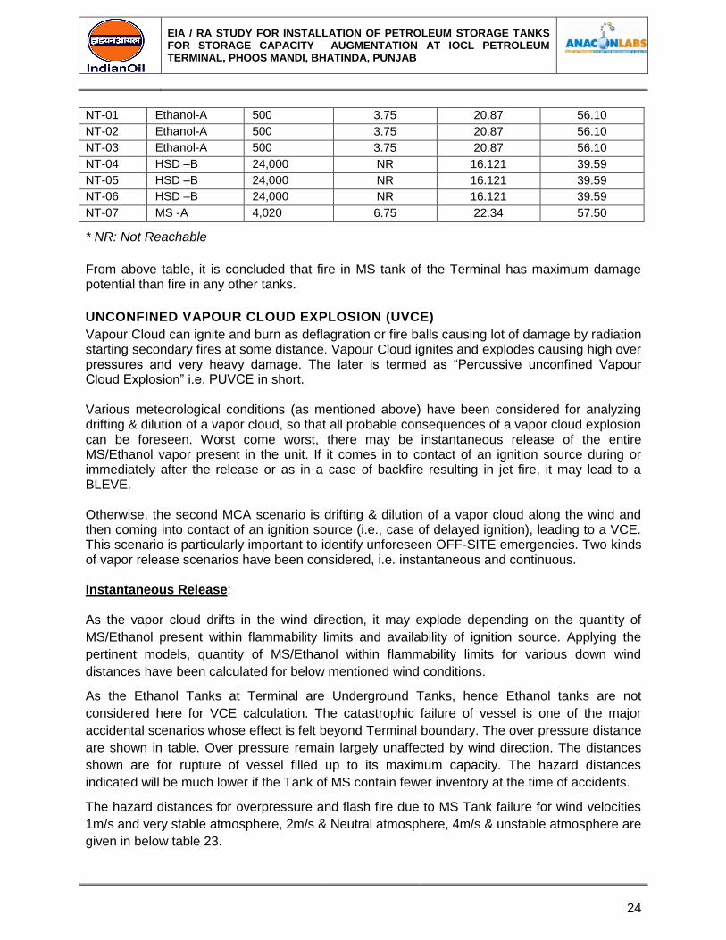
NT-01 Ethanol-A 500 3.75 20.87 56.10
NT-02 Ethanol-A 500 3.75 20.87 56.10
NT-03 Ethanol-A 500 3.75 20.87 56.10
NT-04 HSD –B 24,000 NR 16.121 39.59
NT-05 HSD –B 24,000 NR 16.121 39.59
NT-06 HSD –B 24,000 NR 16.121 39.59
NT-07 MS -A 4,020 6.75 22.34 57.50
* NR: Not Reachable
From above table, it is concluded that fire in MS tank of the Terminal has maximum damage potential than fire in any other tanks.
UNCONFINED VAPOUR CLOUD EXPLOSION (UVCE)
Vapour Cloud can ignite and burn as deflagration or fire balls causing lot of damage by radiation starting secondary fires at some distance. Vapour Cloud ignites and explodes causing high over pressures and very heavy damage. The later is termed as “Percussive unconfined Vapour Cloud Explosion” i.e. PUVCE in short.
Various meteorological conditions (as mentioned above) have been considered for analyzing drifting & dilution of a vapor cloud, so that all probable consequences of a vapor cloud explosion can be foreseen. Worst come worst, there may be instantaneous release of the entire MS/Ethanol vapor present in the unit. If it comes in to contact of an ignition source during or immediately after the release or as in a case of backfire resulting in jet fire, it may lead to a BLEVE. Otherwise, the second MCA scenario is drifting & dilution of a vapor cloud along the wind and then coming into contact of an ignition source (i.e., case of delayed ignition), leading to a VCE. This scenario is particularly important to identify unforeseen OFF-SITE emergencies. Two kinds of vapor release scenarios have been considered, i.e. instantaneous and continuous. Instantaneous Release: As the vapor cloud drifts in the wind direction, it may explode depending on the quantity of
MS/Ethanol present within flammability limits and availability of ignition source. Applying the
pertinent models, quantity of MS/Ethanol within flammability limits for various down wind
distances have been calculated for below mentioned wind conditions.
As the Ethanol Tanks at Terminal are Underground Tanks, hence Ethanol tanks are not
considered here for VCE calculation. The catastrophic failure of vessel is one of the major
accidental scenarios whose effect is felt beyond Terminal boundary. The over pressure distance
are shown in table. Over pressure remain largely unaffected by wind direction. The distances
shown are for rupture of vessel filled up to its maximum capacity. The hazard distances
indicated will be much lower if the Tank of MS contain fewer inventory at the time of accidents.
The hazard distances for overpressure and flash fire due to MS Tank failure for wind velocities
1m/s and very stable atmosphere, 2m/s & Neutral atmosphere, 4m/s & unstable atmosphere are
given in below table 23.

EIA / RA STUDY FOR INSTALLATION OF PETROLEUM STORAGE TANKS FOR STORAGE CAPACITY AUGMENTATION AT IOCL PETROLEUM TERMINAL, PHOOS MANDI, BHATINDA, PUNJAB
25
Wind Conditions:
I II III
Very Stable Atmosphere Neutral Atmosphere Unstable Atmosphere
Velocity = 1 m/s Velocity = 2 m/s Velocity = 4 m/s
For MS Storage Tank
At BHATINDA POL Terminal, class A petroleum products viz MS Ethanol are stored. VCE Scenario is studied for Both Existing & Proposed Tanks. At Terminal, MS is received through multiproduct cross-country Pipeline). As per USEPA standard (Chapter – 4: Offsite consequence analysis) for flammable liquid released into a containment area with a depth greater than 1 cm it is assumed that, the quantity that volatilizes in 10 min is involved in a vapor cloud explosion. Release of total quantity of a flammable substance in a storage tank/vessel or pipe into a vapour cloud generally would be highly unlikely. Vapour Cloud Events are also unlikely events; in an actual release, the flammable gas or vapor released to air might disperse without ignition, or it might burn instead of exploding Innocuous consequences.
TABLE 1.16 DAMAGE DISTANCES FOR VAPOUR CLOUD EXPLOSION DUE TO FAILURE OF MS
STORAGE TANK HAVING MAXIMUM STORAGE CAPACITY 8580 KL BY SYMBOLICALLY
CONSIDERING THAT CLOUD HAS COVERED 75 M DISTANCE FROM TANK/TANK TRUCK
Un
it/F
acilit
y
Ch
osen
Win
d
Co
nd
itio
n (
m/s
ec)
Qu
an
tity
Wit
hin
U
EL
& L
EL
(K
g)
Du
rati
on
of
Fir
e B
all
(seco
nd
s)
Dia
mete
r o
f C
lou
d (
m)
Maxim
um
In
ten
sit
y o
f
Heat
Rad
iati
on
at
Cen
ter
of
the C
lou
d
(KW
/m2)
Damage Distances in Meter Due to Heat Radiation in KW/m2
Severe
Damage
to Life &
Property
(100%
Lethality)
100%
Lethality
50%
Lethality
1%
Lethality
First
Degree
Burn
No
Discomfort
(37.5
KW/m2)
(25
KW/m2)
(12.5
KW/m2)
(4.5
KW/m2)
(1.6
KW/m2)
MS
Ta
nk (m
ax.
Capacity:
80
85
KL) 1 1512 5.7 70 198.4 35 68.95 87.92 117.31 197.92 331.47
2 3007 6.8 87.5 198.4 43.75 85.66 108.82 144.92 241.73 408.71
4 4847 7.7 102.2 198.4 51.1 99.61 126.22 168.01 282.29 477.28
MS
Tank
Truck
1 1911 6.1 75.5 198.4 37.75 74.18 94.49 126.05 213.62 357.63
2 3167 6.9 89 198.4 44.5 87.06 110.48 146.98 245.82 415.62
EIA / RA STUDY FOR INSTALLATION OF PETROLEUM STORAGE TANKS FOR STORAGE CAPACITY AUGMENTATION AT IOCL PETROLEUM TERMINAL, PHOOS MANDI, BHATINDA, PUNJAB
26
Un
it/F
acilit
y
Ch
osen
Win
d
Co
nd
itio
n (
m/s
ec)
Qu
an
tity
Wit
hin
U
EL
& L
EL
(K
g)
Du
rati
on
of
Fir
e B
all
(seco
nd
s)
Dia
mete
r o
f C
lou
d (
m)
Maxim
um
In
ten
sit
y o
f
Heat
Rad
iati
on
at
Cen
ter
of
the C
lou
d
(KW
/m2)
Damage Distances in Meter Due to Heat Radiation in KW/m2
Severe
Damage
to Life &
Property
(100%
Lethality)
100%
Lethality
50%
Lethality
1%
Lethality
First
Degree
Burn
No
Discomfort
(37.5
KW/m2)
(25
KW/m2)
(12.5
KW/m2)
(4.5
KW/m2)
(1.6
KW/m2)
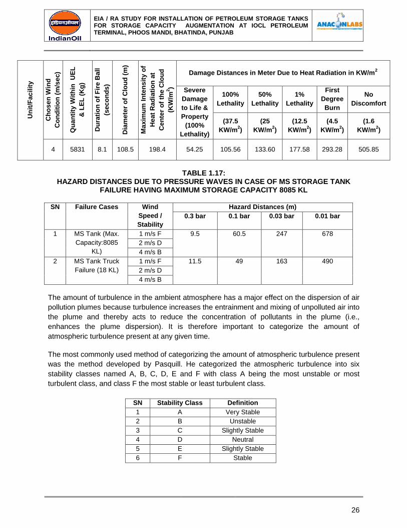
4 5831 8.1 108.5 198.4 54.25 105.56 133.60 177.58 293.28 505.85
TABLE 1.17:
HAZARD DISTANCES DUE TO PRESSURE WAVES IN CASE OF MS STORAGE TANK FAILURE HAVING MAXIMUM STORAGE CAPACITY 8085 KL
SN Failure Cases Wind
Speed /
Stability
Hazard Distances (m)
0.3 bar 0.1 bar 0.03 bar 0.01 bar
1 MS Tank (Max.
Capacity:8085
KL)
1 m/s F 9.5 60.5 247 678
2 m/s D
4 m/s B
2 MS Tank Truck
Failure (18 KL)
1 m/s F 11.5 49 163 490
2 m/s D
4 m/s B
The amount of turbulence in the ambient atmosphere has a major effect on the dispersion of air
pollution plumes because turbulence increases the entrainment and mixing of unpolluted air into
the plume and thereby acts to reduce the concentration of pollutants in the plume (i.e.,
enhances the plume dispersion). It is therefore important to categorize the amount of
atmospheric turbulence present at any given time.
The most commonly used method of categorizing the amount of atmospheric turbulence present
was the method developed by Pasquill. He categorized the atmospheric turbulence into six
stability classes named A, B, C, D, E and F with class A being the most unstable or most
turbulent class, and class F the most stable or least turbulent class.
SN Stability Class Definition
1 A Very Stable
2 B Unstable
3 C Slightly Stable
4 D Neutral
5 E Slightly Stable
6 F Stable
EIA / RA STUDY FOR INSTALLATION OF PETROLEUM STORAGE TANKS FOR STORAGE CAPACITY AUGMENTATION AT IOCL PETROLEUM TERMINAL, PHOOS MANDI, BHATINDA, PUNJAB
27
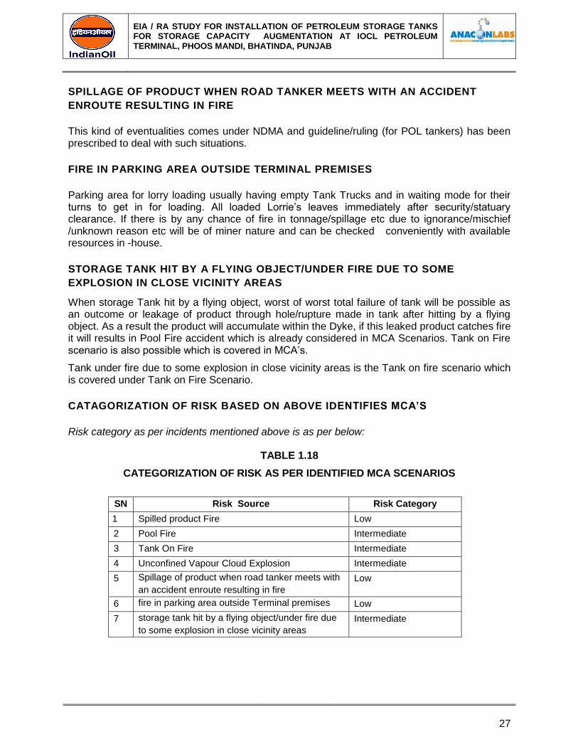
SPILLAGE OF PRODUCT WHEN ROAD TANKER MEETS WITH AN ACCIDENT
ENROUTE RESULTING IN FIRE
This kind of eventualities comes under NDMA and guideline/ruling (for POL tankers) has been prescribed to deal with such situations.
FIRE IN PARKING AREA OUTSIDE TERMINAL PREMISES
Parking area for lorry loading usually having empty Tank Trucks and in waiting mode for their turns to get in for loading. All loaded Lorrie’s leaves immediately after security/statuary clearance. If there is by any chance of fire in tonnage/spillage etc due to ignorance/mischief /unknown reason etc will be of miner nature and can be checked conveniently with available resources in -house.
STORAGE TANK HIT BY A FLYING OBJECT/UNDER FIRE DUE TO SOME
EXPLOSION IN CLOSE VICINITY AREAS
When storage Tank hit by a flying object, worst of worst total failure of tank will be possible as an outcome or leakage of product through hole/rupture made in tank after hitting by a flying object. As a result the product will accumulate within the Dyke, if this leaked product catches fire it will results in Pool Fire accident which is already considered in MCA Scenarios. Tank on Fire scenario is also possible which is covered in MCA’s.
Tank under fire due to some explosion in close vicinity areas is the Tank on fire scenario which is covered under Tank on Fire Scenario.
CATAGORIZATION OF RISK BASED ON ABOVE IDENTIFIES MCA’S
Risk category as per incidents mentioned above is as per below:
TABLE 1.18
CATEGORIZATION OF RISK AS PER IDENTIFIED MCA SCENARIOS
SN Risk Source Risk Category
1 Spilled product Fire Low
2 Pool Fire Intermediate
3 Tank On Fire Intermediate
4 Unconfined Vapour Cloud Explosion Intermediate
5 Spillage of product when road tanker meets with
an accident enroute resulting in fire
Low
6 fire in parking area outside Terminal premises Low
7 storage tank hit by a flying object/under fire due
to some explosion in close vicinity areas
Intermediate
EIA / RA STUDY FOR INSTALLATION OF PETROLEUM STORAGE TANKS FOR STORAGE CAPACITY AUGMENTATION AT IOCL PETROLEUM TERMINAL, PHOOS MANDI, BHATINDA, PUNJAB
28
CONSEQUENCES OF THE IDENTIFIED ACCIDENT SCENARIO
Possibility of fire & it’S propagation at the pol terminal, BHATINDA
Primarily there could be fire (ignition of spilled or leaked petroleum Product), flare (jet fire) or
pool fire in the Terminal. Pool fire is possible at the tank farm only whereas fire and flare are
possible at any pipeline containing MS, HSD & SKO Tank farm, Pump shed, TLF Shed and
Road Tank Truck.
Pool Fire due to HSD or SKO will not be as violent as that of MS tanks. In addition, the extent of damage for SKO/ HSD will not be more than that due to MS tank. Therefore, it is concluded that Pool Fire due to MS Tank present& Proposed Dyke would be the worst credible accident scenario as compared to pool fire in the other tanks of the Terminal.
SPILLED PRODUCT FIRE
The Product may get spilled and come in contact with a potential ignition source. In this case, it will catch fire. Extent of fire will depend on quantity of Petroleum Products (MS, HSD & SKO) released and profile of the surface on which it has been spilled. Such fire may also cause fire in the nearby flammable/combustible material, if any. This type of fire must be extinguished immediately and propagation of fire should be stopped.
JET FIRE IN POL PIPELINE/PRODUCT PUMP HOUSE/TANK FARM/TLF SHED/TT
DECANTING AREA/TANK TRUCK
If there is a leakage in the pipeline and there is availability of any ignition source, jet fire may occur. In such cases the leaked product may travel up to the ignition source and the fire may travel back to the place of leakage or the leaked Product may catch fire at the place of leakage it self. Considering the worst possible case. Such a jet fire may cause direct damage up to 10 to 35 m for a leak size of 2 to 5 cm diameter and Product being released with the head of 5 to 10 m. The flame impingement and may cause further damage.
In this case also there would be sufficient time available for the persons to come out from the affected area, if any. In such cases isolating the affected pipeline should be given first priority than extinguishing the fire. The affected equipment (being heated by the heat) should be kept cool with flow of water from monitor/hydrant.
ANALYSIS FOR PROPENSITY TOWARDS PREDICTED CONSEQUENCES
Risk of operation of any activity involving hazardous chemicals consists of the following two elements:
1. Consequences of certain unwanted event & 2. Propensity that these consequences will occur.
Propensity or likelihood of the predicted consequence for the Installation will depend upon the following items:
1. Propensity of the Terminal towards occurrence of initiating event.
2. Propensity that the designed counter measures provided in the Installation would

EIA / RA STUDY FOR INSTALLATION OF PETROLEUM STORAGE TANKS FOR STORAGE CAPACITY AUGMENTATION AT IOCL PETROLEUM TERMINAL, PHOOS MANDI, BHATINDA, PUNJAB
29
fail.
3. Propensity of certain consequence of an accident.
PROPENSITY OF THE TERMINAL TOWARDS OCCURANCE OF SUCH INITIATING
EVENT
The event could be a single component failure, for example, leakage of product from pipeline or any equipment or any tank. To evaluate this aspect for the POL terminal, Hazard and Operability Studies (HAZOP) should to be carried out.
PROPENSITY OF FAILURE OF THE DESIGNED COUNTER MEASURES
Upon occurrence of the initiating event, certain designed counter measures in the Terminal would start functioning for example isolation of the affected area from other areas by the personnel by closing the valves to restrict the quantity of escaping petroleum product; on hearing the emergency alarm the emergency team would immediately start functioning and take the necessary action to restrict or limit the damage. On the contrary these counter measures may fail also. Therefore, a lot would depend on response of the emergency team. Hazards & Operability Studies, (HAZOP) needs to be carried out to evaluate this aspect in detail.
PROPOENSITY
Any initiating event would take place first, there after the designed counter measures would attempt to limit the effects of the initiating event. Such deviations from the intended operation may lead to an accident. In reality, accident scenario and severity of the consequences will depend on type of product leaked, quantity of the product leaked, location of the incident (tank farm/pump shed/T/T plate form), availability of ignition source, response of emergency systems and emergency team, weather conditions (wind velocity & direction), etc. Further propensity of being killed or injured would also depend on the aspects like time of accident and number of people in damage area at that time.
PROBABILITY ESTIMATION FOR OCCURANCE OF MCA SCENARIO
Applying equipment failure rate data and ignition probability data probability values have been
estimated for consequences of various MCA scenarios, which are as follows:
TABLE 1.19
PROBABILITY OF OCCURRENCES OF IDENTIFIED MCA SCENARIOS
For the following accident scenarios the categorization is as follows, which is inferred on the basis of past accident analysis, information & approach provided in Green Book & Purple Book of EFFECTS, TNO:
SN Categorization Probability Range
1. Low < 10-3
To< or = 10-4
per year
2. Very Low < 10-4
To< or = 10-6
per year
3. Extremely Low < 10-6
per year on wards
The probabilities for various accident scenarios have been estimated as follows:
EIA / RA STUDY FOR INSTALLATION OF PETROLEUM STORAGE TANKS FOR STORAGE CAPACITY AUGMENTATION AT IOCL PETROLEUM TERMINAL, PHOOS MANDI, BHATINDA, PUNJAB
30
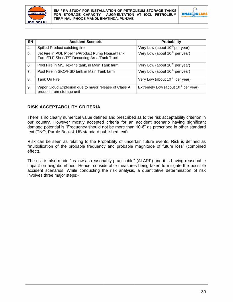
SN Accident Scenario Probability
4. Spilled Product catching fire Very Low (about 10-5
per year)
5. Jet Fire in POL Pipeline/Product Pump House/Tank Farm/TLF Shed/T/T Decanting Area/Tank Truck
Very Low (about 10-5
per year)
6. Pool Fire in MS/Hexane tank, in Main Tank farm Very Low (about 10-6
per year)
7. Pool Fire in SKO/HSD tank in Main Tank farm Very Low (about 10-6
per year)
8. Tank On Fire Very Low (about 10-7
per year)
9. Vapor Cloud Explosion due to major release of Class A product from storage unit
Extremely Low (about 10-8
per year)
RISK ACCEPTABOLITY CRITERIA
There is no clearly numerical value defined and prescribed as to the risk acceptability criterion in our country. However mostly accepted criteria for an accident scenario having significant damage potential is “Frequency should not be more than 10-6” as prescribed in other standard text (TNO, Purple Book & US standard published text). Risk can be seen as relating to the Probability of uncertain future events. Risk is defined as “multiplication of the probable frequency and probable magnitude of future loss” (combined effect).
The risk is also made "as low as reasonably practicable" (ALARP) and it is having reasonable impact on neighbourhood. Hence, considerable measures being taken to mitigate the possible accident scenarios. While conducting the risk analysis, a quantitative determination of risk involves three major steps:-
EIA / RA STUDY FOR INSTALLATION OF PETROLEUM STORAGE TANKS FOR STORAGE CAPACITY AUGMENTATION AT IOCL PETROLEUM TERMINAL, PHOOS MANDI, BHATINDA, PUNJAB
31
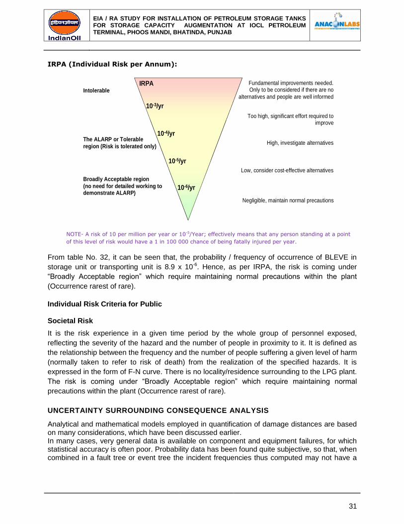
IRPA (Individual Risk per Annum):
IRPA
10-3/yr
10-4/yr
10-5/yr
10-6/yr
Intolerable
The ALARP or Tolerable
region (Risk is tolerated only)
Broadly Acceptable region
(no need for detailed working todemonstrate ALARP)
Fundamental improvements needed.Only to be considered if there are no
alternatives and people are well informed
Too high, significant effort required toimprove
High, investigate alternatives
Low, consider cost-effective alternatives
Negligible, maintain normal precautions
NOTE- A risk of 10 per million per year or 10-5/Year; effectively means that any person standing at a point
of this level of risk would have a 1 in 100 000 chance of being fatally injured per year.
From table No. 32, it can be seen that, the probability / frequency of occurrence of BLEVE in
storage unit or transporting unit is 8.9 x 10⁻⁶. Hence, as per IRPA, the risk is coming under
“Broadly Acceptable region” which require maintaining normal precautions within the plant
(Occurrence rarest of rare).
Individual Risk Criteria for Public
Societal Risk
It is the risk experience in a given time period by the whole group of personnel exposed,
reflecting the severity of the hazard and the number of people in proximity to it. It is defined as
the relationship between the frequency and the number of people suffering a given level of harm
(normally taken to refer to risk of death) from the realization of the specified hazards. It is
expressed in the form of F-N curve. There is no locality/residence surrounding to the LPG plant.
The risk is coming under “Broadly Acceptable region” which require maintaining normal
precautions within the plant (Occurrence rarest of rare).
UNCERTAINTY SURROUNDING CONSEQUENCE ANALYSIS
Analytical and mathematical models employed in quantification of damage distances are based on many considerations, which have been discussed earlier. In many cases, very general data is available on component and equipment failures, for which statistical accuracy is often poor. Probability data has been found quite subjective, so that, when combined in a fault tree or event tree the incident frequencies thus computed may not have a

EIA / RA STUDY FOR INSTALLATION OF PETROLEUM STORAGE TANKS FOR STORAGE CAPACITY AUGMENTATION AT IOCL PETROLEUM TERMINAL, PHOOS MANDI, BHATINDA, PUNJAB
32
higher confidence range. Further more, it is difficult to infer the comparison between frequencies
of two catastrophic events, for example propensity of 10-4 and 10-5 per annum.
CONCLUSION
From MCA calculations shown in above Tables, it is concluded that, for IOCL BHATINDA POL Terminal, Pool Fire accident in MS Tank of Dyke 3 have maximum damage potential than pool Fire in any other Tanks (HSD or SKO). For Tank on Fire Scenario, Fire in MS tank No. 20 &21 of Dyke-3 has maximum damage potential than fire in any other tanks.
Amongst all, Vapour Cloud Explosion in MS Tank will be the most Credible accident. Damage due to Vapour Cloud explosion in MS Tank will be more than the Damage due to Pool Fire & tank On Fire. However VCE can occur as secondary effect only and frequency of occurrence of VCE is rarest of rare.
MITIGATION/PREVENTIVE MEASURES FOR MCA SCENARIOS
In order to mitigate/prevent any minor incident from becoming a major accident following measures along with Onsite and if required Offsite Emergency (Disaster) Management Plan should be followed:
1. Spillage in tank area/pump house area/TT Gantry Area: small leakage through tank
valves/joints will take a form of spillage if not identified immediately. If this spillage gets on
contact with ignition source will take a form of fire and lead to an accident. In order to
prevent it from becoming a major accident, stop the operation immediately. Remove the
spillage with proper corrective method from that area. REMOVE SPILLED PRODUCT using
Sand or Fire Extinguishers (By Spreading Foam Solution)). Do not touch or walk through
spilled material, stop leak if possible. Use water spray to reduce vapor, do not put water
directly on leak or spill area. And if ignition of spilled product takes place necessary
emergency procedure must be followed as soon as possible to avoid damage to other
property due to secondary effect accidents. For small spillage, flush area with flooding
amounts of water.
2. Pool Fire in Dyke Area: Failure of outlet valve of tanks or any one of valve will lead to
leakage of product. This will form a pool inside dyke area if not identified immediately. This
pool if comes in contact with an ignition source will lead to an major accident. In order to
mitigate it, stop the operation immediately. Be ready will all fire fighting equipments at the
site. Start sprinkler system to cool the surrounding tanks. Immediately follow both onsite and
offsite emergency plan.
3. Tank On Fire: For preventing tank on fire, cool the surrounding tanks by means of sprinkler
system and foam system. Bring all fire fighting equipments at the site and start fighting with
fire following proper onsite emergency plan.
Unconfined Vapor Cloud Explosion: UVCE is a secondary domino effect. Vapors releasing into atmosphere are not in so much quantity that it lead to an explosion. For an ignition, a proper
EIA / RA STUDY FOR INSTALLATION OF PETROLEUM STORAGE TANKS FOR STORAGE CAPACITY AUGMENTATION AT IOCL PETROLEUM TERMINAL, PHOOS MANDI, BHATINDA, PUNJAB
33
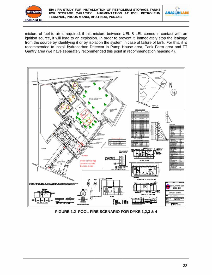
mixture of fuel to air is required, if this mixture between UEL & LEL comes in contact with an ignition source, it will lead to an explosion. In order to prevent it, immediately stop the leakage from the source by identifying it or by isolation the system in case of failure of tank. For this, it is recommended to install hydrocarbon Detector in Pump House area, Tank Farm area and TT Gantry area (we have separately recommended this point in recommendation heading 4).
FIGURE 1.2 POOL FIRE SCENARIO FOR DYKE 1,2,3 & 4
EIA / RA STUDY FOR INSTALLATION OF PETROLEUM STORAGE TANKS FOR STORAGE CAPACITY AUGMENTATION AT IOCL PETROLEUM TERMINAL, PHOOS MANDI, BHATINDA, PUNJAB
34
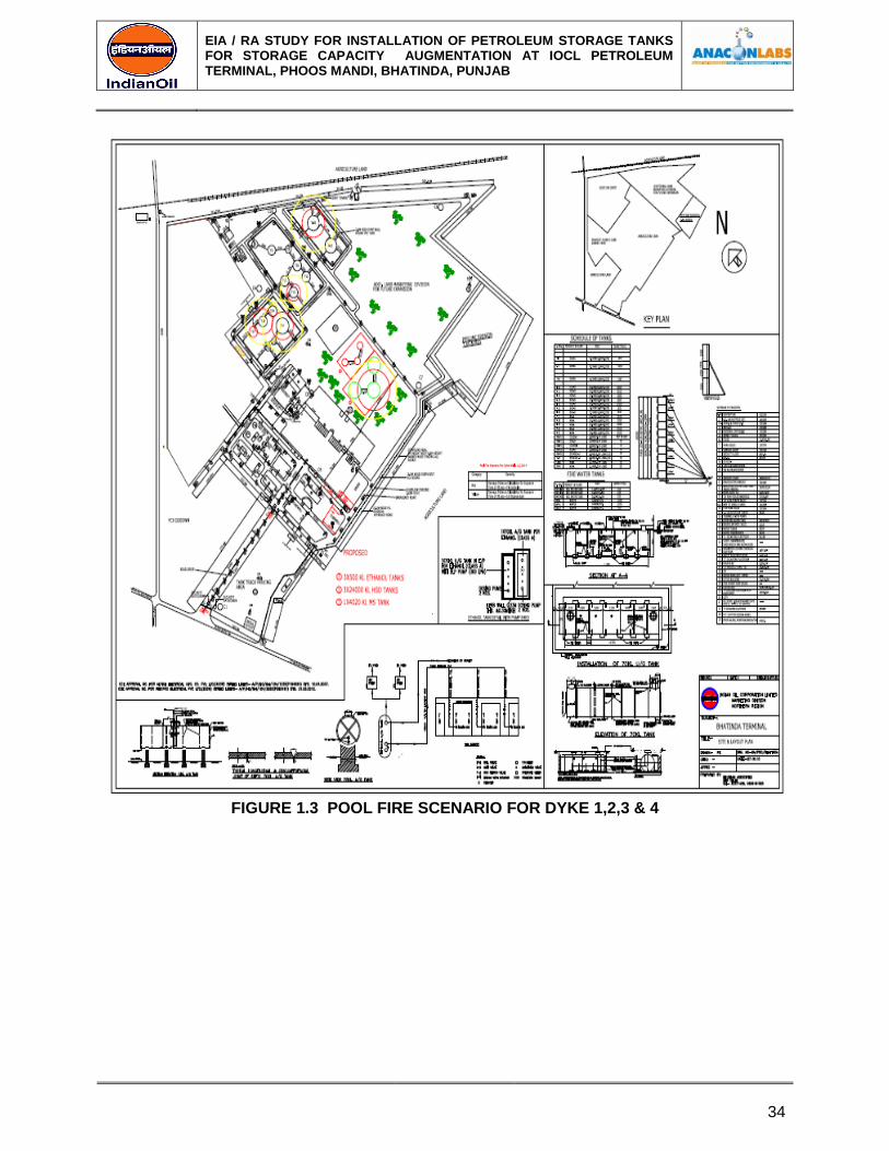
FIGURE 1.3 POOL FIRE SCENARIO FOR DYKE 1,2,3 & 4
EIA / RA STUDY FOR INSTALLATION OF PETROLEUM STORAGE TANKS FOR STORAGE CAPACITY AUGMENTATION AT IOCL PETROLEUM TERMINAL, PHOOS MANDI, BHATINDA, PUNJAB
35
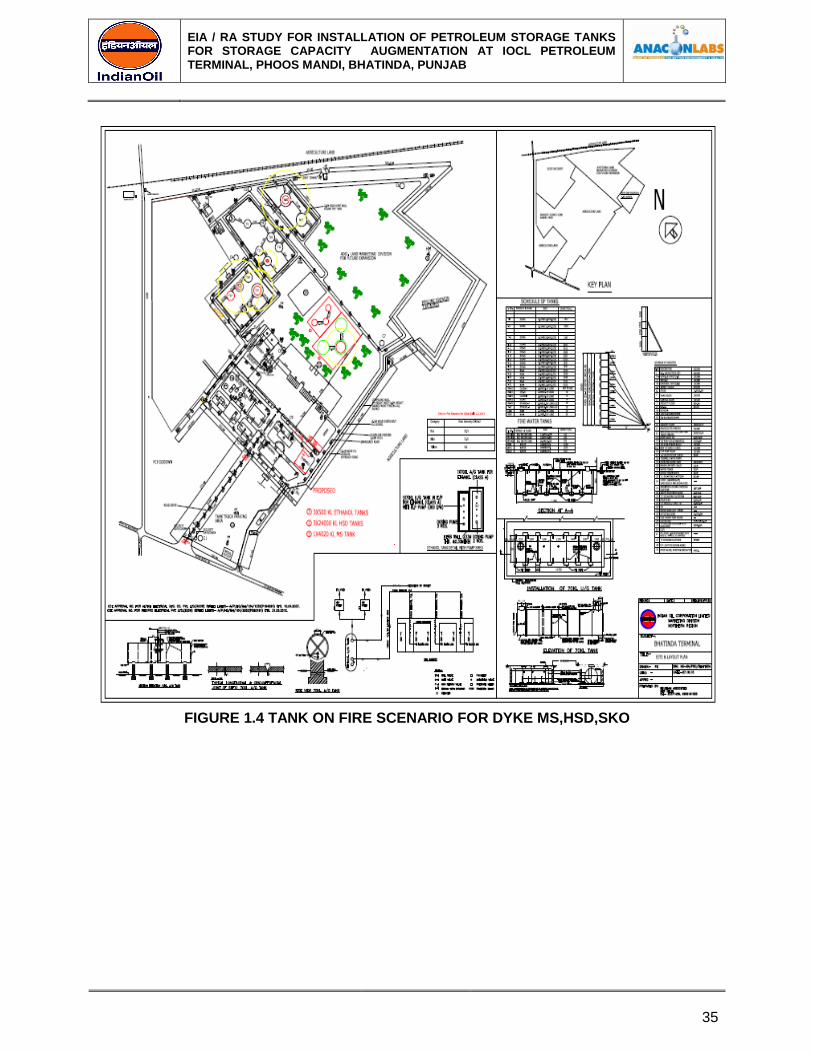
FIGURE 1.4 TANK ON FIRE SCENARIO FOR DYKE MS,HSD,SKO

EIA / RA STUDY FOR INSTALLATION OF PETROLEUM STORAGE TANKS FOR STORAGE CAPACITY AUGMENTATION AT IOCL PETROLEUM TERMINAL, PHOOS MANDI, BHATINDA, PUNJAB
36
FIGURE 1.5 VAPOUR CLOUD EXPLOSION DUE FOR MS
EIA / RA STUDY FOR INSTALLATION OF PETROLEUM STORAGE TANKS FOR STORAGE CAPACITY AUGMENTATION AT IOCL PETROLEUM TERMINAL, PHOOS MANDI, BHATINDA, PUNJAB
37
1.3 ON-SITE EMERGENCY PLAN IN STATUTORY FRAMEWORK FOR OPERATION OF
A MAJOR
1.3.1 Accident Hazard Site
The requirement of an ON-SITE EMERGENCY PLAN with detailed disaster control measures
was embodied for the first time in Section 41B (4) of THE FACTORIES (AMENDMENT) ACT,
1987 (23rd May, 1987) and came into force subsequently. The requirement is applicable to
IOCL, Bhatinda Terminal as per the First Schedule of the said Act, item 29 entitled "Highly
Flammable Liquids and Gases". Manufacture, Storage and Import of Hazardous Chemicals
Rules, 1989, notified and enforced by Union Ministry of Environment & Forests on 27th
November, 1989 under Sections 6, 8 and 25 of THE ENVIRONMENT (PROTECTION)
ACT,1986 concurrently provide the requirement of a 0N-SITE EMERGENCY PLAN, by the
occupier of accident hazard site, under Rule 13 Sub-rule 1.
1.3.2 Emergency Control Philosophy
The principal strategy of emergency control at Bhatinda POL terminal is prevention of the
identified major hazards. Since hazards can occur only in the event of loss of containment, one
of the key objectives of detail engineering, construction, commissioning and operating of the
Terminal is total and consistent quality assurance. IOCL is committed to this philosophy, so that
the objectives of prevention can have ample opportunities to mature and be realized in practice.
The second control strategy adopted for potential emergencies is surveillance of handling and
storage of hazardous substances.
Yet another control measure to be adopted is early detection of any accidental leak of
Petroleum product by trained and vigilant operating staff and activation of well-structured,
resourced and rehearsed emergency plan to intercept the incident with speed and ensure safety
of employees, assets, public and environment as a matter of priority.
1.3.3 Content of On-Site Emergency Plan Information
Mutual aid member
In the departmental "Guide of MS & IHC Rules, 1989", published in 1992, the Union Ministry of
Environment & Forests (MOEF), Government of India, specified broadly the content of an on-
site emergency plan (Page 39). This report on emergency plan has been prepared, in so far as
is practicable, in accordance with those guidelines. The guidelines were subsequently notified in
October 1994 in Official Gazette (SO-2882) of Ministry of Environment & Forests, Government
of India and are reproduced below:
Details that need to be furnished in the on-site emergency plan as per schedule- 11 of MSIHC
Rule 1989 are –
(i) Name and address of the person furnishing the information.
(ii) Key personnel of the Organization and responsibilities assigned to them in case of an
emergency.
(iii) Outside Organization if involved in assisting during an on-site emergency:
EIA / RA STUDY FOR INSTALLATION OF PETROLEUM STORAGE TANKS FOR STORAGE CAPACITY AUGMENTATION AT IOCL PETROLEUM TERMINAL, PHOOS MANDI, BHATINDA, PUNJAB
38
- Type of accidents
- Responsibility assigned.
(iv) Details of liaison arrangement between the Organizations.
(v) Information on the preliminary hazard analysis:
- Type of accidents.
- System elements or events that can lead to a major accident.
- Hazards.
- Safety relevant components.
(vi) Details about the site:
- Location of dangerous substances.
- Seat of key personnel.
- Emergency control room.
(vii) Description of hazardous chemicals at Terminal site:
- Chemicals (quantities and toxicological data).
- Transformation if any, which could occur.
- Purity of hazardous chemicals.
(viii) Likely dangers to the Terminal
(ix) Enumerate effects of -
- Stress and strain caused during normal operation.
- Fire and explosion inside the Terminal and effect, if any, of fire and explosion
outside.
(x) Details regarding
- Warning, alarm, safety and security systems.
- Alarm and hazard control plans in the line with disaster control and hazard control
planning, ensuring the necessary technical and organizational precautions.
- Reliable measuring instruments, control units and servicing of such equipments.
- Precautions in designing of the foundations and load bearing parts of the building.
- Continuous surveillance of operations.
- Maintenance and repair work according to the generally recognized rules of good
engineering practices.
(xi) Details of communication facilities available during emergency and those required for an
offsite emergency.
(xii) Details of firefighting and other facilities available and those required for an offsite
emergency.
(xiii) Details of first aid and hospital services available and its adequacy.
An outline of these details is provided in the pages following under the headings stated above,
in so far as the headings apply to Bhatinda Terminal.
1.4 KEY PERSONNEL OF ORGANIZATION AND RESPONSIBILITIES IN THE EVENT OF
AN EMERGENCY
It is to be understood that the first few minutes after the start of an incident are most vital in
prevention of escalation. Therefore the personnel available at the site on round the clock basis
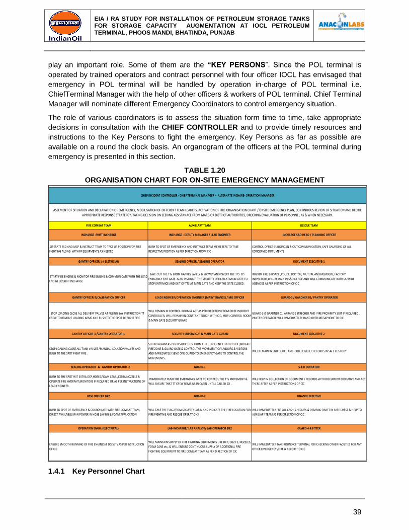
EIA / RA STUDY FOR INSTALLATION OF PETROLEUM STORAGE TANKS FOR STORAGE CAPACITY AUGMENTATION AT IOCL PETROLEUM TERMINAL, PHOOS MANDI, BHATINDA, PUNJAB
39
play an important role. Some of them are the “KEY PERSONS”. Since the POL terminal is
operated by trained operators and contract personnel with four officer IOCL has envisaged that
emergency in POL terminal will be handled by operation in-charge of POL terminal i.e.
ChiefTerminal Manager with the help of other officers & workers of POL terminal. Chief Terminal
Manager will nominate different Emergency Coordinators to control emergency situation.
The role of various coordinators is to assess the situation form time to time, take appropriate
decisions in consultation with the CHIEF CONTROLLER and to provide timely resources and
instructions to the Key Persons to fight the emergency. Key Persons as far as possible are
available on a round the clock basis. An organogram of the officers at the POL terminal during
emergency is presented in this section.
TABLE 1.20
ORGANISATION CHART FOR ON-SITE EMERGENCY MANAGEMENT
FIRE COMBAT TEAM AUXILLARY TEAM RESCUE TEAM
INCHARGE -SHIFT INCHARGE INCHARGE - DEPUTY MANAGER / LEAD ENGINEER INCHARGE S&D HEAD / PLANNING OFFICER
OPERATE ESD AND MCP & INSTRUCT TEAM TO TAKE UP POSITION FOR FIRE
FIGHTING ALONG WITH FF EQUIPMENTS AS NEEDED
RUSH TO SPOT OF EMERGENCY AND INSTRUCT TEAM MEMEBERS TO TAKE
RESPECTIVE POSITION AS PER DIRECTION FROM CIC
CONTROL OFFICE BUILDING,IN & OUT COMMUNICATION ,SAFE GAURDING OF ALL
CONCERNED DOCUMENTS
GANTRY OFFICER 1-/ ELETRICIAN SEALING OFFICER / SEALING OPERATOR DOCUMENT EXECUTIVE-1
START FIRE ENGINE & MONITOR FIRE ENGINE & COMMUNICATE WITH THE LEAD
ENGINEER/SHIFT INCHARGE
TAKE OUT THE TTs FROM GANTRY SAFELY & SLOWLY AND DIVERT THE TTS TO
EMRGENCY EXIT GATE. ALSO INSTRUCT THE SECURITY OFFICER AT MAIN GATE TO
STOP ENTRANCE AND EXIT OF TTS AT MAIN GATE AND KEEP THE GATE CLOSED.
INFORM FIRE BRIGADE ,POLICE, DOCTOR, MUTUAL AND MEMBERS, FACTORY
INSPECTORS,WILL REMAIN IN S&D OFFICE AND WILL COMMUNICATE WITH OUTSIDE
AGENCIES AS PER INSTRUCTION OF CIC
GANTRY OFFICER-2/CALIBRATION OFFICER LEAD ENGINEER/OPERATION ENGINEER (MAINTENANCE) / MIS OFFICER GUARD-3 / GARDNER 01/ PANTRY OPERATOR
STOP LOADING CLOSE ALL DELIVERY VALVES AT FILLING BAY INSTRUCTION TT
CREW TO REMOVE LOADING ARMS AND RUSH TO THE SPOT TO FIGHT FIRE
WILL REMAIN IN CONTROL ROOM & ACT AS PER DIRECTION FROM CHIEF INCIDENT
CONTROLLER, WILL REMAIN IN CONSTANT TOUCH WITH CIC, MDPL CONTROL ROOM
& MAIN GATE SECURITY GUARD
GUARD-3 & GARDNER 01: ARRANGE STRECHER AND FIRE PROXIMITY SUIT IF REQUIRED .
PANTRY OPERATOR: WILL IMMEDIATELTY HAND OVER MEGAPHONE TO CIC
GANTRY OFFICER-3 /GANTRY OPERATOR-1 SECURITY SUPERVISOR & MAIN GATE GUARD DOCUMENT EXECUTIVE-2
STOP LOADING CLOSE ALL TANK VALVES /MANUAL ISOLATION VALVES AND
RUSH TO THE SPOT FIGHT FIRE .
SOUND ALARM AS PER INSTRUCTION FROM CHIEF INCIDENT CONTROLLER ,INDICATE
FIRE ZONE & GUARD GATE & CONTROL THE MOVEMENT OF LABOURS & VISITORS
AND IMMEDIATELY SEND ONE GUARD TO EMERGENCY GATE TO CONTROL THE
MOVEMENTS.
WILL REMAIN IN S&D OFFICE AND COLLECT/KEEP RECORDS IN SAFE CUSTODY
SEALING OPERATOR & GANTRY OPERATOR -2 GUARD-1 S & D OPERATOR
RUSH TO THE SPOT WIT EXTRA DCP,HOSES,FOAM CANS ,EXTRA NOZZELS &
OPERATE FIRE HYDRANT,MONITORS IF REQUIRED OR AS PER INSTRUCTIONS OF
LEAD ENGINEER.
IMMEDIATELY RUSH THE EMERGENCY GATE TO CONTROL THE TTs MOVEMENT &
WILL ENSURE THAT TT CREW REMAINS IN CABIN UNTILL CALLED SO .
WILL HELP IN COLLECTION OF DOCUMENT / RECORDS WITH DOCUMENT EXECUTIVE AND ACT
THERE AFTER AS PER INSTRUCTIONS OF CIC
HSSE OFFICER 1&2 GUARD-2 FINANCE EXECITIVE
RUSH TO SPOT OF EMERGENCY & COORDINATE WITH FIRE COMBAT TEAM,
DIRECT AVAILABLE MAN POWER IN HOSE LAYING & FOAM APPLICATION
WILL TAKE THE FLAG FROM SECURITY CABIN AND INDICATE THE FIRE LOCATION FOR
FIRE FIGHTING AND RESCUE OPERATIONS
WILL IMMEDIATELY PUT ALL CASH, CHEQUES & DEMAND DRAFT IN SAFE CHEST & HELP TO
AUXILIARY TEAM AS PER DIRECTION OF CIC
OPERATION ENGG. (ELECTRICAL) LAB-INCHARGE/ LAB ANALYST/ LAB OPERATOR 1&2 GUARD 4 & FITTER
ENSURE SMOOTH RUNNING OF FIRE ENGINES & DG SETs AS PER INSTRUCTION
OF CIC
WILL MAINTAIN SUPPLY OF FIRE FIGHTING EQUIPMENTS LIKE DCP, CO2 FE, NOZZLES,
FOAM CANS etc, & WILL ENSURE CONTINUOUS SUPPLY OF ADDITIONAL FIRE
FIGHTING EQUIPMENT TO FIRE COMBAT TEAM AS PER DIRECTION OF CIC
WILL IMMEDIATELY TAKE ROUND OF TERMINAL FOR CHECKING OTHER FACILTIES FOR ANY
OTHER EMERGENCY /FIRE & REPORT TO CIC
FIRE ORGANISATION CHART AJMER TERMINAL - GENERAL SHIFT
ASSEMENT OF SITUATION AND DECLARATION OF EMERGENCY, MOBILISATION OF DIFFERENT TEAM LEADERS, ACTIVATION OF FIRE ORGANISATION CHART / ONSITE EMERGENCY PLAN, CONTINUOUS REVIEW OF SITUATION AND DECIDE
APPROPRIATE RESPONSE STRATERGY, TAKING DECISION ON SEEKING ASSISTANACE FROM MARG OR DISTRICT AUTHORITIES, ORDERING EVACUATION OF PERSONNEL AS & WHEN NECESSARY.
CHIEF INCIDENT CONTROLLER - CHIEF TERMINAL MANAGER - ALTERNATE INCHARE- OPERATION MANAGER
1.4.1 Key Personnel Chart
EIA / RA STUDY FOR INSTALLATION OF PETROLEUM STORAGE TANKS FOR STORAGE CAPACITY AUGMENTATION AT IOCL PETROLEUM TERMINAL, PHOOS MANDI, BHATINDA, PUNJAB
40
The senior most officers in the POL terminalis the Chief Terminal manager, who will be the
Chief Emergency Controller. In pre Emergency period he will delegate responsibility to other
officers as other Coordinators as per suitability and the job to be done by them. During
emergency, if Chief Terminal manager is not present at site, the senior most officers in the
Terminal will assume the responsibility of Chief Emergency Controller and inform Terminal
Manager to be present at site at shortest possible time.
The duties and responsibilities of Chief Controller and other Coordinator are as follows:
1.5 DUTIES & RESPONSIBILITIES OF KEY PERSONS & COORDINATORS
1.5.1 Main Incident Coordinator
For On-Site Emergency Preparedness Plan (EPP), the Location-in-Charge (Chief Terminal
manager) shall be the Main Incident Controller to coordinate the execution of the plan during an
emergency or a mock drill. He is responsible for preparation/updating of the plan, getting
approval from the District authorities/Factory Inspectorate; and its implementation in the hour of
need. His duties are:
a) Assess the magnitude of the situation and declare state of emergency. Activate EPP and
ensure its implementation.
b) Mobilize the Coordinators/Key Personnel and exercise direct operational control of
areas, other than those affected.
c) Declare danger zones and activate Emergency Control Centre.
d) Ensure calling in Mutual aid members and District emergency agencies like Fire Brigade,
Police, and Medical authorities.
e) Maintain a speculative continuous review of possible developments and assess these to
determine most probable course of events and appropriate response.
f) Inform Area Office, Head Quarters, Police, Statutory authorities, District authorities about
the magnitude of the emergency casualties and rescue operations.
g) Ensure casualties are receiving required attention and their relatives are informed.
h) Ensure accounting of personnel.
i) Issue authorized statements to Press, Radio, TV etc., regarding the emergency and its
possible impact on the surroundings.
j) Authorize procurement of emergency material.
k) Log important developments in chronological order and preserve material evidence for
investigation. Direct isolation of power supply, Terminal shutdown, and evacuation of
personnel inside the premises as deemed necessary.
l) Advise Police, District authorities regarding evacuation of public in the near
vicinity/vulnerable zone. Ensure raising the siren in EMERGENCY mode till All Clear
Signal.
m) When effects are likely to be felt outside, get in touch with District Authorities,who will
take over the management and declare "Off-Site Emergency".
n) Control rehabilitation of affected areas on cessation of emergency.
1.5.2 Administration & Communication Coordinator
EIA / RA STUDY FOR INSTALLATION OF PETROLEUM STORAGE TANKS FOR STORAGE CAPACITY AUGMENTATION AT IOCL PETROLEUM TERMINAL, PHOOS MANDI, BHATINDA, PUNJAB
41
a) Liaise with Chief and other coordinators.
b) Inform and coordinate with External agencies and Mutual aid members for agreed
assistance. Direct them on arrival to the respective coordinators.
c) In case communication means fail, send messengers to Mutual aid
members/Emergency departments. Coordinate with Police in controlling the traffic and
mob outside the premises.
d) Activate the medical Centre and mobilize medical team. Arrange ambulance and transfer
casualties to hospitals. Also coordinate with police in case of fatalities.
e) Arrange for head count at the assembly points.
f) Arrange procurement of spares for firefighting and additional medical drugs/appliances.
g) Mobilize Transport as and when required by various coordinators. Arrange to provide
spark arrestors to emergency vehicles entering the premises.
h) Monitor entry/exit of personnel in the premises. Permit only authorized personnel/
vehicles inside the premises.
i) Control and disperse crowd from the emergency site. Regulate traffic inside the location.
j) Arrange food, beverages and drinking water for all those involved in execution of EPP in
case the emergency prolongs.
k) Communicate with relatives of persons injured/involved in firefighting activities.
l) Arrange evacuation of premises as directed by Main incident controller. Coordinate with
civil authorities for evacuating public from the danger zone and arrange for refreshments
at the evacuation center.
1.5.3 Safety Coordinator
a) Ensure safe stoppage of the Operations, shut off valves on product lines, and isolation of
affected area.
b) Demarcate Danger and Safe zones by putting RED and GREEN flags.
c) Mobilize the Firefighting crew and direct the Fire Fighting operation.
d) Effectively deploy manpower, both internal and external.
e) Direct & utilize the Fire Brigade personnel.
f) Arrange the replacement of various Fire Fighting Squads with the Mutual and External
aid members on need basis.
g) Ensure/maintain sufficient pressure in the Hydrant mains.
h) Assess water level in the storage tank/reservoir and plan replenishment.
i) Monitor the requirements of Fire equipment and coordinate for procurement of spares.
j) Arrange for flood lighting of the affected areas and dewatering of the Firefighting area, if
required.
k) Arrange to remove and park the tank Lorries (Bulk & Packed) to a safer place, as
necessary.
1.6 INFORMATION ON PRELIMINARY HAZARD ANALYSIS
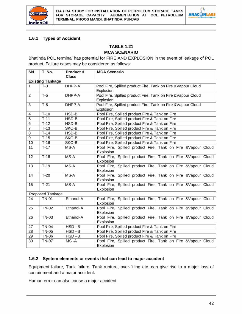
EIA / RA STUDY FOR INSTALLATION OF PETROLEUM STORAGE TANKS FOR STORAGE CAPACITY AUGMENTATION AT IOCL PETROLEUM TERMINAL, PHOOS MANDI, BHATINDA, PUNJAB
42
1.6.1 Types of Accident
TABLE 1.21
MCA SCENARIO
Bhatinda POL terminal has potential for FIRE AND EXPLOSION in the event of leakage of POL
product. Failure cases may be considered as follows:
SN T. No. Product & Class
MCA Scenario
Existing Tankage
1 T-3 DHPP-A Pool Fire, Spilled product Fire, Tank on Fire &Vapour Cloud Explosion
2 T-5 DHPP-A Pool Fire, Spilled product Fire, Tank on Fire &Vapour Cloud Explosion
3 T-8 DHPP-A Pool Fire, Spilled product Fire, Tank on Fire &Vapour Cloud Explosion
4 T-10 HSD-B Pool Fire, Spilled product Fire & Tank on Fire
5 T-11 HSD-B Pool Fire, Spilled product Fire & Tank on Fire
6 T-12 HSD-B Pool Fire, Spilled product Fire & Tank on Fire
7 T-13 SKO-B Pool Fire, Spilled product Fire & Tank on Fire
8 T-14 HSD-B Pool Fire, Spilled product Fire & Tank on Fire
9 T-15 SKO-B Pool Fire, Spilled product Fire & Tank on Fire
10 T-16 SKO-B Pool Fire, Spilled product Fire & Tank on Fire
11 T-17 MS-A Pool Fire, Spilled product Fire, Tank on Fire &Vapour Cloud Explosion
12 T-18 MS-A Pool Fire, Spilled product Fire, Tank on Fire &Vapour Cloud Explosion
13 T-19 MS-A Pool Fire, Spilled product Fire, Tank on Fire &Vapour Cloud Explosion
14 T-20 MS-A Pool Fire, Spilled product Fire, Tank on Fire &Vapour Cloud Explosion
15 T-21 MS-A Pool Fire, Spilled product Fire, Tank on Fire &Vapour Cloud Explosion
Proposed Tankage
24 TN-01 Ethanol-A Pool Fire, Spilled product Fire, Tank on Fire &Vapour Cloud Explosion
25 TN-02 Ethanol-A Pool Fire, Spilled product Fire, Tank on Fire &Vapour Cloud Explosion
26 TN-03 Ethanol-A Pool Fire, Spilled product Fire, Tank on Fire &Vapour Cloud Explosion
27 TN-04 HSD –B Pool Fire, Spilled product Fire & Tank on Fire
28 TN-05 HSD –B Pool Fire, Spilled product Fire & Tank on Fire
29 TN-06 HSD –B Pool Fire, Spilled product Fire & Tank on Fire
30 TN-07 MS -A Pool Fire, Spilled product Fire, Tank on Fire &Vapour Cloud Explosion
1.6.2 System elements or events that can lead to major accident
Equipment failure, Tank failure, Tank rupture, over-filling etc. can give rise to a major loss of
containment and a major accident.
Human error can also cause a major accident.
EIA / RA STUDY FOR INSTALLATION OF PETROLEUM STORAGE TANKS FOR STORAGE CAPACITY AUGMENTATION AT IOCL PETROLEUM TERMINAL, PHOOS MANDI, BHATINDA, PUNJAB
43
1.6.3 Hazards
Bhatinda Terminal has been characterized in the form of –
1. Spill Fire.
2. Pool Fire
3. Tank on Fire
4. Vapour Cloud Explosion.
Tank On Fire, Pool Fire and Vapor Cloud explosion are also potential hazards, which can cause
widespread damage very quickly. After consequence analysis done with the help of world
renowned SOFTWARE i.e. EFFECT it has been found that damage distances in case of non-
credible scenario extend beyond 0.5 KM.
1.6.4 Safety relevant components
The hazardous working areas of terminal should have a number of sensitive flammable gas
detectors strategically located downwind to detect any VOC and raise alarm.
These detectors shall be supplemented by manually operated break-glass type fire alarm call
points linked to electric sirens and a centralized and manned alarm annunciation panel.
All strategic areas should be fitted with 'heat-bulb' actuated medium velocity water sprinkler
systems supported by fire fighting water pumps. An extensive network of pressurized fire
hydrant system has been installed to fight fire anywhere within Terminal and to cool vessels and
structures to ensure their safety during an incident, involving incidence of dangerous heat flux.
Adequate on-site manpower shall be suitably trained and equipped to carry out fire fighting
operation efficiently. A number of diverse fire fighting media such as DCP, CO2 Fire
extinguishers etc. are strategically located in various parts of the Terminal in suitable
dispensers. Foam or any other equivalent substance should be used in adequate measure to
cut-down evaporation from a pool and thus inhibit fire and formation of a flammable gas cloud.
Fire and explosion inside the Terminal and effect, if any, outside
Based on Consequence Analysis it has been found that the effect distances and areas of fire
and explosion reach more than 0.5 Km in case of non-credible failure scenario like VCE in and
pressure waves and 0.3 Km from tank.
1.7 DETAILS REGARDING WARNING ALARM, SAFETY & SECURITY SYSTEMS
One 3.0 Km range Electric Siren, Six Hand Sirens have been installed to announce the on-set
of an emergency. This can be triggered manually as and when a gas leak is detected.
1.7.1 Other Alarms
High-level alarms are to be provided in the storage tanks to provide a warning to the filling
operator if more than safe filling heights.
a) Precautions in designing of the foundation & load bearing parts of the building
EIA / RA STUDY FOR INSTALLATION OF PETROLEUM STORAGE TANKS FOR STORAGE CAPACITY AUGMENTATION AT IOCL PETROLEUM TERMINAL, PHOOS MANDI, BHATINDA, PUNJAB
44
Foundations and load bearing parts are designed by competent Engineering Agency as per
approved Codes of Practice and take into account operational loads and extremes of storm,
lighting and flood. All storage tanks are electrically grounded to a network of earth stations with
buried electrodes.
b) Continuous surveillance operations
The POL storage and handling operations will be continually under surveillance to prevent major
incidents and to intercept one at the developing stage. Leakage condition should be
continuously scanned by the gas detectors to be provided at vulnerable places.
c) Maintenance and repair work according to the generally recognized rules of good
engineering practice
Preventive and breakdown maintenance and repair work are be carried out under the
supervision of Terminal Manager / Dy. Manager. Equipment and criticality oriented inspection,
periodic non-destructive testing and maintenance schedules are prepared with specialist inputs
from within terminal, OISD and equipment manufacturers.
Details of communication facilities provided for emergency
(i) One 3.0 Km range Electric Siren to announce nature of emergency.
(ii) Six hand sirens are also provided.
(iii) An interTerminal paging system in Non-flame proof areas and as well as in flameproof
areas are provided for normal and emergency announcements and communication with
master control in the control room.
(iv) For inter-location communications and requisite number of P&T telephones including tie
lines and hot lines for communication with district emergency services, authorities,
hospitals etc.
(v) The interTerminal paging and public address system are having the following features-
- All call with answer back
- Group call with answer back
- Interfacing with walkie talkies
- Field call stations
(vi) Walkie Talkies and mobile phones are deployed for mobile-to-mobile and mobile-to-
stationary communication.
(vii) A broad communication diagram outlining interactions between various role players
1.7.2 Details of Fire Fighting & Other Facilities Available
The Bhatinda, POL terminal is provided with following firefighting system & other preventive
measures:
1.7.3 Fire Fighting Facilities
Following Fire Fighting Facilities will be provided.
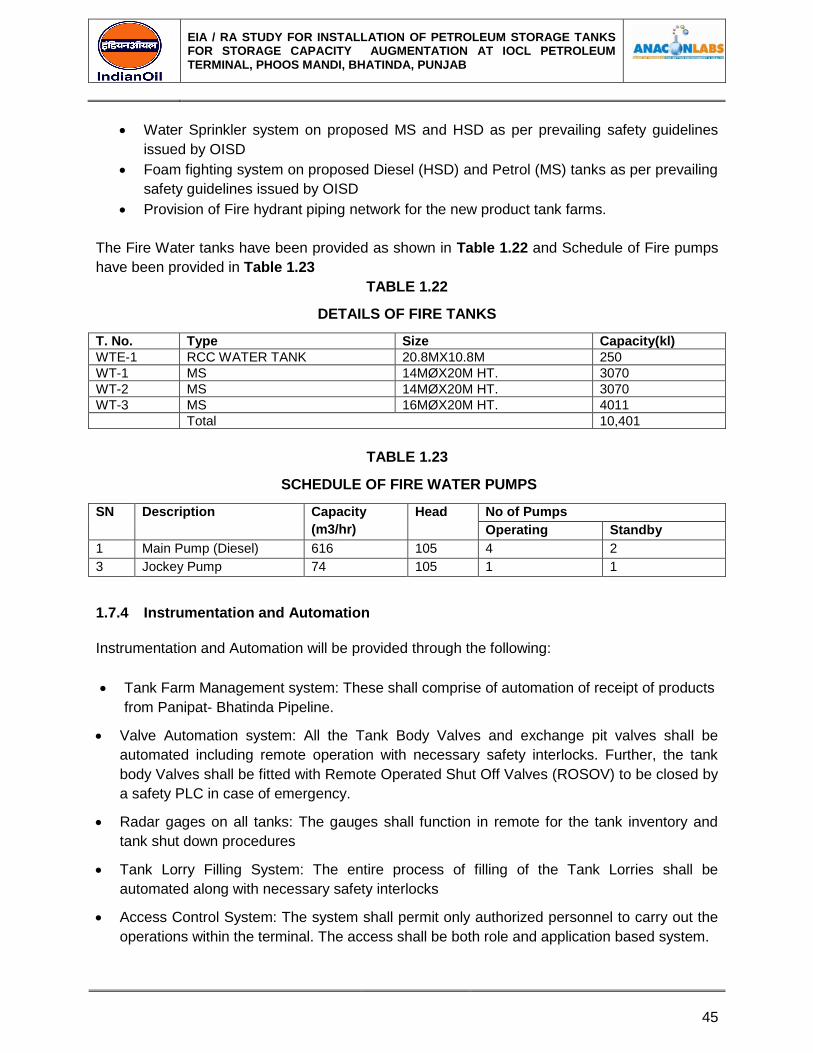
EIA / RA STUDY FOR INSTALLATION OF PETROLEUM STORAGE TANKS FOR STORAGE CAPACITY AUGMENTATION AT IOCL PETROLEUM TERMINAL, PHOOS MANDI, BHATINDA, PUNJAB
45
Water Sprinkler system on proposed MS and HSD as per prevailing safety guidelines
issued by OISD
Foam fighting system on proposed Diesel (HSD) and Petrol (MS) tanks as per prevailing
safety guidelines issued by OISD
Provision of Fire hydrant piping network for the new product tank farms.
The Fire Water tanks have been provided as shown in Table 1.22 and Schedule of Fire pumps
have been provided in Table 1.23
TABLE 1.22
DETAILS OF FIRE TANKS
T. No. Type Size Capacity(kl)
WTE-1 RCC WATER TANK 20.8MX10.8M 250
WT-1 MS 14MØX20M HT. 3070
WT-2 MS 14MØX20M HT. 3070
WT-3 MS 16MØX20M HT. 4011
Total 10,401
TABLE 1.23
SCHEDULE OF FIRE WATER PUMPS
SN Description Capacity
(m3/hr)
Head No of Pumps
Operating Standby
1 Main Pump (Diesel) 616 105 4 2
3 Jockey Pump 74 105 1 1
1.7.4 Instrumentation and Automation
Instrumentation and Automation will be provided through the following:
Tank Farm Management system: These shall comprise of automation of receipt of products
from Panipat- Bhatinda Pipeline.
Valve Automation system: All the Tank Body Valves and exchange pit valves shall be
automated including remote operation with necessary safety interlocks. Further, the tank
body Valves shall be fitted with Remote Operated Shut Off Valves (ROSOV) to be closed by
a safety PLC in case of emergency.
Radar gages on all tanks: The gauges shall function in remote for the tank inventory and
tank shut down procedures
Tank Lorry Filling System: The entire process of filling of the Tank Lorries shall be
automated along with necessary safety interlocks
Access Control System: The system shall permit only authorized personnel to carry out the
operations within the terminal. The access shall be both role and application based system.
EIA / RA STUDY FOR INSTALLATION OF PETROLEUM STORAGE TANKS FOR STORAGE CAPACITY AUGMENTATION AT IOCL PETROLEUM TERMINAL, PHOOS MANDI, BHATINDA, PUNJAB
46
Control Room with equipment: The control room shall monitor and log all event pertaining to
the operation of the terminal on real time basis.
Emergency Shut Down Procedures for various terminal operation activities.
1.8 SAFETY MEASURES
Following safety and mitigation measures are proposed.
A. All product tank dyke wall/enclosure designed with 110% of the largest tank capacity.
As per OISD standards, all tanks are provided with an enclosure wall to contain any leak
from the tanks or in case of failure/rupture of the tank shell.
The dyke provided is designed to contain the 110% of volume of the tank & a free board
of 200 mm to take care of containment of oil in case of any leakage of tanks.
The dyke enclosure designed as mentioned above facilitates to fight fire caused by a
pool of oil
B. All product tanks to be provided with 2 nos. exclusive SIL 2 certified Radar gauges and
1 no additional over spill protection device to avoid any overflow of tanks.
All the proposed and existing product storage tanks shall be provided with 2 nos.
separate radar gauge with SIL 2 certification, which is an internationally accepted
standard.
Provision of 2 separate radar gages and monitoring of the same from control room/PLC
system helps to avoid any overflow of product. The radar gauges are linked to the
control room and shall give audio visual alarms at the control room in case of the product
level reaches higher than the specified level.
In addition to the above, 1 no exclusive and independent Automatic Overspill Protection
device is hard wired to the Remote Operated Shut Off Valve and Safety PLC of the
automation system. When the product level in the storage tanks rise beyond a pre-
defined and safe filling capacity, the Automated Overspill Protection System (AOPS) is
triggered and it overrides all operations and logics built in the system to implement total
shut down of the operations and closure of all valves of all tanks.
The above safety features prevent any overflow of petroleum product from the storage
tanks.
C. All product tanks to be provided with pneumatic fire and fail safe Remote Operated Shut
Off Valves.
All body valves of tanks shall be provided with Fire Safe and Fail Safe Pneumatic
actuated Remote Operated Shut Off Valves (ROSOV).
EIA / RA STUDY FOR INSTALLATION OF PETROLEUM STORAGE TANKS FOR STORAGE CAPACITY AUGMENTATION AT IOCL PETROLEUM TERMINAL, PHOOS MANDI, BHATINDA, PUNJAB
47
The ROSOVs shall be interlinked with the SIL 2 certified radar gauges, AOPS and
Safety PLC. Upon the product level reaching the set trip point of a tank, the ROSOVs
shall automatically close overriding all operational logics.
D. All body valves of tanks to be provided with Remote Open and Close facility outside the
dyke enclosure to operate during emergencies.
All valves of tanks shall be provided with an open and close push button just outside the
tank enclosure.
The same shall be used to close a particular valve of a tank in case of exigencies,
thereby eliminating man entry in to hazardous zone (dyke area) during spillage etc.
This system shall save human lives during emergencies and hazards due to proximity to
petroleum vapour.
E. Fire water storage to fight fire for a period of 4 hours as per OISD guidelines has been
planned for 2 simultaneous contingencies with full coverage of fire hydrant facilities to
the entire plant area and positioning of fire fighting equipments as per OISD standards.
Permanent fire water storage and fire hydrant system to cover the entire terminal
operating area shall be provided.
The water storage and pumping facilities shall be designed to cater 2 simultaneous
emergencies inside the terminal as mentioned below.
Fire water storage: 10,401 m3
Fire pumps –6X 616 m3/hr
Jockey pumps – 2 X 74m3/ hr.
Fire hydrant line network – 4200 m approx.
Fire fighting equipments – as per OISD 117 & OISD 244
F. High Volume Long Range remote operated monitors to be provided for all Class A
storage tanks.
In case of a fire, fire fighting can be done from the proposed High Volume Long Range
Monitors (HVLR).
The HVLRs shall have motorized valves with provision to operate remote from control
room.
As per OISD 117, 5 nos. of fixed type HVLR and 1no Mobile type HVLR with 1000 US
GPM capacity are being proposed for the terminal to cover tank farm fires.
G. Hydro carbon detection system to be provided for all tanks, drain valve and manifold in
Class A service.
To detect any leak and potential fire hazard, Hydro-Carbon Detection (HCD) system is
proposed for all tanks with Class A service, tank enclosure drain valves and product
piping manifolds.
EIA / RA STUDY FOR INSTALLATION OF PETROLEUM STORAGE TANKS FOR STORAGE CAPACITY AUGMENTATION AT IOCL PETROLEUM TERMINAL, PHOOS MANDI, BHATINDA, PUNJAB
48
The proposed HCD system shall be linked to the control room and shall alert the Control
room officer with audio visual alarm when the concentration of the petroleum vapour
exceed beyond pre-defined limits.
The following equipment are being planned for the terminal as part of the HCD system.
Point type Infra Red (IR) sensor – at each drain valve in tank farm.
Open path IR sensor (range: 0 to 40 m and 0 to 120 m) – at valves and manifold
of Class A product.
Portable Gas detector – 1 no.
Test filter – 1no.
H. Fixed water spray and fixed foam pourer system has been provided for all Class A
Tanks and for Class B tanks above 18 m diameter.
The fixed foam pourer system shall apply foam solution to the surface of fire to create
smothering effect and extinguishing of fire.
I. Flow switches shall be provided for all water draw off lines.
In order to have effective monitoring of water draining from product tanks, a flow switch
shall be installed on all drain valves of all tanks to alert the Control room.
J. Proposed Class A tank shall be constructed as internal floating roof tank.
In order to prevent exposure of petroleum vapour to open environment, the proposed
tank on Class A service shall be constructed as an internal floating roof tank with an
Aluminum floating deck and a fixed roof. This shall act as an additional safety feature
and shall minimize fires due to lightning etc.
K. Manual call points shall be provided at strategic places within the terminal.
Manual call points are proposed at strategic places inside the terminal to raise alarming
case of any exigency.
L. L. Receipt and delivery operation shall be done based on in built logic developed in
SCADA with site specific interlocks.
Tank operations like receipt and delivery shall be based on pre-defined logic and
controlled by PLC and SCADA systems.
This shall prevent wrong operations and risks like overflow of tanks.
M. Tank truck loading shall have interlocks to monitor grounding of the truck, position of the
loading arm and over flow protection system.
EIA / RA STUDY FOR INSTALLATION OF PETROLEUM STORAGE TANKS FOR STORAGE CAPACITY AUGMENTATION AT IOCL PETROLEUM TERMINAL, PHOOS MANDI, BHATINDA, PUNJAB
49
Tank truck operation shall be designed with the following interlocks to avoid fire hazards.
Grounding interlock – To stop loading in the absence of proper grounding and to prevent
fire due to static electricity.
Position sensor/ level switch on loading arm – The batch controller commences tank
truck loading based on the feedback from loading arm’s position sensor is inserted in to
the tank truck compartment. Similarly, the batch controller shall stop loading based on a
feedback from a level switch of loading arm to prevent any overflow of tank truck.\
N. Separate Safety PLC planned for interlinking of all safety features and for ensuring total
shut down of the plant.
O. CCTV system shall be provided as per security guidelines applicable and shall be linked
with Safety PLC.
1.8.1 Personal Protective Equipment
The following of personal protective equipment will be available during an emergency.
(i) Fire proximity suit - 1 no
(ii) Fire entry suit - Nil
(iii) Water gel blanket - 2 no.
(iv) Safety helmet - 70 nos.
(v) Rubber hand gloves for use in electrical jobs -2 pair.
(vi) BA Set - 1 no.
The quantities available are sufficient to meet the needs of emergency handling personnel.
1.8.2 Rehearsal and Testing
'Fire Drills' are arranged periodically to test out the laid down system and facilities. The
emergency handlers also "act out" their individual roles in accordance with the emergency
procedures laid down to demonstrate that the entire emergency response system can perform
efficiently and accurately. Mock drills for emergency is to be conducted twice in an year.
1.9 SALIENT FEATURES OF ON-SITE EMERGENCY
Effect distances for various range of distances against a heat flux of 4.5 KW/M2.People will
have to be evacuated in the event of fire.
1.10 OFF-SITE EMERGENCY PLAN
An integral part of the Disaster Management Plan is the Off-Site Emergency Plan. The plan is
mainly dependent upon a very close co-ordination and assistance from the Local Administration
like Police, Fire Brigade, Medical Services (hospitals) etc.
1.10.1 Off-Site Action
The Chief Controller will inform about the incident like Fire, Explosions to –
(i) Police and District Collector.
EIA / RA STUDY FOR INSTALLATION OF PETROLEUM STORAGE TANKS FOR STORAGE CAPACITY AUGMENTATION AT IOCL PETROLEUM TERMINAL, PHOOS MANDI, BHATINDA, PUNJAB
50
(ii) Fire Brigade.
(iii) Medical Services.
(iv) Technical/Statutory Bodies.
(v) Rehabilitation Agencies.
(vi) Electricity Board.
1.10.2 Responsibilities of the Services
1] Police
1. To control traffic & mob by cordoning off the area.
2. Arrange for evacuation of people on advice from the Site Controller/District Collector.
3. Broadcast/communicate through public address systems to the community on advise
from the District/Sub Collector.
4. Inform relatives about details of injured and casualties.
2] Fire Brigade
1. Fighting fire & preventing its spread.
2. Rescue & salvage operation.
3] Medical/Ambulance
1. First Aid to the injured persons.
2. Shifting critically injured patients to the hospitals.
3. Providing medical treatment.
4] Technical/Statutory Bodies
(Constitutes Factory Inspectorate, Pollution Control Board, Technical Experts from
Industries)
1. Provide all technical information to the emergency services, as required.
2. Investigate the cause of the disaster.
5] Rehabilitation
1. Arrange for evacuation of persons to nominated rescue centre and arrange for their
food, medical and hygienic requirements.
2. Coordinating with the Insurance Companies for prompt disbursement of compensation to
the affected persons.
3. Maintain communication channels of the affected industry like telephone, telex etc. in
perfect working condition.
6] Electricity Board
To put off the power supply to the Terminal, if specifically asked for by IOCL.
7] Important Telephone Numbers Who May be
Contacted during Emergency:
1. Police station 100

EIA / RA STUDY FOR INSTALLATION OF PETROLEUM STORAGE TANKS FOR STORAGE CAPACITY AUGMENTATION AT IOCL PETROLEUM TERMINAL, PHOOS MANDI, BHATINDA, PUNJAB
51
2. Hospital 108
3. Fire Brigade 101
4. DC
5. Terminal manager