10 drill press - mecanair
TRANSCRIPT

10" DRILL PRESS
Instruction ManualToll-Free Helpline1-800-689-9928
Item No.: 055-5509-2

2
Table of contents
I. Specifications
SECTION PAGEI.II.III. IV. V. VI. VII. VIII.IX.X.
231012132327282930
Specifications........................................................................General safety guidelines......................................................Electrical information.............................................................Know your drill press.............................................................Assembly and adjustments...................................................Operating instructions........................................................... Maintenance..........................................................................Troubleshooting.....................................................................Warranty................................................................................Parts list.................................................................................
Model: Motor:Spindle travel:Column diameter:Max. drilling capacity:Pulley speeds:Table size:Base size:
055-5509-2120 V 60 Hz 4.1 A50 mm50 mm5/8" diameter620, 1150, 1630, 2180, 3070 RPM (no load)7 1/4 x 7 1/4"13 3/8 x 8 1/4"

3
II. General safety guidelines
WARNING! READ ALL INSTRUCTIONS Failure to follow the safety rules listed below and otherbasic safety precautions may result in serious personal injury.
Work AreaKEEP CHILDREN AWAYDo not let visitors contact tool or extension cord. All visitors should be kept safe distance from workarea.
KEEP WORK AREAS CLEANCluttered areas and benches invite accidents.
MAKE WORKSHOP CHILD-PROOFWith padlocks, master switches, or by removing starter keys.
AVOID DANGEROUS ENVIRONMENTSDon’t use power tools in damp or wet locations. Keep work area well lit. Do not expose power toolsto rain. Do not use the tool in the presence of flammable liquids or gases.
Personal SafetyKNOW YOUR POWER TOOLRead and understand the owner’s manual and labels affixed to the tool. Learn its application andlimitations as well as the specific potential hazards particular to this tool.
DON’T OVERREACHKeep proper footing and balance at all times.
STAY ALERTWatch what you are doing. Use common sense. Do not operate tool when you are tired. Do notoperate while under medication or while using alcohol or other drugs.
WEAR PROPER APPARELDo not wear lose clothing, gloves, neckties, rings, bracelets, or other jewelry which may get caughtin moving parts. Nonslip footwear is recommended. Wear protective hair covering to contain longhair.
ALWAYS USE SAFETY GLASSESAlso use face or dust mask if cutting operation is dusty, and ear plugs during extended periods ofoperation. Everyday eyeglasses have only impact resistant lenses, they are NOT safety glasses.
GUARD AGAINST ELECTRIC SHOCKPrevent body contact with grounded surfaces. For example: pipes, radiators, ranges, refrigeratorenclosures.
DISCONNECT TOOLS FROM POWER SOURCEWhen not in use, before servicing, when changing blades, bits, cutters, etc.
KEEP GUARDS IN PLACEIn working order, and in proper adjustment and alignment.
REMOVE ADJUSTING KEYS AND WRENCHESWhen not in use, before servicing, when changing blades, bits, cutters, etc.
REDUCE THE RISK OF UNINTENTIONAL STARTING

WARNING! All repairs, electrical or mechanical, should be attempted only by trained repairmen.Contact the nearest Mastercraft® Service Centre, Authorized Service Station or other competentrepair service.
Make sure the switch is in the “OFF” position before plugging in tool.
GROUND ALL TOOLSThis tool is equipped with an approved 3-conductor cord and a 3-prong grounding type plug to fitthe proper grounding type receptacle. The green conductor in the cord is the grounding wire.Never connect the green wire to a live terminal.
NEVER STAND ON TOOL OR ITS STANDSerious injury could occur if the tool is tipped or if the cutting tool is accidentally contacted. Do notstore materials on or near the tool such that it is necessary to stand on the tool or its stand to reachthem.
CHECK DAMAGED PARTSBefore further use of the tool, a guard or other part that is damaged should be carefully checkedto ensure that it will operate properly and perform its intended function. Check for alignment ofmoving parts, mounting, and any other conditions that may affect its operation. A guard or otherpart that is damaged should be properly replaced.
ADDITIONAL SAFETY GUIDELINES FOR DRILL PRESSTool UseDON’T FORCE TOOLIt will do the job better and safer at the rate for which it was designed.
USE THE RIGHT TOOLDon’t force a small tool or attachment to do the job of a heavy duty tool. Don’t use tool for purposenot intended—for example, don’t use a circular saw for cutting tree limbs or logs.
SECURE WORKUse clamps or vise to hold work. It is safer than using your hand and it frees both hands to operatethe tool.
NEVER LEAVE TOOL RUNNING UNATTENDEDTurn power off. Don’t leave tool until it comes to a complete stop.
Tool CareDO NOT ALTER OR MISUSE TOOLThese tools are precision built. Any alteration or modification not specified is misuse andmay result in dangerous conditions.
II. General safety guidelines (continued)
4
WARNING! Use only Mastercraft® replacement parts; any others may create a hazard.
WARNING! The use of any other accessories not specified in the current Mastercraft® catalogmay create a hazard.

WARNING! For your own safety, do not operate your drill press until it is completely assembledand installed according to the instructions … and until you have read and understood the following:1. General safety guidelines2. Specifications3. Know your drill press4. Assembly and adjustments5. Operation7. Maintaining your drill press8. Troubleshooting9. STABILITY OF THE DRILL PRESSIf there is any tendency of the drill press to tilt or move during use, bolt it to the bench top or to apiece of 3/4" exterior plywood large enough to stabilize the drill press. Bolt the plywood to theunderside of the base so it extends beyond the sides of the base. DO NOT USE PRESSED WOODPANELS. They can break unexpectedly. If the workpiece is too large to easily support with onehand, provide an auxiliary support.10. LOCATIONUse the drill press in a well lit area and on a level surface, clean and smooth enough to reduce therisk of trips and falls. Use it where neither the operator nor the casual observer is forced to standin line with a potential kickback.11. PROTECTION: Eyes, hands, ears and body. TO AVOID BEING PULLED INTO THE SPINNING TOOL—DO NOT WEAR: Loose fitting gloves Necktie Loose clothing JewelryDO: TIE BACK LONG HAIR ROLL LONG SLEEVES ABOVE ELBOWS
AVOID GASEOUS AREASDo not operate electric tools in a gaseous or explosive atmosphere. Motors in these tools normallyspark, and this may result in a dangerous condition.
MAINTAIN TOOLS WITH CAREKeep tools sharp and clean for best and safest performance. Follow instructions for lubricating andchanging accessories. Inspect tool cords periodically and if damaged, have repaired by authorizedservice facility. Inspect extension cords periodically and replace if damaged. Keep handles dry,clean and free from oil and grease.
5
II. General safety guidelines (continued)
KEEP THIS USER’S MANUAL IN A SAFE PLACE FOR FUTURE REFERENCE
WARNING! Before connecting the tool to a power source (receptacle, outlet, etc.), be surevoltage supplied is the same as that specified on the nameplate of the tool. A power source witha voltage greater than that specified for the tool can result in serious injury to the user, as wellas damage to the tool. If in doubt, DO NOT PLUG IN THE TOOL. Using a power source witha voltage less than the nameplate rating is harmful to the motor.

6
II. General safety guidelines (continued)
a. If any part of your drill press is missing, malfunctioning, has been damaged or broken, suchas the motor switch, or other operating control, a safety device or the power cord, cease operatingimmediately until the particular part is properly repaired or replaced.b. Never place your fingers in a position where they could contact the drill bit or other cutting toolif the workpiece should unexpectedly shift or your hand should slip.c. To avoid injury from parts thrown by the spring, follow the instructions exactly as given andshown in “SPINDLE RETURN SPRING” section.d. To prevent the workpiece from being torn from your hands, spinning on the table, shattering thetool, or being thrown, always support your work so it won’t shift or bind on the tool.• Always position “backup material” (used beneath the workpiece) to contact the left side of thecolumn.• Whenever possible, position the workpiece to contact the left side of the column — if it is short orthe table is tilted, clamp solidly to the table. Use table slots or clamping ledge around the outsideedge of the table.• When using a drill press vise, always fasten to the table.• Never do any work “free hand” (hand holding a workpiece rather than supporting it on the table),except when polishing.• Securely lock head and table support to column, and table to table support before operating drillpress.• Never move the head or table support while the tool is running.• Before starting the operation, jog the motor switch to make sure the drill bit or other cutting tooldoes not wobble or cause vibration.• If a workpiece overhangs the table such that it will fall or tip if not held, clamp it to the table orprovide auxiliary support.• Use fixtures for unusual operations to adequately hold, guide and position the workpiece.• Use the SPINDLE SPEED recommended for the specific operation and workpiece material —check the panel inside the pulley cover for drilling information; for accessories, refer to theinstructions provided with the accessories.e. Never climb on the drill press table; it could break or pull the entire drill press down on you.f. Turn the motor switch “OFF” and unplug from power source when not in operation.g. To avoid injury from thrown work or tool contact, DO NOT perform layout, assembly, or setupwork on the table while the cutting tool is rotating.12. USE ONLY ACCESSORIES DESIGNED FOR THIS DRILL PRESS TO AVOID SERIOUSINJURY FROM THROWN, BROKEN PARTS OR WORK PIECES.a. WHEN CUTTING LARGE DIAMETER HOLES: Clamp the workpiece firmly to the table. Otherwisethe cutter may grab and spin at high speed. Use only one-piece, cup-type, hole cutters. DO NOTuse fly cutters or multi-part hole cutters as they come apart or become unbalanced in use.
KEEP THIS USER’S MANUAL IN A SAFE PLACE FOR FUTURE REFERENCE
7
II. General safety guidelines (continued)
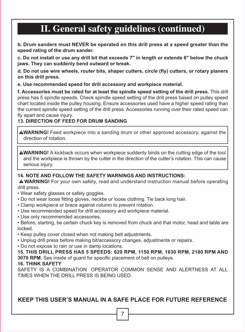
b. Drum sanders must NEVER be operated on this drill press at a speed greater than thespeed rating of the drum sander.c. Do not install or use any drill bit that exceeds 7" in length or extends 6" below the chuckjaws. They can suddenly bend outward or break.d. Do not use wire wheels, router bits, shaper cutters, circle (fly) cutters, or rotary planerson this drill press.e. Use recommended speed for drill accessory and workpiece material.f. Accessories must be rated for at least the spindle speed setting of the drill press. This drillpress has 5 spindle speeds. Check spindle speed setting of the drill press based on pulley speedchart located inside the pulley housing. Ensure accessories used have a higher speed rating thanthe current spindle speed setting of the drill press. Accessories running over their rated speed canfly apart and cause injury.13. DIRECTION OF FEED FOR DRUM SANDING
14. NOTE AND FOLLOW THE SAFETY WARNINGS AND INSTRUCTIONS: WARNING! For your own safety, read and understand instruction manual before operatingdrill press.• Wear safety glasses or safety goggles.• Do not wear loose fitting gloves, necktie or loose clothing. Tie back long hair.• Clamp workpiece or brace against column to prevent rotation.• Use recommended speed for drill accessory and workpiece material.• Use only recommended accessories.• Before, starting, be certain chuck key is removed from chuck and that motor, head and table arelocked.• Keep pulley cover closed when not making belt adjustments.• Unplug drill press before making bit/accessory changes, adjustments or repairs.• Do not expose to rain or use in damp locations.15. THIS DRILL PRESS HAS 5 SPEEDS: 620 RPM, 1150 RPM, 1630 RPM, 2180 RPM AND3070 RPM. See inside of guard for specific placement of belt on pulleys.16. THINK SAFETYSAFETY IS A COMBINATION OPERATOR COMMON SENSE AND ALERTNESS AT ALLTIMES WHEN THE DRILL PRESS IS BEING USED.
KEEP THIS USER’S MANUAL IN A SAFE PLACE FOR FUTURE REFERENCE
WARNING! Feed workpiece into a sanding drum or other approved accessory, against thedirection of rotation.
WARNING! A kickback occurs when workpiece suddenly binds on the cutting edge of the tooland the workpiece is thrown by the cutter in the direction of the cutter’s rotation. This can causeserious injury.

8
II. General safety guidelines (continued)
KEEP THIS USER’S MANUAL IN A SAFE PLACE FOR FUTURE REFERENCE
WARNING! Do not allow familiarity (gained from frequent use of your drill press) to becomecommonplace. Always remember that a careless fraction of a second is sufficient to inflictsevere injury.
WARNING! WEAR EYE PROTECTION! The operation of any power tool can result in foreignobjects being thrown into the eyes, which can result in severe eye damage. Always wear safetygoggles before commencing power tool operation.
WARNING! Some dust created by power sanding, sawing, grinding, drilling, and otherconstruction activities contains chemicals known to cause cancer, birth defects or otherreproductive harm. Some examples of these chemicals are:• Lead from lead-based paints• Crystalline silica from bricks and cement and other masonry products• Arsenic and chromium from chemically treated lumberYour risk from these exposures varies, depending on how often you do this type of work. To reduceyour exposure to these chemicals: work in a well ventilated area and work with approved safetyequipment, such as dust masks that are specially designed to filter out microscopic particles.
LASER SAFETYWARNING! To reduce the risk of injury:1. Do not stare directly at the laser beam. Eye damage may occur if you deliberately stare into thebeam.2. The laser light beam used in this system is Class II with maximum output 1 mW and 650 nmwavelength. AVOID DIRECT EYE EXPOSURE.3. The laser must be used and maintained in accordance with the manufacturer’s instructions:• Never aim the beam at any person or an object other than the workpiece.• Do not project the laser beam into the eyes of others.• Always ensure the laser beam is aimed at a workpiece without reflective surfaces as the laserbeam could be projected into your eyes or the eyes of others. CAUTION! Use of controls or adjustments or performance of procedures other than thosespecified herein may result in hazardous radiation exposure.
RAYONNEMENT LASER. NE REGARDEZ PASDIRECTEMENT DANS LE FAISCEAU.LASER RADIATION. DO NOT STARE INTO BEAM.
Longueur d’onde / Wavelength: 650 nmPuissance maximale / Max. Output: 1 mWProduit laser de classe IIClass II Laser ProductConforme au règlement 21 CFR sections 1040.10eComplies with 21 CFR 1040.10e
! ATTENTION/CAUTION

9
II. General safety guidelines (continued)
WARNING! EXPOSURE TO EXCESSIVE NOISE LEVELS CAN RESULT IN PERMANENTHEARING LOSS. ALWAYS WEAR EAR PROTECTION (SAFETY EAR MUFFS OR EARPLUGS) TO REDUCE NOISE LEVELS WHEN OPERATING THE DRILL PRESS.
ALWAYS WEAR EYE PROTECTION THAT CONFORMS WITH CSA
REQUIREMENTS.
FLYING DEBRIS can cause permanent eye damage.
Prescription eyeglasses are not a replacement for proper eye protection.

1 - Current carrying prongs2 - Grounding outlet box3 - Grounding blade is longest of the 3 blades
MOTOR SPECIFICATIONSIn the event of a malfunction or breakdown, grounding provides a path of least resistancefor electric current to reduce the risk of electric shock. This tool is equipped with an electric cordhaving an equipment-grounding conductor and a grounding plug. The plug must be plugged into amatching outlet that is properly installed and grounded in accordance with all local codesand ordinances.This Drill Press is designed to use a 1795 RPM motor. It is wired for operation on 110-120 V,60 Hz. alternating current. Before connecting the motor cord to power source, make certain theswitch is in the “OFF” position and be sure the electric current is of the same characteristics asstamped on the drill press nameplate.
CONNECTION TO A POWER SOURCEThis machine must be grounded while in use to protect the operator from electric shock.Plug power cord into a 110-120 V properly grounded type outlet protected by a 15 A dual elementtime delay fuse or circuit breaker.Not all outlets are properly grounded. If you are not sure that your outlet, as pictured in Fig. A, isproperly grounded; have it checked by a qualified electrician.
10
III. Electrical information
Fig. A 1
3
2
DANGER: To avoid electric shock, do not touch the metal prongs on the plug when insertingor removing the plug into or from the outlet. DANGER: Failure to properly ground this power tool can cause electrocution or serious shock,particularly when used near metal plumbing or other metal objects. If shocked, your reaction couldcause your hands to hit the tool. WARNING: If power cord is worn, cut or damaged in any way, have it replaced immediately toavoid shock or fire hazard.Your unit is for use on 120 V; it has a plug that lookslike the one in Figure A.This power tool is equipped with a 3-conductor cordand grounding type plug, approved by UnderwritersLaboratories and the Canadian Standards Association.The ground conductor has a green jacket and isattached to the tool housing at one end and to theground prong in the attachment plug at the other end.
If the outlet you are planning to use for this power toolis of the two-prong type, DO NOT REMOVE OR ALTERTHE GROUNDING PRONG IN ANY MANNER. Have a qualified electrician replace the TWO-holeoutlet with a properly grounded THREE-hole outlet.
Improper connection of the equipment-grounding conductor can result in a risk of electric shock.The conductor with insulation having an outer surface that is green with or without yellow stripesis the equipment conductor. If repair or replacement of the electric cord or plug is necessary, do notconnect the equipment grounding conductor to a live terminal.
Check with a qualified electrician or service personnel if the grounding instructions are not completelyunderstood, or if in doubt as to whether the tool is properly grounded.

11
III. Electrical information (continued)
Always use proper extension cord. The use of any extension cord will cause some loss of power.To keep this to a minimum and to prevent overheating and motor burn-out, use the table below todetermine the minimum wire size (A.W.G.) extension cord. Use only 3-wire extension cords whichhave 3-prong grounding type plugs and 3-pole receptacles which accept the tool’s plug. Make sureyour extension cord is in good condition.
Extension Cord Length0–25' (0–7.6 m)26–50' (7.7–15.3 m)51–100' (15.4–30.5 m)
Wire Size A.W.G. . . . . . . . . . . . . . . . . . . . . . . . . . . . . . . . . . . . . . . . . . . . . . . . . . . . . . . . . . . . . .18
. . . . . . . . . . . . . . . . . . . . . . . . . . . . . . . . . . . . . . . . . . . . . . . . . . . . . . . . . . .16. . . . . . . . . . . . . . . . . . . . . . . . . . . . . . . . . . . . . . . . . . . . . . . . . . . . . . . . .16

12
IV. Know your drill press
1 Pulley housing cover2 Laser switch3 Locking screws4 Power cord5 Rack collar6 Support lock handle7 Bevel scale8 On/off switch9 Feed return spring and cover10 Laser lights11 Chuck12 Chuck key13 Pulley housing screw14 Belt/pulley speed chart15 Motor pulley
16 Belt17 Spindle pulley18 Depth scale19 Pointer20 Quill21 Table22 Column support23 Feed handle24 Motor25 Tension lock knob26 Depth tension knob27 Column28 Rack29 Crank handle30 Base
151617
1413
11
89
10
1
2345
19
18
20
22
2129
30
23
24
2625
2728
12
6
7

ABCDEFGH
Head assemblyBaseTable/support assemblyCrank handleChuckFeed handlesRackColumn/support assembly
I J KLMNOP
Rack collarFlat washers M8Spring washers M8Bolts M8x25Batteries3 mm/4 mm Allen wrenchChuck keyInstruction manual
A
F
J K L M N O P
G H I
B C D E
UNPACKING
MASTERCRAFT® Drill Press is shipped complete in one box.1. Unpacking and Checking Contents. Separate all parts from packing materials and check eachone with the “Table of Loose Parts” to make sure all items are accounted for before discarding anypacking material.
2. Remove the protective oil that is applied to table, base and column. Use any ordinary householdtype grease and spot remover.
3. Apply a coat of paste wax to the table, column and machined surfaces of base to prevent rust.Wipe all parts thoroughly with a clean dry cloth.
10" DRILL PRESS
Item No.:055-5502-6
Instruction Manual
Toll-Free Helpline
1-800-689-9928
V. Assembly and adjustments
WARNING: To reduce the risk of injury, never connect plug to power source outlet untilall assembly steps are complete and until you have read and understood the entire owner’smanual.
13
WARNING: If any parts are missing, do not attempt to assemble the drill press, plug in powercord or turn the switch on until the missing parts are obtained and are installed correctly.
WARNING: To avoid fire or toxic reaction, never use gasoline, naptha or similar highly volatilesolvents.

ASSEMBLY AND ADJUSTMENTS
14
TOOLS NEEDED FOR ASSEMBLY• Adjustable wrench• Screwdriver• Hammer and block of wood
BASE TO COLUMN (Fig. 1)1. Set the base (1) on the floor.2. Place the column tube (2) on the base (1), alignthe column support holes with the base holes.3. Install a bolt M8 x 25 (3), a flat wahser M8 (4) anda spring washer M8 (5) in each column support holeand tighten with the wrench.
TABLE TO COLUMN (Fig. 2–4)1. Insert the rack (1) into the geared groove of thetable support (2). Make sure the worm shaft (3) on theinside of the table support is engaged with the teethof the rack. The table support should sit at the centreof the rack.2. Slide the table support and rack assembly (1, 2, 3)down together onto the column. Insert the bottomedge of the rack into the lip (4) of the column support.HOLD IN THIS POSITION until step 3 is completed.3. Place the collar (5) bevel side down over the rack.Tighten the set screw (6) with the 3 mm Allen wrenchto hold the rack in position. Note: Make sure there is enough clearance to allowthe table to rotate around the column. The collar mustsit loosely over rack and not angled on the column.To avoid column or collar damage, only tighten the setscrew enough to keep collar in place (Fig. 3).4. Insert the table support crank handle (7) into theworm gear shaft on the side of the table support (8).Make sure the set screw (9) is aligned on the flat ofthe shaft and as close to the table support as possible.Tighten the set screw (Fig. 4).5. Position the table in the same direction as the base,and tighten the column lock handle (10).
V. Assembly and adjustments (continued)
Fig. 4
WARNING: To reduce the risk of injury, neverconnect plug to power source outlet until all assemblysteps are completed.
1089
7
Fig. 1
15
34
2
Fig. 36 5
Fig. 2 1
3
2
4

15
DRILL PRESS HEAD TO COLUMN (Fig. 5)1. Lift the drill press head assembly (1) carefully andplace the mounting hole of the drill press head ontothe top of the column (2). Make sure the head isseated properly on the column.2. Align the direction of the drill press head to thedirection of the base and the table.3. Tighten the two set screws (3) using an allen wrench.
FEED HANDLES (Fig. 6)1. Thread the three feed handle rods (1) into the holeson the feed hub (2).2. Hand tighten. Note: One or two of the feed handles may beremoved if an unusually-shaped workpiece interfereswith handle rotation.
LASER BATTERIES (Fig. 7)1. Turn off the laser.2. Push the tab (1) located on the laser switch cover(2) down and towards you, then remove it.3. Insert 2 “AAA” batteries in the laser batterycompartment (4).4. Replace the laser switch cover. CAUTION: Remove the laser light batteries whenthe tool is to be stored without use for a few days ormore. If left in position, the batteries might leak anddamage the laser light assembly. Damage due toleaking batteries is not covered under the warranty.
MOUNT THE DRILL PRESS (Fig. 8)Your drill press must be securely fastened through themounting holes (1) to a stand or work bench withheavyduty fasteners. This will prevent the drill pressfrom tipping over, sliding, or walking during operation. IMPORTANT: If the stand or workbench has atendency to move during operation, fasten it securelyto the floor.
V. Assembly and adjustments (continued)
Fig. 5
Fig. 6
Fig. 7
Fig. 8
1
2
2
2
1
3
1
1
3
1
2

16
INSTALL THE CHUCK (Fig. 9)1. Inspect and clean the taper hole in the chuck (1)and the spindle (2). Remove all grease, coatings, andparticles from the chuck and spindle surfaces with aclean cloth.2. Open the chuck jaws (3) by turning the chuck barrelclockwise by hand. Make sure the jaws are completelyrecessed inside the chuck.3. Seat the chuck on the spindle by placing a block ofwood (4) under the chuck (1) and tapping the woodwith a hammer (5) or tap the chuck with a rubbermallet. CAUTION: To avoid damaging the chuck, makesure the jaws are completely recessed into the chuck.Do not use a metal hammer directly to drive the chuckinto the spindle.
REMOVE THE CHUCK (Fig. 10)1. Turn the feed handles (1) to lower the chuck (2) tothe lowest position.2. Place a ball joint separator (not shown) above thechuck (3) and tap it lightly with a hammer (4) to causethe chuck to drop from the spindle. Note: To avoid possible damage, be prepared tocatch the chuck as it falls.
V. Assembly and adjustments (continued)
Fig. 91
2
3
5
1
3
4 2
4
Fig. 10

17
V. Assembly and adjustments (continued)
WARNING: To reduce the risk of injury:• Turn switch “OFF” and remove plug from the power source before making adjustments.• Follow instructions carefully and wear eye protection to avoid thrown parts due to spring release.• Never operate drill press with pulley cover open.
OPERATING ADJUSTMENTS
INSTALL THE BELT (Fig. 11)1. Open the pulley and belt cover (1).2. Loosen the belt tension lock knobs (2) on both sidesof the drill press.3. Slide the motor (3) as close to the drill press headas possible.4. Place a belt (4) on the motor pulley (5) and thespindle pulley (6) in the proper position for the desiredspeed.5. Pull the motor away from the drill press head untilthe belt is properly tensioned. Tighten the belt tensionlock knobs (2). Note: The belt (4) should be tight enough to preventslippage. Correct tension is set if the belt flexes about1/2" (13 mm) when thumb pressure is applied at themidpoint of the belt between the pulleys.
ALIGN THE BELT PULLEYS (Fig. 12)1. Check the alignment of the pulleys with a straightedge (1) (such as a ruler, level, or framing square) bylaying the straight edge across the top of the pulleys(2).2. If the pulleys are NOT aligned, release belt tensionby loosening the belt tension lock knobs (3) on bothsides of the head.3. Loosen the motor mount nuts (4) with an adjustablewrench, and lower or raise the motor until the pulleysare aligned.4. Tighten the motor mount nuts (4) with an adjustablewrench to maintain the position.5. Lock the motor for the proper belt tension and tightenthe tension lock knobs (3).
Fig. 11
Fig. 12
2 3
6
2
1
3
4
4
5
1
1/2”
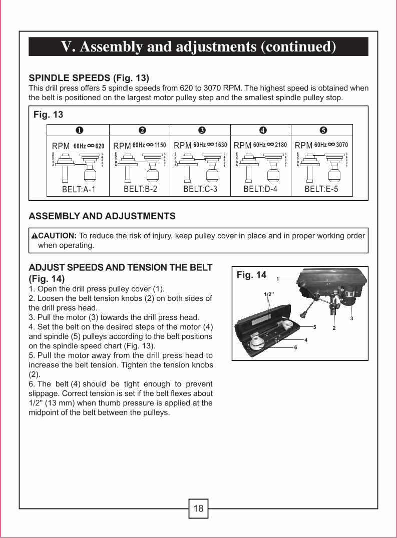
SPINDLE SPEEDS (Fig. 13)This drill press offers 5 spindle speeds from 620 to 3070 RPM. The highest speed is obtained whenthe belt is positioned on the largest motor pulley step and the smallest spindle pulley stop.
ADJUST SPEEDS AND TENSION THE BELT(Fig. 14)1. Open the drill press pulley cover (1).2. Loosen the belt tension knobs (2) on both sides ofthe drill press head.3. Pull the motor (3) towards the drill press head.4. Set the belt on the desired steps of the motor (4)and spindle (5) pulleys according to the belt positionson the spindle speed chart (Fig. 13).5. Pull the motor away from the drill press head toincrease the belt tension. Tighten the tension knobs(2).6. The belt (4) should be tight enough to preventslippage. Correct tension is set if the belt flexes about1/2" (13 mm) when thumb pressure is applied at themidpoint of the belt between the pulleys.
ASSEMBLY AND ADJUSTMENTS
CAUTION: To reduce the risk of injury, keep pulley cover in place and in proper working orderwhen operating.
Fig. 14
2
3
64
5
1
1/2”
18
V. Assembly and adjustments (continued)
Fig. 13

TABLE ADJUSTMENTS TO RAISE ORLOWER (Fig. 15)1. Raise or lower the table by loosening the columnlock handle (1) and turning the crank handle (2) untilthe table is at the desired height.2. Tighten the table lock handle (1) before drilling.3. Rotate the table around the column by looseningthe column lock handle (1) and turning the tablearound the column to the desired position.4. Tighten the lock handle before drilling.
TO TILT THE TABLE (Fig. 16)The table can be tilted from 0 to 45° to the left and right.1. Loosen the bevel lock bolt (1) with a wrench.2. Tilt the table (2) to the desired angle, using thebevel scale (3) as a basic guide.3. Re-tighten the bevel lock bolt (1).4. To return the table to its original position, loosen thebevel lock bolt. Realign the bevel scale (3) to the 0°setting.5. Tighten the bevel lock bolt (1) with the wrench.
TO SQUARE THE TABLE TO THE HEAD(Fig. 17)1. Insert a 3" (7.6 cm) drill bit (1) into the chuck (2) andtighten.2. Raise and lock the table (3) about 1" (2.5 cm) fromthe end of the drill bit.3. Place a combination square (4) on the table asshown. The drill bit should be parallel to the straightedge of the square.4. If an adjustment is needed, loosen the bevel lock (5)with a wrench.5. Square the table to the bit by tilting the table.6. Tighten the bevel lock bolt (5) when square.
Fig. 15
Fig. 17
1
2
19
V. Assembly and adjustments (continued)
Fig. 162
1
3
2 1
345

DRILLING DEPTH (Fig. 18)1. To stop the drill at a specific depth for consistentand repetitive drilling, loosen the depth scale lock (1)located on the depth scale hub (2).2. Turn the hub until the pointer (3) is aligned to thedesired depth on the scale.3. Tighten the depth scale lock (1). The chuck will stopafter traveling downward to the distance selected.
SPINDLE RETURN SPRING (Fig. 19)The spindle is equipped with an auto-return mechanism.The main components are a spring and a notchedhousing. The spring was properly adjusted at the factoryand should not be readjusted unless absolutelynecessary. If it needs to be adjusted, proceed asfollows:1. Unplug the drill press.2. Place a screwdriver into the loop (1) to hold thespring in place.3. Loosen the two housing nuts (2) approximately 1/4"(6 mm). Do not remove the nuts from the threadedshaft.4. While firmly holding the spring housing (3), carefullypull it out until it clears the raised notch (4). Turn it untilthe next notch (5) is engaged with the raised notch (toincrease the tension, turn it counterclockwise; todecrease the tension, turn it clockwise). Tighten thetwo housing nuts. IMPORTANT: Do not overtighten the two nuts. Ifthe nuts are tightened too much, the movement of thespindle and feed handles will be sluggish.
ANGULAR PLAY OF THE SPINDLE (Fig. 20)Move the spindle to the lowest downward position andhold in place. With your other hand, try to makeit revolve around its axis with a side motion. If there istoo much play proceed as follows:1. Loosen the lock nut (1).2. Turn the screw clockwise to eliminate the playbut without obstructing the upward and downwardmotion of the spindle (a little bit of play is normal).3. Tighten the lock nut (1).
Fig. 18
20
V. Assembly and adjustments (continued)
3
2
1
4
5
Fig. 20
1
1
2
3
Fig. 19

WARNING: DO NOT STARE DIRECTLY AT THE LASER BEAM! Deliberately staring intothe beam couuld be hazardous. Please observe all safety rules as follows:• The laser must be used and maintained in accordance with the manufacturer's instructions.• Never aim the beam at any person or an object other than the workpiece.• Do not project the laser beam into the eyes of others.• Always ensure the laser beam is aimed at a workpiece without reflective surfaces as the laser beam could be projected into your eyes or the eyes of others.
INSTALL DRILL BITS (Fig. 21)1. Place the chuck key (1) into the side keyhole of thechuck (2), meshing the gear teeth (3).2. Turn the chuck key counterclockwise to open thechuck jaws (4).3. Insert a drill bit into the chuck far enough to obtainmaximum gripping of the chuck jaws.4. Centre the drill bit in the chuck jaws beforefinal tightening of the chuck.5. Use the chuck key for the final tightening to makesure the drill bit will not slip while drilling. WARNING: To reduce the risk of injury, only usethe chuck key provided with this drill press or aduplicate of it. This chuck key is self-ejecting and will“pop” out of the chuck when you let go. This action isdesigned to help prevent throwing of the chuck keyfrom the chuck when power is turned “on”. Do not useany other key as a substitute; order a new oneif damaged or lost. WARNING: To reduce the risk of injury, makesure the chuck key is removed from the chuckbefore starting any drilling operation.
LASER SWITCH (Fig. 22)The laser switch (1) is located on the left side of thedrill press housing.
21
V. Assembly and adjustments (continued)
1
3
2
4
1
3
Fig. 21
Fig. 22

2
4
ADJUST THE LASER LINE (Fig. 22-23)1. Place a workpiece on the table.2. Turn the laser switch (1) to the ON position.3. Lower the drill bit to meet the workpiece (2). Thelaser line should cross where the drill meets theworkpiece.4. If the laser needs to be adjusted:a. Lift the laser light housing (3) back and forth untilthe line (4) intersects where the drill meets theworkpiece (2).b. Or turn the laser clockwise or couterclockwise untilthe line (4) intersects where the drill meets theworkpiece (2).DO NOT stare directly at the laser lines.
22
V. Assembly and adjustments (continued)
Fig. 23

23
VI. Operating instructions
2
2
1
1
ON/OFF SWITCH (Fig. 24)1. To turn the drill press ON, insert the safety key (1)into the switch housing (2). As a safety feature, theswitch cannot be turned ON without the key.2. Flip the switch upward to the ON position.3. To turn the drill press OFF, move the switch to thedown position.4. To lock the switch in the OFF position, remove thesafety key from the switch. Store the key in a safeplace.
POSITION THE TABLE AND WORKPIECE(Fig. 25)Always place a piece of backup material (1) (wood,plywood, etc.) on the table underneath the workpiece(2). This will prevent splintering on the underside of theworkpiece as the drill bit breaks through. To keep thematerial from spinning out of control, it must contact theleft side of the column as illustrated, or be clamped tothe table. Note: For small workpieces that cannot be clampedto the table, use a drill press vise (optional accessory,not included). The vise must be clamped or bolted tothe table to avoid injury. WARNING: To reduce the risk of injury and theworkpiece and the backup material from being tornfrom your hand while drilling, position them to theleft side of the column. If the workpiece and thebackup material are not long enough to reach thecolumn, clamp them to the table. Failure to do thiscould result in personal injury. WARNING: To reduce the risk of injury, makesure the chuck key is removed from the chuckbefore starting any drilling operation.
Fig. 24
Fig. 25

DRILLING A HOLEUse a centre punch or sharp nail to dent the workpiecewhere you want the hole. With the switch OFF, bringthe drill bit down to the workpiece, lining it up with thehole location. Turn the switch ON and pull down onthe feed handles with only enough effort to allow thedrill to cut.• Feeding too slowly might cause the drill bit to burn.• Feeding too rapidly might stop the motor, causing thebelt or drill to slip, tearing the workpiece loose, orbreaking the drill bit.• For deeper cuts, drill into the workpiece about 1/4"(6.4 mm) and raise the drill bit out of the workpiece.This will clear chips out of the hole. Drill again another1/4" (6.4 mm) and raise the drill bit out of the hole toclear debris and chips. Repeat until finished drillingthe hole. Practice with scrap material to get the feelof the machine before attempting to do any regulardrilling operation.When drilling metal, it will be necessary to lubricatethe tip of the drill with oil to prevent overheating thedrill bit.
DRILLING TO A SPECIFIC DEPTHDrilling a blind hole (not all the way through theworkpiece) to a given depth can be done in two ways.
WORKPIECE METHOD (Fig. 26)1. Mark the desired depth of the hole on the side ofthe workpiece (1).2. With the switch off, bring the drill bit (2) down untilthe tip is even with the mark.3. Hold the feed handle at this position.4. Lock the depth scale lock knob. The chuck andthe drill bit will now be stopped at the distanceselected on the depth scale.
Fig. 26
24
VI. Operating instructions (continued)
21

DEPTH SCALE METHOD (Fig. 27)1. With the switch (1) OFF, turn the feed handle (2)until the drill bit tip (3) slightly touches the top of theworkpiece (4).2. Hold the feed handles in that position.3. Loosen the depth lock knob (5).4. Spin the depth scale hub (6) until the desired drillingdepth is at the scale pointer.5. Lock the depth lock knob. The chuck and drill bitwill now drill into the workpiece only to the distanceselected on the depth scale.
GENERAL DRILLING GUIDELINES WARNING: To reduce the risk of injury, make sure the chuck key is removed from the chuck beforestarting any drilling operation.
DRILLING SPEEDSImportant factors when determining the best drilling speed:• Type of material• Size of the hole to be drilled• Type of drill bit or cutter• Desired quality of the cutRemember, smaller drill bits require greater speed than larger drill bits. Softer materials require greaterspeed than harder materials.
DRILLING METAL• Use metal-piercing twist drill bits.• It is always necessary to lubricate the tip of the drill with oil to prevent overheating the drill bit.• All metal workpieces should be clamped down securely. Any tilting, twisting, or shifting causes a roughdrill hole, and increases the potential of drill bit breakage.• Never hold a metal workpiece with your bare hands.The cutting edge of the drill bit may seize the workpiece and throw it, causing serious injury. The drill bitwill break if the metal piece suddenly hits the column.• If the metal is flat, clamp a piece of wood under it to prevent turning. If it cannot be laid flat on the table,then it should be blocked and clamped.
DRILLING WOOD• Brad point bits are preferred. Metal piercing twist bits may be used on wood.• Do not use auger bits. They turn so rapidly that they lift the workpiece off the table and whirl it around.• Always protect the drill bit by positioning the table so the drill bit will enter the centre hole when drillingthrough the workpiece.• To prevent splintering, feed slowly when the bit is about to cut through to the backside of the workpiece.• To reduce splintering and protect the point of the bit, use scrap wood as a backing or a base block
Fig. 27
25
VI. Operating instructions (continued)
2
53
4
6
1

under the workpiece.
FEEDING THE BIT• Pull down on the feed handles with only enough force to allow the drill bit to cut.• Feeding too rapidly might stall the motor, cause the belt to slip, damage the workpiece, or break thedrill bit.• Feeding too slowly will cause the drill bit to heat up and burn the workpiece.
26
VI. Operating instructions (continued)

Frequently blow out or vacuum sawdust or metal chips that accumulate in and on the motor, pulleyhousing, table, and work surface.
A coat of furniture-type paste wax applied to the table, column, and machined parts of the basewill help to keep these surfaces clean.
The ball bearings in the spindle and the V-belt pulley assembly are greased and permanentlysealed. Pull the spindle down and oil the spindle sleeve moderately every three months.
CAUTION: Certain cleaning agents and solvents damage plastic parts. Some of these are:gasoline, carbon tetrachloride, chlorinated cleaning solvents, ammonia and household detergentsthat contain ammonia. Avoiding use of these and other types of cleaning agents minimizesthe probability of damage.To avoid shock or fire hazard, if the power cord is worn, cut or damaged in any way, have it replacedimmediately.
WARNING: All repairs, electrical or mechanical, should be attempted only by trainedrepairmen. Use only MASTERCRAFT® replacement parts; any other may create a hazard.
27
VII. Maintenance
WARNING: To reduce the risk of injury, turn power switch OFF and remove plug fromthe power source outlet before maintaining or lubricating your drill press.

This section describes problems and malfunctions that you should be able to resolve yourself. DANGER: Many accidents happen particularly in connection with problems and faults.Therefore please note:1. Always unplug before servicing.2. Check that all safety devices are operational again after each servicing.
Contact service centre toll-free at 1-800-689-9928 when problems remain unsolved after performingthe above checks.
28
VIII. Troubleshooting
SYMPTOM POSSIBLE CAUSE(S) CORRECTIVE ACTIONWill not start Power cord is not plugged in Plug in
Fuse or circuit breaker tripped. Replace fuse or reset tripped circuitbreaker.
Cord damaged. Have cord replaced by an a qualifiedelectrician.
Misaligned guides Have switch replaced by a qualifiedservice technician.
Does not come up tospeed
Extension cord too light or too long Replace with adequate cord
Low house voltage Contact your electric company

29
3-Year Limited WarrantyThis Mastercraft product is guaranteed for a period of 3 years from the date of original retail purchase against defects in workmanship and materials, except for the following component:Component A: Accessories, which are guaranteed for a period of 1 year from the date of originalretail purchase against defects in workmanship and materials.Subject to the conditions and limitations described below, this product, if returned to us with proof of purchase within the stated warranty period and if covered under this warranty, will be repaired or replaced (with the same model, or one of equal value or specification), at our option. We will bear the cost of any repair or replacement and any costs of labour relating thereto.These warranties are subject to the following conditions and limitations:a) A bill of sale verifying the purchase and purchase date must be provided;b) This warranty will not apply to any product or part thereof which is worn or broken or which has become inoperative due to abuse, misuse, accidental damage, neglect or lack of proper installation, operation or maintenance (as outlined in the applicable owner’s manual or operating instructions) or which is being used for industrial, professional, commercial or rental purposes;c) This warranty will not apply to normal wear and tear or to expendable parts or accessories that may be supplied with the product that are expected to become inoperative or unusable after a seasonable period of use;d) This warranty will not apply to routine maintenance and consumable items such as, but not limited to, fuel, lubricants, vacuum bags, blades, belts, sandpaper, bits, fluids, tune-ups or adjustments;e) This warranty will not apply where damage is caused by repairs made or attempted by others (i.e. persons not authorized by the manufacturer);f) This warranty will not apply to any product that was sold to the original purchaser as a reconditioned or refurbished product (unless otherwise specified in writing);g) This warranty will not apply to any product or part thereof if any part from another manufacturer is installed therein or any repairs or alterations have been made or attempted by unauthorized persons;h) This warranty will not apply to normal deterioration of the exterior finish, such as, but not limited to, scratches, dents, paint chips, or to any corrosion or discolouring by heat, abrasive and chemical cleaners; andi) This warranty will not apply to component parts sold by and identified as the product of another company, which shall be covered under the product manufacturer’s warranty, if any.Additional LimitationsThis warranty applies only to the original purchaser and may not be transferred. Neither the retailer nor the manufacturer shall be liable for any other expense, loss or damage, including, without limitation, any indirect, incidental, consequential or exemplary damages arising in connection with the sale, use or inability to use this product.Notice to ConsumerThis warranty gives you specific legal rights, and you may have other rights, which may vary from province to province. The provisions contained in this warranty are not intended to limit, modify, take away from, disclaim or exclude any statutory warranties set forth in any applicable provincial or federal legislation.
IX. Warranty
30
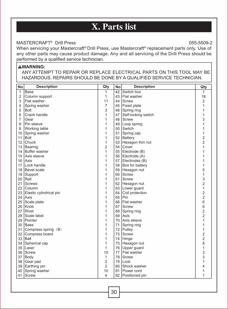
WARNING:ANY ATTEMPT TO REPAIR OR REPLACE ELECTRICAL PARTS ON THIS TOOL MAY BE HAZARDOUS. REPAIRS SHOULD BE DONE BY A QUALIFIED SERVICE TECHNICIAN.
MASTERCRAFT® Drill Press 055-5509-2When servicing your Mastercraft® Drill Press, use Mastercraft® replacement parts only. Use of any other parts may cause product damage. Any and all servicing of the Drill Press should beperformed by a qualified service technician.
X. Parts list
No1234567891011121314151617181920212223242526272829303132333435363738394041
4243444546474849505152535455565758596061626364656667686970717273747576777879808182
11117311111112111111111111111111111110122104
BaseColumn supportFlat washerSpring washerBoltCrank handleGearPin sleeveWorking tableSpring washerBoltChuckBearingBuffer washerAxis sleeveAxisLock handleBevel scaleSupportRailScrewsColumnElastic cylindrical pinAxisScale plateKnobRivetScale labelPointerBaseCompress spring(B)Compress boardBallSpherical capLaserScrewBodyGear padEarthing pinSpring washerScrew
118211131112211111513212266221112281331411
Description QtySwitch boxFlat washerScrewFixed plateSpring ringSelf-locking switchScrewLoop springSwitchSpring capBatteryHexagon thin nutCoverElectrode (B)Electrode (A)Electrodes (B)Box for batteryHexagon nutScrewScrewHexagon nutLower guardCoil protectionPinFlat washerScrewSpring ringAxisAxis sleeveSpring ringPulleyScrewHingeHexagon nutUpper guardFlat washerScrewLockShock washerPower cordPositioned pin
DescriptionNo Qty

31
X. Parts list (continued)
No83848586878889909192
93949596979899100101
2412221111
Connected axisBoltBase boardFlat washerSpring washerHexagon nutMotor pulleyBeltMotorWorm pin
213311111
Description QtyHandleBase for feed handleRail for feed handleBall for feed handleRack collarRackChuck keyAllen wrenchAllen wrench
DescriptionNo Qty

32
Imported by Mastercraft Canada Toronto, Canada M4S 2B8
11 10 9 8 7
17
22
6
2019 21
4
5
3
1
96
95
942324
(59)(4)(3)
91
89
(73)
88878685
84(3)
8382
76(43)(40) 75
(67)
(66)
647877
8062
63
676665
74(43)(36)71
70
(68)
(69)
6968
4344
61(26)6059
4951
48 46 4542 4140 39 38 37
2526
47
(13)
16
15
14
13
12
2927
28
53
81
90
54 5655 5758
(41)
52 50
30313233343536
18
79
98
99 100101
92
(61)97
72 73
2
(78)(77)
93