10 drilling killing - rgnrgn.hr/.../_private/krakow_instrumentation/10_drilling_killing.pdf · •...
TRANSCRIPT
Davorin Matanović
Control of formation pressure

Killing
• Production wells are valuable only if they permit the controlled flow of gas and oil from an underground reservoir.
• Any well that is connected to a formation where gas, oil or salt water exists under pressure may blow out control if the pressure is sufficient to raise the fluid in the well to the surface .
• An uncontrolled flow of gas, oil or salt water from a well is called a “blowout”.
• Blowouts can cause loss of life, property damage, waste of oil and gas, and damage to the producing formation.
Killing• The rig may be a total loss, and wells
may be damaged beyond salvage. • Oil and gas that escape from a well are
usually wasted and often cause serious pollution that is expensive to clean up.
• Besides the money value of oil or gas is wasted, the los of formation pressure may considerably reduce the producing capability of an oil or gas pay zone.
Killing
• The most frequent reason for killing production wells is a necessity to eliminate formation pressures so as to enable certain procedures or removal of some parts of production equipment. Sometimes, however, the killing is necessary due to some undesirable occurrences in the well (leakage or damage of the production equipment). This is known as emergency killing.
• In the process of well killing it must be taken care not to:– cause formation damage,
– additionally damage subsurface or surface production equipment,
– exceed the allowed stresses of production or other equipment.

Killing• Drilling or production rig personnel must be
alert to the hazard of a blowout; they must recognize the preliminary indications and be ready and able to close in a well to stop an impending flow. – If a blowout is to be avoided, the well head must be
closed completely, at least momentarily, to obtain pressure readings.
– Devices to shut off the well while it is being worked on are called blowout preventers.
– That are manually or hydraulically operated ram or spherical preventers, that shut of around the pipe in the well or enable complete shutoff when the pipe is out of the hole.

Killing Fluids• The zone of production can be protected from
damage if the killing fluid is properly chosen (non polluting fluid). In choosing the killing fluid it is necessary to take into account: fluid properties, well conditions, and formation parameters.
• To achieve that fluid meets its purpose at the best possible manner, the following should be take into consideration:– fluid density must comply with formation pressure,
– fluid must not have negative impact on uncovered production formation, and
– fluid must be compatible with formation fluid and formation itself.

Killing
Fluids
• At killing well, an overbalanced column must be maintained (pk>pf), and prevention of impairment requires the use of non-damaging fluid. – Damage to water-
sensitive formations may be prevented by using brine fluids (sodium, potassium and calcium chloride brines).
Density Temperature
(kg/m3) (ºC)
NaBr 1000 to 1500KCl to 1164NaCl to 1200 120 to 150CaCl2 to 1392
NaCl/CaCl2 to 1300 120 to 150CaBr2 to 1704
CaCl2/ZnBr2 1392 to 1820 >180
CaCl2/CaBr2 to 1810 >180
CaCl2/ZnCl2 to 1920 >180ZnBr2/CaBr2/CaCl2 to 2304
Oils
Diesel oil (D-1)
Crude oilPolymer systemsSaturated brine
+ polymer+ CaCO3 or FeCO3
Brine+polymer Brine density+oil soluble resinSaturated brine +polymer + sized salt
Killing fluids
Brines
840 to 230
840 to 950 > 180
150
to 1680 150
to 1620 150

Killing Fluids
• All field brines contain solids, although the amount may be very small. – In wells with low permeability reservoirs, these solids
filter out on the bore hole wall, causing a little, if any, impairment.
– In wells with medium to high permeability reservoirs, the particles are carried into the reservoir with the brine, and may cause severe impairment, because the volume of brine entering the formation is very high (owing to the lack of filtration control), although their concentration in the brine is low.
– The particles contaminating the brine may come from the source water or from the sacked salt, or they may be picked up in tank trucks or rig pits.
– A 2 micron cotton filter may reduce the content of solids.

Killing Fluids
• The killing fluid should have filter-loss control whenever necessary to prevent substantial invasion into formation. – Damage caused by killing fluid can be avoided if
all solid components of the fluid (gel plug), including filtration control agents and viscosifiers, bridging solids, and particular weighting materials are degradable.
– Various types of soluble or degradable materials are available commercially, and choice between them depends on reservoir conditions and type of operation.
Killing Fluids
• Long chain polymers are used in killing fluids to obtain rheological properties, and, in some cases, filtration control. – The bridging agents added to the suspension prevent
deep invasion of polymer into the formation.
– The bridging particle sizes must be 1/3 to 1/2 of the size of pore openings.
– The most often used polymers are hydroxyethylcellulose(HEC), derivates of guar gum and starch derivatives. HEC is almost completely soluble in acid.
– Derivatives of guar gum, such as hydroxyethyl and hydroxypropyl guar gum are degradable, leaving only 1 to 2% residue.
– Starch derivatives, such as hydroxyalkylated and esterified starches are almost completely acid soluble.

Killing Fluids
• Sized particles of oil-soluble resins or waxes may be used as bridging agents for oil reservoirs. – Any particles left in or on the formation are dissolved
when the well is brought into production.
• Ground calcium carbonate is commonly used as a bridging agent, and may be used in any type of reservoir. – It is completely soluble in acid, and on completion of the
job, it can be removed with acid if necessary.
– CaCO3 is available in a wide range of particle sizes, from several millimetres down to hundredths of micron, and may be used at any temperature encountered in an oil well.

Killing Fluids
• Density control can best be achieved with soluble salts. – Maximum densities are as follows: sodium chloride, 1200
kg/m3; calcium chloride, 1390 kg/m3; calcium bromide, 1820 kg/m3; and combined with CaCl2, 1810 kg/m
3; or with CaCl2/ZnBr2, 2300 kg/m
3.
– When the high cost of CaBr2 cannot be justified, densities up to about 1680 kg/m3 may be obtained with ground CaCO3.
– If densities greater than 1680 kg/m3 are required, they can be obtained with ferrous carbonate (siderite) -FeCO3.
– A fluid which uses sized grains of sodium chloride as bridging and weighting agents may be also used in well killing procedure.

Killing Fluids
• A fluid which uses sized grains of sodium chloride as bridging and weighting agents may be also used in well killing procedure.
– The grains are suspended in saturated brine by a polymer and a dispersant (both unspecified).
– Densities up to 1680 kg/m3 are attainable. When the well is brought into production, the salt grains are removed by formation water, or the well can be cleaned by flushing wit under saturated brines.

Killing
• The killing procedure depends on wellboreconditions and the set in production equipment.
– According to the direction of killing fluid circulation, the killing is considered direct or indirect.
– In case the fluid is injected back into the formation, it is necessary to establish the communication between the inside of the tubing and annulus after the fluid and gel have been injected, which enables a complete replacement of workover fluid when necessary.
– This communication is possible through the installed circulation tools, or by inactivating the packer, or disconnecting at the safety joint, and similar, relative to the installed production equipment.

Killing• Killing is always used in situations where:
- uncontrolled fluid flow from the well to environment exists, and there is no possibility to stop it with existing installed pressure control equipment,- when fluid under pressure enters the annular space, with the pressures that exceeded critical values of casings or wellhead spools,- when the condition of well control equipment imply that there is no possibility to shot of the well safely,- and in all other cases when it is desired to prevent any pressure effect on the well equipment and fluid invasion in the well.
Killing
• The methods for well killing can be divided into four groups considering their applications:
(1) well killing by injecting the formation fluids into production layer;
(2) circulating methods;
(3) gravitation methods;
(4) combined methods.

Well pressures
• Pressures at the bottom of the column of fluid increases as the fluid’s height becomes greater.
• This pressure is in fact dependent on the fluid density (ρ), column height (H) and the gravity (g).
• The increase of pressure with depth is termed the pressure gradient of a given fluid.
Hgph ⋅⋅= ρ

Well pressures
• The smallest pressure gradient is for fresh water;– greater is for salt water;– with the rise of the fluid density
there is the rise in pressure gradient reached with this fluid.
• For oils with various densities,there will also be the variation in pressure gradient.
• Gas of course has only a negligible pressure gradient
SPECIFIC GRAVITY
PRESSURE GRADIENT
105 Pa/m
1,00 0,0981,02 0,1011,08 0,1061,14 0,1121,20 0,1181,26 0,1241,32 0,1301,38 0,1351,44 0,1411,50 0,1471,54 0,1511,56 0,1531,62 0,1591,68 0,1651,74 0,1711,80 0,1771,86 0,1831,92 0,1881,98 0,1942,04 0,2002,10 0,2062,16 0,2122,22 0,2182,31 0,227
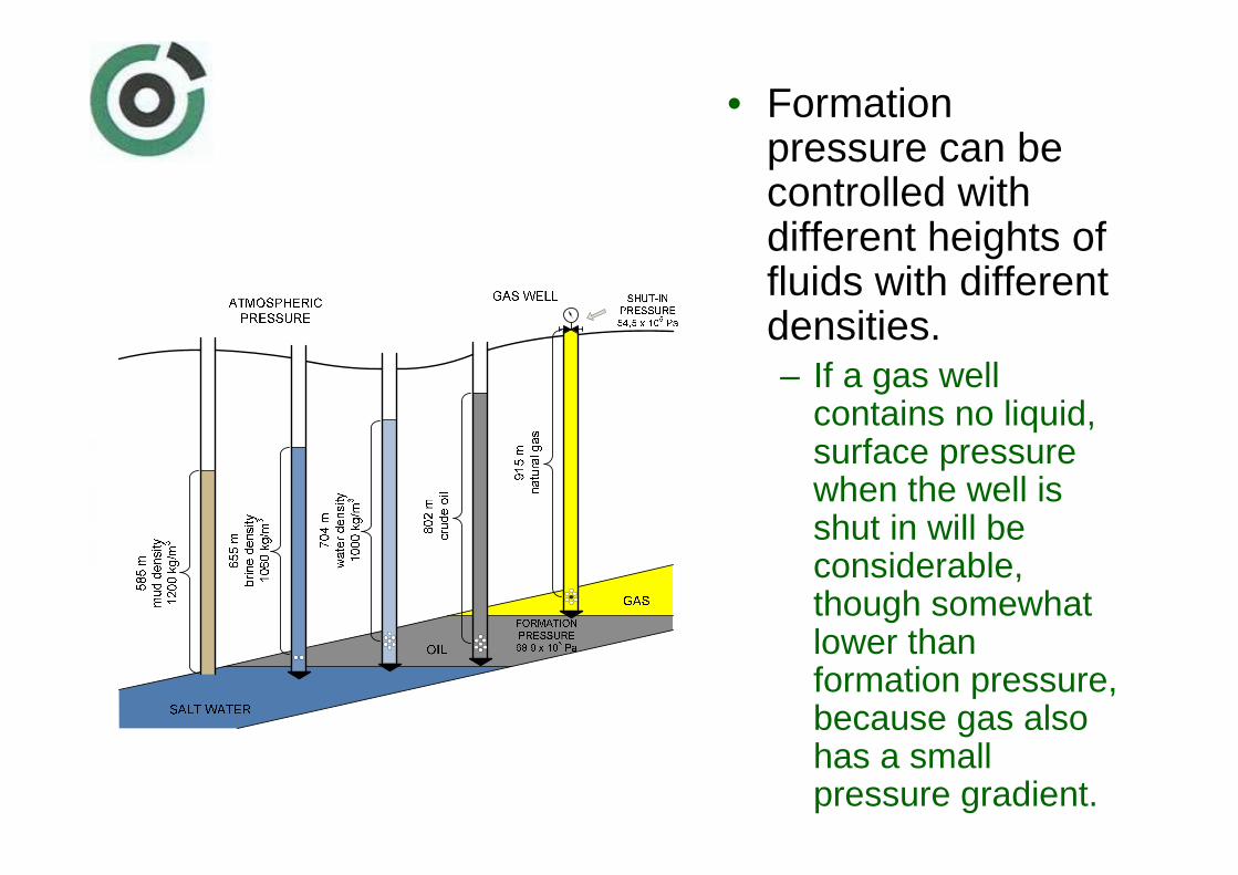
• Formation pressure can be controlled with different heights of fluids with different densities. – If a gas well
contains no liquid, surface pressure when the well is shut in will be considerable, though somewhat lower than formation pressure, because gas also has a small pressure gradient.

Principle of additive pressures
• The pressure of the fluid column in the well is called hydrostatic pressurebecause it refers to static conditions (no flow).
A B B D
D
89,6 x 10⁵
179,4 x 10⁵ Pa
269 x 105 Pa
358,8 x 10⁵
Pa 538,2 x 10⁵ Pa 269,2 x 10
5 Pa 448,4 x 10
5 Pa 448,4 x 10
5 Pa
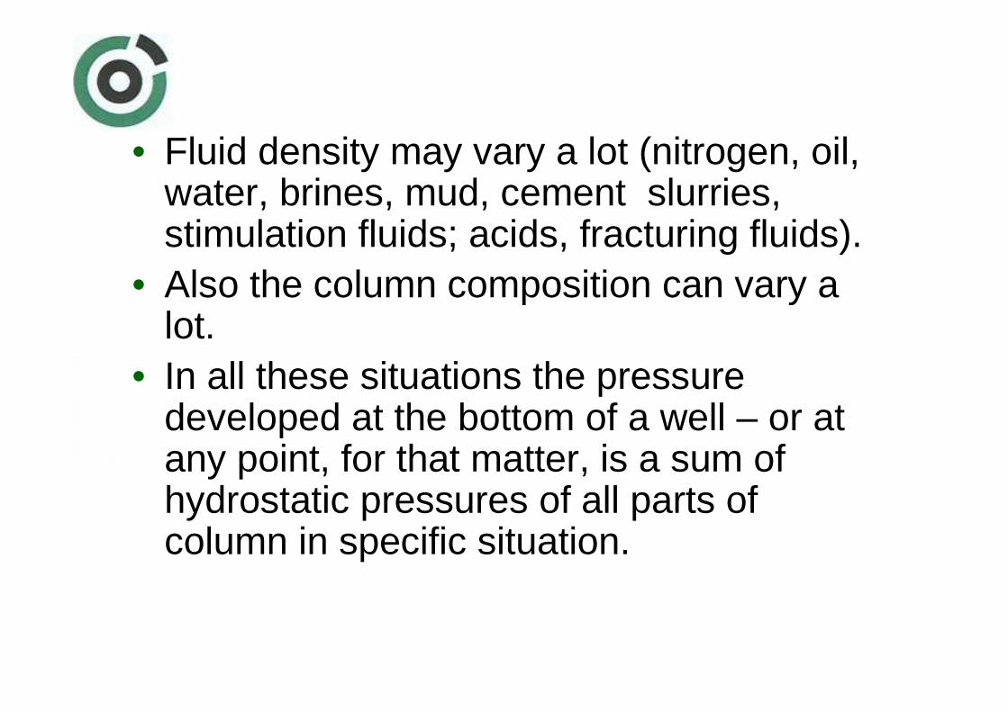
• Fluid density may vary a lot (nitrogen, oil, water, brines, mud, cement slurries, stimulation fluids; acids, fracturing fluids).
• Also the column composition can vary a lot.
• In all these situations the pressure developed at the bottom of a well – or at any point, for that matter, is a sum of hydrostatic pressures of all parts of column in specific situation.
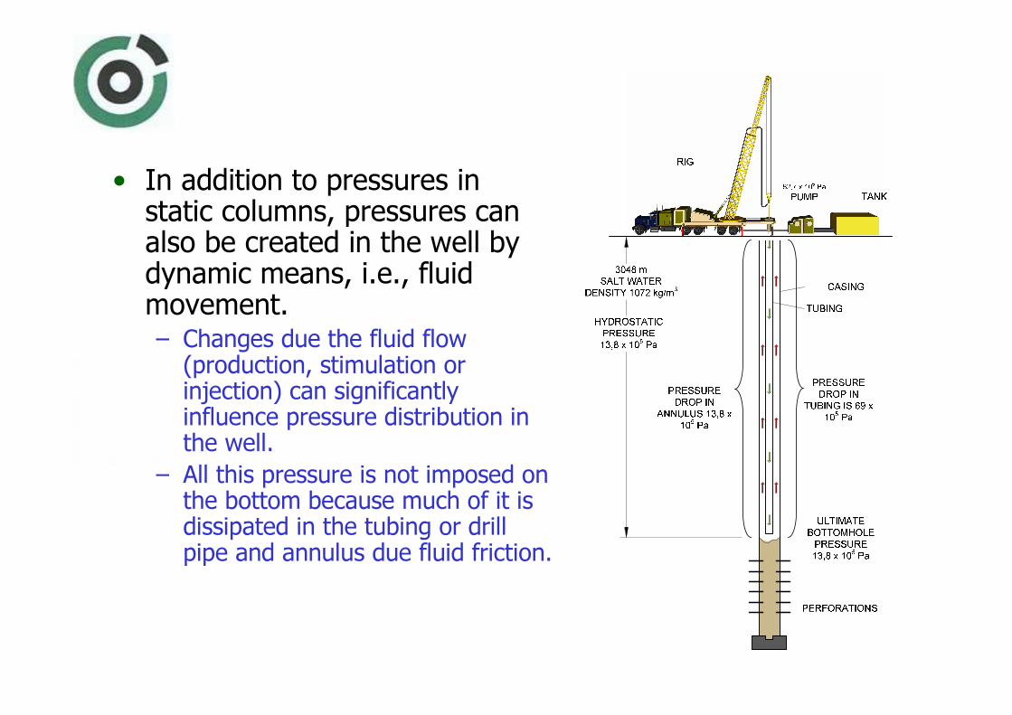
• In addition to pressures in static columns, pressures can also be created in the well by dynamic means, i.e., fluid movement. – Changes due the fluid flow
(production, stimulation or injection) can significantly influence pressure distribution in the well.
– All this pressure is not imposed on the bottom because much of it is dissipated in the tubing or drill pipe and annulus due fluid friction.

• Dynamic pressures losses are also developed by movement of pipe in a well, particularly if the fluid has considerable gel strength and viscosity. – If fluid velocity relative to inner string is
rapid, there will be greater drag than by slow movement.
– The effect is the same whether due to fluid movement by circulation, movement of the tubing or drill pipe, or both.
• Surge pressures caused by the running of pipe too fast in a well may cause formation breakdown and lost circulation.

• For the same reason, pulling pipe too fast will reduce bottom-hole pressure and may pull formation fluid into hole.– This is called “swabbing”, and in many ways,
has the same effect as a swab that is used to unload a well.
• When a long string of pipe first comes off bottom, it should be pulled slowly to minimize the swabbing effect.
• Pipe removed from a well will usually result in lower fluid level, the amount depending on the fluid displacement of the particular pipe.
• Because of that it is important to keep the hole full –that means to pump in the correct amount of fluid, equivalent to volume of the pipe body removed from the hole.

• When less fluid is required thancalculated, that it may be assumed that formation fluid has been pulled into the well by swabbing effect.– It is therefore not enough to keep the
hole full; you must be absolutely sure that the well is taking the correct amount of fluid.

• Lost returns- lost circulation, will occur when fluid is lost through open perforations or uncased hole.– This loss of fluid may be due to lack of wall cake
to seal a permeable formation , or it may be due to rupture of the rocks, which occurs when a formation is fractured.
– If lost circulation happens when a well kick is being handled, all control will be lost and a serious problem will exist.
– Fractured zones in a well must be repaired before any procedure for controlling formation pressure can be put into effect.
– Sometimes repair can be accomplished by pumping in a batch of fluid containing gel material to seal the porous formation.

Indications of a blowout• Formation pressure open to the well that is greater
than the hydrostatic pressure of the fluid column in the hole will give advance evidence of its presence to an observer. – Sometimes this evidence is very obvious; for example,
when rapid flow from the well occurs– All other times, it may be obscure and show up only as a
very slow gain of fluid in the pit. – These indicators may occur after a mechanical operation
has been performed; for example, when the casing has been perforated or after a plug has been drilled out, both of which can expose the well bore to formation pressure greater than can be controlled by the fluid column.

Some of the preliminary clues of the
blowout1. Pit level rises
as intruding gas displaces mud.
2. Bottom-hole fluid pressure drops.
1. Pit level rises faster as rate of unloading increases.
2. Gas expands as it rises in the hole.
3. Bottom-hole fluid pressure drops.
4. More gas enters well bore.
Well flow continues and accelerates as drilling fluid unloads.
1. All mud out of hole.
2. Uncontrolled gas flow – BLOWOUT!

Gas-Cut
mud
• Small quantities of gas mixed in the mud column of a well do not displace an appreciable volume of fluid, thus the hydrostatic pressure of the column is not decreased to a marked extent. – Gas expands very rapidly, as it approaches the surface, where the majority of expansion takes place.
– For this reason a little gas in the circulating fluid of a well may appear that a lot of mud weight has been lost.
SURFACE GAS VOLUME
BOTTOM
H

• Gas entry in the well bore produces serious problems for control.– Gas expands as it floats up the hole – or mud falls
through the rising gas.– But when gas is not permitted to expand; pressure
at the surface will increase as gas which retains its original bottom hole pressure rises in the hole.
Killing blowouts
• The single most important step to blowout prevention without which nothing else can be accomplished is to close the blowout preventer. – That means to stop the entry of salt water, oil or gas
into the hole; to circulate the hole to remove the contaminating fluid; and finally to replace light servicing fluid with the fluid of sufficient weight to contain the formation pressure.
– The first operation involves the use of emergency equipment – blowout preventers – to close the top of the hole, thus “to bottle up the well” to prevent further entry of formation fluids.
Killing blowouts
• All methods of blowout prevention for rotary drilling and completion make use of blowout preventer equipment and always the first step is to close in the well.
– Subsequent pressure may be too high to permit the preventers to remain closed, but this cannot be ascertained without shutting in the flow at least momentarily.
– At the first sign of an impending flow, the blowout preventer must be closed for two very important reasons:
1. To minimize entry of formation gas or fluid.2. To determine the formation pressure.

Killing blowouts
• It is not only important to close the well but it should be done at once in order to minimize the amount of formation fluids that enter the well.
18 x 105
Pa
448 x 105
Pa
PERMEABLE FORMATION
56 x 105
Pa
? ?

Killing blowouts
• If the formation pressure is known, the mud weight needed for control can be calculated. – Regardless the situation it is always possible to pump the fluid through the pipe and the annulus.
• When the formation pressure is not known; mud in the pipe is not contaminated by formation fluid, thus the pressure on the drill pipe can be used to calculate the bottom hole pressure.
18 x 105
Pa
448 x 105
Pa
PERMEABLE FORMATION
56 x 105
Pa
? ?
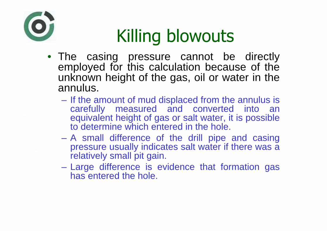
Killing blowouts• The casing pressure cannot be directly
employed for this calculation because of the unknown height of the gas, oil or water in the annulus. – If the amount of mud displaced from the annulus is
carefully measured and converted into an equivalent height of gas or salt water, it is possible to determine which entered in the hole.
– A small difference of the drill pipe and casing pressure usually indicates salt water if there was a relatively small pit gain.
– Large difference is evidence that formation gas has entered the hole.

Killing blowouts
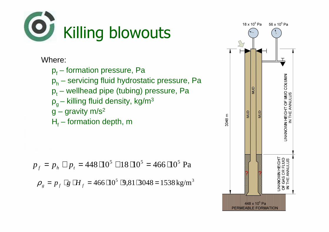
• From the picture it is obvious that only mud (servicing fluid) is in the pipe.– The formation pressure is than the sum of the hydrostatic pressure of the fluid column in the pipe, and the registered pressure inside pipe at the wellhead.
18 x 105
Pa
448 x 105
Pa
PERMEABLE FORMATION
56 x 105
Pa
? ?
Killing blowouts
Where:pf – formation pressure, Paph – servicing fluid hydrostatic pressure, Papt – wellhead pipe (tubing) pressure, Paρg – killing fluid density, kg/m3
g – gravity m/s2
Hf – formation depth, m
Pa 10466101810448 555 ⋅=⋅+⋅=+= thf ppp
35 kg/m 1538304881,910466 =⋅⋅⋅=⋅⋅= ffg Hgpρ
18 x 105
Pa
448 x 105
Pa
PERMEABLE FORMATION
56 x 105
Pa
? ?
Reduced circulating pressure
• Before the killing starts it is necessary to know the pressure drop due circulation of the fluid with the desired rate.– The recommended method for handling a well kick
makes use of a selected circulation rate.– It is obtained by running the pump at about half normal
speed; mud strokes per minute and pressures are noted and recorded for reference.
– Whole circulating system can be represented as a U-tube, where the drill pipe (tubing) is the intake side, and the annulus is the outlet to the surface.
– The greatest pressure drop is inside the pipe and bit (bit jets), and the smallest in the annulus.

• Total drill pipe pressure when circulating out a kick will be the sum of: (1) the circulating pressure at the selected pump speed, (2) the observed shut-in pressure on the drill pipe, representing the difference between formation and hydrostatic pressure, and(3) any extra pressure caused by pinching in on the choke.
448 x 105
453 x 105
5 x 10⁵
Pa
PRESSURE ON
BOTTOM DUE
TO
CIRCULATION
REDUCED
CIRCULATING
PRESSURE
SHUT-IN
STATIC
CONDITIONS
COMBINED
STATIC PLUS
CIRCULATING
PRESSURE
SERVICING
FLUID
PRESSURE
T - TUBING
PP - ANNULUST
70 x 105
Pa
PP
0 Pa
T
18 x 105
Pa
PP
56 x 105
Pa
T
88 x 105
Pa
PP
56 x 105
Pa
A B C

Reduced circulating pressure
• Pressure added on the drill pipe side of the U-tube will not necessarily be imposed on the bottom nor reach the surface on the annulus side.
• But pressure imposed by the choke will be reflected all the way to the drill pipe (tubing) gauge – though delayed.
• There will be about one second delay for each 300 m of the servicing (killing) fluid column, down the annulus and up the pipe, before pressure changes obtained by adjusting the choke on the casing appears on the drill pipe pressure gauge.

Driller’s killing method• Formation gas, oil, or salt water will flow into the
bottled-up well until total pressure at the bottom of the hole equals formation pressure. – When the closed-in pressures are stabilized, inside pipe
pressure - obtained by reading the standpipe gauge – and casing pressure, should be written down.
– Pipe pressure plus circulation pressure, are the key figure to maintain the desired constant bottom hole pressure.
– Shut-in drill pipe pressure will be used to calculate mud weight increase required to balance formation pressure.
– The closed-in casing pressure, when circulation is started, will be the starting figure for adjusting the choke on the casing outlet.
– Because of that it may be necessary to change the choke setting in order to hold the drill pipe (tubing) pressure constant.

Driller’s killing method
• The driller’s method of killing a well kick is accomplished in two circulations:
1. During first circulation, a well is circulated to remove the intruded fluid or gas from the well. – A constant bottom hole pressure is maintained to
prevent further entry of formation fluid while circulating at a reduced speed.
– Choke pressure is adjusted to hold drill pipe pressure constant.
– The circulating fluid is the same as was used when the kick was encountered.

Driller’s killing method
2. In second circulation the mud of the required density to balance formation pressure is calculated to remove and replace the lighter fluid. - Choke and pipe pressure are adjusted during this operation to maintain a constant bottom hole pressure.
Driller’s killing method• The first circulation is started by opening the
choke and simultaneously bringing the pump up to the preselected reduced speed. – Drill pipe (tubing) pressure is held constant at the figure
obtained by adding the preselected circulating pressure and shut-in pressure when the kick was encountered by regulating the casing choke.
– The driller must remember there will be a time delay between choke adjustment and the appearance of pressure increase and decrease at the standpipe.
– As an example; for a well of 3000 meters such time delay is about 20 seconds.
– Over-control, because this delay time is not recognized, has been the cause of many failures to handle a well kick properly.
Driller’s killing method
• When intruded fluid has been circulated from the well, clean fluid will appear at the casing outlet and pumping can be stopped; at that time, drill pipe and casing pressure, due to the under balance between formation and mud column pressures, should be identical.
• After heavier mud (fluid) is prepared, the second circulation can be commenced. – As the heavier fluid is circulated down the drill
pipe, casing pressure will be held constant until the drill pipe (tubing) is full.
Driller’s killing method
• Pressure control will then move back to the drill pipe until mud of the same weight fills the annulus.– When the pump is stopped well pressures
should be zero on the drill pipe and casing. – If pressure is not reduced to zero, mud
weight required to kill the well can be recalculated, mud weight increased, and the second operation repeated.

Gas wells killing in Croatia
• The structure of most gas producing wells in Croatia anticipate the method of injecting the formation fluids from the well into the production layer. All other methods have turned to be less efficient and are mostly applied to drilling phase in well construction. Killing procedure consists of the following phases:– the formation and service fluids are being injected by killing
fluid from the well bore (tubing) into the formation;– the fluid injection is terminated when the killing fluid
reaches the layer;– the static balance have to be checked at particular parts of
the well bore (tubing/annulus);– the packer fluid must be replaced if it does not meet the
required density or characteristics.

Gas wells killing in Croatia
• The injection pressure at the perforation level depends on the formation production properties, physical properties of the fluid to be injected into the formation and on the killing fluid pumping rate.
– The injection pressure at the surface also depends on the flow regime and properties of the fluid used for well killing.
• It is also necessary to be acquainted with the formation pressure sensitive range for particular volume of acceptance, as well as with the pressure values of formation fracture.
Gas wells killing in Croatia
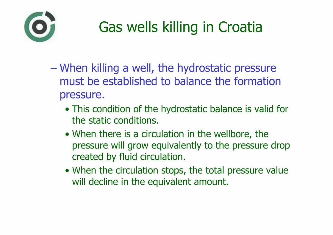
– When killing a well, the hydrostatic pressure must be established to balance the formation pressure.
• This condition of the hydrostatic balance is valid for the static conditions.
• When there is a circulation in the wellbore, the pressure will grow equivalently to the pressure drop created by fluid circulation.
• When the circulation stops, the total pressure value will decline in the equivalent amount.

Gas wells killing in Croatia
• The pressure drop when pulling out the production equipment is up to 1 MPa in the production wells of Drava Region. 10�105 Pa.– As a complementary safety value, it is necessary to over pressure the formation, which usually amounts from 10·105 to 20·105 Pa.
– The necessary killing fluid density is then derived as:
rfpfhg pppp ++=
f
rfpfg Hg
ppp
⋅++
=ρ
Where:
phg – hydrostatic pressure of killing fluid column, Pa
pr – safety value - overpressure, Pa
pfp- pressure drop created by friction when pulling out the equipment, Pa
Gas wells killing in Croatia
• The most frequent reason for killing production wells is a necessity to eliminate formation pressures so as to enable certain procedures or removal of some parts of production equipment.– Sometimes, however, the killing is necessary due to some undesirable occurrences in the well (leakage or damage of the production equipment).
– In the process of well killing it must be taken care not to:
• cause formation damage,• additionally damage subsurface or surface production
equipment,• exceed the allowed stresses of production or other equipment.

Gas wells killing in Croatia
• The over pressure can cause the loss of well killing fluid which may penetrate into formation. – To prevent this, it is necessary to inject a so called gel plug before circulating the killing fluid.
– The gel plug composition is based on well killing fluid with addition of materials for increasing viscosity and sometimes plugging material is added.
– The differential pressures that can be endured by such gels are 30·105 do 40·105 Pa of difference between the total hydraulic pressure of killing fluid and formation pressure.
– The volume of the injected gel amounts from 1 to 10 m3 and depends on the length of the uncovered interval.

Gas wells killing in Croatia
• The killing procedure depends on well bore conditions and the set in production equipment. – According to the direction of killing fluid circulation, the killing is considered direct or indirect.
– In case the fluid is injected back into the formation, it is necessary to establish the communication between the inside of the tubing and annulus after the fluid and gel have been injected, which enables a complete replacement of workover fluid when necessary.
– This communication is possible through the installed circulation tools, or by inactivating the packer, or disconnecting at the safety joint, and similar, relative to the installed production equipment.
Gas wells killing in Croatia
• Relative to the pressures at the wellhead before killing and the allowed working pressure of the equipment used in the killing procedure the fluid volume is established upon which the circulation pressure depends.
• The killing volume must be constant for the time unit in the course of the procedure.
• Pressure fluctuation during the killing procedure can cause the inflow of formation fluid into the killing fluid which may end with undesirable problems.

Bottom hole pressure during well killing
• Bottom hole pressure should remain constant all the time.
Where:pc – bottom hole circulating
pressure at defined capacity, Pa
phg – hydrostatic pressure of killing fluid column, Pa
KILLING
TIME
pc
pha
TIME
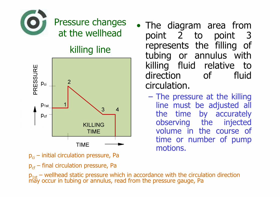
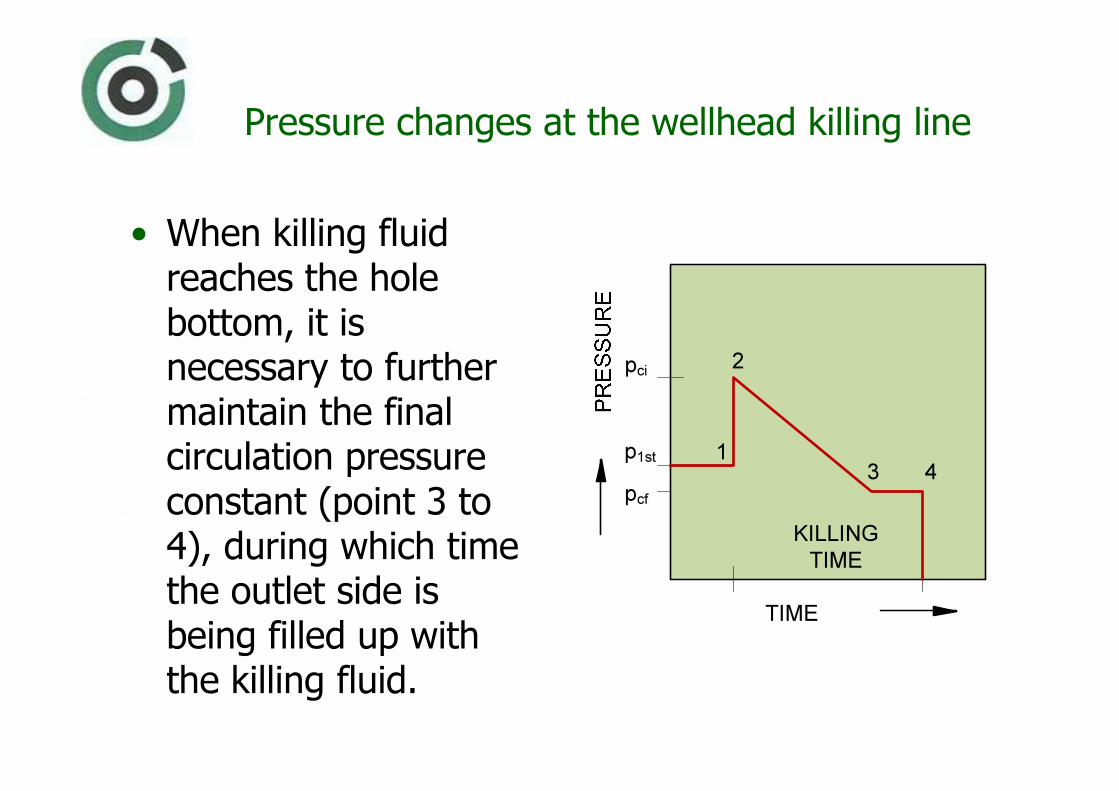
Pressure changes at the wellhead
killing line
• The diagram area from point 2 to point 3 represents the filling of tubing or annulus with killing fluid relative to direction of fluid circulation.– The pressure at the killing line must be adjusted all the time by accurately observing the injected volume in the course of time or number of pump motions.
KILLING
TIME
p1st
pcf
TIME
pci
1
2
3 4
pci
– initial circulation pressure, Pa
pcf
– final circulation pressure, Pa
p1st
– wellhead static pressure which in accordance with the circulation direction may occur in tubing or annulus, read from the pressure gauge, Pa

Pressure changes at the wellhead killing line
• The filling of tubing or annulus, overcomes the pressure in the wellhead that results from insufficient fluid pressure column as it previously existed in the wellbore.
KILLING
TIME
p1st
pcf
TIME
pci
1
2
3 4
Pressure changes at the wellhead killing line
• When killing fluid reaches the hole bottom, it is necessary to further maintain the final circulation pressure constant (point 3 to 4), during which time the outlet side is being filled up with the killing fluid.
KILLING
TIME
p1st
pcf
TIME
pci
1
2
3 4
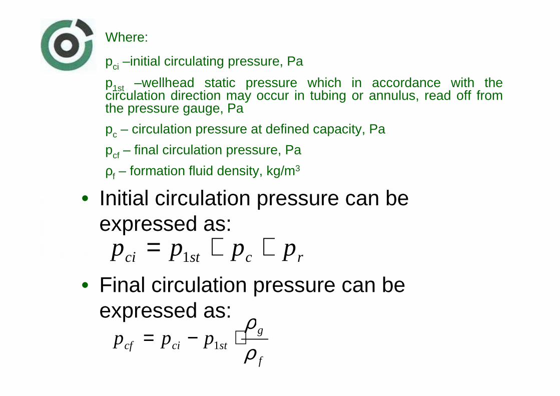
• Initial circulation pressure can be expressed as:
• Final circulation pressure can be expressed as:
rcstci pppp ++= 1
f
gstcicf ppp
ρρ
⋅−= 1
Where:
pci –initial circulating pressure, Pa
p1st –wellhead static pressure which in accordance with the circulation direction may occur in tubing or annulus, read off from the pressure gauge, Pa
pc – circulation pressure at defined capacity, Pa
pcf – final circulation pressure, Pa
ρf – formation fluid density, kg/m3

Pressure changes at the hole outlet at the wellhead
• Diagram area from point 2 to point 3 represents time of filling the upward side with maintaining the pressure at the outlet constant.
Where:
p2st
– static pressure at the fluid outflow from the hole, Pa
pr– safety value/overpressure, Pa
pchoke
– pressure drop in choke, Pa

Pressure changes at the hole outlet at the wellhead
• Area from point 3 to point 4 indicates the lifting of brine at the outlet, what reduces pressure at the surface to the point of complete fluid replacement.

Determination of Leaking Spot (Damage)
on Production Equipment
• At an ongoing production the values of pressure and temperature are constant in annulus and tubing in the wellhead.
– The abrupt disturbance of these values shows that there has been a damage on production equipment, what calls for an emergency killing.
– When possible, it is useful to locate the place of leakage on production equipment, or at least the fluid levels in the hole after the static hydraulic balance has been established.
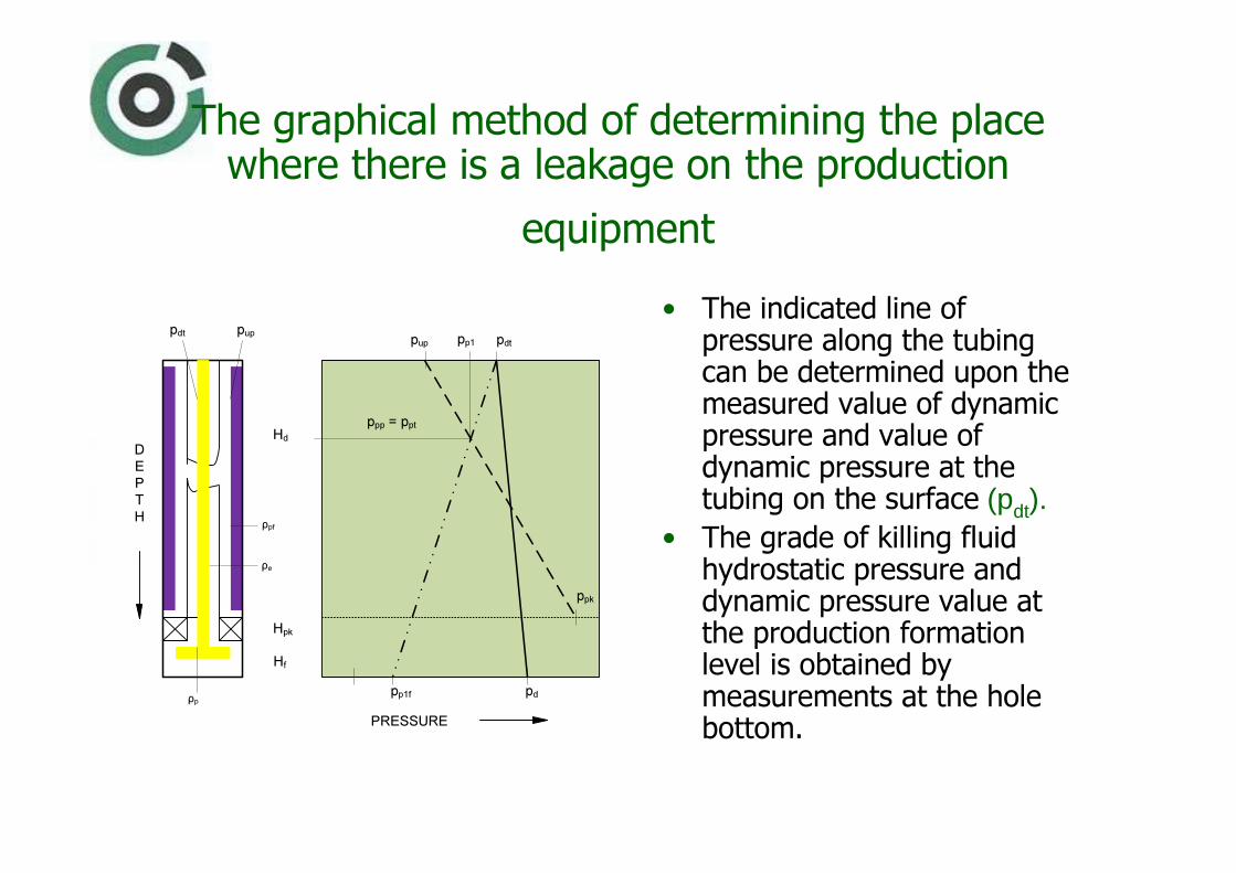
The graphical method of determining the place where there is a leakage on the production
equipment
• The indicated line of pressure along the tubing can be determined upon the measured value of dynamic pressure and value of dynamic pressure at the tubing on the surface (pdt).
• The grade of killing fluid hydrostatic pressure and dynamic pressure value at the production formation level is obtained by measurements at the hole bottom.
pup pp1 pdt
ppp = ppt
Hd
ppk
pdpp1f
PRESSURE
D
E
P
T
H
ρp
ρpf
ρe
Hpk
Hf
pdt pup
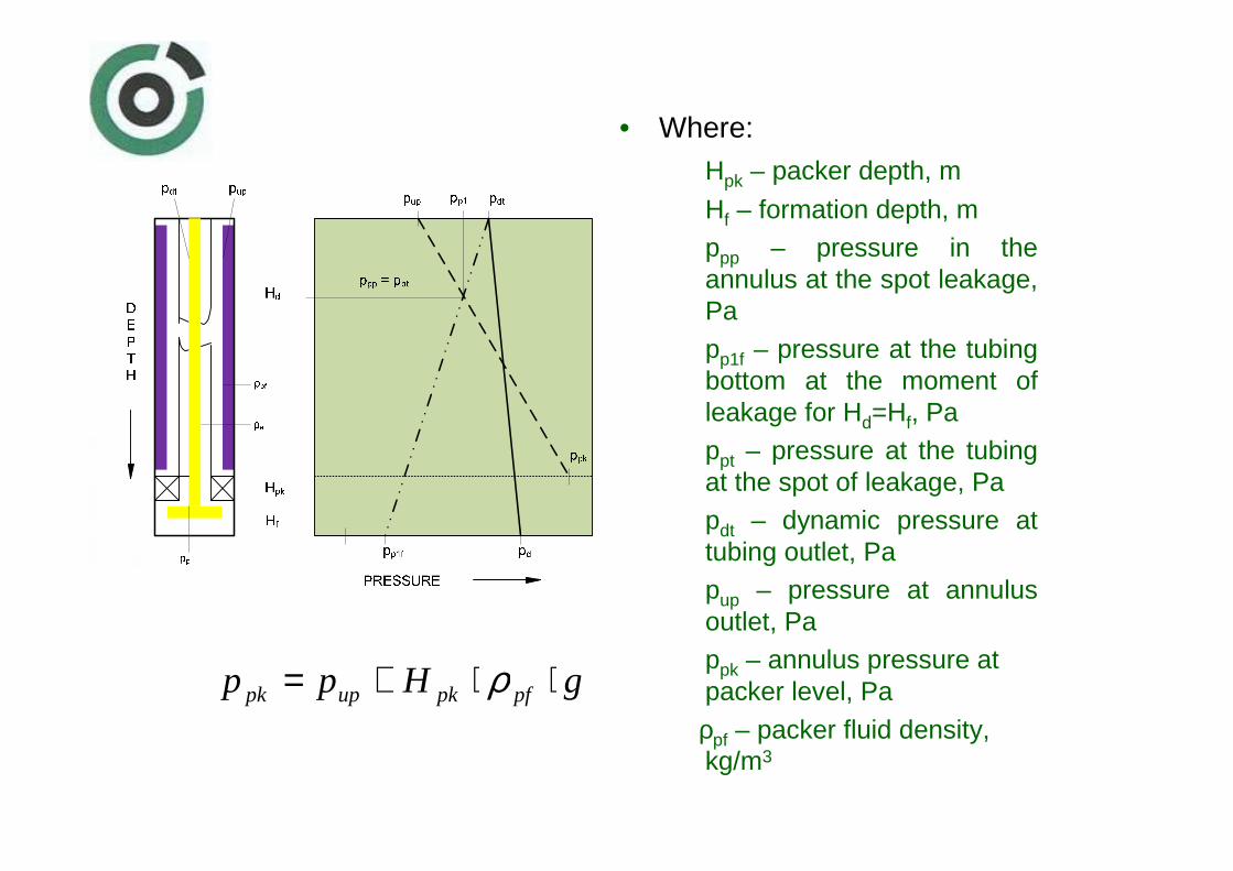
• Where:Hpk – packer depth, m
Hf – formation depth, m
ppp – pressure in the annulus at the spot leakage, Pa
pp1f – pressure at the tubing bottom at the moment of leakage for Hd=Hf, Pa
ppt – pressure at the tubing at the spot of leakage, Pa
pdt – dynamic pressure at tubing outlet, Papup – pressure at annulus outlet, Pappk – annulus pressure at packer level, Pa
ρpf – packer fluid density, kg/m3
gHpp pfpkuppk ⋅⋅+= ρ

The graphical method of determining the place where there is a leakage on the production
equipment
• The line of pressure in annulus is calculated upon the measured value at the annulus on the surface (p
ut) and the
gradient of hydrostatic pressure of packer fluid.
pup pp1 pdt
ppp = ppt
Hd
ppk
pdpp1f
PRESSURE
D
E
P
T
H
ρp
ρpf
ρe
Hpk
Hf
pdt pup

The graphical method of determining the place where there is a leakage on the production
equipment
• Production equipment leakage line is constructed based on the related pressure values in the annulus in the moment of leakage(pp1) taking in mind possible leakage level from the surface to the packer depth.
pup pp1 pdt
ppp = ppt
Hd
ppk
pdpp1f
PRESSURE
D
E
P
T
H
ρp
ρpf
ρe
Hpk
Hf
pdt pup
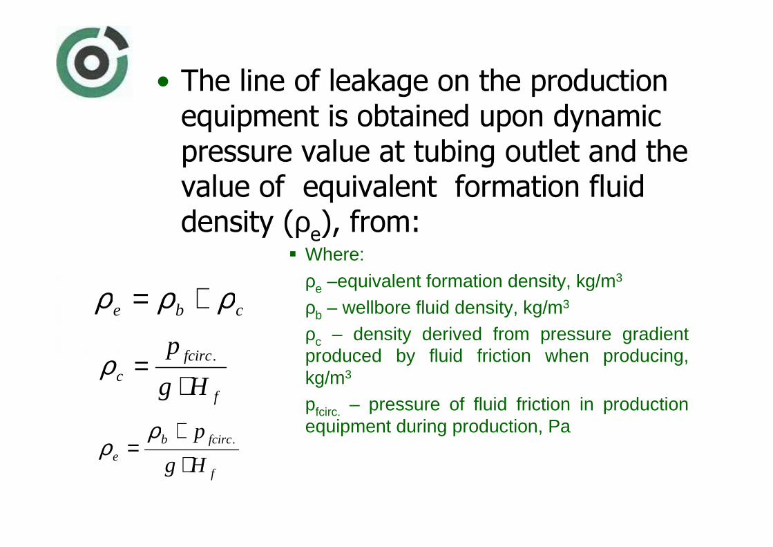
• The line of leakage on the production equipment is obtained upon dynamic pressure value at tubing outlet and the value of equivalent formation fluiddensity (ρ
e), from:
� Where:
ρe –equivalent formation density, kg/m3
ρb – wellbore fluid density, kg/m3
ρc – density derived from pressure gradient produced by fluid friction when producing, kg/m3
pfcirc. – pressure of fluid friction in production equipment during production, Pa
cbe ρρρ +=
f
fcircc Hg
p
⋅= .ρ
f
fcircbe Hg
p
⋅+
= .ρρ
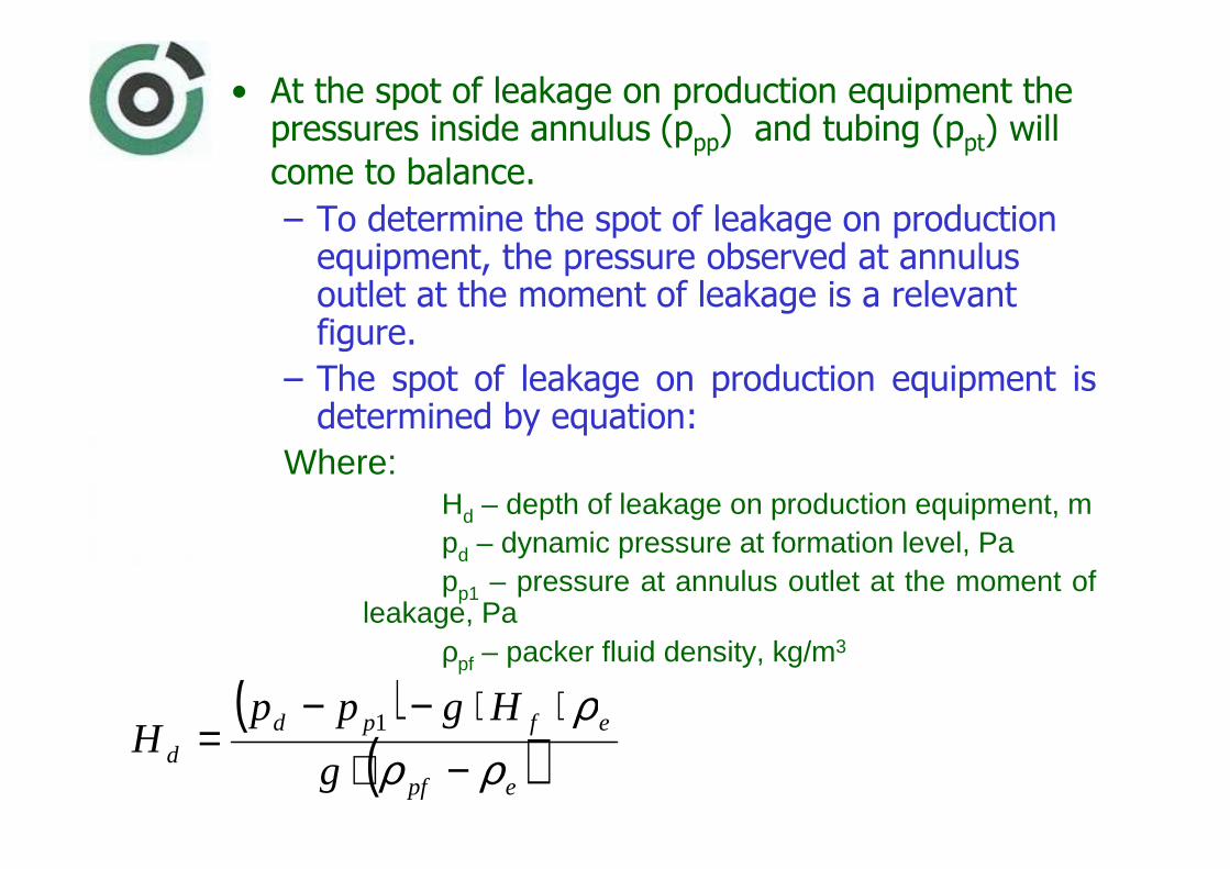
• At the spot of leakage on production equipment the pressures inside annulus (ppp) and tubing (ppt) will
come to balance.
– To determine the spot of leakage on production equipment, the pressure observed at annulus outlet at the moment of leakage is a relevant figure.
– The spot of leakage on production equipment is determined by equation:
Where:Hd – depth of leakage on production equipment, mpd – dynamic pressure at formation level, Papp1 – pressure at annulus outlet at the moment of
leakage, Paρpf – packer fluid density, kg/m3
( )( )epf
efpdd g
HgppH
ρρρ
−⋅⋅⋅−−
= 1

• The leakage line on production equipment is designed upon complementary values of annulus pressure at the moment of leakage on the equipment (pp1), for Hdam=0 and Hd=Hf:
for Hd=opp1=pdt (Pa)
for Hd=Hfpp1f=pd-g·Hf·ρpf (Pa)

• Since leakage occurs in a closed hole, the pressure changes will last until the establishment of static hydraulic balance of the fluid in the hole, which means until the gravity displacement ends.

• The pattern for determining the fluid distribution in tubing is as follows:
utfptbpftpf ppgHgH −=⋅⋅+⋅⋅ ρρ
fptpft HHH =+

• The pattern for determining distribution of fluid in casing is as follows:
fpcpfc HHH =+
upfpcbpfcpf ppgHgH −=⋅⋅+⋅⋅ ρρ
Hpft – the height of packer fluid column in tubing, m
Hpt – the height of formation fluid column in tubing, mHpfc – the height of packer fluid column in casing, m
Hpc – the height of formation fluid column in casing, m
Hf – formation depth, mput – pressure at tubing outlet, Pa
pf – formation pressure, Pa

Description of Killing Procedure of
Gas Production Well Stari Gradac-5
• Reason for killing the Stari Gradac-5production well was in the fact that formation pressure dropped, and that in order to enhance the recovery it was necessary to replace the tubing, wellhead and packer fluid.– The killing procedure method
applied in that case was injecting the formation fluid from the tubing back into the formation. The density of brine used in the killing process amounted to 1170
kg/m3.

Diagram obtained upon registered values in the killing process
1. KILLING LINE PRESSURE TESTING
2. MASTER VALVE OPENING
3. GEL PLUG INJECTION
4. KILLING FLUID INJECTION
5. GEL PLUG INJECTION THROUGH PERFORATIONS
6. PRESSURE CHECK ON TUBING HEAD 2
1 34
5
6

Diagram obtained upon registered values in the killing process
2
1 34
5
6
• For the subject well, before the separating gel plug was injected, the pressure of 15,51 MPa had been pumped up, after which the main valve was opened. – At the moment of opening the pressure at the wellhead amounted to 17,24 MPa.

Diagram obtained upon registered values in the killing process
2
1 34
5
6
• The killing started by injecting 1,3 m3 of gel which was further circulated by brine.
– In the course of injection the pressure on the pressure gauge grows due to the resistance occurring during killing fluid circulation.
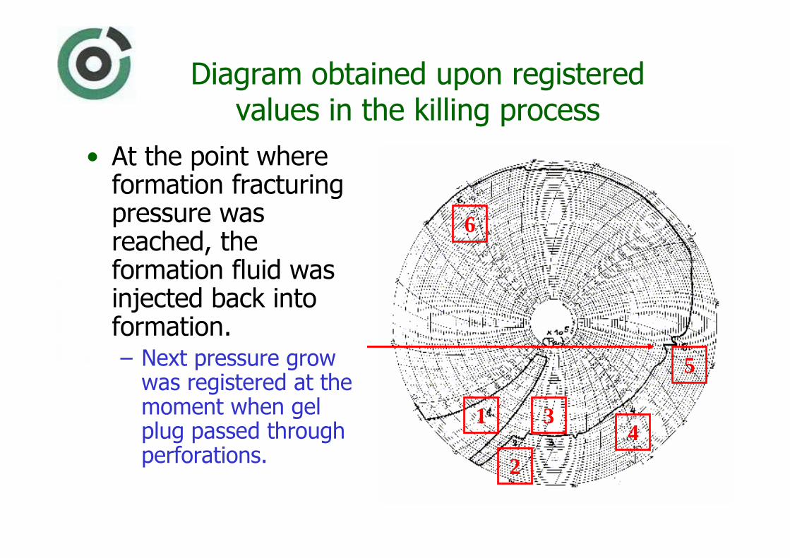
Diagram obtained upon registered values in the killing process
2
1 34
5
6
• At the point where formation fracturing pressure was reached, the formation fluid was injected back into formation. – Next pressure grow was registered at the moment when gel plug passed through perforations.
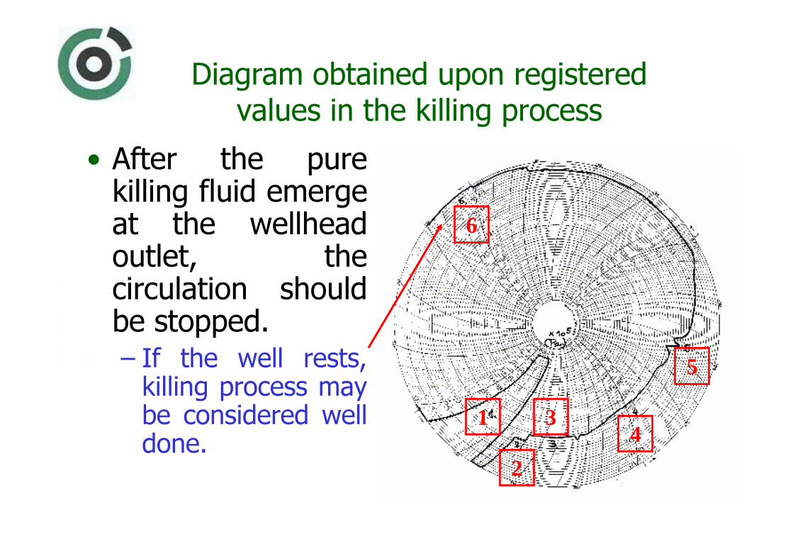
Diagram obtained upon registered values in the killing process
2
1 34
5
6
• After the pure killing fluid emerge at the wellhead outlet, the circulation should be stopped. – If the well rests, killing process may be considered well done.