10 remedial cementing
DESCRIPTION
cementingTRANSCRIPT

School of Petroleum Engineering, UNSW Open Learning - 2000
10
Remedial Placement Techniques
q Squeeze cementingØ FundamentalsØ Squeezing techniquesØ Placement techniquesØ Washing perforations
q Cement plugsØ Placement techniquesØ Cement plug design
q Job-Design Considerationsq Evaluation of the job, reasons for failures
10.1 Squeeze CementingSqueeze cementing is the process of forcing a cement slurry through holes or splits inthe casing-wellbore annular space in order to:
1. Repair a primary cement job.2. Eliminate water intrusion from above, below or within the hydrocarbon
producing zone.3. Reduce the producing gas-oil ratio (GOR) by isolating gas zones from
adjacent oil intervals.4. Repair casing leaks due to a corroded or split pipe.5. Plug all, or part, of one or more zones in a multizone injection well so as to
direct the injection into the desired intervals.6. Plug or abandon a depleted or watered-out producing zone.
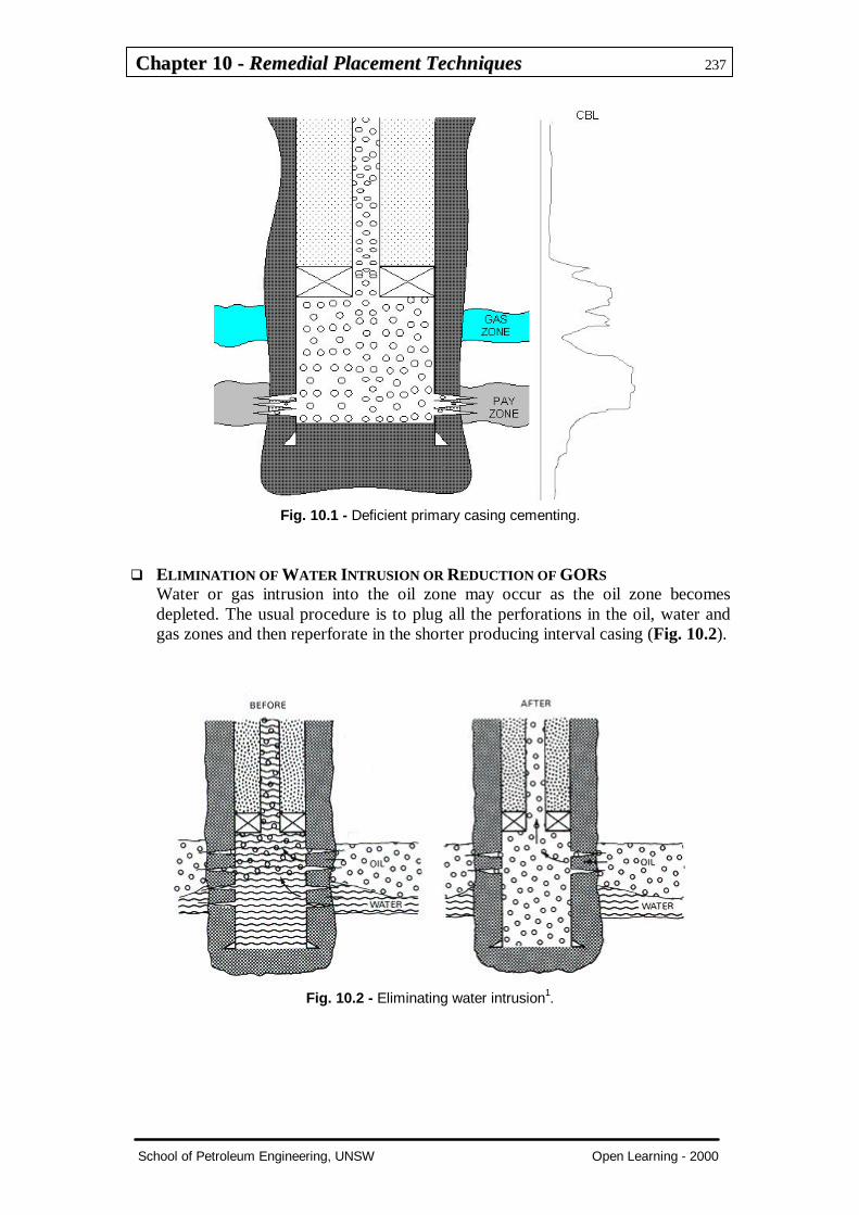
q REPAIR OF A PRIMARY CEMENT JOBPoor primary cementations are usually the cause of expensive workover jobs.Drilling mud which the cement bypasses may leave pockets or channels behindthe casing (Fig. 10.1). These channels could be cemented using either low- orhigh-pressure squeeze techniques. At low pressure, only channels connecting to apermeable formation will be cemented, since dead-end voids will not acceptcement. High-pressure squeezing may improve the cement fill-up by breakingweak walls in the set cement structure.
CChhaapptteerr 1100 -- RReemmeeddiiaall PPllaacceemmeenntt TTeecchhnniiqquueess 237
School of Petroleum Engineering, UNSW Open Learning - 2000
Fig. 10.1 - Deficient primary casing cementing.
q ELIMINATION OF WATER INTRUSION OR REDUCTION OF GORSWater or gas intrusion into the oil zone may occur as the oil zone becomesdepleted. The usual procedure is to plug all the perforations in the oil, water andgas zones and then reperforate in the shorter producing interval casing (Fig. 10.2).
Fig. 10.2 - Eliminating water intrusion1.

CChhaapptteerr 1100 -- RReemmeeddiiaall PPllaacceemmeenntt TTeecchhnniiqquueess 238
School of Petroleum Engineering, UNSW Open Learning - 2000
q PLUGGING OF ZONES OR PERFORATIONS IN MULTI-ZONE INJECTION WELLSDiversion of injection fluids, water, polymer solutions or gas is difficult toaccomplish. If no vertical permeability exists between the zones and the isolationof zones is satisfactory, the plugging of perforations in high-permeability zoneswill direct the injected fluids to the others (Fig. 10.3).
Fig. 10.3 - Diversion of injection fluids1.
q PLUG AND ABANDONMENTThis job is usually performed at low pressure to avoid damaging a zone whichmay be economically exploitable in the future.
10.1.1 FundamentalsRegardless of the techniques used, the placement of cement into fractures using high-pressure squeezing, or into the casing perforations using low-pressure squeezing, isbasically a filtration process.
Cement slurries, which are subject to differential pressure against a filter of permeablerock, lose part of their mix water, leaving a cake of partially dehydrated cementparticles (Fig. 10.4). The rate of cake buildup is a function of formation permeability,differential pressure applied and the capacity of the slurry to lose fluid.

CChhaapptteerr 1100 -- RReemmeeddiiaall PPllaacceemmeenntt TTeecchhnniiqquueess 239
School of Petroleum Engineering, UNSW Open Learning - 2000
Fig. 10.4 - Filter cake build-up into a perforation channel.
HESITATION SQUEEZEBuilding up filter cake inside perforation tunnels, or into previously induced fractures,requires the same basic procedure of applying a differential pressure to induce slurrydehydration.
The relatively small amount of filtrate lost from the slurry makes impractical, not tosay impossible, continuous pumping slow enough to replace the volume lost to theformation, and the maintaining of a constant differential pressure.
The only procedure that makes the dehydration of small quantities of cement intoperforations or formation cavities possible is the intermittent application of pressure,separated by a period of pressure leak-off caused by the loss of filtrate into theformation. The initial leak-off is usually fast, because there is no filter cake. This willallow, at the beginning of the job, short periods between pumping stages (Fig. 10.5).
Fig. 10.5 - Typical hesitation-squeeze pressure behaviour2.

CChhaapptteerr 1100 -- RReemmeeddiiaall PPllaacceemmeenntt TTeecchhnniiqquueess 240
School of Petroleum Engineering, UNSW Open Learning - 2000
As the filter cake builds up, the filtration periods become longer and the differencebetween initial and final pressures smaller, until, at the end of the job, the pressureleak-off becomes negligible. At this stage, a pressure test of 300 to 500 psi over thefinal injection pressure followed by a constant, zero slope, will indicate the end of thedehydration process. The pressure test usually lasts between ten and fifteen minutesand will not indicate the success of the job, only that open perforations will not acceptmore fluid.
10.1.2 Squeezing Techniques
q LOW-PRESSURE SQUEEZINGCement slurry is forced through the perforations at pressures below the formationfracturing pressure. The aim if to fill perforation cavities and interconnected voidswith dehydrated cement.
The volume of cement required for this operation is relative small, since no slurryis actually pumped into the formation. If a large volume of slurry is used, thehydrostatic pressure created by the long column of cement slurry will, in mostcases, breakdown the formation with no evident surface indication.
When squeezing perforations in depleted formations, spotting the total volume ofcement in front of the perforations may be the only way to prevent the formationfrom fracturing as a result of hydrostatic pressure.
If ‘bull-head’ squeezing is to be performed the following calculations areapplicable (Fig. 10.6).
Fig. 10.6 - 'Bull-head' squeezing.

CChhaapptteerr 1100 -- RReemmeeddiiaall PPllaacceemmeenntt TTeecchhnniiqquueess 241
School of Petroleum Engineering, UNSW Open Learning - 2000
Maximum allowable pressure at perfs = Fracturing pressure minus 500 psi safety factor
]500)[(]}[][]){[(052.0 −×=++−− hFGkXkXh csc ρρρ (10.1)
hence, ][052.0
]052.0[]500)[(
cs
chhFGX
ρρρ
−−−×=
This value, X, represents the maximum column of cement the formation canwithstand. The maximum volume of cement slurry is therefore:
)(max tXVV = (10.2)
where h = perforation depth, ftX = length of cement column, ftρs = slurry density, lb/galρc = completion fluid density, lb/galFG = formation fracture gradient, psi/ft0.052 = conversion factor, lb/gal to psi/ftVt = tubing volume per unit length, cu.ft./ftk = distance from packer to perforations, ft
Example 10.1Perforations to be squeezed off at 6250 ft through a 2½’’ ID tubing inside 7’’ (30 lb/ft) casing.Packer to be set at 6150 ft.
Estimated frac gradient = 0.7 psi/ftDisplacement fluid = 8.6 lb/gal brineCement slurry = Class G + 0.2 gal/sk FLAC D603 + 0.1 gal/sk TIC D80
density = 15.8 lb/galyield = 1.15 cu.ft./sk
Using Eqs. (10.1) and (10.2), we obtain:
]6.88.15[052.0]6.86250052.0[]500)62507.0[(
−××−−×=X = 2885 ft
so,
Vmax = 2885 x 0.0325 = 93.75 cu.ft
or, in terms of sacks of cement
= 80 sk
which is surely a sufficient volume for cementing 20 ft of perforated casing. If the interval islarge and more cement is necessary, a lighter slurry must be used or the cement must bespotted.
CChhaapptteerr 1100 -- RReemmeeddiiaall PPllaacceemmeenntt TTeecchhnniiqquueess 242
School of Petroleum Engineering, UNSW Open Learning - 2000
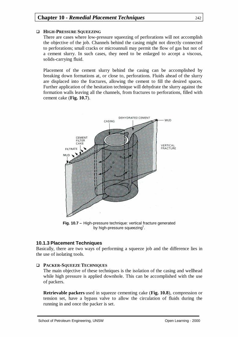
q HIGH-PRESSURE SQUEEZINGThere are cases where low-pressure squeezing of perforations will not accomplishthe objective of the job. Channels behind the casing might not directly connectedto perforations; small cracks or microannuli may permit the flow of gas but not ofa cement slurry. In such cases, they need to be enlarged to accept a viscous,solids-carrying fluid.
Placement of the cement slurry behind the casing can be accomplished bybreaking down formations at, or close to, perforations. Fluids ahead of the slurryare displaced into the fractures, allowing the cement to fill the desired spaces.Further application of the hesitation technique will dehydrate the slurry against theformation walls leaving all the channels, from fractures to perforations, filled withcement cake (Fig. 10.7).
Fig. 10.7 – High-pressure technique: vertical fracture generatedby high-pressure squeezing1.
10.1.3 Placement TechniquesBasically, there are two ways of performing a squeeze job and the difference lies inthe use of isolating tools.
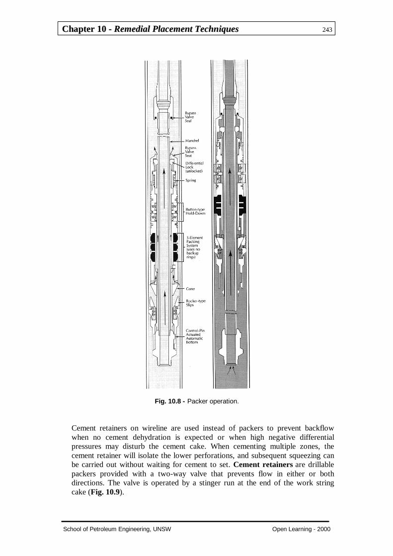
q PACKER-SQUEEZE TECHNIQUESThe main objective of these techniques is the isolation of the casing and wellheadwhile high pressure is applied downhole. This can be accomplished with the useof packers.
Retrievable packers used in squeeze cementing cake (Fig. 10.8), compression ortension set, have a bypass valve to allow the circulation of fluids during therunning in and once the packer is set.
CChhaapptteerr 1100 -- RReemmeeddiiaall PPllaacceemmeenntt TTeecchhnniiqquueess 243
School of Petroleum Engineering, UNSW Open Learning - 2000
Fig. 10.8 - Packer operation.
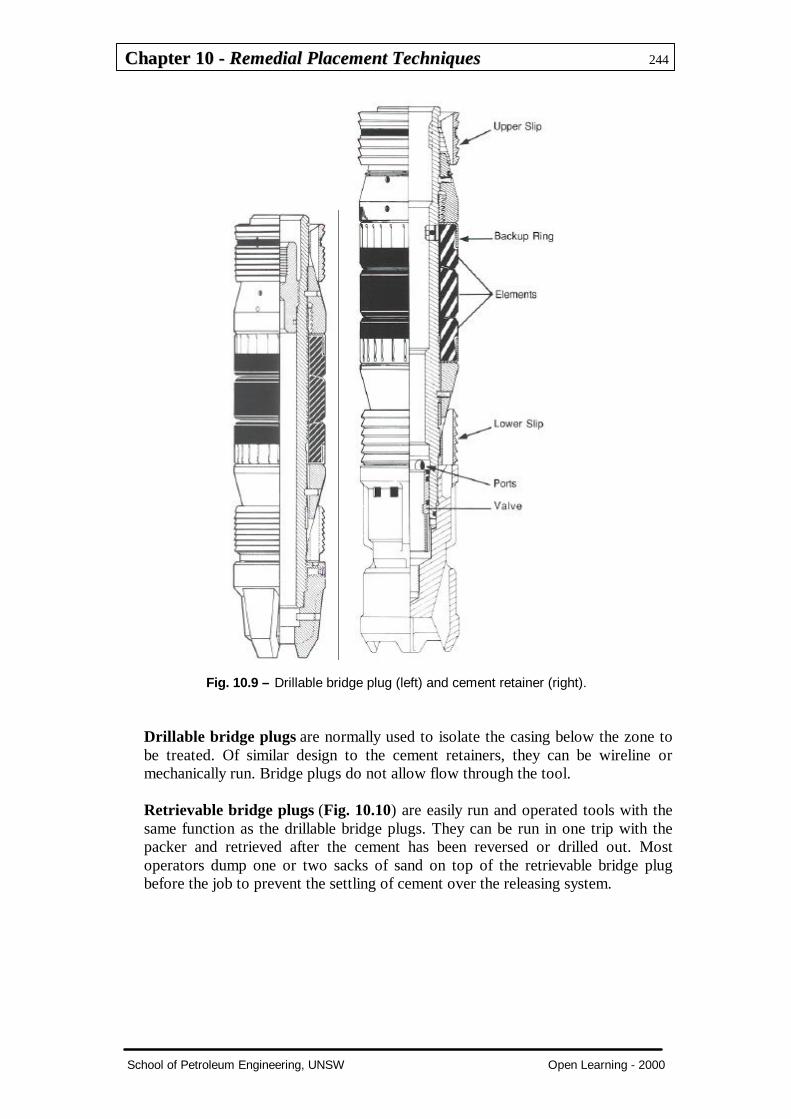
Cement retainers on wireline are used instead of packers to prevent backflowwhen no cement dehydration is expected or when high negative differentialpressures may disturb the cement cake. When cementing multiple zones, thecement retainer will isolate the lower perforations, and subsequent squeezing canbe carried out without waiting for cement to set. Cement retainers are drillablepackers provided with a two-way valve that prevents flow in either or bothdirections. The valve is operated by a stinger run at the end of the work stringcake (Fig. 10.9).
CChhaapptteerr 1100 -- RReemmeeddiiaall PPllaacceemmeenntt TTeecchhnniiqquueess 244
School of Petroleum Engineering, UNSW Open Learning - 2000
Fig. 10.9 – Drillable bridge plug (left) and cement retainer (right).
Drillable bridge plugs are normally used to isolate the casing below the zone tobe treated. Of similar design to the cement retainers, they can be wireline ormechanically run. Bridge plugs do not allow flow through the tool.
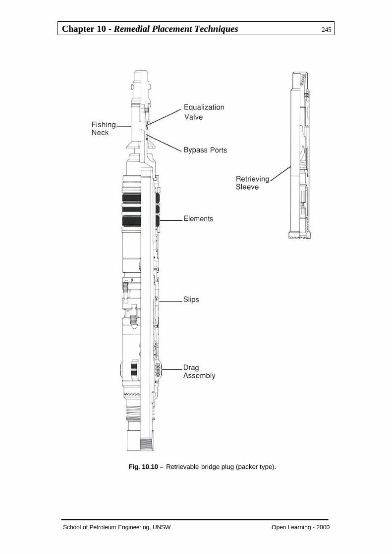
Retrievable bridge plugs (Fig. 10.10) are easily run and operated tools with thesame function as the drillable bridge plugs. They can be run in one trip with thepacker and retrieved after the cement has been reversed or drilled out. Mostoperators dump one or two sacks of sand on top of the retrievable bridge plugbefore the job to prevent the settling of cement over the releasing system.
CChhaapptteerr 1100 -- RReemmeeddiiaall PPllaacceemmeenntt TTeecchhnniiqquueess 245
School of Petroleum Engineering, UNSW Open Learning - 2000
Fig. 10.10 – Retrievable bridge plug (packer type).

CChhaapptteerr 1100 -- RReemmeeddiiaall PPllaacceemmeenntt TTeecchhnniiqquueess 246
School of Petroleum Engineering, UNSW Open Learning - 2000
BASIC JOB PROCEDURES1. Lower zones are isolated by a retrievable or drillable bridge plugs.
2. Perforations are washed using a perforation wash tool or they are re-opened bysurging.
3. The wash tool is retrieved and the packer run in the hole with the work string,set at the desired depth and tested. The packer is run with or without a tailpipe,depending on the operation to be performed. If cement is to be spotted in frontof the perforations, a tailpipe that covers the length of the zone plus 10 to 15feet must be run with the packer.
4. An injectivity test is performed using clean, solids-free water or brine. Thistest will give an idea of the permeability of the formation to the cementfiltrate.
5. The spearhead or breakdown fluid followed by the cement slurry is circulateddownhole with the packer by-pass open. This is done to avoid the squeezing ofdamaging fluids ahead of the slurry. A small amount of back-pressure must beapplied on the annulus to prevent the slurry fall caused by U-tubing. If notailpipe has been run, the packer by-pass must be closed 2 or 3 bbl before theslurry reaches the packer. If the cement is to be spotted in front of theperforations, with the packer unset, circulation is stopped as soon as thecement covers the desired zone, the tailpipe pulled out of the cement slurryand the packer set at the desired depth.
If tailpipe is run, the minimum distance between perforations and packer islimited to the length of the tailpipe. The packer must not be set too close to theperforations as pressure communication through the annulus above the packermight cause the casing to collapse.
Casing conditions and possible cement contamination limit the maximumspacing between packer and the treated zone (Figs. 10.11 and 10.12).
6. Squeeze cementing is applied at the surface. If high-pressure squeezing isemployed, the formation is broken down and the cement slurry pumped intothe fractures before the hesitation technique is applied. If low-pressuresqueezing is desired, hesitation is started as soon as the packer is set.
7. Pressure is released and returns are checked. If no returns are noticed, thepacker by-pass is opened and excess cement reversed out. Washing off cementin front of the perforations can be performed by releasing the packer andslowly lowering the work string during the reversing.
8. Tools are pulled out and the cement is left to cure for the recommended time,usually 4 to 6 hours.
9. Hesitation continues until no pressure leak-off is observed. A further test ofabout 500 psi over the final injection pressure will indicate the injectionprocess.

CChhaapptteerr 1100 -- RReemmeeddiiaall PPllaacceemmeenntt TTeecchhnniiqquueess 247
School of Petroleum Engineering, UNSW Open Learning - 2000
30 - 100 ft
Fig. 10.11 - Retrievable packer near perforations.
RUNNING TAILPIPE BELOWPERFORATIONS
CEMENT SPOTTING SQUEEZING PERFORATIONSAFTER SETTING PACKER AND
TAILPIPE ABOVE CEMENT
Fig. 10.12 - Retrievable packer with tail pipe.

CChhaapptteerr 1100 -- RReemmeeddiiaall PPllaacceemmeenntt TTeecchhnniiqquueess 248
School of Petroleum Engineering, UNSW Open Learning - 2000
q BRADENHEAD SQUEEZEThis technique is used mainly when the low-pressure squeezing is practiced andthere are no doubts about the casing’s capacity to withstand the squeeze pressures.There no special tools involved, besides the bridge plug to isolate downholeformations.
Open-ended tubing is run to the bottom of the zone to be cemented. BOP rams areclosed over the tubing and the injection test carried out as usual. The cementslurry is subsequently spotted in front of the perforations. Once the cement is inplace, the tubing is withdrawn to a point above the cement top, the preventers areclosed and the hesitation technique applied through the tubing. Reversing orwashing down is carried out as normal (Fig. 10.13).
SPOT CEMENT APPLICATION OF SQUEEZEPRESSURE
REVERSE CIRCULATION
Fig. 10.13 - Bradenhead squeeze technique is normally used on low-pressure formations.Cement is circulated into place down drillpipe (left), then wellhead, or BOP, isclosed (center) and squeeze pressure is applied. Reverse circulating (right)removes excess cement, or plug can be drilled out.

CChhaapptteerr 1100 -- RReemmeeddiiaall PPllaacceemmeenntt TTeecchhnniiqquueess 249
School of Petroleum Engineering, UNSW Open Learning - 2000
10.1.4 Washing PerforationsThe most common reason for high- and low-pressure squeezing failure is pluggedperforations.
q PERFORATION WASH TOOLA perforation wash tool isolates a small number of perforations at a time (Fig.10.13). A wash fluid is pumped down the tubing, forced into the holes, thenoutside the casing and back through higher perforations into the annulus. Slowlythe tool can be moved to cover the entire zone. Fluids used for washing varyaccording to the material damaging the perforation tunnels.
Fig. 10.14 - A perforation washing tool2.

CChhaapptteerr 1100 -- RReemmeeddiiaall PPllaacceemmeenntt TTeecchhnniiqquueess 250
School of Petroleum Engineering, UNSW Open Learning - 2000
q MATRIX ACIDISINGAcidising perforations with hydrochloric or hydrofluoric acid solutions is anothereffective method of removing acid soluble materials. The acid is injected throughthe perforations into the formation using ball sealers or chemical diverters toaccomplish a homogeneous distribution across the zone. The acid must be flowedback after spending or, if formation damage is not a major concern, it can bedisplaced further into the rock by overflushing.
q BACK SURGINGA surge tool is basically a tubing air chamber between upper and lower valves.The necessary volume at atmospheric pressure is calculated based on the numberof perforations.
The tool is run in the hole with a packer in order to isolate the desired zone. A by-pass valve is run on top of the valve to allow circulation during running in thehole.
Once the packer is set, the lower valve, which is operated by pressure applied onthe annulus (1000 psi) is opened allowing fluid into the air chamber. The rapiddepressurisation of the borehole will create high differential pressure across theperforations and the subsequent removal of material from them by the formationfluid. To establish circulation after back surging, the upper valve is opened bytubing pressure, tubing turn, or by rupturing a disc with a metal bar. Debris andforeign materials are then reversed out of the hole (Fig. 10.15).
UPPER MECHANICALDISK VALVE
HYDRAULICALLYOPERATED SURGE VALVE
PACKER
Fig. 10.15 - Perforation surge tool.

CChhaapptteerr 1100 -- RReemmeeddiiaall PPllaacceemmeenntt TTeecchhnniiqquueess 251
School of Petroleum Engineering, UNSW Open Learning - 2000
10.2 Cement PlugsThere are many reasons for setting a cement plug, such as:
1. To cure lost circulation during drilling.2. Abandoning a well.3. Shutting of water.4. Providing a seat for a whipstock to sidetrack a plugged part of the hole (Fig.
10.16).5. Plugging back a depleted zone (Fig. 10.17).
Fig. 10.16 - Sidetracking/whipstocking.
Fig. 10.17 - Plugging back of depleted zones.

CChhaapptteerr 1100 -- RReemmeeddiiaall PPllaacceemmeenntt TTeecchhnniiqquueess 252
School of Petroleum Engineering, UNSW Open Learning - 2000
10.2.1 Placement TechniquesCommon techniques to place cement plugs are:
1. Balanced plug.2. Dump bailing.
q BALANCED PLUGThis is the most commonly used. Drillpipe or tubing is run in the hole as far as thedesired plug’s base. Spacer or wash is pumped ahead and behind to avoid mudcontamination. Displacement is completed to the top of the calculated plug length(pipe inside plug) and allowed to reach hydrostatic balance. It is common practiceto underdisplace 2 to 3 bbl to avoid flow-back onto the rig-floor during trippingout.
Once the plug is balanced, the pipe is slowly pulled out to the plug’s desired topdepth and any excess of cement circulated out of the hole (Fig. 10.18).
Fig. 10.18 - Balanced plug.
CChhaapptteerr 1100 -- RReemmeeddiiaall PPllaacceemmeenntt TTeecchhnniiqquueess 253
School of Petroleum Engineering, UNSW Open Learning - 2000
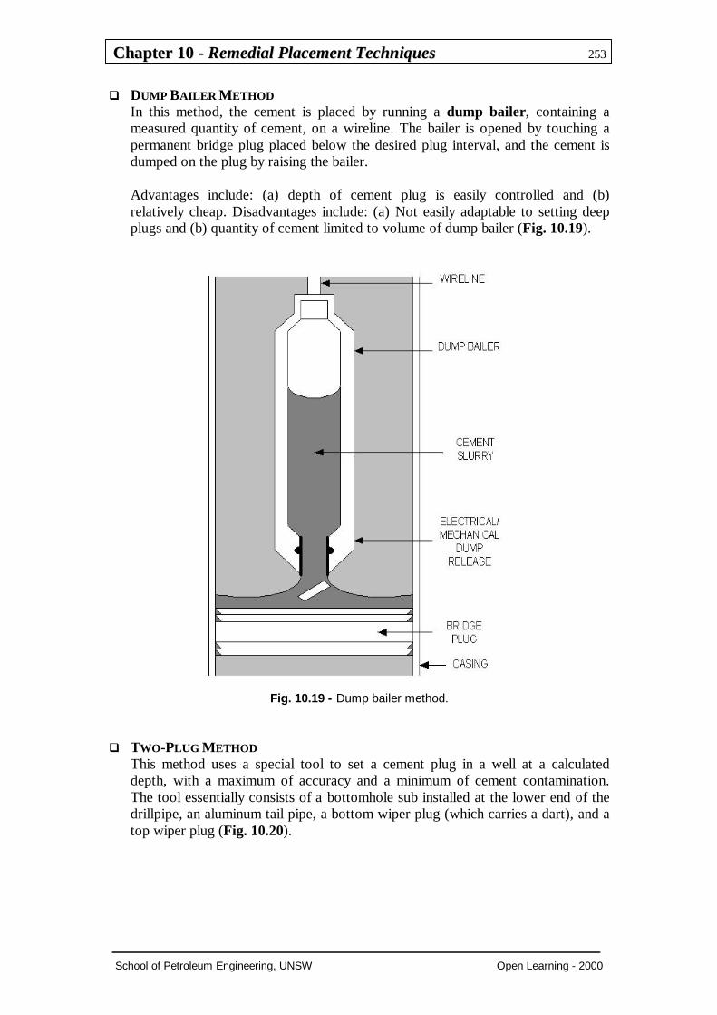
q DUMP BAILER METHODIn this method, the cement is placed by running a dump bailer, containing ameasured quantity of cement, on a wireline. The bailer is opened by touching apermanent bridge plug placed below the desired plug interval, and the cement isdumped on the plug by raising the bailer.
Advantages include: (a) depth of cement plug is easily controlled and (b)relatively cheap. Disadvantages include: (a) Not easily adaptable to setting deepplugs and (b) quantity of cement limited to volume of dump bailer (Fig. 10.19).
Fig. 10.19 - Dump bailer method.
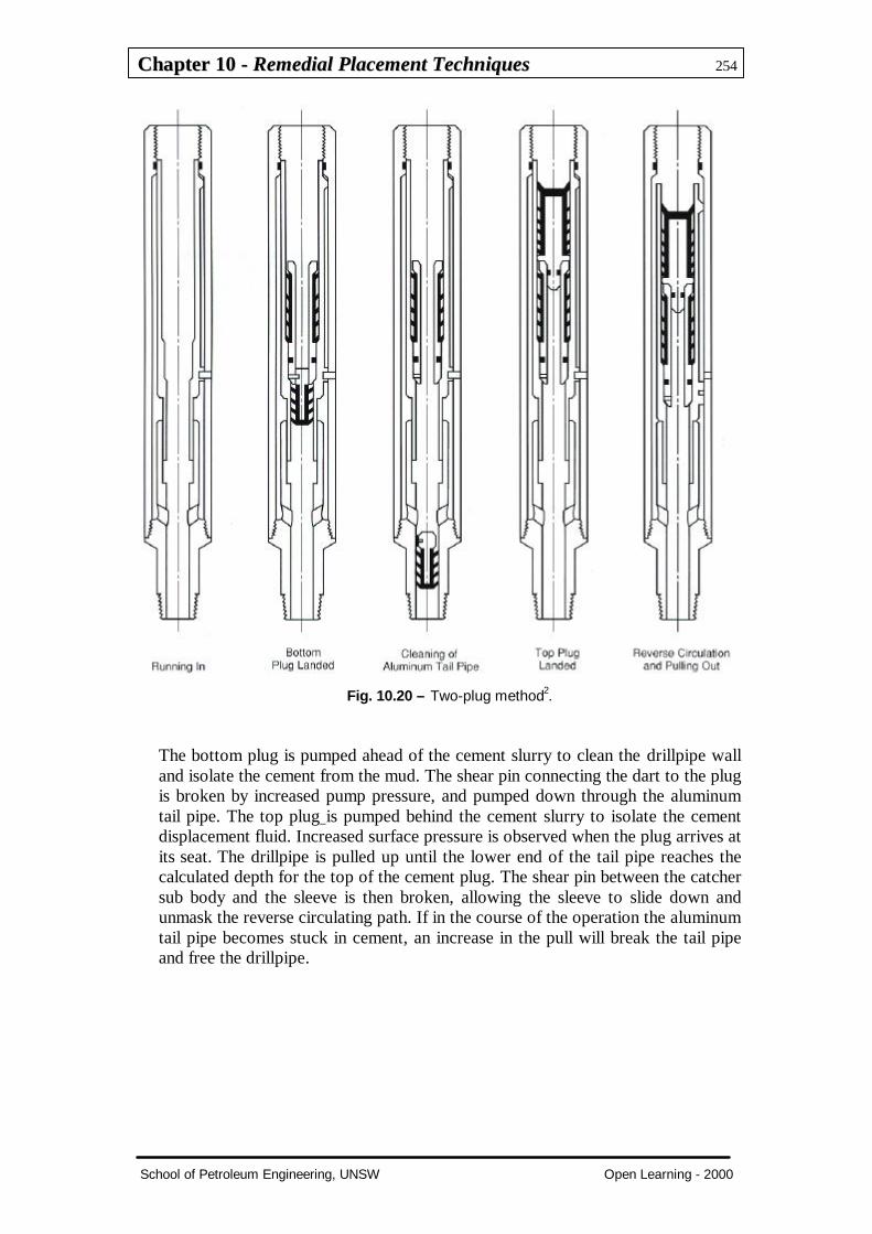
q TWO-PLUG METHODThis method uses a special tool to set a cement plug in a well at a calculateddepth, with a maximum of accuracy and a minimum of cement contamination.The tool essentially consists of a bottomhole sub installed at the lower end of thedrillpipe, an aluminum tail pipe, a bottom wiper plug (which carries a dart), and atop wiper plug (Fig. 10.20).
CChhaapptteerr 1100 -- RReemmeeddiiaall PPllaacceemmeenntt TTeecchhnniiqquueess 254
School of Petroleum Engineering, UNSW Open Learning - 2000
Fig. 10.20 – Two-plug method2.
The bottom plug is pumped ahead of the cement slurry to clean the drillpipe walland isolate the cement from the mud. The shear pin connecting the dart to the plugis broken by increased pump pressure, and pumped down through the aluminumtail pipe. The top plug is pumped behind the cement slurry to isolate the cementdisplacement fluid. Increased surface pressure is observed when the plug arrives atits seat. The drillpipe is pulled up until the lower end of the tail pipe reaches thecalculated depth for the top of the cement plug. The shear pin between the catchersub body and the sleeve is then broken, allowing the sleeve to slide down andunmask the reverse circulating path. If in the course of the operation the aluminumtail pipe becomes stuck in cement, an increase in the pull will break the tail pipeand free the drillpipe.
CChhaapptteerr 1100 -- RReemmeeddiiaall PPllaacceemmeenntt TTeecchhnniiqquueess 255
School of Petroleum Engineering, UNSW Open Learning - 2000
10.2.2 Cement Plug DesignThe design of cement plugs is closely related to the objectives of the plug. Some ofthe key factors to consider are:
1. Cement volume.2. Cement slurry rheology.3. Slurry density and compressive strength.4. Thickening and WOC time.5. Placement technique.6. Well conditioning.
q CEMENT VOLUMEDepends on the objective of the plug. Abandonment plugs’ lengths and depths areusually stated by government regulations. Whipstock plugs must be of aconsiderable length for a gradual deviation of the bit.
q CEMENT SLURRY RHEOLOGYViscous slurries with high gel strength are needed for lost circulation plugs torestrict flow into voids or fractures.
When the difference between cement density and hole fluid density is high,cement will tend to fall through the lighter fluid; thixotropic slurries placed belowthe cement plug might solve the problem.
q SLURRY DENSITY AND COMPRESSIVE STRENGTHHigh compressive strength is mandatory in whipstocking to get a sharp contrastbetween plug and formation hardness. As compressive strength is a direct functionof the water-to-solids ratio in the slurry, high-density slurries are the best suitedfor these plugs. Lost circulation or plug back jobs might require viscouslightweight slurries to avoid losing the plug into the formation.
q THICKENING AND WOC TIMEEarly compressive strength depends heavily on the thickening time. Rig time canbe saved with a proper slurry design.
Slurries must be designed for a thickening time in accordance with well conditionsand job procedures, plus a reasonable safety factor. Depending on the objectivesof the plug, WOC time could vary from 6 to 24 hours. A minimum of 500-psicompressive strength is recommended for drilling out cement.

CChhaapptteerr 1100 -- RReemmeeddiiaall PPllaacceemmeenntt TTeecchhnniiqquueess 256
School of Petroleum Engineering, UNSW Open Learning - 2000
10.3 Job-Design ConsiderationsThe design of the job starts with the definition of the objective. Setting a plug for lostcirculation is quite different from setting a plug to abandon a depleted zone or to plugback a well. Before each job the following questions need to be answered.
q At what depth will the plug be set?The chances of success are greatly improved if the plug is set where the hole isnear gauge. The logs should be consulted.
q Across which formation is the plug going to be set?A cement plug is best set in a competent hard rock. Shales should he avoided asthey are often caved and out of gauge. However, if kicking off is the objective, theplug should not be set in an excessively hard formation. Ideally, the plug shouldextend from a soft shale down to a hard formation. In any case, the logs and thedrilling rate record should be consulted when selecting a location to set a plug.
q At what density should the slurry be mixed?The higher the density differential between the slurry and the drilling fluid, thehigher the chance that the slurry will migrate downward. Proven techniques thatprevent this phenomenon are described below. On the other hand, a lighter slurrywill result in a lower the compressive strength. On average, a 15.8-lb/gal slurrydevelops a final compressive strength of at least 5,000 psi. A reduced water slurryof 17.5 lb/gal develops a final compressive strength of at least 8,500 psi.
For better control of the slurry density, the hatch-mixing technique is preferable(Smith et al., 1983). Slurry densities usually range from 15.6 lb/gal to 17.5 lb/galto ensure good compressive strength development.
q What is the bottomhole temperature?The API recommends that well simulation test procedures follow simulatedSqueeze Cementing Schedules 12 through 21.
q What volume should be pumped?The amount of cement depends upon the objective of the plug. The lengths anddepths of abandonment plugs are usually dictated by government regulations.Whipstock plugs must be very long to provide for a gradual deviation of the bit. Acaliper of the hole is very useful. The size of the cement plug should be 300 to 900ft of annular fill (Smith et al., 1983). Care must be taken to avoid excessivehydrostatic pressure on lower depleted or weak zones; otherwise, the plug may notbe placed at the desired depth.
q Is mud conditioning necessary prior to the operation?A low-rheology mud is easier to displace.
q What are the appropriate slurry properties?Viscous slurries with high gel strength are needed for lost-circulation plugs, torestrict flow into voids or fractures. When the difference between cement densityand hole fluid density is high, the cement will tend to fall through the lighter fluid.In this case, thixotropic slurries may solve the problem. Another approach is toplace a viscous bentonite mud pill below the intended plug depth to act as a

CChhaapptteerr 1100 -- RReemmeeddiiaall PPllaacceemmeenntt TTeecchhnniiqquueess 257
School of Petroleum Engineering, UNSW Open Learning - 2000
support medium for the cement (Fig. 10.21) (Smith et al., 1983). As shown in Fig.10.22, a diverter tool is recommended. Such tools minimise the risk of the heavyslurry "telescoping" through the mud, but diverting the fluid flow through sideports at the bottom of the work string.
High compressive strength is mandatory in whipstocking to have a sharp contrastbetween the plug and formation hardness. Since compressive strength is a functionof the water/solids ratio, high-density (low water/solids ratio) slurries are bestsuited for such plugs. Addition of sand or weighting materials will not improvethe compressive strength of a lower water content slurry. On the other hand, lostcirculation or plug-back jobs may require viscous low-density slurries to avoidlosing the plug in the formation.
q What is the appropriate thickening time?Smith et al. (1983) recommended that the slurry pumping time be equal to theanticipated job time 30 minutes.
q How does one ensure that the cement will not be contaminated with the mud?The use of spacers and washes is a must, as most muds are incompatible withcement slurries. Bradford (1982) recommended that the spacer be 1 to 2 lb/galheavier than the mud, to gain the effect of buoyancy for improved muddisplacement. Smith et al. (1983) recommended that, whenever possible, spacersand washes be pumped in turbulent flow conditions. An annular height of 500 to800 ft is recommended. If turbulent flow is not feasible, plug flow spacers areperfectly acceptable. In addition, the use of densified cement slurries can helpreduce the likelihood of mud contamination, as well as reduce the impact of themud contamination should it occur.
q Are pipe centralization and pipe rotation necessary?Bradford (1982) recommended that the pipe he carefully centralised. Thisprecaution can dramatically improve mud removal. Pipe rotation is also cited asan advisable practice.
q Waiting on cement time?Early compressive strength depends heavily on the thickening time. Rig time canbe saved with a proper slurry design. The slurries must be designed for athickening time in accordance with well conditions and job procedures, plus areasonable safety factor. Smith et al. (1983) recommended that ample WOC timebe allocated (12 to 24 hours). Since the well temperature for a cement-plug job isdifficult to know accurately, a common practice is to allow for longer WOC times.A minimum of 500-psi compressive strength is normally recommended fordrilling out cement.

CChhaapptteerr 1100 -- RReemmeeddiiaall PPllaacceemmeenntt TTeecchhnniiqquueess 258
School of Petroleum Engineering, UNSW Open Learning - 2000
Fig. 10.21 - Recommended technique for placement of bentonite pill2.
Fig. 10.22 - Flow diverter tool2.
CChhaapptteerr 1100 -- RReemmeeddiiaall PPllaacceemmeenntt TTeecchhnniiqquueess 259
School of Petroleum Engineering, UNSW Open Learning - 2000
10.4 Evaluation of the Job, Reasons for FailuresAfter the WOC time has elapsed, the job results are evaluated. This is normally doneby tagging the cement. Depth of the top of the plug and hardness of the cement are thekey indicators to measure success or failure. Whenever a cement plug has failed tomeet the objectives of the job, the reason(s) for the failure should be carefullyinvestigated to modify and improve the design of the repeated attempt and to besuccessful the next time. Some of the most common causes of failure are listed below.
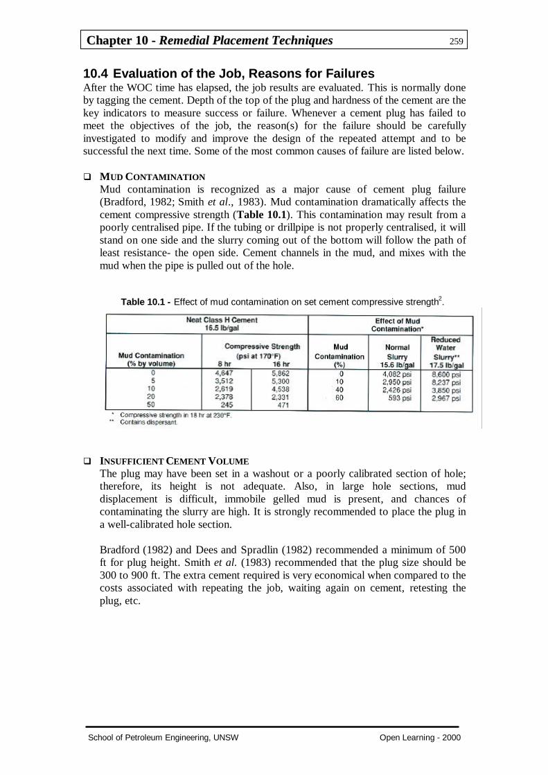
q MUD CONTAMINATIONMud contamination is recognized as a major cause of cement plug failure(Bradford, 1982; Smith et al., 1983). Mud contamination dramatically affects thecement compressive strength (Table 10.1). This contamination may result from apoorly centralised pipe. If the tubing or drillpipe is not properly centralised, it willstand on one side and the slurry coming out of the bottom will follow the path ofleast resistance- the open side. Cement channels in the mud, and mixes with themud when the pipe is pulled out of the hole.
Table 10.1 - Effect of mud contamination on set cement compressive strength2.
q INSUFFICIENT CEMENT VOLUMEThe plug may have been set in a washout or a poorly calibrated section of hole;therefore, its height is not adequate. Also, in large hole sections, muddisplacement is difficult, immobile gelled mud is present, and chances ofcontaminating the slurry are high. It is strongly recommended to place the plug ina well-calibrated hole section.
Bradford (1982) and Dees and Spradlin (1982) recommended a minimum of 500ft for plug height. Smith et al. (1983) recommended that the plug size should be300 to 900 ft. The extra cement required is very economical when compared to thecosts associated with repeating the job, waiting again on cement, retesting theplug, etc.

CChhaapptteerr 1100 -- RReemmeeddiiaall PPllaacceemmeenntt TTeecchhnniiqquueess 260
School of Petroleum Engineering, UNSW Open Learning - 2000
q PLUG SLIPPED DOWNHOLESmith et al. (1983) recognized that a heavy cement resting on top of a lightweightmud forms an unstable interface; as a result, the cement channels downward andbecomes diluted in the mud (in Fig. 10.23). The common practice of using anopen-ended drillpipe is a major contributor to plug failure, as the cement turningthe shoe causes considerable disturbances to the interface. This problem can beremedied by the placement of a viscous mud pill with a diverter tool. As analternative, a delayed-gel fluid could be used instead of the bentonite pill.
Fig. 10.23 - The unstable interface2.
Bour et al. (1986) recommended the placement of a reactive fluids system (RFS),which creates a rapid forming gel acting as a bridge upon which the cement slurrycan rest. As a slurry, they recommended the use of an adequate gel strengthcement (thixotropic) to counteract the density differential driving forces.
CChhaapptteerr 1100 -- RReemmeeddiiaall PPllaacceemmeenntt TTeecchhnniiqquueess 261
School of Petroleum Engineering, UNSW Open Learning - 2000
REFERENCES
1. “Cementing Technology” by Dowell Schlumberger. Published by Nova CommunicationsLtd, London, England (1984).
2. “Well Cementing” edited by E.B. Nelson. Published by Elservier (1990).
3. American Petroleum Institute, Specifications for Materials and Testing for Well Cements,API Spec 10, third edition, API, Dallas (1986).
4. Bour, D.L., Sutton, D.L., and Creel, P.G.: ”Development of Effective Methods for PlacingCompetent Cement Plugs”, paper SPE 15008, 1986.
5. Bradford, B.B.: “Setting Cement Plugs Requires Careful Planning and Execution forSuccessful Cementing Job”, Oil & Gas J. (Dec. 13, 1982) 102-104.
6. Dees, J.M. and Spradlin, W.N. Jr.: “Successful Deep Open-Hole Cement Plugs for theAnardako Basin”, paper SPE 10957, 1982.
7. Smith, R.C., Beirute, R.M., and Holman, G.B.: “Improved Methods of Setting SuccessfulWhipstock Cement Plugs”, paper SPE 11415, 1983.

CChhaapptteerr 1100 -- RReemmeeddiiaall PPllaacceemmeenntt TTeecchhnniiqquueess 262
School of Petroleum Engineering, UNSW Open Learning - 2000
REVIEW QUESTIONS
1. List six reasons of why or when squeeze cementing is necessary.
2. Describe low-pressure squeezing technique.
3. Shown below is typical hesitation-squeeze pressure behaviour, what do A, B, C and D (asindicated on the plot) indicate?
4. Describe the basic procedures of packer-squeeze technique.
5. With the help of the figure shown below, explain the bradenhead squeeze technique.
6. List five reasons for setting cement plugs.

CChhaapptteerr 1100 -- RReemmeeddiiaall PPllaacceemmeenntt TTeecchhnniiqquueess 263
School of Petroleum Engineering, UNSW Open Learning - 2000
7. What are advantages and disadvantages of dump bailer method of setting plug?
8. In designing cement plugs, what are the key factors that need to be considered?
9. What are the most common causes of failure in plug setting operations? How to them?