10,000/5,000 lumen portable led work light - paladin paladin instr manual.pdf · the paladin™...
TRANSCRIPT
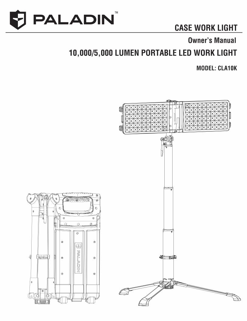
10,000/5,000 LUMEN PORTABLE LED WORK LIGHT
MODEL: CLA10K
CASE WORK LIGHTOwner’s Manual
™
CONTENTS
Introduction........................................................................................................3
Cautions/Warnings...............................................................................................4
Case Light Item Numbers.......................................................................................5
Tripod Assembly..................................................................................................6
Powering the Case Worklight...................................................................................8
Securing & Storing...............................................................................................11
Battery Run Time & Charging...................................................................................13
Specifications.....................................................................................................16
Dimensions........................................................................................................17
Spare Parts & Maintenance.....................................................................................18
Warranty & Contact Information................................................................................20
2
The Paladin™ Case Work Light is a portable 10,000 or 5,000 lumen, versatile work light. It can be powered by rechargeable lithium-ion batteries, 12/24 VDC car/truck power, or 120 VAC power.
Features:
• Ultra High Light Output – 10,000 Lumens
• Compact and Portable – Collapsible for storage, self contained
• Quick Deployment – Sets up in under 20 seconds
• Durable all-weather, injection molded with aircraft aluminum body construction
• Weatherproof toggle 3-position pushbutton switch – 10,000 Lumens/ 5,000 Lumens/ OFF
• 3 Power Options – 120VAC Cable/ 12/24 VDC Cable/ One or Two 36V Lithium-Ion Battery Packs
• High Efficiency -- Uses energy saving PWM technology; a 50% savings over ordinary transformer supplies
• Protected -- LED drivers with Overload protection, over-voltage protection, over-current protection, and bridge protection to secure LED driver and LED safety • Low Heat – No Ultraviolet (UV) radiation; no glare
• Long Battery life – Dual battery module provides power for Case Work Light to operate 6 to 7 hours at 10,000 lumens, or 12 to 14 hours at 5,000 lumens without a 120VAC source
• Mercury Free – Does not contain harmful mercury pollution; green environmental protection
INTRODUCTION
3
WARNING
CAUTION
NOTE
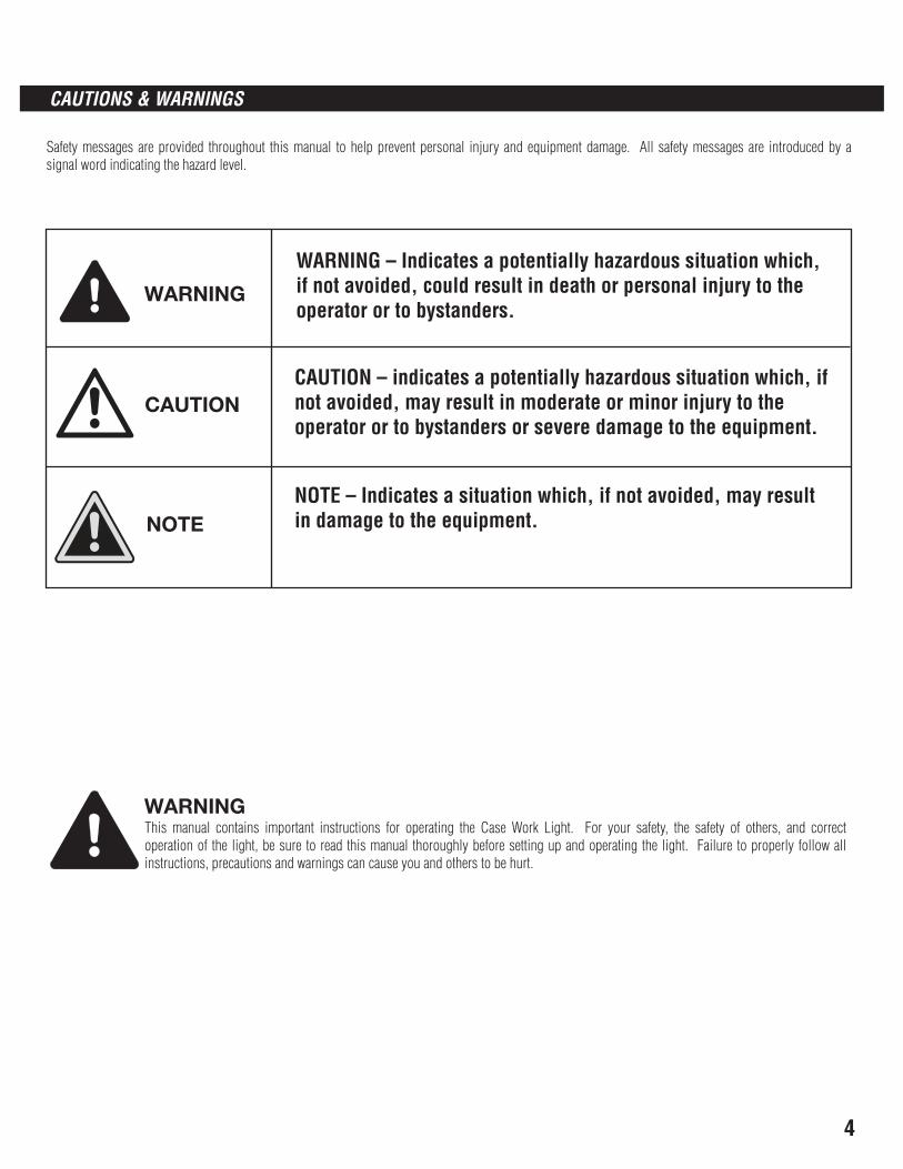
WARNING This manual contains important instructions for operating the Case Work Light. For your safety, the safety of others, and correct operation of the light, be sure to read this manual thoroughly before setting up and operating the light. Failure to properly follow all instructions, precautions and warnings can cause you and others to be hurt.
Safety messages are provided throughout this manual to help prevent personal injury and equipment damage. All safety messages are introduced by a signal word indicating the hazard level.
CAUTIONS & WARNINGS
WARNING – Indicates a potentially hazardous situation which, if not avoided, could result in death or personal injury to the operator or to bystanders.
CAUTION – indicates a potentially hazardous situation which, if not avoided, may result in moderate or minor injury to the operator or to bystanders or severe damage to the equipment.
NOTE – Indicates a situation which, if not avoided, may result in damage to the equipment.
4
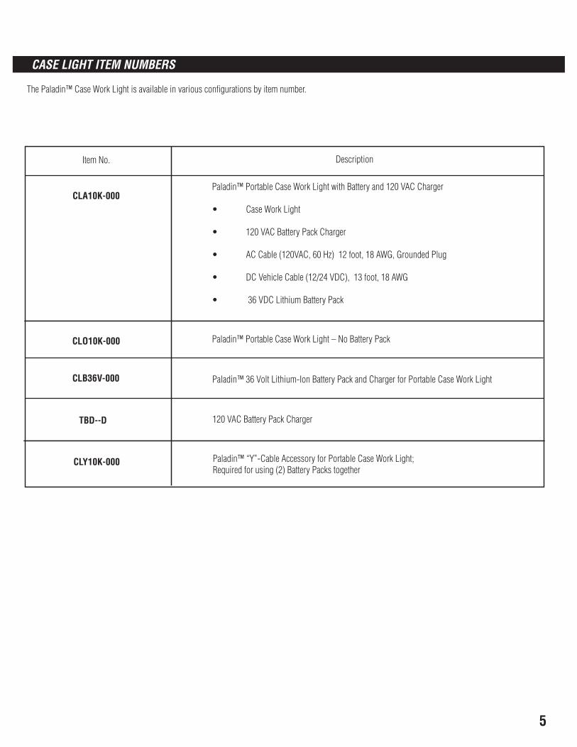
The Paladin™ Case Work Light is available in various configurations by item number.
Item No. Description
Paladin™ Portable Case Work Light with Battery and 120 VAC Charger
• Case Work Light
• 120 VAC Battery Pack Charger
• AC Cable (120VAC, 60 Hz) 12 foot, 18 AWG, Grounded Plug
• DC Vehicle Cable (12/24 VDC), 13 foot, 18 AWG
• 36 VDC Lithium Battery Pack
CLA10K-000
CLO10K-000 Paladin™ Portable Case Work Light – No Battery Pack
CLB36V-000 Paladin™ 36 Volt Lithium-Ion Battery Pack and Charger for Portable Case Work Light
TBD--D 120 VAC Battery Pack Charger
CLY10K-000 Paladin™ “Y”-Cable Accessory for Portable Case Work Light; Required for using (2) Battery Packs together
CASE LIGHT ITEM NUMBERS
5
6
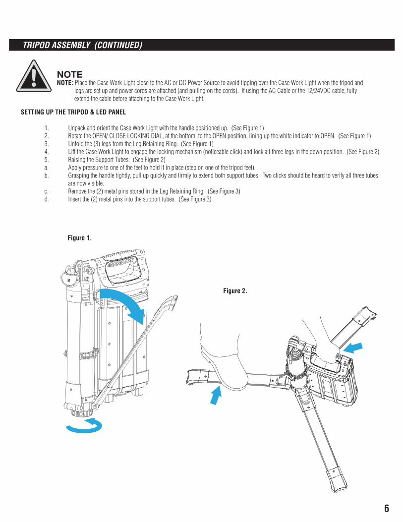
NOTE NOTE: Place the Case Work Light close to the AC or DC Power Source to avoid tipping over the Case Work Light when the tripod and legs are set up and power cords are attached (and pulling on the cords). If using the AC Cable or the 12/24VDC cable, fully extend the cable before attaching to the Case Work Light.
SETTING UP THE TRIPOD & LED PANEL
1. Unpack and orient the Case Work Light with the handle positioned up. (See Figure 1) 2. Rotate the OPEN/ CLOSE LOCKING DIAL, at the bottom, to the OPEN position, lining up the white indicator to OPEN. (See Figure 1) 3. Unfold the (3) legs from the Leg Retaining Ring. (See Figure 1) 4. Lift the Case Work Light to engage the locking mechanism (noticeable click) and lock all three legs in the down position. (See Figure 2) 5. Raising the Support Tubes: (See Figure 2) a. Apply pressure to one of the feet to hold it in place (step on one of the tripod feet). b. Grasping the handle tightly, pull up quickly and firmly to extend both support tubes. Two clicks should be heard to verify all three tubes are now visible. c. Remove the (2) metal pins stored in the Leg Retaining Ring. (See Figure 3) d. Insert the (2) metal pins into the support tubes. (See Figure 3)
Figure 1.
Figure 2.
TRIPOD ASSEMBLY (CONTINUED)
7
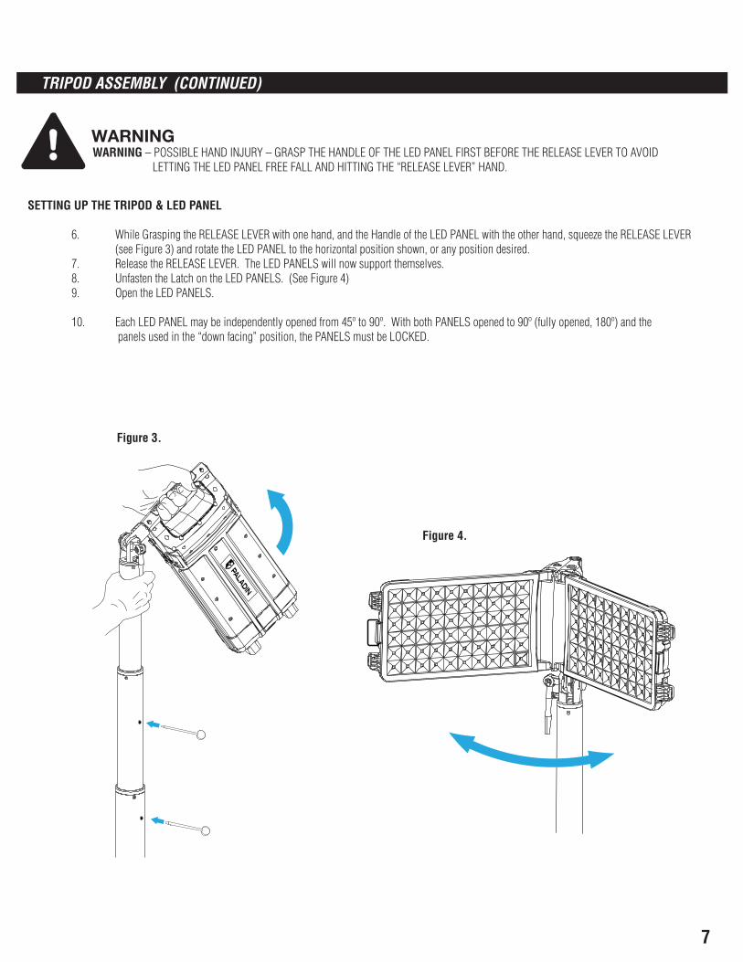
WARNING WARNING – POSSIBLE HAND INJURY – GRASP THE HANDLE OF THE LED PANEL FIRST BEFORE THE RELEASE LEVER TO AVOID LETTING THE LED PANEL FREE FALL AND HITTING THE “RELEASE LEVER” HAND.
SETTING UP THE TRIPOD & LED PANEL
6. While Grasping the RELEASE LEVER with one hand, and the Handle of the LED PANEL with the other hand, squeeze the RELEASE LEVER (see Figure 3) and rotate the LED PANEL to the horizontal position shown, or any position desired. 7. Release the RELEASE LEVER. The LED PANELS will now support themselves. 8. Unfasten the Latch on the LED PANELS. (See Figure 4) 9. Open the LED PANELS.
10. Each LED PANEL may be independently opened from 45º to 90º. With both PANELS opened to 90º (fully opened, 180º) and the panels used in the “down facing” position, the PANELS must be LOCKED.
Figure 3.
Figure 4.
TRIPOD ASSEMBLY (CONTINUED)
8
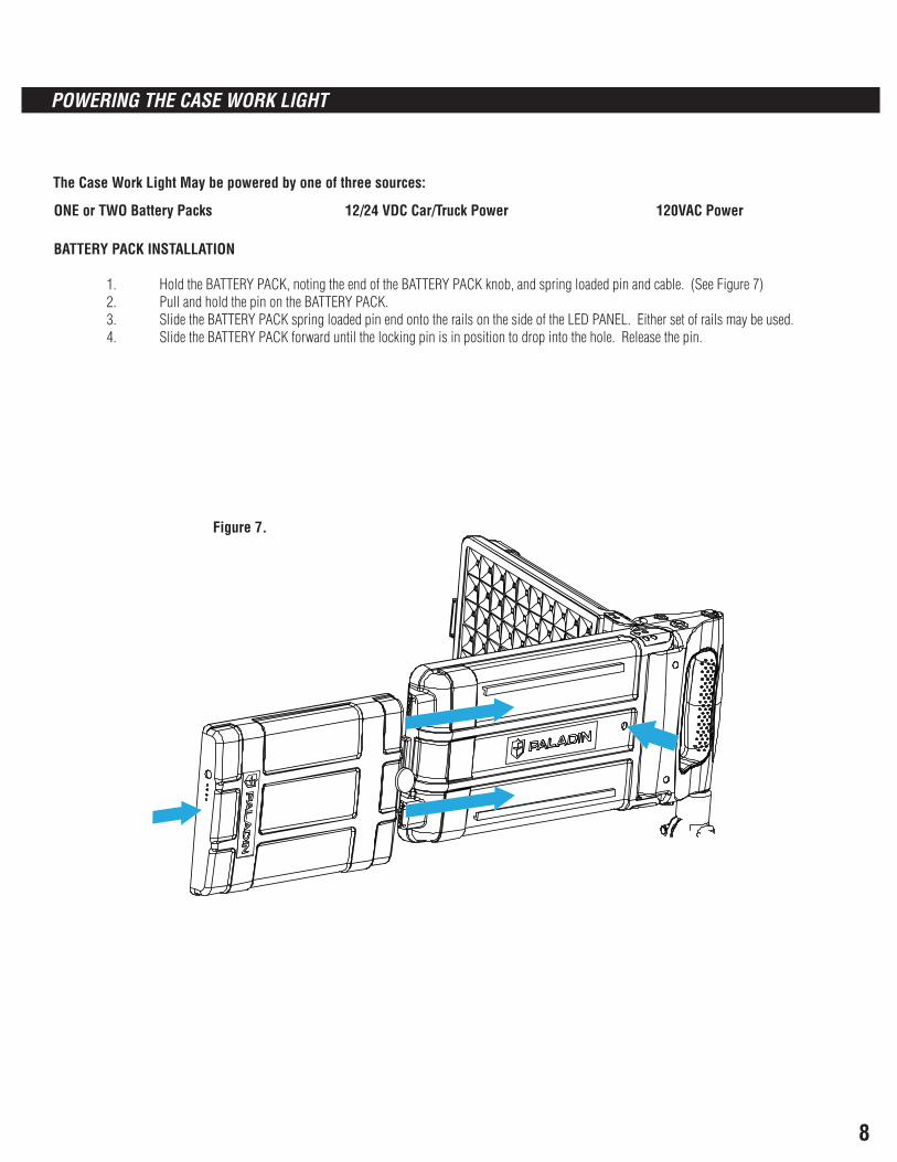
The Case Work Light May be powered by one of three sources:
ONE or TWO Battery Packs 12/24 VDC Car/Truck Power 120VAC Power
BATTERY PACK INSTALLATION
1. Hold the BATTERY PACK, noting the end of the BATTERY PACK knob, and spring loaded pin and cable. (See Figure 7) 2. Pull and hold the pin on the BATTERY PACK. 3. Slide the BATTERY PACK spring loaded pin end onto the rails on the side of the LED PANEL. Either set of rails may be used. 4. Slide the BATTERY PACK forward until the locking pin is in position to drop into the hole. Release the pin.
Figure 7.
POWERING THE CASE WORK LIGHT
9
ACDC
SETTING UP THE TRIPOD & LED PANEL
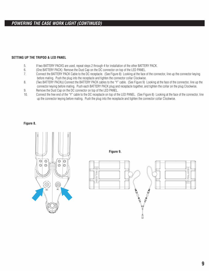
5. If two BATTERY PACKS are used, repeat steps 2 through 4 for installation of the other BATTERY PACK. 6. (One BATTERY PACK) Remove the Dust Cap on the DC connector on top of the LED PANEL. 7. Connect the BATTERY PACK Cable to the DC receptacle. (See Figure 8) Looking at the face of the connector, line up the connector keying before mating. Push the plug into the receptacle and tighten the connector collar Clockwise. 8. (Two BATTERY PACKs) Connect the BATTERY PACK cables to the “Y” cable. (See Figure 9) Looking at the face of the connector, line up the connector keying before mating. Push each BATTERY PACK plug and receptacle together, and tighten the collar on the plug Clockwise. 9. Remove the Dust Cap on the DC connector on top of the LED PANEL. 10. Connect the free end of the “Y” cable to the DC receptacle on top of the LED PANEL. (See Figure 8) Looking at the face of the connector, line up the connector keying before mating. Push the plug into the receptacle and tighten the connector collar Clockwise.
Figure 8.
Figure 9.
POWERING THE CASE WORK LIGHT (CONTINUED)
10
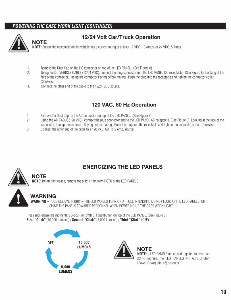
NOTE NOTE: Before first usage, remove the plastic film from BOTH of the LED PANELS.
NOTE NOTE: If LED PANELS are closed together to less than 22 ½ degrees, the LED PANELS will Auto Shutoff (Power Down) after (3) seconds.
NOTE NOTE: Ensure the receptacle on the vehicle has a current rating of at least 12 VDC, 10 Amps, or 24 VDC, 5 Amps.
12/24 Volt Car/Truck Operation
1. Remove the Dust Cap on the DC connector on top of the LED PANEL. (See Figure 8) 2. Using the DC VEHICLE CABLE (12/24 VDC), connect the plug connector into the LED PANEL DC receptacle. (See Figure 8) Looking at the face of the connector, line up the connector keying before mating. Push the plug into the receptacle and tighten the connector collar Clockwise. 3. Connect the other end of the cable to the 12/24 VDC source.
120 VAC, 60 Hz Operation
1. Remove the Dust Cap on the AC connector on top of the LED PANEL. (See Figure 8) 2. Using the AC CABLE (120 VAC), connect the plug connector end to the LED PANEL AC receptacle. (See Figure 8) Looking at the face of the connector, line up the connector keying before mating. Push the plug into the receptacle and tighten the connector collar Clockwise. 3. Connect the other end of the cable to a 120 VAC, 60 Hz, 2 Amp. source.
ENERGIZING THE LED PANELS
WARNING WARNING – POSSIBLE EYE INJURY – THE LED PANELS TURN ON AT FULL INTENSITY. DO NOT LOOK AT THE LED PANELS, OR SHINE THE PANELS TOWARDS PERSONNEL WHEN POWERING UP THE CASE WORK LIGHT.
Press and release the momentary 3-position SWITCH pushbutton on top of the LED PANEL. (See Figure 8) First “Click” (10,000 Lumens) / Second “Click” (5,000 Lumens) / Third “Click” (OFF) .
OFF 10,000LUMENS
5,000LUMENS
POWERING THE CASE WORK LIGHT (CONTINUED)
11
CAUTION
1. Press and release the momentary 3-position SWITCH pushbutton on top of the LED PANEL to OFF to power down Case Work Light. (See Figure 8) 2. Remove the external power Cable (AC Cable or DC Vehicle Cable) from its’ source. 3. Remove the appropriate power plug from the top of the LED PANEL -- AC receptacle or DC receptacle – by rotating the plug collar Counterclockwise. 4. If using a BATTERY PACK, disconnect the Battery Cable (or “Y” cable, if used) from the DC connector by rotating the plug collar Counterclockwise. If the “Y” cable was used, disconnect the “Y” cable from both BATTERY PACKS by unscrewing the connector collars Counterclockwise. 5. On top of the LED PANEL, reconnect attached Dust Caps to the appropriate AC or DC receptacles used. (See Figure 8) Secure the caps by seating the cap firmly on the connector.
NOTE NOTE: A BATTERY PACK WEIGHS OVER 5 POUNDS WHEN RELEASED! FIRMLY HOLD THE BATTERY PACK.
BATTERY PACK(s) may be stored with the Case Work Light, or removed
6. To remove BATTERY PACK(s): a. Grasp the BATTERY PACK with one hand. b. Locate the Pin on the BATTERY PACK. (See Figure 7) c. With the other hand, pull the Pin upward out of the hole to release the BATTERY PACK and slide it down the rails on the LED PANEL until the BATTERY Pack is free from the LED PANEL.
CAUTION: POSSIBLE LED PANEL DAMAGE – IF THE LED PANELS WERE LOCKED, THEY MUST BE UNLOCKED TO COLLAPSE, OR FOLD THE PANELS TOGETHER. SEE THE “LOCKING & UNLOCKING THE LED PANELS” SECTION OF THIS MANUAL
7. Close (fold together) the LED PANELS. 8. Latch the LED PANELS together using the LATCH on the end of the LED PANELS. (See Figure 4)
SECURING & STORING
12
WARNING WARNING – POSSIBLE HAND INJURY – GRASP THE HANDLE OF THE LED PANEL FIRST BEFORE THE RELEASE LEVER TO AVOID LETTING THE LED PANEL FREE FALL AND HITTING THE “RELEASE LEVER” HAND.
9. While grasping the RELEASE LEVER with one hand, and the handle of the LED PANEL with the other hand, squeeze the RELEASE LEVER and rotate the LED PANEL down to the vertical (storage) position. (See Figure 3) 10. Release the RELEASE LEVER. 11. Remove the (2) metal Pins inserted in the Tripod columns. (See Figure 3) 12. Store the (2) metal pins in the Leg Retaining Ring. (See Figure 3) 13. Grasp the handle of the LED PANEL and forcefully push down to collapse the (2) column supports. 14. Slightly raise the Case Work Light to release tension on the legs AND (see next step)
CAUTION CAUTION: IN THE NEXT STEP, ROTATING THE LOCKING DIAL WILL ALLOW THE (3) LEGS TO BE RELEASED AND THEY WILL FALL.
15. Rotate the OPEN/ CLOSE LOCKING DIAL, at the bottom, to the CLOSE position, lining up the white indicator to CLOSE. (See Figure 1) 16. Set the Case Work Light back down. 17. Fold the (3) legs up and secure them into the Leg Retaining Ring. (See Figure 1) 18. Rotate the OPEN/CLOSE LOCKING DIAL to the OPEN position.
SECURING & STORING (CONTINUED)
13
BATTERY RUN TIME & CHARGING
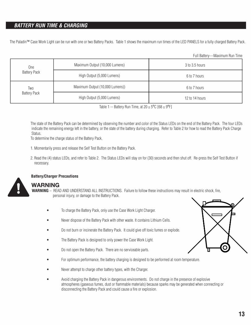
The Paladin™ Case Work Light can be run with one or two Battery Packs. Table 1 shows the maximum run times of the LED PANELS for a fully charged Battery Pack.
OneBattery Pack
TwoBattery Pack
Maximum Output (10,000 Lumens)
High Output (5,000 Lumens)
Maximum Output (10,000 Lumens))
High Output (5,000 Lumens)
Full Battery—Maximum Run Time
3 to 3.5 hours
6 to 7 hours
6 to 7 hours
12 to 14 hours
Table 1 -- Battery Run Time, at 20 ± 50C [68 ± 90F]
The state of the Battery Pack can be determined by observing the number and color of the Status LEDs on the end of the Battery Pack. The four LEDs indicate the remaining energy left in the battery, or the state of the battery during charging. Refer to Table 2 for how to read the Battery Pack Charge Status. To determine the charge status of the Battery Pack,
1. Momentarily press and release the Self Test Button on the Battery Pack. 2. Read the (4) status LEDs, and refer to Table 2. The Status LEDs will stay on for (30) seconds and then shut off. Re-press the Self Test Button if necessary.
WARNING WARNING – READ AND UNDERSTAND ALL INSTRUCTIONS. Failure to follow these instructions may result in electric shock, fire, personal injury, or damage to the Battery Pack.
• To charge the Battery Pack, only use the Case Work Light Charger.
• Never dispose of the Battery Pack with other waste. It contains Lithium Cells.
• Do not burn or incinerate the Battery Pack. It could give off toxic fumes or explode.
• The Battery Pack is designed to only power the Case Work Light.
• Do not open the Battery Pack. There are no serviceable parts.
• For optimum performance, the battery charging is designed to be performed at room temperature.
• Never attempt to charge other battery types, with the Charger.
• Avoid charging the Battery Pack in dangerous environments. Do not charge in the presence of explosive atmospheres (gaseous fumes, dust or flammable materials) because sparks may be generated when connecting or disconnecting the Battery Pack and could cause a fire or explosion.
Battery/Charger Precautions
14
BATTERY RUN TIME & CHARGING (CONTINUED)
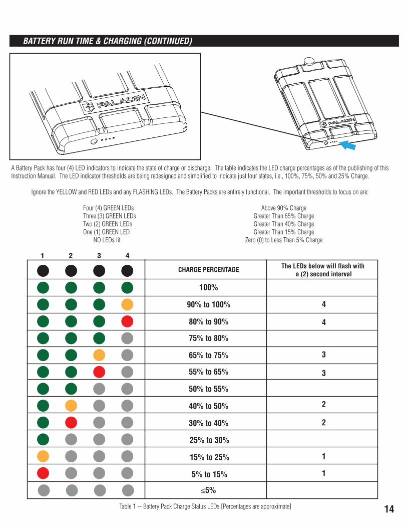
Table 1 -- Battery Pack Charge Status LEDs [Percentages are approximate]
CHARGE PERCENTAGE The LEDs below will flash with a (2) second interval
1 2 3 4
100%
90% to 100%
80% to 90%
75% to 80%
65% to 75%
55% to 65%
50% to 55%
40% to 50%
30% to 40%
25% to 30%
15% to 25%
5% to 15%
≤5%
4
4
3
3
2
2
1
1
A Battery Pack has four (4) LED indicators to indicate the state of charge or discharge. The table indicates the LED charge percentages as of the publishing of this Instruction Manual. The LED indicator thresholds are being redesigned and simplified to indicate just four states, i.e., 100%, 75%, 50% and 25% Charge.
Ignore the YELLOW and RED LEDs and any FLASHING LEDs. The Battery Packs are entirely functional. The important thresholds to focus on are:
Four (4) GREEN LEDs Above 90% Charge Three (3) GREEN LEDs Greater Than 65% Charge Two (2) GREEN LEDs Greater Than 40% Charge One (1) GREEN LED Greater Than 15% Charge NO LEDs lit Zero (0) to Less Than 5% Charge
15
BATTERY RUN TIME & CHARGING (CONTINUED)
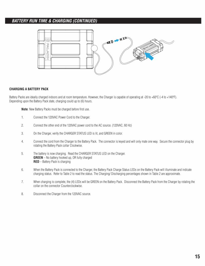
CHARGING A BATTERY PACK
Battery Packs are ideally charged indoors and at room temperature. However, the Charger is capable of operating at -20 to +60ºC (-4 to +140ºF).Depending upon the Battery Pack state, charging could up to (6) hours. Note: New Battery Packs must be charged before first use.
1. Connect the 120VAC Power Cord to the Charger.
2. Connect the other end of the 120VAC power cord to the AC source. (120VAC, 60 Hz)
3. On the Charger, verify the CHARGER STATUS LED is lit, and GREEN in color.
4. Connect the cord from the Charger to the Battery Pack. The connector is keyed and will only mate one way. Secure the connector plug by rotating the Battery Pack collar Clockwise.
5. The battery is now charging. Read the CHARGER STATUS LED on the Charger. GREEN – No battery hooked up, OR fully charged RED – Battery Pack is charging
6. When the Battery Pack is connected to the Charger, the Battery Pack Charge Status LEDs on the Battery Pack will illuminate and indicate charging status. Refer to Table 2 to read the status. The Charging/ Discharging percentages shown in Table 2 are approximate.
7. When charging is complete, the (4) LEDs will be GREEN on the Battery Pack. Disconnect the Battery Pack from the Charger by rotating the collar on the connector Counterclockwise.
8. Disconnect the Charger from the 120VAC source.
16
SPECIFICATIONS
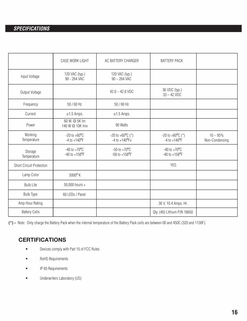
CASE WORK LIGHT AC BATTERY CHARGER BATTERY PACK
Input Voltage 120 VAC (typ.)90 - 264 VAC
120 VAC (typ.)90 – 264 VAC
Output Voltage 42.0 – 42.8 VDC 36 VDC (typ.)33 – 42 VDC
Frequency 50 / 60 Hz 50 / 60 Hz
Current ≤1.5 Amps.
60 W. @ 5K lm140 W @ 10K lmv 90 Watts
≤1.5 Amps.
Power
WorkingTemperature
-20 to +600C-4 to +1400F
-20 to +600C (*)-4 to +1400Fv
-20 to +600C (*)-4 to +1400F
10 – 95% Non-Condensing
StorageTemperature
-40 to +700C-40 to +1580F
-50 to +700C-58 to +1580F
-40 to +700C-40 to +1580F
Short Circuit Protection YES
Lamp Color 50000 K
Bulb Life 50,000 hours +
Bulb Type 60 LEDs / Panel
Amp Hour Rating 36 V, 10.4 Amps. Hr.
Battery Cells Qty. (40) Lithium P/N 18650
(*) = Note: Only charge the Battery Pack when the internal temperature of the Battery Pack cells are between 00 and 450C (320 and 1130F).
CERTIFICATIONS
• Devices comply with Part 15 of FCC Rules
• RoHS Requirements
• IP 65 Requirements
• Underwriters Laboratory (US)
17
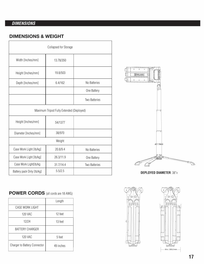
Collapsed for Storage
Width [Inches/mm] 13.78/350
Height [Inches/mm]
Depth [Inches/mm] 6.4/162 No Batteries
Two Batteries
One Battery
Maximum Tripod Fully Extended (Deployed)
Height [Inches/mm]
Diameter [Inches/mm]
Weight
Case Work Light [lb/kg] 20.8/9.4
Case Work Light [lb/kg] 26.3/11.9
Case Work Light[lb/kg
Battery pack Only [lb/kg]
19.8/503
54/1377
38/970
31.7/14.4
5.5/2.5
No Batteries
Two Batteries
One Battery
CASE WORK LIGHT
Length
12/24 13 feet
BATTERY CHARGER
120 VAC
Charger to Battery Connector
5 feet
49 inches
120 VAC 12 feet
8 in. / 203.2 mm
DIMENSIONS
DIMENSIONS & WEIGHT
DEPLOYED DIAMETER: 38”v
POWER CORDS (all cords are 18 AWG)
18
SPARE PARTS & MAINTENANCE
1. Pair of Metal Support Pins
2. Cotter Pins for Release Lever
3. Charger -- AC 120VAC Power Cord
4. Case Work Light -- AC 120VAC Power Cord
5. Case Work Light -- 12/24 VDC Cord
6. Battery Charger
7. “Y”- Cable
8. Leg Assembly: Replacement Tripod Legs – Consisting of Collar and (3) Legs
9. Leg Clip Ring
10. Head Assembly, including neck and top pole
11. Dust Covers (AC & DC electrical socket caps)
12. Latch Handle
13. Foot Pads
14. Handle e-Clips
19
SPARE PARTS & MAINTENANCE (CONTINUED)
Maintenance
1. Cleaning the LED PANEL Lenses a. DO NOT use any cleaning solvent to clean the lenses. b. DO NOT use any abrasive cleaner. c. Use a damp cloth to clean the LED PANELS , and tripod.
2. Periodic Inspection
20
You should read all of the instructions before attempting to use this product.
3 Year Limited Warranty
International Development Corporation (IDC) warrants this product against defects in material or workmanship for a period of three (3) years from the date of original purchase. IDC agrees to either repair the product or replace it, at the sole discretion of IDC. Only the original purchaser of this product is extended this warranty. No warranty work will be provided under this warranty without purchaser's receipt or other proof of the date of original purchase acceptable to IDC. Proof of the date of purchase must be provided to IDC if the product is returned. Purchasing this product from a third party vendor negates all warranties
(expressed or implied) in this warranty.
The warranty does not apply to the following terms/conditions: 1.) acts of God, 2.) products that have been subjected to unauthorized repair, opened, disassembled, and/or otherwise modified, 3.) products used not in accordance with directions, 4.) damages exceeding the total cost of product, 5.) sealed lamps and/or lamp bulbs, LEDs, and batteries, 6.) the finish of any portion of the product (i.e. surface scratches, weathering, corrosion, discoloration of
brass components, as this is considered normal wear and tear), 7.) damages caused by shipping, improper handling, accident, misuse or abuse. IDC is not responsible for damage of merchandise in transit. Repaired or replaced products shall be subject to the terms of this warranty and are inspected prior to return
shipment. Damages that are incurred during transit should be reported at once to the carrier and a claim should be filed with them.
IDC SHALL NOT BE LIABLE FOR INCIDENTAL, SPECIAL OR CONSEQUENTIAL DAMAGES RESULTING FROM THE USE OF THE PRODUCT OR ARISING OUT OF ANY BREACH OF THIS WARRANTY. ALL IMPLIED WARRANTIES, IF ANY, INCLUDING IMPLIED WARRANTIES OF MERCHANTABILITY AND FITNESS FOR A PARTICULAR PURPOSE, ARE LIMITED IN DURATION TO THE DURATION OF THIS EXPRESS
WARRANTY. Some states do not allow the exclusion or limitation of incidental or consequential damages, or limitations on how long an implied warranty lasts, so the above exclusions or limitations may not apply to you. No other warranty, written or verbal, will be honored for this product. This warranty grants you
specific legal rights, you may also have other rights which vary from state to state. There are no other warranties except those stated above.
Thank YouWe appreciate your purchase of this Paladin™ product. Paladin™ has made every effort to supply a quality product that insures long, trouble-free service. In
the event that you have any type of problems with this product and require a return address or for any other assistance please call our Toll Free Number 1-888-394-6765 • 8:00 A.M. - 5:00 P.M. Central Time, Monday - Friday • Email us at: [email protected]
You will need the following information: Model/Item Number of Product, Receipt, and Date of Purchase
All drawings and text are © copyright of Paladin™, a division of International Development Corp. • Printed in China
This product is manufactured by Paladin™, a division of International Development Corp.899 Henrietta Creek Rd. Roanoke, TX 76262 USA
Toll-free: 888-394-6765