101.141 lt-racer with propeller drive - opitecnbg-web01.opitec.com/img/101/141/101141be.pdf ·...
TRANSCRIPT

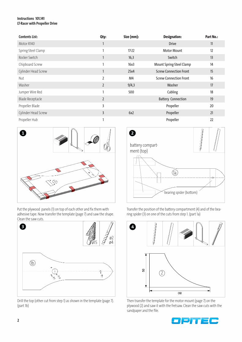
101.141
LT-Racer with Propeller Drive
Contents List: Qty: Size (mm): Designation: Part No.:
Plywood 2 250x100x3 Base and Cover Plate 1
Plywood 1 80x50x10 Motor Mount 2
Wooden Strip 1 150x15x10 Bearing Spider 3
Wooden Strip 1 150x25x10 Battery Compartment 4
Plywood 1 60x45x6 Intermediate Piece 5
Impeller 4 ø37 Wheels 6
Spacers 4 ø5 Spacer for Wheels 7
Eye Bolt 4 12 Shaft Spider 8
Metal Axis 1 120x3 Rear Axle 9
Metal Axis 1 70x3 Front Axle 10
Required Tools:
FretsawWood Glue, Drill Side Cutter,
Locking Clamp Slot Screwdriver
Ruler PencilSandpaper Round File
Phillips Screwdri-ver
Engineer´s File
Soldering Iron
ø 2ø 4ø 8
Step Dril
ø 15
Adhesive Tape
Please NoteThe OPITEC range of projects is not intended as play toys for young child-
ren.They are teaching aids for young people learning the skills of Craft, Design and Technology.These projects should only be undertaken and te-
sted with the guidance of a fully qualified adult.The finished projects are not suitable to give to children under 3 years
old. Some parts can be swallowed. Danger of suffocation!
2
2
3 4
1b
1a
1
Instructions 101.141LT-Racer with Propeller Drive
Transfer the position of the battery compartment (4) and of the bea-ring spider (3) on one of the cuts from step 1. (part 1a)
Contents List: Qty: Size (mm): Designation: Part No.:
Motor R140 1 Drive 11
Spring-Steel Clamp 1 17-22 Motor Mount 12
Rocker Switch 1 16,3 Switch 13
Chipboard Screw 1 16x3 Mount Spring-Steel Clamp 14
Cylinder Head Screw 1 25x4 Screw Connection Front 15
Nut 2 M4 Screw Connection Front 16
Washer 2 9/4,3 Washer 17
Jumper Wire Red 1 500 Cabling 18
Blade Receptacle 2 Battery Connection 19
Propeller Blade 3 Propeller 20
Cylinder Head Screw 3 6x2 Propeller 21
Propeller Hub 1 Propeller 22
battery compart-ment (top)
bearing spider (bottom)
Drill the top (other cut from step 1) as shown in the template (page 7). (part 1b)
ø2ø4
Then transfer the template for the motor mount (page 7) on the plywood (2) and saw it with the fretsaw. Clean the saw cuts with the sandpaper and the file.
2
Put the plywood panels (1) on top of each other and fix them with adhesive tape. Now transfer the template (page 7) and saw the shape. Clean the saw cuts.
ø15

3
6
7
5
4
4a 4a4b
ø4
9 10
8
Glue the wooden strips from step 6 on top of 1a. Glue the motor mount (2) centrical and flush with the rear edge on the upper part of 1b.
Glue the intermediate piece (5) on the front part of 1a.
4a
4a
4b
ø8
1a1b
1a
Cut the wooden strip (4) according to the instructions and clen the saw cuts.
Cut the wooden strip (3) according to the instructions and clen the saw cuts. Take the 45mm long piece and drill a 4mm big hole in it as shown. Moreover drill a 5mm deep blind hole in it. Use the ø 8mm drill.
3b
Transfer the template for the intermediate piece (5) (page 9)on the plywood (5) and saw it with the fretsaw. Clean the saw cuts with the sandpaper and the file.
5
Instructions 101.141LT-Racer with Propeller Drive
5
3a

3
12
13
Put the manufactured motor into the clamp.
Instructions 101.141LT-Racer with Propeller Drive
12
14
14
13
19
11
Insert the switch (13) in the anticipated eyelet of ø 15mm.
15
Crosscut three cable pieces (2x 150mm, 1x 200mm) from the jumper wire (18) and remove insulation on both sides. Attach one cable (150mm) to the positive terminal of the motor (marked with point), take it through the drill in the upper part and connect it to the external switch port. Connect the second end with the middle switch connector and connect the other end with a blade receptacle (19). Connect the 200mm cable to the negative terminal of the motor, take it through the drill and connect the end with a blade receptacle (19). Solder the connections.
200mm
150mm
150mm
Fix the propeller blades (20) with the cylinder head screws (21) on the propeller hub (22) as shown. Afterwards put the rotor on the motor drive (11).
20
2221
11
Put the spring steel clamp (12) centrical on the motor mount (2) as shown and fix it with the chipboard screw (14).

Instructions 101.141LT-Racer with Propeller Drive
16 17
ø4
18
Install the front axle support (3a) with the cylinder head screw (15) and one washer (17) as shown. Fix it with two nuts (16) and one washer from above.
19
Glue the rear axle support (3b) flush with the rear edge on the bottom side. Let the glue dry well.
21
10
Insert the metal axis (10) as shown and clip on spacers (7) on each side. Then fix the impellers (6).
6
7
20
Transfer and mark the position oft he eye bolts (8) on the axle suppor-ters according to the instructions. Screw the eye bolts in and look to it that the eye bolts of each axle are exactly mirrored.
Glue the top on the intermediate piece (5) and the wooden strips (4a - 4c) as shown. Fix it with locking clamps until the glue is dry.
3a15
1716
3b
Now drill the intermediate piece and the base with a 4mm drill use the drill in the upper part.
6 7
8

22
Instructions 101.141LT-Racer with Propeller Drive
Insert battery and get on the road!Insert the metal axis (9) as shown and clip on spacers (7) on each side. Then fix the impellers (6).
96
6
7
7

Instructions 101.141LT-Racer with Propeller Drive
Front Position
Rear Axle Position
Batte
ry Co
mpa
rtmen
t
Batte
ry Co
mpa
rtmen
t
Battery Compartment
Connecting Piece
Motor Bracket