101220031 manual instruccions m21 rev 3 en angles · 2 thank you for choosing a product from...
TRANSCRIPT

R-MI-M21 Rev.: 3 English version
Series M21 Variable area flowmeter
Instructions manual
The art of measuring

2
Thank you for choosing a product from Tecfluid S.A.
This instruction manual allows the installation, configuration, programming and maintenance. It is recommended to read it before using the equipment.
This document shall not be copied or disclosed in whole or in any part by any means, without the written permission of Tecfluid S.A.
Tecfluid S.A. reserve the right to make changes as deemed necessary at any time and without notice, in order to improve the quality and safety, with no obligation to update this manual.
Make sure this manual goes to the end user.
Keep this manual in a place where you can find it when you need it.
In case of loss, ask for a new manual or download it directly from our website www.tecfluid.com Downloads section.
Any deviation from the procedures described in this instruction manual, may cause user safety risks, damage of the unit or cause errors in the equipment performance.
Do not modify the equipment without permission. Tecfluid S.A. are not responsible for any problems caused by a change not allowed. If you need to modify the equipment for any reason,
PREFACE
WARNINGS

3
TABLE OF CONTENTS
SERIES M21
1 INTRODUCTION ........................................................................... 6
2 WORKING PRINCIPLE ................................................................... 6
3 RECEPTION .................................................................................. 8
4 INSTALLATION ............................................................................. 8
4.1 Valves ................................................................................ 8
4.2 Filters ................................................................................. 8
4.3 Straight pipe sections ......................................................... 8
5 OPERATION ................................................................................. 9
5.1 Gas flow measurement ....................................................... 9
5.2 Gas damping mechanism .................................................... 10
5.3 Liquid flow measurement .................................................... 11
6 RCA / RCD FLOW REGULATORS .................................................. 12
6.1 Regulation curves ............................................................... 13
AMD LIMIT SWITCH
7 INTRODUCTION ........................................................................... 15
8 OPERATION ................................................................................. 15
9 MOUNTING THE LIMIT SWITCH IN AN EXISTING EQUIPMENT ....... 16
9.1 Kit contents ......................................................................... 16
9.2 Preparing the kit ................................................................. 16
9.3 Assembling the AMD kit ...................................................... 17
9.4 Switching point adjustment ................................................. 18
9.5 Electrical connection ........................................................... 19
9.6 Mounting ........................................................................... 19
10 ELECTRICAL CONNECTION .......................................................... 19
TH6 TRANSMITTERS
11 INTRODUCTION ........................................................................... 20
12 MODELS ...................................................................................... 20
12.1 TH6 ................................................................................... 20
4
12.2 TH6H ................................................................................. 20
13 ELECTRICAL CONNECTION .......................................................... 20
13.1 Power supply and analog output ......................................... 21
14 4-WIRE CONNECTION .................................................................. 21
15 HART TRANSMITTERS ................................................................. 22
15.1 Additional functions with HART communication .................... 22
15.2 HART communication characteristics ................................... 22
16 ”WRITE PROTECT” ....................................................................... 23
17 MAINTENANCE ............................................................................ 24
17.1 Series M21 ........................................................................ 24
17.2 M21 with damping system .................................................. 25
17.3 Potential problems with the metering tube ............................ 25
17.3.1 Jammed float .......................................................... 25
17.3.2 Lack of magnetic field ............................................. 26
17.3.3 Damaged calibrated orifice and/or float .................... 26
17.4 Potential problems with the indicator housing ........................ 26
17.4.1 The indicator pointer rubs on the reading scale ......... 26
17.4.2 Deviation of the zero on the scale ............................ 26
17.5 RCA regulator maintenance ................................................. 27
17.6 RCD regulator maintenance ................................................ 28
17.7 AMD limit switch maintenance ............................................. 29
17.7.1 Electrical verification ................................................ 29
17.8 TH6 transmitter maintenance ............................................. 30
18 TECHNICAL CHARACTERISTICS ................................................... 30
18.1 Series M21 ......................................................................... 30
18.2 AMD limit switch ................................................................. 31
18.3 TH6 transmitter .................................................................. 31
18.3.1 Power supply .......................................................... 31
18.3.2 Outputs .................................................................. 31
18.3.3 General characteristics ............................................ 31

5
19 SAFETY INSTRUCTIONS ............................................................... 32
19.1 Pressure equipment directive .............................................. 32
19.2 Certificate of conformity TR CU (EAC marking) ..................... 32
20 ADDITIONAL INSTRUCTIONS FOR THE ATEX VERSION ................. 33
20.1 Non-metallic parts .............................................................. 33
20.2 Connecting conductive parts to earth .................................. 33
20.3 AMD limit switch ................................................................. . 34
20.4 TH6 transmitters ................................................................. 34
20.5 Marking .............................................................................. 35
21 FLOW RANGES ............................................................................ 36
22 DIMENSIONS ............................................................................... 37
23 ATEX CERTIFICATE ...................................................................... 40
24 DECLARATIONS OF CONFORMITY ACCORDING TO ATEX ............ 43
6
SERIES M21
1 INTRODUCTION The series M21 are flowmeters for liquids, gases and steam.
They are very robust instruments prepared to work under extreme conditions.
They have local flow rate indication by means of magnetic coupling, with scales calibrated in l/h, m3/h, kg/h, t/h, %, etc.
They can fit switches or electronic transmitters that allow to detect a specific flow rate and provide a flow rate signal to a remote device.
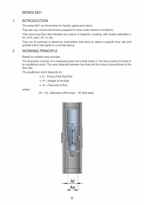
2 WORKING PRINCIPLE
Based on variable area principle.
The flowmeter consists of a measuring tube and a float inside it. The flow pushes the float to an equilibrium point. The area obtained between the float and the tube is proportional to the flow rate.
The equilibrium point depends on:
E = Force of the fluid flow
Ff = Weight of the float
Al = Free area of flow
where: (Al = Ao, calibrated orifice area, - Af, float area)

7
The M21-H... models have horizontal inlet and outlet, and optionally they can be supplied with a regulating valve on the inlet.
M21 models always work in a vertical position with upwards flow.
The equilibrium point is determined by considering the fluid force and the float weight.

8
3 RECEPTION
The series M21 flowmeters are supplied conveniently packaged for their protection during transportation and storage, together with their instructions manual for installation and operation.
The instruments are supplied tested in our calibration rigs, ready for installation and service.
Before installing the flowmeter, remove all the blocking elements.
With the instrument in its working position, move the float and check that the indicating needle moves all over the scale and returns to zero.
4 INSTALLATION
Flowmeters models M21 must be installed in a completely vertical position and with upwards flow direction.
It is important that the position is completely vertical given that deviations of about 5º can produce errors of about 8-10% of the readings.
4.1 Valves
If the fluid to be measured is a liquid, it is recommended to install a regulating valve before the flowmeter (see point 5.3), or to use a M21-H... model, which already includes a valve on the inlet.
For gas flow measurement, the valve position will depend on the calibrating pressure (see point 5.1).
Valves should always be opened slowly to avoid water hammers.
4.2 Filters
The installation of a filter before the instrument is important, this will avoid possible obstructions and breakdowns in the measuring system.
The filter mesh should be maximum 200 μm.
In case of having abundant magnetic particles in suspension, it is necessary to mount a magnetic filter on the inlet of the instrument to avoid the accumulation of particles around the float, which would make it to jam.
4.3 Straight pipe sections
In order to have stable readings, it is essential to avoid turbulences. To do this, it is necessary to install the instrument in a straight pipe section. This section should have the same inner diameter as the flowmeter. The required minimum distances upstream and downstream of the sensor are the following:
Upstream 5 DN Downstream 3 DN
These distances must be free of elements that can disturb the flow profile, such as elbows, diameter changes, valves, etc.

9
5 OPERATION
Once the meter is installed, the regulating valve should be opened slowly. The fluid flow will move the float which, by means of magnetic coupling, moves the indicating needle.
Any variations of working conditions with respect to those when calibrated can induce reading errors. The calibration working conditions are indicated on the instrument’s dataplate.
5.1 Gas flow measurement
The working pressure and temperature are of maximum importance for correct gas measurement as they directly affect the scale readings.
For example, if a meter is calibrated at 2 bar gauge and the working pressure is 1 bar gauge there will be an error of about 22%.
In the same way, if working temperature does not match calibrating temperature, errors will be induced in the flow rate readings.
In applications of gas flow measurement where the calibrating pressure of the instrument corresponds to the inlet pressure, being higher than the atmospheric pressure, the regulating valve must be installed downstream of the flowmeter. Thus, it is ensured that the instrument works at calibrating pressure and a back pressure that keeps the float in equilibrium is obtained.
NOTE: Scheme valid for gas flow measurement applications with a pressure higher than atmospheric. For gases at atmospheric pressure, turn valves upside down.
The flow should be adjusted by means of the regulating valve, while keeping the shut off valve fully open.
REGULATING VALVE
SHUT OFF VALVE

10
If the regulation is done using the shut off valve, in open circuits or at low gas flow in the meter, the gas will expand which will sharply diminish its density, providing very serious reading errors.
If the flow is regulated by the shut off valve, the float usually experiences an oscillating movement which produces a shut off action until sufficient pressure is gained to overcome its weight. The sudden fall of pressure, when the gas escapes, will make it fall. This cycle is repeated generating an oscillating measurement (resonance).
In applications where the gas outlet is at atmospheric pressure, install the regulating valve upstream of the flowmeter if the flowmeter was calibrated at atmospheric pressure. The shut off valve is then installed downstream of the flowmeter and it should be fully open.
The valve opening procedure should be as following:
- With the regulating valve closed, fully open the shut off valve.
- Gradually open the regulating valve until the desired flow rate.
And for closing:
- Close the regulating valve gradually until zero flow rate.
- Fully close the shut off valve to isolate the flowmeter.
Operating in a different way may involve water hammers that can damage the meter reading or generate instabilities.
REMARK: For gas applications at a pressure higher than the atmospheric pressure, it is recommended to use the M21 models without valve and install a separate valve at the outlet of the flowmeter.
M21-H... models do not allow their own valve to be mounted at the outlet, they are only available with valve at the inlet.
5.2 Gas damping mechanism
M21 ¼” damping mechanism M21 ½” and ¾” damping mechanism
BSP connection
BSP connection
NPT connection
NPT connection

11
When measuring low pressure gas flow with AISI 316L floats, oscillation of the float often occurs, which makes it very difficult to read the flow rates. In these cases it is recommended to install a damper in the instrument.
The damper consists of a piston mounted inside a cylinder, closed at its lower end. The compression forces of the gas absorb the floats oscillations, maintaining it stable in the reading point.
Close the valves during work stops at the end of the working day in order to avoid sudden surges when started up. If the float hits the stops sharply this could cause damage to the meter.
5.3 Liquid flow measurement
When measuring liquids the regulating valve should be installed as shown in the following figure.
Being the shut off valve partially open, open the regulating valve slowly until the needle of the indicator housing shows a low flow rate. Then also open the shut off valve slowly in order to get rid of the air and then progressively to fully opened.
The required flow rate is then regulated by using the regulating valve.
Close the valves during work stops at the end of the working day in order to avoid sudden surges when started up. If the float hits the stops sharply this could cause damage to the meter.
SHUT OFF VALVE
REGULATING VALVE

12
6 RCA / RCD FLOW REGULATORS
The M21 series flowmeters are built to incorporate the RCA and RCD regulators, that keep a constant flow rate when the operating pressure at the inlet or outlet are not constant.
In applications for gases, the RCA model is used in installations where inlet pressure is variable and outlet pressure or counter pressure is constant, while model RCD is used in installations where the inlet pressure is constant and outlet pressure or counter pressure is variable.
In liquids, model RCA is the commonly used.
RCA
P0
P2
RCD
P0
P2

13
The differential pressure between P0 and P2 should always be higher than 350-450 mbar depending on the model. This differential pressure is calculated for the proper operation of the flow rate regulator.
6.1 Regulation curves
The flow curves show the relationship between the inlet pressure P0 and the counter pressure P2 in the RCA regulator.
The different flow rates are adjusted by means of the regulating valve of the flowmeter. The counter pressure P2, in these cases, corresponds to the atmospheric pressure.
variation without regulator
variation with regulator
P0 = inlet pressure RCA regulator (low flow)
Q air (Nl/h)
P0 (bar)
The dotted line shows the variation of flow without the action of the constant flow regulator.
With constant flow regulator, variations of 100% in the inlet pressure P0 involve variations of flow of less than 1%.

14
variation of flow
P0 = inlet pressure RCA regulator (high flow)
Q air (Nl/h)
P0 (bar)
variation of flow
P0 = outlet pressure RCD regulator (low flow)
Q air (Nl/h)
P0 (bar)

15
AMD LIMIT SWITCH 7 INTRODUCTION
The AMD limit switch can be used to generate an alarm or an operation when the flow rate that the instrument is measuring reaches a preset value on the scale plate.
The AMD limit switch consists of a NAMUR slot type inductive sensor, that is actuated by a vane. Given that there is no physical contact in the operation, the limit switch has no influence on the indicator needle movement.
An instrument can be equipped with one or two sensors, depending on the number of points to be detected. A NAMUR amplifier with a relay output can be supplied as an option.
8 OPERATION
The indicator needle moves together with the vane mounted on its shaft. When the vane enters into the slot of the sensor, the limit switch changes its state.
The sensor is mounted on a support which includes a needle that indicates the switching position. The needle, that is below the scale plate, can be seen through the scale slot.
Switching points

16
9 MOUNTING THE LIMIT SWITCH IN AN EXISTING EQUIPMENT When the AMD limit switch is to be fitted to an existing device, please follow these steps.
9.1 Kit contents
The kit contains the following elements:
In the kits, the gaskets (5) and the blanking plugs (7) are not provided as loose parts. They are incorporated in the cable glands (6).
9.2 Preparing the kit
Remove the cover, unscrewing the four screws M4.
Slide the scale plate in the direction indicated in the figure, until it is released from the slot.
Ensure that the gaskets (5) are placed in the thread of the gland (6). If not, they should be placed. Remove the plugs from the indicator box with a flat screwdriver and replace them by the two cable glands.
The cable glands that are not expected to be used should be left with the blanking plug (7) placed to preserve watertight.
AMD kit
Quantity Material Position
1 AMD limit switch circuit 1
2 Self tapping screw DIN7982 B-2,2 x 9,5 Nº2 A2 2
1 AMD vane 3
1 Self tapping screw DIN7982 B-2,2 x 9,5 Nº2 A2 4
2 Gasket 5
2 Cable gland IP68 6
2 Cable gland blanking plug 7
Cable glands (6) Blanking plug (7)

17
9.3 Assembling the AMD kit
Slide the circuit (1) into the slot until it stops, and then screw it as shown in the figure.
Place the vane (3) in the position shown in the figure. The height on the shaft should be such that when the vane passes through the sensor slots, remains centered without touching them. Tighten the screw (4) holding the vane against the shaft.
Slot
Screw (2)
Screw (2)
Vane (3)

18
9.4 Switching point adjustment
At the bottom of the switching needle, the fixing nuts of the switching points can be found.
To move the switching point, the fixing nuts have to be slightly loosen without removing the scale plate (see figure on the next page). After that, place the switching point at the required scale value, and fix it with the nuts.
As standard, when the instrument has only one AMD, it is configured as a minimum limit switch.
Switching needles
Switching needles
Fixing nuts
Fixing nuts

19
9.5 Electrical connection
Do it according to section 10.
9.6 Mounting
Slide the scale plate into the slot until it stops as shown in the figure. Mount the cover with the four screws M4.
10 ELECTRICAL CONNECTION For the electrical connection, the instrument is provided with a four terminal connector.
For the electrical installation it is recommended to use multiple conductor cables with sections of 0.25 or 0.5 mm2, in order to make it easier to connect.
Before starting the installation, check that the cable glands are the right size for the cables to be used, this will guarantee the instrument will stay watertight. The M12x1.5 cable glands used are for cables with outside diameters between 2.5 mm and 6.5 mm.
Peel the outside insulation to free the inner cables. It is recommended to tin the ends of the wires to avoid loose ends. Pass the cables through the cable glands and screw down in the corresponding positions of the terminal strip. Once the wiring is finished make sure that the cables are well gripped by the cable glands to maintain the degree of protection.
The cable glands must be always closed. Entry of dust or some types of vapours can damage the internal system of bearings and therefore the equipment.
To gain access to the terminal block, the scale plate must be removed. To do this, slide it to the left through the slot until released.
The numeration of the terminals is the following:
Limit switch 2 (maximum)
Limit switch 1 (minimum)

20
TH6 TRANSMITTERS 11 INTRODUCTION
Transmitters TH6 are electronic position transducers with a microprocessor. The instrument uses the Hall effect to capture the field of a magnet. This signal, after the microcontroller processing, is converted into a current signal of 4-20 mA in a 2-wire loop. This signal is proportional to the flow rate.
12 MODELS
12.1 TH6
It is a 4 to 20 mA transmitter proportional to flow rate. 4 mA corresponds to beginning of the scale. 20 mA corresponds to full scale. Between the beginning of the scale and the first point of the scale the analog output is constant at 4 mA, to avoid false readings of flow rate.
12.2 TH6H
It is a TH6 transmitter that incorporates HART TM protocol compatibility. With this protocol the user can change the measuring range of the 4-20 mA loop, and data like flow rate, with its associated measuring units.
13 ELECTRICAL CONNECTION For the electrical connection, the transmitter has two screw terminals.
For the electrical installation it is recommended to use multiple conductor cables with individual cable sections in the order of 0.25 to 0.5 mm2 in order to make it easier to connect.
A twisted pair wiring should be used to avoid electrical interferences in the 4-20 mA loop. In some instances, shielded cable may be necessary.
Before starting the installation, check that the cable glands are the right size for the cables to be used, this will guarantee the instrument will stay watertight. The M12x1.5 cable glands used are for cables with outside diameters between 2.5 mm and 6.5 mm.
Peel the outside insulation to free the inner cables. It is recommended to tin the ends of the wires to avoid loose ends. Pass the cables through the cable glands and screw down in the corresponding positions of the terminal strip. Once the wiring is finished make sure that the cables are well gripped by the cable glands to maintain the degree of protection.
The cable glands must be always closed. Entry of dust or some types of vapours can damage the internal system of bearings and therefore the equipment.
To help in the wiring of the equipment, the description of the terminals is marked on the printed circuit next to the terminal strip.
Before connecting the power supply, you must be sure that the supply voltage is the correct for the installation. The power supply voltage is indicated on the label of the transmitter.

21
13.1 Power supply and analog output
The connection is made in the terminal block. The positive terminal of the power supply is connected to the position + and the positive terminal of the load in the position -. The negative terminals of the power supply and the load are connected together. The instrument works in a 2-wire system, that is, the supply and signal line are the same. It is recommended to use a twisted pair wiring or shielded cable to avoid interferences in the current loop.
14 4-WIRE CONNECTION
If Direct Current power supply for the transmitter is not available in the installation, it will be necessary to incorporate an additional power supply as in the following figure.
Power supply
12 to 36 VDC
Mains
22
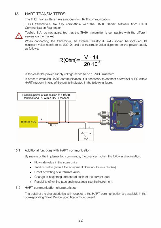
15 HART TRANSMITTERS The TH6H transmitters have a modem for HART communication.
TH6H transmitters are fully compatible with the HART Server software from HART Communication Foundation.
Tecfluid S.A. do not guarantee that the TH6H transmitter is compatible with the different servers on the market.
When connecting the transmitter, an external resistor (R ext.) should be included. Its minimum value needs to be 200 Ω, and the maximum value depends on the power supply as follows:
In this case the power supply voltage needs to be 18 VDC minimum.
In order to establish HART communication, it is necessary to connect a terminal or PC with a HART modem, in one of the points indicated in the following figure.
15.1 Additional functions with HART communication
By means of the implemented commands, the user can obtain the following information:
Flow rate value in the scale units
Totalizer value (even if the equipment does not have a display).
Reset or writing of a totalizer value.
Change of beginning and end of scale of the current loop.
Possibility of writing tags and messages into the instrument.
15.2 HART communication characteristics
The detail of the characteristics with respect to the HART communication are available in the corresponding “Field Device Specification” document.
Possible points of connection of a HART
terminal or a PC with a HART modem
18 to 36 VDC

23
Summary of the main communication characteristics:
Manufacturer, Model and Revision Tecfluid S.A., TH6H, Rev. 0
Device type Transmitter
HART revision 6.0
Device Description available No
Number and type of sensors 1
Number and type of actuators 0
Number and type of host side signals 1, 4 – 20 mA analog
Number of Device Variables 2
Number of Dynamic Variables 1
Mappable Dynamic Variables No
Number of Common Practice Commands
5
Number of Device Specific Commands 0
Bits of Additional Device Status 12
Alternative working modes? No
Burst mode? No
Write Protection? Yes
Electrical characteristics referred to the analog loop and communications: Reception impedance: Rx > 3,3 MΩ Cx < 1000 pF
16 “WRITE PROTECT”
The instrument has a jumper that can be used to avoid changes in the configuration. When the jumper is connected the instrument can be configured via HART. When the jumper is removed, “Write Protect” is activated for HART, thus avoiding any changes in the configuration.

24
17 MAINTENANCE 17.1 Series M21
To perform the maintenance of the meter, it is necessary to remove some parts of the flowmeter. Check below drawings for reference.
Models M21-R, M21-N, M21-1, M21-3, M21-7, M21-30
A special tool is necessary to disassemble the flowmeter float (3). This tool can be supplied on demand by Tecfluid S.A. This tool fits over the top float guide (4).
Once the tool is fitted on the top float guide (4), the nut (1) is unscrewed using a socket spanner number 5.5. In this way the nut , the lockwasher and the bottom float guide (2) can be removed. The float (3) can be extracted from the opposite side. With the float removed, it can be cleaned and the inside of the flowmeter can also be cleaned.
To remove adhered chemical dirt to the float, the metering tube (6) or the calibrated orifice (5), clean the parts with suitable products or solvents and soft brushes, never use metallic tools.
To reassemble the different components in the flowmeter, proceed as follows:
Introduce the float (3) into the top of the metering tube (6) (the thin end should go first). Do this with care so as not to knock and damage the metering orifice.
Once the float (3) is seated, maintain it in its position using the special tool and turn the instrument upside down. Using a fine rod of 2 to 2.5 mm diameter (for example a fine screwdriver) as a guide, slide the bottom float guide (2) and the washer onto the end of the float. Then mount and tighten the nut (1) using the socket spanner.

25
Take care to keep the special tool in its correct position during assembly, manually or held in a vice to make assembly easier.
If you are interested in acquiring the special tool from TECFLUID S.A. please indicate for which nominal diameter it is required.
Models M21/HR, M21/HN, M21/HRA, M21/HNA
To dismount the float, the plug (8) should be unscrewed and the PTFE seal (7) removed.
By turning the instrument upside down the float will slide out. Be careful that the float does not fall and gets damaged itself.
With the float removed, it can be cleaned and the inside of the flowmeter can also be cleaned.
17.2 M21 with damping system
For these models it is recommended to send the flowmeter to Tecfluid S.A. facilities, in order to perform its maintenance.
17.3 Potential problems with the metering tube
17.3.1 Jammed float
To remove the float, follow the steps in section 17.1.
To remove adhered chemical dirt to the float, the metering tube or the calibrated orifice, clean the parts with suitable products or solvents and soft brushes, never use metallic tools.
The float may also become clogged by accumulation of metallic particles around it due to the float magnetic field. In this case install a magnetic filter on the inlet of the meter, or just a normal filter depending on the size and nature of the particles.
Follow the steps in section 17.1 to reassemble the flowmeter.

26
17.3.2 Lack of magnetic field
Disassemble the float as indicated in section point 17.1. Check if the float has suffered chemical attack and if so the permanent magnet has been affected. If this is the case, the float must be replaced and the flowmeter will have to be re-calibrated at Tecfluid S.A. facilities.
17.3.3 Damaged calibrated orifice and/or float
Check that they do not show any impacts or scratches. Also check for any chemical attack. If the float is in bad condition it must be replaced. If the calibrated orifice is damaged, the metering tube and the float must be replaced. In both cases the flowmeter has to be re-calibrated at Tecfluid S.A. facilities.
17.4 Potential problems with the indicator housing
17.4.1 The indicator pointer rubs on the reading scale
To remove the cover (6), remove the four screws M4 at the corners of the indicator housing.
Rubbing normally happens if the meter has been hit or dropped. Simply straighten the pointer (2) by bending it slightly until it is separated between 2-3 mm from the reading scale surface (5)
17.4.2 Deviation of the zero on the scale
When the indicator pointer (2) does not point zero in its rest position, place the flowmeter in its real working position on top of a non-magnetic table. If when the float is moved the pointer moves but does not return to 0, check that the pointer hub (3) is firmly attached to the pointer shaft (1). If it is not, secure the pointer hub (3) onto the conical tip (1) of the shaft by tapping it lightly and carefully.
If the pointer hub is fixed, make the indicator pointer coincide with the 0 on the scale using the frontal adjusting screw (4) on the indicator pointer. Make sure that the shaft (1) is held fast so as not to be bent or damaged
Check that there is no rubbing between the pointer movement system and the cables connected to a limit switch or transmitter.

27
17.5 RCA regulator maintenance
Loosen the spring support (11) with a spanner number 19. Unscrew until remove it. Along with the spring support (11) will leave the seal, the regulation valve (1) and the balance spring (10).
After checking the good condition of the elements if necessary clean with compressed air or with a cloth or paper moistened with alcohol.
Check that the internals of the body and especially the regulating valve (1) have no deterioration. Anyway clean with compressed air or with a cloth or paper moistened with alcohol.
If visual inspection shows important dirtiness, in addition to the above steps, the regulator must be disassembled completely. To do it act as follows:
Unscrew the connection (2) that connects the valve body (9) with the flowmeter M21.
Unscrew the connection (4) that connects the body of the membrane (7) with the "T" on the fluid outlet.
Unscrew the 6 screws M6 (6). Remove them with the washers.
Pull apart the bodies (7) and (9). The spring (5) and the membrane (3) will be visible.
Clean with compressed air or with a cloth or paper moistened with alcohol.
To reassemble the set, follow these steps:
Place the membrane (3) so the holes match the threaded holes in the valve body (9). Note that the valve guide (8), which acts as stop of the center of the membrane, has a hole whose function is to guide the regulating valve (1) and it has to be on the inner side of the valve body (9).
Place the spring (5), centering it by the valve guide (8) and making it rest on the PTFE disk of the regulating membrane (3).

28
Place the membrane body (7) so that the 6 holes match those of the regulating membrane (3), ensuring that the spring (5) locks in its correct position inside the body cavity (7).
Fit and tighten the screws M6 (6) with their respective washers, alternately and crosswise to ensure an uniform pressure over the entire membrane surface.
Place the balance spring (10) in the spring support housing (11).
Place the regulating valve (1) into the balance spring (10) on the side of the short shaft.
Install or replace by another with the same thickness, the PTFE seal of the spring support (11).
Screw completely the spring support (11) in the valve body (9), making sure that the long shaft of the regulation valve (1) passes through the hole and stay in the valve guide (8).
Screw the connection (2) that connects the valve body (9) to the flowmeter M21.
Screw the connection (4) that connects the body of the membrane (7) to the "T" on the fluid outlet.
17.6 RCD regulator maintenance
Unscrew the connection (4) that connects the valve body (9) to the flowmeter M21.
Unscrew the connection (1) that connects the “T” on the fluid inlet to the membrane body (10).
Unscrew the 6 screws M6 (3). Remove them with the washers.
Pull apart the bodies (9) and (10). The spring (8), the regulating membrane (11) and the regulating valve (5) will be visible.
Unscrew the regulating valve (5) from the metallic element (2) housed in the regulating membrane (11).
Loosen the support (7) with a spanner number 19. Unscrew until removing it. Along with the support (7) it will leave the seal.
After checking the good condition of the elements, also check that the inside of the body and especially the seat of the regulating valve (5) do not show deterioration.

29
17.7 AMD limit switch maintenance
17.7.1 Electrical verification
Check that the voltage at the terminals + and - is over 7.5 V when the vane is in the slot. Connect a multimeter with the scale in DC mA, in series with the terminal +.
Verify that the current is less than 1 mA when the vane is into the slot and more than 3 mA when the vane is out of the slot.
The verification can be done with the following circuit diagram:
Clean with compressed air or with a cloth or paper moistened with alcohol.
To reassemble the set, follow these steps:
Screw the regulating valve (5) to the metallic element (2).
Place the spring (8), in the housing of the valve body (9).
Insert the regulating valve (1) through the hole of the valve body (9).
Place the regulating membrane (11) so that its holes match the threaded holes of the valve body (9).
Place the membrane body (10) so that the 6 holes match those of the regulating membrane (11).
Fit and tighten the screws M6 (3) with their respective washers, alternately and crosswise to ensure an uniform pressure over the entire membrane surface.
Install or replace by another with the same thickness, the PTFE seal of the support (7).
Screw completely the support (7) in the valve body (9).
Screw the connection (1) that connects the “T” on the fluid inlet to the membrane body (10).
Screw the connection (4) that connects the valve body (9) to the flowmeter M21.
9V battery (nominal 8.2V for NAMUR)

30
18 TECHNICAL CHARACTERISTICS
18.1 Series M21
Accuracy: According to VDI/VDE 3513 sheet 2 (qG=50%): 4%
Scales: Direct in engineering units or in %
Mounting length: 160 mm (168 mm in M21-H)
Scale range: 10:1
Fluid density: No restrictions
Working temperature: -80ºC ... +250ºC (without limit switches / transmitters) -80ºC ... +200ºC (with limit switches / transmitters)
Ambient temperature: -20ºC ... +80ºC
Working pressure: PN40 without regulation valve PN16 with regulation valve
Connections: M21-R / N Vertical inlet and outlet BSP / NPT M21-HR / HN Horizontal inlet and outlet BSP / NPT, without valve M21-HRA / HNA Horizontal inlet and outlet BSP / NPT + valve on the inlet M21-1 / 3 / 7 / 30 Vertical inlet and outlet sanitary
Housing: IP65
Without the sensor, the operation of the amplifier can be checked by using the following circuit diagram:
With the potentiometer the current through the NAMUR amplifier can be modified. The switching point must be between 1.2 mA and 2.1 mA. That is, with the current below 1.2 mA the output relay must have a state and above 2.1 mA the output relay must have the other state.
17.8 TH6 transmitter maintenance
No special maintenance is required.
NAMUR amplifier
Potentiometer

31
18.3 TH6 transmitter
18.3.1 Power supply
2-wire Minimum voltage (TH6): 0.02 Z + 12 (Volt) (Z is the load in the current loop
in Ohm) The minimum value is 12 VDC for Z=0 Ohm Minimum voltage (TH6H): 0.02 (Z+Rext) + 14 (Volt) (Z is the load in the
current loop in Ohm) The minimum value is 18 VDC for Z=0 Ohm and
Rext=200 Ohm Maximum voltage: 36 VDC
Consumption: maximum 20 mA
18.3.2 Outputs
Analog output: 4 - 20 mA, factory calibrated
Maximum load in the 4-20 loop: 1.1 kΩ (at 36 VDC supply voltage)
18.3.3 General characteristics
Accuracy (analog output respect
the magnetic field): < 0.6 %
Ambient temperature: -20ºC … +70ºC
Cable gland: M12 x 1.5
18.2 AMD limit switch
Nominal voltage 8 V
Working voltage 5 ... 25 V
Power supply internal resistance 1 kΩ
Current with the vane into the slot < 1 mA
Current with the vane out of the slot ≥ 3 mA
Standard: DIN EN 60947-5-6 (NAMUR)
Ambient temperature -25ºC ... +100ºC

32
19 SAFETY INSTRUCTIONS The series M21 flowmeters are in conformity with all essential requirements of all EC directives applicable to them:
2014/68/EU Pressure equipment directive (PED)
Limit switches and transmitters:
2014/30/EU Electromagnetic compatibility directive (EMC)
2012/19/EU Waste electric and electronic equipment (WEEE).
Equipment for hazardous areas:
2014/34/EU Equipment and protective systems intended for use in potentially explosive atmospheres (ATEX).
In the last sections of this manual the EC type certificate and the declarations of conformity according to the ATEX directive are attached.
Other declarations of conformity EC can be downloaded from the section “Download” of the Tecfluid S.A. website.
19.1 Pressure equipment directive
Devices of series M21, due to their size, are rated as Category I are not within the scope of the directive and therefore they have not the CE mark according to pressure directive. These devices are subject to applicable sound engineering practice (SEP).
This equipment is considered as being a pressure accessory and NOT a safety accessory as defined in the 2014/68/EU directive, Article 2, paragraph 4.
19.2 Certificate of conformity TR CU (EAC marking)
Tecfluid S.A. have subjected the series M21 of flowmeters to a certification procedure according to the technical regulations of the Customs Union of the Eurasian Economic Union (EEU).
This Certificate is an official document confirming the quality of production with the standards on the territory of the Customs Union, particularly regarding safety requirements and electromagnetic compatibility.

33
20 ADDITIONAL INSTRUCTIONS FOR THE ATEX VERSION
This chapter only applies to equipment intended for use in explosive atmospheres.
These equipment conform with the directive 2014/34/EU (Equipment and protective systems intended for use in potentially explosive atmospheres) as indicated in the EC-type examina-tion certificate and in its marking.
Given that this instrument is group II, it is intended for use in places likely to become endan-gered by explosive atmospheres, but not in mines.
The category is 1GD, that is, it is intended for use in areas in which explosive atmospheres caused by mixtures of air and gases, vapours, mists or dust are present continuously, for long periods or frequently.
20.1 Non-metallic parts
WARNING: POTENTIAL RISK OF ELECTROSTATIC CHARGE
The front of the housing consists of a transparent plastic window in order to let the user see the position of the pointer on the scale.
Since the danger of ignition by electrostatic discharge when rubbing this window can not be avoided, the instrument must always be cleaned with a damp cloth.
WARNING: RISK OF IMPACT
Because the housing base is made of aluminium, the equipment must be installed and oper-ated always in locations at low risk of impact.
20.2 Connecting conductive parts to earth
When the instrument is not grounded securely through the connection process, it should be grounded through the housing screw, as shown in the figure.
Earth connection

34
20.3 AMD limit switch
When the equipment includes an AMD limit switch, it is certified as intrinsic safety with the following parameters:
20.4 TH6 transmitters
Transmitters TH6 are certified to be installed in potentially explosive atmospheres. They are intrinsic safety devices.
The electrical connection and the information with respect to the HART protocol is the same as in the TH6 transmitter (see sections 11 to 16).
The technical characteristics that differ from TH6 transmitters are the following:
Maximum voltage: 30 VDC
Maximum load in the 4-20 loop: 900 Ω (at 30 VDC supply voltage)
Ambient temperature: -20ºC … +40ºC
The rest of characteristics are the same as TH6 transmitter (see section18.3).
The specific intrinsic safety parameters are the following:
Specific parameters
Ui : 16 V
Ii : 25 mA
Pi : 64 mW
Ci : 30 nF
Li : 100 uH
Specific parameters
Ui : 30 V
Pi : 1,3 W
Ci : 56 nF

35
20.5 Marking
An example of marking is sown as follows.
The marking of the equipment shows the following characteristics:
- Manufacturer - Model - Serial number - CE marking - ATEX marking - Certification number - Address of the manufacturer

36
21 FLOW RANGES
Thread size
BSP / NPT Model N.
Flow scales Float EN 1.4404 (AISI 316L) (7,95 g/cm³)
l/h water Nl/h air
1.013 bar abs 20ºC ΔP (mbar)
¼” M21004 0.4-4 12-120 28 M21006 0.6-6 18-180 28
¼” M21010 1-10 30-300 30 M21016 1.6-16 50-490 30 M21100 2.5-25 80-770 30
¼” M21040 4-40 120-1200 32 M21060 6-60 160-1800 32 M21100 10-100 300-3000 32
½” M21160 16-160 500-4900 34 M21250 25-250 800-7700 34
½” M21400 40-400 1200-12000 40 M21630 60-630 1800-18000 40
¾” M21M01 100-1000 3000-30000 40

37
3
R A
¼” 65
½” 69
¾” 72
22 DIMENSIONS
Threads BSP / NPT
(dimensions in mm)

38
Sanitary connections DIN 11851 & SMS ISO 1145)
(dimensions in mm)
DN A
10 66
15 68
20 / 25 69

39
Sanitary connection CLAMP ISO 2852 (EN 1.4404)
(dimensions in mm)
CLAMP TRI-CLAMP® A C7
12 ¾” 65 34
21,3 1” 69 34
22,6 1” 72 50,5
DN

40
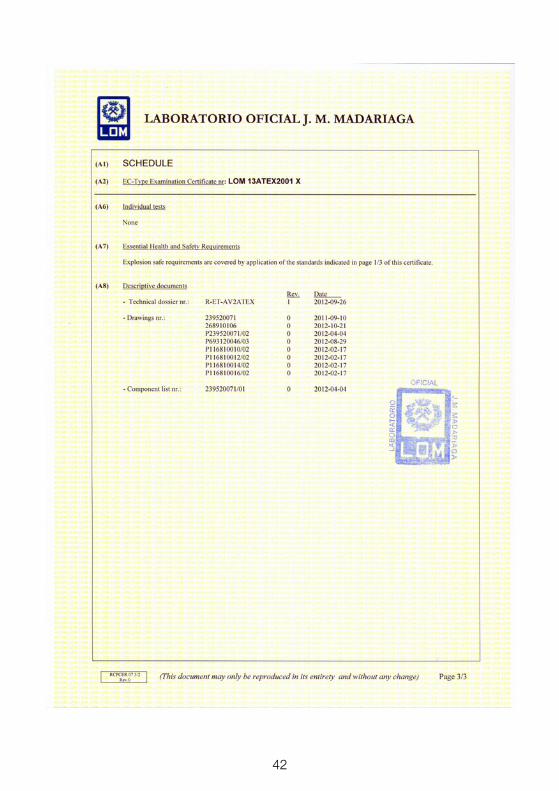
23 ATEX CERTIFICATE

41
42

43
24 DECLARATIONS OF CONFORMITY ACCORDING TO ATEX

44
WARRANTY
Tecfluid S.A. guarantee all the products for a period of 24 months from their sale, against all faulty materials, manufacturing or performance. This warranty does not cover failures which might be imputed to misuse, use in an application different to that specified in the order, the result of service or modification carried out by personnel not authorized by Tecfluid S.A., wrong handling or accident.
This warranty is limited to cover the replacement or repair of the defective parts which have not damaged due to misuse, being excluded all responsibility due to any other damage or the effects of wear caused by the normal use of the devices.
Any consignment of devices for repair must observe a procedure which can be consulted in the website www.tecfluid.com, “After-Sales” section.
All materials sent to our factory must be correctly packaged, clean and completely exempt of any liquid, grease or toxic substances.
The devices sent for repair must enclose the corresponding form, which can be filled in via website from the same “After-Sales” section.
Warranty for repaired or replaced components applies 6 months from repair or replacement date. Anyway, the warranty period will last at least until the initial supply warranty period is over.
TRANSPORTATION
All consignments from the Buyer to the Seller´s installations for their credit, repair or replacement must always be done at freight cost paid unless previous agreement.
The Seller will not accept any responsibility for possible damages caused on the devices during transportation.
Tecfluid S.A.
Narcís Monturiol 33
08960 Sant Just Desvern
Barcelona
Tel: +34 93 372 45 11
Fax: +34 93 473 44 49
www.tecfluid.com
The technical data described in this manual is subject to modification without notification if the technical innovations in the manufacturing processes so require.
Quality Management System ISO 9001 certified by
Pressure Equipment Directive 2014/68/UE certified by
ATEX European Directive 2014/34/EU certified by
HART® is a registered trademark of Fielcomm Group