102521 rev c - manuals - genie liftmanuals.gogenielift.com/parts and service...
TRANSCRIPT

Service Manual
Part No. 102521
Rev E
October 2013
Serial Number Range
from S40-7001 toS4012-17231S-40
S-45
TM
TM

S-40 • S-45 Part No. 102521
October 2013
ii
Introduction
Serial Number Information
Genie offers the following Service Manuals forthese models:
Title Part No.
S-40 and S-45 Service Manual(before serial number 3804) ................................ 32222
S-40 and S-45 Service Manual(from serial number 3804 to 4728) ....................... 52271
S-40 and S-45 Service Manual(from serial number 4729 to 7000) ....................... 72136
Copyright © 2011 by Terex Industries
102521 Rev E October 2013Fourth Edition, Fifth Printing
"Genie" and "S" are registered trademarks ofTerex South Dakota, Inc. in the USA and manyother countries.
Printed on recycled paper Printed in U.S.A.
Important
Read, understand and obey the safety rules andoperating instructions in the appropriate operator'smanual on your machine before attempting anymaintenance or repair procedure.
This manual provides detailed scheduledmaintenance information for the machine owner anduser. It also provides troubleshooting fault codesand repair procedures for qualified serviceprofessionals.
Basic mechanical, hydraulic and electrical skills arerequired to perform most procedures. However,several procedures require specialized skills, tools,lifting equipment and a suitable workshop. In theseinstances, we strongly recommend thatmaintenance and repair be performed at anauthorized Genie dealer service center.
Compliance
Machine ClassificationGroup B/Type 3 as defined by ISO 16368
Machine Design LifeUnrestricted with proper operation, inspection andscheduled maintenance.
Technical Publications
Genie has endeavored to deliver the highest degreeof accuracy possible. However, continuousimprovement of our products is a Genie policy.Therefore, product specifications are subject tochange without notice.
Readers are encouraged to notify Genie of errorsand send in suggestions for improvement. Allcommunications will be carefully considered forfuture printings of this and all other manuals.
Contact Us:
http://www.genielift.come-mail: [email protected]

Part No. 102521 S-40 • S-45
October 2013
Revision Date Section Procedure / Schematic Page / Description
D 2/2012 2 - Spec. 2-1, 2-2, 2-13
3 - Maint. 3-1, 3-3, 3-9 to 3-15, 3-17, 3-35 to 3-38, 3-54
4 - Repair 4-4, 4-5, 4-6, 4-7, 4-48, 4-49, 4-50, 4-51, 4-60
6 - Schem. 6-4, 6-5, 6-32 to 6-64, 6-92 to 6-125, 6-138,6-139, 6-150, 6-151, 6-153
D1 10/1012 2 - Spec. 2-1, 2-2
3 - Maint. 3-9, 3-33 to 3-34
4 - Repair 4-59 to 4-60
D2 10/2013 4- Repair 4-3
6 - Schem. 6-19, 6-29, 6-33, 6-93
REFERENCE EXAMPLES:
2-1_Section 2_Specifications Page #.3-3_Section 3_Maintenance Procedure Page #.4-48_Section 4_Repair Procedure Page #.Fault Codes_Section 5.6-5_Section 6_Schematic Page #.
Electronic Version
Click on any procedure or page numberhighlighted in blue to view the update.
Revision History

S-40 • S-45 Part No. 102521
October 2013
REVISION HISTORY, CONTINUED
Revision Date Section Procedure / Schematic Page / Description
REFERENCE EXAMPLES:
2-1_Section 2_Specifications Page #.3-3_Section 3_Maintenance Procedure Page #.4-48_Section 4_Repair Procedure Page #.Fault Codes_Section 5.6-5_Section 6_Schematic Page #.
Electronic Version
Click on any procedure or page numberhighlighted in blue to view the update.

Part No. 102521 S-40 • S-45
October 2013
S40 06 - 12345
Model
Model year
Sequencenumber
PN - 77055
Country of manufacture: USA
This machine complies with:
Genie Industries
18340 NE 76th Street
Redmond, WA 98052
USA
ANSI A92.5
CAN B.354.4
Model: S-40
Serial number: S4006-12345
Electrical schematic number: ES0274
Machine unladen weight:
Rated work load (including occupants): 500 lb / 227 kg
Maximum allowable inclination of the chassis:
0 deg
Gradeability: N/A
Maximum allowable side force : 150 lb / 670 N
Maximum number of platfrm occupants: 2
Model year: Manufacture date: 01/05/062006
Maximum wind speed : 28 mph/ 12.5 m/s
Maximum platform height : 60 ft 6 in/ 18.3 m
Maximum platform reach : 34 ft 3 in/ 10.4 m
Sequence number(stamped on chassis)
Serial label(located under cover)
iii
Section 1 • Safety Rules
Serial Number Legend

S-40 • S-45 Part No. 102521
July 2007
iv
This page intentionally left blank.
Section 1 • Safety Rules

Part No. 102521 S-40 • S-45
July 2007 Section 1 • Safety Rules
Safety Rules
DangerFailure to obey the instructions and safety rules inthis manual, and the Genie S-40 and S-45Operator's Manual will result in death or seriousinjury.
Many of the hazards identified in the operator'smanual are also safety hazards when maintenanceand repair procedures are performed.
Do Not Perform MaintenanceUnless:
You are trained and qualified to performmaintenance on this machine.
You read, understand and obey:- manufacturer’s instructions and safety rules- employer’s safety rules and worksiteregulations- applicable governmental regulations
You have the appropriate tools, lifting equipmentand a suitable workshop.
v

S-40 • S-45 Part No. 102521
July 2007
vi
SAFETY RULES
Personal SafetyAny person working on or around a machine mustbe aware of all known safety hazards. Personalsafety and the continued safe operation of themachine should be your top priority.
Read each procedure thoroughly. Thismanual and the decals on the machine usesignal words to identify the following:
Safety alert symbol—used to alertpersonnel to potential personalinjury hazards. Obey all safetymessages that follow this symbolto avoid possible injury or death.
Used to indicate the presence ofan imminently hazardous situationwhich, if not avoided, will result indeath or serious injury.
Used to indicate the presence of apotentially hazardous situationwhich, if not avoided, could resultin death or serious injury.
Used to indicate the presence of apotentially hazardous situationwhich, if not avoided, may result inminor or moderate injury.
Used to indicate the presence of apotentially hazardous situationwhich, if not avoided, may result inproperty damage.
Be sure to wear protective eye wear andother protective clothing if the situationwarrants it.
Be aware of potential crushing hazardssuch as moving parts, free swinging orunsecured components when lifting or
placing loads. Always wear approved steel-toedshoes.
Workplace SafetyBe sure to keep sparks, flames andlighted tobacco away from flammable andcombustible materials like battery gases
and engine fuels. Always have an approved fireextinguisher within easy reach.
Be sure that all tools and working areasare properly maintained and ready foruse. Keep work surfaces clean and free
of debris that could get into machine componentsand cause damage.
Be sure any forklift, overhead crane orother lifting or supporting device is fullycapable of supporting and stabilizing the
weight to be lifted. Use only chains or straps thatare in good condition and of ample capacity.
Be sure that fasteners intended for onetime use (i.e., cotter pins and self-lockingnuts) are not reused. These components
may fail if they are used a second time.
Be sure to properly dispose of old oil orother fluids. Use an approved container.Please be environmentally safe.
Be sure that your workshop or work areais properly ventilated and well lit.
Section 1 • Safety Rules July 2007
Part No. 102521 S-40 • S-45
October 2013
Table of Contents
Introduction
Important Information ................................................................................................... ii
Serial Number Legend ................................................................................................. iv
Section 1 Safety Rules
General Safety Rules .................................................................................................. v
Section 2 Rev Specifications
Machine Specifications .......................................................................................... 2 - 1
Hydraulic Oil Specifications ................................................................................... 2 - 2
Manifold Component Specifications ....................................................................... 2 - 5
Valve Coil Resistance Specifications ..................................................................... 2 - 5
Ford LRG-425 EFI Engine Specifications ............................................................... 2 - 6
Ford DSG-423 EFI Engine Specifications .............................................................. 2 - 7
Deutz F3L-1011F Engine Specifications ................................................................ 2 - 8
Deutz F3L-2011/Deutz D2011L03i Engine Specifications ....................................... 2 - 9
Perkins 704-30 Engine Specifications .................................................................. 2 - 10
Perkins 404-22 Engine Specifications .................................................................. 2 - 11
Machine Torque Specifications ............................................................................ 2 - 12
Hydraulic Hose and Fitting Torque Specifications ................................................ 2 - 13
SAE and Metric Fastener Torque Chart ............................................................... 2 - 14
Section 3 Rev Scheduled Maintenance Procedures
Introduction ............................................................................................................ 3 - 1
Pre-Delivery Preparation ........................................................................................ 3 - 3
Maintenance Inspection Report .............................................................................. 3 - 5
Checklist A Procedures
A-1 Inspect the Decals and Manuals .................................................................. 3 - 7
A-2 Perform Pre-operation Inspection ................................................................. 3 - 8
A-3 Perform Function Tests ................................................................................ 3 - 8
A-4 Perform Engine Maintenance ....................................................................... 3 - 9
vii

S-40 • S-45 Part No. 102521
October 2013
TABLE OF CONTENTS
viii
Section 3 Rev Scheduled Maintenance Procedures, continued
A-5 Inspect the Track Components, TRAX option .............................................. 3 - 9
A-6 Perform 30 Day Service ............................................................................. 3 - 10
A-7 Perform Engine Maintenance - Deutz and Ford Models .............................. 3 - 10
A-8 Replace the Drive Hub Oil .......................................................................... 3 - 11
A-9 Perform Engine Maintenance - Perkins Models .......................................... 3 - 12
A-10 Inspect the Fuel Filter/Water Separator - Diesel Models ............................. 3 - 12
A-11 Perform Engine Maintenance - Ford Models ............................................... 3 - 13
A-12 Grease the Turntable Rotation Bearing and Rotate Gear ............................ 3 - 14
A-13 Perform Engine Maintenance - Deutz 1011F Models .................................. 3 - 14
A-14 Perform Engine Maintenance - Ford Models ............................................... 3 - 15
Checklist B Procedures
B-1 Inspect the Battery ..................................................................................... 3 - 16
B-2 Inspect the Electrical Wiring ....................................................................... 3 - 17
B-3 Inspect the Air Filter ................................................................................... 3 - 18
B-4 Test the Key Switch ................................................................................... 3 - 19
B-5 Perform Engine Maintenance - Deutz and Perkins Models ......................... 3 - 19
B-6 Check the Exhaust System ....................................................................... 3 - 20
B-7 Check the Oil Cooler and Cooling Fins - Deutz Models............................... 3 - 20
B-8 Inspect the Tires, Wheels and Lug Nut Torque ........................................... 3 - 21
B-9 Check the Drive Hub Oil Level and Fastener Torque .................................. 3 - 22
B-10 Confirm the Proper Brake Configuration...................................................... 3 - 23
B-11 Check and Adjust the Engine RPM ............................................................ 3 - 24
B-12 Test the Engine Idle Select ........................................................................ 3 - 25
B-13 Test the Fuel Select Operation - Ford Models ............................................ 3 - 26
B-14 Test the Ground Control Override ............................................................... 3 - 27
B-15 Check the Directional Valve Linkeage ........................................................ 3 - 27
B-16 Test the Platform Self-leveling ................................................................... 3 - 28

Part No. 102521 S-40 • S-45
October 2013
ix
Section 3 Rev Scheduled Maintenance Procedures, continued
B-17 Test the Drive Brakes ................................................................................ 3 - 28
B-18 Test the Drive Speed - Stowed Position ..................................................... 3 - 29
B-19 Test the Drive Speed - Raised or Extended Position .................................. 3 - 29
B-20 Perform Hydraulic Oil Analysis ................................................................... 3 - 30
B-21 Test the Alarm Package (if equipped) and the Descent Alarm .................... 3 - 31
B-22 Inspect the Fuel and Hydraulic Tank Cap Venting System ......................... 3 - 32
B-23 Check the Track Tension and Fastener Torque - TRAX Option .................. 3 - 33
B-24 Perform Engine Maintenance - Ford Models ............................................... 3 - 34
Checklist C Procedures
C-1 Perform Engine Maintenance - Deutz and Perkins Models ......................... 3 - 35
C-2 Grease the Platform Overload Mechanism (if equipped) ............................. 3 - 36
C-3 Test the Platform Overload Mechanism (if equipped) ................................. 3 - 36
C-4 Replace the Engine Air Filter - Deutz and Perkins Models .......................... 3 - 39
C-5 Replace the Inline Fuel Strainer .................................................................. 3 - 39
C-6 Perform Engine Maintenance Ford Models ................................................. 3 - 40
Checklist D Procedures
D-1 Check the Boom Wear Pads ...................................................................... 3 - 41
D-2 Check the Turntable Rotation Bearing Bolts ............................................... 3 - 42
D-3 Check the Free-wheel Configuration ........................................................... 3 - 43
D-4 Replace the Drive Hub Oil .......................................................................... 3 - 45
D-5 Perform Engine Maintenance - Deutz Models ............................................. 3 - 46
D-6 Replace the Hydraulic Filters ...................................................................... 3 - 47
D-7 Inspect for Turntable Bearing Wear ............................................................ 3 - 48
Checklist E Procedures
E-1 Test or Replace the Hydraulic Oil ............................................................... 3 - 50
E-2 Grease the Steer Axle Wheel Bearings, 2WD Models ................................ 3 - 52
E-3 Perform Engine Maintenance - Deutz and Perkins Models ......................... 3 - 53
E-4 Perform Engine Maintenance - Ford Models ............................................... 3 - 54
E-5 Perform Engine Maintenance - Deutz and Perkins Models ......................... 3 - 54
TABLE OF CONTENTS

S-40 • S-45 Part No. 102521
October 2013
TABLE OF CONTENTS
Section 3 Rev Scheduled Maintenance Procedures, continued
E-6 Perform Engine Maintenance - Deutz and Perkins Models ......................... 3 - 55
E-7 Perform Engine Maintenance - Deutz Models ............................................. 3 - 56
E-8 Perform Engine Maintenance - Deutz Models ............................................. 3 - 56
E-9 Perform Engine Maintenance - Ford Models ............................................... 3 - 57
Section 4 Rev Repair Procedures
Introduction ............................................................................................................ 4 - 1
Platform Controls
1-1 ALC-500 Circuit Board .................................................................................. 4 - 2
1-2 Joysticks ..................................................................................................... 4 - 3
Platform Components
2-1 Platform Leveling Slave Cylinder .................................................................. 4 - 8
2-2 Platform Rotator ........................................................................................... 4 - 9
2-3 Platform Overload System ......................................................................... 4 - 11
Jib Boom Components
3-1 Jib Boom.................................................................................................... 4 - 14
3-2 Jib Boom Lift Cylinder ................................................................................ 4 - 15
Boom Components
4-1 Cable Track ................................................................................................ 4 - 16
4-2 Boom ......................................................................................................... 4 - 18
4-3 Boom Lift Cylinder ...................................................................................... 4 - 19
4-4 Boom Extension Cylinder ........................................................................... 4 - 20
4-5 Platform Leveling Master Cylinder .............................................................. 4 - 21
Engines
5-1 RPM Adjustment - Deutz Models ............................................................... 4 - 24
5-2 RPM Adjustment - Perkins Models............................................................. 4 - 24
5-3 Flex Plate................................................................................................... 4 - 24
5-4 Engine Fault Codes - Ford Models ............................................................. 4 - 28
x

Part No. 102521 S-40 • S-45
October 2013
Section 4 Rev Repair Procedures, continued
Hydraulic Pumps
6-1 Function Pump ........................................................................................... 4 - 29
6-2 Drive Pump ................................................................................................ 4 - 30
Manifolds
7-1 Function Manifold Components .................................................................. 4 - 32
7-2 Valve Adjustments - Function Manifold ...................................................... 4 - 36
7-3 Jib Select and Platform Rotate Manifold Components ................................ 4 - 37
7-4 Brake Manifold Components(before serial number 7569) ........................................................................ 4 - 38
7-5 Brake/Two-Speed Manifold Components(after serial number 7568) ........................................................................... 4 - 39
7-6 Oscillate Directional Valve Manifold Components....................................... 4 - 40
7-7 Valve Adjustments, Oscillate Relief Valve ................................................. 4 - 42
7-8 Traction Manifold Components, 2WD (before serial number 7569) .............. 4 - 43
7-9 Traction Manifold Components, 2WD (after serial number 7568) ................. 4 - 44
7-10 Valve Adjustments, 2WD Traction Manifold ............................................... 4 - 45
7-11 Traction Manifold Components, 4WD (before serial number 7569) .............. 4 - 46
7-12 Traction Manifold Components, 4WD (from serial number 7568 to 15822) .. 4 - 48
7-13 Traction Manifold Components, 4WD (from serial number 15823) ............... 4 - 50
7-14 Valve Adjustments, 4WD Traction Manifold ............................................... 4 - 52
7-15 Valve Coils ................................................................................................. 4 - 53
7-16 Drive Oil Diverter Manifold Components (welder option) ............................. 4 - 55
Turntable Rotation Components
8-1 Turntable Rotation Assembly ..................................................................... 4 - 56
Axle Components
9-1 Oscillate Axle Cylinders ............................................................................. 4 - 58
Track Components
10-1 Track Assembly - TRAX Option ................................................................. 4 - 59
Generators
10-1 Hydraulic Generator .................................................................................... 4 - 61
xi
TABLE OF CONTENTS

S-40 • S-45 Part No. 102521
October 2013
TABLE OF CONTENTS
Section 5 Rev Fault Codes
Introduction ............................................................................................................ 5 - 1
Fault Codes - Control System ................................................................................ 5 - 2
Fault Codes - Ford LRG-425 Engine....................................................................... 5 - 6
Fault Codes - Ford DSG-423 EFI Engine ............................................................. 5 - 12
Section 6 Rev Schematics
Introduction ............................................................................................................ 6 - 1
Electrical Symbols Legend .................................................................................... 6 - 2
Hydraulic Symbols Legend .................................................................................... 6 - 3
Ford DSG-423 Engine Relay Layout ....................................................................... 6 - 4
Connector Pin Legend ............................................................................................ 6 - 5
Electrical Schematic, Deutz F3L 1011 Models(before serial number 7544) .......................................................................... 6 - 8
Ground Control Box Wiring DiagramDeutz F3L-1011F Models ........................................................................... 6 - 11
Platform Control Box Wiring DiagramDeutz F3L-1011F Models ........................................................................... 6 - 14
Platform Control Box Switch Panel Wiring DiagramDeutz F3L-1011F Models ........................................................................... 6 - 15
Electrical Schematic, Perkins 704-30 Models(before serial number 7472) ........................................................................ 6 - 18
Ground Control Box Wiring DiagramPerkins 704-30 Models ............................................................................... 6 - 21
Platform Control Box Wiring DiagramPerkins 704-30 Models ............................................................................... 6 - 24
Platform Control Box Switch Panel Wiring DiagramPerkins 704-30 Models ............................................................................... 6 - 25
xii

Part No. 102521 S-40 • S-45
October 2013
xiii
Section 6 Rev Schematics, continued
Electrical Schematic,Deutz F3L-2011/Deutz D2011L03i Models(from serial number 7544 to 12509)Perkins 404-22 Models(from serial number7472 to 12509) ............................................................. 6 - 28
Electrical Schematic,Deutz F3L-2011/Deutz D2011L03i ModelsPerkins 404-22 Models (from serial number 12510 to 14831) ...................... 6 - 32
Electrical Schematic,Deutz F3L-2011/Deutz D2011L03i ModelsPerkins 404-22 Models (from serial number 14832 to 15662) ...................... 6 - 36
Electrical Schematic,Deutz F3L-2011/Deutz D2011L03i Models - ANSI / CSA / ASPerkins 404-22 Models (from serial number 15663 to 16419) ...................... 6 - 40
Electrical Schematic,Deutz F3L-2011/Deutz D2011L03i Models - CEPerkins 404-22 Models (from serial number 15663 to 16419) ...................... 6 - 44
Electrical Schematic,Deutz F3L-2011/Deutz D2011L03i Models - ANSI / CSA / ASPerkins 404-22 Models (from serial number 16420) .................................... 6 - 48
Electrical Schematic,Deutz F3L-2011/Deutz D2011L03i Models - CEPerkins 404-22 Models (from serial number 16420) .................................... 6 - 52
Ground Control Box Wiring Diagram,Deutz F3L-2011/Deutz D2011L03i ModelsPerkins 404-22 Models (before serial number 14832) ................................. 6 - 56
Ground Control Box Wiring Diagram,Deutz F3L-2011/Deutz D2011L03i ModelsPerkins 404-22 Models (from serial number 14832) .................................... 6 - 57
TABLE OF CONTENTS

S-40 • S-45 Part No. 102521
October 2013
xiv
Section 6 Rev Schematics, continued
Platform Control Box Wiring DiagramDeutz F3L-2011/Deutz D2011L03i ModelsPerkins 404-22 Models (before serial number 14832) ................................. 6 - 60
Platform Control Box Wiring DiagramDeutz F3L-2011/Deutz D2011L03i ModelsPerkins 404-22 Models (from serial number 14832) .................................... 6 - 61
Platform Control Box Switch Panel Wiring DiagramDeutz F3L-2011/Deutz D2011L03i Models(from serial number 7544 to 12509)Perkins 404-22 Models(from serial number 7472 to 12509) ............................................................ 6 - 64
Platform Control Box Switch Panel Wiring DiagramDeutz F3L-2011/Deutz D2011L03i ModelsPerkins 404-22 Models (from serial number 12510) .................................... 6 - 65
Electrical Schematic,Ford LRG-425 EFI Models (before serial number 7597) .............................. 6 - 68
Ground Control Box Wiring Diagram,Ford LRG-425 EFI Models (before serial number 7597) .............................. 6 - 71
Platform Control Box Wiring DiagramFord LRG-425 EFI Models (before serial number 7597) .............................. 6 - 74
Platform Control Box Switch Panel Wiring DiagramFord LRG-425 EFI Models (before serial number 7597) .............................. 6 - 75
Electrical Schematic,Ford LRG-425 EFI Models(from serial number 7597 to 11066) ............................................................ 6 - 78
Ground Control Box Wiring Diagram,Ford LRG-425 EFI Models(from serial number 7597 to 11066) ............................................................ 6 - 81
Platform Control Box Wiring DiagramFord LRG-425 EFI Models(from serial number 7597 to 11066) ............................................................ 6 - 84
TABLE OF CONTENTS

Part No. 102521 S-40 • S-45
October 2013
Section 6 Rev Schematics, continued
Platform Control Box Switch Panel Wiring DiagramFord LRG-425 EFI Models(from serial number 7597 to 11066) ............................................................ 6 - 85
Electrical Schematic, Ford DSG-423 EFI Models(from serial number 11067 to 12509) .......................................................... 6 - 88
Electrical Schematic, Ford DSG-423 EFI Models(from serial number 12510 to 14831) .......................................................... 6 - 92
Electrical Schematic, Ford DSG-423 EFI Models(from serial number 12510 to 15662) .......................................................... 6 - 96
Electrical Schematic, Ford DSG-423 EFI Models - ANSA / CSA / AS(from serial number 15663 to 16419) .........................................................6 - 100
Electrical Schematic, Ford DSG-423 EFI Models - CE(from serial number 15663 to 16419) .........................................................6 - 104
Electrical Schematic, Ford DSG-423 EFI Models - ANSA / CSA / AS(from serial number 16420) ........................................................................6 - 108
Electrical Schematic, Ford DSG-423 EFI Models - CE(from serial number 16420) ........................................................................6 - 112
Ground Control Box Wiring Diagram,Ford DSG-423 EFI Models (before serial number 14832) ...........................6 - 116
Ground Control Box Wiring Diagram,Ford DSG-423 EFI Models (from serial number 14832)..............................6 - 117
Platform Control Box Wiring DiagramFord DSG-423 EFI Models (before serial number 14832) ...........................6 - 120
Platform Control Box Wiring DiagramFord DSG-423 EFI Models (from serial number 14832)..............................6 - 121
Platform Control Box Switch Panel Wiring Diagram,Ford DSG-423 EFI Models (from serial number 11067 to 12509) ...............6 - 124
Platform Control Box Switch Panel Wiring DiagramFord DSG-423 EFI Models (from serial number 12510)..............................6 - 125
TABLE OF CONTENTS

S-40 • S-45 Part No. 102521
October 2013
TABLE OF CONTENTS
Section 6 Rev Schematics, continued
Engine Harness, Ford LRG-425 EFI Models(before serial number 11067) .....................................................................6 - 128
Engine Harness, Ford DSG-423 EFI Models(from serial number 11067 to 11784) .........................................................6 - 129
Engine Harness, Ford DSG-423 EFI Models(from serial number 11785) ........................................................................6 - 132
Joystick Connector Diagram ...............................................................................6 - 133
CTE Option Wiring Diagram ................................................................................6 - 136
MTE Hydraulic Generator Option Wiring Diagram ................................................6 - 138
Hydraulic Generator Wiring Diagram (welder option) ............................................6 - 139
Hydraulic Schematic, 2WD Non-oscillating S-40 Models(before serial number 7569) .......................................................................6 - 142
Hydraulic Schematic, 2WD Non-oscillating S-45 Models(before serial number 7569) .......................................................................6 - 143
Hydraulic Schematic, 4WD Oscillating S-40 Models(before serial number 7569) .......................................................................6 - 146
Hydraulic Schematic, 4WD Oscillating S-45 Models(before serial number 7569) .......................................................................6 - 147
Hydraulic Schematic, 2WD (from serial number 7569) ........................................6 - 150
Hydraulic Schematic, 4WD (from serial number 7569) ........................................6 - 151
Generator Hydraulic Schematic (welder option) ...................................................6 - 153

Part No. 102521 S-40 • S-45 2 - 1
Section 2 • SpecificationsOctober 2013
Specifications
Machine SpecificationsS-40 and S-45 Models
Tires and wheels
Tire size, 2WDfront tires only 12.5L-16SLrear tires only 12-16.5 NHS
Tire size,2WDRT & 4WD front & rear 12-16.5 NHS
Tire weight, new foam-filled (minimum) 300 lbs(Rough terrain) 136 kg
Tire ply rating 12 8
Tire contact area 88 sq in 57 sq in568 sq cm 368 sq cm
Overall tire diameter 33.7 in 33.2 in85.6 cm 84.3 cm
Tire pressure 45 psi 45 psi(Rough terrain) 3.1 bar 3.1 bar
Tire pressure 60 psi 60 psi(Rough terrain) 4.1 bar 4.1 bar
Wheel diameter 16 in 161/2 in40.6 cm 41.9 cm
Wheel width 10 in 9 3/4 in25.4 cm 24.8 cm
Wheel lugs 8@ 5/8 -18 9@ 5/8 -18
Lug nut torque - Drive and 9-bolt non-drive hubs
Lug nut, dry 230 ft-lbs312 Nm
Lug nut, lubricated 170 ft-lbs230 Nm
Lug nut torque - 8-bolt non-drive spindles
Lug nut, dry 170 ft-lbs230 Nm
Lug nut, lubricated 130 ft-lbs176 Nm
Track Components, TRAX option
Track material Rubber
Weight, assembly (each) 480 lbs218 kg
Fluid capacities
Fuel tank 20 gallons75.7 liters
Fuel tank, Option 30 gallons114 liters
LPG tank 33.5 pounds15.2 kg
Hydraulic tank 45 gallons170 liters
Hydraulic system 55 gallons(including tank) 208 liters
Drive hub 17 fl oz(before serial number 7569) 0.5 liters
Drive hub 24 fl oz(from serial number 7569 to 15677) 0.71 liters
Drive hub 20 fl oz(from serial number 15678) 0.6 liters
Turntable rotation 8 fl ozdrive hub 0.24 liters
Drive hub oil type:SAE 90 multipurpose hypoid gear oil API serviceclassification GL5
For operational specifications, refer to theOperator's Manual.
Continuous improvement of our products is a Geniepolicy. Product specifications are subject to changewithout notice.

2 - 2 S-40 • S-45 Part No. 102521
Section 2 • Specifications October 2013
SPECIFICATIONS
Continuous improvement of our products is aGenie policy. Product specifications are subjectto change without notice.
Performance SpecificationsAll Models
Drive speeds, 2WD and 4WD
Drive speed, stowed 40 ft / 5.2 - 5.9 sec12.2 m / 5.2 - 5.9 sec
Drive speed, raised or extended 40 ft / 40 - 45 sec12.2 m / 40 - 45 sec
Drive speed, TRAX option
Drive speed, stowed 40 ft / 11 sec12.2 m / 11 sec
Drive speed, raised or extended 40 ft / 40 sec12.2 m / 40 sec
Gradeability See Operator's Manual
Boom function speeds, maximumfrom platform controls
Boom up 50 to 60 seconds
Boom down 45 to 60 seconds
Boom extend 30 to 60 seconds
Boom retract 15 to 35 seconds
Turntable rotate, 360°boom fully stowed 70 to 100 seconds
Turntable rotate, 360°boom fully extended 120 to 140 seconds
Platform level (10° range of motion)ANSI 3 to 5 secondsCE/Austrailia 20 to 22 seconds
Jib boom up, S-45 models 35 to 45 seconds
Jib boom down, S-45 models 20 to 30 seconds
Braking distance, maximum
High range on paved surface 3 to 4 ft0.9 to 1.2 m
Hydraulic Oil Specifications
Hydraulic Oil Specifications
Hydraulic oil type Chevron Rando HD MV equivalentViscosity grade Multi-viscosityViscosity index 200
Cleanliness level, minimum 15/13
Water content, maximum 200 ppm
Chevron Rando HD MV oil is fully compatible andmixable with Shell Donax TG (Dexron III) oils.Genie specifications require hydraulic oils which aredesigned to give maximum protection to hydraulicsystems, have the ability to perform over a widetemperature range, and the viscosity index shouldexceed 140. They should provide excellent antiwear,oxidation, corrosion inhibition, seal conditioning, andfoam and aeration suppression properties.
Optional fluids
Biodegradable Petro Canada Environ MV46Statoil Hydra Way Bio Pa 32
BP Biohyd SE-S
Fire resistant UCON Hydrolube HP-5046Quintolubric 822
Mineral based Shell Tellus S2 V 32Shell Tellus S2 V 46Chevron Aviation A
Eni Arnica 32

Part No. 102521 S-40 • S-45 2 - 3
Section 2 • SpecificationsOctober 2013
Hydraulic ComponentSpecifications
Drive pump
Type: bi-directional,variable displacement piston pump
Displacement per revolution, variable, 4WD models 0 to 2.8 cu in
0 to 46 cc
Flow rate @ 2500 rpm 0 to 28 gpm106 L/min
Drive pressure, maximum 3625 psi250 bar
Charge pump
Type: gerotor pump
Displacement 0.85 cu in13.9 cc
Flow rate @ 2500 rpm 9 gpm34.1 L/min
Charge pressure @ 2500 rpm 310 psiNeutral position 21.4 bar
Function pump
Type gear, pressure balanced
Displacement 1.04 cu in17 cc
Flow rate @ 2500 rpm 10.69 gpm40.5 L/min
Oscillation pump
Type gear, fixed displacement
Displacement 0.37 cu in6 cc
Flow rate @ 2500 rpm 2.8 gallons per minute10.6 liters per minute
Continued use of Chevron AviationA hydraulic oil when ambienttemperatures are consistentlyabove 32°F / 0°C may result incomponent damage.
Note: Use Chevron Aviation A hydraulic oil whenambient temperatures are consistentlybelow 0°F / -18°C.
Note: Use Shell Tellus S2 V 46 hydraulic oil whenoil temperatures consistently exceed 205°F / 96°C.
Note: Genie specifications require additionalequipment and special installation instructions forthe approved optional fluids. Consult the GenieIndustries Service Department before use.
SPECIFICATIONS
Continuous improvement of our products is aGenie policy. Product specifications are subjectto change without notice.

2 - 4 S-40 • S-45 Part No. 102521
Section 2 • Specifications October 2013
SPECIFICATIONS
Steer-end drive motors, 4WD(before serial number 7569)
Displacement per revolution 1.52 cu in / 25 cc
Non-steer end drive motors, 2WD and 4WD(before serial number 7569)
Displacement per revolution 2.13 cu in / 35 cc
Two-speed drive motors, 2WD and 4WD(after serial number 7568)
Displacement per revolution 0.99 cu in / 16.3 cclow speed
Displacement per revolution 1.83 cu in / 30 cchigh speed
Hydraulic Filters
Medium pressure filter Beta 3 ≥ 200
Medium pressure filter 51 psibypass pressure 3.5 bar
Hydraulic tank circuit 10 micron withreturn line filter 25 psi / 1.7 bar bypass
Auxiliary pump
Type: fixed displacement gear pump
Displacement - static 0.151 cu in2.47 cc
Displacement 1.75 gallons per minute6.62 liters per minute
Function manifold
Function relief valve pressureS-40 2600 psi / 179 barS-45 2900 psi / 200 bar
Boom down 2200 psirelief valve pressure 152 bar
Boom extend 1950 psi134 bar
Oscillate axle 950 psi66 bar
Steer regulator, 2 gallons per minuteAll models 7.6 liters per minute
Traction manifold, 2WD and 4WD(before serial number 7569)
Hot oil relief pressure 210 psi14.5 bar
Traction manifold, 2WD and 4WD(after serial number 7568)
Hot oil relief pressure 280 psi19.3 bar
Continuous improvement of our products is aGenie policy. Product specifications are subjectto change without notice.

Part No. 102521 S-40 • S-45 2 - 5
Section 2 • SpecificationsOctober 2013
Continuous improvement of our products is aGenie policy. Product specifications are subjectto change without notice.
Manifold ComponentSpecifications
Plug torque
SAE No. 2 36 in-lbs / 4.1 Nm
SAE No. 4 10 ft-lbs / 13.6 Nm
SAE No. 6 14 ft-lbs / 19 Nm
SAE No. 8 38 ft-lbs / 51.5 Nm
SAE No. 10 41 ft-lbs / 55.6 Nm
SAE No. 12 56 ft-lbs / 75.9 Nm
SPECIFICATIONS
Valve Coil ResistanceSpecificationsNote: The following coil resistance specificationsare at an ambient temperature of 68°F / 20°C. Asvalve coil resistance is sensitive to changes in airtemperature, the coil resistance will typicallyincrease or decrease by 4% for each 18°F / 20°Cthat your air temperature increases or decreasesfrom 68°F / 20°C.
Description Specification
Solenoid valve, 2 position 3 way, 10V DC 6.3 Ω(schematic items AC and AE)
Solenoid valve, 3 position 4 way, 10V DC 6.3 Ω(schematic item AT and AZ)
Solenoid valve, 2 position 3 way, 10V DC 6.3 Ω(schematic items AU, AV, AX, and AY)
Solenoid valve, 3 position 4 way, 10V DC 6.3 Ω(schematic items AZ and BF)
Proportional solenoid valve, 12V DC 9 Ω(schematic items AW and BB)
Solenoid valve, 2 position 3 way, 10V DC 6.8 Ω(schematic item CC)
Solenoid valve, 2 position 3 way, 10V DC 3.3 Ω(schematic items DA)
Solenoid valve, 2 position 3 way, 12V DC 4.8 Ω(schematic items CE)
2 - 6 S-40 • S-45 Part No. 102521
Section 2 • Specifications October 2013
SPECIFICATIONS
Ford LRG-425 EFI Engine
Displacement 153 cu in2.5 liters
Number of cylinders 4
Bore & stroke 3.78 x 3.4 in96.01 x 86.36 mm
HorsepowerGross intermittent 70 @ 2500 rpmContinuous 60 @ 2500 rpmGross intermittent 52 kW @ 2500 rpmContinuous 44.7 kW @ 2500 rpm
Firing order 1 - 3 - 4 - 2
Low idle rpm 1600 rpmFrequency 396.8 Hz
High idle rpm 2500 rpmFrequency 620 Hz
Compression ratio 9.4:1
Compression pressure (approx.)Pressure (psi) of lowest cylinder must beat least 75% of highest cylinder
Valve clearances - 0.035 to 0.055 incollapsed tappet 0.889 to 1.397 mm
Lubrication system
Oil pressure 40 to 60 psi(operating temp. @ 2000 rpm) 2.75 to 4.1 bar
Oil capacity 4.5 quarts(including filter) 4.3 liters
Oil viscosity requirements
Unit ships with 5W-30 oil.Extreme operating temperatures may require the use ofalternative engine oils. For oil requirements, refer to theengine Operator's Manual on your machine.
Oil pressure switch specifications
Torque 8-18 ft-lbs11-24 Nm
Oil pressure switch point 3-5 psi0.21-0.34 bar
Starter motor
Normal engine cranking speed 200 to 250 rpm
Current draw, normal load 140-200A
Current draw, maximum load 800A
Current draw, no load 70A
Battery
Type 12V DC, Group 31
Quantity 1
Cold cranking ampere 1000A
Reserve capacity @ 25A rate 200 minutes
Electronic fuel pump
Fuel pressure, static 64 psi4.4 bar
Fuel flow rate 0.58 gpm2.18 L/min
Ignition System
Spark plug type Motorcraft AWSF-52-C(before serial number 4546)
Spark plug type Motorcraft AGSF-32-FM(after serial number 4545)
Spark plug gap 0.042 to 0.046 inches1.07 to 1.17 mm
Spark plug torque 5-10 ft-lbs7-14 Nm
Engine coolant
Capacity 11.5 quarts10.9 liters
Coolant temperature switch
Torque 8-18 ft-lbs11-24 Nm
Temperature switch point 230° F112° C
Alternator

Part No. 102521 S-40 • S-45 2 - 7
Section 2 • SpecificationsOctober 2013
Ford DSG-423 EFI Engine
Displacement 140.4 cu in2.3 liters
Number of cylinders 4
Bore & stroke 3.44 x 3.7 inches87.5 x 94 mm
HorsepowerContinuous horsepower 59 @ 2500 rpmPeak horsepower 69 @ 2500 rpmContinuous horsepower 44 kW @ 2500 rpmPeak horsepower 51 kW @ 2500 rpm
Firing order 1 - 3 - 4 - 2
Low function idle (computer controlled) 1600 rpmFrequency 53.3 Hz
High function idle (computer controlled) 2500 rpmFrequency 83.3 Hz
Compression ratio 9.7:1
Compression pressure (approx.)Pressure (psi or bar) of lowest cylinder must beat least 75% of highest cylinder
Lubrication system
Oil pressure 29 to 39 psi(at operating temperature @ 2500 rpm) 2 to 2.7 bar
Oil capacity 4 quarts(including filter) 3.8 liters
Oil viscosity requirements
Unit ships with 5-W20 oil.Extreme operating temperatures may require the use ofalternative engine oils. For oil requirements, refer to theengine Operator's Manual on your machine.
Electronic fuel pump
Fuel pressure, static 64 psi4.4 bar
Fuel flow rate 0.43 gpm1.6 L/min
Fuel requirement
For fuel requirements, refer to the engine Operator'sManual on your machine.
Ignition system
Spark plug type Motorcraft AGSF-32-FEC
Spark plug gap 0.049 to 0.053 inches1.244 to 1.346 mm
Engine coolant
Capacity 10 quarts9.5 liters
Cylinder head temperature sending unit
Fault code set temperature 280°F138°C
Engine shut-down temperature 300°F149°C
Starter motor
Normal engine cranking speed 200 to 250 rpm
Current draw, normal load 140-200A
Current draw, maximum load 800A
Alternator
Output 95A, 13.8V DC
Battery
Type 12V DC, Group 31
Quantity 1
Cold cranking ampere @ 0°F 1000A
Reserve capacity @ 25A rate 200 minutes
Continuous improvement of our products is aGenie policy. Product specifications are subjectto change without notice.
SPECIFICATIONS

2 - 8 S-40 • S-45 Part No. 102521
Section 2 • Specifications October 2013
SPECIFICATIONS
Injection system
Injection pump make OMAP
Injection pump pressure 4351 psi300 bar
Injector opening pressure 3626 psi250 bar
Fuel requirement
For fuel requirement, refer to the engine Operator'sManual on your machine.
Alternator output 55A, 14V
Starter motor
Current draw, no load 90A
Brush length, new 0.7480 in19 mm
Brush length, minimum 0.5 in12.7 mm
Battery
Type 12V, Group 31
Quantity 1
Cold cranking ampere 1000A
Reserve capacity @ 25A rate 200 minutes
Fan belt deflection 3/8 to 1/2 inch9 to 12 mm
Deutz F3L-1011F Engine
Displacement 125 cu in2.05 liters
Number of cylinders 3
Bore and stroke 3.58 x 4.13 inches91 x 105 mm
Horsepower 36 @ 3000 rpm26.8 kW @ 3000 rpm
Firing order 1 - 2 - 3
Compression ratio 18.5:1
Compression pressure 362 to 435 psi25 to 30 bar
Low idle rpm 1500 rpmFrequency 313 Hz
High idle rpm 2300 rpmFrequency 479.9 Hz
Governor centrifugal mechanical
Valve clearance, cold
Intake 0.012 in0.3 mm
Exhaust 0.020 in0.5 mm
Lubrication system
Oil pressure 26 to 87 psi1.8 to 6.0 bar
Oil capacity 8.5 quarts(including filter) 8 liters
Oil viscosity requirements
Temperature below 60°F / 15.5°C (synthetic) 5W-30
-10°F to 90°F / -23°C to 32°C 10W-40
Temperature above -4°F / -34°C 15W-40
Extreme operating temperatures may require the use ofalternative engine oils. For oil requirements, refer to theengine Operator's Manual on your machine. Continuous improvement of our products is a
Genie policy. Product specifications are subjectto change without notice.

Part No. 102521 S-40 • S-45 2 - 9
Section 2 • SpecificationsOctober 2013
SPECIFICATIONS
Deutz F3L-2011 EngineDeutz D2011L03i Engine
Displacement 142 cu in2.33 liters
Number of cylinders 3
Bore and stroke 3.7 x 4.4 inches94 x 112 mm
Horsepower
Net intermittent 48.7 @ 2800 rpmNet continuous 46.2 @ 2800 rpmNet intermittent 36 kW @ 2800 rpmNet continuous 34.5 kW @ 2800 rpm
Firing order 1 - 2 - 3
Low idle rpm 1500 rpmFrequency 313 Hz
High idle rpm 2500 rpmFrequency 521.7 Hz
Compression ratio 19:1
Compression pressure 362 to 435 psi25 to 30 bar
Governor centrifugal mechanical
Valve clearance, cold
Intake 0.012 in0.3 mm
Exhaust 0.020 in0.5 mm
Lubrication system
Oil pressure, hot @ 2000 rpm 40-60 psi2.8 to 4.1 bar
Oil capacity 8.5 quarts(including filter) 8 liters(Deutz F3L2011 Engine)
Oil capacity 9.5 quarts(including filter) 9 liters(Deutz D2011L03i Engine)
Oil viscosity requirements
Unit ships with 15-W40 oil.Extreme operating temperatures may require the use ofalternative engine oils. For oil requirements, refer to theengine Operator's Manual on your machine.
Oil temperature switch
Torque 8-18 ft-lbs11-24 Nm
Temperature switch point 220° F104° C
Oil pressure switch
Torque 8-18 ft-lbs11-24 Nm
Oil pressure switch point 7 psi(Deutz F3L2011 Engine) .5 bar
Oil pressure switch point 22 psi(Deutz D2011L03i Engine) 1.5 bar

2 - 10 S-40 • S-45 Part No. 102521
Section 2 • Specifications October 2013
Fuel injection system
Injection pump make Bosch
Injection pump pressure, maximum 15000 psi1034 bar
Injector opening pressure 3046 psi210 bar
Fuel requirement
For fuel requirement, refer to the engine Operator'sManual on your machine.
Starter motor
Current draw, normal load 140-200A
Brush length, new 0.72 in18.5 mm
Brush length, minimum 0.27 in7 mm
Battery
Type 12V, Group 31
Quantity 1
Cold cranking ampere 1000A
Reserve capacity @ 25A rate 200 minutes
Alternator output 60A @ 14V DC
Fan belt deflection 3/8 to 1/2 inch9 to 12 mm
SPECIFICATIONS

Part No. 102521 S-40 • S-45 2 - 11
Section 2 • SpecificationsOctober 2013
SPECIFICATIONS
Perkins 704-30 Engine
Displacement 183 cu in2.9 liters
Number of cylinders 4
Bore and stroke 3.82 x 3.94 inches97 x 100 mm
Horsepower 63 @ 2600 rpm47 kW @ 2600 rpm
Firing order 1 - 3 - 4 - 2
Compression ratio 17.5:1
Compression pressure 300 to 500 psi20.7 to 34.5 bar
Pressure (psi) of lowest cylinder must be within50 psi (3.45 bar) of highest cylinder
Low idle rpm 1600 rpmFrequency 246.7 Hz
High idle rpm 2200 rpmFrequency 339.2 Hz
Governor centrifugal mechanical
Valve clearance, cold
Intake 0.014 in0.35 mm
Exhaust 0.014 in0.35 mm
Lubrication system
Oil pressure 41 psi(at 2600 rpm) 2.8 bar
Oil capacity 7.3 quarts(including filter) 8.3 liters
Oil viscosity requirements
below 68°F / 20°C (synthetic) 5W-20
5°F to 104°F / -15°C to 40°C 10W-30
above 14°F / -10°C 15W-40
Engine oil should have properties of API classificationCC/SE. API classification CD/SE or CCMC D4 can beused, but is not recommended during the first 50 hoursnor for light load applications.
Injection system
Injection pump make Zexel PFR-KX
Injection pump pressure(stage one) 2755 psi 190 bar(stage two) 3336 psi 230 bar
Injector opening pressure 3626 psi 250 bar
Fuel requirement
For fuel requirement, refer to the engine Operator'sManual on your machine.
Engine coolant
Capacity 111/2 quarts10.9 liters
Alternator output 65A, 12V
Battery
Type 12V, Group 31
Quantity 1
Cold cranking ampere 1000A
Reserve capacity @ 25A rate 200 minutes
Fan belt deflection 3/8 in10 mm

2 - 12 S-40 • S-45 Part No. 102521
Section 2 • Specifications October 2013
Perkins 404-22 Engine
Displacement 134 cu in2.2 liters
Number of cylinders 4
Bore and stroke 3.31 x 3.94 inches84 x 100 mm
Horsepower
gross intermittent 50 @ 2800 rpmcontinuous 41 @ 2800 rpmgross intermittent 37.3 kW @ 2800 rpmcontinuous 31 kW @ 2800 rpm
Firing order 1 - 3 - 4 - 2
Low idle rpm 1300 rpmFrequency 200.5 Hz
Low Idle rpm with generator option 1500 rpmFrequency 231.3 Hz
High idle rpm 2500 rpmFrequency 385.5 Hz
Compression ratio 22.4:1
Compression pressure 426 psi29.4 bar
Pressure (psi) of lowest cylinder mustbe within 50 psi / 3.45 bar of highest cylinder
Governor centrifugal mechanical
Valve clearance, cold
Intake 0.008 in0.2 mm
Exhaust 0.008 in0.2 mm
Lubrication system
Oil pressure, hot 40 to 60 psi(at 2000 rpm) 2.8 to 4.1 bar
Oil capacity 9.4 quarts to 11.2 quarts(including filter) 8.9 liters to 10.6 liters
Oil viscosity requirements
Unit ships with 15-W40 oil.Extreme operating temperatures may require the use ofalternative engine oils. For oil requirements, refer to theengine Operator's Manual on your machine.
Oil pressure sending unit
Torque 8-18 ft-lbs11-24 Nm
Oil pressure switch point 14.2 psi1 bar
Coolant temperature sending unit
Torque 8-18 ft-lbs11-24 Nm
Temperature switch point 221° F 105° C
Fuel injection system
Injection pump make Zexel
Injection pressure 2133 psi147 bar
Fuel requirement
For fuel requirement, refer to the engine Operator'sManual on your machine.
Battery
Type 12V, Group 31
Quantity 1
Cold cranking ampere 1000A
Reserve capacity @ 25A rate 200 minutes
Starter motor
Current draw, normal load 140-200A
Alternator output 65A @ 13.8V DC
Fan belt deflection 3/8 to ½ in9 to 12 mm
SPECIFICATIONS
Part No. 102521 S-40 • S-45 2 - 13
Section 2 • SpecificationsOctober 2013
SPECIFICATIONS
Machine Torque Specifications
Platform rotator
1-8 center bolt, Gr 5, dry 640 ft-lbs868 Nm
1-8 center bolt, Gr 5, lubricated 480 ft-lbs651 Nm
3/8 -16 bolts, Gr 8, lubricated 35 ft-lbs**use blue thread-locking compound 47.5 Nm
Turntable rotator
Drive hub mounting bolts, dry 210 ft-lbs284 Nm
Drive hub mounting bolts, lubricated* 160 ft-lbs*use blue thread-locking compound 217 Nm
Drive motor and hubs
Drive hub mounting bolts, dry 210 ft-lbs284 Nm
Drive hub mounting bolts, lubricated 160 ft-lbs**use blue thread-locking compound 217 Nm
Drive motor mounting bolts, dry 49 ft-lbs66.4 Nm
Drive motor mounting bolts, lubricated 37 ft-lbs50 Nm
Turntable bearing
Turntable bearing mounting bolts, lubricated 180 ft-lbs244 Nm
TRAX Torque Specifications
Hub to drive sprocket fasteners
Lug nut, dry 230 ft-lbs312 Nm
Lug nut, lubricated 170 ft-lbs230 Nm
Idler and bogey wheel fasteners
3/4 -10 bolts, GR 8, dry 375 ft-lbs508 Nm
3/4 -10 bolts, GR 8, lubricated 281 ft-lbs381 N

2 - 14 S-40 • S-45 Part No. 102521
Section 2 • Specifications October 2013
Hydraulic Hose and FittingTorque SpecificationsYour machine is equipped with Parker Seal-Lok®
fittings and hose ends. Genie specifications requirethat fittings and hose ends be torqued tospecification when they are removed and installedor when new hoses or fittings are installed.
Seal-Lok® fittings
1 Replace the O-ring. The O-ring must be replacedanytime the seal has been broken. The O-ringcannot be re-used if the fitting or hose end hasbeen tightened beyond finger tight.
Note: The O-rings used in the Parker Seal Lok®fittings and hose ends are custom-size O-rings.They are not standard SAE size O-rings. They areavailable in the O-ring field service kit (Genie partnumber 49612).
2 Lubricate the O-ring before installation.
3 Be sure that the face seal O-ring is seated andretained properly.
4 Position the tube and nut squarely on the faceseal end of the fitting and tighten the nut fingertight.
5 Tighten the nut or fitting to the appropriatetorque per given size as shown in the table.
6 Operate all machine functions and inspect thehoses and fittings and related components toconfirm that there are no leaks.
SAE O-ring Boss Port(tube fitting - installed into Aluminum)
SAE Dash size Torque
-4 14 ft-lbs / 18.9 Nm
-6 23 ft-lbs / 31.2 Nm
-8 36 ft-lbs / 48.8 Nm
-10 62 ft-lbs / 84.1 Nm
-12 84 ft-lbs / 113.9 Nm
-16 125 ft-lbs / 169.5 Nm
-20 151 ft-lbs / 204.7 Nm
-24 184 ft-lbs / 250 Nm
SAE O-ring Boss Port(tube fitting - installed into Steel)
SAE Dash size Torque
-4 15 ft-lbs / 20.3 Nm
-6 35 ft-lbs / 47.5 Nm
-8 60 ft-lbs / 81.3 Nm
-10 100 ft-lbs / 135.6 Nm
-12 135 ft-lbs / 183 Nm
-16 200 ft-lbs / 271 Nm
-20 250 ft-lbs / 334 Nm
-24 305 ft-lbs / 414 Nm
Seal-Lok® Fittings (ORFS)(hose end)
SAE Dash size Torque
-4 18 ft-lbs / 24.4 Nm
-6 30 ft-lbs / 40.7 Nm
-8 40 ft-lbs / 54.2 Nm
-10 60 ft-lbs / 81.3 Nm
-12 85 ft-lbs / 115 Nm
-16 110 ft-lbs / 149 Nm
-20 140 ft-lbs / 190 Nm
-24 180 ft-lbs / 244 Nm
SPECIFICATIONS

Part No. 102521 S-40 • S-45 2 - 15
Section 2 • SpecificationsOctober 2013
SIZE THREAD
in-lbs Nm in-lbs Nm in-lbs Nm in-lbs Nm in-lbs Nm20 80 9 100 11.3 110 12.4 140 15.8 130 14.728 90 10.1 120 13.5 120 13.5 160 18 140 15.8
ft-lbs Nm ft-lbs Nm ft-lbs Nm ft-lbs Nm ft-lbs Nm
18 13 17.6 17 23 18 24 25 33.9 21 28.424 14 19 19 25.7 20 27.1 27 36.6 24 32.516 23 31.2 31 42 33 44.7 44 59.6 38 51.524 26 35.2 35 47.4 37 50.1 49 66.4 43 58.314 37 50.1 49 66.4 50 67.8 70 94.7 61 82.720 41 55.5 55 74.5 60 81.3 80 108.4 68 92.113 57 77.3 75 101.6 80 108.4 110 149 93 12620 64 86.7 85 115 90 122 120 162 105 14212 80 108.4 110 149 120 162 150 203 130 17618 90 122 120 162 130 176 170 230 140 18911 110 149 150 203 160 217 210 284 180 24418 130 176 170 230 180 244 240 325 200 27110 200 271 270 366 280 379 380 515 320 43316 220 298 300 406 310 420 420 569 350 4749 320 433 430 583 450 610 610 827 510 69114 350 474 470 637 500 678 670 908 560 7598 480 650 640 867 680 922 910 1233 770 104412 530 718 710 962 750 1016 990 1342 840 11397 590 800 790 1071 970 1315 1290 1749 1090 147712 670 908 890 1206 1080 1464 1440 1952 1220 16547 840 1138 1120 1518 1360 1844 1820 2467 1530 207412 930 1260 1240 1681 1510 2047 2010 2725 1700 23046 1460 1979 1950 2643 2370 3213 3160 4284 2670 362012 1640 2223 2190 2969 2670 3620 3560 4826 3000 4067
LUBEDDRYLUBED
SAE FASTENER TORQUE CHART
Grade 5
DRYLUBED
• This chart is to be used as a guide only unless noted elsewhere in this manual •A574 High Strength Black Oxide BoltsGrade 8
LUBED
1/4
LUBED DRY LUBED DRY
1 1/2
9/16
5/8
3/4
7/8
1
1 1/8
1 1/4
5/16
3/8
7/16
1/2
Size
(mm)in-lbs Nm in-lbs Nm in-lbs Nm in-lbs Nm in-lbs Nm in-lbs Nm in-lbs Nm in-lbs Nm
5 16 1.8 21 2.4 41 4.63 54 6.18 58 6.63 78 8.84 68 7.75 91 10.36 19 3.05 36 4.07 69 7.87 93 10.5 100 11.3 132 15 116 13.2 155 17.67 45 5.12 60 6.83 116 13.2 155 17.6 167 18.9 223 25.2 1.95 22.1 260 29.4
ft-lbs Nm ft-lbs Nm ft-lbs Nm ft-lbs Nm ft-lbs Nm ft-lbs Nm ft-lbs Nm ft-lbs Nm8 5.4 7.41 7.2 9.88 14 19.1 18.8 25.5 20.1 27.3 26.9 36.5 23.6 32 31.4 42.610 10.8 14.7 14.4 19.6 27.9 37.8 37.2 50.5 39.9 54.1 53.2 72.2 46.7 63.3 62.3 84.412 18.9 25.6 25.1 34.1 48.6 66 64.9 88 69.7 94.5 92.2 125 81 110 108 14714 30.1 40.8 40 54.3 77.4 105 103 140 110 150 147 200 129 175 172 23416 46.9 63.6 62.5 84.8 125 170 166 226 173 235 230 313 202 274 269 36518 64.5 87.5 86.2 117 171 233 229 311 238 323 317 430 278 377 371 50320 91 124 121 165 243 330 325 441 337 458 450 610 394 535 525 71322 124 169 166 225 331 450 442 600 458 622 612 830 536 727 715 97024 157 214 210 285 420 570 562 762 583 791 778 1055 682 925 909 1233
LUBED DRY LUBED DRYLUBED DRY LUBED DRY
LUBEDDRYLUBED
Class 12.9Class 4.6
DRYLUBED
METRIC FASTENER TORQUE CHART• This chart is to be used as a guide only unless noted elsewhere in this manual •
LUBED DRY
Class 10.9Class 8.8
DRY
SPECIFICATIONS
10.9 12.98.84.6

Part No. 102521 S-40 • S-45 3 - 1
October 2013 Section 3 • Scheduled Maintenance Procedures
Scheduled Maintenance Procedures
Observe and Obey:
Maintenance inspections shall be completed bya person trained and qualified on themaintenance of this machine.
Scheduled maintenance inspections shall becompleted daily, quarterly, six months, annuallyand every 2 years as specified on theMaintenance Inspection Report. The frequencyand extent of periodic examinations and testsmay also depend on national regulations.
Failure to perform each procedureas presented and scheduled maycause death, serious injury orsubstantial damage.
Immediately tag and remove from service adamaged or malfunctioning machine.
Repair any machine damage or malfunctionbefore operating machine
Use only Genie approved replacement parts.
Machines that have been out of service for aperiod longer than three months must completethe quarterly inspection.
Unless otherwise specified, perform eachmaintenance procedure with the machine in thefollowing configuration:
• Machine parked on a firm, level surface
• Boom in the stowed position
• Turntable rotated with the boom betweenthe non-steer wheels
• Turntable secured with the turntablerotation lock
• Key switch in the off position with thekey removed
• Wheels chocked
• All external AC power supply disconnectedfrom the machine
About This Section
This section contains detailed procedures for eachscheduled maintenance inspection.
Each procedure includes a description, safetyinformation and step-by-step instructions.
Symbols Legend
Safety alert symbol—used to alertpersonnel to potential personalinjury hazards. Obey all safetymessages that follow this symbolto avoid possible injury or death.
Used to indicate the presence ofan imminently hazardous situationwhich, if not avoided, will result indeath or serious injury.
Used to indicate the presence of apotentially hazardous situationwhich, if not avoided, could resultin death or serious injury.
With safety alert symbol—used toindicate the presence of apotentially hazardous situationwhich, if not avoided, may causeminor or moderate injury.
Used to indicate the presence of apotentially hazardous situationwhich, if not avoided, may result inproperty damage.
Indicates that a specific result is expected afterperforming a series of steps.
Indicates that an incorrect result has occurredafter performing a series of steps.

3 - 2 S-40 • S-45 Part No. 102521
October 2013Section 3 • Scheduled Maintenance Procedures
Maintenance Symbols Legend
Note: The following symbols have been used inthis manual to help communicate the intent of theinstructions. When one or more of the symbolsappear at the beginning of a maintenanceprocedure, it conveys the meaning below.
Indicates that tools will be required toperform this procedure.
Indicates that new parts will be requiredto perform this procedure.
Indicates that a cold motor, pump orengine will be required to perform thisprocedure.
Indicates that a warm motor or pumpwill be required to perform thisprocedure.
Indicates that dealer service is requiredto perform this procedure.
Pre-delivery Preparation Report
The pre-delivery preparation report containschecklists for each type of scheduled inspection.
Make copies of the Pre-delivery PreparationReport to use for each inspection. Store completedforms as required.
Maintenance Schedule
There are five types of maintenance inspectionsthat must be performed according to a schedule—daily, quarterly, every six months, annual andtwo years. The Scheduled MaintenanceProcedures Section and the MaintenanceInspection Report have been divided into fivesubsections—A, B, C, D and E. Use the followingchart to determine which group(s) of proceduresare required to perform a scheduled inspection.
Inspection Checklist
Daily or every 8 hours A
Quarterly or every 250 hours A + B
Six months or every 500 hours A + B + C
Annual or every 1000 hours A + B + C + D
Two years or every 2000 hours A + B + C + D + E
Maintenance Inspection Report
The maintenance inspection report containschecklists for each type of scheduled inspection.
Make copies of the Maintenance Inspection Reportto use for each inspection. Maintain completedforms for a minimum of 4 years or in compliancewith employer, jobsite and govermental regulationsand requirements.
SCHEDULED MAINTENANCE PROCEDURES

Terex South Dakota, Inc USA500 Oak Wood RoadPO Box 1150Watertown, SD 57201-6150(605) 882-4000Copyright © 2011 Terex Corporation. Genie® is a registered trademark of Terex South Dakota, Inc.133192 Rev D
Genie UKThe Maltings, Wharf Road
Grantham, LincolnshireNG31- 6BH England
(44) 1476-584333
Pre-DeliverPre-DeliverPre-DeliverPre-DeliverPre-Delivery Preparationy Preparationy Preparationy Preparationy Preparation
Pre-Delivery Preparation Y N R
Pre-operation inspectioncompleted
Maintenance items completed
Function tests completed
Model
Serial number
Date
Machine owner
Inspected by (print)
Inspector signature
Inspector title
Inspector company
Instructions
Use the operator’s manual on your machine.
The Pre-delivery Preparation consists of completingthe Pre-operation Inspection, the Maintenance itemsand the Function Tests.
Use this form to record the results. Place a check inthe appropriate box after each part is completed.Follow the instructions in the operator’s manual.
If any inspection receives an N, remove the machinefrom service, repair and reinspect it. After repair, placea check in the R box.
LegendY = yes, completedN = no, unable to completeR = repaired
Comments
Fundamentals
It is the responsibility of the dealer to perform thePre-delivery Preparation.
The Pre-delivery Preparation is performed prior to eachdelivery. The inspection is designed to discover ifanything is apparently wrong with a machine before it isput into service.
A damaged or modified machine must never be used.If damage or any variation from factory deliveredcondition is discovered, the machine must be taggedand removed from service.
Repairs to the machine may only be made by aqualified service technician, according to themanufacturer's specifications.
Scheduled maintenance inspections shall be performedby qualified service technicians, according to themanufacturer's specifications and the requirementslisted in the responsibilities manual.

3 - 4 S-40 • S-45 Part No. 102521
October 2013Section 3 • Scheduled Maintenance Procedures
This page intentionally left blank.

Part No. 102521 S-40 • S-45 3 - 5
October 2013 Section 3 • Scheduled Maintenance Procedures
Checklist A Y N R
A-1 Inspect the Decals
A-2 Pre-operationinspection
A-3 Functions tests
A-4 Engine maintenance -all models
A-5 Inspect tracks -TRAX option
Perform after 40 hours:
A-6 30 Day Service
Perform after first 50 hours:
A-7 Engine maintenance -Deutz and Ford models
A-8 Drive Hub Oil
Perform every 50 hours:
A-9 Engine maintenance-Perkins models
Perform every 100 hours:
A-10 Fuel filter/waterseparator -Deutz models
A-11 Engine maintenance -Ford models
A-12 Rotation bearing
Perform after first 125 hours:
A-13 Engine maintenance -Deutz 1011F models
Perform every 200 hours:
A-14 Engine maintenance -Ford models
Checklist B Y N R
B-1 Battery
B-2 Electrical wiring
B-3 Air filter element
B-4 Key switch
B-5 Engine maintenance -Deutz and Perkinsmodels
B-6 Exhaust system
B-7 Oil cooler and fins-Deutz models
B-8 Tires, wheels and lugnut torque
B-9 Drive hub maintenance
B-10 Brake configuration
B-11 Engine RPM
B-12 Engine idle select
B-13 Fuel select -Ford models
B-14 Ground control
B-15 Directionalvalve linkage
B-16 Platformself-leveling
B-17 Drive brakes
B-18 Drive speed -stowed position
B-19 Drive speed -raised position
B-20 Hydraulic oil analysis
B-21 Alarm package
B-22 Fuel and hydraulic capventing systems
B-23 Check track tension -TRAX option
Perform every 400 hours:
B-24 Engine maintenance -Ford models
Maintenance Inspection Report
Instructions• Make copies of this report to use for
each inspection.
• Select the appropriate checklist(s) forthe type of inspection to beperformed.
Daily or 8 hourInspection: A
Quarterly or 250 hourInspection: A+B
Six Month or 500 hourInspection: A+B+C
Annual or 1000 hoursInspection: A+B+C+D
2 Year or 2000 hourInspection: A+B+C+D+E
• Place a check in the appropriate boxafter each inspection procedure iscompleted.
• Use the step-by-step procedures inthis section to learn how to performthese inspections.
• If any inspection receives an “N”, tagand remove the machine from service,repair and re-inspect it. After repair,place a check in the “R” box.
LegendY = yes, acceptableN = no, remove from serviceR = repaired
Model
Serial number
Date
Hour meter
Machine owner
Inspected by (print)
Inspector signature
Inspector title
Inspector company
Comments

3 - 6 S-40 • S-45 Part No. 102521
October 2013Section 3 • Scheduled Maintenance Procedures
Checklist C Y N R
C-1 Engine maintenance -Deutz and Perkinsmodels
C-2 Platform overload(if equipped)
C-3 Platform overload(if equipped)
C-4 Air filter element -Deutz and Perkinsmodels
C-5 Fuel inline strainer -Deutz models
Perform every 800 hours:
C-6 Engine maintenance -Ford models
Checklist D Y N R
D-1 Boom wear pads
D-2 Turntable bearing bolts
D-3 Free-wheelconfiguration
D-4 Drive hub oil
D-5 Engine maintenance-Deutz and Perkinsmodels
D-6 Hydraulic filters
D-7 Turntable bearing wear
MAINTENANCE INSPECTION REPORT
Checklist E Y N R
E-1 Hydraulic oil
E-2 Steer axlewheel bearings,2WD models
Perform every 2000 hours:
E-3 Engine maintenance -Deutz andPerkins models
Perform every 2400 hours:
E-4 Engine maintenance -Ford models
Perform every 3000 hours:
E-5 Engine maintenance -Deutz andPerkins models
Perform every 5000 hours:
E-6 Engine maintenance -Deutz models
Perform every 6000 hours:
E-7 Engine maintenance -Deutz andPerkins models
Perform every 12,000 hours:
E-8 Engine maintenance -Deutz models
Perform every 4 years:
E-9 Engine maintenance -Ford models
Comments
Instructions• Make copies of both pages to use for
each inspection.
• Select the appropriate checklist(s) forthe type of inspection to beperformed.
Daily or 8 hourInspection: A
Quarterly or 250 hourInspection: A+B
Six Month or 500 hourInspection: A+B+C
Annual or 1000 hoursInspection: A+B+C+D
2 Year or 2000 hourInspection: A+B+C+D+E
• Place a check in the appropriate boxafter each inspection procedure iscompleted.
• Use the step-by-step procedures inthis section to learn how to performthese inspections.
• If any inspection receives an “N”, tagand remove the machine from service,repair and re-inspect it. After repair,place a check in the “R” box.
LegendY = yes, acceptableN = no, remove from serviceR = repaired
Model
Serial number
Date
Hour meter
Machine owner
Inspected by (print)
Inspector signature
Inspector title
Inspector company

Part No. 102521 S-40 • S-45 3 - 7
October 2013 Section 3 • Scheduled Maintenance Procedures
Checklist A Procedures
A-1Inspect the Manuals and DecalsGenie specifications require that this procedure beperformed daily.
Maintaining the operator’s and safety manuals ingood condition is essential to safe machineoperation. Manuals are included with eachmachine and should be stored in the containerprovided in the platform. An illegible or missingmanual will not provide safety and operationalinformation necessary for a safe operatingcondition.
In addition, maintaining all of the safety andinstructional decals in good condition is mandatoryfor safe machine operation. Decals alert operatorsand personnel to the many possible hazardsassociated with using this machine. They alsoprovide users with operation and maintenanceinformation. An illegible decal will fail to alertpersonnel of a procedure or hazard and couldresult in unsafe operating conditions.
1 Check to make sure that the operator's andsafety manuals are present and complete in thestorage container on the platform.
2 Examine the pages of each manual to be surethat they are legible and in good condition.
Result: The operator's manual is appropriate forthe machine and all manuals are legible and ingood condition.
Result: The operator's manual is notappropriate for the machine or all manuals arenot in good condition or is illegible. Remove themachine from service until the manual isreplaced.
3 Open the operator's manual to the decalsinspection section. Carefully and thoroughlyinspect all decals on the machine for legibilityand damage.
Result: The machine is equipped with allrequired decals, and all decals are legible andin good condition.
Result: The machine is not equipped with allrequired decals, or one or more decals areillegible or in poor condition. Remove themachine from service until the decals arereplaced.
4 Always return the manuals to the storagecontainer after use.
Note: Contact your authorized Genie distributor orGenie Industries if replacement manuals or decalsare needed.

3 - 8 S-40 • S-45 Part No. 102521
October 2013Section 3 • Scheduled Maintenance Procedures
CHECKLIST A PROCEDURES
A-4Perform Engine Maintenance
Engine specifications require that this procedure beperformed every 8 hours or daily, whichever comesfirst.
Proper engine maintenance, following the enginemanufacturer's maintenance schedule, is essentialto good engine performance and service life.Failure to perform the maintenance procedurescan lead to poor engine performance andcomponent damage.
Deutz models
Required maintenance procedures and additionalengine information are available in the
Deutz 1011F Operation Manual(Deutz part number 0297 9683) or theDeutz 2011 Operation Manual(Deutz part number 0312 3547).
Deutz 1011F Operation ManualGenie part number 52883
Deutz 2011 Operation ManualGenie part number 139320
A-3Perform Function TestsGenie specifications require that this procedure beperformed daily.
Completing the function tests is essential to safemachine operation. Function tests are designed todiscover any malfunctions before the machine isput into service. A malfunctioning machine mustnever be used. If malfunctions are discovered, themachine must be tagged and removed fromservice.
Complete information to perform this procedure isavailable in the Operator's Manual on yourmachine.
A-2Perform Pre-operation InspectionGenie specifications require that this procedure beperformed daily.
Completing a Pre-operation Inspection is essentialto safe machine operation. The Pre-operationInspection is a visual inspection performed by theoperator prior to each work shift. The inspection isdesigned to discover if anything is apparentlywrong with a machine before the operator performsthe function tests. The Pre-operation Inspectionalso serves to determine if routine maintenanceprocedures are required.
Complete information to perform this procedure isavailable in the Operator's Manual on yourmachine.

Part No. 102521 S-40 • S-45 3 - 9
October 2013 Section 3 • Scheduled Maintenance Procedures
Perkins models
Required maintenance procedures and additionalengine information are available in thePerkins 404-22 Operation Manual(Perkins part number TPD 1443S).
Perkins 404-22 Operation ManualGenie part number 94890
Ford models
Required maintenance procedures and additionalengine information are available in theFord LRG-425 EFI Operator Handbook(Ford part number FPP 194-302) or theFord DSG-423 EFI Operator Handbook(EDI part number 1060020) or theFord MSG-425 EFI Operator Handbook(Ford part number 1020010).
Ford LRG 425 EFI Operation ManualGenie part number 84792
Ford DSG 423 EFI Operator HandbookGenie part number 119488
Ford MSG-425 EFI Operator HandbookGenie part number 215322
To access the engine:
Remove the engine tray retaining fastenerslocated under the engine tray. Loosen the pivotfastener located at the platform end of theengine tray. Swing the engine tray out andaway from the machine and secure it frommoving.
Crushing hazard. Failure to securethe engine pivot plate from movingcould result in death or seriousinjury.
CHECKLIST A PROCEDURES
A-5Inspect the Track Components,TRAX option
Note: Genie specifications require that thisprocedure be performed daily or every 8 hours,whichever comes first.
Maintaining tracks and track assembly componentsis essential to safe operation and goodperformance. A track assembly failure could resultin a machine tip-over. Component damage mayalso result if problems are not discovered andrepaired in a timely fashion.
1 Thoroughly clean the track assembly of any dirt,rocks, clay, etc.
2 Inspect the following areas for damaged,cracked, loose or missing parts and fasteners:
• Track
• Idler wheels
• Drive sprocket and hub
• Bogey wheels
• Undercarriage
• Kingpin and steering linkage bushings

3 - 10 S-40 • S-45 Part No. 102521
October 2013Section 3 • Scheduled Maintenance Procedures
CHECKLIST A PROCEDURES
A-7Perform Engine Maintenance -Deutz and Ford Models
Engine specifications require that this procedure beperformed after the first 50 hours of operation.
Proper engine maintenance, following the enginemanufacturer's maintenance schedule, is essentialto good engine performance and service life.Failure to perform the maintenance procedurescan lead to poor engine performance andcomponent damage.
Deutz models
Required maintenance procedures and additionalengine information are available in the
Deutz 1011F Operation Manual(Deutz part number 0297 9683) or theDeutz 2011 Operation Manual(Deutz part number 0312 3547).
Deutz 1011F Operation ManualGenie part number 52883
Deutz 2011 Operation ManualGenie part number 139320
A-6Perform 30 Day Service
The 30 day maintenance procedure is a one timesequence of procedures to be performed after thefirst 30 days or 40 hours of usage, whichevercomes first. After this interval, refer to themaintenance tables for continued scheduledmaintenance.
1 Perform the following maintenance procedures:
• A-10 Grease the Turntable Bearing andRotate Gear
• B-8 Inspect the Tires, Wheels and Lug NutTorque
• B-9 Check the Drive Hub Oil Level andFastener Torque
• D-2 Check the Turnable Rotation BearingBolts
• D-6 Replace the Hydraulic Filter Elements

Part No. 102521 S-40 • S-45 3 - 11
October 2013 Section 3 • Scheduled Maintenance Procedures
Ford models
Required maintenance procedures and additionalengine information are available in theFord LRG-425 EFI Operator Handbook(Ford part number FPP 194-302) or theFord DSG-423 EFI Operator Handbook(EDI part number 1060020) or theFord MSG-425 EFI Operator Handbook(Ford part number 1020010).
Ford LRG 425 EFI Operation ManualGenie part number 84792
Ford DSG 423 EFI Operator HandbookGenie part number 119488
Ford MSG-425 EFI Operator HandbookGenie part number 215322
To access the engine:
Remove the engine tray retaining fastenerslocated under the engine tray. Loosen the pivotfastener located at the platform end of theengine tray. Swing the engine tray out andaway from the machine and secure it frommoving.
Crushing hazard. Failure to securethe engine pivot plate from movingcould result in death or seriousinjury.
CHECKLIST A PROCEDURES
A-8Replace the Drive Hub Oil
Manufacturer drive hub specifications require thatthis one-time procedure be performed after the first150 hours.
Replacing the drive hub oil is essential for goodmachine performance and service life. Failure toreplace the torque hub oil after the first 50 hours ofuse may cause the machine to perform poorly andcontinued use may cause component damage.
1 Select the drive hub to be serviced. Drive themachine until one of the two plugs is at thelowest point.
2 Remove both plugs and drain the oil into asuitable container.
3 Drive the machine until one plug is at the topand the other is at 90 degrees.
4 Fill the hub with oil from the top hole until the oillevel is even with the bottom of the side hole.Refer to Section 2, Specifications.
5 Install the plugs. Use pipe thread sealant onunits with pipe plugs.
6 Repeat steps 1 through 5 for all the other drivehubs.
models with pipe plugs a drive hub plugs
a

3 - 12 S-40 • S-45 Part No. 102521
October 2013Section 3 • Scheduled Maintenance Procedures
CHECKLIST A PROCEDURES
A-10Inspect the Fuel Filter/WaterSeparator - Deutz Models
Genie specifications require that this procedure beperformed every 100 hours or monthly, whichevercomes first.
Proper maintenance of the fuel filter/waterseparator is essential for good engineperformance. Failure to perform this procedure canlead to poor engine performance and/or hardstarting, and continued use may result incomponent damge. Extremely dirty conditions mayrequire this procedure be performed more often.
Explosion and fire hazard. Enginefuels are combustible. Perform thisprocedure in an open, well-ventilated area away from heaters,sparks, flames and lightedtobacco. Always have anapproved fire extinguisher withineasy reach.
Note: Perform this procedure with the engine off.
1 Loosen the drain plug located at the bottom ofthe filter. Allow the water to drain into a suitablecontainer until fuel starts to come out.Immediately tighten the drain plug.
A-9Perform Engine Maintenance -Perkins Models
Engine specifications require that this procedure beperformed every 50 hours.
Proper engine maintenance, following the enginemanufacturer's maintenance schedule, is essentialto good engine performance and service life.Failure to perform the maintenance procedurescan lead to poor engine performance andcomponent damage.
Perkins models
Required maintenance procedures and additionalengine information are available in thePerkins 404-22 Operation Manual(Perkins part number TPD 1443S).
Perkins 404-22 Operation ManualGenie part number 94890
To access the engine:
Remove the engine tray retaining fastenerslocated under the engine tray. Loosen the pivotfastener located at the platform end of theengine tray. Swing the engine tray out andaway from the machine and secure it frommoving.
Crushing hazard. Failure to securethe engine pivot plate from movingcould result in death or seriousinjury.

Part No. 102521 S-40 • S-45 3 - 13
October 2013 Section 3 • Scheduled Maintenance Procedures
A-11Perform Engine Maintenance -Ford Models
Engine specifications require that this procedure beperformed every 100 hours.
Proper engine maintenance, following the enginemanufacturer's maintenance schedule, is essentialto good engine performance and service life.Failure to perform the maintenance procedurescan lead to poor engine performance andcomponent damage.
Required maintenance procedures and additionalengine information are available in theFord LRG-425 EFI Operator Handbook(Ford part number FPP 194-302) or theFord DSG-423 EFI Operator Handbook(EDI part number 1060020) or theFord MSG-425 EFI Operator Handbook(Ford part number 1020010) .
Ford LRG 425 EFI Operation ManualGenie part number 84792
Ford DSG 423 EFI Operator HandbookGenie part number 119488
Ford MSG-425 EFI Operator HandbookGenie part number 215322
To access the engine:
Remove the engine tray retaining fastenerslocated under the engine tray. Loosen the pivotfastener located at the platform end of theengine tray. Swing the engine tray out andaway from the machine and secure it frommoving.
Crushing hazard. Failure to securethe engine pivot plate from movingcould result in death or seriousinjury.
a
b
a fuel filterb drain plug
2 Clean up any fuel that may have spilled.
3 Start the engine from the ground controls andcheck the fuel filter/water separator for leaks.
Explosion and fire hazard. If a fuelleak is discovered, keep anyadditional personnel from enteringthe area and do not operate themachine. Repair the leakimmediately.
CHECKLIST A PROCEDURES

3 - 14 S-40 • S-45 Part No. 102521
October 2013Section 3 • Scheduled Maintenance Procedures
CHECKLIST A PROCEDURES
A-13Perform Engine Maintenance -Deutz 1011F Models
Engine specifications require that this procedurebe performed after the first 125 hours.
Proper engine maintenance, following the enginemanufacturer's maintenance schedule, is essentialto good engine performance and service life.Failure to perform the maintenance procedurescan lead to poor engine performance andcomponent damage.
Required maintenance procedures and additionalengine information are available in theDeutz 1011F Operation Manual(Deutz part number 0297 9683).
Deutz 1011F Operation ManualGenie part number 52883
To access the engine:
1 Remove the engine tray retaining fastenerslocated under the engine tray. Loosen the pivotfastener located at the platform end of theengine tray. Swing the engine tray out andaway from the machine and secure it frommoving.
Crushing hazard. Failure to securethe engine pivot plate from movingcould result in death or seriousinjury.
A-12Grease the Turntable RotationBearing and Rotate Gear
Genie specifications require that this procedure beperformed every 100 hours of operation. Performthis procedure more often if dusty conditions exist.
Frequent application of lubrication to the turntablebearing and rotate gear is essential to goodmachine performance and service life. Continueduse of an improperly greased bearing and gear willresult in component damage.
1 Raise the boom enugh to access the turntablegearing.
2 Locate the grease fitting on the platform end ofthe engine side bulkhead.
3 Pump grease into the turntable rotation bearing.Rotate the turntable in increments of4 to 5 inches / 10 to 13 cm at a time and repeatthis step until the entire bearing has beengreased.
4 Apply grease to each tooth of the drive gear,located under the turntable.
Grease specification
Chevron Ultra-duty grease, EP NLGI 2 (lithium based)or equivalent

Part No. 102521 S-40 • S-45 3 - 15
October 2013 Section 3 • Scheduled Maintenance Procedures
A-14Perform Engine Maintenance -Ford Models
Engine specifications require that this procedure beperformed every 200 hours.
Proper engine maintenance, following the enginemanufacturer's maintenance schedule, is essentialto good engine performance and service life.Failure to perform the maintenance procedurescan lead to poor engine performance andcomponent damage.
Required maintenance procedures and additionalengine information are available in theFord LRG-425 EFI Operator Handbook(Ford part number FPP 194-302) or theFord DSG-423 EFI Operator Handbook(EDI part number 1060020) or theFord MSG-425 EFI Operator Handbook(Ford part number 1020010) .
Ford LRG 425 EFI Operation ManualGenie part number 84792
Ford DSG 423 EFI Operator HandbookGenie part number 119488
Ford MSG-425 EFI Operator HandbookGenie part number 215322
CHECKLIST A PROCEDURES
To access the engine:
Remove the engine tray retaining fastenerslocated under the engine tray. Loosen the pivotfastener located at the platform end of theengine tray. Swing the engine tray out andaway from the machine and secure it frommoving.
Crushing hazard. Failure to securethe engine pivot plate from movingcould result in death or seriousinjury.

3 - 16 S-40 • S-45 Part No. 102521
October 2013Section 3 • Scheduled Maintenance Procedures
Checklist B Procedures
B-1Inspect the Battery
Genie specifications require that this procedure beperformed every 250 hours or quarterly, whichevercomes first.
Proper battery condition is essential to goodengine performance and operational safety.Improper fluid levels or damaged cables andconnections can result in engine componentdamage and hazardous conditions.
Electrocution/burn hazard. Contactwith hot or live circuits could resultin death or serious injury. Removeall rings, watches and otherjewelry.
Bodily injury hazard. Batteriescontain acid. Avoid spilling orcontacting battery acid. Neutralizebattery acid spills with baking sodaand water.
1 Put on protective clothing and eye wear.
2 Be sure that the battery cable connections arefree of corrosion.
Note: Adding terminal protectors and a corrosionpreventative sealant will help eliminate corrosionon the battery terminals and cables.
3 Be sure that the battery hold downs and cableconnections are tight.
4 Fully charge the batteries and allow the batteriesto rest at least 6 hours.
5 Remove the battery vent caps and check thespecific gravity of each battery cell with ahydrometer. Note the results.
6 Check the ambient air temperature and adjustthe specific gravity reading for each cell asfollows:
• Add 0.004 to the reading of each cell forevery 10° / 5.5° C above 80° F / 26.7° C.
• Subtract 0.004 from the reading of each cell forevery 10° / 5.5° C below 80° F / 26.7° C.
Result: All battery cells display an adjustedspecific gravity of 1.277 or higher. The batteryis fully charged. Proceed to step 11.
Result: One or more battery cells display aspecific gravity of 1.217 or below. Proceed tostep 8.
7 Perform an equalizing charge, OR fully chargethe batteries and allow the batteries to rest atleast 6 hours.
8 Remove the battery vent caps and check thespecific gravity of each battery cell with ahydrometer. Note the results.
9 Check the ambient air temperature and adjustthe specific gravity reading for each cell asfollows:
• Add 0.004 to the reading of each cell forevery 10° / 5.5° C above 80° F / 26.7° C.
• Subtract 0.004 from the reading of each cell forevery 10° / 5.5° C below 80° F / 26.7° C.
Result: All battery cells display a specific gravityof 1.277 or greater. The battery is fully charged.Proceed to step 11.
Result: The difference in specific gravityreadings between cells is greater than 0.1 ORthe specific gravity of one or more cells is lessthan 1.217. Replace the battery.
10 Check the battery acid level. If needed,replenish with distilled water to 1/8 inch / 3 mmbelow the bottom of the battery fill tube. Do notoverfill.
11 Install the vent caps and neutralize anyelectrolyte that may have spilled with bakingsoda.

Part No. 102521 S-40 • S-45 3 - 17
October 2013 Section 3 • Scheduled Maintenance Procedures
CHECKLIST B PROCEDURES
B-2Inspect the Electrical Wiring
Genie specifications require that this procedure beperformed every 250 hours or quarterly, whichevercomes first.
Maintaining electrical wiring in good condition isessential to safe operation and good machineperformance. Failure to find and replace burnt,chafed, corroded or pinched wires could result inunsafe operating conditions and may causecomponent damage.
Electrocution/burn hazard. Contactwith hot or live circuits could resultin death or serious injury. Removeall rings, watches and otherjewelry.
1 Open the engine side turntable cover.
2 Remove the engine tray retaining fastenerslocated under the engine tray. Swing the enginetray out and away from the machine and secureit from moving.
Crushing hazard. Failure to securethe engine pivot plate from movingcould result in death or seriousinjury.
3 Inspect the following areas for burnt, chafed,corroded and loose wires:
• Engine wiring harness
• Hydraulic manifold wiring
4 Inspect for a liberal coating of dielectric greasein the following locations:
• Between the ground and platform controls
• Between the ground and drive controls
• All harness connectors
• Level sensor
5 Open the turntable cover at the ground controlside of the machine.
6 Inspect the following areas for burnt, chafed,corroded and loose wires:
• Inside of the ground control box
• Hydraulic manifold wiring
7 Start the engine from the ground controls andraise the boom above the turntable covers.
8 Inspect the turntable area for burnt, chafed andpinched cables.
9 Lower the boom to the stowed position and turnthe engine off.
10 Inspect the following areas for burnt, chafed,corroded, pinched and loose wires:
• Cable track on the primary boom
• Cables on the primary, and jib booms
• Jib boom/Platform rotate manifold
• Inside of the platform control box
11 Inspect for a liberal coating of dielectric greasein all connections between the ECM and theplatform controls.
12 Swing the engine back to its original positionand install the engine pivot plate retainingfasteners.
Crushing hazard. Failure to installthe fasteners into the engine trayto secure it from moving couldresult in death or serious injury.
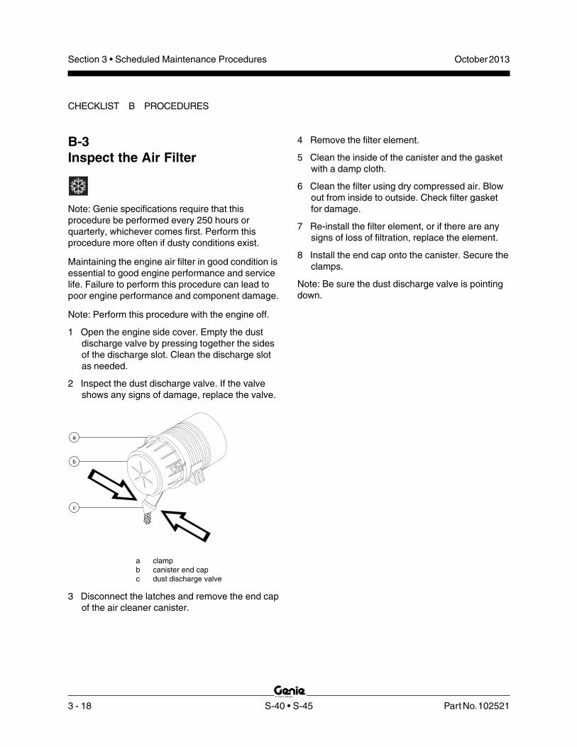
3 - 18 S-40 • S-45 Part No. 102521
October 2013Section 3 • Scheduled Maintenance Procedures
CHECKLIST B PROCEDURES
B-3Inspect the Air Filter
Note: Genie specifications require that thisprocedure be performed every 250 hours orquarterly, whichever comes first. Perform thisprocedure more often if dusty conditions exist.
Maintaining the engine air filter in good condition isessential to good engine performance and servicelife. Failure to perform this procedure can lead topoor engine performance and component damage.
Note: Perform this procedure with the engine off.
1 Open the engine side cover. Empty the dustdischarge valve by pressing together the sidesof the discharge slot. Clean the discharge slotas needed.
2 Inspect the dust discharge valve. If the valveshows any signs of damage, replace the valve.
a clampb canister end capc dust discharge valve
3 Disconnect the latches and remove the end capof the air cleaner canister.
4 Remove the filter element.
5 Clean the inside of the canister and the gasketwith a damp cloth.
6 Clean the filter using dry compressed air. Blowout from inside to outside. Check filter gasketfor damage.
7 Re-install the filter element, or if there are anysigns of loss of filtration, replace the element.
8 Install the end cap onto the canister. Secure theclamps.
Note: Be sure the dust discharge valve is pointingdown.

Part No. 102521 S-40 • S-45 3 - 19
October 2013 Section 3 • Scheduled Maintenance Procedures
B-5Perform Engine Maintenance -Deutz and Perkins Models
Engine specifications require that this procedure beperformed quarterly or every 250 hours, whichevercomes first.
Deutz models
Required maintenance procedures and additionalengine information are available in theDeutz 1011F Operation Manual(Deutz part number 0297 9683).
Deutz 1011F Operation ManualGenie part number 52883
Perkins models
Required maintenance procedures and additionalengine information are available in thePerkins 404-22 Operation Manual(Perkins part number TPD 1443S).
Perkins 404-22 Operation ManualGenie part number 94890
To access the engine:
Remove the engine tray retaining fastenerslocated under the engine tray. Loosen the pivotfastener located at the platform end of theengine tray. Swing the engine tray out andaway from the machine and secure it frommoving.
Crushing hazard. Failure to securethe engine pivot plate from movingcould result in death or seriousinjury.
B-4Test the Key SwitchGenie specifications require that this procedure beperformed every 250 hours or quarterly, whichevercomes first.
Proper key switch action and response is essentialto safe machine operation. The machine can beoperated from the ground or platform controls andthe activation of one or the other is accomplishedwith the key switch. Failure of the key switch toactivate the appropriate control panel could causea hazardous operating situation.
1 Pull out the red Emergency Stop button to theon position at both the ground and platformcontrols.
2 Turn the key switch to ground control, start theengine and then turn the key switch to platformcontrol.
3 Check all machine function from the groundcontrols.
Result: All machine functions should notoperate.
4 Turn the key switch to ground control.
5 Check all machine function from the platformcontrols.
Result: All machine functions should notoperate.
6 Turn the key switch to the off position.
Result: The engine should stop and nofunctions should operate.
CHECKLIST B PROCEDURES

3 - 20 S-40 • S-45 Part No. 102521
October 2013Section 3 • Scheduled Maintenance Procedures
CHECKLIST B PROCEDURES
B-7Check the Oil Cooler and CoolingFins - Deutz Models
Genie specifications require that this procedure beperformed every 250 hours or quarterly, whichevercomes first.
Maintaining the oil cooler in good condition isessential for good engine performance. Operatinga machine with a damaged oil cooler may result inengine damage. Also, restricting air flow throughthe oil cooler will affect the performance of thecooling system.
Bodily injury hazard. Do notinspect while the engineis running. Remove the key tosecure from operation.
Burn hazard. Beware of hotengine components. Contact withhot engine components may resultin severe burns.
Oil cooler
1 Remove the engine tray retaining fastenerslocated under the engine tray. Loosen the pivotfastener located at the platform end of theengine tray. Swing the engine tray out andaway from the machine and secure it frommoving.
Crushing hazard. Failure to securethe engine pivot plate from movingcould result in death or seriousinjury.
2 Remove the fasteners from the engine sidecover, and remove the cover.
3 Inspect the oil cooler for leaks and physicaldamage.
4 Clean the oil cooler of debris and foreignmaterial.
B-6Check the Exhaust System
Genie specifications require that this procedure beperformed every 250 hours or quarterly, whichevercomes first.
Maintaining the exhaust system is essential togood engine performance and service life. Runningthe engine with a damaged or leaking exhaustsystem can cause component damage and unsafeoperating conditions.
Bodily injury hazard. Do notinspect while the engine isrunning. Remove the key tosecure from operation.
Burn hazard. Beware of hotengine components. Contact withhot engine components may resultin severe burns.
1 Remove the engine tray retaining fastenerslocated under the engine tray. Swing the enginetray out and away from the machine and secureit from moving.
Crushing hazard. Failure to securethe engine pivot plate from movingcould result in death or seriousinjury.
2 Be sure that all nuts and bolts are tight.
3 Inspect all welds for cracks.
4 Inspect for exhaust leaks; i.e., carbon builduparound seams and joints.
5 Swing the engine back to its original positionand install the engine pivot plate retainingfasteners.
Crushing hazard. Failure to installthe fasteners into the engine trayto secure it from moving couldresult in death or serious injury.

Part No. 102521 S-40 • S-45 3 - 21
October 2013 Section 3 • Scheduled Maintenance Procedures
B-8Inspect the Tires, Wheelsand Lug Nut Torque
Genie specifications require that this procedure beperformed every 250 hours or quarterly, whichevercomes first.
Maintaining the tires and wheels in goodcondition including proper wheel fastener torque isessential to safe operation and good performance.Tire and/or wheel failure could result in a machinetip-over. Component damage may also result ifproblems are not discovered and repaired in atimely fashion.
Bodily injury hazard. An over-inflated tire can explode and couldcause death or serious injury.
Tip-over hazard. Do not usetemporary flat tire repair products.
Note: The tires on some machines are foam-filledand do not need air added to them.
1 Check all tire treads and sidewalls for cuts,cracks, punctures and unusual wear.
2 Check each wheel for damage, bends andcracks.
3 Check each lug nut for proper torque. Refer toSection 2, Specifications.
Models with air-filled tires:
4 Check pressure in each air-filled tire. Add air asnecessary. Refer to Section 2, Specifications.
a oil coolerb cylinder head cooling finsc fan blower fins
Cooling and fan blower fins
5 Inspect the fan blower fins for physical damage.
6 Clean the fan blower fins of debris and foreignmaterial.
7 Inspect the head cooling passages and fins forphysical damage or foreign material, using aflashlight.
8 Clean the cylinder head cooling passages ofdebris and foreign material.
9 Install the engine side cover.
10 Swing the engine back to its original positionand install the engine pivot plate retainingfasteners. Tighten the pivot fastener.
Crushing hazard. Failure to installthe fasteners into the engine trayto secure it from moving couldresult in death or serious injury.
cba
CHECKLIST B PROCEDURES

3 - 22 S-40 • S-45 Part No. 102521
October 2013Section 3 • Scheduled Maintenance Procedures
CHECKLIST B PROCEDURES
Turntable rotate drive hub
1 Remove the plug located on the side of the huband check the oil level.
Result: The oil level should be even with thebottom of the plug hole.
turntable drive huba plug
2 If necessary, add oil until the oil level is evenwith the bottom of the plug hole.
3 Apply pipe thread sealant to the plug, andinstall the plug in the drive hub.
4 Check the torque of the turntable drive hubmounting fasteners. Refer to Section 2,Specifications.
a
B-9Check the Drive Hub Oil Leveland Fastener Torque
Genie specifications require that this procedure beperformed every 250 hours or quarterly, whichevercomes first.
Failure to maintain proper drive hub oil levels maycause the machine to perform poorly andcontinued use may cause component damage.
1 Drive the machine to rotate the hub until theplugs are located one on top and the otherat 90 degrees.
2 Remove the plug located at 90 degrees andcheck the oil level.
Result: The oil level should be even with thebottom of the side plug hole.
3 If necessary, remove the top plug and add oiluntil the oil level is even with the bottom of theside plug hole. Refer to Section 2,Specifications.
4 Install the plug(s) in the drive hub. Use pipethread sealant on units with pipe plugs.
5 Check the torque of the drive hub mountingfasteners. Refer to Section 2, Specifications.
6 Repeat this procedure for each drive hub.
models with pipe plugs a drive hub plugs
a
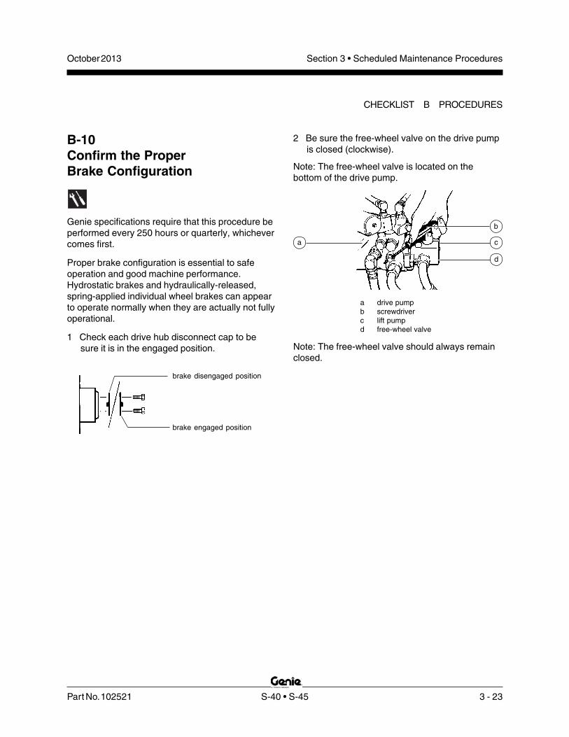
Part No. 102521 S-40 • S-45 3 - 23
October 2013 Section 3 • Scheduled Maintenance Procedures
brake disengaged position
brake engaged position
B-10Confirm the ProperBrake Configuration
Genie specifications require that this procedure beperformed every 250 hours or quarterly, whichevercomes first.
Proper brake configuration is essential to safeoperation and good machine performance.Hydrostatic brakes and hydraulically-released,spring-applied individual wheel brakes can appearto operate normally when they are actually not fullyoperational.
1 Check each drive hub disconnect cap to besure it is in the engaged position.
2 Be sure the free-wheel valve on the drive pumpis closed (clockwise).
Note: The free-wheel valve is located on thebottom of the drive pump.
a drive pumpb screwdriverc lift pumpd free-wheel valve
Note: The free-wheel valve should always remainclosed.
a
d
c
b
CHECKLIST B PROCEDURES

3 - 24 S-40 • S-45 Part No. 102521
October 2013Section 3 • Scheduled Maintenance Procedures
CHECKLIST B PROCEDURES
a solenoid bootb high idle adjustment nutc yoke lock nutd yokee low idle adjustment screwf low idle lock nut
If high idle rpm is correct, disregardadjustment step 4.
4 Loosen the yoke lock nut. Turn the high idleadjustment nut and solenoid bootcounterclockwise to increase the rpm orclockwise to decrease the rpm. Tighten theyoke lock nut and re-check the rpm.
Note: Be sure the solenoid fully retracts whenactivating high idle.
Perkins Models
1 Connect a tachometer to the engine. Start theengine from the ground controls. Refer toSection 2, Specifications.
B-11Check and Adjust theEngine RPM
Genie specifications require that this procedure beperformed every 250 hours or quarterly, whichevercomes first.
Maintaining the engine rpm at the proper setting forboth low and high idle is essential to good engineperformance and service life. The machine will notoperate properly if the rpm is incorrect andcontinued use may cause component damage.
Note: This procedure will require two people.
Ford Models
Note: The engine rpm is controlled by the ECMand can only be adjusted by re-programming theECM. If rpm adjustment or service is required,please contact Genie Industries ServiceDepartment OR your local Ford dealer.
Deutz Models
1 Connect a tachometer to the engine. Start theengine from the ground controls. Refer toSection 2, Specifications.
Skip to step 3 if the low idle rpm is correct.
2 Loosen the low idle lock nut and turn the lowidle adjustment screw clockwise to increase therpm or counterclockwise to decrease the rpm.Tighten the low idle lock nut and re-check therpm.
3 Move the function enable/rpm select toggleswitch to the high idle (rabbit symbol) positionat the ground controls. Refer to Section 2,Specifications.
f
e
c dba
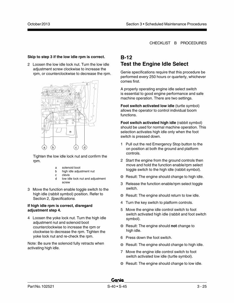
Part No. 102521 S-40 • S-45 3 - 25
October 2013 Section 3 • Scheduled Maintenance Procedures
a b c d
B-12Test the Engine Idle SelectGenie specifications require that this procedure beperformed every 250 hours or quarterly, whichevercomes first.
A properly operating engine idle select switchis essential to good engine performance and safemachine operation. There are two settings.
Foot switch activated low idle (turtle symbol)allows the operator to control individual boomfunctions.
Foot switch activated high idle (rabbit symbol)should be used for normal machine operation. Thisselection activates high idle only when the footswitch is pressed down.
1 Pull out the red Emergency Stop button to theon position at both the ground and platformcontrols.
2 Start the engine from the ground controls thenmove and hold the function enable/rpm selecttoggle switch to the high idle (rabbit symbol).
Result: The engine should change to high idle.
3 Release the function enable/rpm select toggleswitch.
Result: The engine should return to low idle.
4 Turn the key switch to platform controls.
5 Move the engine idle control switch to footswitch activated high idle (rabbit and foot switchsymbol).
Result: The engine should not change tohigh idle.
6 Press down the foot switch.
Result: The engine should change to high idle.
7 Move the engine idle control switch to footswitch activated low idle (turtle symbol).
Result: The engine should change to low idle.
Skip to step 3 if the low idle rpm is correct.
2 Loosen the low idle lock nut. Turn the low idleadjustment screw clockwise to increase therpm, or counterclockwise to decrease the rpm.
Tighten the low idle lock nut and confirm therpm.
a solenoid bootb high idle adjustment nutc clevisd low idle lock nut and adjustment
screw
3 Move the function enable toggle switch to thehigh idle (rabbit symbol) position. Refer toSection 2, Specifications.
If high idle rpm is correct, disregardadjustment step 4.
4 Loosen the yoke lock nut. Turn the high idleadjustment nut and solenoid bootcounterclockwise to increase the rpm orclockwise to decrease the rpm. Tighten theyoke lock nut and re-check the rpm.
Note: Be sure the solenoid fully retracts whenactivating high idle.
CHECKLIST B PROCEDURES

3 - 26 S-40 • S-45 Part No. 102521
October 2013Section 3 • Scheduled Maintenance Procedures
CHECKLIST B PROCEDURES
2 Start the engine from the platform controls andallow it to run at low idle. Press down the footswitch to allow the engine to run at high idle.
Result: The engine should start promptly andoperate smoothly in low and high idle.
3 Release the foot switch and shut the engine offby pushing the red Emergency Stop buttonin to the off position.
4 Move the fuel select switch to LPG.
5 Start the engine and allow it to run atlow idle. Press down the foot switch to allow theengine to run at high idle.
Result: The engine should start promptly andoperate smoothly in low and high idle.
Note: The engine may hesitate momentarily andthen continueto run on the selected fuel if switched whilerunning.
B-13Test the Fuel Select Operation -Ford Models
Genie specifications require that this procedure beperformed every 250 hours or quarterly, whichevercomes first.
The ability to select and switch betweengasoline and LPG fuels as needed is essential tosafe machine operation. A fuel selection can bemade when the engine is running or not.Switching malfunctions and/or the failure of theengine to start and run properly in both fuelmodes and through all idle speeds can indicatefuel system problems that could develop into ahazardous situation.
Note: Perform this test after checking the gasolineand LPG fuel levels, and warming the engine tonormal operating temperature.
1 Move the fuel select switch to gasoline and thenmove the engine idle control switch to footswitch activated high idle (rabbit and foot switchsymbol).

Part No. 102521 S-40 • S-45 3 - 27
October 2013 Section 3 • Scheduled Maintenance Procedures
B-14Test the Ground Control OverrideGenie specifications require that this procedure beperformed every 250 hours or quarterly, whichevercomes first.
A properly functioning ground control override isessential to safe machine operation. The groundcontrol override function is intended to allowground personnel to operate the machine from theground controls whether or not the red EmergencyStop button on the platform controls is in the on oroff position. This function is particularly useful if theoperator at the platform controls cannot return theboom to the stowed position.
1 Push in the platform red Emergency Stopbutton to the off position.
2 Start the engine from the ground controls.
3 At the ground controls, operate each boomfunction through a partial cycle.
Result: All boom functions should operate.
B-15Check the Directional ValveLinkage
Genie specifications require that this procedure beperformed every 250 hours or quarterly, whichevercomes first.
Note: Perform this test only on models equippedwith a oscillating axle.
Proper axle oscillation is essential to safe machineoperation. If the directional valve linkage is notoperating correctly, the stability of the machine iscompromised and it may tip over.
1 Remove the drive chassis cover and the axlecovers from the non-steer end of the drivechassis.
2 Locate the directional valve inside of the non-steer axle and inspect the linkage for thefollowing:
• Lock nut is tight against yoke
• Yoke clevis pins are installed
• Cotter pins are installed through clevispins
• Linkage is properly attached todirectional valve
CHECKLIST B PROCEDURES
3 - 28 S-40 • S-45 Part No. 102521
October 2013Section 3 • Scheduled Maintenance Procedures
CHECKLIST B PROCEDURES
B-17Test the Drive Brakes
Genie specifications require that this procedure beperformed every 250 hours or quarterly, whichevercomes first.
Proper brake action is essential to safe machineoperation. The drive brake function should operatesmoothly, free of hesitation, jerking and unusualnoise. Hydrostatic brakes and hydraulically-released individual wheel brakes can appear tooperate normally when they are actually not fullyoperational.
Collision hazard. Be sure that themachine is not in free-wheel orpartial free-wheel configuration.See B-10, Confirm the ProperBrake Configuration.
Note: Select a test area that is firm, level and freeof obstructions.
1 Mark a test line on the ground for reference.
2 Start the engine from the platform controls.
3 Move the engine idle control switch tofoot switch activated high idle (rabbit andfoot switch symbol), then lower the boom intothe stowed position.
4 Choose a point on the machine; i.e., contactpatch of a tire, as a visual reference for usewhen crossing the test line.
5 Bring the machine to top drive speed beforereaching the test line. Release the drive joystickwhen your reference point on the machinecrosses the test line.
6 Measure the distance between the test line andyour machine reference point. Refer toSection 2, Specifications.
Note: The brakes must be able to hold the machineon any slope it is able to climb.
B-16Test the Platform Self-leveling
Genie specifications require that this procedure beperformed every 250 hours or quarterly, whichevercomes first.
Automatic platform self-leveling throughoutthe full cycle of primary boom raising and loweringis essential for safe machine operation. Theplatform is maintained at level by the platformleveling slave cylinder which operates in a closedloop hydraulic circuit with the master cylinderlocated at the base of the boom.
A platform self-leveling failure creates an unsafeworking condition for platform and groundpersonnel.
1 Start the engine from the ground controls andlower the boom to the stowed position.
2 Hold the function enable toggle switch to eitherside and adjust the platform to a level positionusing the platform level toggle switch.
3 Raise and lower the primary boom through a fullcycle.
Result: The platform should remain level atall times to within ±5 degrees.

Part No. 102521 S-40 • S-45 3 - 29
October 2013 Section 3 • Scheduled Maintenance Procedures
B-19Test the Drive Speed -Raised or Extended Position
Genie specifications require that this procedure beperformed every 250 hours or quarterly, whichevercomes first.
Proper drive function movement is essential tosafe machine operation. The drive function shouldrespond quickly and smoothly to operator control.Drive performance should also be free ofhesitation, jerking and unusual noise over theentire proportionally controlled speed range.
Note: Select a test area that is firm, level and freeof obstructions.
1 Create start and finish lines by marking twolines on the ground 40 feet / 12.2 m apart.
2 Start the engine from the platform controls.
3 Move the engine idle select switch to foot switchactivated high idle (rabbit and foot switchsymbol).
4 Raise the boom above horizontal.
5 Choose a point on the machine; i.e., contactpatch of a tire, as a visual reference for usewhen crossing the start and finish lines.
B-18Test the Drive Speed -Stowed Position
Genie specifications require that this procedure beperformed every 250 hours or quarterly, whichevercomes first.
Proper drive function movement is essential tosafe machine operation. The drive function shouldrespond quickly and smoothly to operator control.Drive performance should also be free ofhesitation, jerking and unusual noise over theentire proportionally controlled speed range.
Note: Select a test area that is firm, level and freeof obstructions.
1 Create start and finish lines by marking twolines on the ground 40 feet / 12.2 m apart.
2 Start the engine from the platform controls.
3 Move the engine idle control switch tofoot switch activated high idle (rabbit and footswitch symbol), then lower the boom into thestowed position.
4 Choose a point on the machine; i.e., contactpatch of a tire, as a visual reference for usewhen crossing the start and finish lines.
5 Bring the machine to top drive speed beforereaching the start line. Begin timing when yourreference point on the machine crosses thestart line.
6 Continue at full speed and note the time whenthe machine reference point crosses the finishline. Refer to Section 2, Specifications.
CHECKLIST B PROCEDURES

3 - 30 S-40 • S-45 Part No. 102521
October 2013Section 3 • Scheduled Maintenance Procedures
CHECKLIST B PROCEDURES
B-20Perform Hydraulic Oil Analysis
Genie specifications require that this procedure beperformed every 250 hours or quarterly, whichevercomes first.
Replacement or testing of the hydraulic oil isessential for good machine performance andservice life. Dirty oil and a clogged suction strainermay cause the machine to perform poorly andcontinued use may cause component damage.Extremely dirty conditions may require oil changesto be performed more often.
Note: Before replacing the hydraulic oil, the oil maybe tested by an oil distributor for specific levels ofcontamination to verify that changing the oil isnecessary. If the hydraulic oil is not replaced atthe two year inspection, test the oil quarterly.Replace the oil when it fails the test.See E-1, Test or Replace the Hydraulic Oil.
6 Bring the machine to top drive speed beforereaching the start line. Begin timing when yourreference point on the machine crosses thestart line.
7 Continue at full speed and note the time whenthe machine reference point crosses the finishline. Refer to Section 2, Specifications.
8 Lower the boom to the stowed position andextend the boom 1 foot / 30 cm.
9 Choose a point on the machine; i.e., contactpatch of a tire, as a visual reference for usewhen crossing the start and finish lines.
10 Bring the machine to top drive speed beforereaching the start line. Begin timing when yourreference point on the machine crosses thestart line.
11 Continue at top speed and note the time whenthe machine reference point crosses the finishline. Refer to Section 2, Specifications.

Part No. 102521 S-40 • S-45 3 - 31
October 2013 Section 3 • Scheduled Maintenance Procedures
3 Move the function enable/rpm select toggleswitch to either side and activate the jib boomtoggle switch in the down position, hold for amoment and then release it.
Result: The descent alarm should sound whenthe toggle switch is held down.
4 Turn the key switch to platform controls.
Result: The flashing beacons should be onand flashing.
5 Press down the foot switch. Move the boomcontroller to the down position, hold for amoment and then release it.
Result: The descent alarm should sound whenthe controller is held down.
6 Press down the foot switch. Move the jib boomtoggle switch to the down position, hold for amoment and then release it.
Result: The descent alarm should sound whenthe controller is held down.
7 Press down the foot switch. Move the drivecontroller off center, hold for a moment andthen release it. Move the drive controller offcenter in the opposite direction, hold for amoment and then release it.
Result: The travel alarm should sound when thedrive controller is moved off center in eitherdirection.
B-21Test the Alarm Package(if equipped) and theDescent AlarmGenie specifications require that this procedure beperformed every 250 hours or quarterly, whichevercomes first.
The alarm package includes:
• Travel alarm
• Flashing beacons
Alarms and beacons are installed to alert operatorsand ground personnel of machine proximity andmotion. The alarm package is installed on theturntable rear cover. Beacons are installed on bothturntable covers.
Note: The alarms and beacons will operate withthe engine running or not running.
Note: The descent alarm is standard equipmentbeginning with serial number 12602.
1 Turn the key switch to ground controls and pullout the red Emergency Stop button to the onposition at both the ground and platformcontrols.
Result: Both flashing beacons should be on andflashing.
2 Hold the function enable switch to either sideand activate the boom toggle switch in thedown position, hold for a moment and thenrelease it.
Result: The descent alarm should sound whenthe toggle switch is held down.
CHECKLIST B PROCEDURES

3 - 32 S-40 • S-45 Part No. 102521
October 2013Section 3 • Scheduled Maintenance Procedures
CHECKLIST B PROCEDURES
2 Check for proper venting.
Note: When checking for positive fuel tank capventing, air should pass freely through the cap.
Result: Air should pass through the fuel tankcap. Proceed to step 4.
Result: Air is not passing through the fuel tankcap. Clean or replace the cap.Proceed to step 3.
3 Using a mild solvent, carefully wash the capventing system. Dry using low pressurecompressed air. Repeat this procedurebeginning with step 2.
4 Install the fuel tank cap onto the fuel tank.
All models:
5 Remove the breather cap from the hydraulictank.
6 Check for proper venting.
Result: Air should pass through the breathercap. Proceed to step 8.
Result: If air does not pass through the breathercap, clean or replace the cap.Proceed to step 7.
Note: When checking for positive tank cap venting,air should pass freely through the cap.
7 Using a mild solvent, carefully wash the capventing system. Dry using low pressurecompressed air. Repeat this procedurebeginning with step 6.
8 Install the breather cap onto the hydraulic tank.
B-22Inspect the Fuel and HydraulicTank Cap Venting Systems
Genie specifications require that this procedure beperformed quarterly or every 250 hours, whichevercomes first. Perform this procedure more often ifdusty conditions exist.
A free-breathing fuel and hydraulic tank cap isessential for good machine performance andservice life. A dirty or clogged cap may cause themachine to perform poorly and continued use maycause component damage. Extremely dirtyconditions may require that the cap be inspectedmore often.
Explosion and fire hazard. Enginefuels are combustible. Perform thisprocedure in an open, well-ventilated area away from heaters,sparks, flames and lightedtobacco. Always have anapproved fire extinguisher withineasy reach.
Gasoline/LPG models (before serialnumber 13740) and Diesel models (all):
Note: Perform this procedure with the engine off.
Note: Gasoline/LPG models use a pressurized capbeginning with serial number 13740.
1 Remove the cap from the fuel tank.

Part No. 102521 S-40 • S-45 3 - 33
October 2013 Section 3 • Scheduled Maintenance Procedures
5 Visually inspect the section of track under thebogey wheels.
Result: There should be between 0.75 - 1 inch /1.9 - 2.5 cm of gap between the bogey wheelsand the inside surface of the track. Proceed tostep 7.
Result: There is 1 inch / 2.5 cm or more of gapbetween the bogey wheels and the insidesurface of the track. Proceed to step 6.
bogey wheeltensioner
assembly
idler wheel
half sprocket
B-23Check the Track Tension andFastener Torque, TRAX option
Note: Manufacturer specifications require that thisprocedure be performed every 250 hours orquarterly.
Maintaining proper track tension and properlytorqued fasteners is essential to good machineperformance and service life. The machine will notoperate properly with a track that is incorrectlytensioned. Continued use of a machine withincorrectly tensioned tracks may cause componentdamage.
1 Thoroughly clean the track assembly of any dirt,rocks, clay, etc.
2 Chock the tracks at one end of the machine toprevent the machine from rolling.
3 Center a lifting jack of ample capacity(20,000 lbs / 10,000 kg) under the drive chassisbetween the tracks at the other end of themachine.
4 Lift the machine until the tracks are off theground and then place jack stands under thedrive chassis for support.
CHECKLIST B PROCEDURES

3 - 34 S-40 • S-45 Part No. 102521
October 2013Section 3 • Scheduled Maintenance Procedures
B-24Perform Engine Maintenance -Ford Models
Engine specifications require that this procedure beperformed every 400 hours.
Proper engine maintenance, following the enginemanufacturer's maintenance schedule, is essentialto good engine performance and service life.Failure to perform the maintenance procedurescan lead to poor engine performance andcomponent damage.
Required maintenance procedures and additionalengine information are available in theFord LRG-425 EFI Operator Handbook(Ford part number FPP 194-302) or theFFord DSG-423 EFI Operator Handbook(EDI part number 1060020) or theFord MSG-425 EFI Operator Handbook(Ford part number 1020010) .
Ford LRG 425 EFI Operation ManualGenie part number 84792
Ford DSG 423 EFI Operator HandbookGenie part number 119488
Ford MSG-425 EFI Operator HandbookGenie part number 215322
To access the engine:
Remove the engine tray retaining fastenerslocated under the engine tray. Loosen the pivotfastener located at the platform end of theengine tray. Swing the engine tray out andaway from the machine and secure it frommoving.
Crushing hazard. Failure to securethe engine pivot plate from movingcould result in death or seriousinjury.
6 Loosen the tensioner jam nut and idler axle boltson both sides of the tensioner wheel and tightenthe tensioner nut until there is between 0.75 - 1inch /1.9 - 2.5 cm of gap between the bogey wheelsand the inside surface of the track.
Component damage hazard.Do not over tighten the track.Overtightening the track will causethe machine to lose power duringoperation.
7 Tighten the jam nut.
8 Check the torque of the track assemblyfasteners. Refer to Section 2, Specifications.
9 Raise the machine, remove the jack stands andlower the machine.
10 Repeat this procedure for each track assembly.
CHECKLIST B PROCEDURES

Part No. 102521 S-40 • S-45 3 - 35
October 2013 Section 3 • Scheduled Maintenance Procedures
Checklist C Procedures
C-1Perform Engine Maintenance -Deutz and Perkins Models
Engine specifications require that this procedure beperformed every 500 hours.
Proper engine maintenance, following the enginemanufacturer's maintenance schedule, is essentialto good engine performance and service life.Failure to perform the maintenance procedurescan lead to poor engine performance andcomponent damage.
Deutz models
Required maintenance procedures and additionalengine information are available in theDeutz 1011F Operation Manual(Deutz part number 0297 9683) or theDeutz 2011 Operation Manual(Deutz part number 0312 3547).
Deutz 1011F Operation ManualGenie part number 52883
Deutz 2011 Operation ManualGenie part number 139320
Perkins models
Required maintenance procedures and additionalengine information are available in thePerkins 404-22 Operation Manual(Perkins part number TPD 1443S).
Perkins 404-22 Operation ManualGenie part number 94890
To access the engine:
Remove the engine tray retaining fastenerslocated under the engine tray. Loosen the pivotfastener located at the platform end of theengine tray. Swing the engine tray out andaway from the machine and secure it frommoving.
Crushing hazard. Failure to securethe engine pivot plate from movingcould result in death or seriousinjury.

3 - 36 S-40 • S-45 Part No. 102521
October 2013Section 3 • Scheduled Maintenance Procedures
CHECKLIST C PROCEDURES
C-2Grease the Platform OverloadMechanism (if equipped)
Genie specifications require that this procedure beperformed every 500 hours or 6 months, whichevercomes first. Perform this procedure more often ifdusty conditions exist.
Application of lubrication to the platform overloadmechanism is essential to safe machine operation.Continued use of an improperly greased platformoverload mechanism could result in the system notsensing an overloaded platform condition and willresult in component damage.
1 Locate the grease fittings on each pivot pin ofthe platform overload assembly.
2 Thoroughly pump grease into each greasefitting using a multi-purpose grease.
Grease type
Chevron Ultra-duty grease, EP NLGI 2 (lithium based)or equivalent
C-3Test the Platform OverloadSystem (if equipped)
Genie specifications require that this procedure beperformed every 500 hours or six months,whichever comes first.
Testing the platform overload system regularly isessential to safe machine operation. Continued useof an improperly operating platform overloadsystem could result in the system not sensing anoverloaded platform condition. Machine stablitycould be compromised resulting in the machinetipping over.
Note: Perform this procedure with the machine on afirm, level surface.
1 Turn the key switch to platform control. Start theengine and level the platform.
2 Determine the maximum platform capacity.Refer to the machine serial plate.
3 Remove all weight, tools and accessories fromthe platform.
Note: Failure to remove all weight, tools andaccessories from the platform will result in aninaccurate test.
4 Using a suitable lifting device, place a testweight equal to that of the available capacity atone of the locations shown.Refer to Illustration 1.
Result: The platform overload indicator lightsshould be off at both the ground and platformcontrols and the alarm should not sound.
Result: The platform overload indicator lights areon and the alarm is sounding. Calibrate theplatform overload system. Refer to RepairProcedure 2-4, How to Calibrate the PlatformOverload System (if equipped).

Part No. 102521 S-40 • S-45 3 - 37
October 2013 Section 3 • Scheduled Maintenance Procedures
CHECKLIST C PROCEDURES
7 Using a suitable lifting device, remove the testweights, restart the engine and carefully movethe test weights to each remaining location onthe platform. Refer to Illustration 1.
Result: The alarm should sound, the engineshould shut off and the platform overloadindicator lights should be flashing at both theground and platform controls.
Result: The alarm does not sound and theplatform overload indicator lights are notflashing. Calibrate the platform overloadsystem. Refer to Repair Procedure 2-4, How toCalibrate the Platform Overload System (ifequipped).
Note: There may be a 2 second delay before theoverload indicator lights flash, the alarm soundsand the engine shuts off.
8 Test all machine functions from the platformcontrols.
Result: All platform control functions should notoperate.
9 Turn the key switch to ground control.
10 Test all machine functions from the groundcontrols.
Result: All ground control functions should notoperate.
11 Activate the auxiliary power toggle switch.
12 Using auxiliary power, test all machine functionsfrom the ground controls.
Result: All ground control functions shouldoperate.
13 Using a suitable lifting device, lift the additionaltest weight from the platform.
Result: The platform overload indicator lightsshould turn off at both the ground and platformcontrols and the alarm should not sound.
Illustration 1
5 Carefully move the test weight to eachremaining location. Refer to Illustration 1.
Result: The platform overload indicator lightsshould be off at both the ground and platformcontrols and the alarm should not sound.
Result: The platform overload indicator lights areon and the alarm is sounding. Calibrate theplatform overload system. Refer to RepairProcedure 2-4, How to Calibrate the PlatformOverload System (if equipped).
6 Using a suitable lifting device, place anadditional 50 lbs / 23 kg of weight onto theplatform.
Result: The alarm should sound and the engineshould shut off. The platform overload indicatorlights should be flashing at both the ground andplatform controls.
Result: The alarm does not sound, the enginedoes not shut off and the platform overloadindicator lights are not flashing. Calibrate theplatform overload system. Refer to RepairProcedure 2-4, How to Calibrate the PlatformOverload System (if equipped).
Note: There may be a 2 second delay before theoverload indicator lights flash, the alarm soundsand the engine shuts off.

3 - 38 S-40 • S-45 Part No. 102521
October 2013Section 3 • Scheduled Maintenance Procedures
CHECKLIST C PROCEDURES
14 Start the engine and test all machine functionsfrom the ground controls.
Result: All ground control functions shouldoperate normally.
15 Turn the key switch to platform control.
16 Test all machine functions from the platformcontrols.
Result: All platform control functions shouldoperate.
Note: If the platform overload system is notoperating properly, Refer to Repair Procedure 2-4,How to Calibrate the Platform Overload System (ifequipped).
17 Push in the red Emergency stop button at theplatform to shut off engine.
18 Using a suitable lifting device, remove all testweights from the platform.
19 Pull out the red Emergency stop button to the onposition at the platform controls.
20 Remove the fasteners securing the lid to theplatform controls. Using Illustration 2 as aguide, locate the timer relay inside the platformcontrol box. Tag and disconnect the red wirefrom terminal 5 on the timer relay.
Illustration 2
Timer Relay
OrangeWire
Terminal 5
21 Using Illustration 3 as a guide, locate D31 ValvePower LED on the ALC500 printed circuit board.
Illustration 3
22 Step on the footswitch at the platform.
Result: The Valve Power LED should notilluminate.
Result: The Valve Power LED is illuminated.Remove the machine from service and contactthe Genie Service Department.
23 Securely install the red wire, disconnected instep 20, onto terminal 5 of the relay timer.
24 Step on the footswitch at the platform.
Result: The Valve Power LED should illuminate.
Result: The Valve Power LED is not illuminated.Remove the machine from service and contactthe Genie Service Department.
25 Using a suitable lifting device, place a testweight equal to that of the available capacity atthe center location shown in Illustration 1.
Valve Power LED
ALC 500 Board

Part No. 102521 S-40 • S-45 3 - 39
October 2013 Section 3 • Scheduled Maintenance Procedures
C-4Replace the Engine Air FilterElement - Deutz and PerkinsModels
Genie specifications requires that this procedurebe performed every 500 hours or 6 months,whichever comes first.
Maintaining the engine air filter in good condition isessential to good engine performance and servicelife. Failure to perform this procedure can lead topoor engine performance and component damage.
1 Open the evacuator valve located on the aircleaner cap by squeezing the sides togetherwith your fingers.
2 Disconnect the latches on the air cleaner cap.Remove the end cap from the air cleanercanister.
3 Remove the filter element.
4 Clean the inside of the canister and the gasketwith a damp cloth.
5 Install the new filter element.
6 Install the end cap on the canister and re-connect the latches.
Note: Be sure the evacuator valve is pointingdown.
CHECKLIST C PROCEDURES
26 Using a suitable lifting device, place anadditional 50 lbs / 23 kg of weight onto theplatform.
Result: The alarm should sound and the ValvePower LED should not light. The platformoverload indicator lights should be flashing atboth the ground and platform controls.
27 Working from outside the platform and standingnext to the platform rotator, locate the orangewire, which enters into the base of the platformcontrol box from the load sense switch andlocate the wire terminal at the end of the wire.Tag and disconnect the connectors.Refer to Illustration 2.
28 Using a multimeter set to read resistance(ohms), securely install a lead from themultimeter to the connector on the orange wire,and securely connect the other multimeter leadto a ground point in the control box.
Result: The readout on the multimeter shouldindicate zero resistance.
Result: The readout on the multimeter showsresistance. Remove the machine from serviceand contact the Genie Service Department.
29 Using a suitable lifting device, remove all weightfrom the platform. Note the result on themultimeter.
Result: The readout on the multimeter shouldindicate infinite resistance.
Result: The readout on the multimeter showszero resistance. Remove the machine fromservice and contact the Genie ServiceDepartment.
31 Turn off the multimeter and remove the leadsfrom the machine. Securely connect the wiresdisconnected in step 27.
32 Close the platform control box. Install andsecurely tighten the fasteners. Do notovertighten.

3 - 40 S-40 • S-45 Part No. 102521
October 2013Section 3 • Scheduled Maintenance Procedures
C-6Perform Engine Maintenance -Ford Models
Engine specifications require that this procedure beperformed every 800 hours.
Proper engine maintenance, following the enginemanufacturer's maintenance schedule, is essentialto good engine performance and service life.Failure to perform the maintenance procedurescan lead to poor engine performance andcomponent damage.
Required maintenance procedures and additionalengine information are available in theFord LRG-425 EFI Operator Handbook(Ford part number FPP 194-302) OR theFord DSG-423 EFI Operator Handbook(EDI part number 1060020) or theFord MSG-425 EFI Operator Handbook(Ford part number 1020010) .
Ford LRG 425 EFI Operation ManualGenie part number 84792
Ford DSG 423 EFI Operator HandbookGenie part number 119488
Ford MSG-425 EFI Operator HandbookGenie part number 215322
To access the engine:
Remove the engine tray retaining fastenerslocated under the engine tray. Loosen the pivotfastener located at the platform end of theengine tray. Swing the engine tray out andaway from the machine and secure it frommoving.
Crushing hazard. Failure to securethe engine pivot plate from movingcould result in death or seriousinjury.
CHECKLIST C PROCEDURES
C-5Replace the In-line Fuel Strainer -Deutz Models
Engine specifications require that this procedurebe performed every 500 hours or 6 months,whichever comes first.
Replacing the diesel fuel strainer is essential forgood engine performance and service life. A dirtyor clogged filter may cause the engine to performpoorly and continued use may cause componentdamage.
Explosion and fire hazard. Enginefuels are combustible. Perform thisprocedure in an open, well-ventilated area away from heaters,sparks, flames and lightedtobacco. Always have anapproved fire extinguisher withineasy reach.
Note: Perform this procedure with the engine off.
1 Put on protective clothing and eye wear.
2 Locate the inline strainer above the throttleactuator solenoid.
4 Place a suitable container under the filter.
5 Loosen the clamp holding the strainer to theengine mount. Loosen the clamps securing thefuel lines to the strainer. Remove and replace.

Part No. 102521 S-40 • S-45 3 - 41
October 2013 Section 3 • Scheduled Maintenance Procedures
D-1Check the Boom Wear Pads
Genie specifications requires that this procedurebe performed every 1000 hours or annually,whichever comes first.
Maintaining the boom wear pads in good conditionis essential to safe machine operation. Wear padsare placed on boom tube surfaces to provide a lowfriction, replaceable wear pad between movingparts. Improperly shimmed wear pads or continueduse of extremely worn wear pads may result incomponent damage and unsafe operatingconditions.
1 Start the engine from the ground controls.
2 Raise the end of the primary boom to acomfortable working height (chest high), thenextend the boom 1 foot / 30 cm.
3 Measure each wear pad. Replace the wear padonce it reaches the minimum allowablethickness. If the wear pad is still withinspecification, shim as necessary to obtainminimum clearance with zero binding.
Note: The minimum shim clearance for primaryboom wear pads is 0.070 inch / 1.8 mm and themaximum allowable shim clearance is 0.188 inch /4.8 mm.
Wear padspecifications Minimum
all wear pads 9/16 inch14.3 mm
4 Extend and retract the boom through the entirerange of motion to check for tight spots thatmay cause binding or scraping of the boom.
Note: Always maintain squareness between theouter and inner boom tubes.
Checklist D Procedures

3 - 42 S-40 • S-45 Part No. 102521
October 2013Section 3 • Scheduled Maintenance Procedures
CHECKLIST D PROCEDURES
1
713
16
10
4
2
8 14
1711
20 5
3
9
15
18
19
12
6
Bolt torque sequence
4 Be sure that each turntable mounting bolt istorqued in sequence to specifications. Refer toSection 2, Specifications.
5 Start the engine form the ground controls.
6 Raise the secondary boom and remove thesafety chock.
7 Lower the boom to the stowed position.
8 Remove drive chassis covers from both thesteer end and the non-steer end of themachine.
D-2
Check the Turntable RotationBearing Bolts
Genie specifications requires that this procedurebe performed every 1000 hours or annually,whichever comes first.
Maintaining proper torque on the turntable bearingbolts is essential to safe machine operation.Improper bolt torque could result in an unsafeoperating condition and component damage.
1 Raise the primary boom and place safetychocks on the lift cylinders rods. Carefully lowerthe boom onto the lift cylinders safety chocks.
Crushing hazard. Keep handsaway from cylinders and allmoving parts when lowering theboom.
Note: The lift cylinder safety chock is availablethrough Genie (Genie part number 75097).
2 Turn the engine off.
3 Remove the engine tray retaining fastenerslocated under the engine tray. Swing the enginetray out and away from the machine and secureit from moving.
Crushing hazard. Failure to securethe engine pivot plate from movingcould result in death or seriousinjury.

Part No. 102521 S-40 • S-45 3 - 43
October 2013 Section 3 • Scheduled Maintenance Procedures
1
713
16
10
4
2
8 14
1711
20 5
3
9
15
18
19
12
6
9 Check to ensure that each lower bearingmounting bolt under the drive chassis istorqued in sequence to specifications. Refer toSection 2, Specifications.
Bolt torque sequence
10 Swing the engine back to its original positionand install the engine pivot plate retainingfasteners.
Crushing hazard. Failure to installthe fasteners into the engine trayto secure it from moving couldresult in death or serious injury.
disengaged position
engaged position
D-3
Check the Free-wheelConfiguration
Genie specifications requires that this procedurebe performed every 1000 hours or annually,whichever comes first.
Proper use of the free-wheel configuration isessential to safe machine operation. Thefree-wheel configuration is used primarily fortowing. A machine configured to free-wheel withoutoperator knowledge may cause death or seriousinjury and property damage.
Collision hazard. Select a worksite that is firm and level.
Component damage hazard. If themachine must be towed, do notexceed 2 mph / 3.2 km/h.
Non-steer Wheels: All Models
1 Chock the steer wheels to prevent the machinefrom rolling.
2 Center a lifting jack of sufficient capacity(20,000 lbs / 10,000 kg) under the drive chassisbetween the non-steer tires.
3 Lift the wheels off the ground and then placejack stands under the drive chassis for support.
4 Disengage the drive hubs by turning over thedrive hub disconnect caps on eachnon-steer wheel hub.
CHECKLIST D PROCEDURES

3 - 44 S-40 • S-45 Part No. 102521
October 2013Section 3 • Scheduled Maintenance Procedures
CHECKLIST D PROCEDURES
All Models:
13 Be sure the free-wheel valve on the drive pumpis closed (clockwise).
Note: The free-wheel valve is located on thebottom of the drive pump.
Note: The free-wheel valve should always remainclosed.
a drive pumpb screwdriverc lift pumpd free-wheel valve
a
d
c
b
5 Manually rotate each non-steer wheel.
Result: Each non-steer wheel should rotate withminimum effort.
6 Re-engage the drive hubs by turning overthe hub disconnect caps. Rotate each wheel tocheck for engagement. Lift the machine andremove the jack stands.
Collision hazard. Failure tore-engage the drive hubs maycause death or serious injury andproperty damage.
Steer Wheels: 4WD Models
7 Chock the non-steer wheels to prevent themachine from rolling.
8 Center a lifting jack of ample capacity(20,000 lbs / 10,000 kg) under the drive chassisbetween the steer tires.
9 Lift the wheels off the ground and then placejack stands under the drive chassis for support.
10 Disengage the drive hubs by turning over thedrive hub disconnect caps on eachsteer wheel hub.
11 Manually rotate each steer wheel.
Result: Each steer wheel should rotate withminimum effort.
12 Re-engage the drive hubs by turning overthe hub disconnect caps. Rotate each wheel tocheck for engagement. Raise the machine andremove the jack stands.
Collision hazard. Failure tore-engage the drive hubs maycause death or serious injury andproperty damage.

Part No. 102521 S-40 • S-45 3 - 45
October 2013 Section 3 • Scheduled Maintenance Procedures
D-4Replace the Drive Hub Oil
Genie specifications requires that this procedurebe performed every 1000 hours or annually,whichever comes first.
Replacing the drive hub oil is essential for goodmachine performance and service life. Failure toreplace the torque hub oil at yearly intervals maycause the machine to perform poorly andcontinued use may cause component damage.
1 Select the drive hub to be serviced. Drive themachine until one of the two plugs is at thelowest point.
2 Remove both plugs and drain the oil into asuitable container.
3 Drive the machine until one plug is at the topand the other is at 90 degrees.
4 Fill the hub with oil from the top hole until the oillevel is even with the bottom of the side hole.Refer to Section 2, Specifications.
5 Install the plugs. Use pipe thread sealant onunits with pipe plugs.
6 Repeat steps 1 through 5 for all the other drivehubs.
models with pipe plugs a drive hub plugs
a
Turntable Rotate Drive Hub:
Note: When removing a hose assembly or fitting,the O-ring on the fitting and/or hose end must bereplaced and then torqued to specification duringinstallation.Refer to Section 2, Hydraulic Hose and FittingTorque Specifications.
1 Raise the secondary boom until the platformend of the lower secondary boom arm isapproximately 8 feet / 2.4 m off the ground.
2 Secure the turntable from rotating with theturntable rotation lock pin.
3 Tag, disconnect and plug the hydraulic hosesfrom the turntable rotate drive motor. Cap thefittings on the drive motor.
turntable drive huba plug
4 Attach a suitable lifting device to the lifting eyeslocated near the drive motor.
a
CHECKLIST D PROCEDURES

3 - 46 S-40 • S-45 Part No. 102521
October 2013Section 3 • Scheduled Maintenance Procedures
CHECKLIST D PROCEDURES
Perkins models
Required maintenance procedures and additionalengine information are available in thePerkins 404-22 Operation Manual(Perkins part number TPD 1443S).
Perkins 404-22 Operation ManualGenie part number 94890
To access the engine:
Remove the engine tray retaining fastenerslocated under the engine tray. Loosen the pivotfastener located at the platform end of theengine tray. Swing the engine tray out andaway from the machine and secure it frommoving
Crushing hazard. Failure to securethe engine pivot plate from movingcould result in death or seriousinjury
D-5Perform Engine Maintenance -Deutz and Perkins Models
Engine specifications require that this procedure beperformed every 1000 hours.
Deutz models
Required maintenance procedures and additionalengine information are available in theDeutz 1011F Operation Manual(Deutz part number 0297 9683) or theDeutz 2011 Operation Manual(Deutz part number 0312 3547).
Deutz 1011F Operation ManualGenie part number 52883
Deutz 2011 Operation ManualGenie part number 139320
5 Remove the drive hub mounting bolts. Carefullyremove the turntable rotate drive hub assemblyfrom the machine.
Crushing hazard. The turntablerotate drive hub assembly couldbecome unbalanced and fall if notproperly supported by the liftingdevice.
6 Remove the plug from the side of the drive hub.Drain the oil from the hub into a suitablecontainer.
7 Install the drive hub assembly onto themachine. Torque the drive hub mounting boltsto specification. Refer toSection 2, Specifications.
8 Fill the drive hub with oil from the side hole untilthe oil level is even with the bottom of the hole.Apply pipe thread sealant to the plug. Install theplug.

Part No. 102521 S-40 • S-45 3 - 47
October 2013 Section 3 • Scheduled Maintenance Procedures
D-6Replace the Hydraulic FilterElements
Genie specifications require that this procedure beperformed every 1000 hours or annually,whichever comes first. Perform this proceduremore often if dusty conditions exist.
Replacement of the hydraulic filters is essential forgood machine performance and service life. A dirtyor clogged filter may cause the machine to performpoorly and continued use may cause componentdamage. Extremely dirty conditions may requirethat the filters be replaced more often.
Bodily injury hazard. Beware ofhot oil. Contact with hot oil maycause severe burns.
Note: Perform this procedure with the engine off.
Hydraulic return filter
1 Open the ground controls side turntable coverand locate the hydraulic return filter housing ontop of the hydraulic tank.
2 Remove the cap from the filter housing.
3 Lift the handle on the filter element and rotatethe element counterclockwise to release theelement from the housing.
4 Remove the filter element from the filterhousing.
5 Install the new filter element into the filterhousing.
6 Push the filter element down to be sure theo-ring on the element is fully seated into thehousing.
CHECKLIST D PROCEDURES
7 Rotate the filter element clockwise to lock it inplace.
8 Install the filter housing cap.
9 Use a permanent ink marker to write the dateand number of hours from the hour meter onthe oil filter housing.
Medium and high pressure filter
Note: The medium pressure filter is for the chargepump and the high pressure filter (if equipped) isfor all machine functions except the drive circuitand oscillating axle circuit.
10 Open the engine side turntable cover andlocate the medium pressure filter mounted tothe engine tray.
11 Place a suitable container under each filter.
12 Remove the filter housings by using a wrenchon the nut provided on the bottom of thehousings.
13 Remove the filter elements from the housings.
14 Inspect the housing seals and replace them ifnecessary.
15 Install the new filter elements into the housingsand tighten them securely.
16 Clean up any oil that may have spilled duringthe installation procedure.
17 Use a permanent ink marker to write the dateand number of hours from the hour meter onthe oil filter housings.
18 Start the engine from the ground controls.
19 Inspect the filter housings and relatedcomponents to be sure that there are no leaks.

3 - 48 S-40 • S-45 Part No. 102521
October 2013Section 3 • Scheduled Maintenance Procedures
CHECKLIST D PROCEDURES
a turntableb dial indicatorc drive chassisd turntable rotation bearing
5 At the dial indicator, adjust it to "zero" theindicator.
6 Fully extend the boom and lower to a horizontalposition.
7 Note the reading on the dial indicator.
Result: The measurement is less than0.063 inch / 1.6 mm. The bearing is good.
Result: The measurement is more than0.063 inch / 1.6 mm. The bearing is worn andneeds to be replaced.
8 Fully retract the boom and raise the boom to fullheight. Visually inspect the the dial indicator tobe sure the needle returns to the "zero"position.
a
b
c
d
D-7Inspect for Turntable BearingWear
Genie specifications requires that this procedurebe performed every 1000 hours or annually,whichever comes first.
Periodic inspection of turntable bearing wear isessential to safe machine operation, good machineperformance and service life. Continued use of aworn turntable bearing could create an unsafeoperating condition, resulting in death or seriousinjury and component damage.
Note: Perform this procedure with the machine ona firm, level surface and the boom in the stowedposition.
3 Start the machine from the ground controls andraise the boom to full height. Do not extend theboom.
4 Place a dial indicator between the drive chassisand the turntable at a point that is directlyunder, or inline with, the boom and no morethan 1 inch / 2.5 cm from the bearing.
Note: To obtain an accurate measurement, placethe dial indicator no more than 1 inch / 2.5 cm fromthe turntable rotation bearing.

Part No. 102521 S-40 • S-45 3 - 49
October 2013 Section 3 • Scheduled Maintenance Procedures
9 Remove the dial indicator and rotate theturntable 90°.
10 Repeat steps 4 through 9 until the rotationbearing has been checked in at least fourequally spaced areas 90° apart.
11 Lower the boom to the stowed position and turnthe machine off.
12 Remove the dial indicator from the machine.
CHECKLIST D PROCEDURES
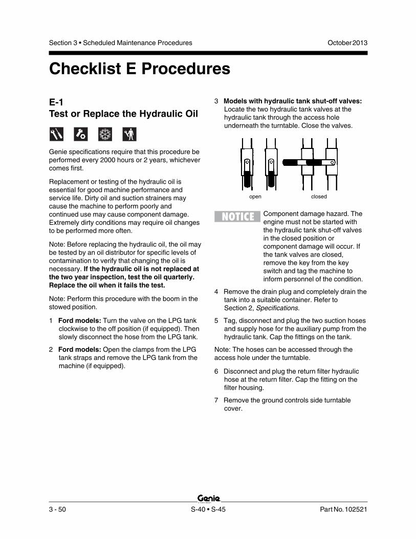
3 - 50 S-40 • S-45 Part No. 102521
October 2013Section 3 • Scheduled Maintenance Procedures
3 Models with hydraulic tank shut-off valves:Locate the two hydraulic tank valves at thehydraulic tank through the access holeunderneath the turntable. Close the valves.
Component damage hazard. Theengine must not be started withthe hydraulic tank shut-off valvesin the closed position orcomponent damage will occur. Ifthe tank valves are closed,remove the key from the keyswitch and tag the machine toinform personnel of the condition.
4 Remove the drain plug and completely drain thetank into a suitable container. Refer toSection 2, Specifications.
5 Tag, disconnect and plug the two suction hosesand supply hose for the auxiliary pump from thehydraulic tank. Cap the fittings on the tank.
Note: The hoses can be accessed through theaccess hole under the turntable.
6 Disconnect and plug the return filter hydraulichose at the return filter. Cap the fitting on thefilter housing.
7 Remove the ground controls side turntablecover.
E-1Test or Replace the Hydraulic Oil
Genie specifications require that this procedure beperformed every 2000 hours or 2 years, whichevercomes first.
Replacement or testing of the hydraulic oil isessential for good machine performance andservice life. Dirty oil and suction strainers maycause the machine to perform poorly andcontinued use may cause component damage.Extremely dirty conditions may require oil changesto be performed more often.
Note: Before replacing the hydraulic oil, the oil maybe tested by an oil distributor for specific levels ofcontamination to verify that changing the oil isnecessary. If the hydraulic oil is not replaced atthe two year inspection, test the oil quarterly.Replace the oil when it fails the test.
Note: Perform this procedure with the boom in thestowed position.
1 Ford models: Turn the valve on the LPG tankclockwise to the off position (if equipped). Thenslowly disconnect the hose from the LPG tank.
2 Ford models: Open the clamps from the LPGtank straps and remove the LPG tank from themachine (if equipped).
Checklist E Procedures
open closed

Part No. 102521 S-40 • S-45 3 - 51
October 2013 Section 3 • Scheduled Maintenance Procedures
CHECKLIST E PROCEDURES
8 Support the hydraulic tank with an appropriatelifting device.
9 Remove the hydraulic tank mounting fasteners.
10 Remove the hydraulic tank from the machine.
Crushing hazard. The hydraulictank could become unbalancedand fall if not properly supportedwhen removed from the machine.
11 Remove the hydraulic return filter housingmounting fasteners. Remove the hydraulicreturn filter housing from the hydraulic tank.
12 Remove the suction strainers from the tank andclean them using a mild solvent.
13 Rinse out the inside of the tank using a mildsolvent.
14 Install the suction strainers using a threadsealant on the threads.
15 Install the drain plug using a thread sealant onthe threads.
16 Install the hydraulic return filter housing onto thehydraulic tank.
17 Install the hydraulic tank onto the machine.
18 Install the two suction hoses to the suctionstrainers.
19 Install the supply hose for the auxiliary powerunit and the return filter hose.
20 Models with hydraulic tank shut-off valves:Open the two hydraulic tank valves at thehydraulic tank.
21 Fill the tank with hydraulic oil until the level iswithin the top 2 inches / 5 cm of the sightgauge. Do not overfill.
22 Clean up any oil that may have spilled.
23 Prime the pump. Refer to Repair Procedure6-2, How to Prime the Pump.
Note: Always use pipe thread sealant wheninstalling the suction hose fittings and the drainplug.

3 - 52 S-40 • S-45 Part No. 102521
October 2013Section 3 • Scheduled Maintenance Procedures
CHECKLIST E PROCEDURES
E-2Grease the Steer AxleWheel Bearings, 2WD Models
Genie specifications require that this procedure beperformed every 2000 hours or 2 years, whichevercomes first.
Maintaining the steer axle wheel bearings isessential for safe machine operation and servicelife. Operating the machine with loose or wornwheel bearings may cause an unsafe operatingcondition and continued use may result incomponent damage. Extremely wet or dirtyconditions or regular steam cleaning and pressurewashing of the machine may require that thisprocedure be performed more often.
1 Loosen the wheel lug nuts. Do not removethem.
2 Block the non-steering wheels. Center a liftingjack under the steer axle.
3 Raise the machine 6 inches / 15 cm Placeblocks under the drive chassis for support.
4 Remove the lug nuts. Remove the tire andwheel assembly.
5 Check for wheel bearing wear by attempting tomove the wheel hub side to side, then up anddown.
Result: There should be no side to side or upand down movement.
Skip to step 10 if there is no movement.
6 Remove the dust cap from the hub. Remove thecotter pin from the castle nut.
7 Tighten the castle nut to 158 ft-lbs / 214 Nm toseat the bearings.
Note: Rotate the hub by hand while torqueing thecastle nut to make sure the bearings seat properly.
8 Loosen the castle nut one full turn and thentorque to 35 ft-lbs / 47 Nm.
9 Check for wheel bearing wear by attempting tomove the wheel hub side to side, then up anddown.
Result: If there is no side to side or up anddown movement, continue to step 11 andgrease the wheel bearings.
Result: If there is side to side or up and downmovement, continue to step 11 and replace thewheel bearings with new ones.
Note: When replacing a wheel bearing, both theinner and outer bearings, including the pressed-inraces, must be replaced.
10 Remove the dust cap from the hub. Remove thecotter pin from the castle nut.
11 Remove the castle nut.
12 Pull the hub off of the spindle. The washer andouter bearing should fall loose from the hub.
13 Place the hub on a flat surface and gently prythe bearing seal out of the hub. Remove therear bearing.

Part No. 102521 S-40 • S-45 3 - 53
October 2013 Section 3 • Scheduled Maintenance Procedures
14 Pack both bearings with clean, fresh grease.
15 Place the large inner bearing into the rear of thehub.
16 Install a new bearing grease seal into the hubby pressing it evenly into the hub until it is flush.
Note: Always replace the bearing grease sealwhen removing the hub.
17 Slide the hub onto the yoke spindle.
Component damage hazard. Donot apply excessive force ordamage to the lip of the seal mayoccur.
18 Place the outer bearing into the hub.
19 Install the washer and castle nut.
20 Tighten the slotted nut to 158 ft-lbs / 214 Nm toseat the bearings.
21 Loosen the castle nut one full turn and thentorque to 35 ft-lbs / 47 Nm.
22 Install a new cotter pin. Bend the cotter pinto lock it in.
23 Install the dust cap, then the tire and wheelassembly. Torque the wheel lug nuts tospecification. Refer to Section 2, Specifications.
E-3Perform Engine Maintenance -Deutz and Perkins Models
Engine specifications require that this procedure beperformed every 2000 hours.
Proper engine maintenance, following the enginemanufacturer's maintenance schedule, is essentialto good engine performance and service life.Failure to perform the maintenance procedurescan lead to poor engine performance andcomponent damage.
Deutz 1011F models
Required maintenance procedures and additionalengine information is available in theDeutz 1011F Operation Manual(Deutz part number 0297 9683).
Deutz 1011F Operation ManualGenie part number 52883
Perkins models
Required maintenance procedures and additionalengine information are available in thePerkins 404-22 Operation Manual(Perkins part number TPD 1443S).
Perkins 404-22 Operation ManualGenie part number 94890
To access the engine:
Remove the engine tray retaining fastenerslocated under the engine tray. Swing the enginetray out and away from the machine and secureit from moving.
Crushing hazard. Failure to securethe engine pivot plate from movingcould result in death or seriousinjury.
CHECKLIST E PROCEDURES
3 - 54 S-40 • S-45 Part No. 102521
October 2013Section 3 • Scheduled Maintenance Procedures
CHECKLIST E PROCEDURES
E-5Perform Engine Maintenance -Deutz and Perkins Models
Engine specifications require that this procedure beperformed every 3000 hours.
Proper engine maintenance, following the enginemanufacturer's maintenance schedule, is essentialto good engine performance and service life.Failure to perform the maintenance procedurescan lead to poor engine performance andcomponent damage.
Required maintenance procedures and additionalengine information are available in theDeutz 1011F Operation Manual(Deutz part number 0297 9683) or theDeutz 2011 Operation Manual(Deutz part number 0312 3547).
Deutz 1011F Operation ManualGenie part number 52883
Deutz 2011 Operation ManualGenie part number 139320
To access the engine:
Remove the engine tray retaining fastenerslocated under the engine tray. Loosen the pivotfastener located at the platform end of theengine tray. Swing the engine tray out andaway from the machine and secure it frommoving.
Crushing hazard. Failure to securethe engine pivot plate from movingcould result in death or seriousinjury.
E-4Perform Engine Maintenance -Ford Models
Engine specifications require that this procedurebe performed every 2400 hours.
Required maintenance procedures and additionalengine information are available in theFord LRG-425 EFI Operator Handbook(Ford part number FPP 194-302) or theFord DSG-423 EFI Operator Handbook(EDI part number 1060020).
Ford LRG 425 EFI Operation ManualGenie part number 84792
Ford DSG 423 EFI Operator HandbookGenie part number 119488
To access the engine:
Remove the engine tray retaining fastenerslocated under the engine tray. Loosen the pivotfastener located at the platform end of theengine tray. Swing the engine tray out andaway from the machine and secure it frommoving.
Crushing hazard. Failure to securethe engine pivot plate from movingcould result in death or seriousinjury.

Part No. 102521 S-40 • S-45 3 - 55
October 2013 Section 3 • Scheduled Maintenance Procedures
Perkins models
Required maintenance procedures and additionalengine information are available in thePerkins 404-22 Operation Manual(Perkins part number TPD 1443S).
Perkins 404-22 Operation ManualGenie part number 94890
To access the engine:
Remove the engine tray retaining fastenerslocated under the engine tray. Loosen the pivotfastener located at the platform end of theengine tray. Swing the engine tray out andaway from the machine and secure it frommoving.
Crushing hazard. Failure to securethe engine pivot plate from movingcould result in death or seriousinjury.
E-6Perform Engine Maintenance -Deutz and Perkins Models
Engine specifications require that this procedure beperformed every 5000 hours.
Proper engine maintenance, following the enginemanufacturer's maintenance schedule, is essentialto good engine performance and service life.Failure to perform the maintenance procedurescan lead to poor engine performance andcomponent damage.
Required maintenance procedures and additionalengine information are available in theDeutz 1011F Operation Manual(Deutz part number 0297 9683) or theDeutz 2011 Operation Manual(Deutz part number 0312 3547).
Deutz 1011F Operation ManualGenie part number 52883
Deutz 2011 Operation ManualGenie part number 139320
To access the engine:
Remove the engine tray retaining fastenerslocated under the engine tray. Loosen the pivotfastener located at the platform end of theengine tray. Swing the engine tray out andaway from the machine and secure it frommoving.
Crushing hazard. Failure to securethe engine pivot plate from movingcould result in death or seriousinjury.
CHECKLIST E PROCEDURES
3 - 56 S-40 • S-45 Part No. 102521
October 2013Section 3 • Scheduled Maintenance Procedures
CHECKLIST E PROCEDURES
E-8Perform Engine Maintenance -Deutz Models
Engine specifications require that this procedure beperformed every 12,000 hours.
Proper engine maintenance, following the enginemanufacturer's maintenance schedule, is essentialto good engine performance and service life.Failure to perform the maintenance procedurescan lead to poor engine performance andcomponent damage.
Required maintenance procedures and additionalengine information are available in theDeutz 1011F Operation Manual(Deutz part number 0297 9683) or theDeutz 2011 Operation Manual(Deutz part number 0312 3547).
Deutz 1011F Operation ManualGenie part number 52883
Deutz 2011 Operation ManualGenie part number 139320
To access the engine:
Remove the engine tray retaining fastenerslocated under the engine tray. Loosen the pivotfastener located at the platform end of theengine tray. Swing the engine tray out andaway from the machine and secure it frommoving.
Crushing hazard. Failure to securethe engine pivot plate from movingcould result in death or seriousinjury.
E-7Perform Engine Maintenance -Deutz Models
Engine specifications require that this procedure beperformed every 6000 hours.
Proper engine maintenance, following the enginemanufacturer's maintenance schedule, is essentialto good engine performance and service life.Failure to perform the maintenance procedurescan lead to poor engine performance andcomponent damage.
Required maintenance procedures and additionalengine information are available in theDeutz 1011F Operation Manual(Deutz part number 0297 9683) or theDeutz 2011 Operation Manual(Deutz part number 0312 3547).
Deutz 1011F Operation ManualGenie part number 52883
Deutz 2011 Operation ManualGenie part number 139320
To access the engine:
. Remove the engine tray retaining fastenerslocated under the engine tray. Loosen the pivotfastener located at the platform end of theengine tray. Swing the engine tray out andaway from the machine and secure it frommoving.
Crushing hazard. Failure to securethe engine pivot plate from movingcould result in death or seriousinjury.

Part No. 102521 S-40 • S-45 3 - 57
October 2013 Section 3 • Scheduled Maintenance Procedures
E-9Perform Engine Maintenance -Ford Models
Engine specifications require that this procedure beperformed every 4 years.
Required maintenance procedures and additionalengine information are available in theFord LRG-425 EFI Operator Handbook(Ford part number FPP 194-302) or theFord DSG-423 EFI Operator Handbook(EDI part number 1060020) or theFord MSG-425 EFI Operator Handbook(Ford part number 1020010) .
Ford LRG 425 EFI Operation ManualGenie part number 84792
Ford DSG 423 EFI Operator HandbookGenie part number 119488
Ford MSG-425 EFI Operator HandbookGenie part number 215322
To access the engine:
Remove the engine tray retaining fastenerslocated under the engine tray. Loosen the pivotfastener located at the platform end of theengine tray. Swing the engine tray out andaway from the machine and secure it frommoving.
Crushing hazard. Failure to securethe engine pivot plate from movingcould result in death or seriousinjury.
CHECKLIST E PROCEDURES

3 - 58 S-40 • S-45 Part No. 102521
October 2013Section 3 • Scheduled Maintenance Procedures
This page intentionally left blank.
CHECKLIST E PROCEDURES

Part No. 102521 S-40 • S-45 4 - 1
October 2013 Section 4 • Repair Procedures
Repair Procedures
About This SectionMost of the procedures in this section should onlybe performed by a trained service professionalin a suitably equipped workshop. Select theappropriate repair procedure after troubleshootingthe problem.
Perform disassembly procedures to the point whererepairs can be completed. To re-assemble, performthe disassembly steps in reverse order.
Symbols Legend
Safety alert symbol—used to alertpersonnel to potential personalinjury hazards. Obey all safetymessages that follow this symbolto avoid possible injury or death.
Used to indicate the presence ofan imminently hazardous situationwhich, if not avoided, will result indeath or serious injury.
Used to indicate the presence of apotentially hazardous situationwhich, if not avoided, could resultin death or serious injury.
With safety alert symbol—used toindicate the presence of apotentially hazardous situationwhich, if not avoided, may causeminor or moderate injury.
Used to indicate the presence of apotentially hazardous situationwhich, if not avoided, may result inproperty damage.
Indicates that a specific result is expected afterperforming a series of steps.
Indicates that an incorrect result has occurredafter performing a series of steps.
Observe and Obey:Repair procedures shall be completed by aperson trained and qualified on the repair of thismachine.
Immediately tag and remove from service adamaged or malfunctioning machine.
Repair any machine damage or malfunctionbefore operating the machine.
Before Repairs Start:Read, understand and obey the safety rules andoperating instructions in the Genie S-40 andGenie S-45 Operator’s Manual on your machine.
Be sure that all necessary tools and parts areavailable and ready for use.
Use only Genie approved replacement parts.
Read each procedure completely and adhereto the instructions. Attempting shortcuts mayproduce hazardous conditions.
Unless otherwise specified, perform eachrepair procedure with the machine in thefollowing configuration:
• Machine parked on a flat, level surface
• Boom in the stowed position
• Turntable rotated with the boom betweenthe non-steering wheels
• Turntable secured with the turntablerotation lock pin
• Key switch in the off position with thekey removed
• Wheels chocked
• All external AC power supply disconnectedfrom the machine

4 - 2 S-40 • S-45 Part No. 102521
October 2013Section 4 • Repair Procedures
The platform control box contains one printedcircuit board. The ALC-500 circuit board inside theplatform control box controls all proportionalmachine functions from the platform. The joystickcontrollers at the platform controls utilize HallEffect technology and require no adjustment. Theoperating parameters of the joysticks are stored inmemory at the ECM circuit board at the platformcontrols. If a joystick error occurs or if a joystick isreplaced, it will need to be calibrated before thatparticular machine function will operate. See 1-2,How to Calibrate a Joystick.
Each joystick controller should operate smoothlyand provide proportional speed control over itsentire range of motion.
a ALC-500 circuit boardb drive/steer joystick controllerc secondary boom up/down
joystick controllerd primary boom up/down and
turntable rotate left/rightjoystick controller
1-1ALC-500 Circuit Board
Electrocution hazard. Contactwith electrically charged circuitscould result in death or seriousinjury. Remove all rings, watchesand other jewelry.
Note: When the ALC-500 circuit board is replaced,the joystick controllers will need to be calibrated.See 1-2, How to Calibrate a Joystick.
How to Remove the ALC-500Circuit Board1 Push in the red Emergency Stop button to the
off position at both the ground and platformcontrols.
2 Remove the platform control box lid retainingfasteners. Open the control box lid.
3 Locate the ALC-500 circuit board mounted tothe inside of the platform control box.
Platform Controls
bcd
a

Part No. 102521 S-40 • S-45 4 - 3
October 2013 Section 4 • Repair Procedures
1-2Joysticks
How to Calibrate a JoystickThe joysticks on this machine utilize digital HallEffect technology for proportional control. If ajoystick is disconnected or replaced, it must becalibrated before that particular machine functionwill operate.
Note: The joystick must be calibrated before thethreshold, max-out or ramping can be set.
Note: Perform this procedure with the engine off.
1 Open the platform control box.
4 Attach a grounded wrist strap to the groundscrew inside the platform control box.
Component damage hazard.Electrostatic discharge (ESD) candamage printed circuit boardcomponents. Maintain firm contactwith a metal part of the machinethat is grounded at all times whenhandling printed circuit boards ORuse a grounded wrist strap.
5 Carefully disconnect the wire connectors fromthe circuit board.
6 Remove the ALC-500 circuit board mountingfasteners.
7 Carefully remove the ALC-500 circuit boardfrom the platform control box.
PLATFORM CONTROLS
2 Pull out the red Emergency Stop button to theon position at both the ground and platformcontrols.
3 Turn the key switch to platform control. Do notstart the engine.
4 Select a joystick to calibrate.
5 Disconnect the wire harness connector from thejoystick for approximately 10 seconds or untilthe alarm sounds. Connect the wire harnessconnector to the joystick.
6 Move the joystick full stroke in either directionand hold for 5 seconds.
7 Return the joystick to the neutral position, pausefor a moment, then move the joystick full strokein the opposite direction. Hold for 5 seconds.
Result: The alarm should sound indicatingsuccessful joystick calibration.
Result: The alarm does not sound. Check theelectrical connections or replace the joystick.
8 Repeat this procedure for each joystickcontrolled machine function including the thumbrocker steer switch.
Note: No machine fuction should operate whileperforming the joystick calibration procedure.

4 - 4 S-40 • S-45 Part No. 102521
October 2013Section 4 • Repair Procedures
PLATFORM CONTROLS
How to Adjust the JoystickMax-out SettingThe max-out setting of a joystick controls themaximum speed of a joystick-controlled machinefunction. Whenever a hydraulic cylinder, drivemotor or hydraulic pump is replaced, the max-outsetting should be adjusted to maintain optimumperformance. The max-out settings on the joystickcan be changed to compensate for hydraulic pumpwear to maintain peak performance from themachine.
Note: Perform this procedure with the boom in thestowed position.
1 Pull out the red Emergency Stop button to theon position at both the ground and platformcontrols.
2 Turn the key switch to platform control. Do notstart the engine.
3 Push in the platform controls red EmergencyStop button to the off position.
4 Do not press down the foot switch.
5 Move and hold the drive enable toggle switch inthe right position and pull out the redEmergency Stop button to the on position.
6 When the alarm sounds, release the driveenable toggle switch.
7 Momentarily activate the drive enable toggleswitch in the right direction 4 times.
Result: There should be a pause and the alarmshould sound 4 times indicating that themachine is in max-out calibration mode.
Result: The alarm does not sound. Repeat steps3 through 7.
8 Start the engine from the platform controls andpress down the foot switch.
9 Start a timer and activate the machine functionthat needs to be adjusted. Record the time ittakes for that function to complete a full cycle(ie; boom up).
10 Compare the machine function time with thefunction times listed in Section 2,Specifications. Determine whether the functiontime needs to increase or decrease.
11 While the joystick is activated, adjust the max-out setting to achieve the proper function cycletime. Momentarily move the drive enable toggleswitch in the right direction to increase thefunction speed or momentarily move the driveenable toggle switch in the left direction todecrease the function speed.
Note: Each time the drive enable toggle switch ismomentarily moved, the function speed will changein 2% increments.
12 Repeat steps 9 through 11 for each joystickcontrolled machine function.

Part No. 102521 S-40 • S-45 4 - 5
October 2013 Section 4 • Repair Procedures
PLATFORM CONTROLS
13 Return the joystick to the neutral position andwait for approximately 10 seconds to allow thesettings to be saved.
Result: The alarm should sound indicating thatthe settings have been saved in memory.
Result: The alarm does not sound. Theminimum or maximum adjustment has beenobtained. No changes can be saved.
Note: Do not operate any machine function duringthe 10 second waiting time.
14 Cycle the red Emergency Stop button off, thenback on.
How to Adjust the JoystickRamp Rate SettingThe ramp rate setting of a joystick controls the timeat which it takes for the joystick to reach maximumoutput, when moved out of the neutral position. Theramp rate settings of a joystick can be changed tocompensate for hydraulic pump wear to maintainpeak performance from the machine.
Note: Perform this procedure with the boom in thestowed position.
1 Pull out the red Emergency Stop button to theon position at both the ground and platformcontrols.
2 Turn the key switch to platform control. Do notstart the engine.
3 Push in the platform controls red EmergencyStop button to the off position.
4 Do not press down the foot switch.
5 Move and hold the drive enable toggle switch inthe right position and pull out the redEmergency Stop button to the on position.
6 When the alarm sounds, release the driveenable toggle switch.
7 Momentarily activate the drive enable toggleswitch in the right direction 6 times.
Result: There should be a pause and the alarmshould sound 6 times indicating that themachine is in ramp rate calibration mode.
Result: The alarm does not sound. Repeat steps3 through 7.
8 Start the engine from the platform controls andpress down the foot switch.
9 Start a timer and simultaneously move thejoystick in either direction full stroke. Note howlong it takes the function to reach maximumspeed. This is the ramp rate.
10 Compare the function ramp rate time with thetable below and determine whether the ramprate time needs to increase or decrease.
11 Release the foot switch.

4 - 6 S-40 • S-45 Part No. 102521
October 2013Section 4 • Repair Procedures
PLATFORM CONTROLS
12 While the joystick is activated, set the ramprate. Momentarily move the drive enable toggleswitch in the right direction to increase the timeor momentarily move the drive enable toggleswitch in the left direction to decrease the time.
Note: Each time the drive enable toggle switch ismomentarily moved, the time will change in 5%increments.
13 Repeat steps 9 through 11 for each joystickcontrolled machine function.
14 Return the joystick to the neutral position andwait for approximately 10 seconds to allow thesettings to be saved.
Result: The alarm should sound indicating thatthe settings have been saved in memory.
Note: Do not operate any machine function duringthe 10 second waiting time.
15 Cycle the red Emergency Stop button off, thenback on.
Ramp rate (factory settings)
Boom up/downaccelerate 3 seconddecelerate 1 seconds
Turntable rotateaccelerate 2 secondsdecelerate 1 second
Driveaccelerate 2 secondsdecelerate to neutral 0.5 seconddecelerate, change of direction 0.5 seconddecelerate, coasting 0.75 seconddecelerate, braking 1 seconddecelerate, shift from low to high speed 1 seconddecelerate, shift from high to low speed 3 seconds

Part No. 102521 S-40 • S-45 4 - 7
October 2013 Section 4 • Repair Procedures
How to Adjust the JoystickThreshold SettingThe threshold setting of a joystick is the minimumoutput at which a function proportional valve canopen and allow the function to operate.
Note: Perform this procedure with the boom in thestowed position.
1 Pull out the red Emergency Stop button to theon position at both the ground and platformcontrols.
2 Turn the key switch to platform control. Do notstart the engine.
3 Push in the red Emergency Stop button to theoff position at the platform controls.
4 Do not press down the foot switch.
5 Move and hold the drive enable toggle switch inthe right position and pull out the redEmergency Stop button to the on position.
6 When the alarm sounds, release the driveenable toggle switch.
7 Momentarily activate the drive enable toggleswitch in the right direction 8 times.
Result: There should be a pause and the alarmshould sound 8 times indicating that themachine is in threshold calibration mode.
Result: The alarm does not sound. Repeat steps3 through 7.
8 Start the engine from the platform controls andpress down the foot switch.
9 Select a boom function joystick to set thethreshold.
10 Slowly move the joystick off center in eitherdirection just until the function begins to move.
11 Slowly move the joystick back to the neutralposition. Just before the function stops moving,move the drive enable toggle switch to eitherside to set the threshold.
Result: The alarm should sound indicating asuccessful calibration.
12 Repeat steps 9 through 11 for each boomjoystick-controlled machine function (boom up/down, boom extend/retract and turntable rotate).
13 Return the joystick to the neutral position andwait for approximately 10 seconds.
Result: The alarm should sound indicating thatthe settings have been saved in memory.
Note: Do not operate any machine function duringthe 10 second waiting time.
14 Cycle the red Emergency Stop button off, thenback on.
PLATFORM CONTROLS

4 - 8 S-40 • S-45 Part No. 102521
October 2013Section 4 • Repair Procedures
Platform Components
2-1Platform Leveling Slave Cylinder
The slave cylinder and the rotator pivot are thetwo primary supports for the platform. The slavecylinder keeps the platform level through theentire range of boom motion. It operates in aclosed-circuit hydraulic loop with the mastercylinder. The slave cylinder is equipped withcounterbalance valves to prevent movement inthe event of a hydraulic line failure.
How to Remove the PlatformLeveling Slave CylinderNote: Before cylinder removal is considered, bleedthe slave cylinder to be sure there is noair in the closed loop.
Note: When removing a hose assembly or fitting,the O-ring on the fitting and/or hose end must bereplaced and then torqued to specification duringinstallation.Refer to Section 2, Hydraulic Hose and FittingTorque Specifications.
1 Extend the primary boom until the slave cylinderbarrel-end pivot pin is accessible.
2 Raise the primary boom slightly and placeblocks under the platform for support.
3 Lower the primary boom until the platform isresting on the blocks just enough to support theplatform.
Note: Do not rest the entire weight of the boom onthe blocks.
4 Protect the slave cylinder rod from damage.
S-40 Models:
5 Tag, disconnect and plug the hydraulic hosesfrom the slave cylinder at the union locatednear the platform rotate counterbalance valvemanifold and connect them together using aconnector. Cap the fittings on the cylinder.
Bodily injury hazard. Sprayinghydraulic oil can penetrate andburn skin. Loosen hydraulicconnections very slowly to allowthe oil pressure to dissipategradually. Do not allow oil tosquirt or spray.
S-45 Models:
6 Tag, disconnect and plug the slave cylinderhoses at the union.
7 Pull the slave cylinder hoses through theplatform rotator.
8 Remove the pin retaining fastener fromthe slave cylinder rod-end pivot pin. Do notremove the pin.
9 Remove the external retaining fastener from thebarrel-end pivot pin.
10 Use a soft metal drift to drive the rod-end pivotpin out.
11 Use a soft metal drift and drive the barrel-endpin out.
12 Carefully pull the cylinder out of the boom.
Component damage hazard. Hosescan be damaged if they are kinkedor pinched.
How to Bleed the Slave CylinderNote: Do not start the engine. Use auxiliary powerfor this procedure.
1 Raise the primary boom to a horizontal position.
2 Move the platform level toggle switch up anddown through two platform leveling cycles toremove any air that might be in the system.

Part No. 102521 S-40 • S-45 4 - 9
October 2013 Section 4 • Repair Procedures
PLATFORM COMPONENTS
2-2Platform Rotator
The platform rotator is a hydraulically activatedhelical gear assembly used to rotate the platform160 degrees.
How to Remove thePlatform Rotator
Component damage hazard. Markthe platform mounting weldmentand the rotator flange beforeremoving the platform mountingweldment. The platform mountingweldment must be replaced in theexact same position on the rotatorflange as it was before removal. Ifa new rotator is installed or therotator is disassembled, properalignment can be achieved byrotating the rotator all the way tothe left and then installing theplatform mounting weldment allthe way in the left position.
Note: When removing a hose assembly or fitting,the O-ring on the fitting and/or hose end must bereplaced and then torqued to specification duringinstallation. Refer to Section Two, Hydraulic Hoseand Fitting Torque Specifications.
1 Remove the platform and platform support.
S-40 Models:
2 Tag, disconnect and plug the hydraulic hosesfrom the platform rotator. Cap the fittings on therotator.
Bodily injury hazard. Sprayinghydraulic oil can penetrate andburn skin. Loosen hydraulicconnections very slowly to allowthe oil pressure to dissipategradually. Do not allow oil to squirtor spray.
S-45 Models:
3 Tag and disconnect the hydraulic hoses fromthe "V1" and "V2" ports on the counterbalancevalve manifold located on the platform rotatorand connect them together using a connector.Cap the fittings on the manifold.
4 Support the platform leveling arms and platformmounting weldment with an appropriate liftingdevice, but do not apply any lifting pressure.
All Models:
5 Remove the six mounting bolts from theplatform mounting weldment. Remove thecenter bolt and slide the platform mountingweldment off of the platform rotator.
Crushing hazard. The platformmounting weldment could becomeunbalanced and fall if it is notproperly supported.
6 Support the platform rotator with an appropriatelifting device. Do not apply any lifting pressure.

4 - 10 S-40 • S-45 Part No. 102521
October 2013Section 4 • Repair Procedures
7 Support the platform leveling slave cylinder.Protect the cylinder rod from damage.
8 Remove the pin retaining fasteners from boththe slave cylinder rod-end pivot pin, and therotator pivot pin.
9 Use a soft metal drift to drive both pins out, thenremove the platform rotator from the machine.
Crushing hazard. The platformrotator could become unbalancedand fall if it is not properlysupported.
How to Bleed the PlatformRotatorNote: This procedure will require two people. Do notstart the engine. Use auxiliary power for thisprocedure.
1 Move the function enable toggle switch to eitherside and activate the platform rotate toggleswitch to the right then the left through twoplatform rotation cycles, then hold the switch tothe right position until the platform is fullyrotated to the right.
2 Connect a clear hose to the top bleed valve.Place the other end of the hose in a containerto collect any drainage. Secure the container tothe boom.
3 Open the top bleed valve on the rotator, but donot remove it.
a top bleed valveb bottom bleed valvec containerd clear hose
4 Move the function enable toggle switch to eitherside and hold the platform rotate toggle switchto the left position until the platform is fullyrotated to the left. Continue holding the toggleswitch until air stops coming out of the bleedvalve. Close the bleed valve.
Crushing hazard. Keep clear ofthe platform during rotation.
5 Connect the clear hose to the bottom bleedvalve and open the valve. Do not remove thebleed valve.
6 Move the function enable toggle switch to eitherside and hold the platform rotate toggle switchto the right position until the platform is fullyrotated to the right. Continue holding the toggleswitch until air stops coming out of the bleedvalve. Close the bleed valve.
Crushing hazard. Keep clear ofthe platform during rotation.
7 Remove the hose from the bleed valve andclean up any hydraulic oil that may have spilled.
8 Rotate the platform fully in both directions andinspect the bleed valves for leaks.
PLATFORM COMPONENTS
a
d c b

Part No. 102521 S-40 • S-45 4 - 11
October 2013 Section 4 • Repair Procedures
2-3Platform Overload System
The platform overload system is designed toprevent the machine from continuing to operatewhen the load in the platform exceeds maximumrated capacity. Refer to the machine serial label formaximum capacity information.
If maximum platform capacity is exceeded, thealarm will sound at the platform controls and theplatform overload indicator lights will flash at boththe ground and platform controls. The ground andplatform controls will become disabled and theengine will stop. Before normal machine operationcan continue, the excess load will need to beremoved from the platform.
If the excess load cannot be removed or if theoperator at the platform controls is unable to correctthe overloaded condition, another person at theground controls can operate the machine usingauxiliary power. There will be limited control ofboom functions from the ground controls whenusing auxiliary power. Auxiliary power can be usedto correct the overloaded platform condition in orderto resume normal, safe operation of the machine.
Note: When the engine is shut off in an overloadedcondition, it will not be possible to re-start theengine until the overloaded condition is corrected.
How to Calibrate the PlatformOverload System (if equipped)
Calibration of the platform overload system isessential to safe machine operation. Continued useof an improperly calibrated platform overloadsystem could result in the system failing to sensean overloaded platform. The stability of themachine is compromised and it could tip over.
Note: Perform this procedure with the machine on afirm, level surface.
1 Turn the key switch to platform control. Start theengine and level the platform.
2 Determine the maximum platform capacity.Refer to the machine serial plate.
3 Remove all weight, tools and accessories fromthe platform.
Note: Failure to remove all weight, tools andaccessories from the platform will result in anincorrect calibration.
4 Using a suitable lifting device, place a testweight equal to the maximum platform capacityat the center of the platform floor.
PLATFORM COMPONENTS

4 - 12 S-40 • S-45 Part No. 102521
October 2013Section 4 • Repair Procedures
7 Move the platform up and down by hand, so itbounces approximately 2.5 to 5 cm / 1 to 2inches. Allow the platform to settle.
Result: The overload indicator lights are off andthe alarm does not sound. Proceed to step 8.
Result: The overload indicator lights are flashingat the platform and ground controls, the alarm issounding, and the engine stops. Repeat thisprocedure beginning with step 5.
Note: There may be a 2 second delay before theplatform overload indicator light and alarmresponds.
8 Add an additional 10 lb / 4.5 kg test weight tothe platform.
Result: The overload indicator light is flashing atboth the ground and platform controls, the alarmis sounding, and the engine stops. Proceed tostep 9.
Result: The overload indicator light is off at boththe ground and platform controls, and the alarmdoes not sound. Remove the additional 10 lb /4.5 kg test weight. Repeat this procedurebeginning with step 6.
Note: There may be a 2 second delay before theoverload indicator lights and alarm turn off.
9 Test all machine functions from the platformcontrols.
Result: All platform control functions should notoperate.
10 Turn the key switch to ground control.
5 Move the platform up and down by hand, so itbounces approximately 2.5 to 5 cm / 1 to 2inches. Allow the platform to settle.
Result: The overload indicator lights are off andthe alarm does not sound. Proceed to step 6.
Result: The overload indicator lights are flashingat the platform and ground controls, the alarm issounding, and the engine stops. Slowly tightenthe load spring adjustment nut in a clockwisedirection in 10° increments until the overloadindicator light turns off, and the alarm does notsound. Proceed to step 8.
Note: The platform will need to be moved up anddown and allowed to settle between eachadjustment.
Note: There may be a 2 second delay before theplatform overload indicator light and alarmresponds.
6 Move the platform up and down by hand, so itbounces approximately 2.5 to 5 cm / 1 to 2inches. Allow the platform to settle.
Result: The overload indicator lights are off atthe platform and ground controls, and the alarmdoes not sound. Slowly loosen the load springadjustment nut in a counterclockwise directionin 10° increments until the overload indicatorlight flashes at both the platform and groundcontrols, the alarm sounds, and the enginestops. Proceed to step 7.
Result: The overload indicator lights are flashingat the platform and ground controls, the alarm issounding, and the engine stops. Repeat thisprocedure beginning with step 5.
Note: The platform will need to be moved up anddown and allowed to settle between eachadjustment.
Note: There may be a 2 second delay before theplatform overload indicator light and alarmresponds.
PLATFORM COMPONENTS

Part No. 102521 S-40 • S-45 4 - 13
October 2013 Section 4 • Repair Procedures
11 Test all machine functions from the groundcontrols.
Result: All ground control functions utilizingengine power should not operate. (Only limitedground control functions utilizing APU powershould function).
12 Using a suitable lifting device, lift the test weightoff the platform floor.
Result: The platform overload indicator lightshould be off at both the ground and platformcontrols and the alarm should not sound.
Note: There may be a 2 second delay before theoverload indicator lights and alarm turn off.
13 Start the engine from the ground controls.
14 Test all machine functions from the groundcontrols.
Result: All ground control functions shouldoperate normally.
15 Turn the key switch to platform control.
16 Test all machine functions from the platformcontrols.
Result: All platform control functions shouldoperate normally.
PLATFORM COMPONENTS

4 - 14 S-40 • S-45 Part No. 102521
October 2013Section 4 • Repair Procedures
3-1Jib Boom
How to Remove the Jib BoomNote: Perform this procedure with the boom in thestowed position.
Note: When removing a hose assembly or fitting,the O-ring on the fitting and/or hose end must bereplaced and then torqued to specification duringinstallation.Refer to Section 2, Hydraulic Hose and FittingTorque Specifications.
1 Remove the platform.
2 Remove the platform mounting weldment,and the platform rotator. See 2-2, How toRemove the Platform Rotator.
3 From the ground controls, raise the jib boom toa horizontal position.
4 Support the jib boom with a strap from anoverhead crane.
5 Tag, disconnect and plug the hydraulic hosesfrom the jib boom lift cylinder. Cap the fittingson the cylinder.
Bodily injury hazard. Sprayinghydraulic oil can penetrate andburn skin. Loosen hydraulicconnections very slowly to allowthe oil pressure to dissipategradually. Do not allow oil tosquirt or spray.
6 Remove the hose cover, hoses and cables fromthe side of the jib boom and set them aside.
Component damage hazard. Hosesand cables can be damaged if theyare kinked or pinched.
7 Place blocks under the platform leveling cylinderfor support. Protect the cylinder rod fromdamage.
8 Remove the pin retaining fasteners from the jibboom lift cylinder barrel-end pivot pin. Do notremove the pin.
9 Attach a lifting strap from an overhead crane tothe lug on the rod end of the jib boom liftcylinder.
10 Use a soft metal drift to remove the jib boom liftcylinder rod-end pivot pin.
11 Use a soft metal drift to remove the jib boom liftcylinder barrel-end pivot pin, then remove thejib boom cylinder.
Crushing hazard. The jib boomlift cylinder could becomeunbalanced and fall when it isremoved from the machine if it isnot properly attached to theoverhead crane.
12 Remove the pin retaining fasteners from the jibboom pivot pin. Use a soft metal drift to removethe pin, then remove the jib boom from thebellcrank.
Crushing hazard. The jib boomcould become unbalanced and fallwhen it is removed from themachine if it is not properlyattached to the overhead crane.
Jib Boom Components, S-45

Part No. 102521 S-40 • S-45 4 - 15
October 2013 Section 4 • Repair Procedures
3-2Jib Boom Lift Cylinder
How to Remove the Jib BoomLift CylinderNote: Perform this procedure with the boom in thestowed position.
Note: When removing a hose assembly or fitting,the O-ring on the fitting and/or hose end must bereplaced and then torqued to specification duringinstallation. Refer to Section 2, Hydraulic Hose andFitting Torque Specifications.
1 Raise the jib boom slightly and place blocksunder the platform mounting weldment. Thenlower the jib boom until the platform is restingon the blocks just enough to support theplatform.
Note: Do not rest the entire weight of the boom onthe blocks.
2 Tag, disconnect and plug the jib boom liftcylinder hydraulic hoses. Cap the fittings on thecylinder.
Bodily injury hazard. Sprayinghydraulic oil can penetrate andburn skin. Loosen hydraulicconnections very slowly to allowthe oil pressure to dissipategradually. Do not allow oil tosquirt or spray.
3 Remove the pin retaining fasteners from the jibboom lift cylinder rod-end pivot pin. Do notremove the pin.
4 Use a soft metal drift to tap the jib boom liftcylinder rod-end pivot pin half way out. Thenlower one of the leveling arms to the ground.Tap the pin the other direction and lower theopposite leveling arm. Do not remove the pin.
5 Support the jib boom lift cylinder with a liftingdevice.
6 Remove the pin retaining fastener from the jibboom lift cylinder barrel-end pivot pin. Use asoft metal drift to remove the barrel-end pin andlet the cylinder hang down.
Crushing hazard. The platformand jib boom could becomeunbalanced and fall when the jibboom barrel-end pivot pin isremoved if not properly supported.
7 Attach a lifting strap from an overhead crane tothe lug on the rod end of the jib boom liftcylinder.
8 Use a soft metal drift to remove the jib boom liftcylinder rod-end pin. Remove the cylinder fromthe machine.
Crushing hazard. The jib boom liftcylinder could become unbalancedand fall when removed from themachine if not properly attached tothe overhead crane.
JIB BOOM COMPONENTS, S-45

4 - 16 S-40 • S-45 Part No. 102521
October 2013Section 4 • Repair Procedures
4-1Cable Track
The primary boom cable track guides the cablesand hoses running up the boom. It can be repairedlink by link without removing the cables and hosesthat run through it. Removing the entire primaryboom cable track is only necessary whenperforming major repairs that involve removing theprimary boom.
How to Remove the Cable TrackNote: When removing a hose assembly or fitting,the O-ring on the fitting and/or hose end must bereplaced and then torqued to specification duringinstallation. Refer to Section 2, Hydraulic Hose andFitting Torque Specifications.
1 Raise the primary boom to a horizontal position.
2 Locate the cables from the cable track to theplatform control box. Number each cable andits entry location at the platform control box.
3 Disconnect the cables from the platform controlbox.
4 Remove the electrical outlet box bracketmounting fasteners. Remove the outlet box andlay it to the side.
5 Remove the hose and cable clamp from theplatform support.
Boom Components
6 Tag, disconnect and plug the hydraulic hosesfrom the counterbalance valve manifold locatedon the platform rotator. Cap the fittings on themanifold.
Bodily injury hazard. Sprayinghydraulic oil can penetrate andburn skin. Loosen hydraulicconnections very slowly to allowthe oil pressure to dissipategradually. Do not allow oil tosquirt or spray.
7 Tag, disconnect and plug the hydraulic hosesfrom the platform leveling cylinder at the unionand connect the hoses from the cylindertogether using a connector.
Bodily injury hazard. Sprayinghydraulic oil can penetrate andburn skin. Loosen hydraulicconnections very slowly to allowthe oil pressure to dissipategradually. Do not allow oil tosquirt or spray.
8 Locate all electrical cables that enter the cabletrack.
9 Tag and disconnect the electrical connectors forall cables that enter the cable track.
10 Remove the retaining fasteners from theelectrical connector receptacles for the cablesthat enter the cable track.
11 Remove the fasteners from the drive speed limitswitch mounted on the side of the cable track atthe pivot end of the boom. Do not disconnectthe wiring.

Part No. 102521 S-40 • S-45 4 - 17
October 2013 Section 4 • Repair Procedures
12 Remove the fasteners from the side panel onthe lower cable track, then remove the panel.Pull all of the cables out of the channel.
13 Remove the cable cover on the side of theboom.
14 Place blocks in between the upper and lowercable tracks and secure the upper and lowertracks together.
Crushing hazard. If the upper andlower cable tracks are not properlysecured together, the cable trackcould become unbalanced and fallwhen it is removed from themachine.
15 Attach a lifting strap from an overhead crane tothe cable track.
16 Remove the mounting fasteners from the uppercable track at the platform end of the extensionboom.
17 Remove the cable track mounting fasteners thatattach the lower cable track to the boom.
18 Remove the cable track from the machine andplace it on a structure capable of supporting it.
Crushing hazard. The cable trackcould become unbalanced and fallif it is not properly attached to theoverhead crane.
Component damage hazard.Hoses and cables can bedamaged if they are kinked orpinched.
How to Repair the Cable TrackComponent damage hazard.The boom cable track can bedamaged if it is twisted.
Note: A cable track repair kit is available throughthe Genie Industries Service Parts Department,part no. 81007. The kit includes a 4 link section ofcable track.
1 Visually inspect the cable track and determinewhich 4 link section needs to be replaced.
2 Remove the snap-on cable track spacers.
3 Carefully remove the external snap rings fromthe pivot pins at each end of the 4-link sectionto be removed.
4 Lift up the hoses and cables and carefullyremove the damaged 4 link section of cabletrack.
Component damage hazard. Hosesand cables can be damaged if theyare kinked or pinched.
5 Remove the snap-on spacers from thereplacement section of the cable track.
6 Lift up the hoses and cables and carefully insertthe new 4 link section of cable track.
Component damage hazard.Hoses and cables can bedamaged if they are kinked orpinched.
7 Connect the ends of the replacement cabletrack section to the existing cable track usingthe pivot pins and external snap rings.
Note: Be sure the pivot pins are installed from theinside out so the external snap rings are on theoutside of the cable track.
8 Operate the boom extend/retract functionthrough a full cycle to ensure smooth operationof the new section of cable track.
BOOM COMPONENTS

4 - 18 S-40 • S-45 Part No. 102521
October 2013Section 4 • Repair Procedures
BOOM COMPONENTS
1 Remove the platform. See 2-1, How to Removethe Platform.
2 Remove the platform rotator and leveling slavecylinder. See 2-3, How to Remove the PlatformRotator.
3 S-45 Models: Remove the jib boom. See 3-1,How to Remove the Jib Boom.
4 Remove the mounting fasteners from the jibboom/platform rotate valve manifold on the endof the boom. Remove the manifold and set itaside.
5 Remove the fasteners from the limit switchmounted on the side of the cable track. Do notdisconnect the wiring.
6 Support the cable track with an overhead crane.
7 Remove the hose/cable clamp from the pivotend of the boom.
8 Remove the hose/cable clamp at the platformend of the cable track.
9 Remove the fasteners from the large cable trackguide at the platform end of the cable track.Remove the guide.
10 Remove the cotter pin from the clevis pin at theplatform end of the cable track. Remove theclevis pin.
Note: Always replace the cotter pin with a new onewhen removing a clevis pin.
11 Remove the fasteners from the side panel onthe cable track to access the cable trackmounting fasteners.
4-2Boom
How to Remove the BoomConsult the Genie Industries Service Departmentfor instructions on how to safely remove the boomassembly from the machine. Failure to read andfollow the warnings listed below could result indeath or serious injury.
Bodily injury hazard. Thisprocedure requires specific repairskills, lifting equipment and asuitable workshop. Attempting thisprocedure without these skills andtools could result in death orserious injury and significantcomponent damage. Dealerservice is strongly recommended.
Note: Perform this procedure with the boom in thestowed position.
Note: When removing a hose assembly or fitting,the O-ring on the fitting and/or hose end must bereplaced and then torqued to specification duringinstallation.Refer to Section 2, Hydraulic Hose and FittingTorque Specifications.

Part No. 102521 S-40 • S-45 4 - 19
October 2013 Section 4 • Repair Procedures
12 Remove the cable track mounting fasteners,then remove the cable track from the boom andlay it off to the side.
Component damage hazard.The boom cable track can bedamaged if it is twisted.
Component damage hazard.Hoses can be damaged if they arekinked or pinched.
13 Remove the turntable end cover.
14 Remove the retaining fastener from the mastercylinder rod-end pivot pin. Use a soft metal driftto remove the pin. Pull the cylinder back andsecure it from moving.
Component damage hazard.When pulling the master cylinderback, be sure not to damage themaster cylinder hoses or fittings.
15 Remove the fasteners from the limit switchmounted to the turntable riser at the pivot end ofthe boom. Do not disconnect the wiring.
16 Tag, disconnect and plug the extension cylinderhydraulic hoses. Cap the fittings on the cylinder.
Bodily injury hazard. Sprayinghydraulic oil can penetrate andburn skin. Loosen hydraulicconnections very slowly to allowthe oil pressure to dissipategradually. Do not allow oil tosquirt or spray.
17 Attach an overhead 5 ton / 4500 kg crane to thecenter point of the boom.
18 Attach a similar lifting device to the boom liftcylinder.
19 Use the overhead crane to lift the boom to ahorizontal position.
20 Place support blocks under the boom liftcylinder, across the turntable.
21 Remove the pin retaining fastener from theboom lift cylinder rod-end pin. Use a soft metaldrift to remove the pin.
Crushing hazard. The boom liftcylinder will fall if not properlysupported.
22 Lower the rod end of the lift cylinder ontosupport blocks. Protect the cylinder rod fromdamage.
23 Remove the pin retaining fastener from theboom pivot pin.
24 Use a soft metal drift to remove the boom pivotpin, then carefully remove the boom from themachine.
Crushing hazard. The primaryboom could become unbalancedand fall when removed from themachine if not properly attached tothe overhead crane.

4 - 20 S-40 • S-45 Part No. 102521
October 2013Section 4 • Repair Procedures
How to Disassemble the BoomNote: Complete disassembly of the boom is onlynecessary if the secondary boom tube must bereplaced. The extension cylinder can be removedwithout completely disassembling the boom. See 4-4, How to Remove the Extension Cylinder.
1 Remove the boom. See 4-2, How to Remove theBoom.
2 Place blocks under the extension cylinder forsupport.
3 Remove the external snap rings from theextension cylinder barrel-end pivot pin at thepivot end of the primary boom tube. Use a softmetal drift to remove the pin.
4 Remove and label the wear pads from the topside of the primary boom tube at the platformend of the boom.
Note: Pay careful attention to the location andamount of shims used with each wear pad.
5 Attach a lifting strap from an overhead crane tothe secondary boom tube at the platform end ofthe boom for support.
6 Support and slide the secondary boom tube outof the primary boom tube. Place the secondaryboom tube on blocks for support.
Crushing hazard. The secondaryboom tube could becomeunbalanced and fall when removedfrom the primary boom tube if notproperly supported.
Note: During removal, the overhead crane strap willneed to be carefully adjusted for proper balancing.
7 Remove and label the wear pads from the topside of the secondary boom tube at the platformend of the boom.
8 Remove the trunnion pin retaining fasteners atthe base end of the secondary boom tube. Usea slide hammer to remove the trunnion pins.
9 Carefully rotate the base end of the extensioncylinder until the pin mounting bore is in avertical position.
10 Remove the external snap rings from theextension cylinder rod-end pivot pin at theplatform end of the secondary boom tube. Use asoft metal drift to remove the pin.
11 Support and slide the extension cylinder out ofthe base end of the secondary boom tube.Place the extension cylinder on blocks forsuppport.
Crushing hazard. The extensioncylinder may become unbalancedand fall when removed from thesecondary boom tube if notproperly supported.
Note: During removal, the overhead crane strap willneed to be carefully adjusted for proper balancing.
12 Remove the label the wear pads from theextension cylinder.
Note: Pay careful attention to the location of eachwear pad.

Part No. 102521 S-40 • S-45 4 - 21
October 2013 Section 4 • Repair Procedures
4-3Boom Lift Cylinder
The boom lift cylinder raises and lowers the boom.The boom lift cylinder is equipped withcounterbalance valves to prevent movement in theevent of a hydraulic line failure.
How to Remove the BoomLift Cylinder
Bodily injury hazard. Thisprocedure requires specific repairskills, lifting equipment and asuitable workshop. Attempting thisprocedure without these skills andtools could result in death orserious injury and significantcomponent damage. Dealerservice is strongly recommended.
Note: When removing a hose assembly or fitting,the O-ring on the fitting and/or hose end must bereplaced and then torqued to specification duringinstallation. Refer to Section 2, Hydraulic Hose andFitting Torque Specifications.
1 Raise the boom to a horizontal position.
2 Place support blocks across the turntable underthe boom lift cylinder.
3 Attach a 5 ton / 5000 kg overhead crane to theboom at the platform end for support. Do not liftthe boom.
4 Support and secure both ends of the boom liftcylinder to a second overhead crane or similarlifting device.
5 Tag, disconnect and plug the boom lift cylinderhydraulic hoses. Cap the fittings on the cylinder.
Bodily injury hazard. Sprayinghydraulic oil can penetrate andburn skin. Loosen hydraulicconnections very slowly to allowthe oil pressure to dissipategradually. Do not allow oil tosquirt or spray.
6 Remove the pin retaining fastener from theboom lift cylinder rod-end pivot pin. Use a softmetal drift to remove the pin. Lower the liftcylinder onto the blocks. Protect the cylinderrod from damage.
Crushing hazard. The lift cylindercould become unbalanced and fallif it is not properly supported.
7 Remove the four mounting fasteners from thelift cylinder barrel-end pivot pin mounting plate.
8 With the lift cylinder being supported by theoverhead crane, pull the cylinder toward theplatform to remove it from the machine.
Crushing hazard. The lift cylindercould become unbalanced and fallif it is not properly supported.
Component damage hazard. Thecables and hydraulic hoses can bedamaged if the lift cylinder ispulled across them.
9 Using auxiliary power, activate the boom downfunction so the cylinder will retract. Retract thecylinder just enough until the rod end of thecylinder will clear the mounting bracket on theboom. Turn the machine off.
BOOM COMPONENTS

4 - 22 S-40 • S-45 Part No. 102521
October 2013Section 4 • Repair Procedures
BOOM COMPONENTS
4-4Extension Cylinder
The extension cylinder extends and retracts theboom extension tube. The extension cylinder isequipped with counterbalance valves to preventmovement in the event of a hydraulic line failure.
How to Remove theExtension Cylinder
This procedure requires specificrepair skills, lifting equipment anda suitable workshop. Attemptingthis procedure without these skillsand tools could cause death orserious injury and significantcomponent damage. Dealerservice is strongly recommended.
Note: When removing a hose assembly or fitting,the O-ring on the fitting and/or hose end must bereplaced and then torqued to specification duringinstallation. Refer to Section Two, Hydraulic Hoseand Fitting Torque Specifications.
1 Extend the boom until the extension cylinderrod-end pivot pins are accessible in theextension tube.
2 Remove the master cylinder. See 4-5, How toRemove the Master Cylinder.
3 Raise the boom to a horizontal position.
4 Remove the external snap rings from theextension cylinder rod-end pins (at the platformend). Use a soft metal drift to remove the pins.
5 Remove the turntable end cover.
6 Tag, disconnect and plug the extension cylinderhydraulic hoses. Cap the fittings on thecylinder.
Bodily injury hazard. Sprayinghydraulic oil can penetrate andburn skin. Loosen hydraulicconnections very slowly to allowthe oil pressure to dissipategradually. Do not allow oil tosquirt or spray.
7 Remove the barrel-end pivot pin retainingfasteners.
8 Place a rod through the barrel-end pivot pin andtwist to remove the pin.
9 Support and slide the extension cylinder out ofthe pivot end of the boom.
Crushing hazard. The extensioncylinder will fall when it is removedfrom the extension boom if it is notproperly supported.
Note: Note the length of the cylinder after removal.The cylinder must be at the same length forinstallation.

Part No. 102521 S-40 • S-45 4 - 23
October 2013 Section 4 • Repair Procedures
BOOM COMPONENTS
4-5Platform LevelingMaster Cylinder
The master cylinder acts as a pump for the slavecylinder. It is part of the closed circuit hydraulicloop that keeps the platform level through theentire range of boom motion. The master cylinderis located at the base of the boom.
How to Remove the PlatformLeveling Master CylinderNote: When removing a hose assembly or fitting,the O-ring on the fitting and/or hose end must bereplaced and then torqued to specification duringinstallation. Refer to Section Two, Hydraulic Hoseand Fitting Torque Specifications.
1 Remove the turntable end cover to access themaster cylinder.
2 Raise the boom until the master cylinderrod-end pivot pin is accessible.
3 Tag, disconnect and plug the master cylinderhydraulic hoses. Cap the fittings on thecylinder.
Bodily injury hazard. Sprayinghydraulic oil can penetrate andburn skin. Loosen hydraulicconnections very slowly to allowthe oil pressure to dissipategradually. Do not allow oil tosquirt or spray.
4 Attach a lifting strap from an overhead crane tothe lug on the rod end of the master cylinder.
5 Remove the pin retaining fasteners from themaster cylinder barrel-end pivot pin.
6 Place a rod through the barrel-end pivot pin andtwist to remove the pin.
7 Remove the pin retaining fastener from the rod-end pivot pin.
8 Use a soft metal drift to remove the pin.
9 Remove the master cylinder from the machine.
Crushing hazard. The mastercylinder could become unbalancedand fall if it is not properly attachedto the overhead crane.

4 - 24 S-40 • S-45 Part No. 102521
October 2013Section 4 • Repair Procedures
5-1RPM Adjustment - Deutz Models
Refer to Maintenance Procedure B-11, Check andAdjust the Engine RPM.
5-2RPM Adjustment - PerkinsModels
Refer to Maintenance Procedure B-11, Check andAdjust the Engine RPM.
Engines
5-3Flex Plate
The flex plate acts as a coupler between the engineand the pump. It is bolted to the engine flywheeland has a splined center to drive the pump.
a pumpb pump shaftc pump couplerd flex plate with raised splinee engine flywheelf 0.18 inch / 4.6 mm gap - Deutz Models
0.070 inch / 1.8 mm gap - Perkins Models0.0625 inch / 1.6 mm gap - Ford LRG-4250.080 inch / 2 mm gap - Ford DSG-423
How to Remove the Flex PlateDeutz models:
1 Remove the tailpipe bracket mounting fastenersfrom the engine bell housing.
2 Support the drive pump assembly with anappropriate lifting device.
3 Remove all of the engine bell housing fasteners.
4 Carefully pull the pump and bell housingassembly away from the engine and secure itfrom moving.
Component damage hazard. Hosescan be damaged if they are kinkedor pinched.
5 Remove the flex plate mounting fasteners.Remove the flex plate from the flywheel.
a b c d e
f

Part No. 102521 S-40 • S-45 4 - 25
October 2013 Section 4 • Repair Procedures
ENGINES
Ford LRG-425 EFI models:
1 Disconnect the electrical connector for theoxygen sensor at the tailpipe. Do not removethe oxygen sensor.
2 Remove the engine oil dipstick fasteners fromthe muffler bracket. Remove the dipstick fromthe engine.
3 Remove the muffler retaining fasteners from theexhaust pipe.
4 Support the muffler and bracket assembly withan overhead crane or other suitable liftingdevice.
5 Remove the muffler bracket mounting fasteners.Carefully remove the muffler and bracketassembly from the engine.
6 Support the engine with a suitable lifting device.Do not lift it.
7 Remove the engine plate to vibration isolatorfasteners.
8 Remove the engine mounting plate to bellhousing fasteners.
9 Raise the engine slightly to take the weight offof the engine mounting plate.
10 Slide the engine mounting plate towards thepump as far as it will go.
11 Support the drive pump assembly with anappropriate lifting device.
12 Remove all of the engine bell housing fasteners.
13 Carefully pull the pump and bell housingassembly away from the engine and secure itfrom moving.
Component damage hazard. Hosescan be damaged if they are kinkedor pinched.
14 Remove the flex plate mounting fasteners.Remove the flex plate from the flywheel.
Ford DSG-423 EFI models:
1 Disconnect the electrical connectors from bothoxygen sensors at the tailpipe and exhaustmanifold. Do not remove the oxygen sensors.
2 Remove the exhaust pipe fasteners at themuffler.
3 Support the muffler and bracket assembly with asuitable lifting device.
4 Remove the muffler bracket mounting fastenersfrom the bell housing. Carefully remove themuffler and bracket assembly from the engine.
5 Support the engine with an overhead crane orother suitable lifting device. Do not lift it.
6 Remove the engine mounting plate to bellhousing fasteners.
7 Raise the engine slightly using the overheadcrane and place a block of wood under the oilpan for support.
8 Support the drive pump assembly with anoverhead crane or other suitable lifting device.Do not apply any lifting pressure.

4 - 26 S-40 • S-45 Part No. 102521
October 2013Section 4 • Repair Procedures
After serial number 13739: Torque the flexplate mounting bolts in sequence to20 ft-lbs / 27 Nm.
Deutz models:Torque the flex plate mounting bolts insequence to28 ft-lbs / 38 Nm.
Perkins models:Before serial number 7472: Torque the flexplate mounting bolts in sequence to28 ft-lbs / 38 Nm.From serial number 7472 to 13773: Torque theflex plate mounting bolts in sequence to49 ft-lbs / 66 Nm.After serial number 13773: Torque the flexplate mounting bolts in sequence to14 ft-lbs / 19.1 Nm.
3 Install the pump coupler onto the pump shaftwith the set screw toward the pump. Leave theappropriate gap between coupler and pump endplate for your engine.
a pumpb pump shaftc pump couplerd flex plate with raised splinee engine flywheelf 0.18 inch / 4.6 mm gap - Deutz Models
0.070 inch / 1.8 mm gap - Perkins Models0.0625 inch / 1.6 mm gap - Ford LRG-4250.080 inch / 2 mm gap - Ford DSG-423
4 Apply Loctite® removable thread sealant to thepump coupler set screw. Torque the set screwto 61 ft-lbs / 83 Nm.
5 Install the pump and bell housing assembly.
9 Remove all of the engine bell housing retainingfasteners.
10 Carefully pull the pump and bell housingassembly away from the engine and secure itfrom moving.
Component damage hazard. Hosescan be damaged if they are kinkedor pinched.
11 Remove the flex plate mounting fasteners.Remove the flex plate from the flywheel.
Perkins models:
1 Remove the fuel filter/water separator mountingfasteners.
2 Remove the fuel filter/water separator and lay itto the side. Do not disconnect the hoses.
3 Support the drive pump assembly with anappropriate lifting device.
4 Remove all of the engine bell housing fasteners.
5 Carefully pull the pump and bell housingassembly away from the engine and secure itfrom moving.
Component damage hazard. Hosescan be damaged if they are kinkedor pinched.
6 Remove the flex plate mounting fasteners.Remove the flex plate from the flywheel.
How to Install the Flex Plate1 Install the flex plate onto the engine flywheel
with the raised spline towards the pump.
2 Apply Loctite® removable thread sealant to thescrews. Torque the flex plate in a star patternusing the following values.
Ford models:Before serial number 13740: Torque the flexplate mounting bolts in sequence to24 ft-lbs / 32 Nm.
ENGINES
a b c d e
f

Part No. 102521 S-40 • S-45 4 - 27
October 2013 Section 4 • Repair Procedures
1 6
5 2
34
C C
CC
CC
CC
7 8
9
C
6 1
9
5
7
32
8
4
A A
B
B
B
B
B
B
B
CC
BB
A
A
B
1
2
3
4
5
6
7
Ford LRG 425 models(after serial number 7596)
Ford DSG 423 models
Perkins models(after serial number 7471)
ENGINES
Ford LRG-425 models:Before serial number 7597: Torque the bellhousing mounting bolts in sequence to23 ft-lbs / 31 Nm.After serial number 7596: Torque the bellhousing mounting bolts labeled "C" in sequenceto 47 ft-lbs / 63 Nm. Torque the bell housingmounting bolts labeled "B" in sequence to61 ft-lbs / 83 Nm.
Ford DSG-423 models:Torque the bell housing mounting bolts labeled"A" and "B" in sequence to 28 ft-lbs / 38 Nmand the mounting bolts labeled "C" to 49 ft-lbs /66 Nm. Then torque the bell housing mountingbolts labeled "A" and "B" in sequence to 40 ft-lbs / 54 Nm and the mounting bolts labeled "C"to 70 ft-lbs / 95 Nm.
Deutz models:Before serial number 7544: Torque the bellhousing mounting bolts in sequence to28 ft-lbs / 38 Nm.After serial number 7543: Torque the bellhousing mounting bolts in sequence to47 ft-lbs / 63 Nm.
Perkins models:Before serial number 7472: Torque the bellhousing mounting bolts in sequence to28 ft-lbs / 38 Nm.After serial number 7471: Torque the bellhousing mounting bolts labeled "B" in sequenceto 28 ft-lbs / 38 Nm and the mounting boltslabeled "A" to 49 ft-lbs / 66 Nm. Then torque thebell housing mounting bolts labeled "B" insequence to 40 ft-lbs / 54 Nm and the mountingbolts labeled "A" to 70 ft-lbs / 95 Nm.
Component damage hazard. Wheninstalling the pump, do not forcethe pump coupler into the flexplateor damage to the pump shaft sealmay occur.
Component damage hazard. Donot force the drive pump duringinstallation or the flex plate teethmay become damaged.
10
6 1
8
4
11
7 5
92
12
3
C
C C
C
C
C
C
CC
C
C
C
Deutz 2011 models(after serial number 7543)
Deutz 1011 models(before serial number 7544)
Ford LRG 425 models(before serial number 7597)
Perkins models(before serial number 7472)
1
2
3
4
5
67
8
1
2
34
5
6
7
8
9
10
11 12
1
2
34
5
6
7
8
9
10
11 12

4 - 28 S-40 • S-45 Part No. 102521
October 2013Section 4 • Repair Procedures
5-4Engine Fault Codes -Ford Models
How to Retrieve Engine FaultCodesWhen an engine malfunction is detected by theElectronic Control Module (ECM), a fault code isrecorded and the check engine light will turn on atthe ground controls. Special equipment is requiredto retrieve fault codes stored within the ECM.Contact Genie Industries Service Department forassistance in retrieving fault codes.
Note: Perform this procedure with the key switch inthe off position.
1 Open the ground controls side cover and locatethe run/test toggle switch on the side of theground control box.
2 Pull out the red Emergency Stop button to theon position at both the ground and platformcontrols.
3 Quickly activate and release the start toggleswitch/button. Do not start the engine.(before serial no. 7597)
4 Move and hold the run/test toggle switch to thetest position.
Result: The check engine light should turn on.The check engine light should begin to blink.
5 Continue to hold the run/test toggle switch in thetest position and count the blinks.
Note: If any fault codes are present, the ECM willuse the check engine light to blink a three digitcode.It will blink the first digit of a three digit code,pause, blink the second digit, pause, and then blinkthe third digit. For example: the check engine lightblinks 5 consecutive times, blinks 3 times and then1 time. That would indicate code 531. There will bea longer pause between codes.
6 Refer to Section 5, Fault Codes, for definition ofengine fault codes.
Note: Once a fault code has been retrieved and therepair has been completed, the ECM memory mustbe reset to clear the fault code from the ECM. SeeHow to Clear Engine Fault Codes from the ECM.
How to Clear Engine FaultCodes from the ECMNote: Perform this procedure with the engine offand the key switch in the off position.
1 Open the engine side turntable cover and locatethe battery.
2 Disconnect the negative battery cable from thebattery for a minimum of 5 minutes.
Electrocution/burn hazard. Contactwith electrically charged circuitscould result in death or seriousinjury. Remove all rings, watchesand other jewelry.
3 Connect the negative battery cable to thebattery.
ENGINES

Part No. 102521 S-40 • S-45 4 - 29
October 2013 Section 4 • Repair Procedures
Hydraulic Pumps
6-1Function Pump
How to Remove theFunction PumpNote: When removing a hose assembly or fitting,the O-ring on the fitting and/or hose end must bereplaced and then torqued to specification duringinstallation.Refer to Section 2, Hydraulic Hose and FittingTorque Specifications.
1 Models with hydraulic tank shut-off valves:Locate the two hydraulic tank valves at thehydraulic tank through the access holeunderneath the turntable. Close the valves.
Component damage hazard. Theengine must not be started with thehydraulic tank shut-off valves inthe closed position or componentdamage will occur. If the tankvalves are closed, remove the keyfrom the key switch and tag themachine to inform personnel of thecondition.
Models without hydraulic tank shut-offvalves: Remove the drain plug from thehydraulic tank and completely drain the tankinto a suitable container. See capacityspecifications.
2 Tag, disconnect and plug the function pumphydraulic hoses. Cap the fittings on the pump.
Bodily injury hazard. Sprayinghydraulic oil can penetrate andburn skin. Loosen hydraulicconnections very slowly to allowthe oil pressure to dissipategradually. Do not allow oil tosquirt or spray.
3 Remove the pump mounting bolts. Carefullyremove the pump.
Models with hydraulic tank shut-off valves:
Component damage hazard. Besure to open the two hydraulic tankvalves and prime the pump afterinstalling the pump.
Models without hydraulic tank shut-off valves:
Component damage hazard. Besure to fill the hydraulic tank tospecification and prime the pumpafter installing the pump.
open closed

4 - 30 S-40 • S-45 Part No. 102521
October 2013Section 4 • Repair Procedures
HYDRAULIC PUMPS
6-2Drive Pump
The drive pump is a bi-directional variabledisplacement piston pump. The pump output iscontrolled by the electro-proportional controller,located on the pump. The only adjustment that canbe made to the pump is the neutral or nulladjustment. Any internal service to the pumpshould only be performed at an authorized EatonHydraulics center. Call Genie Industries ServiceDepartment to locate your local authorized servicecenter.
How to Remove the Drive PumpComponent damage hazard. Thework area and surfaces where thisprocedure will be performed mustbe clean and free of debris thatcould get into the hydraulic systemand cause severe componentdamage. Dealer service isrecommended.
Note: When removing a hose assembly or fitting,the O-ring on the fitting and/or hose end must bereplaced and then torqued to specification duringinstallation.Refer to Section 2, Hydraulic Hose and FittingTorque Specifications.
1 Disconnect the electrical connection at theelectro-proportional controller located on thedrive pump.
2 Models with hydraulic tank shut-off valves:Locate the two hydraulic tank valves at thehydraulic tank through the access holeunderneath the turntable. Close the valves.
Component damage hazard. Theengine must not be started with thehydraulic tank shut-off valves inthe closed position or componentdamage will occur. If the tankvalves are closed, remove the keyfrom the key switch and tag themachine to inform personnel of thecondition.
Models without hydraulic tank shut-offvalves: Remove the drain plug from thehydraulic tank and completely drain the tankinto a suitable container. See capacityspecifications.
3 Tag and disconnect and plug the hydraulichoses from the drive and function pumps.Cap the fittings on the pumps.
Bodily injury hazard. Sprayinghydraulic oil can penetrate andburn skin. Loosen hydraulicconnections very slowly to allowthe oil pressure to dissipategradually. Do not allow oil tosquirt or spray.
open closed

Part No. 102521 S-40 • S-45 4 - 31
October 2013 Section 4 • Repair Procedures
a
4 Support the pump with a lifting device andremove the two drive pump mounting fasteners.
5 Carefully pull the drive pump out until the pumpcoupler separates from the flex plate.
6 Remove the drive pump from the machine.
Component damage hazard. Thehydraulic pump may becomeunbalanced and fall if not properlysupported.
Models with hydraulic tank shut-off valves:
Component damage hazard. Besure to open the two hydraulic tankvalves and prime the pump afterinstalling the pump.
Models without hydraulic tank shut-off valves:
Component damage hazard. Besure to fill the hydraulic tank tospecification and prime the pumpafter installing the pump.
How to Prime the Pump1 Connect a 0 to 600 psi / 0 to 50 bar pressure
gauge to the test port on the drive pump.
2 Remove the safety pin (if equipped) from theengine pivot plate latch.
Note: The engine pivot plate latch is located underthe engine turntable pivot plate at the counterweightend of the machine.
3 Open the engine pivot plate latch and swing theengine pivot plate out and away from themachine.
4 Ford models: Close the valve on the LPG tankthen disconnect the hose from the tank. Movethe fuel select switch to the LPG position.
Perkins models: Disconnect the engine wiringharness from the fuel solenoid at the injectorpump.
Deutz models: Hold the manual fuel shutoffvalve clockwise to the closed position.
a manual fuel shutoff valve
5 Have another person crank the engine with thestarter motor for 15 seconds, wait 15 seconds,then crank the engine an additional 15 secondsor until the pressure reaches 320 psi / 22 bar.
6 Ford models: Connect the LPG hose to theLPG tank and open the valve on the tank. Movethe fuel select switch to the gasoline position.
Perkins models: Connect the engine wiringharness to the fuel solenoid.
Deutz models: Release the manual fuel shutoffvalve.
7 Start the engine from the ground controls andcheck for hydraulic leaks.
HYDRAULIC PUMPS

4 - 32 S-40 • S-45 Part No. 102521
October 2013Section 4 • Repair Procedures
Manifolds
7-1Function Manifold Components
The function manifold is located underneath the ground controls side turntable cover.
Index SchematicNo. Description Item Function Torque
1 Flow regulator valve,0.8 gpm / 3.03 L/min .......................... AA ......... platform rotate and
jib boom (S-45) ................................. 20-25 ft-lbs / 27-34 Nm
1 Flow regulator valve,0.6 gpm / 2.27 L/min .......................... AA ......... platform rotate (S-40) ........................ 20-25 ft-lbs / 27-34 Nm
2 Check valve ....................................... AB ......... Differential sensing circuit,platform rotate right andjib boom down (S-45) ........................ 10-12 ft-lbs / 14-16 Nm
3 Solenoid valve, 2 position 3 way ....... AC ........ Platform level up/down ..................... 20-25 ft-lbs / 27-34 Nm
4 Check valve ....................................... AD ........ Differential sensing circuit,platform level up ............................... 10-12 ft-lbs / 14-16 Nm
5 Solenoid valve, 2 position 3 way ....... AE ......... Platform level up/down ..................... 20-25 ft-lbs / 27-34 Nm
6 Check valve ....................................... AF ......... Differential sensing circuit,boom up/down .................................. 10-12 ft-lbs / 14-16 Nm
7 Differential sensing valve,150 psi / 10.3 bar ............................... AG ........ Turntable rotate circuit ...................... 30-35 ft-lbs / 41-47 Nm
8 Differential sensing valve,150 psi / 10.3 bar ............................... AH ........ Boom up/down circuit ....................... 30-35 ft-lbs / 41-47 Nm
9 Relief valve, 2200 psi / 152 bar ........ AI .......... Boom down relief .............................. 20-25 ft-lbs / 27-34 Nm
10 Flow regulator valve,0.1 gpm / 0.38 L/min .......................... AJ ......... Bleeds off differential sensing
valves to tank .................................... 20-25 ft-lbs / 27-34 Nm
11 Check valve ....................................... AK ......... Differential sensing circuit,boom up/down .................................. 10-12 ft-lbs / 14-16 Nm
12 Relief valve, 1950 psi / 134 bar ........ AL ......... Extend cylinder relief ........................ 20-25 ft-lbs / 27-34 Nm
13 Check valve ....................................... AM ........ Differential sensing circuit,boom extend/retract .......................... 10-12 ft-lbs / 14-16 Nm
14 Flow regulator valve,2.0 gpm / 7.6 L/min ............................ AN ........ Steer left/right circuit ......................... 30-35 ft-lbs / 41-47 Nm
15 Check valve ....................................... AO ........ Platform level up .......................................... 14 ft-lbs / 19 Nm
16 Diagnostic nipple ............................... AP ......... Testing
This list continues. Please turn the page

Part No. 102521 S-40 • S-45 4 - 33
October 2013 Section 4 • Repair Procedures
AA AB AC AD AE AF AG AH AI AJ AK AL AM AN
AO
AP
AQ
AR
AS
AT
AU
AV
AW
AX
AY
AZ
BABBBCBDBEBFBGBHBI
35 34 33 32 31 30 29 28
15
27
18
17
19
21
20
16
22
23
24
25
26
1 2 3 4 5 6 7 8 9 10 11 12 13 14
36
MANIFOLDS
4 - 34 S-40 • S-45 Part No. 102521
October 2013Section 4 • Repair Procedures
Function Manifold Components, continued
Index SchematicNo. Description Item Function Torque
18 Relief valve,2900 psi / 200 bar ............................. AQ ........ System relief (S-45) .......................... 30-35 ft-lbs / 41-47 Nm
18 Relief valve,2600 psi / 179 bar ............................. AQ ........ System relief (S-40) .......................... 30-35 ft-lbs / 41-47 Nm
19 Flow regulator valve,4.5 gpm / 17.03 L/min ........................ AR ........ Boom extend/retract circuit ............... 30-35 ft-lbs / 41-47 Nm
20 Check valve ....................................... AS ......... Blocks flow from auxiliary pumpto function pump ............................... 30-35 ft-lbs / 41-47 Nm
21 Solenoid valve, 3 position 4 way ...... AT ......... Steer left/right .................................... 30-35 ft-lbs / 41-47 Nm
22 Solenoid valve, 2 position 3 way ...... AU ........ Boom extend .................................... 30-35 ft-lbs / 41-47 Nm
23 Solenoid valve, 2 position 3 way ...... AV ......... Boom retract ..................................... 30-35 ft-lbs / 41-47 Nm
24 Proportional solenoid valve .............. AW ........ Boom up/down circuit ....................... 20-25 ft-lbs / 27-34 Nm
25 Solenoid valve, 2 position 3 way ...... AX ......... Boom up ........................................... 30-35 ft-lbs / 41-47 Nm
26 Solenoid valve, 2 position 3 way ...... AY ......... Boom down ....................................... 30-35 ft-lbs / 41-47 Nm
27 Solenoid valve, 3 position 4 way ...... AZ ......... Turntable rotate ................................ 20-25 ft-lbs / 27-34 Nm
28 Check valve ....................................... BA ......... Platform level down .......................... 10-12 ft-lbs / 14-16 Nm
29 Proportional solenoid valve .............. BB ......... Turntable rotate left/right .................. 20-25 ft-lbs / 27-34 Nm
30 Counterbalance valve ....................... BC ........ Platform level up ............................... 30-35 ft-lbs / 41-47 Nm
31 Needle Valve .................................... BD ........ Platform level circuit ......................... 20-25 ft-lbs / 27-34 Nm
32 Counterbalance valve ....................... BE ......... Platform level down .......................... 30-35 ft-lbs / 41-47 Nm
33 Solenoid valve, 3 position 4 way ...... BF ......... Platform rotate and jib boomup/down (S-45) ................................. 20-25 ft-lbs / 27-34 Nm
34 Differential sensing valve,150 psi / 10.3 bar ............................... BG ........ Differential sensing circuit,
meters flow to functions .................... 30-35 ft-lbs / 41-47 Nm
35 Check valve ....................................... BH ........ Differential sensing circuit,platform rotate left andjib boom up (S-45) ............................ 10-12 ft-lbs / 14-16 Nm
36 Diagnostic nipple .............................. BI .......... Testing
MANIFOLDS

Part No. 102521 S-40 • S-45 4 - 35
October 2013 Section 4 • Repair Procedures
MANIFOLDS
AA AB AC AD AE AF AG AH AI AJ AK AL AM AN
AO
AP
AQ
AR
AS
AT
AU
AV
AW
AX
AY
AZ
BABBBCBDBEBFBGBHBI
35 34 33 32 31 30 29 28
15
27
18
17
19
21
20
16
22
23
24
25
26
1 2 3 4 5 6 7 8 9 10 11 12 13 14
36

4 - 36 S-40 • S-45 Part No. 102521
October 2013Section 4 • Repair Procedures
MANIFOLDS
7-2Valve Adjustments -Function Manifold
How to Adjust the SystemRelief ValveNote: Perform this procedure with the boom in thestowed position.
1 Connect a 0 to 5000 psi / 0 to 350 bar pressuregauge to the PTEST port on the functionmanifold.
2 Start the engine from the ground controls.
3 Hold the function enable/rpm select toggleswitch to the high idle position. Activate andhold the boom retract toggle switch with theboom fully retracted.
4 Observe the pressure reading on the pressuregauge. Refer to Section 2, Specifications.
5 Turn the engine off. Use a wrench to hold therelief valve and remove the cap (item AQ).
6 Adjust the internal hex socket. Turn it clockwiseto increase the pressure or counterclockwise todecrease the pressure. Install the relief valvecap.
Tip-over hazard. Do not adjustthe relief valve higher thanspecified.
7 Repeat steps 2 through 5 and recheck reliefvalve pressure.
8 Remove the pressure gauge.

Part No. 102521 S-40 • S-45 4 - 37
October 2013 Section 4 • Repair Procedures
MANIFOLDS
7-3Jib Select, Platform Rotate and Generator Manifold Components
Index SchematicNo. Description Item Function Torque
1 Counterbalance valve ........................ CA ........ Platform rotate right .......................... 30-35 ft-lbs / 41-47 Nm
2 Counterbalance valve ........................ CB ........ Platform rotate left ............................. 30-35 ft-lbs / 41-47 Nm
3 Relief valve ........................................ CD ........ Generator overload relief .................. 30-35 ft-lbs / 41-47 Nm
4 Solenoid valve ................................... CE ........ Controls generator on / off ................ 50-55 ft-lbs / 68-75 Nm
5 Solenoid valve, 2 position 3 way ....... CC ........ Platform rotate/jib boom select ......... 18-20 ft-lbs / 25-27 Nm
CA
CB
CC
CD
CE
1
2
3
4
5
Jib Select Manifold
Generator Manifold
Platform Rotate Manifold

4 - 38 S-40 • S-45 Part No. 102521
October 2013Section 4 • Repair Procedures
MANIFOLDS
7-4Brake Manifold Components (before serial number 7569)
Index SchematicNo. Description Item Function Torque
1 Solenoid valve, 2 position 3 way ... DA ........... Brake release ................................... 20-25 ft-lbs / 27-34 Nm
2 Orifice, 0.025 inch / 0.635 mm ....... DB ........... Turntable rotation brake release
DA
DB
1
2

Part No. 102521 S-40 • S-45 4 - 39
October 2013 Section 4 • Repair Procedures
MANIFOLDS
7-5Brake/Two-Speed Manifold Components (after serial number 7568)
Index SchematicNo. Description Item Function Torque
1 Orifice, 0.025 inch / 0.63 mm ......... EA ........... Turntable rotation brake release
2 Solenoid valve, 2 position 3 way ... EB ........... Brake release ................................... 20-25 ft-lbs / 27-34 Nm
3 Solenoid valve, 2 position 3 way ... EC ........... Two-speed motor shift ..................... 20-25 ft-lbs / 27-34 Nm
4 Check valve .................................... ED ........... Brake release circuit ......................... 20-25 ft-lbs / 27-34 Nm
EA EB EC
ED
1 32
4

4 - 40 S-40 • S-45 Part No. 102521
October 2013Section 4 • Repair Procedures
7-6Oscillate Directional Valve Components
The oscillate directional valve is mounted inside the drive chassis at the non-steer end.
IndexNo. Description Function Torque
1 Cap ................................................................... Breather ............................................ 20-25 ft-lbs / 27-33 Nm
2 Spool valve ....................................................... Directional control
2 Relief valve ....................................................... Pressure adjustment
1
2
MANIFOLDS
3

Part No. 102521 S-40 • S-45 4 - 41
October 2013 Section 4 • Repair Procedures
MANIFOLDS
How to Set Up the OscillateDirectional ValveNote: Adjustment of the oscillate directional valvelinkage is only necessary when the linkage or valvehas been replaced.
1 Lower the boom to the stowed position.
2 Use a "bubble type" level to be sure the floor iscompletely level.
Tip-over hazard. Failure toperform this procedure on a levelfloor could compromise thestability of the machine resulting inthe machine tipping over.
3 Check the tire pressure in all four tires and addair if needed to meet specification.
Note: The tires on some machines are foam-filledand do not need air added to them.
4 Remove the drive chassis cover and the non-steer axle covers.
5 Place a "bubble type" level across the drivechassis non-steer end. Check to be sure thedrive chassis is completely level.
6 To level the drive chassis, start the engine andloosen the lock nuts on both sides of theurethane cushions.
7 Push up or pull down on the threaded rod untilthe machine is completely level.
8 Verify that the ground and drive chassis arecompletely level.
9 Tighten the nuts on both sides of the urethanecushions until they are snug. Tighten thelocknuts.
10 Verify that the ground and drive chassis arecompletely level.
11 Measure the distance between the drivechassis and the non-steer axle on both sides(from the inside of the drive chassis).
Note: If the distance is not equal and theadjustment to the linkage was completed with theground and drive chassis level, repeat steps 6through 11 OR consult Genie Industries ServiceDepartment.
4 - 42 S-40 • S-45 Part No. 102521
October 2013Section 4 • Repair Procedures
7-7Valve Adjustments - OscillateRelief Valve
How to Adjust the Oscillate ReliefValve Pressure1 Remove the drive chassis cover from the non-
steer end of the machine.
2 Connect a 0 to 2000 psi / 0 to 150 bar pressuregauge to the diagnostic nipple located near theoscillate directional valve.
3 Disconnect the directional valve linkage, byremoving the heim joint and retaining fastenerfrom the axle.
4 Start the engine from the platform controls.
5 With the engine running, manually activate thevalve and observe the pressure reading on thepressure gauge.
Oscillate relief valve specification
Pressure 950 psi65.5 bar
6 Turn the engine off.
7 Locate the relief valve on the directional valveand remove the cap.
8 Adjust the internal screw. Turn it clockwise toincrease the pressure or counterclockwise todecrease the pressure. Install the valve cap.
Tip-over hazard. Do not adjust therelief valve higher than specified.
9 Repeat steps 4 through 7 and manually activatethe valve to confirm the valve pressure.
10 Turn the engine off, remove the pressure gaugeand assemble the directional valve linkage.
11 Install the cover on the non-steer end of thedrive chassis.
MANIFOLDS

Part No. 102521 S-40 • S-45 4 - 43
October 2013 Section 4 • Repair Procedures
MANIFOLDS
7-8Traction Manifold Components, 2WD (before serial number 7569)
The traction manifold is mounted inside the drive chassis at the non-steer end.
Index SchematicNo. Description Item Function Torque
1 Relief valve, 210 psi / 14.5 bar ......... FA ......... Charge pressure circuit .................... 30-35 ft-lbs / 41-47 Nm
2 Flow divider/combiner valve ............. FB ......... Controls flow to drive motorsin forward and reverse ................ 90-100 ft-lbs / 122-136 Nm
3 Orifice, 0.070 inch / 1.78 mm ............ FC ......... Equalizes flow across flowdivider/combiner valve (item FB)
4 Shuttle valve, 3 position 3 way .......... FD ......... Charge pressure, hot oil shuttle ........ 50-55 ft-lbs / 68-75 Nm
5 Diagnostic nipple ............................... FE ......... Testing
2WD
FA FB
FC
FD
FE5
4
1 2
3

4 - 44 S-40 • S-45 Part No. 102521
October 2013Section 4 • Repair Procedures
MANIFOLDS
7-9Traction Manifold Components, 2WD (after serial number 7568)
The traction manifold is mounted inside the drive chassis at the non-steer end.
Index SchematicNo. Description Item Function Torque
1 Relief valve, 280 psi / 19.3 bar ......... GA ........ Charge pressure circuit .................... 30-35 ft-lbs / 41-47 Nm
2 Flow divider/combiner valve ............. GB ........ Controls flow to drive motorsin forward and reverse ................ 90-100 ft-lbs / 122-136 Nm
3 Check valve ....................................... GC ........ Drive circuit ....................................... 30-35 ft-lbs / 41-47 Nm
4 Check valve ....................................... GD ........ Drive circuit ....................................... 30-35 ft-lbs / 41-47 Nm
5 Flow divider/combiner valve .............. GE ........ Controls flow to drive motorsin forward and reverse ...................... 50-55 ft-lbs / 68-75 Nm
6 Orifice, 0.070 inch / 1.78 mm ............ GF ........ Equalizes flow across flowdivider/combiner valve (item GB)
GA
GB
GC
GD
GE
GF6
2
5
3
4
1

Part No. 102521 S-40 • S-45 4 - 45
October 2013 Section 4 • Repair Procedures
MANIFOLDS
7-10Valve Adjustments, 2WDDrive Manifold
How to Adjust the Hot Oil ShuttleRelief ValveNote: The pressure differential between the chargepump relief valve (located in the drive pump) andthe hot oil shuttle relief valve (located in the drivemanifold) is necessary to return hot oil from theclosed loop drive circuit to the hydraulic tank forcooling. This pressure differential must bemaintained at 40 psi / 14.5 bar.
Note: The following procedure will require twopeople.
1 Open the engine side turntable cover andconnect a 0 to 600 psi / 0 to 41 bar pressuregauge to the diagnostic nipple on the drivepump.
2 Start the engine from the platform controls andallow the engine to run at high idle. Note thepressure reading on the pressure gauge.
3 Turn the engine off and connect a0 to 600 psi / 0 to 41 bar pressure gauge to thediagnostic nipple located on the drive manifold.
4 Start the engine from the platform controls anddrive the machine slowly in the forwarddirection. Note the pressure reading on thepressure gauge.
5 Turn the engine off, and remove the hot oilshuttle relief valve cap (item FA). Adjust theinternal hex socket clockwise to increase thepressure or counterclockwise to decrease thepressure. Install the valve cap.(before serial no. 7569)
5 Turn the engine off, and remove the hot oilshuttle relief valve cap (item GA). Adjust theinternal hex socket clockwise to increase thepressure or counterclockwise to decrease thepressure. Install the valve cap.(after serial no. 7568)
6 Repeat steps 4 and 5 until the pressure readingon the guage is 40 psi / 2.8 bar less than thepressure reading at the pump.

4 - 46 S-40 • S-45 Part No. 102521
October 2013Section 4 • Repair Procedures
7-11Traction Manifold Components, 4WD (before serial number 7569)
The traction manifold is mounted inside the drive chassis at the non-steer end.
Index SchematicNo. Description Item Function Torque
1 Flow divider/combiner valve ............. HA ........ Controls flow to steerend drive motors inforward/reverse ........................... 90-100 ft-lbs / 122-136 Nm
2 Flow divider/combiner valve .............. HB ........ Controls flow to non-steerend drive motors inforward/reverse ........................... 90-100 ft-lbs / 122-136 Nm
3 Orifice, 0.070 inch / 1.778 mm .......... HC ........ Rear drive motor circuit
4 Orifice, 0.070 inch / 1.778 mm .......... HD ........ Equalizes pressure on both sidesof flow divider/combiner valve 7
5 Shuttle valve, 3 position 3 way .......... HE ........ Charge pressure, hot oil shuttle ........ 50-55 ft-lbs / 68-75 Nm
6 Diagnostic nipple ............................... HF ......... Testing
7 Flow divider/combiner valve .............. HG ........ Controls flow to flowdivider/combiner valves1 and 2 ........................................ 90-100 ft-lbs / 122-136 Nm
8 Relief valve, 210 psi / 14.5 bar .......... HH ........ Charge pressure circuit ..................... 30-35 ft-lbs / 41-47 Nm
9 Orifice, 0.052 inch / 1.32 mm ............ HI .......... Front drive motor circuit
MANIFOLDS

Part No. 102521 S-40 • S-45 4 - 47
October 2013 Section 4 • Repair Procedures
MANIFOLDS
HA
HB
HC
HD
HE
HF
HG
HH
HI
1
7
2
3
4
5
6
9
8

4 - 48 S-40 • S-45 Part No. 102521
October 2013Section 4 • Repair Procedures
7-12Traction Manifold Components, 4WD (from serial number 7568 to 15822)
The traction manifold is mounted inside the drive chassis at the non-steer end.
Index SchematicNo. Description Item Function Torque
1 Relief valve, 280 psi / 19.3 bar ......... JA ......... Charge pressure circuit .................... 35-40 ft-lbs / 48-54 Nm
2 Flow divider/combiner valve .............. JB ......... Controls flow to non-steer enddrive motors in forwardand reverse ................................... 80-90 ft-lbs / 108-122 Nm
3 Check valve ....................................... JC ......... Steer end drive motor circuit ............. 35-40 ft-lbs / 48-54 Nm
4 Check valve ....................................... JD ......... Non-steer end drive motor circuit ...... 35-40 ft-lbs / 48-54 Nm
5 Flow divider/combiner valve .............. JE ......... Controls flow to flowdivider/combiner valves2 and 13 ........................................ 80-90 ft-lbs / 108-122 Nm
6 Check valve ....................................... JF ......... Non-steer end drive motor circuit ...... 60-70 ft-lbs / 81-95 Nm
7 Orifice, 0.040 inch / 1 mm ................. JG ......... Equalizes pressure on both sidesof flow divider/combiner valve 5
8 Orifice, 0.040 inch / 1 mm ................. JH ......... Equalizes pressure on both sidesof flow divider/combiner valve 2
9 Orifice, 0.040 inch / 1 mm ................. JI ........... Equalizes pressure on both sidesof flow divider/combiner valve 13
10 Check valve ....................................... JJ .......... Steer end drive motor circuit ............. 60-70 ft-lbs / 81-95 Nm
11 Check valve ....................................... JK ......... Steer end drive motor circuit ............. 35-40 ft-lbs / 48-54 Nm
12 Shuttle valve, 3 position 3 way .......... JL .......... Charge pressure circuit thatdirects hot oil out of low pressureside of drive pump ........................ 80-90 ft-lbs / 108-122 Nm
13 Flow divider/combiner valve .............. JM ......... Controls flow to steer enddrive motors in forwardand reverse ................................... 80-90 ft-lbs / 108-122 Nm
14 Check valve ....................................... JN ......... Non-steer end drive motor circuit ...... 35-40 ft-lbs / 48-54 Nm
MANIFOLDS

Part No. 102521 S-40 • S-45 4 - 49
October 2013 Section 4 • Repair Procedures
MANIFOLDS
JA
JB
JC
JD
JE
JF
JN
JM
JI
JL
JK
JJ
JH JG
10
11
13
4
5
3
2
1
14
12
6
789

4 - 50 S-40 • S-45 Part No. 102521
October 2013Section 4 • Repair Procedures
7-13Traction Manifold Components, 4WD (from serial number 15823)
The traction manifold is mounted inside the drive chassis at the non-steer end.
Index SchematicNo. Description Item Function Torque
1 Relief valve, 280 psi / 19.3 bar ......... KA ......... Charge pressure circuit .................... 55-60 ft-lbs / 74-81 Nm
2 Flow divider/combiner valve ............. KB ......... Controls flow to non-steer enddrive motors in forwardand reverse ................................... 80-90 ft-lbs / 108-122 Nm
3 Check valve ....................................... KC ........ Steer end drive motor circuit ............ 55-60 ft-lbs / 74-81 Nm
4 Check valve ....................................... KD ........ Non-steer end drive motor circuit ..... 55-60 ft-lbs / 74-81 Nm
5 Check valve ....................................... KE ......... Non-steer end drive motor circuit ... 70-75 ft-lbs / 95-100 Nm
6 Flow divider/combiner valve ............. KF ......... Controls flow to flowdivider/combiner valves2 and 13 ........................................ 80-90 ft-lbs / 108-122 Nm
7 Orifice, 0.040 inch / 1 mm .................. KG ........ Equalizes pressure on both sidesof flow divider/combiner valve 5
8 Orifice, 0.040 inch / 1 mm .................. KH ........ Equalizes pressure on both sidesof flow divider/combiner valve 2
9 Orifice, 0.040 inch / 1 mm .................. KI .......... Equalizes pressure on both sidesof flow divider/combiner valve 13
11 Shuttle valve, 3 position 3 way ......... KJ ......... Charge pressure circuit thatdirects hot oil out of low pressureside of drive pump ............................ 35-40 ft-lbs / 48-54 Nm
10 Check valve ....................................... KK ......... Steer end drive motor circuit .......... 55-60 ft-lbs / 95-100 Nm
12 Check valve ....................................... KL ......... Steer end drive motor circuit .......... 70-75 ft-lbs / 95-100 Nm
13 Flow divider/combiner valve ............. KM ........ Controls flow to steer enddrive motors in forwardand reverse ................................... 80-90 ft-lbs / 108-122 Nm
14 Check valve ....................................... KN ........ Non-steer end drive motor circuit ..... 55-60 ft-lbs / 74-81 Nm
MANIFOLDS

Part No. 102521 S-40 • S-45 4 - 51
October 2013 Section 4 • Repair Procedures
KA
KB
KC
KD
KE
KF
KGKHKI
KJ
KK
KL
KM
KN
4WD
9 8 7
10
11
13
6
5
3
2
4
1
14
12
MANIFOLDS

4 - 52 S-40 • S-45 Part No. 102521
October 2013Section 4 • Repair Procedures
MANIFOLDS
7-14Valve Adjustments, 4WDDrive Manifold
How to Adjust the Hot Oil ShuttleRelief ValveNote: The pressure differential between the chargepump relief valve (located in the drive pump) andthe hot oil shuttle relief valve (located in the drivemanifold) is necessary to return hot oil from theclosed loop drive circuit to the hydraulic tank forcooling. This pressure differential must bemaintained at 40 psi / 14.5 bar.
Note: The following procedure will require twopeople.
1 Open the engine side turntable cover andconnect a 0 to 600 psi / 0 to 41 bar pressuregauge to the diagnostic nipple on the drivepump.
2 Start the engine from the platform controls andallow the engine to run at high idle. Note thepressure reading on the pressure gauge.
3 Turn the engine off and connect a0 to 600 psi / 0 to 41 bar pressure gauge to thediagnostic nipple located on the drive manifold.
4 Start the engine from the platform controls anddrive the machine slowly in the forwarddirection. Note the pressure reading on thepressure gauge.
5 Turn the engine off, and remove the hot oilshuttle relief valve cap (item HH). Adjust theinternal hex socket clockwise to increase thepressure or counterclockwise to decrease thepressure. Install the valve cap.(before serial no. 7569)
5 Turn the engine off, and remove the hot oilshuttle relief valve cap (item JA). Adjust theinternal hex socket clockwise to increase thepressure or counterclockwise to decrease thepressure. Install the valve cap.(from serial no. 7569 to 15822)
5 Turn the engine off, and remove the hot oilshuttle relief valve cap (item KA). Adjust theinternal hex socket clockwise to increase thepressure or counterclockwise to decrease thepressure. Install the valve cap.(from serial no. 15823)
6 Repeat steps 4 and 5 until the pressure readingon the guage is 40 psi / 2.8 bar less than thepressure reading at the pump.

Part No. 102521 S-40 • S-45 4 - 53
October 2013 Section 4 • Repair Procedures
MANIFOLDS
7-15Valve Coils
How to Test a CoilA properly functioning coil provides anelectromagnetic force which operates the solenoidvalve. Critical to normal operation is continuitywithin the coil. Zero resistance or infiniteresistance indicates the coil has failed.
Since coil resistance is sensitive to temperature,resistance values outside specification can produceerratic operation. When coil resistance decreasesbelow specification, amperage increases. Asresistance rises above specification, voltageincreases.
While valves may operate when coil resistance isoutside specification, maintaining coils withinspecification will help ensure proper valve functionover a wide range of operating temperatures.
Electrocution/burn hazard. Contactwith electrically charged circuitscould result in death or seriousinjury. Remove all rings, watchesand other jewelry.
Note: If the machine has been in operation, allowthe coil to cool at least 3 hours before performingthis test.
1 Tag and disconnect the wiring from the coil to betested.
2 Test the coil resistance using a multimeter setto resistance (Ω). Refer to the Valve CoilResistance Specification table.
Result: If the resistance is not within theadjusted specification, plus or minus 10%,replace the coil.
Valve Coil ResistanceSpecificationNote: The following coil resistance specificationsare at an ambient temperature of 68°F / 20°C. Asvalve coil resistance is sensitive to changes in airtemperature, the coil resistance will typicallyincrease or decrease by 4% for each 18°F / 10°Cthat your air temperature increases or decreasesfrom 68°F / 20°C.
Description Specification
Solenoid valve, 2 position 3 way, 10V DC 6.3 Ω(schematic items AC and AE)
Solenoid valve, 3 position 4 way, 10V DC 6.3 Ω(schematic item AT and AZ)
Solenoid valve, 2 position 3 way, 10V DC 6.3 Ω(schematic items AU, AV, AX, and AY)
Solenoid valve, 3 position 4 way, 10V DC 6.3 Ω(schematic items AZ and BF)
Proportional solenoid valve, 12V DC 9 Ω(schematic items AW and BB)
Solenoid valve, 2 position 3 way, 10V DC 6.8 Ω(schematic item CC)
Solenoid valve, 2 position 3 way, 10V DC 3.3 Ω(schematic items DA)
Solenoid valve, 2 position 3 way, 12V DC 4.8 Ω(schematic items CE)

4 - 54 S-40 • S-45 Part No. 102521
October 2013Section 4 • Repair Procedures
How to Test a Coil DiodeGenie incorporates spike suppressing diodes in allof its directional valve coils except proportionalvalves and those coils with a metal case. Properlyfunctioning coil diodes protect the electrical circuitby suppressing voltage spikes. Voltage spikesnaturally occur within a function circuit following theinterruption of electrical current to a coil. Faultydiodes can fail to protect the electrical system,resulting in a tripped circuit breaker or componentdamage.
Electrocution/burn hazard. Contactwith electrically charged circuitscould result in death or seriousinjury. Remove all rings, watchesand other jewelry.
1 Test the coil for resistance. See, How to Test aCoil.
2 Connect a 10Ω resistor to the negative terminalof a known good 9V DC battery. Connect theother end of the resistor to a terminal on thecoil.
Resistor, 10ΩΩΩΩΩGenie part number 27287
Note: The battery should read 9V DC or more whenmeasured across the terminals.
3 Set a multimeter to read DC current.
Note: The multimeter, when set to read DC current,should be capable of reading up to 800 mA.
a multimeterb 9V DC batteryc 10Ω resistord coil
Note: Dotted lines in illustration indicate areversed connection as specified instep 6
4 Connect the negative lead to the other terminalon the coil.
Note: If testing a single-terminal coil, connect thenegative lead to the internal metallic ring at eitherend of the coil.
5 Momentarily connect the positive lead from themultimeter to the positive terminal on the 9V DCbattery. Note and record the current reading.
6 At the battery or coil terminals, reverse theconnections. Note and record the currentreading.
Result: Both current readings are greater than0 mA and are different by a minimum of 20%.The coil is good.
Result: If one or both of the current readings are0 mA, or if the two current readings do not differby a minimum of 20%, the coil and/or itsinternal diode are faulty and the coil should bereplaced.
9VBATTERY
10
RESISTOR
�
AMMETERCOIL
+
-
+
-
d
a
b
b
c
c
MANIFOLDS

Part No. 102521 S-40 • S-45 4 - 55
October 2013 Section 4 • Repair Procedures
7-16Drive Oil Diverter Manifold Components (welder option)
The oil diverter manifold is mounted to the hydraulic generator located in the engine compartment.
Index SchematicNo. Description Item Function Torque
1 Directional Valve ............................ CY ........... Diverter valve ............................... 80-90 ft-lbs / 108-122 Nm
2 Orifice disc ...................................... CW .......... Delays shift to drive ......................... 35-40 ft-lbs / 47-54 Nm
3 Solenoid valve ............................... CV ........... Pilot valve to diverter ....................... 35-40 ft-lbs / 47-54 Nm
4 Relief valve .................................... CX ........... Charge pressure circuit ................... 35-40 ft-lbs / 47-54 Nm
5 Check valve .................................... CU ........... Prevents oil to generator ................. 35-40 ft-lbs / 47-54 Nm
MANIFOLDS
CU
CX
CY
CW
CV
1
3
4
5
2

4 - 56 S-40 • S-45 Part No. 102521
October 2013Section 4 • Repair Procedures
2 Tag, disconnect and plug the hydraulic hosesfrom the motor, brake and manifold. Cap thefittings on the motor, brake and manifold.
Bodily injury hazard. Sprayinghydraulic oil can penetrate andburn skin. Loosen hydraulicconnections very slowly to allowthe oil pressure to dissipategradually. Do notallow oil to squirt or spray.
3 Attach a suitable lifting device to the turntablerotator assembly.
a brake assemblyb drive hubc backlash plate mounting boltsd backlash platee manifoldf motor
8-1Turntable Rotation Assembly
How to Remove the TurntableRotation AssemblyNote: When removing a hose assembly or fitting,the O-ring on the fitting and/or hose end must bereplaced and then torqued to specification duringinstallation.Refer to Section 2, Hydraulic Hose and FittingTorque Specifications.
Note: Perform this procedure with the machine on afirm and level surface.
1 Secure the turntable from rotating with theturntable rotation lock pin.
Unlocked position
Locked position
e
f
acd b
Turntable Rotation Components

Part No. 102521 S-40 • S-45 4 - 57
October 2013 Section 4 • Repair Procedures
4 Remove the turntable rotation assemblymounting fasteners.
5 Carefully remove the turntable rotation assemblyfrom the machine.
Crushing hazard. The turntablecould rotate unexpectedly whenthe rotation drive hub assembly isremoved if the turntable is notsecured with the turntable rotationlock pin.
Crushing hazard. The turntablerotation drive hub assembly couldbecome unbalanced and fall whenremoved from the machine if notproperly supported.
When installing the drive hub assembly:
6 Install the drive hub. Apply Loctite® removablethread sealant and torque the backlash platemounting fasteners to 160 ft-lbs / 217 Nm.
TURNTABLE ROTATION COMPONENTS

4 - 58 S-40 • S-45 Part No. 102521
October 2013Section 4 • Repair Procedures
9-1Oscillate Cylinders
The oscillating axle cylinders extend and retractbetween the drive chassis and the axle to maintaina level chassis while driving over uneven terrain.The cylinders are equipped with counterbalancevalves to prevent movement in the event of ahydraulic hose failure.
How to Remove an OscillatingAxle Cylinder
Bodily injury hazard. Thisprocedure requires specific repairskills and a suitable workshop.Attempting this procedure withoutthese skills and tools could resultin death or serious injury andsignificant component damage.Dealer service is stronglyrecommended.
Note: Perform this procedure on a firm, levelsurface with the boom inthe stowed position.
Note: When removing a hose assembly or fitting,the O-ring on the fitting and/or hose end must bereplaced and then torqued to specification duringinstallation.Refer to Section Two, Hydraulic Hose and FittingTorque Specifications.
1 Rotate the turntable until the boom is betweenthe steer tires.
2 Remove the fasteners from drive chassis coverat the steer end. Remove the cover.
3 Tag, disconnect and plug the oscillating axlecylinder hydraulic hoses. Cap the fittings on theoscillate cylinder.
Bodily injury hazard. Sprayinghydraulic oil can penetrate andburn skin. Loosen hydraulicconnections very slowly to allowthe oil pressure to dissipategradually. Do not allow oil to squirtor spray.
4 Remove the pin retaining fasteners from therod-end pivot pin. Use a soft metal drift toremove the pin.
5 Attach a lifting strap from an overhead crane tothe barrel end of the oscillating cylinder.
6 Remove the pin retaining fasteners from thebarrel-end pivot pin. Use a soft metal drift toremove the pin.
7 Remove the cylinder from the machine.
Crushing hazard. The oscillatecylinder could become unbalancedand fall when it is removed fromthe machine if it is not properlyattached to the overhead crane.
Axle Components

Part No. 102521 S-40 • S-45 4 - 59
October 2013 Section 4 • Repair Procedures
Track Components
10-1Track Assembly - TRAX option
How to Remove a TrackAssemblyNote: Perform this procedure on a firm, levelsurface with the boom in the stowed position.
1 Chock the tracks at the opposite end of themachine to prevent the machine from rolling.
2 Center a lifting jack of ample capacity(20,000 lbs / 10,000 kg) under the drive chassisbetween the tracks.
3 Lift the machine until the tracks are off theground and then place jack stands under thedrive chassis for support.
4 Remove the lug nut bolts holding each halfsprocket on the drive hub. Rotate the sprocketsuntil only one sprocket is contacting the track.Remove the lower half sprocket from the trackassembly.
5 Rotate the remaining half sprocket 180° so thatit is free of the track.
6 Attach a lifting strap from an overhead crane tothe center-point of the track assembly, abovethe sprocket.
7 Remove the fasteners holding the TRAXmounting pin located underneath the axle.Remove the pin supporting the TRAX assembly.
8 Carefully remove the track assembly from thedrive hub and set aside.
Crushing hazard. The trackassembly could becomeunbalanced and fall when removedfrom the machine if not properlysupported by the overhead crane.
How to Replace the TrackNote: The sprocket is comprised of two halves.
1 Center a lifting jack of ample capacity(20,000 lbs / 10,000 kg) under the drive chassisbetween the tracks.
2 Refer to illustration 1 and place the drive hubdisconnect cap in the brake disengagedposition.
3 Lift the machine until the tracks are off theground and then place jack stands under thedrive chassis for support.
4 Loosen the idler axle bolt, tensioner jam nut andtension nut on both sides of the assembly toallow maximum play in the tensioner wheel.
5 Remove the lug nut bolts holding each halfsprocket on the drive hub. Rotate the sprocketsuntil only one sprocket is contacting the track.Remove the lower half sprocket from the trackassembly.
6 Rotate the remaining half sprocket 180° so thatit is free of the track.
7 Carefully remove the track from theundercarriage.
Illustration 1
brake disengaged position
brake engaged position
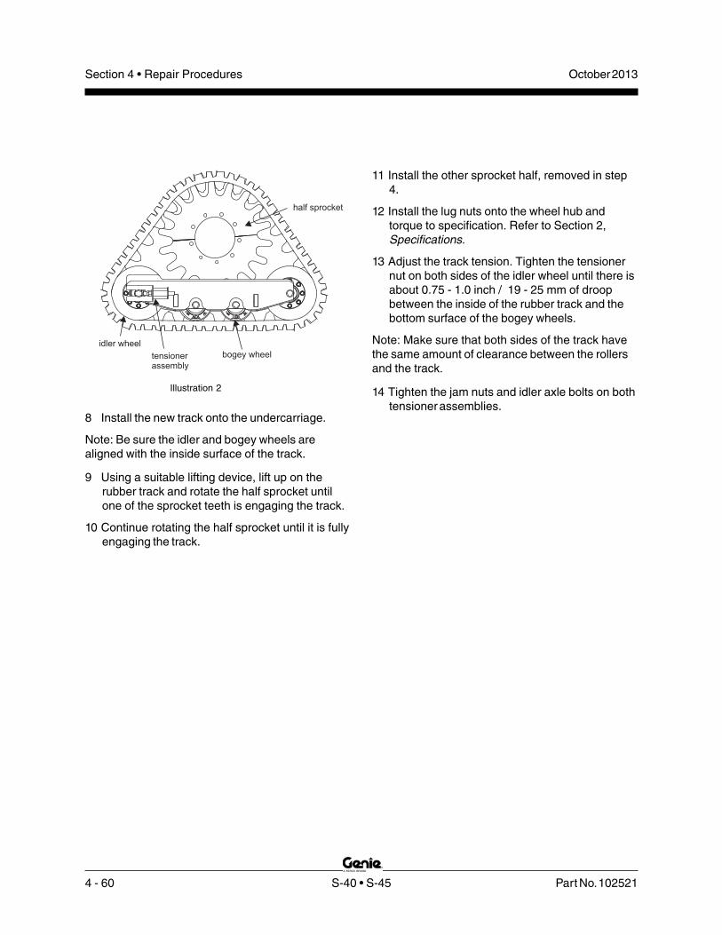
4 - 60 S-40 • S-45 Part No. 102521
October 2013Section 4 • Repair Procedures
8 Install the new track onto the undercarriage.
Note: Be sure the idler and bogey wheels arealigned with the inside surface of the track.
9 Using a suitable lifting device, lift up on therubber track and rotate the half sprocket untilone of the sprocket teeth is engaging the track.
10 Continue rotating the half sprocket until it is fullyengaging the track.
bogey wheeltensioner
assembly
idler wheel
half sprocket
Illustration 2
11 Install the other sprocket half, removed in step4.
12 Install the lug nuts onto the wheel hub andtorque to specification. Refer to Section 2,Specifications.
13 Adjust the track tension. Tighten the tensionernut on both sides of the idler wheel until there isabout 0.75 - 1.0 inch / 19 - 25 mm of droopbetween the inside of the rubber track and thebottom surface of the bogey wheels.
Note: Make sure that both sides of the track havethe same amount of clearance between the rollersand the track.
14 Tighten the jam nuts and idler axle bolts on bothtensioner assemblies.

Part No. 102521 S-40 • S-45 4 - 61
October 2013 Section 4 • Repair Procedures
Generators
11-1Hydraulic Generator
How to Adjust the GeneratorVoltage
Bodily injury hazard. Sprayinghydraulic oil can penetrate andburn skin. Loosen hydraulicconnections very slowly to allowthe oil pressure to dissipategradually. Do not allow oil to squirtor spray.
Electrocution/burn hazard. Contactwith electrically charged circuitscould result in death or seriousinjury. Remove all rings, watchesand other jewelry.
Note: Be sure that the hydraulic oil level is withinthe top 2 inches / 5 cm of the sight gauge.
Note: Perform this procedure with the machine on afirm, level surface.
1 Disconnect all electrical tools from the machine.
2 Start the engine from the platform controls.
3 Press the generator select switch.
4 Connect an electrical tool, which does not drawmore than 15A, to the electrical outlet at theplatform controls and run the tool at full speed.
5 Connect the positive and negative leads from amultimeter of sufficient capacity to the electrical
outlet at the generator.
Result: The reading on the multimeter should be112 to 118V AC.
Result: If the reading on the multimeter is not112 to 118V AC, proceed to step 6.
6 Turn the key switch to the off position.
7 Use a wrench to hold the generator flowregulator valve (item AM) and remove the cap.
a flow regulator
8 Adjust the internal hex socket. Turn it clockwiseto increase the AC voltage or counterclockwiseto decrease the AC voltage. Install the flowregulator valve cap.
Component damage hazard.Failure to adjust the generator asinstructed may result in damage tothe generator or other electricalequipment. Do not adjust thegenerator to other than specified.
9 Repeat steps 2 through 5 to confirm thegenerator AC voltage.
a
4 - 62 S-40 • S-45 Part No. 102521
October 2013Section 4 • Repair Procedures
GENERATORS
How to Purge the Hydraulic Lineon the MTE Generator
Electrocution hazard. Contact withelectrically charged circuits couldresult in death or serious injury.Remove all rings, watches andother jewelry.
Note: This procedure should be performed if thehydaulic line to the generator has been removed.
Note: Perform this procedure with the machine on afirm, level surface.
1 Locate the blue purge wire with the male spadeconnector from the MTE generator harness.
2 Connect a jumper wire of sufficient length fromthe positive battery terminal to the spadeconnector on the purge wire.
3 Start the engine and turn on the generator. Allowthe generator to run for three minutes.
4 Turn off the generator and turn off the engine.
5 Remove the jumper wire from the positivebattery terminal and disconnect from the purgewire.
6 Start the engine and turn on the generator. Usinga digital multimeter check the voltage at theoutlet.
Result: The generator produces a voltage ±10%of rated output. The generator is ready for use.
Result: The generator output voltage is outsidethe ±10% voltage range. Repeat the procedurebeginning with step 2.

Part No. 102521 S-40 • S-45 5 - 1
October 2013 Section 5 • Fault Codes
Before Troubleshooting:
Read, understand and obey the safety rules andoperating instructions printed in theGenie S-40 and S-45 Operator’s Manual.
Be sure that all necessary tools and testequipment are available and ready for use.
Read each appropiate fault code thoroughly.Attempting shortcuts may produce hazardousconditions.
Be aware of the following hazards and followgenerally accepted safe workshop practices.
Crushing hazard. When testingor replacing any hydrauliccomponent, always supportthe structure and secure itfrom movement.
Electrocution/burn hazard. Contactwith electrically charged circuitscould result in death or seriousinjury. Remove all rings, watchesand other jewelry.
Bodily injury hazard. Sprayinghydraulic oil can penetrate andburn skin. Loosen hydraulicconnections very slowly to allowthe oil pressure to dissipategradually. Do not allow oil tosquirt or spray.
Note: Perform all troubleshooting on a firm levelsurface.
Note: Two persons will be required to safelyperform some troubleshooting procedures.
Fault Codes
Observe and Obey:
Troubleshooting and repair procedures shall becompleted by a person trained and qualified onthe repair of this machine.
Immediately tag and remove from service adamaged or malfunctioning machine.
Repair any machine damage or malfunctionbefore operating the machine.
Unless otherwise specified, perform eachrepair procedure with the machine in thefollowing configuration:
• Machine parked on a firm, level surface
• Boom in stowed position
• Turntable rotated with the boom between the non-steer wheels
• Turntable secured with the turntable rotation lock
• Key switch in the off position with the key removed
• Wheels chocked
• All external AC power disconnectedfrom the machine

5 - 2 S-40 • S-45 Part No. 102521
October 2013Section 5 • Fault Codes
FAULT CODES
Fault Code Chart -Control System
How to Retrieve Control SystemFault CodesNote: At least one fault code is present when thealarm at the platform controls produces two shortbeeps every 30 seconds for 10 minutes.
Note: Perform this procedure with the engine off,the key switch turned to platform controls and thered Emergency Stop button pulled out to the onposition at both the ground and platform controls.
1 Open the platform control box lid.
Electrocution/burn hazard. Contactwith electrically charged circuitscould result in death or seriousinjury. Remove all rings, watchesand other jewelry.
2 Locate the red and yellow fault LEDs on theALC-500 circuit board inside the platform controlbox. Do not touch the circuit board.
Component damage hazard.Electrostatic discharge (ESD) candamage printed circuit boardcomponents. If the circuit boarddoes need to be handled, maintainfirm contact with a metal part ofthe machine that is grounded at alltimes when handling the printedcircuit board OR use a groundedwrist strap.
3 Determine the error source: The red LEDindicates the error source and will flash twoseparate codes. The first code will indicate thefirst digit of the two digit code, flashing once persecond. It will then pause for 1.5 seconds andflash the second digit once per 0.5 second.
Note: When the red LED is flashing the code, theyellow LED will be on solid.
4 Determine the error type: The yellow LEDindidates the error type and will flash twoseparate codes. The first code will indicate thefirst digit of the two digit code, flashing once persecond. It will then pause for 1.5 seconds andflash the second digit once per 0.5 second.
Note: When the yellow LED is flashing the code,the red LED will be on solid.
5 Use the fault code table on the following pagesto aid in troubleshooting the machine bypinpointing the area or component affected.

Part No. 102521 S-40 • S-45 5 - 3
October 2013 Section 5 • Fault Codes
Continued on next page
FAULT CODES
Error Source Error Type Condition Solution ID Name ID Name
21 Boom 1 Joystick (primary boom up/ down)
11 12 15 16
Value at 5V Value too high Value too low Value at 0V
Function is inoperative until joystick is calibrated. Alarm sounds indicating fault.
Cycle power off, then on and problem should be corrected.
17 Not calibrated
Function is inoperative until joystick is calibrated.
Calibrate joystick
22 Boom 1 directional valves
21 Fault
Valve is operating outside of operational limits. Alarm sounds indicating fault.
Cycle power off, then on and problem should be corrected.
23
Boom 1 flow control valve
12 15
Value too high Value too low
Valve is operating outside of operational limits. Alarm sounds indicating fault.
Cycle power off, then on and problem should be corrected.
17 Not calibrated
Normal function except threshold for one or both directions is zero.
Calibrate valve thresholds
24
Boom 1 angle sensor
11 12 15 16
Value at 5V Value too high Value too low Value at 0V
Reduced speed. Cycle power off, then on and problem should be corrected.
31 Invalid setup Initiate 1 second beep of alarm.
Calibrate angle sensor.
31 Boom 2 Joystick (secondary boom up/down or primary boom extend/retract)
11 12 15 16
Value at 5V Value too high Value too low Value at 0V
Joystick is operating outside of operational limits. Alarm sounds indicating fault.
Cycle power off, then on and problem should be corrected.
17 Not calibrated
Function is inoperative until joystick is calibrated.
Calibrate joystick
32 Boom 2 directional valves
21 Fault
Valve is operating outside of operational limits. Alarm sounds indicating fault.
Cycle power off, then on and problem should be corrected.

5 - 4 S-40 • S-45 Part No. 102521
October 2013Section 5 • Fault Codes
FAULT CODES
Error Source Error Type ID Name ID Name
Condition Solution
12 15
Value too high Value too low
Valve is operating outside of operational limits. Alarm sounds indicating fault.
Cycle power off, then on and problem should be corrected.
33 Boom 2 flow control valve
17 Not calibrated
Normal function except threshold for one or both directions is zero.
Calibrate valve thresholds
11 12 15 16
Value at 5V Value too high Value too low Value at 0V
Joystick is operating outside of operational limits. Alarm sounds indicating fault.
Cycle power off, then on and problem should be corrected.
41 Turntable rotate joystick
17 Not calibrated Function is inoperative until joystick is calibrated.
Calibrate joystick
42 Turntable rotate directional valves
21 Fault
Valve is operating outside of operational limits. Alarm sounds indicating fault.
Cycle power off, then on and problem should be corrected.
12 15
Value too high Value too low
Valve is operating outside of operational limits. Alarm sounds indicating fault.
Cycle power off, then on and problem should be corrected.
43 Turntable rotate flow control valve
17 Not calibrated
Normal function except threshold for one or both directions is zero.
Calibrate valve thresholds.
44 Drive enable toggle switch
21 Fault
Drive enable function is inoperative.
Cycle power off, then on and problem should be corrected.
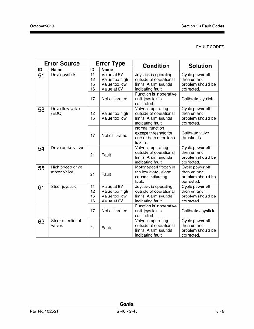
Part No. 102521 S-40 • S-45 5 - 5
October 2013 Section 5 • Fault Codes
FAULT CODES
Error Source Error Type ID Name ID Name
Condition Solution 11 12 15 16
Value at 5V Value too high Value too low Value at 0V
Joystick is operating outside of operational limits. Alarm sounds indicating fault.
Cycle power off, then on and problem should be corrected.
51 Drive joystick
17 Not calibrated Function is inoperative until joystick is calibrated.
Calibrate joystick
12 15
Value too high Value too low
Valve is operating outside of operational limits. Alarm sounds indicating fault.
Cycle power off, then on and problem should be corrected.
53 Drive flow valve (EDC)
17 Not calibrated
Normal function except threshold for one or both directions is zero.
Calibrate valve thresholds
54 Drive brake valve
21 Fault
Valve is operating outside of operational limits. Alarm sounds indicating fault.
Cycle power off, then on and problem should be corrected.
55 High speed drive motor Valve 21 Fault
Motor speed frozen in the low state. Alarm sounds indicating fault.
Cycle power off, then on and problem should be corrected.
11 12 15 16
Value at 5V Value too high Value too low Value at 0V
Joystick is operating outside of operational limits. Alarm sounds indicating fault.
Cycle power off, then on and problem should be corrected.
61 Steer joystick
17 Not calibrated Function is inoperative until joystick is calibrated.
Calibrate Joystick
62 Steer directional valves
21 Fault
Valve is operating outside of operational limits. Alarm sounds indicating fault.
Cycle power off, then on and problem should be corrected.

5 - 6 S-40 • S-45 Part No. 102521
October 2013Section 5 • Fault Codes
FAULT CODES
Ford LRG-425 EFI Engine
How to Retrieve Ford EngineFault CodesThe ECM constantly monitors the engine by theuse of sensors on the engine. The ECM also usessignals from the sensors to initiate sequential fuelinjection and make constant and instantaneouschanges to ignition timing, fuel delivery and throttleposition to maintain the engine's running conditionat its highest efficiency while at the same timekeeping exhaust emissions to a minimum. When asensor fails or returns signals that are outside ofset parameters, the ECM will store a fault code inmemory that relates to the appropriate sensor andwill turn on the Check Engine Light.
Note: Perform this procedure with the key switch inthe off position.
1 Open the ground controls side cover and locatethe run/test toggle switch on the side of theground control box.
2 Pull out the red Emergency Stop button to theon position at both the ground and platformcontrols.
3 Quickly activate and release the start toggleswitch/button. Do not start the engine.
4 Move and hold the run/test toggle switch to thetest position.
Result: The check engine light should turn on.The check engine light should begin to blink.
5 Continue to hold the run/test toggle switch in thetest position and count the blinks.
Note: Before the fault codes are displayed, thecheck engine light will blink a code 123 three times.After the fault codes, the check engine light willblink a code 123 three times again indicating theend of the stored codes.
Note: If any fault codes are present, the ECM willblink a three digit code three times for each codestored in memory. It will blink the first digit of athree digit code, pause, blink the second digit,pause, and then blink the third digit. For example:the check engine light blinks 5 consecutive times,blinks 3 times and then 1 time. That would indicatecode 531.
Note: Once a fault code has been retrieved and therepair has been completed, the ECM memory mustbe reset to clear the fault code from the ECM. SeeHow to Clear Engine Fault Codes from the ECM.
How to Clear Engine FaultCodes from the ECMNote: Perform this procedure with the engine offand the key switch in the off position.
1 Open the engine side turntable cover and locatethe battery.
2 Disconnect the negative battery cable from thebattery for a minimum of 5 minutes.
Electrocution/burn hazard. Contactwith electrically charged circuitscould result in death or seriousinjury. Remove all rings, watchesand other jewelry.
3 Connect the negative battery cable to thebattery.

Part No. 102521 S-40 • S-45 5 - 7
October 2013 Section 5 • Fault Codes
FAULT CODES
Code Problem Cause Solution
111
112
113
114
121
122
124
133
134
135
141
142
143
144
Closed Loop MultiplierHigh (LPG)
HO2S Open/Inactive(Bank 1)
HO2S Open/Inactive(Bank 2)
Post-cat oxygensensor open
Closed Loop MultiplierHigh (Gasoline)
Closed Loop MultiplierLow (Gasoline)
Closed Loop MultiplierLow (LPG)
Gasoline cat monitor
LPG cat monitor
NG cat monitor
Adaptive Lean Fault -High Limit (Gasoline)
Adaptive Rich Fault -Low Limit (Gasoline)
Adaptive Learn High(LPG)
Adaptive Learn Low(LPG)
Heated Oxygen Sensor wiring and/orconnections open or shorted OR sensor is faultyOR there are vacuum leaks or exhaust leaks.
Heated Oxygen Sensor wiring and/or connectionsopen or shorted OR sensor is faulty.
The post cat Heated Oxygen Sensor wiringand/or connections are open or shorted ORsensor is cold, non-responsive or inactive for60 seconds or longer.
Heated Oxygen Sensor wiring and/orconnections open or shorted OR sensor isfaulty OR there are vacuum leaks or exhaustleaks OR fuel pressure is low OR the fuelinjectors need cleaning or replacing.
MAP, IAT or ECT sensors not in correct positionOR wiring and/or connections for sensors openor shorted OR sensor is faulty OR one or morefuel injectors are stuck open OR there iselectro-magnetic interference from a faultycrankshaft and/or camshaft position sensor.
Heated Oxygen Sensor wiring and/orconnections open or shorted OR sensor isfaulty OR fuel quality is poor OR fuel systemcomponents may be faulty.
There are exhaust leaks OR the catalyst systemefficiency is below the acceptable level.
Heated Oxygen Sensor wiring and/orconnections open or shorted OR sensor isfaulty OR there are vacuum or exhaust leaksOR one or more fuel injectors faulty or stuckclosed OR fuel quality is poor OR fuelpressure is too low.
MAP, IAT or ECT sensors not in correct positionOR wiring and/or connections for sensors openor shorted OR sensor is faulty OR one or morefuel injectors are stuck closed OR there iselectro-magnetic interference from a faultycrankshaft and/or camshaft position sensor.
Heated Oxygen Sensor wiring and/orconnections open or shorted OR sensor isfaulty OR there are vacuum leaks or exhaustleaks OR fuel quality is poor OR fuel systemcomponents may be faulty.
Engine wire harness may have an intermittentshort to 5V DC or 12V DC OR fuel systemcomponents may be faulty.
Heated Oxygen Sensor wiring and/or connectionsopen or shorted OR sensor is faulty.
Repair wiring and/or connections OR replacesensor OR repair vacuum and exhaust leaks.
Repair wiring and/or connections ORreplace sensor.
Repair wiring and/or connections OR replacethe post cat oxygen sensor.
Repair wiring and/or connections OR replacesensor OR repair any vacuum and exhaust leaksOR test the fuel pressure OR clean or replace thefuel injectors.
Adjust or replace sensors OR clean or repairfuel injectors.
Repair wiring and/or connections OR replacesensor OR replace fuel OR test and repair thefuel system components.
Repair exhaust leaks OR there is an emissionscompliance issue. Contact Ford Power Productsfor assistance.
Repair heated oxygen sensor wiring and/orconnections OR replace sensor OR repairvacuum and exhaust leaks OR test the fuelpressure OR clean or replace the fuel injectors.
Repair wiring and/or connections OR replacesensor OR repair any vacuum and exhaustleaks OR replace fuel OR test and repair thefuel system components.
Repair short in engine wire harnessOR test and repair the fuel systemcomponents.
Adjust or replace sensors OR clean or repairfuel injectors.

5 - 8 S-40 • S-45 Part No. 102521
October 2013Section 5 • Fault Codes
FAULT CODES
Code Problem Cause Solution
242 Crank Sync NoiseCrankshaft position sensor wiring and/orconnections open or shorted OR there is a poorsystem ground connection OR sensor is faulty.
235 BP Low Pressure MAP sensor is faulty OR ECM is faulty.
234 BP High Pressure MAP sensor is faulty OR ECM is faulty.
232 MAP Low VoltageOpen or shorted wiring and/or connections to MAPsensor OR sensor is faulty.
231 MAP High PressureOpen or shorted wiring and/or connections to MAPsensor OR sensor is faulty.
215 Oil Pressure LowFaulty oil pressure sensor OR sensor wiringand/or connections open or shorted OR engineoil level too low.
Replace oil pressure sensor OR repair sensorwiring and/or connections OR fill engine oil levelto specification.
214IAT Higher ThanExpected (2)
Air intake temperature is greater than 210 F withthe engine greater than 1000 rpm OR air intakesystem has leaks OR IAT sensor is faulty.
°
213IAT Higher ThanExpected (1)
Air intake temperature is greater than 200 F withthe engine greater than 1000 rpm OR air intakesystem has leaks OR IAT sensor is faulty.
°
212 IAT Low VoltageIAT sensor wiring and/or connections are open orshorted OR sensor is faulty OR engine intake airtemperature is too hot.
Repair wiring and/or connections OR replacesensor OR direct cooler air into air intake.
224CHT Higher ThanExpected (2)
Coolant temperature at the cylinder head is 250 F.Engine cooling system is malfunctioning andoverheating the engine OR sensor wires and/orconnections open or shorted OR sensor is faultyOR coolant level is low.
°
223CHT Higher ThanExpected (1)
Coolant temperature at the cylinder head is 240 F.Engine cooling system is malfunctioning andoverheating the engine OR sensor wires and/orconnections open or shorted OR sensor is faultyOR coolant level is low.
°Repair engine cooling system problems ORrepair open or shorted wiring to sensor ORreplace sensor OR fill engine coolant level tospecification.
222 CHT/ECT Low Voltage
Engine cooling system is malfunctioning andoverheating the engine OR sensor wires and/orconnections open or shorted OR sensor is faultyOR coolant level is low.
221 CHT/ECT High VoltageEngine cooling system is malfunctioning ORsensor wires and/or connections open or shortedOR sensor is faulty.
Repair engine cooling system problems ORrepair open or shorted wiring to sensor ORreplace sensor.
211 IAT High VoltageIAT sensor wiring and/or connections are open orshorted OR sensor is faulty OR engine intake airtemperature is too cold.
Repair wiring and/or connections OR replacesensor OR direct warmer air into air intake.
162 System Voltage HighAlternator is overcharging the battery whenengine RPM is greater than 1500 rpm.
Repair or replace the alternator.
161 System Voltage LowBattery is faulty OR alternator is not charging ORbattery supply wiring to ECM is open or shorted.
Replace battery OR repair alternator OR repairbattery supply wiring to ECM.
Camshaft Sensor Loss244Crankshaft position sensor wiring and/orconnections open or shorted OR there is a poorsystem ground connection OR sensor is faulty.
243Never Crank SyncedAt Start
Crankshaft position sensor wiring and/orconnections open or shorted OR there is a poorsystem ground connection OR sensor is faulty.
Be sure system ground connections are in placeand secure OR repair wiring and/or connectionsto sensor OR replace sensor.
Check air intake system for damage and properrouting of air intake components OR replace theIAT sensor.
Repair wiring and/or connections to sensor ORreplace MAP sensor.
Replace MAP sensor OR replace the ECM.

Part No. 102521 S-40 • S-45 5 - 9
October 2013 Section 5 • Fault Codes
FAULT CODES
Code Problem Cause Solution
253 Knock Sensor OpenKnock sensor wiring and/or connections open orshorted OR sensor is faulty.
Repair wiring and/or connections to knock sensorOR replace knock sensor.
Camshaft Sensor Noise
Camshaft position sensor wiring and/orconnections open or shorted OR there is a poorsystem ground connection OR sensor is faulty.
245Be sure system ground connections are in placeand secure OR repair wiring and/or connectionsto sensor OR replace sensor.
Excessive Knock SignalKnock sensor wiring and/or connections open orshorted OR there is excessive engine vibrationOR sensor is faulty.
254Check for excessive engine vibration OR repairwiring and/or connections to knock sensor ORreplace knock sensor.
Injector Driver #1 OpenOpen wiring and/or connections to fuel injector #1OR fuel injector #1 is faulty OR ECM is faulty.311
Repair wiring and/or connections to fuel injector #1OR replace fuel injector #1 OR replace the ECM.
Injector Driver #1 ShortedWiring and/or connections to fuel injector #1 isshorted OR fuel injector #1 is faulty ORECM is faulty.
312
Injector Driver #2 OpenOpen wiring and/or connections to fuel injector #2OR fuel injector #2 is faulty OR ECM is faulty.313
Repair wiring and/or connections to fuel injector #2OR replace fuel injector #2 OR replace the ECM.
Injector Driver #2 ShortedWiring and/or connections to fuel injector #2 isshorted OR fuel injector #2 is faulty ORECM is faulty.
314
Injector Driver #3 OpenOpen wiring and/or connections to fuel injector #3OR fuel injector #3 is faulty OR ECM is faulty.315
Repair wiring and/or connections to fuel injector #3OR replace fuel injector #3 OR replace the ECM.
Injector Driver #3 ShortedWiring and/or connections to fuel injector #3 isshorted OR fuel injector #3 is faulty ORECM is faulty.
316
Injector Driver #4 OpenOpen wiring and/or connections to fuel injector #4OR fuel injector #4 is faulty OR ECM is faulty.321
Repair wiring and/or connections to fuel injector #4OR replace fuel injector #4 OR replace the ECM.
Injector Driver #4 ShortedWiring and/or connections to fuel injector #4 isshorted OR fuel injector #4 is faulty ORECM is faulty.
322
Fuel Pump Loop Open orHigh Side Short to Ground
Open wiring and/or connections to fuel pump ORfuel pump power shorted to ground OR fuel pumpis faulty.
351Repair wiring and/or connections to fuel pump ORreplace fuel pump.
Wiring and/or connections to fuel pump shorted topower OR fuel pump is faulty.352
Fuel Pump High SideShorted to Power
Fuel pressure too high OR LPG lockoff not openingcompletely OR the line between the MegaJectorand carburetor is kinked or restricted or is leakingOR engine cooling system is not operating properlyOR MegaJector is faulty.
353MegaJector DeliveryPressure Higher ThanExpected Check fuel pressure OR repair LPG lockoff OR
repair the line between the MegaJector andcarburetor OR repair engine cooling system ORreplace the MegaJector.
Fuel pressure too low OR LPG lockoff not openingcompletely OR the line between the MegaJectorand carburetor is kinked or restricted or is leakingOR engine cooling system is not operating properlyOR MegaJector is faulty.
354MegaJector DeliveryPressure Lower ThanExpected
The ECM doesn't get any response from theMegaJector, or an incorrect response for 500msperiod or longer.
355MegaJectorCommunication Lost
Check CAN circuits for continuity and shorts topower or ground and for continuity and repair asnecessary OR replace the MegaJector.
The MegaJector detects voltage greater than 18volts for 5 seconds anytime the engine is crankingor running.
361MegaJector VoltageSupply High
Repair charging system OR replace theMegaJector.
The MegaJector detects voltage less than 9.5 voltsfor 5 seconds anytime the engine is cranking orrunning.
362Repair VBAT power or ground circuit to ECM andMegaJector OR replace battery OR repaircharging system OR replace the MegaJector.
MegaJector VoltageSupply Low

5 - 10 S-40 • S-45 Part No. 102521
October 2013Section 5 • Fault Codes
FAULT CODES
Code Problem Cause Solution
MegaJector InternalActuator Fault Detection
The MegaJector detects an internal fault. Open orshort in power, ground or CAN circuits.363
Check Power, Ground and CAN circuits atMegaJector and all connections and repair asnecessary OR MegaJector has an internal fault.Contact Ford Power Products for assistance.
MegaJector InternalCircuitry Fault Detection
The MegaJector detects an internal circuitry failure.Open or short in power, ground or CAN circuits.364
MegaJector InternalCommunication FaultDetection
The MegaJector detects an internalcommunications failure. Open or short in power,ground or CAN circuits.
365
Open wiring and/or connections to ignitioncoil #1 OR ignition coil #1 is faulty.
Repair wiring and/or connections to ignitioncoil #1 OR replace ignition coil #1.
Coil Driver #1 Open411
Wiring and/or connections to ignition coil #1shorted OR ignition coil #1 is faulty
Coil Driver #1 Shorted412
Open wiring and/or connections to ignitioncoil #2 OR ignition coil #2 is faulty.
Repair wiring and/or connections to ignitioncoil #2 OR replace ignition coil #2.
Coil Driver #2 Open413
Wiring and/or connections to ignition coil #2shorted OR ignition coil #2 is faulty
Coil Driver #2 Shorted414
Not used.
FPP1 High Voltage511
If this fault appears on your machine, contactthe Genie Industries Service Department.
512 FPP1 Low Voltage
513 FPP1 Higher than IVS Limit
514
521 FPP2 High Voltage
FPP1 Lower than IVS Limit
522 FPP2 High Voltage
The #1 throttle position sensor wiring and/orconnections open or shorted OR there is a poorsystem ground connection OR throttle positionsensor #1 is faulty.
531 TPS1 (Signal Voltage) HighBe sure system ground connections are in placeand secure OR repair wiring and/or connectionsto sensor OR replace throttle position sensor #1.
532 TPS1 (Signal Voltage) Low
The #2 throttle position sensor wiring and/orconnections open or shorted OR there is a poorsystem ground connection OR throttle positionsensor #2 is faulty.
533 TPS2 (Signal Voltage) HighBe sure system ground connections are in placeand secure OR repair wiring and/or connectionsto sensor OR replace throttle position sensor #2.
534 TPS2 (Signal Voltage) Low
The throttle position sensor wiring and/orconnections for either TPS1 or TPS2 open orshorted OR there is a poor system groundconnection OR one or both throttle positionsensors are faulty.
TPS1 Higher than TPS2535
536 TPS1 Lower than TPS2
Be sure engine harness wiring and connectionsare in place and secure OR repair wiring and/orconnections to one or both TPS sensors ORreplace one or both TPS sensors.
Governor actuator is stuck closed OR wiringand/or connections open or shorted ORgovernor actuator is faulty.
Throttle Unable to Open537Repair wiring and/or connections to governoractuator OR replace the governor actuator.
Governor actuator is stuck open OR wiringand/or connections open or shorted ORgovernor actuator is faulty.
Throttle Unable to Close538
Engine harness wiring and/or connections openor shorted OR there is a poor system groundconnection OR ECM is faulty.
Governor Interlock Failure545Repair wiring and/or connections in engineharness OR replace the ECM.

Part No. 102521 S-40 • S-45 5 - 11
October 2013 Section 5 • Fault Codes
FAULT CODES
Code Problem Cause Solution
ECM needs to be re-programmed OR throttle issticking open OR there are air leaks between thethrottle body and cylinder head.
Max Governor SpeedOverride
Re-program ECM OR repair binding throttleoperation OR repair any air leaks between thethrottle body and cylinder head.
551
552 FPP1 Low Voltage
553 FPP1 Higher than IVS Limit
Loose wire connections to ECM OR ECM is faulty.
COP Failure611
Locate and repair any engine harness wiringdamage or shorts to ECM to be sure they aresecure OR replace ECM.
612 Invalid Interrupt
613 A/D Loss
614
615 Flash Checksum Invalid
RTI 1 Loss
616 RAM Failure
Locate and repair any engine harness wiringdamage or shorts OR locate and troubleshoot orrepair faulty engine sensor OR replace ECM.
External 5V DC RefLower than Expected Engine harness wiring and/or connections open
or shorted to ground OR there is a faulty enginesensor OR ECM is faulty.
631
632External 5V DC RefHigher than Expected
Locate and repair any engine harness wiringdamage or shorts to ECM to be sure they aresecure OR replace ECM.
RTI2 Loss655
656 RTI3 Loss
Loose wire connections to ECM OR ECM is faulty.

5 - 12 S-40 • S-45 Part No. 102521
October 2013Section 5 • Fault Codes
FAULT CODES
Ford DSG-423 EFI Engine
How to Retrieve Ford EngineFault CodesThe ECM constantly monitors the engine by theuse of sensors on the engine. The ECM alsouses signals from the sensors to initiatesequential fuel injection and make constant andinstantaneous changes to ignition timing, fueldelivery and throttle position to maintain theengine's running condition at its highest efficiencywhile at the same time keeping exhaustemissions to a minimum. When a sensor fails orreturns signals that are outside of setparameters, the ECM will store a fault code inmemory that relates to the appropriate sensorand will turn on the Check Engine Light.
Note: Perform this procedure with the key switchin the off position.
1 Open the ground controls side cover andlocate the run/test toggle switch on the side ofthe ground control box.
2 Pull out the red Emergency Stop button to theon position at both the ground and platformcontrols.
3 Quickly activate and release the start toggleswitch/button. Do not start the engine.
4 Move and hold the run/test toggle switch tothe test position.
Result: The check engine light should turn on.The check engine light should begin to blink.
5 Continue to hold the run/test toggle switch inthe test position and count the blinks.
Note: Before the fault codes are displayed, thecheck engine light will blink a code 123 threetimes. After the fault codes, the check enginelight will blink a code 123 three times againindicating the end of the stored codes.
Note: If any fault codes are present, the ECM willblink a three digit code three times for each codestored in memory. It will blink the first digit of athree digit code, pause, blink the second digit,pause, and then blink the third digit. For example:the check engine light blinks 5 consecutivetimes, blinks 3 times and then 1 time. That wouldindicate code 531.
Note: Once a fault code has been retrieved andthe repair has been completed, the ECM memorymust be reset to clear the fault code from theECM. See How to Clear Engine Fault Codes fromthe ECM.
How to Clear Engine FaultCodes from the ECMNote: Perform this procedure with the engine offand the key switch in the off position.
1 Open the engine side turntable cover andlocate the battery.
2 Disconnect the negative battery cable fromthe battery for a minimum of 5 minutes.
Electrocution/burn hazard.Contact with electrically chargedcircuits could result in death orserious injury. Remove all rings,watches and other jewelry.
3 Connect the negative battery cable to thebattery.
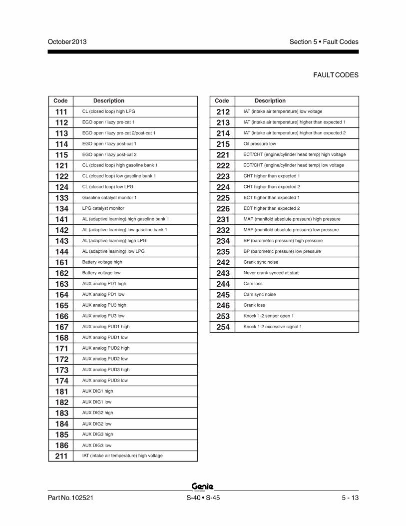
Part No. 102521 S-40 • S-45 5 - 13
October 2013 Section 5 • Fault Codes
FAULT CODES
Code Description
212
213
214
215 Oil pressure low
222
223
224
CHT higher than expected 1
225
IAT (intake air temperature) low voltage
IAT (intake air temperature) higher than expected 1
IAT (intake air temperature) higher than expected 2
221 ECT/CHT (engine/cylinder head temp) high voltage
ECT/CHT (engine/cylinder head temp) low voltage
CHT higher than expected 2
ECT higher than expected 1
226
231
232
MAP (manifold absolute pressure) high pressure
234
ECT higher than expected 2
MAP (manifold absolute pressure) low pressure
BP (barometric pressure) high pressure
235
242
243
Crank sync noise
244
Never crank synced at start
Cam loss
BP (barometric pressure) low pressure
245
246
253
Crank loss
254
Knock 1-2 sensor open 1
Cam sync noise
Knock 1-2 excessive signal 1
Code Description
111 CL (closed loop) high LPG
112 EGO open / lazy pre-cat 1
113
114 EGO open / lazy post-cat 1
EGO open / lazy pre-cat 2/post-cat 1
115
121
122
124
EGO open / lazy post-cat 2
CL (closed loop) high gasoline bank 1
CL (closed loop) low gasoline bank 1
CL (closed loop) low LPG
133
134
141
142
Gasoline catalyst monitor 1
LPG catalyst monitor
AL (adaptive learning) high gasoline bank 1
AL (adaptive learning) low gasoline bank 1
143
144
161
162
Battery voltage high
AL (adaptive learning) high LPG
AL (adaptive learning) low LPG
Battery voltage low
163
164
165
166
AUX analog PD1 high
AUX analog PD1 low
AUX analog PU3 high
AUX analog PU3 low
167
168
171
172
AUX analog PUD1 high
AUX analog PUD1 low
AUX analog PUD2 high
AUX analog PUD2 low
173
174
181
182
AUX analog PUD3 high
AUX analog PUD3 low
AUX DIG1 high
AUX DIG1 low
183
184
185
186
211 IAT (intake air temperature) high voltage
AUX DIG2 high
AUX DIG2 low
AUX DIG3 high
AUX DIG3 low

5 - 14 S-40 • S-45 Part No. 102521
October 2013Section 5 • Fault Codes
FAULT CODES
Code Description
261 FP (fuel pressure) high voltage
262
271
272
FT (fuel temperature) gasoline high voltage
273
274
311
312
Injector loop open OR low-side short to ground 1
313
314
315
316
Injector loop open OR low-side short to ground 2
Injector coil shorted 2
Injector loop open OR low-side short to ground 3
Injector coil shorted 3
321
322
351
352
FPump motor loop open OR high-side shorted to ground
Injector loop open OR low-side short to ground 4
Injector coil shorted 4
Fpump motor high-side shorted to power
353
354
355
359
EPR delivery pressure higher than expected
EPR delivery pressure lower than expected
EPR comm lost
Fuel run-out longer than expected
361
362
363
364
EPR voltage supply high
EPR voltage supply low
EPR internal actuator fault detection
EPR internal circuitry fault detection
365
411
412
413
EPR internal comm fault detection
Primary loop open OR low-side short to ground 1
Primary coil shorted 1
Primary loop open OR low-side short to ground 2
414
415
416
421
422 Primary coil shorted 4
Primary coil shorted 2
Primary loop open OR low-side short to ground 3
Primary coil shorted 3
Primary loop open OR low-side short to ground 4
FP (fuel pressure) low voltage
FT (fuel temperature) gasoline low voltage
FT (fuel temperature) gaseous fuel high voltage
FT (fuel temperature) gaseous fuel low voltage
Injector coil shorted 1
Code Description
531
532
533
534
536
537
538
Unable to reach higher TPS (throttle position sensor)
539
TPS1 (throttle position sensor) high voltage
535 TPS1 (throttle position sensor) higher than TPS2
TPS1 (throttle position sensor) lower than TPS2
Unable to reach lower TPS (throttle position sensor)
TPS 1-2 simultaneous voltages
541
542
543
544
AUX analog PU1 high
551
552
553
Fuel rev limit
611
Spark rev limit
COP failure
Max govern speed override
612
613
614
A/D loss
615
RTI 1 loss
Invalid interrupt
Flash checksum invalid
TPS1 (throttle position sensor) low voltage
TPS2 (throttle position sensor) high voltage
TPS2 (throttle position sensor) low voltage
AUX analog PU1 low
AUX analog PU2 high
AUX analog PU2 low

Part No. 102521 S-40 • S-45 5 - 15
October 2013 Section 5 • Fault Codes
FAULT CODES
For further engine fault code troubleshooting anddiagnostic information, refer to the Ford DSG-423EFI Service Manual (EDI part number 1060040).Genie part number 119494.
Ford DSG 423 EFI Operator HandbookGenie part number 119488
Code Description
744
761
762
763
772
1629
1630
J1939 TSC1 message receipt lost
PWM5 short to power
771 Tach output ground short
Tach output short to power
J1939 ETC message receipt lost
MIL (malfunction indicator light) control ground short
MIL (malfunction indicator light) open
MIL (malfunction indicator light) control short to power
Code Description
616 RAM failure
631
632
633
5VE1 high voltage
634
635
641
642
Rx inactive
643
644
646
647
Invalid packet format
Shutdown request
CAN Tx failure
CAN Rx failure
648
655
656
711
RTI 3 loss
CAN address conflict failure
RTI 2 loss
Relay control ground short
712
713
714
715
Relay coil open
Relay coil short to power
Fpump relay control ground short
Fpump relay coil open
716
721
722
723
Fpump relay coil short to power
Start relay control ground short
Start relay coil open
Start relay coil short to power
731
732
733
734
PWM1-gauge1 open / ground short
PWM1-gauge1 short to power
735
736
741
742
743
5VE1 low voltage
5VE1-5VE2 simultaneous out-of-range
Rx noise
5VE2 high voltage
5VE2 low voltage
PWM2-gauge2 open / ground short
PWM2-gauge2 short to power
PWM3-gauge3 open / ground short
PWM3-gauge3 short to power
PWM4 open / ground short
PWM4 short to power
PWM5 open / ground short

5 - 16 S-40 • S-45 Part No. 102521
October 2013Section 5 • Fault Codes
This page intentionally left blank.

Part No. 102521 S-40 • S-45 6 - 1
Observe and Obey:
Troubleshooting and repair procedures shall becompleted by a person trained and qualified onthe repair of this machine.
Immediately tag and remove from service adamaged or malfunctioning machine.
Repair any machine damage or malfunctionbefore operating the machine.
Before Troubleshooting:
Read, understand and obey the safety rulesand operating instructions printed in theGenie S-40 & Genie S-45 Operator's Manual.
Be sure that all necessary tools and testequipment are available and ready for use.
About This SectionThere are two groups of schematics in this section.An illustration legend precedes each group ofdrawings.
Electrical Schematics
Electrocution/burn hazard. Contactwith electrically charged circuitscould result in death or seriousinjury. Remove all rings, watchesand other jewelry.
Hydraulic Schematics
Bodily injury hazard. Sprayinghydraulic oil can penetrate andburn skin. Loosen hydraulicconnections very slowly to allowthe oil pressure to dissipategradually. Do not allow oil to squirtor spray.
General Repair Process
Malfunctiondiscovered
Identifysymptoms
Troubleshoot
Performrepair
Return toservice problem
solved
problemstill exists
Inspectand test
Schematics
October 2013 Section 6 • Schematics

6 - 2 S-40 • S-45 Part No. 102521
Connectionno terminal
P3
Horn buttonnormally open
T-circuitsconnect
FB
Flashing beacon
Diode
Circuits crossingno connection
Quick disconnectterminal
BLK
WHT
T-circuits connectat terminal
WHT #21 TB21
Battery
+
-
Circuit breakerwith amperage
15A
CB1
Horn or alarm
H1 Emergency Stopbutton normally
closed
P1
Coilsolenoid or relay
Key switch(before serial number 22051)
KS1
GROUND
PLATFORM
Power relay
PR1
Toggle switch SPDT
TS2
START
EN
GIN
E
Toggle switch DPDT
TS6
UP
DO
WN
PLATFO
RM
LEV
EL
Gauge sending unit
HM
Hour meter
N.O.OTS2
Oil temperatureswitch
normally open
N.O.CTS1
Coolant temperatureswitch
normally open
Oil pressure switchnormally closed
N.C.OPS1
BLK
FS1
Foot switch
PumpAux
Auxiliary pump
FAN
Hydraulic oilcooling fan
G1
Gauge
Tilt sensorLED
L3
Limit switch
N.C.H.ON.O.H.C
LS3
Fusewith amperage
25A
F1
510
Resistor withohm value
Starting aid:glow plug orflame ignitor
Control relay contactnormally open
CR4N.O.
Coil
Fuel or RPMsolenoid
PU
LL
IN
HO
LD
CA B
Key switch(after serial number 22050)
KS1
October 2013Section 6 • Schematics
Electrical Symbols Legend

Part No. 102521 S-40 • S-45 6 - 3
October 2013 Section 6 • Schematics
Hydraulic Symbols Legend
Pumpfixed displacement
Motorbi-directional
Check valve
2 position, 3 way, shuttle valve
Double actingcylinder
Priorityflow regulator valve
Differentialsensing valve
Solenoid operatedproportional valve
Brake
Pilot operated 3 position,3 way, shuttle valve
Filter withbypass valverelief setting
25 psi(1.7 bar)
Motor2-speed,
bi-directional
Pumpbi-directional,
variable displacement
E
Pump prime mover(engine or motor)
Directional valve(mechanically activated)
o
Relief valvewith pressure setting
200 psi(13.8 bar)
Orifice with size
.035"(0.89 mm)
Solenoid operated 3 position,4 way, directional valve
Directional valvepilot operated
2 position, 2 way
Flow divider/combiner valvewith pressure balancing orifice
and flow percentages
50% 50%
Counterbalance valvewith pressure and pilot ratio
(206.8 bar)3000 psi
3:1
Solenoid operated 2 position,3 way, directional valve
2 position, 2 waysolenoid valve
Solenoid operated3 position, 4 way,
proportional directional valve
Needle valve

6 - 4 S-40 • S-45 Part No. 102521
October 2013Section 6 • Schematics
Power
Relay
Starter
Relay
Fuel
Pump
Relay
F5-15A
F4-15AF3-10A
F2-5AF1-10A
Empty
Ford DSG-423 Engine Relay Layout
F6-10A
F6-10A

1
2
3
4
5
6
7
8
N M L K J I H G F E D C B A
Part No. 102521 S-40 • S-45 6 - 5
October 2013 Section 6 • Schematics
Connector Pin Legend
1
2
3
5
6
4
CKT # PIN #
9
8
10
12
11
7
GR/BK
GR/WH
GR
PLUG
PLUG
PLUG
C43HRN
C45GEN
PLUG
PLUG
JDALARM
C2P DT06-12SB
OR/RD
COLOR
OR/BK
BL/RD
OR C40LS1
C41RPM
C39LP
3
2
4
5
CKT # PIN #
7
8
9
10
12
6
C30EDC+WH
WH/BK
BK/WH
BK/RD
BL/BK
BL/WH
WH/RD
BL
BK
C35RPM
C36STC
C37STCC 11
C31EDC-
C33STR
C34SA
C32BRK
COLOR
RD/WH
RD/BK
RD C27AUX
C28TTA
C29MS
1
C1P DT06-12SA
GR/BK
GR/WH
11PLUG
PLUG 12
PLUG
PLUG
PLUG
C18JD
C19JSV
8
10
9
7
6
C14PLU
C15PLD
C13DRE
C17JU
C4P DT06-12SD
OR/BK
GR/BK
GR
BL/RD
OR
COLOR
3
4
5
2
1
CKT # PIN #
CKT # PIN #
3C3PBFRD/WH
WH/BK
BK/WH
GR/BK
BL/WH
WH/RD
BL/BK
BL
BK
WH
8C8PBR
JALARM
C11SBD
C12SBF
C10SBU
11
12
10
9
C7PBE
C6TRF
C4TRL
C5TRR
7
6
4
5
C3P DT06-12SC
COLOR
RD/BK
RD C1PBU
C2PBD 2
1
RD/BK
WH/RD
BL/WH
BL/BK
GR/WH
38
39
40
C45GEN
C40LS1 OR
35
37
36
34
33
30
32
31
29
28
R116HYD
C36STC
C37STCC
R21IGN
BL
WH
OR
P46PWR
C32TA
C28TTA
COLOR
RD/BK
WH/BK
RD/WH
BK/WH
WH/RD
BL/RD
GR/BK
OR/BK
RD/BK
C6TRF6
22
25
26
27
24
23
21
20
18
19
17
C116HYD
C134PWR
C27AUX
GND
BK
BR
RD
RD
C18JD
C17JU
C2DA
GR
11
14
15
16
13
12
10
9
7
8
C14PLU
C13DRE
C15PLD
R43HRN
OR
BK
C8PBR
C7PBE BK
3
5
4
2
1
C3PBF
C4TRL
C5TRR
C2PBD
C1PBU
WH
RD
CIRCUIT # CIRCUIT # COLOR
C1PBU
C2PBD
C5TRR
C4TRL
C3PBF
C7PBE
C8PBR
C6TRF WH/RD
BK/WH
BK
RD/WH
WH/BK
RD/BK
WH
RD
R43HRN
C15PLD
C13DRE
C14PLU
C2DA
C17JU
C18JD
RD/BK
GR/BK
OR/BK
BL/RD
BK
GR
OR
RDC23BAT
C27AUX
C28TTA RD/BK
RD
WH/RDC32TA
P46PWR BL/WH
C37STCC
C36STC
C40LS1
C45GEN GR/WH
OR
BL/BK
BL
PIN# CKT# COLOR
PIN# COLOR CKT#
18
C31EDC
C30EDC
C32BRK22
23
20
21
19
C21IGN
C38ESL
15
17
16
13
14
12
WH/RD
WH/BK
WH
WH
BL/WH
5
TB23
C39LP
8
10
11
9
6
7
C107AF
C41RPM1
3
4
2
BL/RD
WH
OR/BK
WH
18
21
23
22
20
19
C31EDC
C30EDC
C32BRK
WH
WH/RD
WH/BK
4
11
14
16
17
15
13
12
7
9
10
8
6
5
2
3
1
C21IGN
C25PSR
C26TSR
C38ESL
C127TST
VSW
C39LP
C35RPM
R33STR
WH(12)
WH/RD
WH/BK
WH
GR
BL/WH
BL/RD
BK/RD
BK
C107AF
C41RPMOR/BK
WH
R27AUXRD
WH R21IGN
24 C29MS RD/WH 24 RD/WH C29MS
C34SA BK/WH
C4
C2
BROWN
BLACK
GRAY
GREEN
C3
C1
C7BK
WH
BRN
COLOR CKT # PIN #
P23BAT
BATGND
PLUG
P22BAT
C7: DTP06-4S
4
2
3
1
A
C6
C1
C2
C4
C3
C7
C5-GBOX
C5-ENGINE HARNESS
C9 FS DT04-4P
RD
WH
BK
COLOR
3P25BAT
N/C 4
P24FS
CKT # PIN #
P22ESTOP 1
2
C9
N/A
* NOTE: WIRE ONLY IN C7B CONNECTOR.
C6-GBOX C6-FUNCTION HARNESS
C133PLA
C134PWR
C132PLI

October 2013 Section 6 • Schematics
6 - 6
Connector Pin Legend
6 - 5

October 2013Section 6 • Schematics
6 - 7
Electrical SchematicDeutz F3L 1011F Models (before serial number 7544)
6 - 8

1
2
3
4
5
6
7
8
A B C D E F G H I J K L M N
October 2013 Section 6 • Schematics
6 - 8 S-40 • S-45 Part No. 102521
6 BATTERY
STA
RT
ER
MO
TO
R
H2REGULATOR
-
IND.
AU
XIL
IAR
YP
UM
P
AU
XIL
IAR
YP
OW
ER
RE
LA
YS
ER
VIC
EH
OR
N
SE
RV
ICE
HO
RN
RE
LA
Y
LE
VE
LS
EN
SO
R
TIL
TA
LA
RM
PUMP
BR
NB
K
OR
/BK
-41
12 VDC
+
+BAT.
STA.
BAT.-
ALTERNATOR
EXCT.
RD
-13
4
RD
-27
RD
/BK
-28
BK
-43
CR5NO CR5
PR1
RD
WH
NO
PR1
WA
TE
RT
EM
P
IGN
./STA
RT
RE
LA
Y
HO
UR
ME
TE
R
_
SW
ITC
H
FU
EL
RE
LA
Y
OIL
PR
ES
SU
RE
SW
ITC
H
NC
OTS
NO
FL
AS
HIN
GB
EA
CO
NS
GL
OW
PL
UG
OP
TI O
N
OP
TIO
N
OP
TIO
N
GE
NE
RA
TO
R
BK
-33
+
WH
-24
OPS
TB25 TB26
WH
-21
NOCR1 CR1
CR2NO
TB21
7
10
9
8CR2
ENG. FAULT
KEY BYPASSIGN./FUEL ON
KEY PWR.
GR
/WH
-45
C5
-22
PR2NOPR2
FB
TB41
C4
1R
PM
OR
/BK
15AMP.TB20
CB2
RD
RD
15AMP.
CB1
RD
P2
3B
AT
WH
C2
8T
TA
RD
/BK
C2
7A
UX
RD
C4
3H
RN
GR
TB23
TB28
RD
TB27
C2
-5
TS51
C1
-2
C7
-2
C1
-1
TS1
C9-1 BKRD-(FS)
WH-(FS)BK-(FS)
FS1
C9-2
C9-3
C3
3S
TR
BK
TB33
4
3
5
2
1
AUX. ONGROUND
TACHOMETERSTART INPUT
IGN./START
MODULE
START RELAY
BK
TS52
C1
-7
C4
5G
EN
GR
/WH
C3
4S
AB
K/W
H
TB34
BK TB45
TS56
C1
-8
C2
-7
TS2
P24FS WH
P25FS RD
P26ESTP BK
TS6
BRN
BK
/RD
C3
5E
SP
DB
K/R
D
HIG
HR
PM
LO
WR
PM
TB35
TS55
RD
RD
WH
BK
OR/BK
C1
-9
GE
NE
RA
TO
R
G2 G3
G1
VO
LT
ME
TE
R
OIL
PR
ES
SU
RE
GA
UG
E
WA
TE
RT
EM
PG
AU
GE
L24
TB24
C5
-15
C5
-16
C5
-14
C5
-5
C6
-27
C6
-28
C6
-23
TB43
C6
-16
C5
-2
C5
-3
FAN
(OP
TIO
N)
CO
OL
ING
FA
N
TE
MP.S
WIT
CH
HY
DR
AU
LIC
OIL
NOOTS
CR17NO
CR17
CB3
20AMP.
C6
-33
C6
-34
C6
-25
TB134P1
RD
TB22
PLAT
GRD
KS1
RD
H6 L45
6 U33
12 8
7
1
4
3
5
TB132
C1
32
PL
IB
L/W
H
C1
34
PW
RO
R/R
D
C1
-12
C2
-4
P2
2B
AT
BK
HORN
C7
-1
H1P3
LS18
RD
L4
P2
C28TTA RD/BK
RD/BK
C1
33
PL
AO
R/R
DC
4-4
C2-3
TB133
L48
D40D39B
K/R
D-C
5-8
NO CR4
NO CR3
HIG
HR
PM
SO
LE
NO
ID
HIG
HID
LE
RE
LA
Y
FU
NC
TIO
NE
NA
.
2) THIS WIRE FOR UNITS WITHOUT GENERATOR OPTION.
IN THE STOWED POSITION AND KEYSWITCH "OFF".
1) ALL SWITCHES AND CONTACTS ARE SHOWN WITH THE BOOM
NOTE:
WH
/BK
C6
-39
L5
D6
C6
-26
TS17
TS4
HIG
HR
PM
(FS
)
SEE NOTE 2
SEE NOTE 2
AUXHM
STARTER
STA
RT
EN
GIN
E
PU
MP
AU
XIL
IAR
Y
ON
PL
UG
GL
OW
STA
RT
EN
GIN
E
ON
GL
OW
PL
UG
PU
MP
AU
XIL
AR
Y
Electrical SchematicDeutz F3L 1011F Models (before serial number 7544)
TB 134 IS WAGO TERMINAL BLOCK 42TB 133 IS WAGO TERMINAL BLOCK 16TB 132 IS WAGO TERMINAL BLOCK 38

1
2
3
4
5
6
7
8
N M L K J I H G F E D C B A
Part No. 102521 S-40 • S-45 6 - 9
October 2013 Section 6 • Schematics
C6
-4
C6
-6
C6
-2
C6
-3
C6
-8
C6
-18
DR
IVE
LIM
ITS
WIT
CH
BO
OM
RE
TR
AC
T
LS
1-P
RIM
AR
YB
OO
ME
XT
EN
D
LS
2-P
RIM
AR
YB
OO
MU
P
DE
SC
EN
TA
LA
RM
OP
TIO
N
PL
AT
FO
RM
RO
TA
TE
RIG
HT
/JIB
DO
WN
PL
AT
FO
RM
RO
TA
TE
LE
FT
/JIB
UP
JIB
VA
LV
ES
BRN
PL
AT
LE
VE
LU
P
PL
AT
LE
VE
LD
OW
N
DR
IVE
LIM
ITS
WIT
CH
NOHC NONC
WH
BK
WH
BK
BO
OM
EX
TE
ND
LIM
ITS
WIT
CH
DR
IVE
EN
AB
LE
NOHCW
H
BK
TB22
H3
BR
AK
ER
EL
EA
SE
VA
LV
E
TR
AV
EL
AL
AR
MO
PT
ION
DR
IVE
ED
CR
EV
ER
SE
DR
IVE
ED
CF
OR
WA
RD
PR
IMA
RY
BO
OM
DO
WN
TU
RN
TA
BL
ER
OTA
TE
LE
FT
TU
RN
TA
BL
ER
OTA
TE
RIG
HT
TU
RN
TA
BL
ER
OTA
TE
FL
OW
CO
NT
RO
LP
RIM
AR
YB
OO
M
PR
IMA
RY
BO
OM
UP
FL
OW
CO
NT
RO
L
ST
EE
RL
EF
T
ST
EE
RR
IGH
T
C5
-21
C6
-36
C6
-37
C5
-20
C5
-23
H4
GR
OU
ND
14
13
12C19JSV GR/WH
TS59
TB19
TB17TB18
C6
-17
TB15
C1
9JS
VG
R/W
H
RD
RD
C4
P-7
JD
AL
AR
MG
R/B
K
C1
7JU
GR
C1
8JD
GR
/BK
TS57TS58
TB44
C4
P-5
C2
P-6
C4
P-6
C3
PB
FR
D/W
H
C2
PB
DR
D/B
KC1
4P
LU
OR
C1
5P
LD
OR
/BK
TB14
C6
-7
TB8
TB7
TB13TB40
C7
PB
EB
K
C8
PB
RB
K/W
H
C4
0L
S1
OR
C4
P-2
C4
P-3
C3
P-7
C3
P-8
C2
P-2
C1
3D
RE
BL
/RD
TS63
C4
P-1
C3
P-2
C3
P-3
TS9
BRN
JIB
VA
LV
E
WH
CR13
TS8TS7
GR
/BK
-44
WH
NCCR13
WH
BK
OR/BK
JOYSTICK CONTROL CARD
TS13
CE
OPTION
LIFT/DRIVE
4
NOCR30
CR27NC
BR
N
P2
4F
SW
H
P2
4F
SW
H
P2
6E
ST
PB
K3
J3
13 4 2
8 7
C4
1R
PM
OR
/BK
16
15
1920
17
1811
10
C3
0E
DC
+W
H
C3
2B
RK
WH
/RD
C6
TR
FW
H/R
D
C3
6S
TC
BL
C3
7S
TC
CB
L/B
K
C3
1E
DC
-W
H/B
K
C5
TR
RW
H/B
K
TB6TB3C
6-1
C6
-5
TB1
TB2TB5
TB4
TB32
TB37
TB36 TB31
TB30
C1
PB
UR
D
TS61 C4
TR
LW
HTS62
C3
P-1
C3
P-6
C3
P-4
C3
P-5
C1
P-6
C1
P-1
1
C1
P-1
0
C1
P-4
C1
P-5
BR
N-2
C2
P-3
RD
BK
BR
N
OR
J2
6
J1
12 111 2
9
7
PRI UP/DN & TT ROTATE
YO
UT
XO
UT
GN
D
1 2 43 5 6
PW
R
JC2
DR
EA
BL
/WH
DR
EB
BL
/BK
BR
N
OR
BL
WH
DR
EL
ED
BL
/RD
J1
13
14 54 6
J1
7
16 8
15
RK
OU
T
YO
UT
31 2 4 5
PW
R
GN
D
76
DRIVE & STEERING
JC3
TS15 L1
5
C6
-32
C6
-13
C6
-40
C6
-15
C6
-14
C3
1E
DC
-W
H/B
K
C3
0E
DC
+W
H
C3
2B
RK
WH
/RD
C3
7S
TC
CB
L/B
K
C3
6S
TC
BL
C6
TR
FW
H/R
D
C5
TR
RW
H/B
K
C4
TR
LW
H
C1
PB
UR
D
C2
PB
DR
D/B
K
C3
PB
FR
D/W
H
C7
PB
EB
K
C8
PB
RB
K/W
H SJ1-WH
C4
0L
S1
OR
C1
7JU
GR
C1
8JD
GR
/BK
AB
DC
C6
-19
RD
/BKC6-30
C1
3D
RE
BL
/RD
C1
4P
LU
OR
C1
5P
LD
OR
/BK
RD/BK
POSITION EXCEPT AS NOTED.
1) ALL LIMIT SWITCHES SHOWN WITH THE BOOM IN STOWED
NOTE:
7.5 R2R15
LE
FT
RIG
HT
PL
AT
RO
TA
TE
DO
WN
UP
JIB
BO
OM
UP
DO
WN
PL
AT
FO
RM
LE
VE
L
EX
TE
ND
RE
TR
AC
T BO
OM
EX
TE
ND
RE
TR
AC
TB
OO
M
DO
WN
UP
JIB
BO
OM
RIG
HT
LE
FT
JIB
BO
OM
UP
DO
WN
PL
AT
FO
RM
LE
VE
L
LE
FT
RIG
HT
TR
OTA
TE
UP
DO
WN
PR
IMA
RY
BO
OM
Electrical SchematicDeutz F3L 1011F Models (before serial number 7544)
1
2
34
5
6
7
6
5
4
3
2
1
Deutsch
AMP
Pin1
Pin 1 GND Pin 2
Pin 2 PWR Pin 3
Pin 3 XOUT Pin 4
Pin 4 YOUT Pin 5
Pin 5 RKOUT Pin 6
Pin 6 Pin 7
Joystick Adaptor Harness

October 2013 Section 6 • Schematics
6 - 10
Electrical SchematicDeutz F3L 1011F Models (before serial number 7544)
6 - 9

1
2
3
4
5
6
7
8
N M L K J I H G F E D C B A
Part No. 102521 S-40 • S-45 6 - 11
October 2013 Section 6 • Schematics
Ground Control Box Wiring DiagramDeutz F3L 1011F Models
EN
GIN
E
C5
HARNESS:TO BASE
WIRING
BRN GND
WH-23C
BK-C23-5
BR-GNDSTUD
12
VT
OP
LA
T
C1
B
FU
NC
TIO
NS
C6
C3
B
19
/18
CA
BL
ES
C2
BC
4B
3
2C7
B
1
CR23
RD C4B-11
RD C4B-12
BK/RD-9B
RD-CB3 SP
ALL BR WIRES
BRGROUND STUD
GR
OU
ND
ST
UD
DRIVE LIGHT OPTION RELAY
12
V
32WH/RD-C1B-6
11BL/BK-C3B-11BL-C3B-10
BK/WH-C3B-8BK/RD-C3B-9
RD/WH-C3B-3WH-C3B-4WH/BK-C3B-5WH/RD-C3B-6BK-C3B-7
RD-C3B-1RD/BK-C3B-2
RD-C6-1
D
BK/WH-C6-8
WH/BK-C6-5
RD/WH-C6-3WH-C6-4
WH/RD-C6-6BK-C6-7
RD/BK-C6-2
C B
6
23
1
54
87
109
44B+RD/BK-C6-19
RD-C5-1
WH/BK-C1B-5WH-C1B-4RD/WH-C1B-3
RD-C1B-1
WH-C7B-2
RD/BK-C1B-2
GR/WH-C4B-7GR/BK-C4B-6
BK-C23-4WH-C5-3+C5-11
GR-C4B-5OR/RD-C4B-4
OR-C4B-2OR/BK-C4B-3
BL/RD-C4B-1BL/WH-C3B-12
GR/BK-C6-18
WH-CR2#87
GR-C6-17
BL/RD-C6-13
WH-C6-34
RD-C6-27WH/RD-C5-14WH/BK-C5-16
BK-CR5#30WH-S.P.
16
1312
1514
191817
2120
RED-CR1#30
RD-ISM#4
242322
2526
292827
3031
D6
GR/BK-C2B-6GR/WH-C2B-7
OR/BK-C2B-3
BL/RD-C2B-1OR-C2B-2
OR/RD-C2B-4
BK/RD-C1B-9BK/WH-C1B-8
BL/BK-C1B-11BL-C1B-10
BL/WH-C1B-12
BK-C1B-7
BK/WH-C5-10OR-C6-40OR/BK-C5-2
BK-ISM#3
GR/WH-C6-39
42OR/BK-ISM#2
37
3433
3536
3938
4041
4443
45
RD-S.P.
A
TURN. ROT. L
PRI. BOOM DOWNPRI. BOOM F.C.TURN. ROT. R
TURN. ROT. F.C.BOOM EXTENDBOOM RETRACT
PRI. BOOM UP
WH/RD-S.P.
RD/WH-S.P.
WH/BK-S.P.
RD/BK-S.P.
WH-S.P.
BK/WH-S.P.BK-S.P.
JIB VALVE
PLAT. LEVEL. UPPLAT. LEVEL DN.
PLAT. ROT. L.PLAT. ROT. R.
DRV. ENA. LT.
IGNITION PWR.
OR/BK-S.P.OR-S.P.
GR/WH-SPGR/BK-S.P.GR-S.P.
TILT ALARM
E.D.C.+E.D.C.-
AUX. PWR.
KEYSWITCH PWR/FBPWR. TO PLAT.
ENGINE POWERWH/BK-S.P.WH/RD-S.P.
RD-S.P.WH-S.P.BK-S.P.
RD-S.P.
C134PWR
LIMIT SWITCH SIG.
GLOW PLUG
STEER LEFT
RPMSTEER RIGHT
C132PLI
START
PULSE PICKUP
BK/WH-S.P.BK/RD-S.P.
BK-S.P.
BL/RD-S.P. L.P.
GEN. OPTIONJDALARM JIB
HORN
BRAKE/TRAVEL ALARM
OIL PRESSURE SENDERWATER TEMP. SENDER
IGN./START
MODULEAUX. ON4
BK-ISM#1
BK-C5-5 WH-21B
RD-ISM#6
WH-ISM#9RD-24B
CR1
WH-CR2#86
WH-23BRD-CR2#30
BR-GND.
CR2
KEY BYPASS
ENG. FAULT
IGN./FUEL ON
10
89
67
5BATTERY
KEY PWR.
GROUND
RD-27B
BK-33D
OR/BK-41B
BK-CR1#86
TACHOMETERSTART INPUT
START RELAY
321
BK-C6-16
CR5
BK-22B
BL-C6-36BL/BK-C6-37
RD/BK-C6-28
OR-C6-14OR/BK-C6-15
LIMIT SWITCH POWER46
SPARE
WH/BK-C5-20WH-C5-21
WH/RD-C5-23
BL/WH-C6-30
WH/RD-C6-32
GR-43D
BL/WH-L2
CR17
OR-C6-33
RD-CB3 SP
BK-C6-25
BR-GND+C6-26
GR-C2B-5 GR-CR5#86
BK/WH-C5-22
RD-C5-19
BK/RD-C5-9
BK/RD-35B
CR3 CR4
BK/RD-CR23#87 DRIVE LIGHT OPTION
C133PLA
GR/BK-2B
H6U33PLATFORM LOAD
C23
BL/WH-C23-3
BL/WH-38D - C23-3 RD-C23-1
RD-H6+
RD-42B
RD-KS1-2 S.P.RD-C6-23
RD-TS51 - C23-6
BR - GND - C23-12
RD-H6+ - C23-1
RD-TS55 - C23-7
GN/BK-C23-8 GN/BK-H6-
GN/BK-L45-GN/BK-16A
BK-22C - C23-4BK-C7-1 - C23-5
GN/BK-16B - C23-8
RD- 12VOLT CB3-SP CB2-SP CB1 - SP 12 VOLT BATTERY POWER
KS1
TS56
B
B1
1
24
3
RD
KEY SWITCH
WH/RD-26A
BR (GROUND)
WH-21A
WH/BK-25A
G3G2G1
WH-21A
BR (GROUND)
BK/WH-34A
TS52BK-33A
BK/RD-35A
CB1 CB2
CB3
TS58
TS59
TS57
TS62
RD- 20A
RD- 20B
RD- 20C
RD- 24A
RD-CR17#30
P1
NC
NC
RD- P1 E-STOP
TS61
TS63
BK-22A
L2
WH-23A
BL/WH-C5-15BL/WH-ISM#10
RD-C23-6
TS55
OR-14A
OR/BK-15A
GR-17A
GR/BK-18A
GR/WH-19A
RD-H6+
OR/RD-H6-
WH-4
WH/BK-5WH/RD-6
GR/BK-44A
R2
BK-7ABK/WH-8A
RD-1ARD/BK-2ARD/WH-3A
L45
RD-CB2
D13
D14
GR/BK-S.P.
RD-42ARD-27A
TS51
HM
RD-C23-7
KS1
CB1
CB3
CB2
L28
CR1
U33
L45
TS63
CR17
CR4
CR3
CR2
TS62
TS58
TS61
TS57
TS51
TS55
TS52
LABEL
TS59
IGN. POWER RELAY
PLAT OVERLOAD MODULE
PLATFORM OVERLOAD ALARM
PLAT OVERLOAD LED
COOLING FAN RELAY
HIGH IDLE (RPM) CUTOUT RELAY
RPM RELAY
DESCRIPTION
IGN. START RELAY
CIRCUIT BREAKER, OPTIONS, 20A
RESISTOR, 7.5 OHM,TURNTABLE FUNCTION
BOOM EXTEND/RETRACT SWITCH
CIRCUIT BREAKER, ENGINE, 15A
CIRCUIT BREAKER, CONTROLS, 15A
PRIMARY BOOM UP/DOWN SWITCH
PLATFORM ROTATE SWITCH
TURNTABLE ROTATE SWITCH
PLATFORM LEVEL SWITCH
JIB BOOM UP/DOWN SWITCH
EMERGENCY STOP BUTTON
OIL PRESSURE GAGE
ENGINE START SWITCH
OIL TEMP. GAGE
HOUR METER
STARTER AID
VOLT METER GAGE
KEY SWITCH
FUNCTION ENABLE
AUXILIARY SWITCH
CR2
CR17
CR4
CR3
H6
PART #
13037
CB3
R2
CB2
CB1
56298
CR1
G3
HM
G2
G1G1
HM
G3
G2
R2
P1
42730
KS1
13037
13037
16397
13037
16397
13037
16397
P1
BK/RD CR3-#30
WH-ISM #7
R1
RESISTOR, 5 OHM, BOOM FUNCTION R1 R1

October 2013 Section 6 • Schematics
6 - 12
Ground Control Box Wiring DiagramDeutz F3L 1011F Models
6 - 11

October 2013Section 6 • Schematics
6 - 13
Platform Control Box Wiring Diagram- ALC-500Deutz F3L 1011F Models
6 - 14

1
2
3
4
5
6
7
8
A B C D E F G H I J K L M N
October 2013 Section 6 • Schematics
6 - 14 S-40 • S-45 Part No. 102521
TILT ALARM 45383
COMPONENT INDEX PART NUMBER
H1
ALC-500 89353
D4
0
RE
D/B
LK
-28
H1
ALALRMTILT
RE
D-T
ILT
D3
9
BR
N
GN/BK C4P-4
BATGND C7P-3
19/18 CONTROL CABLE
C3
P(G
R)
C2
P(B
K)
C1
P(G
Y)
C4
P(B
R)
12V BATT
C7P
C7P
C4P
C3P
C2
8T
TA
RD
/BK
C1
P-2
GN
/BK
L4
8
C2
9M
SR
D/W
H
C1
3L
ED
BL
/RD
DR
EB
BL
/BK
DR
EA
BL
/WH
C28TTA RD/BK C1P-2
RE
D-T
ILT
JC
1-2
BR
N
JC
2-2
BR
N
JC
3-4
,6W
H
JC
3-2
BR
N
C2
7A
UX
RD
C1
P-1
C3
4S
AB
K/W
HC
1P
-8
C3
5R
PM
BK
/RD
C1
P-9
C3
3S
TR
BK
C1
P-7
C1
34
PW
RR
DC
2P
-4
C1P
1
9
RD
/BK
L4
J1
C6
TR
FW
H/R
DC
3P
-6
C1
0S
BU
BL
C3
P-1
0
C1
3D
RE
BL
/RD
C4
P-1
C11
SB
DB
L/B
KC
3P
-11
C4
0L
S1
OR
C2
P-2
C1
2S
BF
BL
/WH
C3
P-1
2
C4
1R
PM
OR
/BK
C2
P-3
C3
0E
DC
+W
HC
1P
-4
C1
PB
UR
DC
3P
-1
C3
1E
DC
-W
H/B
KC
1P
-5
C2
PB
DR
D/B
KC
3P
-2
C3
7S
TC
BL
/BK
C1
P-1
1
C3
PB
FR
D/W
HC
3P
-3
C3
6S
TC
CB
LC
1P
-10
C4
TR
LW
HC
3P
-4C
32
BR
KW
H/R
DC
1P
-6
C5
TR
RW
H/B
KC
3P
-5
C2
9M
SR
D/W
HC
1P
-3
C2P
J2
11
1
JC
1-5
YE
L
JC
3-5
BL
JC
3-3
OR
JC
2-4
RD
JC
1-3
OR
JC
2-3
OR
JC
2-5
BK
ALC-500
BR
N
P2
4F
SW
H
P2
4F
SW
H
J3
1
3
C3P
OPT.
BR
N
F.S.
C9P
F.S.
LS18JIB
C1
9JS
VG
R/W
HC
4P
-7A
ND
TS
8
C3
9L
PB
L/R
DC
2P
-1
C4
5G
EN
GR
/WH
C2
P-7
TS
48
-WL
2R
DC
2P
-11
TS
48
-WL
1R
DC
2P
-12
DL
ITE
GR
/BK
C2
P-6
C1
7JU
GR
C4
P-5
C1
5P
LD
OR
/BK
C4
P-3
C1
4P
LU
OR
C4
P-2
P2
4F
SW
HC
9P
-2
P2
5F
SR
DC
9P
-3
P2
6B
AT
BK
C9
P-1
C7
PB
EB
KC
3P
-7
C8
PB
RB
K/W
HC
3P
-8C
43
HR
NG
RC
2P
-5
JD
AL
AR
MG
R/B
KC
2P
-6
C1
9JS
VG
R/W
HJIB
P2
3S
WB
AT
WH
C7
P-2
P2
2B
AT
BK
C7
P-1
C1
8JD
GR
/BK
C4
P-6
C1
32
PL
IB
KC
1P
-12
RD
H1
RD
P2
P2
6B
AT
BK
HARNESS
PBOX WIRING
DR
IVE
LT
BK
/RD
C3
P-9
Platform Control Box Wiring DiagramDeutz F3L 1011F Models

1
2
3
4
5
6
7
8
N M L K J I H G F E D C B A
Part No. 102521 S-40 • S-45 6 - 15
October 2013 Section 6 • Schematics
Platform Control Box Switch Panel Wiring DiagramDeutz F3L 1011F Models
EMERGENCY STOP
P2START
TS2
DRV.ENA
TS15
L1
AUXILIARY PUMP
TS13
PRIMARY
BOOM
EXTEND/
RETRACT
TS8JIB
PLATFORMTS7
PLATFORM
LEVEL
TS9P3HORN
ROTATE
TS1
GR
-43
OR
-14
OR
/BK
-15
C1
8JD
GR
/BK
C4
P-6
C1
9JS
VG
R/W
HJIB
C1
7JU
GR
C4
P-5
C2
7A
UX
RD
C1
P-1
RD
-25
BK
-33
WH
-23
P2
6B
AT
BK
C9
P-1
P2
2B
AT
BK
C7
P-1
BK
-22
RD
LS
18
RD
P2
WH
GR/BK
GR
BK
/WH
-8
BL
/RD
-DE
3J1
-16
BL
/WH
-DE
1J1
-6
BK
-7
WH
WH
JD
AL
AR
MG
R/B
K-4
4C
2P
-6
HARNESSPBOX WIRING
BL
/BK
-DE
2J1
-7
OR
J1
-13
BR
NJ1
-14
BL
J1
-4
WH
J1
-5
OR
J1
-11
BR
NJ1
-12
BK
J1
-2
RD
J1
-1
JC3JC2
CR13
WH
-JIB
C1
9JS
VG
R/W
H
WH
-24
BR
N
WH
-JIB
4
2
1
3
5
6
7
WH
-24
BK
-22
WH
-24
(SPLICE TO R40LS1)
(SPLICE TO C32BRK)
OR R40LS1
WH/RD C32BRK
WH TS7
CR30
CR27WH TS1
DETAIL A: LIFT/DRIVE OPTION
REPLACE WIRE WITH THIS WIRING DIAGRAM
(GND STUD)
BRN BATGND
CE SEE DETAIL A
RD
WL
1
DL
ITE
/R
DW
L2
WH
J1
-5
+
C3
4S
AB
K/W
HC
1P
-8
GLOW PLUG
TS6
RD
L4
L48
4
2
1
3
5
6
7
RD
/BK
H1
GN
/BK
H1
RD
P3
RD
RD
1) DASHED LINES INDICATE OPTION WIRES.
NOTE:
+
+
DR
IVE
LT
BK
/RD
-C3
P-9
(OPTION)
TS47
GENERATOR
GR
/WH
-45
RD
RD
WH
-24
REMOVE FOR GENERATOR OPTION
BK
/RD
-35
TS4
WH
-24
HIGH/LOW
RPM
TS47
JC3L1
JC2
TS1
TS13
TS4
TS15
TS8
TS6
TS9
TS7
TS2
P2P3
BOOM PROPORTIONAL JOYSTICK:
DRIVE PROPORTIONAL JOYSTICKDRIVE ENABLE LED
AUXILIARY SWITCH
GENERATOR SWITCH ( OPTION )
START ENGINE SWITCH
PLATFORM ROTATE SWITCH
PLATFORM LEVEL SWITCH
GLOW PLUG OPTION
JIB UP/DOWN SWITCH
PRIMARY BOOM EXTEND/RETRACT SWITCH
HI/L0 RPM SWITCH
DRIVE ENABLE SWITCH
EMERGENCY STOP BUTTON
COMPONENT INDEX
HORN SWITCH
PRIMARY UP/DN , TURNTABLE ROTATE
PART NUMBER
66812, 7380566813, 668164273013037
27378
16397130371303713037
1303727378
56298
62390
75565
TS48-9 WORK/DRIVE LIGHT ( OPTION ) 27378
56298
TS48/TS49
WORK/ DRIVE LITE
NO 34
12
12
NC
NC

October 2013 Section 6 • Schematics
6 - 16
Platform Control Box Switch Panel Wiring DiagramDeutz F3L 1011F Models
6 - 15

October 2013Section 6 • Schematics
6 - 17
Electrical SchematicPerkins 704-30 Models (before serial number 7472)
6 - 18

1
2
3
4
5
6
7
8
A B C D E F G H I J K L M N
October 2013 Section 6 • Schematics
6 - 18 S-40 • S-45 Part No. 102521
STA
RT
ER
MO
TO
R
H2
REGULATOR
- IND.
AU
XIL
IAR
YP
UM
P
AU
XIL
IAR
YP
OW
ER
RE
LA
YS
ER
VIC
EH
OR
N
SE
RV
ICE
HO
RN
RE
LA
Y
LE
VE
LS
EN
SO
RT
ILT
AL
AR
MB
RN
BK
OR
/BK
-41
12 VDC
+
+BAT.
STA.
BAT.-
ALTERNATOR
EXCT.
RD
-P1
34 R
D-2
7
RD
/BK
-28BK
-43
CR5NO
CR5
PR1RD
WH
NO
PR1
OIL
TE
MP
IGN
./STA
RT
RE
LA
Y
_S
WIT
CH
FU
EL
RE
LA
Y
OIL
PR
ES
SU
RE
SW
ITC
H
NC
OTS
NO
OP
TIO
NG
EN
ER
AT
OR
BK
-33
+
WH
-24
WH
-24
OPS
TB25 TB26
WH
-21
NOCR1
CR1CR2NO
TB21
CR2
GR
/WH
-45
TB41
C4
1R
PM
OR
/BK
15AMP.TB20
CB2
RD
RD
15AMP.
CB1
RD
P2
3B
AT
WH
C2
8T
TA
RD
/BK
C2
7A
UX
RD
C4
3H
RN
GR
TB23
TB28
RD
TB27
C2
-5
TS51
C1
-2
C7
-2
C1
-1
TS1
C9-1 BKRD-(FS)
WH-(FS)
BK-(FS)
FS1
C9-2
C9-3
C3
3S
TR
BK
TB33
BK
TS52
C1
-7
C4
5G
EN
GR
/WH
TB45
C2
-7
TS2
P24FS WH
P25FS RD
P26ESTP BK
BRN
BK
/RD
C3
5E
SP
DB
K/R
D
HIG
HR
PM
LO
WR
PM
TB35
TS55
RD
RD
WH
BK
OR/BK
GE
NE
RA
TO
R
L5
G2 G3
G1
VO
LT
ME
TE
R
OIL
PR
ES
SU
RE
GA
UG
E
OIL
TE
MP
GA
UG
E
TB34
CO
NT
RO
LL
ER
1
6
5
74
3
GL
OW
PL
UG
L24
L28
TB24 C6
-39
C5
-15
C5
-16
C5
-14
C5
-5
C6
-27
C6
-28
C6
-23
TB43
C6
-16
C5
-2
C5
-3
FAN
(OP
TIO
N)
CO
OL
ING
FA
N
TE
MP.S
WIT
CH
HY
DR
AU
LIC
OIL
NOOTS
CR17NO
CR17
CB320AMP.
C6
-33
C6
-34
C6
-25
C1
-12
NO CR4
NO CR3
BK
/RD
-C5
-8
HIG
HID
LE
RE
LA
Y
HIG
HR
PM
SO
LE
NO
IDTB134
P1RD
TB22
PLAT
GRD
KS1
RD
H6 L45
6 U33
12 8
7
1
4
3
5
TB132
C1
32
PL
IB
L/W
H
C1
34
PW
RO
R/R
D
C1
-12
C2
-4
P2
2B
AT
BK
HORN
C7
-1
H1
P3
LS18
RD
L4
P2
C28TTA RD/BK RD/BK
C1
33
PL
AO
R/R
DC
4-4
C2-3
TB133
L48
D40D39
OP
TIO
NF
LA
SH
ING
BE
AC
ON
S
FB
WH
/RD
WH
/BK
D6
C1
-9
TS4
HIG
HR
PM
(FS
)
SEE NOTE 2
SEE NOTE 2
TS17
C6
-26
AU
XIL
IAR
YP
UM
P
HO
UR
ME
TE
R
HM
AU
XIL
IAR
YP
UM
P
STA
RT
EN
GIN
E
EN
GIN
ES
TA
RT
NOTE:
1) ALL SWITCHES AND CONTACTS ARE SHOWN WITH THE BOOM
IN THE STOWED POSITION AND KEYSWITCH "OFF".
2) THIS WIRE FOR UNITS WITHOUT GENERATOR OPTION.
CO
NT
RO
LL
ER
GL
OW
PL
UG
PUMPAUX
STARTER
6 BATTERY7
10
9
8
ENG. FAULT
KEY BYPASSIGN./FUEL ON
KEY PWR.
4
3
5
2
1
AUX. ONGROUND
TACHOMETERSTART INPUT
IGN./START
MODULE
START RELAY
Electrical SchematicPerkins 704-30 Models (before serial number 7472)
TB 134 IS WAGO TERMINAL BLOCK 42TB 133 IS WAGO TERMINAL BLOCK 16TB 132 IS WAGO TERMINAL BLOCK 38

1
2
3
4
5
6
7
8
N M L K J I H G F E D C B A
Part No. 102521 S-40 • S-45 6 - 19
October 2013 Section 6 • Schematics
Electrical SchematicPerkins 704-30 Models (before serial number 7472)
1
2
34
5
6
7
6
5
4
3
2
1
Deutsch
AMP
Pin1
Pin 1 GND Pin 2
Pin 2 PWR Pin 3
Pin 3 XOUT Pin 4
Pin 4 YOUT Pin 5
Pin 5 RKOUT Pin 6
Pin 6 Pin 7
Joystick Adaptor Harness
C6
-4
C6
-6
C6
-2
C6
-3
C6
-8
C6
-18
DR
IVE
LIM
IT S
WIT
CH
BO
OM
RE
TR
AC
T
LS
1-P
RIM
AR
Y B
OO
M E
XT
EN
D
LS
2-P
RIM
AR
Y B
OO
M U
P
DE
SC
EN
T A
LA
RM
OP
TIO
N
PLA
TF
OR
M R
OTA
TE
RIG
HT
/ JIB
DO
WN
PLA
TF
OR
M R
OTA
TE
LE
FT
/ JIB
UP
JIB
VA
LVE
S
BRN
PLA
T L
EV
EL U
P
PLA
T L
EV
EL D
OW
N
DR
IVE
LIM
IT S
WIT
CH
NOHC NCHO
WH
BK
WH
BK
BO
OM
EX
TE
ND
LIM
IT S
WIT
CH
DR
IVE
EN
AB
LE
NOHC
WH
BK
TB22
BR
AK
E R
ELE
AS
E V
ALV
E
TR
AV
EL A
LA
RM
OP
TIO
N
DR
IVE
ED
C R
EV
ER
SE
DR
IVE
ED
C F
OR
WA
RD
PR
IMA
RY
BO
OM
DO
WN
TU
RN
TA
BLE
RO
TA
TE
LE
FT
TU
RN
TA
BLE
RO
TA
TE
RIG
HT
TU
RN
TA
BLE
RO
TA
TE
FLO
W C
ON
TR
OL
PR
IMA
RY
BO
OM
PR
IMA
RY
BO
OM
UP
FLO
W C
ON
TR
OL
ST
EE
R L
EF
T
ST
EE
R R
IGH
T
C5
-21
C6
-36
C6
-37
C5
-20
C5
-23
H4
GR
OU
ND
14
13
12C19JSV GR/WH
TS59
TB19
TB17
TB18
C6
-17
TB15
C1
9JS
V G
R/W
H
RD
RD
C4
P-7
JD
ALA
RM
GR
/BK
C1
7JU
GR
C1
8JD
GR
/BK
TS57
TS58
TB44
C4
P-5
C2
P-6
C4
P-6
C3
PB
F R
D/W
H
C2
PB
D R
D/B
K
C1
4P
LU
OR
C1
5P
LD
OR
/BK
TB14
C6
-7
TB8
TB7 TB13TB40
C7
PB
E B
K
C8
PB
R B
K/W
H
C4
0LS
1 O
R
C4
P-2
C4
P-3
C3
P-7
C3
P-8
C2
P-2
C1
3D
RE
BL/R
D
TS63
C4
P-1
C3
P-2
C3
P-3
TS9
BRN
JIB
VA
LVE
WH
CR13
TS8TS7
GR
/BK
-44
WH
NCCR13
WH
BK
OR/BK
JOYSTICK CONTROL CARD
TS13
CE
OPTION
LIFT/DRIVE
4
NOCR30
CR27NC
BR
N
P2
4F
S W
H
P2
4F
S W
H
P2
6E
ST
P B
K3
J3
13 4 2
8 7
C4
1R
PM
OR
/BK
16
15
19
20
17
1811
10
C3
0E
DC
+ W
H
C3
2B
RK
WH
/RD
C6
TR
F W
H/R
D
C3
6S
TC
BL
C3
7S
TC
C B
L/B
K
C3
1E
DC
- WH
/BK
C5
TR
R W
H/B
K
TB6TB3
C6
-1
C6
-5
TB1
TB2 TB5
TB4 TB32TB37TB36 TB31 TB30
C1
PB
U R
D
TS61 C4
TR
L W
H
TS62
C3
P-1
C3
P-6
C3
P-4
C3
P-5
C1
P-6
C1
P-1
1
C1
P-1
0
C1
P-4
C1
P-5
BR
N-2
C2
P-3
RD
BK
BR
N
OR
J2
6
J1
12 111 2
9
7
PRI UP/DN & TT ROTATE
YO
UT
XO
UT
GN
D
1 2 43 5 6
PW
R
JC2
DR
E A
BL/W
H
DR
E B
BL/B
K
BR
N
OR BL
WH
DR
E L
ED
BL/R
D
J1
13
14 54 6
J1
7 16 8 15
RK
OU
T
YO
UT
31 2 4 5
PW
R
GN
D
76
DRIVE & STEERING
JC3TS15 L1
5
C6
-32
C6
-13
C6
-40
C6
-15
C6
-14
C3
1E
DC
- WH
/BK
C3
0E
DC
+ W
H
C3
2B
RK
WH
/RD
C3
7S
TC
C B
L/B
K
C3
6S
TC
BL
C6
TR
F W
H/R
D
C5
TR
R W
H/B
K
C4
TR
L W
H
C1
PB
U R
D
C2
PB
D R
D/B
K
C3
PB
F R
D/W
H
C7
PB
E B
K
C8
PB
R B
K/W
H
SJ1-WH
C4
0LS
1 O
RC1
7JU
GR
C1
8JD
GR
/BK
AB
DC
C6
-19
RD
/BK
C6-30
C1
3D
RE
BL/R
DC1
4P
LU
OR
C1
5P
LD
OR
/BK
RD/BK
POSITION EXCEPT AS NOTED.
1) ALL LIMIT SWITCHES SHOWN WITH THE BOOM IN STOWED
NOTE:
7.5
R2R1
5
Y17 Y16 Y19 Y20 Y26 Y25H4
Y12 Y21 Y22 Y13 Y29 Y23 Y4 Y3 Y2 Y51
BL/WH
C1
P-3
C5
-19
C2
9M
S R
D/W
H
Y27
MO
TO
R S
TR
OK
E
TB29
C2
9M
S R
D/W
H
TS14
PLA
T R
OTA
TE
LE
FT
RIG
HT
JIB
BO
OM
UP
DO
WN
BO
OM
RE
TR
AC
T
EX
TE
ND
PLA
T R
OTA
TE
LE
FT
RIG
HT
JIB
BO
OM
UP
DO
WN
PLA
T L
EV
EL
UP
DO
WN
UP
DO
WN
PLA
TF
OR
M L
EV
EL
EX
TE
ND
RE
TR
AC
TB
OO
M
UP
DO
WN
BO
OM
LE
FT
RIG
HTT
RO
TA
TE
C2
9M
S
DR
IVE
EN
AB
LE

October 2013 Section 6 • Schematics
6 - 20
Electrical SchematicPerkins 704-30 Models (before serial number 7472)
6 - 19

1
2
3
4
5
6
7
8
N M L K J I H G F E D C B A
Part No. 102521 S-40 • S-45 6 - 21
October 2013 Section 6 • Schematics
Ground Control Box Wiring DiagramPerkins 704-30 Models
C7
B
12
VT
OP
LA
T
BK-C23-5
GR
OU
ND
ST
UD
ALL BR WIRES
GROUND STUDBR
C4
BC
2B
C3
BC
6C
1B
C5
EN
GIN
EF
UN
CT
ION
S1
9/1
8C
AB
LE
S
WH-23C12
GN/BK-16B - C23-8
BK-C7-1 - C23-5BK-22C - C23-4
RD-TS55 - C23-7
RD-H6+ - C23-1
BR - GND - C23-12
RD-TS51 - C23-6
BL/WH-38D - C23-3
12
V
BR-GND STUD3
PLATFORMLOAD
U33 C23
GN/BK-16AGN/BK-L45-
RD-42BRD-C23-1
H6
32WH/RD-C1B-6
11BL/BK-C3B-11BL-C3B-10
BK/WH-C3B-8BK/RD-C3B-9
RD/WH-C3B-3WH-C3B-4WH/BK-C3B-5WH/RD-C3B-6BK-C3B-7
RD-C3B-1RD/BK-C3B-2
RD-C6-1
D
BK/WH-C6-8
WH/BK-C6-5
RD/WH-C6-3WH-C6-4
WH/RD-C6-6BK-C6-7
RD/BK-C6-2
C B
6
23
1
54
8
7
109
44B+RD/BK-C6-19
RD-C5-1
WH/BK-C1B-5WH-C1B-4RD/WH-C1B-3
RD-C1B-1
RD- C5-19
RD/BK-C1B-2
GR/WH-C4B-7GR/BK-C4B-6
BK-C23-4WH-C5-3+C5-11
GR-C4B-5OR/RD-C4B-4
OR-C4B-2OR/BK-C4B-3
BL/RD-C4B-1BL/WH-C3B-12
GR/BK-C6-18
WH-CR2#87
GR-C6-17
BL/RD-C6-13
WH-C6-34
RD-C6-27
BK-CR5#30WH-S.P.
16
1312
15
14
19
1817
21
20
RED-CR1#30
RD-ISM#4
242322
2526
29
2827
3031
D6
GR/BK-C2B-6GR/WH-C2B-7
OR/BK-C2B-3
BL/RD-C2B-1
OR-C2B-2
OR/RD-C2B-4
BK/RD-C1B-9BK/WH-C1B-8
BL/BK-C1B-11BL-C1B-10
BL/WH-C1B-12
BK-C1B-7
BK/WH-C5-10OR-C6-40OR/BK-C5-2
BK-ISM#3
GR/WH-C6-39
42OR/BK-ISM#2
37
3433
3536
3938
4041
44
43
45
RD-S.P.
A
TURN. ROT. R
PRI. BOOM DOWN
PRI. BOOM F.C.
TURN. ROT. LTURN. ROT. F.C.
PRI. BOOM UP
WH/RD-S.P.
RD/WH-S.P.
WH/BK-S.P.
RD/BK-S.P.
WH-S.P.
BK/WH-S.P.BK-S.P.
JIB VALVE
PLAT. LEVEL. UPPLAT. LEVEL DN.
PLAT. ROT. L.PLAT. ROT. R.
DRV. ENA. LT.
IGNITION PWR.
OR/BK-S.P.
OR-S.P.
GR/WH-SPGR/BK-S.P.GR-S.P.
TILT ALARM
E.D.C.+E.D.C.-
AUX. PWR.
KEYSWITCH PWR/FBPWR. TO PLAT.
ENGINE POWERWH/BK-S.P.
WH/RD-S.P.
RD-S.P.
BK-S.P.
RD-S.P.
C134PWR
LIMIT SWITCH SIG.
GLOW PLUG
STEER LEFT
RPMSTEER RIGHT
C132PLI
START
PULSE PICKUP
BK/WH-S.P.BK/RD-S.P.
BK-S.P.
BL/RD-S.P. L.P.
GEN. OPTION
HORN
BRAKE/TRAVEL ALARM
OIL PRESSURE SENDERWATER TEMP. SENDER
BL-C6-36
BL/BK-C6-37
RD/BK-C6-28
OR-C6-14
OR/BK-C6-15
46
SPARE
WH/BK-C5-20WH-C5-21
WH/RD-C5-23
BL/WH-C6-30
WH/RD-C6-32
GR-C2B-5 GR-CR5#86
BK/WH-C5-22
BK/RD-CR23#87 DRIVE LIGHT OPTION
C133PLA
GR/BK-2B
BL/WH-C23-3
RD-H6+ RD-KS1-2 S.P.RD-C6-23
GR/BK-C23-8 GR/BK-H6-
RD- 12VOLT CB3-SP CB2-SP CB1 - SP 12 VOLT BATTERY POWER
GR/BK-S.P.
BK/RD CR3-#30
WH-SP. 46A+WH
LIMIT SWITCH POWER
HARNESS:TO BASE
WIRING
KS1B
B1
1
24
3
RD
KEY SWITCH
WH/RD-26A
BR (GROUND)
WH-21A
WH/BK-25A
G3G2G1
WH-21A
BR (GROUND)
BK/WH-34ATS52BK-33A
BK/RD-35A
CB1 CB2
CB3
TS58
TS59
TS57
TS62
RD- 20A
RD- 20B
RD- 20C
RD- 24A
RD-CR17#30
P1
NC
NC
RD- P1 E-STOP
TS61
TS63
BK-22A
L2
WH-23A
BL/WH-C5-15BL/WH-ISM#10
RD-C23-6
TS55
OR-14A
OR/BK-15A
GR-17A
GR/BK-18A
GR/WH-19A
RD-H6+
OR/RD-H6-
WH-4
WH/BK-5WH/RD-6
GR/BK-44A
R2
BK-7ABK/WH-8A
RD-1ARD/BK-2ARD/WH-3A
L45
RD-CB2
D13
D14
RD-42ARD-27A
TS51
HM
RD-C23-7
R1IGN./START
MODULEAUX. ON4
BK-ISM#1
BK-C5-5 WH-21B
RD-ISM#6
WH-ISM#9RD-24B
CR1
WH-CR2#86
WH-23BRD-CR2#30
BR-GND.
CR2
KEY BYPASS
ENG. FAULT
IGN./FUEL ON
10
89
67
5BATTERY
KEY PWR.
GROUND
RD-27B
BK-33D
OR/BK-41B
BK-CR1#86
TACHOMETERSTART INPUT
START RELAY
321
BK-C6-16
CR5
BK-22BGR-43D
BL/WH-L2
CR17
OR-C6-33
RD-CB3 SP
BK-C6-25
BR-GND+C6-26
BK/RD-C5-9
BK/RD-35B
CR3 CR4
L28
+
-BR-GND
BRN GND
CR23
RD C4B-11
RD C4B-12
BK/RD-9B
RD-CB3 SP
DRIVE LIGHT OPTION RELAY
KS1
CB1
CB3
CB2
L28
CR1
U33
L45
TS63
CR17
CR4
CR3
CR2
TS62
TS58
TS61
TS57
TS51
TS55
TS52
LABEL
TS59
IGN. POWER RELAY
PLAT OVERLOAD MODULE
PLATFORM OVERLOAD ALARM
PLAT OVERLOAD LED
COOLING FAN RELAY
HIGH IDLE (RPM) CUTOUT RELAY
RPM RELAY
DESCRIPTION
IGN. START RELAY
CIRCUIT BREAKER, OPTIONS, 20A
RESISTOR, 7.5 OHM,TURNTABLE FUNCTION
BOOM EXTEND/RETRACT SWITCH
CIRCUIT BREAKER, ENGINE, 15A
CIRCUIT BREAKER, CONTROLS, 15A
PRIMARY BOOM UP/DOWN SWITCH
PLATFORM ROTATE SWITCH
TURNTABLE ROTATE SWITCH
PLATFORM LEVEL SWITCH
JIB BOOM UP/DOWN SWITCH
EMERGENCY STOP BUTTON
OIL PRESSURE GAGE
ENGINE START SWITCH
OIL TEMP. GAGE
HOUR METER
STARTER AID
VOLT METER GAGE
KEY SWITCH
FUNCTION ENABLE
AUXILIARY SWITCH
CR2
CR17
CR4
CR3
H6
PART #
13037
CB3
R2
CB2
CB1
56298
CR1
G3
HM
G2
G1G1
HM
G3
G2
R2
P1
42730
KS1
13037
13037
16397
13037
16397
13037
16397
P1
RESISTOR, 5 OHM, BOOM FUNCTION R1 R1
BK-ISM#3
JDALARM JIB
WH/RD-C5-14WH/BK-C5-16
WH-C7B-2
BOOM RETRACTBOOM EXTEND

October 2013 Section 6 • Schematics
6 - 22
Ground Control Box Wiring DiagramPerkins 704-30 Models
6 - 21

October 2013Section 6 • Schematics
6 - 23
Platform Control Box Wiring DiagramPerkins 704-30 Models
6 - 24

1
2
3
4
5
6
7
8
A B C D E F G H I J K L M N
October 2013 Section 6 • Schematics
6 - 24 S-40 • S-45 Part No. 102521
Platform Control Box Wiring DiagramPerkins 704-30 Models
TILT ALARM 45383
COMPONENT INDEX PART NUMBER
H1
ALC-500 89353
D4
0
RE
D/B
LK
-28
H1
ALALRMTILT
RE
D-T
ILT
D3
9
BR
N
GN/BK C4P-4
BATGND C7P-3
19/18 CONTROL CABLE
C3
P(G
R)
C2
P(B
K)
C1
P(G
Y)
C4
P(B
R)
12V BATT
C7P
C7P
C4P
C3P
C2
8T
TA
RD
/BK
C1
P-2
GN
/BK
L4
8
C2
9M
SR
D/W
H
C1
3L
ED
BL
/RD
DR
EB
BL
/BK
DR
EA
BL
/WH
C28TTA RD/BK C1P-2
RE
D-T
ILT
JC
1-2
BR
N
JC
2-2
BR
N
JC
3-4
,6W
H
JC
3-2
BR
N
C2
7A
UX
RD
C1
P-1
C3
4S
AB
K/W
HC
1P
-8
C3
5R
PM
BK
/RD
C1
P-9
C3
3S
TR
BK
C1
P-7
C1
34
PW
RR
DC
2P
-4
C1P
1
9
RD
/BK
L4
J1
C6
TR
FW
H/R
DC
3P
-6
C1
0S
BU
BL
C3
P-1
0
C1
3D
RE
BL
/RD
C4
P-1
C11
SB
DB
L/B
KC
3P
-11
C4
0L
S1
OR
C2
P-2
C1
2S
BF
BL
/WH
C3
P-1
2
C4
1R
PM
OR
/BK
C2
P-3
C3
0E
DC
+W
HC
1P
-4
C1
PB
UR
DC
3P
-1
C3
1E
DC
-W
H/B
KC
1P
-5
C2
PB
DR
D/B
KC
3P
-2
C3
7S
TC
BL
/BK
C1
P-1
1
C3
PB
FR
D/W
HC
3P
-3
C3
6S
TC
CB
LC
1P
-10
C4
TR
LW
HC
3P
-4C
32
BR
KW
H/R
DC
1P
-6
C5
TR
RW
H/B
KC
3P
-5
C2
9M
SR
D/W
HC
1P
-3
C2P
J2
11
1
JC
1-5
YE
L
JC
3-5
BL
JC
3-3
OR
JC
2-4
RD
JC
1-3
OR
JC
2-3
OR
JC
2-5
BK
ALC-500
BR
N
P2
4F
SW
H
P2
4F
SW
H
J3
1
3
C3P
OPT.
BR
N
F.S.
C9P
F.S.
LS18JIB
C1
9JS
VG
R/W
HC
4P
-7A
ND
TS
8
C3
9L
PB
L/R
DC
2P
-1
C4
5G
EN
GR
/WH
C2
P-7
TS
48
-WL
2R
DC
2P
-11
TS
48
-WL
1R
DC
2P
-12
DL
ITE
GR
/BK
C2
P-6
C1
7JU
GR
C4
P-5
C1
5P
LD
OR
/BK
C4
P-3
C1
4P
LU
OR
C4
P-2
P2
4F
SW
HC
9P
-2
P2
5F
SR
DC
9P
-3
P2
6B
AT
BK
C9
P-1
C7
PB
EB
KC
3P
-7
C8
PB
RB
K/W
HC
3P
-8C
43
HR
NG
RC
2P
-5
JD
AL
AR
MG
R/B
KC
2P
-6
C1
9JS
VG
R/W
HJIB
P2
3S
WB
AT
WH
C7
P-2
P2
2B
AT
BK
C7
P-1
C1
8JD
GR
/BK
C4
P-6
C1
32
PL
IB
KC
1P
-12
RD
H1
RD
P2
P2
6B
AT
BK
HARNESS
PBOX WIRING
DR
IVE
LT
BK
/RD
C3
P-9

1
2
3
4
5
6
7
8
N M L K J I H G F E D C B A
Part No. 102521 S-40 • S-45 6 - 25
October 2013 Section 6 • Schematics
Platform Control Box Switch Panel Wiring DiagramPerkins 704-30 Models
EMERGENCY STOP
P2START
TS2
DRV.ENA
TS15
L1
AUXILIARY PUMP
TS13
PRIMARY
BOOM
EXTEND/
RETRACT
TS8JIB
PLATFORMTS7
PLATFORM
LEVEL
TS9P3HORN
ROTATE
TS1
GR
-43
OR
-14
OR
/BK
-15
C1
8JD
GR
/BK
C4
P-6
C1
9JS
VG
R/W
HJIB
C1
7JU
GR
C4
P-5
C2
7A
UX
RD
C1
P-1
RD
-25
BK
-33
WH
-23
P2
6B
AT
BK
C9
P-1
P2
2B
AT
BK
C7
P-1
BK
-22
RD
LS
18
RD
P2
WH
GR/BK
GR
BK
/WH
-8
BL
/RD
-DE
3J1
-16
BL
/WH
-DE
1J1
-6
BK
-7
WH
WH
JD
AL
AR
MG
R/B
K-4
4C
2P
-6
HARNESSPBOX WIRING
BL
/BK
-DE
2J1
-7
OR
J1
-13
BR
NJ1
-14
BL
J1
-4
WH
J1
-5
OR
J1
-11
BR
NJ1
-12
BK
J1
-2
RD
J1
-1
JC3JC2
CR13
WH
-JIB
C1
9JS
VG
R/W
H
WH
-24
BR
N
WH
-JIB
4
2
1
3
5
6
7
WH
-24
BK
-22
WH
-24
(SPLICE TO R40LS1)
(SPLICE TO C32BRK)
OR R40LS1
WH/RD C32BRK
WH TS7
CR30
CR27WH TS1
DETAIL A: LIFT/DRIVE OPTION
REPLACE WIRE WITH THIS WIRING DIAGRAM
(GND STUD)
BRN BATGND
CE SEE DETAIL A
RD
WL
1
DL
ITE
/R
DW
L2
WH
J1
-5+
C3
4S
AB
K/W
HC
1P
-8
GLOW PLUG
L24
L4
L48
4
2
1
3
5
6
7
RD
/BK
H1
GN
/BK
H1
RD
P3
RD
RD
1) DASHED LINES INDICATE OPTION WIRES.
NOTE:
+
+
DR
IVE
LT
BK
/RD
-C3
P-9
(OPTION)
TS47
GENERATOR
GR
/WH
-45
RD
RD
WH
-24
REMOVE FOR GENERATOR OPTION
BK
/RD
-35
TS4
WH
-24
HIGH/LOW
RPM
TS47
JC3L1
JC2
TS1
TS13
TS4
TS15
TS8
L24
TS9
TS7
TS2
P2P3
BOOM PROPORTIONAL JOYSTICK:
DRIVE PROPORTIONAL JOYSTICKDRIVE ENABLE LED
AUXILIARY SWITCH
GENERATOR SWITCH ( OPTION )
START ENGINE SWITCH
PLATFORM ROTATE SWITCH
PLATFORM LEVEL SWITCH
GLOW PLUG INDICATOR
JIB UP/DOWN SWITCH
PRIMARY BOOM EXTEND/RETRACT SWITCH
HI/L0 RPM SWITCH
DRIVE ENABLE SWITCH
EMERGENCY STOP BUTTON
COMPONENT INDEX
HORN SWITCH
PRIMARY UP/DN , TURNTABLE ROTATE
PART NUMBER
66812, 7380566813, 668164273013037
27378
16397130371303713037
1303727378
56298
62390
75565
TS48-9 WORK/DRIVE LIGHT ( OPTION ) 27378
56298
TS48/TS49
WORK/ DRIVE LITE
NO 34
12
12
NC
NC
+
BR
N
RD
-TIL
T

October 2013 Section 6 • Schematics
6 - 26
Platform Control Box Switch Panel Wiring DiagramPerkins 704-30 Models
6 - 25

October 2013Section 6 • Schematics
6 - 27
Electrical SchematicDeutz F3L-2011/Deutz D2011L03i (from serial number 7544 to 12509)
Perkins 404-22 Models (from serial number 7472 to 12509)
6 - 28

1
2
3
4
5
6
7
8
A B C D E F G H I J K L M N
October 2013 Section 6 • Schematics
6 - 28 S-40 • S-45 Part No. 102521
Electrical SchematicDeutz F3L-2011/Deutz D2011L03i (from serial number 7544 to 12509)Perkins 404-22 Models (from serial number 7472 to 12509)
6 BATTERY
STA
RT
ER
MO
TO
R
H2REGULATOR
- IND.
AU
XIL
IAR
YP
UM
P
AU
XIL
IAR
YP
OW
ER
RE
LA
YS
ER
VIC
EH
OR
N
SE
RV
ICE
HO
RN
RE
LA
Y
LE
VE
LS
EN
SO
RT
ILT
AL
AR
M
PUMP
BR
NB
K
OR
/BK
-41
12 VDC
+
+BAT.
STA.
BAT.-
ALTERNATOR
EXCT.
RD
-13
4
RD
-27
RD
/BK
-28
BK
-43
CR5NO CR5
PR1
RD
WH
NO
PR1W
AT
ER
TE
MP
IGN
./STA
RT
RE
LA
Y
HO
UR
ME
TE
R
_
SW
ITC
H
FU
EL
RE
LA
Y
OIL
PR
ES
SU
RE
SW
ITC
H
NCNO
FL
AS
HIN
GB
EA
CO
NS
GL
OW
PL
UG
OP
TIO
N
OP
TIO
N
OP
TIO
N
GE
NE
RA
TO
R
BK
-33
+
TB25 TB26
WH
-21
NO
CR1 CR1CR2NO
TB21
7
1098CR2
ENG. FAULT
KEY BYPASSIGN./FUEL ON
KEY PWR.
GR
/WH
-45
C5
-22
PR3NOPR3
FB
TB41
C4
1R
PM
OR
/BK
15AMP.TB20
CB2
RD
RD
15AMP.
CB1
RD
P2
3B
AT
WH
C2
8T
TA
RD
/BK
C2
7A
UX
RD
C4
3H
RN
GR
TB23
TB28
RD
TB27
C2
-5
TS51
C1
-2
C7
-2
C1
-1
TS1
C9-1 BKRD-(FS)
WH-(FS)BK-(FS)
FS1
C9-2
C9-3
C3
3S
TR
BK
TB33
43
5
21
AUX. ONGROUND
TACHOMETERSTART INPUT
IGN./STARTMODULE
START RELAY
BK
TS52
C1
-7
C4
5G
EN
GR
/WH
C3
4S
AB
K/W
H
TB34
BK TB45
TS56
C1
-8
C2
-7
TS2
P24FS WH
P25FS RD
P26ESTP BK
TS6
BRN
BK
/RD
C3
5E
SP
DB
K/R
D
HIG
HR
PM
LO
WR
PM
TB35
TS55
RD
RD
WH
BK
OR/BK
C1
-9
GE
NE
RA
TO
R
G2 G3
G1
VO
LT
ME
TE
R
OIL
PR
ES
SU
RE
GA
UG
E
WA
TE
RT
EM
PG
AU
GE
TB24
C5
-13
C5
-5
C6
-27
C6
-28
C6
-23
TB43
C6
-16
C5
-2
C5
-3
FAN
(OP
TIO
N)
CO
OL
ING
FA
N
TE
MP.S
WIT
CH
HY
DR
AU
LIC
OIL
NOOTS
CR17NO
CR17
CB320AMP.
C6
-33
C6
-34
C6
-25
TB134P1
RD
TB22
PLAT
GRD
KS1
RD
H6L45
6U33
12 8
7
1
4
3
5
TB132
C1
32
PL
IB
L/W
H
C1
34
PW
RR
D
C1
-12
C2
-4
P2
2B
AT
BK
HORN
C7
-1
H1
P3
LS18
RD
L4
P2
C28TTA RD/BK
RD/BK
C1
33
PL
AO
R/R
DC
4-4
C2-3
TB133
L48
D40D39
BK
/RD
-C5
-8
NO CR4
NO CR3
HIG
HR
PM
SO
LE
NO
ID
HIG
HI D
LE
RE
LA
Y
FU
NC
TIO
NE
NA
.
WH
C6
-39
L2
D6
C6
-26
TS17
TS4
HIG
HR
PM
(FS
)
3
3MF
RP
MF
ILT
ER
3
F18
BK
BK
WH
WH
TS49
RD
RD
TS48
OP
TIO
NW
OR
KL
IGH
TS
OP
TI O
ND
RI V
EL
I GH
T
CR23CR23
NO
PBOX GND
DL
ITE
OR
/RD
C2
B-4
C3
P- 9
FUSE 10A
L29 L29
L30L30
M1
S7
M2
PR2 PR2
G6
S2 S1Y29
C4
B-1
1
BL/WH
C5
-16
WH
/BK
WH
/RD
C5
-14
PU
MP
AU
XIL
IAR
Y
PU
MP
AU
XIL
IAR
Y
AUXSTARTER
STA
RT
EN
GIN
E
STA
RT
EN
GIN
E
WO
RK
LIG
HT
ON
HM
GL
OW
PL
UG
ON
GL
OW
PL
UG
2
2 THIS WIRE FOR UNITS WITHOUT GENERATOR OPTION.
IN THE STOWED POSITION AND KEYSWITCH "OFF".1) ALL SWITCHES AND CONTACTS ARE SHOWN WITH THE BOOM
NOTE:
C.E. OPTION ONLY3
DR
IVE
LIG
HT
J1
44
-6
J1
44
-4
EM
ISS
ION
CO
NT
RO
L
FU
EL
SO
LE
NO
I DR
EL
AY
C2
1IG
N2
C5
- 11
TB132 IS WAGO TERMINAL BLOCK 42TB133 IS WAGO TERMINAL BLOCK 16TB134 IS WAGO TERMINAL BLOCK 38
NOTE:
TB 134 IS WAGO TERMINAL BLOCK 42TB 133 IS WAGO TERMINAL BLOCK 16TB 132 IS WAGO TERMINAL BLOCK 38

1
2
3
4
5
6
7
8
N M L K J I H G F E D C B A
Part No. 102521 S-40 • S-45 6 - 29
October 2013 Section 6 • Schematics
Electrical SchematicDeutz F3L-2011/Deutz D2011L03i (from serial number 7544 to 12509)
Perkins 404-22 Models (from serial number 7472 to 12509)
C6
-4
C6
-6
C6
-2
C6
-3
C6
-8
C6
-18
DR
IVE
LIM
IT S
WIT
CH
BO
OM
RE
TR
AC
T
LS
1-P
RIM
AR
Y B
OO
M E
XT
EN
D
LS
2-P
RIM
AR
Y B
OO
M U
P
DE
SC
EN
T A
LA
RM
OP
TIO
N
PLA
TF
OR
M R
OTA
TE
RIG
HT
/ JIB
DO
WN
PLA
TF
OR
M R
OTA
TE
LE
FT
/ JIB
UP
JIB
VA
LVE
S
BRN
PLA
T L
EV
EL U
P
PLA
T L
EV
EL D
OW
N
DR
IVE
LIM
IT S
WIT
CH
NOHC NCHO
WH
BK
WH
BK
BO
OM
EX
TE
ND
LIM
IT S
WIT
CH
DR
IVE
EN
AB
LE
NOHC
WH
BK
TB22
BR
AK
E R
ELE
AS
E V
ALV
E
TR
AV
EL A
LA
RM
OP
TIO
N
DR
IVE
ED
C R
EV
ER
SE
DR
IVE
ED
C F
OR
WA
RD
PR
IMA
RY
BO
OM
DO
WN
TU
RN
TA
BLE
RO
TA
TE
LE
FT
TU
RN
TA
BLE
RO
TA
TE
RIG
HT
TU
RN
TA
BLE
RO
TA
TE
FLO
W C
ON
TR
OL
PR
IMA
RY
BO
OM
PR
IMA
RY
BO
OM
UP
FLO
W C
ON
TR
OL
ST
EE
R L
EF
T
ST
EE
R R
IGH
T
C5
-21
C6
-36
C6
-37
C5
- 20
C5
-23
H4
GR
OU
ND
14
13
12C19JSV GR/WH
TS59
TB19
TB17
TB18
C6
-17
TB15
C1
9JS
V G
R/W
H
RD
RD
C4
P-7
JD
ALA
RM
GR
/BK
C1
7JU
GR
C1
8JD
GR
/BK
TS57
TS58
TB44
C4
P-5
C2
P-6
C4
P-6
C3
PB
F R
D/W
H
C2
PB
D R
D/B
K
C1
4P
LU
OR
C1
5P
LD
OR
/BK
TB14
C6
-7
TB8
TB7 TB13TB40
C7
PB
E B
K
C8
PB
R B
K/W
H
C4
0LS
1 O
R
C4
P-2
C4
P-3
C3
P-7
C3
P-8
C2
P-2
C1
3D
RE
BL/R
D
TS63
C4
P-1
C3
P-2
C3
P-3
TS9
BRN
JIB
VA
LVE
WH
CR13
TS8TS7
GR
/BK
-44
WH
NCCR13
WH
BK
OR/BK
JOYSTICK CONTROL CARD
TS13
CE
OPTION
LIFT/DRIVE
4
NOCR30
CR27NC
BR
N
P2
4F
S W
H
P2
4F
S W
H
P2
6E
ST
P B
K3
J3
13 4 2
8 7
C4
1R
PM
OR
/ BK
16
15
19
20
17
1811
10
C3
0E
DC
+ W
H
C3
2B
RK
WH
/RD
C6
TR
F W
H/R
D
C3
6S
TC
BL
C3
7S
TC
C B
L/B
K
C3
1E
DC
- WH
/BK
C5
TR
R W
H/B
K
TB6TB3
C6
-1
C6
-5
TB1
TB2 TB5
TB4 TB32TB37TB36 TB31 TB30
C1
PB
U R
D
TS61 C4
TR
L W
H
TS62
C3
P-1
C3
P-6
C3
P-4
C3
P-5
C1
P-6
C1
P-1
1
C1
P-1
0
C1
P-4
C1
P-5
BR
N-2
C2
P-3
RD
BK
BR
N
OR
J2
6
J1
12 111 2
9
7
PRI UP/DN & TT ROTATE
YO
UT
XO
UT
GN
D
1 2 43 5 6
PW
R
JC2
DR
E A
BL/W
H
DR
E B
BL/B
K
BR
N
OR BL
WH
DR
E L
ED
BL/R
D
J1
13
14 54 6
J1
7 16 8 15
RK
OU
T
YO
UT
31 2 4 5
PW
R
GN
D
76
DRIVE & STEERING
JC3TS15 L1
5
C6
-32
C6
-13
C6
-40
C6
-15
C6
-14
C3
1E
DC
- WH
/BK
C3
0E
DC
+ W
H
C3
2B
RK
WH
/RD
C3
7S
TC
C B
L/B
K
C3
6S
TC
BL
C6
TR
F W
H/R
D
C5
TR
R W
H/B
K
C4
TR
L W
H
C1
PB
U R
D
C2
PB
D R
D/B
K
C3
PB
F R
D/W
H
C7
PB
E B
K
C8
PB
R B
K/W
H
SJ1-WH
C4
0LS
1 O
RC1
7JU
GR
C1
8JD
GR
/BK
AB
DC
C6
-19
RD
/BK
C6-30
C1
3D
RE
BL/R
DC1
4P
LU
OR
C1
5P
LD
OR
/BK
RD/BK
POSITION EXCEPT AS NOTED.
1) ALL LIMIT SWITCHES SHOWN WITH THE BOOM IN STOWED
NOTE:
7.5
R2R1
5
Y17 Y16 Y19 Y20 Y26 Y25H4
Y12 Y21 Y22 Y13 Y29 Y23 Y4 Y3 Y2 Y51
BL/WH
C1
P-3
C5
-19
C2
9M
S R
D/W
H
Y27
MO
TO
R S
TR
OK
E
TB29
C2
9M
S R
D/W
H
TS14
PLA
T R
OTA
TE
LE
FT
RIG
HT
JIB
BO
OM
UP
DO
WN
BO
OM
RE
TR
AC
T
EX
TE
ND
PLA
T R
OTA
TE
LE
FT
RIG
HT
JIB
BO
OM
UP
DO
WN
PLA
T L
EV
EL
UP
DO
WN
UP
DO
WN
PLA
TF
OR
M L
EV
EL
EX
TE
ND
RE
TR
AC
TB
OO
M
UP
DO
WN
BO
OM
LE
FT
RIG
HTT
RO
TA
TE
C2
9M
S
DR
IVE
EN
AB
LE

October 2013 Section 6 • Schematics
6 - 30
Electrical SchematicDeutz F3L-2011/Deutz D2011L03i (from serial number 7544 to 12509)Perkins 404-22 Models (from serial number 7472 to 12509)
6 - 29

October 2013Section 6 • Schematics
6 - 31
Electrical SchematicDeutz F3L-2011/Deutz D2011L03i and Perkins 404-22 Models
(from serial number 12510 to 14831)
6 - 32

1
2
3
4
5
6
7
8
A B C D E F G H I J K L M N
October 2013 Section 6 • Schematics
6 - 32 S-40 • S-45 Part No. 102521
Electrical SchematicDeutz F3L-2011/Deutz D2011L03i and Perkins 404-22 Models(from serial number 12510 to 14831)
Note:TB132 is WAGO terminal block 42TB133 is WAGO terminal block 16TB134 is WAGO terminal block 38
FAN
FUSE 70A
6 BATTERY
STA
RT
ER
MO
TO
R
H2REGULATOR
- IND.
AU
XIL
IAR
YP
UM
P
AU
XIL
IAR
YP
OW
ER
RE
LA
YS
ER
VIC
EH
OR
N
SE
RV
ICE
HO
RN
RE
LA
Y
LE
VE
LS
EN
SO
R
TIL
TA
LA
RM
PUMPBK
OR
/BK
-41
12 V
DC
+
+BAT.
STA.
BAT.-
EXCT.
RD
-13
4
RD
-27
RD
/BK
-28B
K-4
3
CR5NO CR5
PR1
RD
WH
NO
PR1
IGN
./STA
RT
RE
LA
Y
HO
UR
ME
TE
R
_
FU
EL
RE
LA
Y
FL
AS
HIN
GB
EA
CO
NS
OP
TIO
N
OP
TIO
N
GE
NE
RA
TO
R
BK
-33
+
TB25 TB26
WH
-21
NO
CR1CR1
CR2
NOTB21
7
1098CR2
ENG. FAULT
KEY BYPASSIGN./FUEL ON
KEY PWR.
GR
/WH
-45
FB
TB41
C4
1R
PM
OR
/BK
15AMP.TB20
CB2
RD
RD
15AMP.
CB1
RD
P2
3B
AT
WH
C2
8T
TA
RD
/BK
C2
7A
UX
RD
C4
3H
RN
GR
TB23
TB28
RD
TB27
C2
-5
TS51
C1
-2
C7
-2
C1
-1
TS1
C9-1 BKRD-(FS)
WH-(FS)BK-(FS)
FS1
C9-2
C9-3
C3
3S
TR
BK
TB33
43
5
21
AUX. ONGROUND
TACHOMETERSTART INPUT
IGN./START
MODULE
START RELAY
BK
TS52
C1
-7
C4
5G
EN
GR
/WH
TB45
C2
-7
TS2
P24FS WH
P25FS RD
P26ESTP BK
BRN
C3
5E
SP
DB
K/R
D
HIG
HR
PM
LO
WR
PM
TB35
TS55RD
RD
WH
BK
OR/BK
TS17TS4
C1
-9
GE
NE
RA
TO
R
HIG
HR
PM
(FS
)
G2 G3
G1
VO
LT
ME
TE
R
OIL
PR
ES
SU
RE
GA
UG
E
WA
TE
RT
EM
PG
AU
GE
TB24
TB43
(OP
TIO
N)
CO
OL
ING
FA
N
TE
MP.
SW
ITC
HH
YD
RA
UL
ICO
IL
NO
OTS
CR17NO
CR17
CB3
20AMP.
TB134P1
RD
TB22
PLAT
GRD
KS1
RD
H6 L45
6
U33
12 8
7
1
4
3
5
TB132
C1
32
PL
IB
L/W
H
C1
34
PW
RO
R/R
D
C1
-12
C2
-4
P2
2B
AT
BK
HORN
C7
-1
H1P3
LS18
RD
L4
P2
C28TTA RD/BK
RD/BK
C1
33
PL
AO
R/R
DC
4-4
C2-3
TB133
L48
D40
D39
FU
NC
TIO
NE
NA
.
L2
M1
S7
M2
PR2PR2
NO
U1
Y29
G6
3MF
RP
MF
ILT
ER
D6
D3
D2
C5
-5
C5
-2
C5
-3
EM
ISS
ION
CO
NT
RO
L
C5
-14
WH
/RD
C5
-16
WH
/BK
C5
-13
WH
NC
S2
SW
ITC
H
SW
ITC
H
OIL
TE
MP
ER
AT
UR
E
OIL
PR
ES
SU
RE
NO
S1
BR
RD
WH
BK
BL/WH WH
GL
OW
PL
UG
GL
OW
PL
UG
ON
ON
EN
GIN
ES
TA
RT
EN
GIN
ES
TA
RT
PU
MP
AU
XIL
IAR
Y
PU
MP
AU
XIL
IAR
Y
HMSTARTER
BL/WH
GL
OW
PL
UG
OP
TIO
N
PR3NO
PR3
C3
4S
AB
K/W
H
TB34
BK
TS56
C1
-8
TS6
C5
-22
J1
44
-6
J1
44
-4
IN THE STOWED POSITION AND KEYSWITCH "OFF".ALL SWITCHES AND CONTACTS ARE SHOWN WITH THE BOOM
NOTE:
4
1.
C.E. OPTION ONLY
WHEN C.E. OPTION IS NOT INSTALLED A JUMPER HARNESS
CONNECTS PIN 4 TO PIN 5 AND PIN 6 TO PIN 7
LS18 - PLATFORM OVERLOAD SWITCH
4
2
BR
N
BK
/RD
BK
/RD
-C5
-8
NO CR4
NOCR3
HIG
HR
PM
SO
LE
NO
ID
HIG
HID
LE
RE
LA
Y
L30L30
WH
C3
P-9
WH
FUSE 10A
F18
TS48
PBOX GND
BK
BK
CR23
NO
CR23
L29
WO
RK
LIG
HT
S
OP
TIO
N
DR
IVE
LIG
HT
OP
TIO
N
L29
C4
B-1
0
RD
C4
B-1
2
RD
WO
RK
LIG
HT
DR
IVE
LIG
HT
DL
ITE
OR
/RD
C4B-9 C4B-11
ALTERNATOR
C2
B-4
C6
-39
3
3 70A FUSE ADDED AT SERIAL NUMBER 12978
2
2 THIS WIRE FOR UNITS WITHOUT GENERATOR OPTION

1
2
3
4
5
6
7
8
N M L K J I H G F E D C B A
Part No. 102521 S-40 • S-45 6 - 33
October 2013 Section 6 • Schematics
Electrical SchematicDeutz F3L-2011/Deutz D2011L03i and Perkins 404-22 Models
(from serial number 12510 to 14831)
UP
DO
WN
UP
DO
WN
UP
DO
WN
UP
DO
WN
UP
DO
WN
RIG
HT
LE
FT
RIG
HT
LE
FT
RIG
HT
LE
FT
EX
TE
ND
RE
TR
AC
T
EX
TE
ND
RE
TR
AC
TB
OO
M
BO
OM
PLA
T L
EV
EL
PLA
T R
OTA
TE
JIB
BO
OM
JIB
BO
OM
PLA
T R
OTA
TE
PLA
T L
EV
EL
PR
I BO
OM
TT
RO
TA
TE
WH
PW
R
XO
UT
YO
UT
5 62 3 4
JC2
GN
D1
PRI UP/DN & TT ROTATE
OR
1 211
12
BR
N
RD
/WH
WH
/RD
XO
UT
BL/W
H
JC3 GN
D
PW
R
YO
UT
RK
OU
T
14
13 45
BL/W
H
WH
/RD
OR
BR
N
DRIVE & STEERING
5421 3 6
TS14
C2
9M
S R
D/W
H
TB29
MO
TO
R S
TR
OK
E
Y27
C2
9M
S R
D/W
HC
5-1
9C
1P-3
BL/WH
Y51Y2Y3Y4Y23Y29Y13Y22Y21Y12H4
Y25Y26Y20Y19Y16Y17
5
R1 R2
7.5
RD/BK
C1
5P
LD
OR
/BK
C1
4P
LU
OR
C1
3D
RE
BL/R
D
C6
-30
C6
-19
RD
/BK
CD
BA
C4
0LS
1 O
R
SJ1-WH
C8
PB
R B
K/W
H
C7
PB
E B
K
C3
PB
F R
D/ W
H
C2
PB
D R
D/B
K
C1
PB
U R
D
C4
TR
L W
H
C5
TR
R W
H/ B
K
C6
TR
F W
H/R
D
C3
6S
TC
BL
C3
7S
TC
C B
L/ B
K
C3
2B
RK
WH
/ RD
C3
0E
DC
+ W
H
C3
1E
DC
- WH
/BK
C6
-14
C6
-15
C6
-40
C6
-13
C6
-32
5
L1TS15
158167
J1
6
J1
DR
E L
ED
BL/R
D
DR
E B
BL/ B
K
DR
E A
BL/W
H
9
J1
6
J2
C2
P-3
BR
N-2
C1
P-5
C1
P-4
C1
P-1
0
C1
P-1
1
C1
P-6
C3
P-5
C3
P-4
C3
P-6
C3
P-1 TS62 C
4T
RL W
H
TS61
C1
PB
U R
D
TB30TB31TB36 TB37 TB32TB4
TB5TB2
TB1
C6
-5
C6
-1
TB3 TB6
C5
TR
R W
H/B
K
C3
1E
DC
- WH
/BK
C3
7S
TC
C B
L/B
K
C3
6S
TC
BL
C6
TR
F W
H/R
D
C3
2B
RK
WH
/RD
C3
0E
DC
+ W
H
10
11 1817
20
19
15
16
C4
1R
PM
OR
/ BK
78
243 1
J3
3P
26
ES
TP
BK
P2
4F
S W
H
P2
4F
S W
HNCCR27
CR30NO
4
DRIVELIFT/
OPTION
CE
TS13
JOYSTICK CONTROL CARD
OR/BKBK
WH
TS7
WH
TS9
C3
P-3
C3
P-2
C4
P-1
TS63
C1
3D
RE
BL/R
D
C2
P-2
C3
P-8
C3
P-7
C4
P-3
C4
P-2
C4
0LS
1 O
R
C8
PB
R B
K/W
H
C7
PB
E B
K
TB40 TB13TB7
TB8
C6
-7
TB14
C1
5P
LD
OR
/BK
C1
4P
LU
OR
C2
PB
D R
D/B
K
C3
PB
F R
D/W
H
C4
P-6
C4
P-5
TS57
C4
P-7
RD
RD
C1
9JS
V G
R/W
H
TB15
C6
-17
TB18TB17
TB19
TS59
12
13
14
H4
C5
-23
C5
-20
C6
-37
C6
-36
C5
- 21
ST
EE
R R
I GH
T
ST
EE
R L
EF
T
FLO
W C
ON
TR
OL
PR
IMA
RY
BO
OM
UP
PR
IMA
RY
BO
OM
FLO
W C
ON
TR
OL
TU
RN
TA
BLE
RO
TA
TE
TU
RN
TA
BLE
RO
TA
TE
RIG
HT
TU
RN
TA
BLE
RO
TA
TE
LE
FT
PR
IMA
RY
BO
OM
DO
WN
DR
IVE
ED
C F
OR
WA
RD
DR
IVE
ED
C R
EV
ER
SE
TR
AV
EL A
LA
RM
OP
TIO
N
BR
AK
E R
ELE
AS
E V
ALV
E
BK
WH
NOHCD
RIV
E E
NA
BLE
LIM
IT S
WIT
CH
BO
OM
EX
TE
ND
BK
WH
BK
WH
NCHONOHC
DR
IVE
LIM
IT S
WIT
CH
PLA
T L
EV
EL D
OW
N
PLA
T L
EV
EL U
P
BRN
PLA
TF
OR
M R
OTA
TE
LE
FT
/ JIB
UP
PLA
TF
OR
M R
OTA
TE
RIG
HT
/ JIB
DO
WN
DE
SC
EN
T A
LA
RM
LS
2-P
RIM
AR
Y B
OO
M U
P
LS
1-P
RIM
AR
Y B
OO
M E
XT
EN
D
BO
OM
RE
TR
AC
T
DR
IVE
LIM
IT S
WIT
CH
C6
-18
C6
-8
C6
-3
C6
-2
C6
- 6
C6
-4
BR
N
GR
OU
ND
C1
8JD
GR
/BK
C1
7JU
GR
CR13NC
GR
/BK
-44
TS8
CR13
JIB
VA
LVE
BRN
C2
P-6
TB44
TS58
C1
8JD
GR
/BK
C1
7JU
GR
JD
ALA
RM
GR
/BK
C19JSV GR/WH
JIB
VA
LVE
S
NOTE:
1) ALL LIMIT SWITCHES SHOWN WITH THE BOOM IN STOWED
POSITION EXCEPT AS NOTED.

October 2013 Section 6 • Schematics
6 - 34
Electrical SchematicDeutz F3L-2011/Deutz D2011L03i and Perkins 404-22 Models(from serial number 12510 to 14831)
6 - 33

October 2013Section 6 • Schematics
6 - 35
Electrical SchematicDeutz F3L-2011/Deutz D2011L03i and Perkins 404-22 Models
(from serial number 14832 to 15662)
6 - 36

1
2
3
4
5
6
7
8
A B C D E F G H I J K L M N
October 2013 Section 6 • Schematics
6 - 36 S-40 • S-45 Part No. 102521
Electrical SchematicDeutz F3L-2011/Deutz D2011L03i and Perkins 404-22 Models(from serial number 14832 to serial 15662)
FAN
FUSE 70A
6 BATTERY
STA
RT
ER
MO
TO
R
H2REGULATOR
- IND.
AU
XIL
IAR
YP
UM
P
AU
XIL
IAR
YP
OW
ER
RE
LA
YS
ER
VIC
EH
OR
N
SE
RV
ICE
HO
RN
RE
LA
Y
LE
VE
LS
EN
SO
R
TILT
AL
AR
M
PUMPBK
OR
/BK
-41
12 V
DC
+
+BAT.
STA.
BAT.-
EXCT.
RD
-13
4
RD
-27
RD
/BK
-28B
K-4
3
CR5NO CR5
PR1
RD
WH
NO
PR1
IGN
./STA
RT
RE
LA
Y
HO
UR
ME
TE
R
_
FU
EL
RE
LA
Y
FL
AS
HIN
GB
EA
CO
NS
OP
TIO
N
OP
TIO
N
GE
NE
RA
TO
R
BK
-33
+
TB25 TB26
WH
-21
NO
CR1CR1
CR2
NOTB21
7
1098CR2
ENG. FAULT
KEY BYPASSIGN./FUEL ON
KEY PWR.
GR
/WH
-45
FB
TB41
C4
1R
PM
OR
/BK
15AMP.TB20
CB2
RD
RD
15AMP.
CB1
RD
P2
3B
AT
WH
C2
8T
TA
RD
/BK
C2
7A
UX
RD
C4
3H
RN
GR
TB23
TB28
RD
TB27
C2
-5
TS51
C1
-2
C7
-2
C1
-1
TS1
C9-1 BKRD-(FS)
WH-(FS)BK-(FS)
FS1
C9-2
C9-3
C3
3S
TR
BK
TB33
43
5
21
AUX. ONGROUND
TACHOMETERSTART INPUT
IGN./START
MODULE
START RELAY
BK
TS52
C1
-7
C4
5G
EN
GR
/WH
TB45
C2
-7
TS2
P24FS WH
P25FS RD
P26ESTP BK
BRN
C3
5E
SP
DB
K/R
D
HIG
HR
PM
LO
WR
PM
TB35
TS55RD
RD
WH
BK
OR/BK
TS17
TS4
C1
-9
GE
NE
RA
TO
R
HIG
HR
PM
(FS
)
G2 G3
G1
VO
LTM
ET
ER
OIL
PR
ES
SU
RE
GA
UG
E
WA
TE
RT
EM
PG
AU
GE
TB24
TB43
(OP
TIO
N)
CO
OL
ING
FA
N
TE
MP.S
WIT
CH
HY
DR
AU
LIC
OIL
NO
OTS
CR17NO
CR17
CB3
20AMP.
T 42BP1
RD
TB22
PLAT
GRD
KS1
RD
H6 L45
6
U33
12 8
7
1
4
3
5
TB132
C1
32
PL
IB
L/W
H
C1
34
PW
RO
R/R
D
C1
-12
C2
-4
P2
2B
AT
BK
HORN
C7
-1
H1P3
LS18
RD
L4
P2
C28TTA RD/BK
RD/BK
C1
33
PL
AO
R/R
DC
4-4
C2-3
TB133
L48
D40
D39
FU
NC
TIO
NE
NA
.
L2
M1
S7
M2
PR2PR2
NO
U1
Y29
G6
3MF
RP
MF
ILTE
R(D
EU
TZ
ON
LY)
D6
D2
C5
-5
C5
-2
C5
-3
EM
ISS
ION
CO
NT
RO
L
C5
-14
WH
/RD
C5
-16
WH
/BK
C5
-13
WH
NC
S2
SW
ITC
H
SW
ITC
H
OIL
TE
MP
ER
AT
UR
E
OIL
PR
ES
SU
RE
NO
S1
BR
RD
WH
BK
BL/WH WH
GL
OW
PL
UG
GL
OW
PL
UG
ON
ON
EN
GIN
ES
TA
RT
EN
GIN
ES
TA
RT
PU
MP
AU
XIL
IAR
Y
PU
MP
AU
XIL
IAR
Y
HMSTARTER
BL/WH
GL
OW
PL
UG
OP
TIO
N
PR3NO
PR3
C3
4S
AB
K/W
H
TB34
BK
TS56
C1
-8
TS6
C5
-22
J1
44
-6
J1
44
-4
IN THE STOWED POSITION AND KEYSWITCH "OFF".ALL SWITCHES AND CONTACTS ARE SHOWN WITH THE BOOM
NOTE:1.
C.E. OPTION ONLY
WHEN C.E. OPTION IS NOT INSTALLED A JUMPER HARNESS
CONNECTS PIN 4 TO PIN 5 AND PIN 6 TO PIN 7
LS18 - PLATFORM OVERLOAD SWITCH
BR
N
BK
/RD
BK
/RD
NO CR4
NOCR3
HIG
HR
PM
SO
LE
NO
ID
HIG
HID
LE
RE
LA
Y
L30L30
WH
C3
P-9
WH
FUSE 10A
F18
TS48
PBOX GND
BK
BK
CR23
NO
CR23
L29
WO
RK
LIG
HT
S
OP
TIO
N
DR
IVE
LIG
HT
OP
TIO
N
L29
C4
B-1
0
RD
C4
B-1
2
RD
WO
RK
LIG
HT
DR
IVE
LIG
HT
DL
ITE
OR
/RD
C4B-9 C4B-11
ALTERNATOR
C2
B-4
C6
-39
C 7 10A FUSE ADDED AT SERIAL NUMBER 15573B
SECOND GLOW PLUG OPTION ADDED AT SERIAL NUMBER 15151
D64
PR7NO
PR7
SE
CO
ND
GL
OW
PL
UG
OP
TIO
N(D
EU
TZ
ON
LY)
FUSE 70A
2
3
2
6
6
6
CB710A
C5
-8
3
R2
1IG
N
4
WH
FU
EL
SO
LE
NO
ID
FUEL SOLENOID ADDED AT SERIAL NUMBER 155744
10A FUSE ADDED AT SERIAL NUMBER 155745
5
FUSE 10A

1
2
3
4
5
6
7
8
N M L K J I H G F E D C B A
Part No. 102521 S-40 • S-45 6 - 37
October 2013 Section 6 • Schematics
Electrical SchematicDeutz F3L-2011/Deutz D2011L03i and Perkins 404-22 Models
(from serial number 14832 to 15662)
NOTE:
1. ALL SWITCHES AND CONTACTS ARE SHOWN WITH THE BOOM
IN THE STOWED POSITION AND KEYSWITCH "OFF".
GR
OU
ND
GN
DB
R
P1
34
PW
RR
D
JIB TIME DELAY CIRCUIT
+
-
GR/WH
JIB
VA
LVE
S
JD
ALA
RM
GR
/BKTS58
TB44
C2
-6
BR
JIB
VA
LVE
CR13
TS8
GR
/BK
-44
NCCR13
C1
7JU
GR
C1
8JD
GR
/BK
CR14NO
D2
8
C1
8JD
GR
/BK
C1
7JU
GR
WH
C6
-4
C6
-6
C6
-2
C6
-3
C6
-8
C6
-18
DR
IVE
LIM
ITS
WIT
CH
BO
OM
RE
TR
AC
T
LS
1-P
RIM
AR
YB
OO
ME
XT
EN
D
LS
2-P
RIM
AR
YB
OO
MU
P
DE
SC
EN
TA
LA
RM
OP
TIO
N
PLA
TF
OR
MR
OTA
TE
CC
W/
JIB
DO
WN
PLA
TF
OR
MR
OTA
TE
CW
/JIB
UP
BR
PLA
TLE
VE
LU
P
PLA
TLE
VE
LD
OW
N
DR
IVE
LIM
ITS
WIT
CH
BO
OM
EX
TE
ND
LIM
ITS
WIT
CH
DR
IVE
EN
AB
LE
BR
AK
ER
ELE
AS
EV
ALV
E
TR
AV
EL
ALA
RM
OP
TIO
N
DR
IVE
ED
CR
EV
ER
SE
DR
IVE
ED
CF
OR
WA
RD
PR
IMA
RY
BO
OM
DO
WN
TU
RN
TA
BLE
RO
TA
TE
CW
TU
RN
TA
BLE
RO
TA
TE
CC
W
TU
RN
TA
BLE
RO
TA
TE
FLO
WC
ON
TR
OL
PR
IMA
RY
BO
OM
PR
IMA
RY
BO
OM
UP
FLO
WC
ON
TR
OL
ST
EE
RC
CW
ST
EE
RC
W
C5
-21
C6
-36
C6
-37
C5
-20
C5
-23
H4
14
13
12
TS59
TB19
TB17TB18
C6
-17
TB15
C1
9JS
VG
R/W
H
RD
RD
C4
-7
TS57
C4
-5
C4
-6
C3
PB
FR
D/W
H
C2
PB
DR
D/B
K
C1
4P
LU
OR
C1
5P
LD
OR
/BK
TB14
C6
-7
TB8
TB7 TB13
C7
PB
EB
K
C8
PB
RB
K/W
H
C4
0LS
1O
R
C4
-2
C4
-3
C3
-7
C3
-8
C2
-2
C1
3D
RE
BL/R
D
TS63
C4
-1
C3
-2
C3
-3
TS9
WH
TS7
WH
BK
OR/BK
JOYSTICK CONTROL CARD
TS13
CE
OPTION
LIFT/DRIVE 4
NOCR30
CR27NC
P2
4F
SW
H
P2
4F
SW
H
P2
6E
ST
PB
K3
J3
13 4 2
8 7
C4
1R
PM
OR
/BK
16
15
19
2017
18
11
10
C3
0E
DC
+W
H
C3
2B
RK
WH
/RD
C6
TR
FW
H/R
D
C3
6S
TC
BL
C3
7S
TC
CB
L/B
K
C3
1E
DC
-W
H/B
K
C5
TR
RW
H/B
K
TB6TB3
C6
-1
C6
-5
TB1
TB2 TB5
TB4TB32
TB37TB36TB31 TB30
C1
PB
UR
D
TS61 C4
TR
LW
H
TS62
C3
-1
C3
-6
C3
-4
C3
-5
C1
-6
C1
-11
C1
-10
C1
-4
C1
-5
BR
-2
C2
-3
J2
6
J1
9
DR
EA
BL/W
H
DR
EB
BL/B
K
LE
DB
L/R
D
J1
6
J1
7 16 8 15
TS15L1
5
C6
-32
C6
-13
C6
-40
C6
-15
C6
-14
C3
1E
DC
-W
H/B
K
C3
0E
DC
+W
H
C3
2B
RK
WH
/RD
C3
7S
TC
CB
L/B
K
C3
6S
TC
BL
C6
TR
FW
H/R
D
C5
TR
RW
H/B
K
C4
TR
LW
H
C1
PB
UR
D
C2
PB
DR
D/B
K
C3
PB
FR
D/W
H
C7
PB
EB
K
C8
PB
RB
K/W
H
C4
0LS
1O
R
AB
DC
C6
-19
C6
-30
C1
3D
RE
BL/R
D
C1
4P
LU
OR
C1
5P
LD
OR
/BK
RD/BK
Y17 Y16 Y19 Y20 Y25 Y26H4
Y12 Y21 Y22 Y13 Y29 Y23 Y4 Y3 Y2Y51
BL/WH
C1
-3C
5-1
9C
29
MS
RD
/WH
Y27
MO
TO
RS
TR
OK
E
TB29
C2
9M
SR
D/W
H
TS14
631 2 4 5
DRIVE & STEERING
BR
OR
WH
/RD
BL/W
H5 413
14
RK
OU
TY
OU
T
PW
R
GN
D
JC3
BL/W
H
XO
UT
WH
/RD
RD
/WH
BR
12
11 21
OR
PRI UP/DN & TT ROTATE
1G
ND
JC2
432 65
YO
UT
XO
UT
PW
R
C2
9M
SR
D/W
H
RD
/BK
D27
D29 D30
R1
5
7.5 R2
SJ1-WH
CC
W
CW
PLA
TR
OTA
TE
UP
DO
WN
PLA
TF
OR
MLE
VE
L
CC
W
CW
PLA
TR
OTA
TE
DO
WN
UP
JIB
BO
OM
UP
DO
WN P
LAT
FO
RM
LEV
EL
EX
TE
ND
RE
TR
AC
TB
OO
M
DO
WN
UP
JIB
BO
OM
EX
TE
ND
RE
TR
AC
TB
OO
M
UP
DO
WN
DR
IVE
EN
AB
LE
DR
IVE
MO
DE
34 WH
BK
NC
21
NO
13
22
14 14
22
13
NO
21
NC
BK
WH
2 1 2 1WH
BK
NC
21
NO
13
22
14

October 2013 Section 6 • Schematics
6 - 38
Electrical SchematicDeutz F3L-2011/Deutz D2011L03i and Perkins 404-22 Models(from serial number 14832 to 15662)
6 - 37

October 2013Section 6 • Schematics
6 - 39
Electrical SchematicDeutz F3L-2011/Deutz D2011L03i and Perkins 404-22 Models - ANSI / CSA / AS
(from serial number 15663 to 16419)
6 -40

1
2
3
4
5
6
7
8
A B C D E F G H I J K L M N
October 2013 Section 6 • Schematics
6 - 40 S-40 • S-45 Part No. 102521
Electrical SchematicDeutz F3L-2011/Deutz D2011L03i and Perkins 404-22 Models - ANSI / CSA / AS(from serial number 15663 to 16419)
BR
6 BATTERY
STA
RT
ER
MO
TO
R
H2REGULATOR
- IND.
AU
XIL
IAR
YP
UM
P
AU
XIL
IAR
YP
OW
ER
RE
LA
YS
ER
VIC
EH
OR
N
SE
RV
ICE
HO
RN
RE
LA
Y
LE
VE
LS
EN
SO
R
TILT
AL
AR
M
PUMP
BK
OR
/BK
-41
12 V
DC
+
+BAT.
STA.
BAT.-
ALTERNATOR
EXCT.
RD
-13
4
RD
-27
RD
/BK
-28B
K-4
3
CR5NO CR5
PR1
RD
WH
NO
PR1
IGN
./STA
RT
RE
LA
Y
HO
UR
ME
TE
R
_
FU
EL
RE
LA
Y
FL
AS
HIN
GB
EA
CO
NS
OP
TIO
N
OP
TIO
N
GE
NE
RA
TO
R
BK
-33
+
TB25 TB26
WH
-21
NOCR1
CR1
CR2
NOTB21
7
1098CR2
ENG. FAULT
KEY BYPASSIGN./FUEL ON
KEY PWR.
GR
/WH
-45
FB
TB41
C4
1R
PM
OR
/BK
15AMP.TB20
CB2
RD
RD
15AMP.
CB1
RD
P2
3B
AT
WH
C2
8T
TA
RD
/BK
C2
7A
UX
RD
C4
3H
RN
GR
TB23
TB28
RD
TB27
C2
-5
TS51
C1
-2
C7
-2
C1
-1
TS1
C9-1 BKRD-(FS)
WH-(FS)BK-(FS)
FS1
C9-2
C9-3
C3
3S
TR
BK
TB33
43
5
21
AUX. ONGROUND
TACHOMETERSTART INPUT
IGN./STARTMODULE
START RELAY
BK
TS52
C1
-7
C4
5G
EN
GR
/WH
TB45
C2
-7
TS2
P24FS WH
P25FS RD
P26ESTP BK
BRN
C3
5E
SP
DB
K/R
D
HIG
HR
PM
LO
WR
PM
TB35
TS55RD
RD
WH
BK
OR/BK
TS17TS4
C1
-9
GE
NE
RA
TO
R
HIG
HR
PM
(FS
)
G2 G3
G1
VO
LTM
ET
ER
OIL
PR
ES
SU
RE
GA
UG
E
WA
TE
RT
EM
PG
AU
GE
TB24
TB43
(OP
TIO
N)
CO
OL
ING
FA
N
TE
MP.
SW
ITC
HH
YD
RA
UL
ICO
IL
NO
OTS
CR17NO
CR17
CB3
20AMP.
TB134P1
RD
TB22
PLAT
GRD
KS1
RD
6
C32CONN.PLUG12 8
7
1
4
3
5
TB132
C1
32
PL
IB
L/W
H
C1
34
PW
RO
R/R
D
C1
-12
C2
-4
P2
2B
AT
BK
HORN
C7
-1
H1
P3
RD
P2
C28TTA RD/BK
RD/BK
C1
33
PL
AO
R/R
DC
4-4
C2-3
TB133
L48
D40
D39
FU
NC
TIO
NE
NA
.
L2
M1
S7
M2
PR2PR2
NO
U1
Y29
G6
3MF
RP
MF
ILTE
RD
EU
TZ
D6
D3
D4
C5
-5
C5
-2
C5
-3
FU
EL
SO
LE
NO
ID
D52
C5
-11C
21
IGN
2W
H
BL/WH
EM
ISS
ION
CO
NT
RO
LD
EU
TZ
C5
-14
WH
/RD
C5
-16
WH
/BK
C5
-13
WH
NC
S2
SW
ITC
H
SW
ITC
H
OIL
TE
MP
ER
AT
UR
E
OIL
PR
ES
SU
RE
NO
S1
TB9
BR
RD
WH
BK
BL/WH WH
STARTERAUX HM
STA
RT
EN
GIN
E
GL
OW
PL
UG
OP
TIO
N
PR3NO
PR3
C3
4S
AB
K/W
H
TB34
BK
TS56
C1
-8
TS6
C5
-22
J1
44
-6
J1
44
-4
BK
/RD
BK
/RD
NO CR4
NOCR3
HIG
HR
PM
SO
LE
NO
ID
HIG
HID
LE
RE
LA
Y
FAN
IN THE STOWED POSITION AND KEYSWITCH "OFF".
ALL SWITCHES AND CONTACTS ARE SHOWN WITH THE BOOM
NOTE:
1.
L30L30
WH
C3
P-9
WH
FUSE 10A
F18
TS48
PBOX GND
BK
BK
CR23
NO
CR23
L29
WO
RK
LIG
HT
S
OP
TIO
N
DR
IVE
LIG
HT
OP
TIO
N
L29
C4
B-1
0
RD
C4
B-1
2
RD
WO
RK
LIG
HT
DR
IVE
LIG
HT
FUSE 10A
BK
/RD
C4B-9 C4B-11
TB132 IS WAGO TERMINAL BLOCK 36133 IS WAGO TERMINAL BLOCK 16
TB 134 IS WAGO TERMINAL BLOCK 42TB
STA
RT
EN
GIN
E
ON
GL
OW
PL
UG
ON
GL
OW
PL
UG
PU
MP
AU
XIL
IAR
Y
PU
MP
AU
XIL
IAR
Y
FUSE 70A
D64
FUSE 70A
PR7NO
PR7
SE
CO
ND
GL
OW
PL
UG
OP
TIO
N(D
EU
TZ
ON
LY)
GR
/BK
GBOXGND
RD
D2
OR/BK
D22
C5
-8
CB710A
D14D13
D12

1
2
3
4
5
6
7
8
N M L K J I H G F E D C B A
Part No. 102521 S-40 • S-45 6 - 41
October 2013 Section 6 • Schematics
Electrical SchematicDeutz F3L-2011/Deutz D2011L03i and Perkins 404-22 Models - ANSI / CSA / AS
(from serial number 15663 to 16419)
NOTE:
1. ALL SWITCHES AND CONTACTS ARE SHOWN WITH THE BOOM
IN THE STOWED POSITION AND KEYSWITCH "OFF".
GR
OU
ND
GN
DB
R
P1
34
PW
RR
D
JIB TIME DELAY CIRCUIT
+
-
GR/WH
JIB
VA
LVE
S
JD
ALA
RM
GR
/BKTS58
TB44
C2
-6
BR
JIB
VA
LVE
CR13
TS8
GR
/BK
-44
NCCR13
C1
7JU
GR
C1
8JD
GR
/BK
CR14NO
D2
8
C1
8JD
GR
/BK
C1
7JU
GR
WH
C6
-4
C6
-6
C6
-2
C6
-3
C6
-8
C6
-18
DR
IVE
LIM
ITS
WIT
CH
BO
OM
RE
TR
AC
T
LS
1-P
RIM
AR
YB
OO
ME
XT
EN
D
LS
2-P
RIM
AR
YB
OO
MU
P
DE
SC
EN
TA
LA
RM
OP
TIO
N
PLA
TF
OR
MR
OTA
TE
CC
W/
JIB
DO
WN
PLA
TF
OR
MR
OTA
TE
CW
/JIB
UP
BR
PLA
TLE
VE
LU
P
PLA
TLE
VE
LD
OW
N
DR
IVE
LIM
ITS
WIT
CH
BO
OM
EX
TE
ND
LIM
ITS
WIT
CH
DR
IVE
EN
AB
LE
BR
AK
ER
ELE
AS
EV
ALV
E
TR
AV
EL
ALA
RM
OP
TIO
N
DR
IVE
ED
CR
EV
ER
SE
DR
IVE
ED
CF
OR
WA
RD
PR
IMA
RY
BO
OM
DO
WN
TU
RN
TA
BLE
RO
TA
TE
CW
TU
RN
TA
BLE
RO
TA
TE
CC
W
TU
RN
TA
BLE
RO
TA
TE
FLO
WC
ON
TR
OL
PR
IMA
RY
BO
OM
PR
IMA
RY
BO
OM
UP
FLO
WC
ON
TR
OL
ST
EE
RC
CW
ST
EE
RC
W
C5
-21
C6
-36
C6
-37
C5
-20
C5
-23
H4
14
13
12
TS59
TB19
TB17TB18
C6
-17
TB15
C1
9JS
VG
R/W
H
RD
RD
C4
-7
TS57
C4
-5
C4
-6
C3
PB
FR
D/W
H
C2
PB
DR
D/B
K
C1
4P
LU
OR
C1
5P
LD
OR
/BK
TB14
C6
-7
TB8
TB7 TB13
C7
PB
EB
K
C8
PB
RB
K/W
H
C4
0LS
1O
R
C4
-2
C4
-3
C3
-7
C3
-8
C2
-2
C1
3D
RE
BL/R
D
TS63
C4
-1
C3
-2
C3
-3
TS9
WH
TS7
WH
BK
OR/BK
JOYSTICK CONTROL CARD
TS13
CE
OPTION
LIFT/DRIVE 4
NOCR30
CR27NC
P2
4F
SW
H
P2
4F
SW
H
P2
6E
ST
PB
K3
J3
13 4 2
8 7
C4
1R
PM
OR
/BK
16
15
19
2017
18
11
10
C3
0E
DC
+W
H
C3
2B
RK
WH
/RD
C6
TR
FW
H/R
D
C3
6S
TC
BL
C3
7S
TC
CB
L/B
K
C3
1E
DC
-W
H/B
K
C5
TR
RW
H/B
K
TB6TB3
C6
-1
C6
-5
TB1
TB2 TB5
TB4TB32
TB37TB36TB31 TB30
C1
PB
UR
D
TS61 C4
TR
LW
H
TS62
C3
-1
C3
-6
C3
-4
C3
-5
C1
-6
C1
-11
C1
-10
C1
-4
C1
-5
BR
-2
C2
-3
J2
6
J1
9
DR
EA
BL/W
H
DR
EB
BL/B
K
LE
DB
L/R
D
J1
6
J1
7 16 8 15
TS15L1
5
C6
-32
C6
-13
C6
-40
C6
-15
C6
-14
C3
1E
DC
-W
H/B
K
C3
0E
DC
+W
H
C3
2B
RK
WH
/RD
C3
7S
TC
CB
L/B
K
C3
6S
TC
BL
C6
TR
FW
H/R
D
C5
TR
RW
H/B
K
C4
TR
LW
H
C1
PB
UR
D
C2
PB
DR
D/B
K
C3
PB
FR
D/W
H
C7
PB
EB
K
C8
PB
RB
K/W
H
C4
0LS
1O
R
AB
DC
C6
-19
C6
-30
C1
3D
RE
BL/R
D
C1
4P
LU
OR
C1
5P
LD
OR
/BK
RD/BK
Y17 Y16 Y19 Y20 Y25 Y26H4
Y12 Y21 Y22 Y13 Y29 Y23 Y4 Y3 Y2Y51
BL/WH
C1
-3C
5-1
9C
29
MS
RD
/WH
Y27
MO
TO
RS
TR
OK
E
TB29
C2
9M
SR
D/W
H
TS14
631 2 4 5
DRIVE & STEERING
BR
OR
WH
/RD
BL/W
H5 413
14
RK
OU
TY
OU
T
PW
R
GN
D
JC3
BL/W
H
XO
UT
WH
/RD
RD
/WH
BR
12
11 21
OR
PRI UP/DN & TT ROTATE
1G
ND
JC2
432 65
YO
UT
XO
UT
PW
R
C2
9M
SR
D/W
H
RD
/BK
D27
D29 D30
R1
5
7.5 R2
SJ1-WH
CC
W
CW
PLA
TR
OTA
TE
UP
DO
WN
PLA
TF
OR
MLE
VE
L
CC
W
CW
PLA
TR
OTA
TE
DO
WN
UP
JIB
BO
OM
UP
DO
WN P
LAT
FO
RM
LEV
EL
EX
TE
ND
RE
TR
AC
TB
OO
M
DO
WN
UP
JIB
BO
OM
EX
TE
ND
RE
TR
AC
TB
OO
M
UP
DO
WN
DR
IVE
EN
AB
LE
DR
IVE
MO
DE
34 WH
BK
NC
21
NO
13
22
14 14
22
13
NO
21
NC
BK
WH
2 1 2 1WH
BK
NC
21
NO
13
22
14

October 2013 Section 6 • Schematics
6 - 42
Electrical SchematicDeutz F3L-2011/Deutz D2011L03i and Perkins 404-22 Models - ANSI / CSA / AS(from serial number 15663 to 16419)
6 - 41

October 2013Section 6 • Schematics
6 - 43
Electrical SchematicDeutz F3L-2011/Deutz D2011L03i and Perkins 404-22 Models - CE
(from serial number 15663 to 16419)
6 - 44

1
2
3
4
5
6
7
8
A B C D E F G H I J K L M N
October 2013 Section 6 • Schematics
6 - 44 S-40 • S-45 Part No. 102521
Electrical SchematicDeutz F3L-2011/Deutz D2011L03i and Perkins 404-22 Models - CE(from serial number 15663 to 16419)
BR
6 BATTERY
STA
RT
ER
MO
TO
R
H2REGULATOR
- IND.
AU
XIL
IAR
YP
UM
P
AU
XIL
IAR
YP
OW
ER
RE
LA
YS
ER
VIC
EH
OR
N
SE
RV
ICE
HO
RN
RE
LA
Y
LE
VE
LS
EN
SO
R
TILT
AL
AR
M
PUMP
BK
OR
/BK
-41
12 V
DC
+
+BAT.
STA.
BAT.-
ALTERNATOR
EXCT.
RD
-27
RD
/BK
-28B
K-4
3
CR5NO CR5
PR1
RD
WH
NO
PR1
IGN
./STA
RT
RE
LA
Y
HO
UR
ME
TE
R
_
FU
EL
RE
LA
Y
FL
AS
HIN
GB
EA
CO
NS
OP
TIO
N
OP
TIO
N
GE
NE
RA
TO
R
BK
-33
+
TB25 TB26
WH
-21
NOCR1
CR1
CR2
NOTB21
7
1098
CR2ENG. FAULT
KEY BYPASSIGN./FUEL ON
KEY PWR.
GR
/WH
-45
FB
TB41
C4
1R
PM
OR
/BK
15AMP.TB20
CB2
RD
RD
15AMP.
CB1
RD
P2
3B
AT
WH
C2
8T
TA
RD
/BK
C2
7A
UX
RD
C4
3H
RN
GR
TB23
TB28
RD
TB27
C2
-5
TS51
C1
-2
C7
-2
C1
-1
TS1
C9-1 BKRD-(FS)
WH-(FS)BK
FS1
C9-2
C9-3
C3
3S
TR
BK
TB33
43
5
21
AUX. ONGROUND
TACHOMETERSTART INPUT
IGN./STARTMODULE
START RELAY
BK
TS52
C1
-7
C4
5G
EN
GR
/WH
TB45
C2
-7
TS2
P24FS WH
P25FS RD
P26ESTP BK
BRN
C3
5E
SP
DB
K/R
D
HIG
HR
PM
LO
WR
PM
TB35
TS55RD
RD
WH
BK
OR/BK
TS17TS4
C1
-9
GE
NE
RA
TO
R
HIG
HR
PM
(FS
)
G2 G3
G1
VO
LTM
ET
ER
OIL
PR
ES
SU
RE
GA
UG
E
WA
TE
RT
EM
PG
AU
GE
TB24
TB43
(OP
TIO
N)
CO
OL
ING
FA
N
TE
MP.
SW
ITC
HH
YD
RA
UL
ICO
IL
NO
OTS
CR17NO
CR17
CB3
20AMP.
TB134P1
RD
TB22
PLAT
GRD
KS1
RD
6LOADSENSEMODULE
12 8
7
1
4
3
5
TB132
C1
32
PL
IB
L/W
H
C1
34
PW
RO
R/R
D
C1
-12
C2
-4
P2
2B
AT
BK
HORN
C7
-1
H1
P3
RD
P2
C28TTA RD/BK
RD/BK
C1
33
PL
AO
R/R
DC
4-4
C2-3
TB133
L48
D40
D39
FU
NC
TIO
NE
NA
.
L2
M1
S7
M2
PR2PR2
NO
U1
Y29
G6
3MF
RP
MF
ILTE
RD
EU
TZ
D6
D3
D4
C5
-5
C5
-2
C5
-3
FU
EL
SO
LE
NO
ID
D52
C5
-11C
21
IGN
2W
H
BL/WH
EM
ISS
ION
CO
NT
RO
LD
EU
TZ
C5
-14
WH
/RD
C5
-16
WH
/BK
C5
-13
WH
NC
S2
SW
ITC
H
SW
ITC
H
OIL
TE
MP
ER
AT
UR
E
OIL
PR
ES
SU
RE
NO
S1
TB9
BR
RD
WH
BK
BL/WH WH
STARTERAUX HMS
TA
RT
EN
GIN
E
GL
OW
PL
UG
OP
TIO
N
PR3NO
PR3
C3
4S
AB
K/W
H
TB34
BK
TS56
C1
-8
TS6
C5
-22
J1
44
-6
J1
44
-4
BK
/RD
BK
/RD
NO CR4
NOCR3
HIG
HR
PM
SO
LE
NO
ID
HIG
HID
LE
RE
LA
Y
FAN
IN THE STOWED POSITION AND KEYSWITCH "OFF".
ALL SWITCHES AND CONTACTS ARE SHOWN WITH THE BOOM
NOTE:
1.
L30L30
WH
C3
P-9
WH
FUSE 10A
F18
TS48
PBOX GND
BK
BK
CR23
NO
CR23
L29
WO
RK
LIG
HT
S
OP
TIO
N
DR
IVE
LIG
HT
OP
TIO
N
L29
C4
B-1
0
RD
C4
B-1
2
RD
WO
RK
LIG
HT
DR
IVE
LIG
HT
FUSE 10A
BK
/RD
C4B-9 C4B-11
TB132 IS WAGO TERMINAL BLOCK 36133 IS WAGO TERMINAL BLOCK 16
TB 134 IS WAGO TERMINAL BLOCK 42TB
STA
RT
EN
GIN
E
ON
GL
OW
PL
UG
ON
GL
OW
PL
UG
PU
MP
AU
XIL
IAR
Y
PU
MP
AU
XIL
IAR
Y
FUSE 70A
D64
FUSE 70A
PR7NO
PR7
SE
CO
ND
GL
OW
PL
UG
OP
TIO
N(D
EU
TZ
ON
LY)
GR
/BK
GBOXGND
RD
D2
OR/BK
D22
C5
-8
CB710A
D14D13
D12
H6L45
D88
D89
PBOXGND
R204.7 K
LS18
LS18A
PBOXGND
2 SEC
U35
NO30A
BK
2 SEC
U34
NO10A
C2
1IG
NW
H
C4
-10
C132PLI2 BK

1
2
3
4
5
6
7
8
N M L K J I H G F E D C B A
Part No. 102521 S-40 • S-45 6 - 45
October 2013 Section 6 • Schematics
Electrical SchematicDeutz F3L-2011/Deutz D2011L03i and Perkins 404-22 Models - CE
(from serial number 15663 to 16419)
NOTE:
1. ALL SWITCHES AND CONTACTS ARE SHOWN WITH THE BOOM
IN THE STOWED POSITION AND KEYSWITCH "OFF".
GR
OU
ND
GN
DB
R
P1
34
PW
RR
D
JIB TIME DELAY CIRCUIT
+
-
GR/WH
JIB
VA
LVE
S
JD
ALA
RM
GR
/BKTS58
TB44
C2
-6
BR
JIB
VA
LVE
CR13
TS8
GR
/BK
-44
NCCR13
C1
7JU
GR
C1
8JD
GR
/BK
CR14NO
D2
8
C1
8JD
GR
/BK
C1
7JU
GR
WH
C6
-4
C6
-6
C6
-2
C6
-3
C6
-8
C6
-18
DR
IVE
LIM
ITS
WIT
CH
BO
OM
RE
TR
AC
T
LS
1-P
RIM
AR
YB
OO
ME
XT
EN
D
LS
2-P
RIM
AR
YB
OO
MU
P
DE
SC
EN
TA
LA
RM
OP
TIO
N
PLA
TF
OR
MR
OTA
TE
CC
W/
JIB
DO
WN
PLA
TF
OR
MR
OTA
TE
CW
/JIB
UP
BR
PLA
TLE
VE
LU
P
PLA
TLE
VE
LD
OW
N
DR
IVE
LIM
ITS
WIT
CH
BO
OM
EX
TE
ND
LIM
ITS
WIT
CH
DR
IVE
EN
AB
LE
BR
AK
ER
ELE
AS
EV
ALV
E
TR
AV
EL
ALA
RM
OP
TIO
N
DR
IVE
ED
CR
EV
ER
SE
DR
IVE
ED
CF
OR
WA
RD
PR
IMA
RY
BO
OM
DO
WN
TU
RN
TA
BLE
RO
TA
TE
CW
TU
RN
TA
BLE
RO
TA
TE
CC
W
TU
RN
TA
BLE
RO
TA
TE
FLO
WC
ON
TR
OL
PR
IMA
RY
BO
OM
PR
IMA
RY
BO
OM
UP
FLO
WC
ON
TR
OL
ST
EE
RC
CW
ST
EE
RC
W
C5
-21
C6
-36
C6
-37
C5
-20
C5
-23
H4
14
13
12
TS59
TB19
TB17TB18
C6
-17
TB15
C1
9JS
VG
R/W
H
RD
RD
C4
-7
TS57
C4
-5
C4
-6
C3
PB
FR
D/W
H
C2
PB
DR
D/B
K
C1
4P
LU
OR
C1
5P
LD
OR
/BK
TB14
C6
-7
TB8
TB7 TB13
C7
PB
EB
K
C8
PB
RB
K/W
H
C4
0LS
1O
R
C4
-2
C4
-3
C3
-7
C3
-8
C2
-2
C1
3D
RE
BL/R
D
TS63
C4
-1
C3
-2
C3
-3
TS9
WH
TS7
WH
BK
OR/BK
JOYSTICK CONTROL CARD
TS13
CE
OPTION
LIFT/DRIVE 4
NOCR30
CR27NC
P2
4F
SW
H
P2
4F
SW
H
P2
6E
ST
PB
K3
J3
13 4 2
8 7
C4
1R
PM
OR
/BK
16
15
19
2017
18
11
10
C3
0E
DC
+W
H
C3
2B
RK
WH
/RD
C6
TR
FW
H/R
D
C3
6S
TC
BL
C3
7S
TC
CB
L/B
K
C3
1E
DC
-W
H/B
K
C5
TR
RW
H/B
K
TB6TB3
C6
-1
C6
-5
TB1
TB2 TB5
TB4TB32
TB37TB36TB31 TB30
C1
PB
UR
D
TS61 C4
TR
LW
H
TS62
C3
-1
C3
-6
C3
-4
C3
-5
C1
-6
C1
-11
C1
-10
C1
-4
C1
-5
BR
-2
C2
-3
J2
6
J1
9
DR
EA
BL/W
H
DR
EB
BL/B
K
LE
DB
L/R
D
J1
6
J1
7 16 8 15
TS15L1
5
C6
-32
C6
-13
C6
-40
C6
-15
C6
-14
C3
1E
DC
-W
H/B
K
C3
0E
DC
+W
H
C3
2B
RK
WH
/RD
C3
7S
TC
CB
L/B
K
C3
6S
TC
BL
C6
TR
FW
H/R
D
C5
TR
RW
H/B
K
C4
TR
LW
H
C1
PB
UR
D
C2
PB
DR
D/B
K
C3
PB
FR
D/W
H
C7
PB
EB
K
C8
PB
RB
K/W
H
C4
0LS
1O
R
AB
DC
C6
-19
C6
-30
C1
3D
RE
BL/R
D
C1
4P
LU
OR
C1
5P
LD
OR
/BK
RD/BK
Y17 Y16 Y19 Y20 Y25 Y26H4
Y12 Y21 Y22 Y13 Y29 Y23 Y4 Y3 Y2Y51
BL/WH
C1
-3C
5-1
9C
29
MS
RD
/WH
Y27
MO
TO
RS
TR
OK
E
TB29
C2
9M
SR
D/W
H
TS14
631 2 4 5
DRIVE & STEERING
BR
OR
WH
/RD
BL/W
H5 413
14
RK
OU
TY
OU
T
PW
R
GN
D
JC3
BL/W
H
XO
UT
WH
/RD
RD
/WH
BR
12
11 21
OR
PRI UP/DN & TT ROTATE
1G
ND
JC2
432 65
YO
UT
XO
UT
PW
R
C2
9M
SR
D/W
H
RD
/BK
D27
D29 D30
R1
5
7.5 R2
SJ1-WH
CC
W
CW
PLA
TR
OTA
TE
UP
DO
WN
PLA
TF
OR
MLE
VE
L
CC
W
CW
PLA
TR
OTA
TE
DO
WN
UP
JIB
BO
OM
UP
DO
WN P
LAT
FO
RM
LEV
EL
EX
TE
ND
RE
TR
AC
TB
OO
M
DO
WN
UP
JIB
BO
OM
EX
TE
ND
RE
TR
AC
TB
OO
M
UP
DO
WN
DR
IVE
EN
AB
LE
DR
IVE
MO
DE
34 WH
BK
NC
21
NO
13
22
14 14
22
13
NO
21
NC
BK
WH
2 1 2 1WH
BK
NC
21
NO
13
22
14

October 2013 Section 6 • Schematics
6 - 46
Electrical SchematicDeutz F3L-2011/Deutz D2011L03i and Perkins 404-22 Models - CE(from serial number 15663 to 16419)
6 - 45

October 2013Section 6 • Schematics
6 - 47
Electrical SchematicDeutz F3L-2011/Deutz D2011L03i and Perkins 404-22 Models - ANSI / CSA / AS
(from serial number 16420)
6 - 48

1
2
3
4
5
6
7
8
A B C D E F G H I J K L M N
October 2013 Section 6 • Schematics
6 - 48 S-40 • S-45 Part No. 102521
Electrical SchematicDeutz F3L-2011/Deutz D2011L03i and Perkins 404-22 Models - ANSI / CSA / AS(from serial number 16420)
C32CONN.PLUG
CR3NO
CR4NO
HIG
HID
LE
RE
LA
Y
HIG
HR
PM
SO
LE
NO
ID
BK
/RD
IN THE STOWED POSITION AND KEYSWITCH "OFF".
1. ALL SWITCHES AND CONTACTS ARE SHOWN WITH THE BOOM
NOTE:
CR45NO CR45
OP
TIO
N
DR
IVE
LIG
HT
OP
TIO
N
WO
RK
LIG
HT
S
C4B-11C4B-9
RD
RD
L29L29
C4
B-1
2
C4
B-1
0
CR23
NOCR23
BR
FUSE 10A
L30L30
BK
BK
WH
WH
LIGHTS PACKAGE
SE
CO
ND
GLO
WP
LU
GO
PT
ION
PR7NOPR7
C5
-22
PR3NOPR3
D64
J1
44
-6
J1
44
-4
TS6
C1
-8
TS56
TB34
C3
4S
AB
K/W
H
PR3NO
PR3
GLO
WP
LU
GO
PT
ION
(DE
UT
ZO
NLY
)
10ACB7
C5
-8
RD
R2
1IG
NW
HF
UE
LS
OLE
NO
ID
FUSE 70A
FUSE 70A
EN
GS
PE
ED
SW
ITC
H
SW
ITC
HO
ILT
EM
PE
RA
TU
RE
OIL
PR
ES
SU
RE
NO
S1
NC
S2
C5
-13
C5
-14
WH
/RD
WH
/BK
C5
-16
BL/WH
EM
ISS
ION
CO
NT
RO
L
Y29G6
PR2PR2
M2
M1
RP
MF
ILTE
R(D
EU
TZ
ON
LY)
3MF
HIG
HR
PM
(FS
)
TS4
TS17
C6
-26
D6
L2
C6
-39
FUN
CTIO
NE
NA
.
TB133
C2-3
C4
-4C
13
3P
LA
OR
/RD
RD/BK
C2
8T
TA
RD
/BK
P2
RD
P3
C7
-1
HORN
P2
2B
AT
BK
C2
-4
C1
-12
P1
34
PW
RR
D
C1
32
PLI1
BL/W
H
TB132RD
KS1
GRD
PLAT
TB22
P1TB134
C6
-25
C6
-34
C6
-33
20AMP.
CB3
CR17
NOCR17
OTS
NO
HY
DR
AU
LIC
OIL
TE
MP.
SW
ITC
H
CO
OLIN
GFA
N(O
PT
ION
)
C5
-3
C5
-2
C6
-16
TB43
C6
-23
C6
-28
C6
-27
C5
-5
TB24
WA
TE
RT
EM
PG
AU
GE
OIL
PR
ES
SU
RE
GA
UG
E
VO
LTM
ET
ER
G1
G2
GE
NE
RA
TO
R
C1
-9
OR/BK
BK
WH
RD
RD
TS55
LO
WR
PM
HIG
HR
PM
C3
5R
PM
BK
/RD
BR
P26ESTP BK
P25FS RD
P24FS WH
TS2
C2
-7C
45
GE
NG
R/W
H
C1
-7
TS52
START RELAY
MODULEIGN./START
START INPUTTACHOMETER
GROUNDAUX. ON
12
5
34
TB33
C3
3S
TR
BK
C9-3
C9-2
FS1
BKC9-1
C1
-1
C7
-2
C1
-2
TS51
C2
-5
TB27
RD
TB28
TB23
C4
3H
RN
GR
C2
7A
UX
RD
C2
8T
TA
RD
/BK
P2
3B
AT
WH
CB1
15AMP.
RD
RD
CB2
TB20 15AMP.
C4
1R
PM
OR
/BK
TB41
FB
KEY PWR.
IGN./FUEL ONKEY BYPASS
ENG. FAULT
CR2 89
10
7
TB21 NOCR2
CR1CR1NO
TB26TB25
+
GE
NE
RA
TO
R
OP
TIO
N
OP
TIO
N
FLA
SH
ING
BE
AC
ON
S
IGN
ITIO
NR
ELA
Y
_
HO
UR
ME
TE
R
STA
RT
RE
LA
Y
PR1
NO
PR1
CR5NOCR5
EXCT.
ALTERNATOR
-BAT.
STA.
BAT.+
+
DC12 V
PUMP
TILT
ALA
RM
LE
VE
LS
EN
SO
R
RE
LA
Y
SE
RV
ICE
HO
RN
SE
RV
ICE
HO
RN
RE
LA
Y
AU
XIL
IAR
YP
OW
ER
AU
XIL
IAR
YP
UM
P
IND.-
REGULATOR H2
STA
RT
ER
MO
TO
R
BATTERY6
L48
D40
D39
S7
WH
RD
BK
WH
D2
D4
D13D14
D22
D12
NO
C4
5G
EN
GR
/WH
TS1
WO
RK
LIG
HT
SR
ELA
Y(O
PT
ION
)
TB35TB45
FAN
+
H1-
GBOX GND
STA
RT
EN
GIN
EHM
AUX STARTER
GR
/BK
1 3
5
7
8
4
6
12
DIODE BETWEEN T 35 AND TB45 ADDED AT SERIAL NUMBER 16453B2
2

1
2
3
4
5
6
7
8
N M L K J I H G F E D C B A
Part No. 102521 S-40 • S-45 6 - 49
October 2013 Section 6 • Schematics
Electrical SchematicDeutz F3L-2011/Deutz D2011L03i and Perkins 404-22 Models - ANSI / CSA / AS
(from serial number 16420)
NOTE:
1. ALL SWITCHES AND CONTACTS ARE SHOWN WITH THE BOOM
IN THE STOWED POSITION AND KEYSWITCH "OFF".
GR
OU
ND
GN
DB
R
P1
34
PW
RR
D
JIB TIME DELAY CIRCUIT
+
-
GR/WH
JIB
VA
LVE
S
JD
ALA
RM
GR
/BKTS58
TB44
C2
-6
BR
JIB
VA
LVE
CR13
TS8
GR
/BK
-44
NCCR13
C1
7JU
GR
C1
8JD
GR
/BK
CR14NO
D2
8
C1
8JD
GR
/BK
C1
7JU
GR
WH
C6
-4
C6
-6
C6
-2
C6
-3
C6
-8
C6
-18
DR
IVE
LIM
ITS
WIT
CH
BO
OM
RE
TR
AC
T
LS
1-P
RIM
AR
YB
OO
ME
XT
EN
D
LS
2-P
RIM
AR
YB
OO
MU
P
DE
SC
EN
TA
LA
RM
OP
TIO
N
PLA
TF
OR
MR
OTA
TE
CC
W/
JIB
DO
WN
PLA
TF
OR
MR
OTA
TE
CW
/JIB
UP
BR
PLA
TLE
VE
LU
P
PLA
TLE
VE
LD
OW
N
DR
IVE
LIM
ITS
WIT
CH
BO
OM
EX
TE
ND
LIM
ITS
WIT
CH
DR
IVE
EN
AB
LE
BR
AK
ER
ELE
AS
EV
ALV
E
TR
AV
EL
ALA
RM
OP
TIO
N
DR
IVE
ED
CR
EV
ER
SE
DR
IVE
ED
CF
OR
WA
RD
PR
IMA
RY
BO
OM
DO
WN
TU
RN
TA
BLE
RO
TA
TE
CW
TU
RN
TA
BLE
RO
TA
TE
CC
W
TU
RN
TA
BLE
RO
TA
TE
FLO
WC
ON
TR
OL
PR
IMA
RY
BO
OM
PR
IMA
RY
BO
OM
UP
FLO
WC
ON
TR
OL
ST
EE
RC
CW
ST
EE
RC
W
C5
-21
C6
-36
C6
-37
C5
-20
C5
-23
H4
14
13
12
TS59
TB19
TB17TB18
C6
-17
TB15
C1
9JS
VG
R/W
H
RD
RD
C4
-7
TS57
C4
-5
C4
-6
C3
PB
FR
D/W
H
C2
PB
DR
D/B
K
C1
4P
LU
OR
C1
5P
LD
OR
/BK
TB14
C6
-7
TB8
TB7 TB13
C7
PB
EB
K
C8
PB
RB
K/W
H
C4
0LS
1O
R
C4
-2
C4
-3
C3
-7
C3
-8
C2
-2
C1
3D
RE
BL/R
D
TS63
C4
-1
C3
-2
C3
-3
TS9
WH
TS7
WH
BK
OR/BK
JOYSTICK CONTROL CARD
TS13
CE
OPTION
LIFT/DRIVE 4
NOCR30
CR27NC
P2
4F
SW
H
P2
4F
SW
H
P2
6E
ST
PB
K3
J3
13 4 2
8 7
C4
1R
PM
OR
/BK
16
15
19
2017
18
11
10
C3
0E
DC
+W
H
C3
2B
RK
WH
/RD
C6
TR
FW
H/R
D
C3
6S
TC
BL
C3
7S
TC
CB
L/B
K
C3
1E
DC
-W
H/B
K
C5
TR
RW
H/B
K
TB6TB3
C6
-1
C6
-5
TB1
TB2 TB5
TB4TB32
TB37TB36TB31 TB30
C1
PB
UR
D
TS61 C4
TR
LW
H
TS62
C3
-1
C3
-6
C3
-4
C3
-5
C1
-6
C1
-11
C1
-10
C1
-4
C1
-5
BR
-2
C2
-3
J2
6
J1
9
DR
EA
BL/W
H
DR
EB
BL/B
K
LE
DB
L/R
D
J1
6
J1
7 16 8 15
TS15L1
5
C6
-32
C6
-13
C6
-40
C6
-15
C6
-14
C3
1E
DC
-W
H/B
K
C3
0E
DC
+W
H
C3
2B
RK
WH
/RD
C3
7S
TC
CB
L/B
K
C3
6S
TC
BL
C6
TR
FW
H/R
D
C5
TR
RW
H/B
K
C4
TR
LW
H
C1
PB
UR
D
C2
PB
DR
D/B
K
C3
PB
FR
D/W
H
C7
PB
EB
K
C8
PB
RB
K/W
H
C4
0LS
1O
R
AB
DC
C6
-19
C6
-30
C1
3D
RE
BL/R
D
C1
4P
LU
OR
C1
5P
LD
OR
/BK
RD/BK
Y17 Y16 Y19 Y20 Y25 Y26H4
Y12 Y21 Y22 Y13 Y29 Y23 Y4 Y3 Y2Y51
BL/WH
C1
-3C
5-1
9C
29
MS
RD
/WH
Y27
MO
TO
RS
TR
OK
E
TB29
C2
9M
SR
D/W
H
TS14
631 2 4 5
DRIVE & STEERING
BR
OR
WH
/RD
BL/W
H5 413
14
RK
OU
TY
OU
T
PW
R
GN
D
JC3
BL/W
H
XO
UT
WH
/RD
RD
/WH
BR
12
11 21
OR
PRI UP/DN & TT ROTATE
1G
ND
JC2
432 65
YO
UT
XO
UT
PW
R
C2
9M
SR
D/W
H
RD
/BK
D27
D29 D30
R1
5
7.5 R2
SJ1-WH
CC
W
CW
PLA
TR
OTA
TE
UP
DO
WN
PLA
TF
OR
MLE
VE
L
CC
W
CW
PLA
TR
OTA
TE
DO
WN
UP
JIB
BO
OM
UP
DO
WN P
LAT
FO
RM
LEV
EL
EX
TE
ND
RE
TR
AC
TB
OO
M
DO
WN
UP
JIB
BO
OM
EX
TE
ND
RE
TR
AC
TB
OO
M
UP
DO
WN
DR
IVE
EN
AB
LE
DR
IVE
MO
DE
34 WH
BK
NC
21
NO
13
22
14 14
22
13
NO
21
NC
BK
WH
2 1 2 1WH
BK
NC
21
NO
13
22
14

October 2013 Section 6 • Schematics
6 - 50
Electrical SchematicDeutz F3L-2011/Deutz D2011L03i and Perkins 404-22 Models - ANSI /CSA / AS(from serial number 16420)
6 - 49

October 2013Section 6 • Schematics
6 - 51
Electrical SchematicDeutz F3L-2011/Deutz D2011L03i and Perkins 404-22 Models - CE
(from serial number 16420)
6 - 52

1
2
3
4
5
6
7
8
A B C D E F G H I J K L M N
October 2013 Section 6 • Schematics
6 - 52 S-40 • S-45 Part No. 102521
Electrical SchematicDeutz F3L-2011/Deutz D2011L03i and Perkins 404-22 Models - CE(from serial number 16420)
10ANO
U34
PBOX GND
30ANO
U35
2 SEC
2 SEC
BK
/RD
HIG
HR
PM
SO
LE
NO
ID
HIG
HID
LE
RE
LA
Y
NO CR4
NO CR3
U33
LOADSENSEMODULE
NOTE:
1. ALL SWITCHES AND CONTACTS ARE SHOWN WITH THE BOOM
IN THE STOWED POSITION AND KEYSWITCH "OFF".
CR45NOCR45
LIGHTS PACKAGE
WO
RK
LIG
HT
S
OP
TIO
N
DR
IVE
LIG
HT
OP
TIO
N
L29 L29
C4B-9 C4B-11
CR23NO
CR23
C4
B-1
0
C4
B-1
2
RD
RD
BR
FUSE 10A
WH
BK
L30
WH
L30
GLO
WP
LU
GO
PT
ION
PR3NOPR3
C3
4S
AB
K/W
H
TB34
TS56
C1
-8
TS6
J1
44
-4
J1
44
-6
D64
PR3NO
PR3
C5
-22
PR7NO
PR7
GLO
WP
LU
GO
PT
ION
SE
CO
ND
(DE
UT
ZO
NLY
)6 BATTERY
STA
RT
ER
MO
TO
R
H2REGULATOR
- IND.
AU
XIL
IAR
YP
UM
P
AU
XIL
IAR
YP
OW
ER
RE
LA
YS
ER
VIC
EH
OR
N
SE
RV
ICE
HO
RN
RE
LA
Y
LE
VE
LS
EN
SO
R
TILT
ALA
RM
PUMP
BK
12 VDC
+
+BAT.
STA.
BAT.-
ALTERNATOR
EXCT.
CR5NO CR5
PR1
RD
WH
NO
PR1
STA
RT
RE
LA
Y
HO
UR
ME
TE
R
_
IGN
ITIO
NR
ELA
Y
FLA
SH
ING
BE
AC
ON
S
OP
TIO
N
OP
TIO
N
GE
NE
RA
TO
R
+
TB25 TB26
NOCR1
CR1CR2NOTB21
7
1098
CR2ENG. FAULT
KEY BYPASSIGN./FUEL ON
KEY PWR.
FB
TB41
C4
1R
PM
OR
/BK
15AMP.TB20
CB2
RD
15AMP.
CB1
P2
3B
AT
WH
C2
8T
TA
RD
/BK
C2
7A
UX
RD
C4
3H
RN
GR
TB23
TB28TB27
C2
-5
TS51
C1
-2
C7
-2
C1
-1
C9-1BK
FS1
C9-2
C9-3
C3
3S
TR
BK
TB33
43
5
21
AUX. ONGROUND
TACHOMETERSTART INPUT
IGN./STARTMODULE
START RELAY
TS52
C1
-7
C4
5G
EN
GR
/WH
C2
-7
TS2
P24FS WH-(FS)
P25FS RD-(FS)
P26ESTP BK
C3
5R
PM
BK
/RD
HIG
HR
PM
LO
WR
PM
TS55
C1
-9
GE
NE
RA
TO
R
G2 G3
G1
VO
LTM
ET
ER
OIL
PR
ES
SU
RE
GA
UG
E
CO
OLA
NT
TE
MP
GA
UG
E
TB24
C5
-5
C6
-27
C6
-28
C6
-23
TB43
C6
-16
(OP
TIO
N)
CO
OLIN
GFA
N
TE
MP.
SW
ITC
HH
YD
RA
ULIC
OIL
NO
OTS
CR17NO
CR17
CB3
20AMP.
C6
-33
C6
-34
C6
-25
TB134P1
TB22
PLAT
GRD
KS1
RD TB132
C1
32
PLI1
BL/W
H
P1
34
PW
RR
D
C1
-12
C2
-4
P2
2B
AT
BK
HORN
C7
-1
P3
RD
P2
C2
8T
TA
RD
/BK
C1
33
PLA
OR
/RD
C4
-4
C2-3
TB133
FU
NC
TIO
NE
NA
.
C6
-39
L2
D6
C6
-26
TS17
TS4
HIG
HR
PM
(FS
)
3MF
RP
MF
ILTE
R(D
EU
TZ
ON
LY)
M1
S7
M2
PR2 PR2
G6Y29
EM
ISS
ION
CO
NT
RO
L
C5
-16
WH
/BK
WH
/RD
C5
-14
C5
-13
S2
NC
S1
NO
OIL
PR
ES
SU
RE
OIL
TE
MP
ER
AT
UR
ES
WIT
CH
SW
ITC
H
EN
GS
PE
ED
FUSE 70A
FUSE 70A
FU
EL
SO
LE
NO
IDR
21
IGN
WH
BK/RDC
5-8
CB710A
D39L4
D40
C2
1IG
NW
H
C132PLI2 BK
C3
-10
C5
-3
C5
-2
BR
RD
RD
WH
BK
OR/BK
RD/BK
BL/WH
RD
BK
WH
D2
D22
D4
D12
D14D13
GR
/BK
RD
NO
C4
5G
EN
GR
/WH
TS1
TB35TB45
FAN
GR
/BK
STARTERAUXHM
STA
RT
EN
GIN
E
GBOX GND
L45H6
D88
D89
PBOX GND
LS18
LS18A
4.7KR20
-H1
+
1 3
54
6
7
12 8
RD
DIODE BETWEEN T 35 AND TB45 ADDED AT SERIAL NUMBER 16453B2
2

1
2
3
4
5
6
7
8
N M L K J I H G F E D C B A
Part No. 102521 S-40 • S-45 6 - 53
October 2013 Section 6 • Schematics
Electrical SchematicDeutz F3L-2011/Deutz D2011L03i and Perkins 404-22 Models - CE
(from serial number 16420)
NOTE:
1. ALL SWITCHES AND CONTACTS ARE SHOWN WITH THE BOOM
IN THE STOWED POSITION AND KEYSWITCH "OFF".
GR
OU
ND
GN
DB
R
P1
34
PW
RR
D
JIB TIME DELAY CIRCUIT
+
-
GR/WH
JIB
VA
LVE
S
JD
ALA
RM
GR
/BKTS58
TB44
C2
-6
BR
JIB
VA
LVE
CR13
TS8
GR
/BK
-44
NCCR13
C1
7JU
GR
C1
8JD
GR
/BK
CR14NO
D2
8
C1
8JD
GR
/BK
C1
7JU
GR
WH
C6
-4
C6
-6
C6
-2
C6
-3
C6
-8
C6
-18
DR
IVE
LIM
ITS
WIT
CH
BO
OM
RE
TR
AC
T
LS
1-P
RIM
AR
YB
OO
ME
XT
EN
D
LS
2-P
RIM
AR
YB
OO
MU
P
DE
SC
EN
TA
LA
RM
OP
TIO
N
PLA
TF
OR
MR
OTA
TE
CC
W/
JIB
DO
WN
PLA
TF
OR
MR
OTA
TE
CW
/JIB
UP
BR
PLA
TLE
VE
LU
P
PLA
TLE
VE
LD
OW
N
DR
IVE
LIM
ITS
WIT
CH
BO
OM
EX
TE
ND
LIM
ITS
WIT
CH
DR
IVE
EN
AB
LE
BR
AK
ER
ELE
AS
EV
ALV
E
TR
AV
EL
ALA
RM
OP
TIO
N
DR
IVE
ED
CR
EV
ER
SE
DR
IVE
ED
CF
OR
WA
RD
PR
IMA
RY
BO
OM
DO
WN
TU
RN
TA
BLE
RO
TA
TE
CW
TU
RN
TA
BLE
RO
TA
TE
CC
W
TU
RN
TA
BLE
RO
TA
TE
FLO
WC
ON
TR
OL
PR
IMA
RY
BO
OM
PR
IMA
RY
BO
OM
UP
FLO
WC
ON
TR
OL
ST
EE
RC
CW
ST
EE
RC
W
C5
-21
C6
-36
C6
-37
C5
-20
C5
-23
H4
14
13
12
TS59
TB19
TB17TB18
C6
-17
TB15
C1
9JS
VG
R/W
H
RD
RD
C4
-7
TS57
C4
-5
C4
-6
C3
PB
FR
D/W
H
C2
PB
DR
D/B
K
C1
4P
LU
OR
C1
5P
LD
OR
/BK
TB14
C6
-7
TB8
TB7 TB13
C7
PB
EB
K
C8
PB
RB
K/W
H
C4
0LS
1O
R
C4
-2
C4
-3
C3
-7
C3
-8
C2
-2
C1
3D
RE
BL/R
D
TS63
C4
-1
C3
-2
C3
-3
TS9
WH
TS7
WH
BK
OR/BK
JOYSTICK CONTROL CARD
TS13
CE
OPTION
LIFT/DRIVE 4
NOCR30
CR27NC
P2
4F
SW
H
P2
4F
SW
H
P2
6E
ST
PB
K3
J3
13 4 2
8 7
C4
1R
PM
OR
/BK
16
15
19
2017
18
11
10
C3
0E
DC
+W
H
C3
2B
RK
WH
/RD
C6
TR
FW
H/R
D
C3
6S
TC
BL
C3
7S
TC
CB
L/B
K
C3
1E
DC
-W
H/B
K
C5
TR
RW
H/B
K
TB6TB3
C6
-1
C6
-5
TB1
TB2 TB5
TB4TB32
TB37TB36TB31 TB30
C1
PB
UR
D
TS61 C4
TR
LW
H
TS62
C3
-1
C3
-6
C3
-4
C3
-5
C1
-6
C1
-11
C1
-10
C1
-4
C1
-5
BR
-2
C2
-3
J2
6
J1
9
DR
EA
BL/W
H
DR
EB
BL/B
K
LE
DB
L/R
D
J1
6
J1
7 16 8 15
TS15L1
5
C6
-32
C6
-13
C6
-40
C6
-15
C6
-14
C3
1E
DC
-W
H/B
K
C3
0E
DC
+W
H
C3
2B
RK
WH
/RD
C3
7S
TC
CB
L/B
K
C3
6S
TC
BL
C6
TR
FW
H/R
D
C5
TR
RW
H/B
K
C4
TR
LW
H
C1
PB
UR
D
C2
PB
DR
D/B
K
C3
PB
FR
D/W
H
C7
PB
EB
K
C8
PB
RB
K/W
H
C4
0LS
1O
R
AB
DC
C6
-19
C6
-30
C1
3D
RE
BL/R
D
C1
4P
LU
OR
C1
5P
LD
OR
/BK
RD/BK
Y17 Y16 Y19 Y20 Y25 Y26H4
Y12 Y21 Y22 Y13 Y29 Y23 Y4 Y3 Y2Y51
BL/WH
C1
-3C
5-1
9C
29
MS
RD
/WH
Y27
MO
TO
RS
TR
OK
E
TB29
C2
9M
SR
D/W
H
TS14
631 2 4 5
DRIVE & STEERING
BR
OR
WH
/RD
BL/W
H5 413
14
RK
OU
TY
OU
T
PW
R
GN
D
JC3
BL/W
H
XO
UT
WH
/RD
RD
/WH
BR
12
11 21
OR
PRI UP/DN & TT ROTATE
1G
ND
JC2
432 65
YO
UT
XO
UT
PW
R
C2
9M
SR
D/W
H
RD
/BK
D27
D29 D30
R1
5
7.5 R2
SJ1-WH
CC
W
CW
PLA
TR
OTA
TE
UP
DO
WN
PLA
TF
OR
MLE
VE
L
CC
W
CW
PLA
TR
OTA
TE
DO
WN
UP
JIB
BO
OM
UP
DO
WN P
LAT
FO
RM
LEV
EL
EX
TE
ND
RE
TR
AC
TB
OO
M
DO
WN
UP
JIB
BO
OM
EX
TE
ND
RE
TR
AC
TB
OO
M
UP
DO
WN
DR
IVE
EN
AB
LE
DR
IVE
MO
DE
34 WH
BK
NC
21
NO
13
22
14 14
22
13
NO
21
NC
BK
WH
2 1 2 1WH
BK
NC
21
NO
13
22
14

October 2013 Section 6 • Schematics
6 - 54
Electrical SchematicDeutz F3L-2011/Deutz D2011L03i and Perkins 404-22 Models - CE(from serial number 16420)
6 - 53

October 2013Section 6 • Schematics
6 - 55
Ground Control Box Wiring DiagramDeutz F3L-2011/Deutz D2011L03i and Perkins 404-22 Models
(before serial number 14832)
6 - 56

1
2
3
4
5
6
7
8
A B C D E F G H I J K L M N
October 2013 Section 6 • Schematics
6 - 56 S-40 • S-45 Part No. 102521
Ground Control Box Wiring DiagramDeutz F3L-2011/Deutz D2011L03i and Perkins 404-22 Models(before serial number 14832)
EN
GIN
E
C5
HARNESS:
TO BASE
WIRING
BRN GND
WH-23C
BK-C32-5
BR-GND STUD
12
VT
OP
LA
T
C1
B
FU
NC
TIO
NS
C6
C3
B
19
/18
CA
BL
ES
C2
BC
4B
3
2
C7
B 1
CR23
RD C4B-11
RD C4B-12
BK/RD-9B
RD-CB3 SP
ALL BR WIRES
BR
GROUND STUD
GR
OU
ND
ST
UD
DRIVE LIGHT OPTION RELAY
12
V
32WH/RD-C1B-6
11BL/BK-C3B-11
BL-C3B-10
BK/WH-C3B-8
BK/RD-C3B-9
RD/WH-C3B-3
WH-C3B-4
WH/BK-C3B-5
WH/RD-C3B-6
BK-C3B-7
RD-C3B-1
RD/BK-C3B-2
RD-C6-1
D
BK/WH-C6-8
WH/BK-C6-5
RD/WH-C6-3
WH-C6-4
WH/RD-C6-6
BK-C6-7
RD/BK-C6-2
C B
6
2
3
1
5
4
8
7
10
9
44B+RD/BK-C6-19
RD-C5-1
WH/BK-C1B-5
WH-C1B-4
RD/WH-C1B-3
RD-C1B-1
WH-C7B-2
RD/BK-C1B-2
GR/WH-C4B-7
GR/BK-C4B-6
BK-C32-4
WH-C5-3+C5-11
GR-C4B-5
OR/RD-C4B-4
OR-C4B-2
OR/BK-C4B-3
BL/RD-C4B-1
BL/WH-C3B-12
GR/BK-C6-18
WH-CR2#87
GR-C6-17
BL/RD-C6-13
WH-C6-34
RD-C6-27
BK-CR5#30
WH-S.P.
16
13
12
15
14
19
18
17
21
20
RED-CR1#30
RD-ISM#4
24
23
22
25
26
29
28
27
30
31
D6
GR/BK-C2B-6
GR/WH-C2B-7
OR/BK-C2B-3
BL/RD-C2B-1
OR-C2B-2
OR/RD-C2B-4
BK/RD-C1B-9
BK/WH-C1B-8
BL/BK-C1B-11
BL-C1B-10
BL/WH-C1B-12
BK-C1B-7
BK/WH-C5-10
OR-C6-40
OR/BK-C5-2
BK-ISM#3
GR/WH-C6-39
42
OR/BK-ISM#2
37
34
33
35
36
39
38
40
41
44
43
45
RD-S.P.
A
TURN. ROT. R
PRI. BOOM DOWN
PRI. BOOM F.C.
TURN. ROT. L
TURN. ROT. F.C.
PRI. BOOM UP
WH/RD-S.P.
RD/WH-S.P.
WH/BK-S.P.
RD/BK-S.P.
WH-S.P.
BK/WH-S.P.
BK-S.P.
JIB VALVE
PLAT. LEVEL. UP
PLAT. LEVEL DN.
PLAT. ROT. L.
PLAT. ROT. R.
DRV. ENA. LT.
IGNITION PWR.
OR/BK-S.P.
OR-S.P.
GR/WH-SP
GR/BK-S.P.
GR-S.P.
TILT ALARM
E.D.C.+
E.D.C.-
AUX. PWR.
KEYSWITCH PWR/FB
PWR. TO PLAT.
ENGINE POWER
WH/BK-S.P.
WH/RD-S.P.
RD-S.P.
WH-S.P.
BK-S.P.
RD-S.P.
C134PWR
LIMIT SWITCH SIG.
GLOW PLUG
STEER LEFT
RPM
STEER RIGHT
C132PLI
START
PULSE PICKUP
BK/WH-S.P.
BK/RD-S.P.
BK-S.P.
BL/RD-S.P. L.P.
GEN. OPTION
HORN
BRAKE/TRAVEL ALARM
OIL PRESSURE SENDER
WATER TEMP. SENDER
IGN./START
MODULEAUX. ON4
BK-ISM#1
BK-C5-5 WH-21B
RD-ISM#6
WH-ISM#9
RD-24B
CR1
WH-CR2#86
WH-23B
RD-CR2#30
BR-GND.
CR2
KEY BYPASS
ENG. FAULT
IGN./FUEL ON
10
8
9
6
7
5
BATTERY
KEY PWR.
GROUND
RD-27B
BK-33B
OR/BK-41B
BK-CR1#86
TACHOMETER
START INPUT
START RELAY
3
2
1
BL-C6-36
BL/BK-C6-37
RD/BK-C6-28
OR-C6-14
OR/BK-C6-15
46
MOTOR SPEED
WH/BK-C5-20
WH-C5-21
WH/RD-C5-23
BL/WH-C6-30
WH/RD-C6-32
WH-L2 DIODE
GR-C2B-5 GR-CR5#85
BK/WH-C5-22
BK/RD-C5-9
BK/RD-35B
CR3 CR4
BK/RD-CR23#86 DRIVE LIGHT OPTION
C133PLA
GR/BK-2B
H6
U33
PLATFORM LOAD
C32
BL/WH-C23-3
BL/WH-38D - C32-3RD-C32-1
RD-H6+
RD-42B
RD-KS1-2 S.P.RD-C6-23
RD-TS51 - C32-6
BR - GND - C32-12
RD-H6+ - C32-1
RD-TS55 - C32-7
GR/BK-C32-8 GR/BK-H6-
GR/BK-L45-
GR/BK-16A
BK-22C - C32-4
BK-C7-1 - C32-5
GR/BK-16B - C32-8
RD- 12VOLT CB3-SP CB2-SP CB1 - SP 12 VOLT BATTERY POWER
KS1
TS56
B
B1
1
24
3
RD
KEY SWITCH
WH/RD-26A
BR (GROUND)
WH-21A
WH/BK-25A
G3G2G1
WH-21A
BR (GROUND)
BK/WH-34A
TS52BK-33A
BK/RD-35A
CB1 CB2
CB3
TS58
TS59
TS57
TS62
RD- 20A
RD- 20B
RD- 20C
RD- 24A
RD-CR17#30
P1
NC
NC
RD- P1 E-STOP
TS61
TS63
BK-22A
L2
WH-23A
WH-C5-13
BL/WH-ISM#10
RD-C23-6
TS55
OR-14A
OR/BK-15A
GR-17A
GR/BK-18A
GR/WH-19A
RD
GR/BK-H6-
WH-4A
WH/BK-5A
WH/RD-6A
GR/BK-44A
R2
BK-7A
BK/WH-8A
RD-1A
RD/BK-2A
RD/WH-3A
L45
RD-CB2
D13
D14
GR/BK-S.P.
RD-42ARD-27A
TS51
HM
RD-C32-7
KS1
CB1
CB3
CB2
CR1
U33
L45
TS63
CR17
CR4
CR3
CR2
TS62
TS58
TS61
TS57
TS51
TS55
TS52
LABEL
TS59
IGN. POWER RELAY
PLAT OVERLOAD MODULE
PLATFORM OVERLOAD ALARM
PLAT OVERLOAD LED
COOLING FAN RELAY
HIGH IDLE (RPM) CUTOUT RELAY
RPM RELAY
DESCRIPTION
IGN. START RELAY
CIRCUIT BREAKER, OPTIONS, 20A
BOOM EXTEND/RETRACT SWITCH
CIRCUIT BREAKER, ENGINE, 15A
CIRCUIT BREAKER, CONTROLS, 15A
PRIMARY BOOM UP/DOWN SWITCH
PLATFORM ROTATE SWITCH
TURNTABLE ROTATE SWITCH
PLATFORM LEVEL SWITCH
JIB BOOM UP/DOWN SWITCH
EMERGENCY STOP BUTTON
OIL PRESSURE GAGE
ENGINE START SWITCH
OIL TEMP. GAGE
HOUR METER
STARTER AID
VOLT METER GAGE
KEY SWITCH
FUNCTION ENABLE SWITCH
AUXILIARY SWITCH
CR2
CR17
CR4
CR3
H6
PART #
13037
CB3
CB2
CB1
CR1
G3
HM
G2
G1G1
HM
G3
G2
P1
42730
KS1
13037
13037
16397
13037
16397
13037
16397
P1
BK/RD CR3-#30
WH-ISM #7
R1
RESISTOR, 5 OHM, BOOM FUNCTION R1 R1
R2R2RESISTOR, 7.5 OHM,TURNTABLE FUNCT
SPARE
TS56 13037
BR -3MF CAP
GND
3MF
RD/WH-C5-24
OR-C6-33
BK-C6-25
RD-CB3 SP
CR17
BK-22B
GR-43D
BK-C6-16
CR5
BOOM RETRACT
BOOM EXTEND
AUXILIARY
FUNCTIONENABLE
ENGINESTART
PLATFORMROTATE
PLATFORMLEVEL
BOOMEXTEND/RETRACT
PRIMARY BOOMUP/DOWN
TURNTABLEROTATE
JIB BOOMUP/DOWN
STARTER AID

1
2
3
4
5
6
7
8
N M L K J I H G F E D C B A
Part No. 102521 S-40 • S-45 6 - 57
October 2013 Section 6 • Schematics
Ground Control Box Wiring DiagramDeutz D2011L03i and Perkins 404-22 Models
(from serial number 14832)
REPLACE WIRE WITH THIS WIRING DIAGRAM
D64
SPARE
CR23
RD-24C
DRIVE LIGHT OPTION RELAY
RD C4B-10
RD C4B-12
WH-21B
BN-GND
BR-GND
WH-21C
WH-W.L. CABLE
WORK LIGHT OPTION RELAY
RD-20C
CR45
87
86
30
85
87
86
30
85
TS56
BK/WH-34A
44B+RD/BK-C6-19
GR/BK-2B
WH/RD-C6-32
JDALARM JIB
RD-C32-7
GR/BK-133B - C32-8
BK-C7-1 - C32-5
BK-22C - C32-4
GR/BK-C32-8
RD-TS55 - C32-7
RD-H6+ - C32-1
BR - GND - C32-12
RD-TS51 - C32-6
BL/WH-132D - C32-3
BK-C32-4
BL/WH-C32-3
RD-H6+
PLATFORM LOAD
U33 C32
C133PLAGR/BK-H6-
C132PLI
P134PWR
GR/BK-H6-
RD-C32-6
RD
GR/BK-133A
GR/BK-L45-
RD-134B
RD-C32-1
H6
L45
CR17
RD-CB3 SP
BK-C6-25
OR-C6-33
RD-C6-23 RD-KS1-2 S.P.
BK-C3B-10
BR-GND
RD-TB134(A)C
WH-ISM#9
WH-CR2#86
LOAD SENSE OPTION - TIMER RELAY
GR
OU
ND
ST
UD
KEY SWITCH
RD
B
B1
1
24
3
KS1
D2
D4
D27
CIRCUIT BREAKER, ENGINE, 15A CB2
RESISTOR, 7.5 OHM,TURNTABLE FUNCT
RESISTOR, 5 OHM, BOOM FUNCTION
CIRCUIT BREAKER, OPTIONS, 20A
HIGH IDLE (RPM) CUTOUT RELAY
COOLING FAN RELAY
LOAD SENSE TIME DELAY RELAY (10A)
PLATFORM OVERLOAD ALARM
PLAT OVERLOAD MODULE
RPM RELAY
U34
U33
CR17
H6
CR4
OIL TEMP. GAGE
HOUR METER
IGN. START RELAY
IGN. POWER RELAY
VOLT METER GAGE
OIL PRESSURE GAGE
G3
CR3
CR2
CR1
HM
R2
G2
G1
R1
CB3
ENGINE START SWITCH
EMERGENCY STOP BUTTON
JIB BOOM UP/DOWN SWITCH
TURNTABLE ROTATE SWITCH
PLATFORM ROTATE SWITCH
CIRCUIT BREAKER, CONTROLS, 15A
BOOM EXTEND/RETRACT SWITCH
DESCRIPTION
AUXILIARY SWITCH
FUNCTION ENABLE
STARTER AID
TS59
TS62
TS58
CB1
TS61
TS63
TS55
TS57
TS56
TS52
TS51
KEY SWITCH
LABEL
P1
KS1
BOOM EXTEND7
BK-C6-16
GR-43D
BK-22B
CR2
CR5
WH-L2 DIODE
RD-24BWH-ISM#9
RD-ISM#6
BK-C5-5
BK-ISM#1
WH-21B
CR1
ENG. FAULT10
RD/WH-C6-3
RD/BK-C6-2
RD-C6-1
D
BK-C6-7
WH/RD-C6-6
WH-C6-4
WH/BK-C6-5
1 START RELAY
RD-CR2#30
WH-23B
WH-CR2#86
OR/BK-41B
BK-33B
RD-27B
BR-GND.
KEY PWR.
BATTERY
IGN./FUEL ON
KEY BYPASS
9
8
7
6
START INPUT
TACHOMETER
GROUND
AUX. ON
5
4
2
3
RD/BK-C3B-2
WH/RD-C3B-6
WH/BK-C3B-5
RD/WH-C3B-3
BK-CR1#86
RD-C3B-1
C
BK-C3B-7
WH-C3B-4
1
2
5
4
3
6
GR/BK-18A
BK/RD-C5-9
CR3
BK/RD-35B
CR4
PRI. BOOM UP
TURN. ROT. F.C.TURN. ROT. CCW
PRI. BOOM F.C.
PRI. BOOM DOWN
TURN. ROT. CW
MODULEIGN./START
BK-S.P.
WH-S.P.
RD/BK-S.P.
WH/BK-S.P.
RD/WH-S.P.
WH/RD-S.P.
RD-S.P.
B A
RD-P1 E-STOP
OR/BK-15A
GR/WH-19A
GR-17A
OR-14A
RD-24A
RD-20B
RD-20A
BK/RD-35A
D13
TS55
D14 CB1 CB2
WH/RD-6AWH-4A
WH/BK-5A
RD-CR17#30
RD-20C
BK-7AGR/BK-44A
BK-33A
BK/WH-8A
R2
TS52CB3
OR/BK-ISM#2
RED-CR1#30
45GR/WH-C6-39 GR/WH-C2B-7
26
WH-C5-3+C5-11
GR-C6-17
BK/WH-C6-8
OR/BK-C6-15
OR-C6-14
BL/RD-C6-13
RD- 12VOLT
GR/BK-C6-18
BL/WH-C6-30
RD-C5-1
GR-C4B-5
BL/WH-C3B-12
OR/BK-C4B-3
OR/RD-C4B-4
BK/WH-C3B-8
BL/BK-C3B-11
BL-C3B-10
BL/RD-C4B-1
OR-C4B-2
12
9
8
10
11
14
13
15
133
GR/BK-C4B-6
GR/WH-C4B-7
CB3-SP
C634&CR45#86
WH-C7B-2
CB2-SP
WH-CR2#87&CR23#86
19
17
18
20
21
WH-ISM #7BK-CR5#30
24
22
23
25
WH/BK-C5-20
RD/WH-C5-24
WH-C5-21
RD/BK-C6-28
RD-C6-27
BK/WH-C5-22
WH/RD-C5-23
BL/BK-C6-37
BL-C6-36
OR-C6-40
BK/WH-C5-10
OR/BK-C5-2
BL-C1B-10
BK/WH-C1B-8
BK/RD-C1B-9
RD/BK-C1B-2
RD/WH-C1B-3
WH/BK-C1B-5
WH/RD-C1B-6
RD-C1B-1
WH-C1B-4
BK-C1B-7
31
RD-ISM#427
28
30
29
BK-ISM#333
32
35
34
BL/WH-C1B-12
BL/BK-C1B-11
OR/RD-C2B-4
OR/BK-C2B-3
GR/BK-C2B-6
OR-C2B-2
BL/RD-C2B-1
GR-C2B-5
132
36
37
40
39
GR-CR5#85
41
134
43
44
46
BR (GROUND)GEN. OPTION
WATER TEMP. SENDERWH/RD-S.P.
12 VOLT BATTERY POWER
OIL PRESSURE SENDER
ENGINE POWER
PWR. TO PLAT.
KEYSWITCH PWR/FB
IGNITION PWR.
DRV. ENA. LT.
PLAT. ROT. CCW
PLAT. ROT. CW
PLAT. LEVEL DN.
PLAT. LEVEL. UP
JIB VALVE
BOOM RETRACT
GR-S.P.
OR-S.P.
OR/BK-S.P.
BK/WH-S.P.
CB1 - SP
BK-S.P.
WH-S.P.
RD-S.P.
WH/BK-S.P.
GR/BK-S.P.
GR/WH-SP
WH-S.P.
MOTOR SPEED
BRAKE/TRAVEL ALARM
HORN
PULSE PICKUP
START
STEER CCW
STEER CW
GLOW PLUG
LIMIT SWITCH SIG.
AUX. PWR.
E.D.C.-
E.D.C.+
TILT ALARM
BK-S.P.
BK/RD-S.P.
BK/WH-S.P.
RD-S.P.D6
RPM
BR -3MF CAP
GR/BK-S.P.
BL/RD-S.P. L.P.
BR (GROUND)
BL/WH-ISM#10
RD/WH-3A
RD/BK-2A
RD-1A
WH-C5-13
WH-21A
HMLED L2
RD-27ARD-134AWH-23A
RD-CB2
NC
NC
P1
BK-22A
WH/BK-25A
WH/RD-26A
SPARE WH-21A
G1 G2
TS59
TS57
TS58 R1
TS63
TS62
TS61
TS51
G3
CHECK ENG
CHECK ENG LED L2
(DEUTZ ONLY)
HORN RELAY CR5
PLAT OVERLOAD LED L45
134ARD-U34-2
PLATFORM LEVEL SWITCH
PRIMARY BOOM UP/DOWN SWITCH
RD-CR23#30
GR/WH-35B
BK/RD CR3-#30 GR/WH-45B
C7
B
12
VT
OP
LA
T
C4
BC
2B
C3
BC
6C
1B
C5
EN
GIN
EF
UN
CT
ION
S1
9/1
8C
AB
LE
S
1
2
12
V
3
BK-C32-5
ALL BR WIRES
GROUND STUD
BR
WH-23C
TO BASE
HARNESS:
WIRING
BR-GND STUD
53
9
8
U34
2
DIODE BETWEEN T 35 AND TB45 ADDED AT SERIAL NUMBER 16453B2
2
2

October 2013 Section 6 • Schematics
6 - 586 - 57
Ground Control Box Wiring DiagramDeutz D2011L03i and Perkins 404-22 Models(from serial number 14832)

October 2013Section 6 • Schematics
6 - 59
Platform Control Box Wiring DiagramDeutz F3L-2011/Deutz D2011L03i and Perkins 404-22 Models
(before serial number 14832)
6 - 60

1
2
3
4
5
6
7
8
A B C D E F G H I J K L M N
October 2013 Section 6 • Schematics
6 - 60 S-40 • S-45 Part No. 102521
Platform Control Box Wiring Diagram- ALC-500Deutz F3L-2011/Deutz D2011L03i and Perkins 404-22 Models(before serial number 14832)
TILT ALARM 45383
COMPONENT INDEX PART NUMBER
H1
ALC-500 94771
D4
0
RD
/BK
-28
H1
ALALRMTILT
RE
D-T
ILT
D3
9
GR/BK C4P-4
BATGND C7P-3
19/18 CONTROL CABLE
C3
P(G
R)
C2
P(B
K)
C1
P(G
Y)
C4
P(B
R)
12V BATT
C7P
C7P
C4P
C3P
C2
8T
TA
RD
/BK
C1
P-2
GR
/BK
L4
C2
9M
SR
D/W
H
C1
3L
ED
BL
/RD
DR
EB
BL
/BK
DR
EA
BL
/WH
C28TTA RD/BK C1P-2
RE
D-T
ILT
JC
1-2
BR
N
JC
2-2
BR
N
JC
3-4
,6W
H
JC
3-2
BR
N
C2
7A
UX
RD
C1
P-1
C3
4S
AB
K/W
HC
1P
-8
C3
5R
PM
BK
/RD
C1
P-9
C3
3S
TR
BK
C1
P-7
C1
34
PW
RR
DC
2P
-4
C1P
1
9
RD
/BK
L4
8
J1
C6
TR
FW
H/R
DC
3P
-6
C1
0S
BU
BL
C3
P-1
0C
13
DR
EB
L/R
DC
4P
-1C
11
SB
DB
L/B
KC
3P
-11
C4
0L
S1
OR
C2
P-2
C1
2S
BF
BL
/WH
C3
P-1
2C
41
RP
MO
R/B
KC
2P
-3C
30
ED
C+
WH
C1
P-4
C1
PB
UR
DC
3P
-1C
31
ED
C-
WH
/BK
C1
P-5
C2
PB
DR
D/B
KC
3P
-2
C3
7S
TC
BL
/BK
C1
P-1
1C
3P
BF
RD
/WH
C3
P-3
C3
6S
TC
CB
LC
1P
-10
C4
TR
LW
HC
3P
-4C
32
BR
KW
H/R
DC
1P
-6C
5T
RR
WH
/BK
C3
P-5
C2
9M
SR
D/W
HC
1P
-3
C2P
J211
1
JC
1-5
YE
L
JC
3-5
BL
JC
3-3
OR
JC
2-4
RD
JC
1-3
OR
JC
2-3
OR
JC
2-5
BK ALC-500
BR
N
P2
4F
SW
H
P2
4F
SW
H
C3P
OPT.
BR
N
F.S.
C9P LS18
C1
9JS
VG
R/W
HC
4P
-7A
ND
TS
8
C3
9L
PB
L/R
DC
2P
-1
C4
5G
EN
GR
/WH
C2
P-7
TS
48
-WL
2R
DC
2P
-11
TS
48
-WL
1R
DC
2P
-12
C1
7JU
GR
C4
P-5
C1
5P
LD
OR
/BK
C4
P-3
C1
4P
LU
OR
C4
P-2
P2
4F
SW
HC
9P
-2P
25
FS
RD
C9
P-3
P2
6B
AT
BK
C9
P-1
C7
PB
EB
KC
3P
-7
C8
PB
RB
K/W
HC
3P
-8C
43
HR
NG
RC
2P
-5
JD
AL
AR
MG
R/B
KC
2P
-6
C1
9JS
VG
R/W
HJIB
P2
3S
WB
AT
WH
C7
P-2
P2
2B
AT
BK
C7
P-1
C1
8JD
GR
/BK
C4
P-6
C1
32
PL
IB
KC
1P
-12
RD
H1
RD
P2
P2
6B
AT
BK
HARNESSPBOX WIRING
DR
IVE
LT
BK
/RD
C3
P-9
3
1
J3
JIB

1
2
3
4
5
6
7
8
N M L K J I H G F E D C B A
Part No. 102521 S-40 • S-45 6 - 61
October 2013 Section 6 • Schematics
Platform Control Box Wiring Diagram- ALC-500Deutz D2011L03i and Perkins 404-22 Models
(from serial number 14832)
C3
9LP
BL/R
DC
2P-1
TS
48
-WL1
RD
C2
P-1
2
TS
48
-WL2
RD
C2
P-1
1
BR
BR
B
RD
C1
CR14
GR/WH
P1
34
PW
RR
D
CR
13
-#8
6G
R/W
H
GR
/WH
RD
GR/WH
BY
Y
B
RR
RBR -
RD OUTPUT
GR/WH +
B
BK
JIB
R
BBY Y
B
B
WH
B
B
D4
0
H1
ALALRM
TILT
RD
-TILT
RD
/BK
-28
D3
9
BATGND C7P-3
GR/BK C4P-4
C3P
19/18 CONTROL CABLE
C1
P(G
Y)
C2
P(B
K)
C3
P(G
R)
C4
P(B
R)
12V BATT
C7P
C4P
C7P
C28TTA RD/BK C1P-2
DR
EA
BL/W
H
DR
EB
BL/B
KC
13
LE
DB
L/R
DC
29
MS
RD
/WH
C2
8T
TA
RD
/BK
C1
P-2
RD
-TILT
GR
/BK
L4
JC
3-1
BR
JC
3-3
,5B
L/W
H
JC
2-1
BR
JC
1-1
BR
P1
34
PW
RR
DC
2P-4
C3
3S
TR
BK
C1
P-7
C3
5R
PM
BK
/RD
C1
P-9
C3
4S
AB
K/W
HC
1P-8
C2
7A
UX
RD
C1
P-1
C1P
C2P
J1
1
9
RD
/BK
L4
8
C2
9M
SR
D/W
HC
1P-3
C5
TR
RW
H/B
KC
3P-5
C3
2B
RK
WH
/RD
C1
P-6
C4
TR
LW
HC
3P-4
C3
6S
TC
CB
LC
1P-1
0C
3P
BF
RD
/WH
C3
P-3
C3
7S
TC
BL/B
KC
1P-1
1
C2
PB
DR
D/B
KC
3P-2
C3
1E
DC
-W
H/B
KC
1P-5
C1
PB
UR
DC
3P-1
C3
0E
DC
+W
HC
1P-4
C4
1R
PM
OR
/BK
C2
P-3
C1
2S
BF
BL/W
HC
3P-1
2
C4
0LS
1O
RC
2P-2
C1
1S
BD
BL/B
KC
3P-1
1
C1
3D
RE
BL/R
DC
4P-1
C1
0S
BU
BL
C3
P-1
0
C6
TR
FW
H/R
DC
3P-6
J2
1
11
1
JC
1-4
WH
/BK
JC
3-2
OR
JC
3-4
WH
/RD
JC
2-4
RD
/WH
JC
2-2
OR
JC
1-2
OR
JC
2-3
WH
/RD
ALC-500
BR
P2
4F
SW
H
P2
4F
SW
H
J3
3
F.S.
C9P
COMPONENT INDEX
TILT ALARM
C1
7JU
GR
C4
P-5
JD
ALA
RM
GR
/BK
C2
P-6
C4
3H
RN
GR
C2
P-5
C8
PB
RB
K/W
HC
3P-8
C7
PB
EB
KC
3P-7
P2
6E
ST
PB
KC
9P-1
P2
5F
SR
DC
9P-3
P2
4F
SW
HC
9P-2
C1
4P
LU
OR
C4
P-2
C1
5P
LD
OR
/BK
C4
P-3
C4
5G
EN
GR
/WH
C2
P-7
C1
8JD
GR
/BK
C4
P-6
P2
2B
AT
BK
C7
P-1
P2
3B
AT
WH
C7
P-2
C1
9JS
VG
R/W
HC
4P-7
P2
6E
ST
PB
K
H1
C1
9JS
VG
R/W
HT
S7
C1
9JS
VG
R/W
HC
4P-7
BR
GN
D
BR
JC
3
RD
-E-S
TO
P
P1
34
PW
RR
D-H
1+
OPT.JIB LS18
OPTION
JIB TIME DELAY
JIB DELAY RELAY
C1
CR14
RD LS18 CABLE
C132PLI1 BK C1P-12
C132PLI2 BK C3P-10
COM
32NO
5P
26
ES
TP
BK
E-S
TO
PB
RG
ND
RD
-H1
+
P1
34
PW
RR
D
R2
6E
ST
PB
KC
9P-1
U35
LOAD SENSE OPTION
D88
D89
LOAD SENSE TIME DELAY RELAY (30A)U35
R2
0
47
00
BR
86
30
8785

October 2013 Section 6 • Schematics
6 - 62
Platform Control Box Wiring Diagram- ALC-500Deutz D2011L03i and Perkins 404-22 Models(from serial number 14832)
6 - 61

October 2013Section 6 • Schematics
6 - 63
Platform Control Box Switch Panel Wiring DiagramDeutz F3L-2011/Deutz D2011L03i (from serial number 7544 to 12509)
Perkins 404-22 Models (from serial number 7472 to 12509)
6 - 64

1
2
3
4
5
6
7
8
A B C D E F G H I J K L M N
October 2013 Section 6 • Schematics
6 - 64 S-40 • S-45 Part No. 102521
Platform Control Box Switch Panel Wiring DiagramDeutz F3L-2011/Deutz D2011L03i (from serial number 7544 to 12509)Perkins 404-22 Models (from serial number 7472 to 12509)
EMERGENCY STOP
P2
DRV.ENA
TS15
L1
TS13
PRIMARYBOOM
EXTEND/
RETRACT
P3HORN
TS47
JC3
L1
JC2
TS1
TS13
TS4
TS15
TS8
TS6
TS9
TS7
TS2
P2
P3
BOOM PROPORTIONAL JOYSTICK:
DRIVE PROPORTIONAL JOYSTICK
DRIVE ENABLE LED
AUXILIARY SWITCH
GENERATOR SWITCH ( OPTION )
START ENGINE SWITCH
PLATFORM ROTATE SWITCH
PLATFORM LEVEL SWITCH
GLOW PLUG OPTION
JIB UP/DOWN SWITCH
PRIMARY BOOM EXTEND/RETRACT SWITCH
HI/L0 RPM SWITCH
DRIVE ENABLE SWITCH
CE PLATFORM LED
EMERGENCY STOP BUTTON
COMPONENT INDEX
HORN SWITCH
PRIMARY UP/DN , TURNTABLE ROTATE
PART NUMBER
66812, 95406
66813, 66815
42730
13037
56457
16397
13037
13037
13037
13037
27378
56298
62390
75565
GR
-43
OR
-14
OR
/BK
-15
C1
8JD
GR
/BK
C4
P-6
C1
9JS
VG
R/W
HJIB
C1
7JU
GR
C4
P-5
C2
7A
UX
RD
C1
P-1
RD
-25
C3
3S
TR
BK
C1
P-7
WH
-23
P2
6B
AT
BK
C9
P-1
P2
2B
AT
BK
C7
P-1
BK
-22
RD
LS
18
RD
P2
WH
BK
/WH
-8
BL
/RD
-DE
3J1
-16
BL
/WH
-DE
1J1
-6
BK
-7
WH
JD
AL
AR
MG
R/B
K-4
4C
2P
-6
HARNESS
PBOX WIRING
BL
/BK
-DE
2J1
-7
OR
J1
-13
BR
NJ1
-14
BL
J1
-4
WH
J1
-5
OR
J1
-11
BR
NJ1
-12
BK
J1
-2
RD
J1
-1
JC3JC2
CR13
WH
-JIB
C1
9JS
VG
R/W
H
WH
-24
BR
N
WH
-JIB
4
2
1
3
5
6
7
WH
-24
BK
-22
WH
-24
(SPLICE TO R40LS1)
(SPLICE TO C32BRK)
OR R40LS1
WH/RD C32BRK
WH TS7
CR30
CR27
WH TS1
DETAIL A: LIFT/DRIVE OPTION
REPLACE WIRE WITH THIS WIRING DIAGRAM
(GND STUD)
BRN BATGND
CE SEE DETAIL A
TS48
WORK/ DRIVE LITE
TS48 WORK/DRIVE LIGHT ( OPTION ) 27378
RD
WL
1
RD
WL
2
56298
WH
J1
-5
13037
+
C3
4S
AB
K/W
HC
1P
-8
GLOW PLUG
TS6
L4
L48
4
2
1
3
5
6
7
GR
/BK
H1
RD
/BK
H1
RD
P3
RD
1) DASHED LINES INDICATE OPTION WIRES.
NOTE:
+
+
DR
IVE
LT
BK
/RD
-C3
P-9
(OPTION)
TS47GENERATOR
RD
TS
47
BK
/RD
-35
TS4
WH
-24
HIGH/LOW
RPM
10 AMP FUSE
L48 CHASSIS TILT LED 56298
C2
9M
SR
D/W
HJ1
-8
WH
-24
HIGH/LOW
TS14
DRIVE
SPEED
WH
-24
GR
/WH
-45
REMOVE FOR
GENERATOR OPTION
RD
TS14 DRIVE SPEED SWITCH 56457
RD
4 3NO
LEVEL
PLATFORM
TS9ROTATE
PLATFORM
TS7
GR/BK
WH
GR
JIB
TS8
AUXILIARY PUMP
TS1
2 NC
NC
NC
22
11
1
L4

1
2
3
4
5
6
7
8
N M L K J I H G F E D C B A
Part No. 102521 S-40 • S-45 6 - 65
October 2013 Section 6 • Schematics
Platform Control Box Switch Panel Wiring DiagramDeutz D2011L03i and Perkins 404-22 Models
(from serial number 12510)
GN
/WH
-45
GENERATOR
(OPTION)RD
TS17
RD
+
+
C1
9JS
VG
N/W
H
JD
AL
AR
MG
R/B
K-4
4C
2P
-6
GN/BK
GR
JIB
TS8
WH
-24
BR
WH
-JIB
CR13
C2
9M
SR
D/W
HJ1
-8
C3
3S
TR
BK
C1
P-7
C2
7A
UX
RD
C1
P-1
C1
7JU
GN
C4
P-5
C1
9JS
VG
N/W
HJIB
C1
8JD
GN
/BK
C4
P-6
OR
/BK
-15
ROTATEPLATFORM
HORN
TS9
P3PLATFORM
LEVEL
TS7
D27
SPEEDDRIVE
CE SEE DETAIL A
WH
AUXILIARY PUMP
TS1
TS14
HIGH/LOW START
TS2
GN
-43
J1
-12
BR
JC
2-1
RD
P2
WH
OR
-14
J1
-2R
D/W
HJC
2-4
J1
-1W
H/R
DJC
2-3
J1
-11O
RJC
2-2
TURNTABLE ROTATE
PRIMARY BOOMUP/DOWN
JC2
DR
IVE
LTB
K/R
D-C
3P
-9
BK
-7
BK
/WH
-8
BL
/BK
-DE
2J1
-7
WH
-24
TS13
RETRACT
EXTEND/BOOM
PRIMARY
BK
-22
WH
-24
BL
/WH
-DE
1J1
-6
BL
/RD
-DE
3J1
-16
WH
-24
RD
-25
L1
+
TS15DRIVE ENABLE
BK
/RD
-35
P2
2B
AT
BK
C7
P-1
P2
6B
AT
BK
C9
P-1
HIGH/LOWRPM
TS4 EMERGENCY STOPP2
CR30
PBOX WIRING
HARNESS
L4
RD
/BK
H1
GN
/BK
H1
WH
-24
L48
J1
-5B
L/W
HJC
3-5
J1
-5B
L/W
HJC
3-3
J1
-4W
H/R
DJC
3-4
J1
-14
BR
JC
3-1
J1
-13
OR
JC
3-2
WH
-23
BK
-22
RD
LS
18
RD
P3
RD
DRIVE/STEER
JC3
DETAIL A: LIFT/DRIVE OPTION
CR27
C3
4S
AB
K/W
HC
1P
-8
GLOW PLUG
TS6
RD
RD
WL
1
TS48
WORK/
RD
WL
2
10 AMP FUSE
DRIVE LITE
1) DASHED LINES INDICATE OPTION WIRES.
NOTE:
OR R40LS1
(SPLICE TO R40LS1)
REPLACE WIRE WITH THIS WIRING DIAGRAM
WH TS7WH TS1
BRN BATGND
(GND STUD)
WH/RD C32BRK
(SPLICE TO C32BRK)
NC
NC
NC
NO
TS49
TS2
TS7
TS3
TS8
TS15
TS4
TS13
TS47
TS9
L4
JC2
P3TS1
P2L1
JC3
WORK/DRIVE LIGHT ( OPTION )
FUEL SELECT SWITCH (FORD EFI ONLY)
PRIMARY BOOM EXTEND/RETRACT SWITCH
GENERATOR SWITCH ( OPTION )DRIVE ENABLE SWITCH
HI/L0 RPM SWITCH
JIB UP/DOWN SWITCHPLATFORM LEVEL SWITCH
PLATFORM ROTATE SWITCH
START ENGINE SWITCH
PRIMARY UP/DN , TURNTABLE ROTATE
DRIVE PROPORTIONAL JOYSTICK
BOOM PROPORTIONAL JOYSTICK:
HORN SWITCHEMERGENCY STOP BUTTON
AUXILIARY SWITCH
DRIVE ENABLE LED
COMPONENT INDEX
TS14 DRIVE SPEED SWITCH
CE PLATFORM LED
CHASSIS TILT LEDL48
T 48 REMOVED FROM PLATFORM BOX AT SERIAL NUMBER 16420S1
1
86
3087A
85
85
30
8687A
85
30
8687

October 2013 Section 6 • Schematics
6 - 66
Platform Control Box Switch Panel Wiring DiagramDeutz D2011L03i and Perkins 404-22 Models(from serial number 12510)
6 - 65

October 2013Section 6 • Schematics
6 - 67
Electrical SchematicFord LRG-425 EFI Models
(before serial number 7597)
6 - 68

1
2
3
4
5
6
7
8
A B C D E F G H I J K L M N
October 2013 Section 6 • Schematics
6 - 68 S-40 • S-45 Part No. 102521
Electrical SchematicFord LRG-425 EFI Models(before serial number 7597)
STA
RT
ER
MO
TO
R
H2REGULATOR
-
IND.
AU
XIL
IAR
YP
UM
P
AU
XIL
IAR
YP
OW
ER
RE
LA
YS
ER
VIC
EH
OR
N
SE
RV
ICE
HO
RN
RE
LA
Y
LE
VE
LS
EN
SO
R
TIL
TA
LA
RM
BR
NB
K
OR
/BK
-41
+
+BAT.
STA.
BAT.-
ALTERNATOR
EXCT.
RD
-P1
34
RD
-27
RD
/BK
-28
BK
-43
CR5NO
CR5
PR1
RD
WH
NO
PR1
IGN
./STA
RT
RE
LA
Y
HO
UR
ME
TE
R
_
SW
ITC
H
FU
EL
RE
LA
Y
OIL
PR
ES
SU
RE
SW
ITC
H
NC OTS
NO
OP
TIO
NG
EN
ER
AT
OR
BK
-33
+
WH
/RD
-24
WH
/BK
-24
OPS
TB25 TB26WH
-21
NOCR1 CR1
CR2NO
TB21
CR2
GR
/WH
-45
TB41
C4
1R
PM
OR
/BK
15AMP.TB20
CB2
RD
RD
15AMP.
CB1
RD
P2
3B
AT
WH
C2
8T
TA
RD
/BK
C2
7A
UX
RD
TB23
TB28
RD
TB27
C2
-5
TS51
C1
-2
C7
-2
C1
-1
TS1
C9-1 BKRD-(FS)
WH-(FS)BK-(FS)
FS1
C9-2
C9-3
C3
3S
TR
BK
TB33
BK
TS52
C1
-7
C4
5G
EN
GR
/WH
TB45
C2
-7
TS2
P24FS WH
P25FS RD
P26ESTP BK
BRN
BK
/RD
C3
5E
SP
DB
K/R
D
HIG
HR
PM
LO
WR
PM
TB35
TS55
RD
RD
WH
BK
OR/BK
C1
-9
GE
NE
RA
TO
R
G2 G3
G1
VO
LT
ME
TE
R
OIL
PR
ES
SU
RE
GA
UG
E
DG
RN
(FE
H2
42
)
RD
(FE
H3
61
A)
LP
GL
OC
KO
UT
SO
LE
NO
ID
HARNESSENGINEFORD
42
PIN
PL
UG
FU
EL
PU
MP FO
RD
BK
/WH
(FE
H7
2)
PIN
7
BL
/WH
(FE
H7
87
)P
IN5
OR
/RD
(FE
H3
07
A)
PIN
23
WH
(FE
H1
6A
)P
IN1
BR
(FE
H5
70
C)
PIN
34
PUMPFUEL
BK
/RD
(FE
H4
58
)P
IN3
WH
(FE
H3
06
)P
IN2
4
BL
(FE
H6
58
)P
IN6
TB24
TB24
TS3
TS53
TB39
TE
ST
RU
N
TS22
P24BAT
C3
5R
PM
2
C3
9L
P
C2
11
GN
2
TS
W
C3
8E
SL
C6
-39
C5
-13
C5
-12
C5
-17
C5
-10
C5
-9
C5
-11
C5
-15
C5
-16
C5
-14
C5
-5
C6
-27
C6
-28
C6
-23
TB43
C6
-16
C5
-2
C5
-3
C2
-1
FAN
(OP
TIO
N)
CO
OL
ING
FA
N
TE
MP.
SW
ITC
HH
YD
RA
UL
ICO
IL
NOOTS
CR17NO
CR17
CB320AMP.
C6
-33
C6
-34
C6
-25
TB134P1RD
TB22
PLAT
GRD
KS1
RD
C1
34
PW
RO
R/R
D
C2
-4
P2
2B
AT
BK
HORN
C7
-1
H1P3
RD
L4
P2
C28TTA RD/BK RD/BK
C1
33
PL
AO
R/R
DC
4-4
C2-3
TB133
L48
D40D39
OP
TIO
NF
LA
SH
ING
BE
AC
ON
S
FB
WA
TE
RT
EM
PG
AU
GE
WA
TE
RT
EM
P
NOTE:
2) THIS WIRE FOR UNITS WITHOUT GENERATOR OPTION.
IN THE STOWED POSITION AND KEYSWITCH "OFF".
1) ALL SWITCHES AND CONTACTS ARE SHOWN WITH THE BOOM
D6
HIG
HR
PM
(FS
)
SEE NOTE 2
TS4
TS17
C6
-26
LPGA
SF
UE
L
PU
MP
AU
XIL
IAR
Y
LP
GA
S FU
EL
FU
NC
TIO
NE
NA
.
PU
MP
AU
XIL
IAR
Y
HMS
TA
RT
EN
GIN
E
STA
RT
EN
GIN
E
12 VDC
PUMPAUX STARTER
L26 BATTERY7
10
9
8
ENG. FAULT
KEY BYPASSIGN./FUEL ON
KEY PWR.
4
3
5
2
1
AUX. ONGROUND
TACHOMETERSTART INPUT
IGN./START
MODULE
START RELAY
TB 134 IS WAGO TERMINAL BLOCK 42

1
2
3
4
5
6
7
8
N M L K J I H G F E D C B A
Part No. 102521 S-40 • S-45 6 - 69
October 2013 Section 6 • Schematics
Electrical SchematicFord LRG-425 EFI Models
(before serial number 7597)
C6
-4
C6
-6
C6
-2
C6
-3
C6
-8
C6
-18
DR
IVE
LIM
ITS
WIT
CH
BO
OM
RE
TR
AC
T
LS
1-P
RIM
AR
YB
OO
ME
XT
EN
D
LS
2-P
RIM
AR
YB
OO
MU
P
DE
SC
EN
TA
LA
RM
OP
TIO
N
PL
AT
FO
RM
RO
TA
TE
RIG
HT
/JIB
DO
WN
PL
AT
FO
RM
RO
TA
TE
LE
FT
/JIB
UP
JIB
VA
LV
ES
BRN
PL
AT
LE
VE
LU
P
PL
AT
LE
VE
LD
OW
N
DR
IVE
LIM
ITS
WIT
CH
NOHC NONC
WH
BK
WH
BK
BO
OM
EX
TE
ND
LIM
ITS
WIT
CH
DR
IVE
EN
AB
LE
NOHC
WH
BK
TB22
H3
BR
AK
ER
EL
EA
SE
VA
LV
E
TR
AV
EL
AL
AR
MO
PT
ION
DR
IVE
ED
CR
EV
ER
SE
DR
IVE
ED
CF
OR
WA
RD
PR
IMA
RY
BO
OM
DO
WN
TU
RN
TA
BL
ER
OTA
TE
LE
FT
TU
RN
TA
BL
ER
OTA
TE
RIG
HT
TU
RN
TA
BL
ER
OTA
TE
FL
OW
CO
NT
RO
L
PR
IMA
RY
BO
OM
PR
IMA
RY
BO
OM
UP
FL
OW
CO
NT
RO
L
ST
EE
RL
EF
T
ST
EE
RR
IGH
T
C5
-21
C6
-36
C6
-37
C5
-20
C5
-23
H4
GR
OU
ND
C19JSV GR/WH
TS59
TB19
TB17TB18
C6
-17
TB15
C1
9JS
VG
R/W
H
RD
RD
C4
P-7
JD
AL
AR
MG
R/B
K
C1
7JU
GR
C1
8JD
GR
/BK
TS57TS58
TB44
C4
P-5
C2
P-6
C4
P-6
C3
PB
FR
D/W
H
C2
PB
DR
D/B
K
C1
4P
LU
OR
C1
5P
LD
OR
/BK
TB14
C6
-7
TB8
TB7
TB13TB40
C7
PB
EB
K
C8
PB
RB
K/W
H
C4
0L
S1
OR
C4
P-2
C4
P-3
C3
P-7
C3
P-8
C1
3D
RE
BL
/RD
TS63
C3
P-2
C3
P-3
TS9
BRN
JIB
VA
LV
E
WH
CR13
TS8TS7
GR
/BK
-44
WH
NC
CR13
WH
BK
OR/BK
JOYSTICK CONTROL CARD
TS13
CR27NC
J3
C4
1R
PM
OR
/BK
C3
0E
DC
+W
H
C3
2B
RK
WH
/RD
C6
TR
FW
H/R
D
C3
6S
TC
BL
C3
7S
TC
CB
L/B
K
C3
1E
DC
-W
H/B
K
C5
TR
RW
H/B
K
C6
-1
C6
-5
TB1
TB36TB30
C1
PB
UR
D
TS61
C4
TR
LW
H
TS62
C3
P-1
BR
N-2
C2
P-3
J2
J1
DR
EA
BL
/WH
DR
EB
BL
/BK
DR
EL
ED
BL
/RD
J1
6
J1
7
16 8
15
TS15 L1
C6
-32
C6
-13
C6
-40
C6
-15
C6
-14
C3
1E
DC
-W
H/B
K
C3
0E
DC
+W
H
C3
2B
RK
WH
/RD
C3
7S
TC
CB
L/B
K
C3
6S
TC
BL
C6
TR
FW
H/R
D
C5
TR
RW
H/B
K
C4
TR
LW
H
C1
PB
UR
D
C2
PB
DR
D/B
K
C3
PB
FR
D/W
H
C7
PB
EB
K
C8
PB
RB
K/W
H
SJ1-WH
C4
0L
S1
ORC
17
JU
GR
C1
8JD
GR
/BK
AB
DC
C6
-19
RD
/BK
C6-30
C1
3D
RE
BL
/RD
C1
4P
LU
OR
C1
5P
LD
OR
/BK
RD/BK
5
RIG
HT
LE
FT
PL
AT
RO
TA
TE
DO
WN
UP
JIB
BO
OM
DO
WN
UP
PL
AT
LE
VE
L
EX
TE
ND
RE
TR
AC
T
BO
OM
RIG
HT
LE
FT
PL
AT
RO
TA
TE
RIG
HT
LE
FT
JIB
BO
OM
UP
DO
WN
PL
AT
LE
VE
L
EX
TE
ND
RE
TR
AC
TB
OO
M
UP
DO
WN
PR
IMA
RY
BO
OM
LE
FT
RIG
HT
TR
OTA
TE
7.5
POSITION EXCEPT AS NOTED.
1) ALL LIMIT SWITCHES SHOWN WITH THE BOOM IN STOWED
NOTE:
NOCR30
CE
OPTION
LIFT/DRIVE
BR
N
P2
4F
SW
H
P2
4F
SW
H
P2
6E
ST
PB
K
13 4 2
C2
P-2
C4
P-1
4 3 14
13
12
8 7 6 16
15
1920
17
18
11
10
C3
P-6
C3
P-4
C3
P-5
C1
P-6
C1
P-1
1
C1
P-1
0
C1
P-4
C1
P-5
9 5
RD
BK
BR
N
OR
12 111 2
7
PRI UP/DN & TT ROTATE
YO
UT
XO
UT
GN
D
1 2 43 5 6
PW
R
JC2
BR
N
OR
BL
WH
13
14 54
RK
OU
T
YO
UT
31 2 4 5
PW
R
GN
D
76
DRIVE & STEERING
JC3
TB2
TB3
TB4
TB5
TB6
TB37 TB32
TB31
1
2
34
5
6
7
6
5
4
3
2
1
Deutsch
AMP
Pin1
Pin 1 GND Pin 2
Pin 2 PWR Pin 3
Pin 3 XOUT Pin 4
Pin 4 YOUT Pin 5
Pin 5 RKOUT Pin 6
Pin 6 Pin 7
Joystick Adaptor Harness

October 2013 Section 6 • Schematics
6 - 70
Electrical SchematicFord LRG-425 EFI Models(before serial number 7597)
6 - 69

1
2
3
4
5
6
7
8
N M L K J I H G F E D C B A
Part No. 102521 S-40 • S-45 6 - 71
October 2013 Section 6 • Schematics
Ground Control Box Wiring DiagramFord LRG-425 EFI Models
(before serial number 7597)E
NG
INE
C5
BRN GND
WH-23C
BK-22C
BR-GND STUD
12
VT
OP
LA
T
C1
B
FU
NC
TIO
NS
C6
C3
B
19
/18
CA
BL
ES
C2
BC
4B
3
2C7
B 1
CR23
RD C4B-11
RD C4B-12
RD-CB3 SP
ALL BR WIRES
BRGROUND STUD
GR
OU
ND
ST
UD
DRIVE LIGHT OPTION RELAY
12
V
CHECK ENGINE
CHECK ENGINE SWITCH
JIB BOOM UP/DOWN SWITCH
ENGINE START SWITCH
EMERGENCY STOP BUTTON
AUXILIARY SWITCH
DESCRIPTION
FUNCTION ENABLE
PLATFORM LEVEL SWITCH
VOLT METER GAGE
OIL PRESSURE GAGE
WATER TEMP. GAGE
TURNTABLE ROTATE SWITCH
PLATFORM ROTATE SWITCH
PRIMARY BOOM UP/DOWN SWITCH
CIRCUIT BREAKER, CONTROLS, 15A
CIRCUIT BREAKER, ENGINE, 15A
BOOM EXTEND/RETRACT SWITCH
RESISTOR, 7.5 OHM,TURNTABLE FUNCT
G3
L2
G1
G2
LABEL
TS22
HM
R2
CB2
CB1
TS62
TS58
TS63
TS61
HOUR METER
TS52
TS59
TS57
TS55
KS1
TS51
P1
KEY SWITCH
32WH/RD-C1B-6
11BL/BK-C3B-11BL-C3B-10
BK/WH-C3B-8BK/RD-C3B-9
RD/WH-C3B-3WH-C3B-4WH/BK-C3B-5WH/RD-C3B-6BK-C3B-7
RD-C3B-1RD/BK-C3B-2
RD-C6-1
D
BK/WH-C6-8
WH/BK-C6-5
RD/WH-C6-3WH- C6-4
WH/RD-C6-6BK- C6-7
RD/BK-C6-2
C B
6
2
3
1
54
8
7
109
44B-RD/BK-C6-19
WH/BK-C1B-5
WH-C1B-4RD/WH-C1B-3
RD-C1B-1
WH-C7B
RD/BK-C1B-2
GR/WH-C4B-7GR/BK-C4B-6
BK-C7BWH-C5-3+C6-34
GR-C4B-5OR/RD-C4B-4
OR-C4B-2OR/BK-C4B-3
BL/RD-C4B-1BL/WH-C3B-12
GR/BK-C6-18
WH-CR2#87
GR- C6-17
BL/RD-C6-13
RD- C6-23
WH-C5-11
RD- C6-27
BK-CR5#30WH-S.P.
16
13
12
15
14
1918
17
2120
WH-TS22#5
RED-CR1#30
RD-ISM#4
242322
2526
2928
27
3031
GR/BK-C2B-6GR/WH-C2B-7
OR/BK-C2B-3
BL/RD-C2B-1OR-C2B-2
OR/RD-C2B-4
BK/RD-C1B-9BK/WH-C1B-8
BL/BK-C1B-11
BL-C1B-10
BL/WH-C1B-12
BK-C1B-7
BK/RD-C5-9
BK/WH-C5-10OR- C6-40OR/BK-C5-2
GR/WH-C6-39
42
BK-CR1#85
37
3433
3536
39
38
4041
D5
4443
45
RD-S.P.
TURN. ROT. R
PRI. BOOM DOWN
PRI. BOOM F.C.
TURN. ROT. LTURN. ROT. F.C.BOOM EXTENDBOOM RETRACT
PRI. BOOM UP
WH/RD-S.P.
RD/WH-S.P.
WH/BK-S.P.
RD/BK-S.P.
WH-S.P.
BK/WH-S.P.
BK-S.P.
JIB VALVE
PLAT. LEVEL. UPPLAT. LEVEL DN.
PLAT. ROT. L.PLAT. ROT. R.
DRV. ENA. LT.
IGNITION PWR.
OR/BK-S.P.OR-S.P.
GR/WH-SPGR/BK-S.P.GR-S.P.
TILT ALARM
E.D.C.+
E.D.C.-
AUX. PWR.
KEYSWITCH PWR/FBPWR. TO PLAT.
ENGINE POWER
WH/BK-S.P.WH/RD-S.P.
RD-S.P.
WH-S.P.BK-S.P.
RD-S.P.
SPARE
LIMIT SWITCH SIG.
GLOW PLUG
STEER LEFT
RPM
STEER RIGHT
CHECK ENGINE
START
PULSE PICKUP
BK/WH-S.P.BK/RD-S.P.
BK-S.P.
BL/RD-S.P. L.P.
GEN. OPTIONSPARE
HORN
BRAKE/TRAVEL ALARM
OIL PRESSURE SENDERWATER TEMP. SENDER
BL- C6-36BL/BK-C6-37
RD/BK-C6-28
OR- C6-14
OR/BK-C6-15
LIMIT SWITCH POWER46
SPARE
TS53LP/GAS SWITCH
WH/BK-C5-20WH- C5-21
WH/RD-C5-23 WH/RD-C6-32
GR-C2B-5 GR-CR5#85
PART #
P1
KS1
16397
13037
56457
13037
13037
42730
13037
CB1
CB2
42730
16397
16397
13037
56298
G3
G2
G1
R2
HM
CB3CB3CIRCUIT BREAKER, OPTIONS, 20A
BL/WH-C6-30
TS63
TS58
GR/BK-18A
WIRING
TO BASEHARNESS:
GR/WH-19A
GR-17A
OR-14A
OR/BK-15A
RD- P1 E-STOP
RD- 20B
TS55
RD- 24A
RD- 20A
BK/RD-35A
D13
TS52
GR/BK-18AGR/WH-19A
RD-CR17#30
RD- 20C
GR-17A
D14
GR/BK-44A
BK-33A
BK/WH-8A
BK-7A
CB2CB1
R2
CB3
BR (GROUND)
HM
RD/WH-3A
RD/BK-2A
RD-1A
BR (GROUND)
WH-21A
L2
RD-27ARD-42A
WH-23A
RD-CB2
NC
NC
P1
BK-22A
WH/BK-25A
WH/RD-26A
KEY SWITCHB
B1
1
24
3
RD
KS1
WH-21A
G1 G2
TS59
TS57
TS62
TS61
TS51
G3
BL/RD-39A
TS53
A
GR/BK-2B GR/BK-SP
R1R1RESISTOR, 5 OHM, BOOM FUNCTION
R1
BL - C5-13
GR/BK C2B-6
WH/RD-C5-14
WH/BK-C5-16
BL/WH-C5-13
BL/WH-ISM#10 BL/WT-S.P.
BK-ISM#3
D6
RD- C5-1
BK-ISM#1
TS22
BR-R1BR-GND
BK/RD-C5-12
CHECK ENGINE TOGGLE SWITCH
BK-C5-5
45
12
63
WH CR2#87WH-C5-17
BLK-33BWH-23BWH-ISM#7
WH-TS22#4
WH-21B
RD-ISM#6WH-ISM#9RD-24B
CR1 CR2
BK-C6-16
CR5
BK-22BGR-43D
CR17
OR-C6-33
RD-CB3 SP
BK-C6-25
BR-GND+C6-26
L45
OR/RD-H6-
RD-H6+
RD-C23-6
BL/WH-ISM#10
IGN./START
MODULEAUX. ON4
WH-CR2#86
WH-TS22#6
RD-CR2#30BR-GND.
KEY BYPASS
ENG. FAULTIGN./FUEL ON
10
8
9
6
7
5
BATTERYKEY PWR.
GROUND
RD-27BBK-33BOR/BK-41BBK-CR1#86
TACHOMETERSTART INPUT
START RELAY
3
2
1
BK/WH-38B

October 2013 Section 6 • Schematics
6 - 72
Ground Control Box Wiring DiagramFord LRG-425 EFI Models(before serial number 7597)
6 - 71

October 2013Section 6 • Schematics
6 - 73
Platform Control Box Wiring DiagramFord LRG-425 EFI Models
(before serial number 7597)
6 - 74
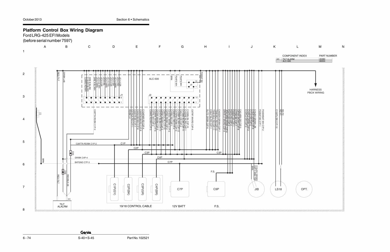
1
2
3
4
5
6
7
8
A B C D E F G H I J K L M N
October 2013 Section 6 • Schematics
6 - 74 S-40 • S-45 Part No. 102521
Platform Control Box Wiring DiagramFord LRG-425 EFI Models(before serial number 7597)
TILT ALARM 45383
COMPONENT INDEX PART NUMBER
H1
D4
0
RE
D/B
LK
-28
H1
ALALRMTILT
RE
D-T
ILT
D3
9
BR
N
BATGND C7P-3
GR/BK C4P-4
C3P
19/18 CONTROL CABLE
C1
P(G
Y)
C2
P(B
K)
C3
P(G
R)
C4
P(B
R)
12V BATT
C7P
C4P
C7P
C28TTA RD/BK C1P-2
DR
EA
BL
/WH
DR
EB
BL
/BK
C1
3L
ED
BL
/RD
C2
9M
SR
D/W
H
C2
8T
TA
RD
/BK
C1
P-2
RE
D-T
ILT
GR
/BK
L4
8
JC
3-2
BR
NJC
3-4
,6W
H
JC
2-2
BR
N
JC
1-2
BR
N
C1
34
PW
RR
DC
2P
-4
C3
3S
TR
BK
C1
P-7
C3
5R
PM
BK
/RD
C1
P-9
C3
4S
AB
K/W
HC
1P
-8
C2
7A
UX
RD
C1
P-1
C1P
C2P
J1
1
9
RD
/BK
L4
C2
9M
SR
D/W
HC
1P
-3
C5
TR
RW
H/B
KC
3P
-5C
32
BR
KW
H/R
DC
1P
-6C
4T
RL
WH
C3
P-4
C3
6S
TC
CB
LC
1P
-10
C3
PB
FR
D/W
HC
3P
-3C
37
ST
CB
L/B
KC
1P
-11
C2
PB
DR
D/B
KC
3P
-2C
31
ED
C-
WH
/BK
C1
P-5
C1
PB
UR
DC
3P
-1C
30
ED
C+
WH
C1
P-4
C4
1R
PM
OR
/BK
C2
P-3
C1
2S
BF
BL
/WH
C3
P-1
2C
40
LS
1O
RC
2P
-2C
11
SB
DB
L/B
KC
3P
-11
C1
3D
RE
BL
/RD
C4
P-1
C1
0S
BU
BL
C3
P-1
0
C6
TR
FW
H/R
DC
3P
-6
J2
1
11
1
JC
1-5
YE
L
JC
3-3
OR
JC
3-5
BL
JC
2-5
BK
JC
2-3
OR
JC
1-3
OR
JC
2-4
RD
ALC-500
BR
N
P2
4F
SW
H
P2
4F
SW
H J3
3
C3P
OPT.
F.S.
C9P
F.S.
LS18JIB
C4
P-7
AN
DT
S8
C1
9JS
VG
R/W
H
BR
NC
17
JU
GR
C4
P-5
DR
IVE
LT
BK
/RD
C3
P-9
JD
AL
AR
MG
R/B
KC
2P
-6
C4
3H
RN
GR
C2
P-5
C8
PB
RB
K/W
HC
3P
-8
C7
PB
EB
KC
3P
-7P
26
BA
TB
KC
9P
-1P
25
FS
RD
C9
P-3
P2
4F
SW
HC
9P
-2
C1
4P
LU
OR
C4
P-2
C1
5P
LD
OR
/BK
C4
P-3
DL
ITE
GR
/BK
C2
P-6
TS
48
-WL
1R
DC
2P
-12
TS
48
-WL
2R
DC
2P
-11
C4
5G
EN
GR
/WH
C2
P-7
C3
9L
PB
L/R
DC
2P
-1
C1
32
PL
IB
KC
1P
-12
C1
8JD
GR
/BK
C4
P-6
P2
2B
AT
BK
C7
P-1
P2
3S
WB
AT
WH
C7
P-2
C1
9JS
VG
R/W
HJIB
RD
P2
RD
H1
P2
6B
AT
BK
PBOX WIRING
HARNESS
ALC-500 89353

1
2
3
4
5
6
7
8
N M L K J I H G F E D C B A
Part No. 102521 S-40 • S-45 6 - 75
October 2013 Section 6 • Schematics
Platform Control Box Switch Panel Wiring DiagramFord LRG-425 EFI Models
(before serial number 7597)
EMERGENCY STOP
P2FUEL SELECT
DRV.ENATS15
L1
AUXILIARY
TS13PRIMARYBOOM
EXTEND/RETRACT
TS8
JIB
PLATFORM
TS7PLATFORM
LEVEL
TS9P3
HORN
ROTATE
TS1
TS47
JC3L1
JC2
TS1
TS13
TS4
TS15
TS8
TS3
L3
TS9
TS7
TS2
P2
P3
BOOM PROPORTIONAL JOYSTICK:
DRIVE PROPORTIONAL JOYSTICKDRIVE ENABLE LED
AUXILIARY SWITCH
GENERATOR SWITCH ( OPTION )
START ENGINE SWITCH
PLATFORM ROTATE SWITCH
PLATFORM LEVEL SWITCH
CHECK ENGINE LIGHT
JIB UP/DOWN SWITCH
PRIMARY BOOM EXTEND/RETRACT SWITCH
HI/L0 RPM SWITCH
DRIVE ENABLE SWITCH
FUEL SELECT SWITCH (FORD EFI ONLY)
EMERGENCY STOP BUTTON
COMPONENT INDEX
HORN SWITCH
PRIMARY UP/DN , TURNTABLE ROTATE
PART NUMBER
66812, 7380566813, 668164273013037
56457
16397130371303713037
1303727378
56298
62390
75565
GR
-43
OR
-14
OR
/BK
-15
C1
8JD
GR
/BK
C4
P-6
C1
9JS
VG
R/W
HJIB
C1
7JU
GR
C4
P-5
C2
7A
UX
RD
C1
P-1
BL
/RD
-39
WH
-23
P2
6B
AT
BK
C9
P-1
P2
2B
AT
BK
C7
P-1
BK
-22
RD
WH
GR
RD
TS3
BK
/WH
-8
BL
/RD
-DE
3J1
-16
BL
/WH
-DE
1J1
-6
BK
-7
WH
WH
JD
AL
AR
MG
R/B
K-4
4C
2P
-6
HARNESS
PBOX WIRING
DASHED LINES INDICATE
OPTION WIRES
NOTE:
RD
-TIL
T
BL
/BK
-DE
2J1
-7
4
2
1
3
5
6
7
OR
J1
-13
BR
NJ1
-14
BL
J1
-4
WH
J1
-5
OR
J1
-11
BR
NJ1
-12
BK
J1
-2
RD
J1
-1
JC3JC2
CR13
WH
-JIB
C1
9JS
VG
R/W
H
WH
-24
BR
N
WH
-JIB
4
2
1
3
5
6
7
REMOVE FOR GENERATOR OPTION
WH
-24
BK
-22
WH
-24
(SPLICE TO R40LS1)
(SPLICE TO C32BRK)
OR R40LS1
WH/RD C32BRK
WH TS7
CR30
CR27
WH TS1
DETAIL A: LIFT/DRIVE OPTION
REPLACE WIRE WITH THIS WIRING DIAGRAM
(GND STUD)
BRN BATGND
CE SEE DETAIL A
WORK /TS48 / TS49
DRIVE LITE
TS48-9 WORK/DRIVE LIGHT ( OPTION ) 27378
RD
WL
1
DL
ITE
/R
DW
L2
56457
WH
J1
-5
56298
RD
+
BK
/RD
-35
WH
-24
RPM
HIGH/LOW
TS4
START
TS2
BK
-33
RD
-25
DR
IVE
LT
BK
/RD
-C3
P-9
RD
/BK
H1
L4
+
RD
-TIL
T
WH
-TS
47
GENERATOR
(OPTION)
TS47
WH
-24
GR
/WH
-45
WH
-TS
4
RDPUMP
4 3NO
NC
NC
NC
11
1
22
2

October 2013 Section 6 • Schematics
6 - 76
Platform Control Box Switch Panel Wiring DiagramFord LRG-425 EFI Models(before serial number 7597)
6 - 75

October 2013Section 6 • Schematics
6 - 77
Electrical SchematicFord LRG-425 EFI Models
(from serial number 7597 to 11066)
6 - 78

1
2
3
4
5
6
7
8
A B C D E F G H I J K L M N
October 2013 Section 6 • Schematics
6 - 78 S-40 • S-45 Part No. 102521
Electrical SchematicFord LRG-425 EFI Models(from serial number 7597 to 11066)
STA
RT
ER
MO
TO
R
H2REGULATOR
- IND.
AU
XIL
IAR
YP
UM
P
AU
XIL
IAR
YP
OW
ER
RE
LA
YS
ER
VIC
EH
OR
N
SE
RV
ICE
HO
RN
RE
LA
Y
LE
VE
LS
EN
SO
R
TIL
TA
LA
RM
PUMP
BR
NB
K
12 V DC
+
+BAT.
STA.
BAT.-
ALTERNATOR
EXCT.
RD
-13
4
RD
-27
RD
/BK
-28
BK
-43
CR5
NO CR5
PR1
RD
WH
NO
PR1
HO
UR
ME
TE
R
_
STA
RT
RE
LA
Y
OTS
FL
AS
HIN
GB
EA
CO
NS
OP
TI O
N
OP
TIO
N
GE
NE
RA
TO
R
BK
-33
+
OPS
TB25 TB26
WH
-21
CR1
NO
TB21
CR1
GR
/WH
-45
FB
TB41
C4
1R
PM
OR
/BK
15AMP.TB20
CB2
RD
RD
15AMP.
CB1
RD
P2
3B
AT
WH
C2
8T
TA
RD
/BK
C2
7A
UX
RD
C4
3H
RN
GR
TB23
TB28
RD
TB27
C2
-5
TS51
C1
-2
C7
-2
C1
-1
TS1
C9-1 BKRD-(FS)
WH-(FS)BK-(FS)
FS1
C9-2
C9-3
C3
3S
TR
BK
TB33
BK
TS52
C1
-7
C4
5G
EN
GR
/WH
TB45
C2
-7
TS2
P24FS WH
P25FS RD
P26ESTP BK
BRN
C3
5E
SP
DB
K/R
D
HIG
HR
PM
LO
WR
PM
TB35
TS55
RD
RD
WH
BK
OR/BKC
1-9
GE
NE
RA
TO
R
G2 G3
G1
VO
LT
ME
TE
R
OIL
PR
ES
SU
RE
GA
UG
E
TE
MP
GA
UG
E
C5
-16
C5
-14
C6
-27
C6
-28
C6
-23
TB43
C6
-16
C5
-2
C5
-3
FAN
(OP
TIO
N)
CO
OL
ING
FA
N
TE
MP.S
WIT
CH
HY
DR
AU
LIC
OIL
NOOTS
CR17NO
CR17
CB3
20AMP.
C6
-33
C6
-34
C6
-25
TB134P1
RD
TB22
PLAT
GRD
KS1
RD
C1
34
PW
RR
DC
2-4
P2
2B
AT
BK
C7
-1
H1
RD
P2
C28TTA RD/BK
RD/BK
C1
33
PL
AO
R/R
D
C2-3
L48
D40
FU
NC
TIO
NE
NA
.
THIS WIRE FOR UNITS WITHOUT GENERATOR OPTION.
IN THE STOWED POSITION AND KEYSWITCH "OFF".
ALL SWITCHES AND CONTACTS ARE SHOWN WITH THE BOOM
NOTE:
WH
/BK
WH
/RD
C6
-39
L2
D6
C6
-26
TS17
TS4
HIG
HR
PM
(FS
)
F18
BK
BK
WH
WH
TS49
RD
RD
OP
TIO
NW
OR
KL
IGH
TS
OP
TIO
ND
RI V
EL
I GH
T
CR23CR23
NO
PBOX GND
DL
ITE
BK
/RD
C3
-9
FUSE 10A
L29 L29
L30L30
2
M1
S7
M2
PR2PR2
G6Y29
C4
B-1
1
C4
B-1
2
DG
RN
(FE
H2
42
)
LP
GL
OC
KO
UT
SO
LE
NO
ID
FORDENGINE
HARNESS
RD
(FE
H3
61
A)
BL
/WH
PIN
5
FU
EL
PU
MP
FUELPUMP
C2
-1
TB39
TS53
TS3
BK
PIN
13
BK
PIN
15
C3
9L
PB
L/R
DP
IN7
RD
PIN
9
WH
PIN
1
C3
8E
SL
BL
/WH
PIN
6
TS22
GR
PIN
18
C1
27
TS
T
BR
PIN
34
BK
/RD
PIN
23
C3
5R
PM
42
PIN
PL
UG
FO
RD
CR39
NC
CR39
TB24
WH
PIN
21
VS
W
VB
AT
T
C3
3S
TR
C2
1IG
N
R3
3S
TR
CR2NO
CR2
C5
-11
C5
-10
C5
-12
C5
-5
C5
-17
C5
-9
C5
-13
BL/WH
C4
1R
PM
OR
/BK
PIN
24
2P
INF
OR
DC
ON
NE
CT
OR
R2
1IG
NW
HP
IN2
4C
5-8
2
1.
3 REFER TO E0375 FOR FORD HARNSS
3
51
0O
HM
STARTERAUXHM
HORNP3
PU
MP
AU
XIL
IAR
Y
PU
MP
AU
XIL
IAR
Y
LP
GA
S FU
EL
STA
RT
EN
GIN
EE
NG
INE
STA
RT
TB 134 IS WAGO TERMINAL BLOCK 42

1
2
3
4
5
6
7
8
N M L K J I H G F E D C B A
Part No. 102521 S-40 • S-45 6 - 79
October 2013 Section 6 • Schematics
Electrical SchematicFord LRG-425 EFI Models
(from serial number 7597 to 11066)
POSITION EXCEPT AS NOTED.
1) ALL LIMIT SWITCHES SHOWN WITH THE BOOM IN STOWED
NOTE:
MO
TO
RS
TR
OK
E
Y27
C2
9M
SR
D/W
HC
5-1
9C
1P
-3
BL/WH
Y51Y2Y3Y4Y23Y29Y13Y22Y21Y12H4Y25Y26Y20Y19Y16Y17
5
R1 R2
7.5
RD/BK
C1
5P
LD
OR
/BK
C1
4P
LU
OR
C1
3D
RE
BL
/RD
C6
-30
C6
-19
RD
/BK
CD
BA
C1
8JD
GR
/BK
C1
7JU
GR
C4
0L
S1
OR
SJ1-WH
C8
PB
RB
K/W
H
C7
PB
EB
K
C3
PB
FR
D/W
H
C2
PB
DR
D/B
K
C1
PB
UR
D
C4
TR
LW
H
C5
TR
RW
H/B
K
C6
TR
FW
H/R
D
C3
6S
TC
BL
C3
7S
TC
CB
L/B
K
C3
2B
RK
WH
/RD
C3
0E
DC
+W
H
C3
1E
DC
-W
H/B
K
C6
-14
C6
-15
C6
-40
C6
-13
C6
-32
5
L1TS15
JC3DRIVE & STEERING
6 7
GN
D
PW
R
5421 3
YO
UT
RK
OU
T
158
167
J1
64 5
14
13
J1
DR
EL
ED
BL
/RDW
H
BL
OR
BR
N
DR
EB
BL
/BK
DR
EA
BL
/WH
JC2
PW
R
653 421
GN
D
XO
UT
YO
UT
PRI UP/DN & TT ROTATE
7
9
211 1
12
J1
6
J2
OR
BR
N
BK
RD
C2
P-3
BR
N-2
C1
P-5
C1
P-4
C1
P-1
0
C1
P-1
1
C1
P-6
C3
P-5
C3
P-4
C3
P-6
C3
P-1
TS62 C4
TR
LW
H
TS61
C1
PB
UR
D
TB30TB31
TB36 TB37 TB32TB4
TB5TB2
TB1
C6
-5
C6
-1TB3 TB6
C5
TR
RW
H/B
K
C3
1E
DC
-W
H/B
K
C3
7S
TC
CB
L/B
K
C3
6S
TC
BL
C6
TR
FW
H/R
D
C3
2B
RK
WH
/RD
C3
0E
DC
+W
H
10
11
18
17
20
19
15
16
C4
1R
PM
OR
/BK
78
243 1
J3
3P
26
ES
TP
BK
P2
4F
SW
H
P2
4F
SW
H
BR
N
NCCR27
CR30NO
4DRIVELIFT/
OPTION
CE
TS13
JOYSTICK CONTROL CARD
OR/BK
BK
WH
CR13NC
WH
GR
/BK
-44
TS7TS8
CR13
WH
JIB
VA
LV
E
BRN
TS9
C3
P-3
C3
P-2
C4
P-1
TS63
C1
3D
RE
BL
/RD
C2
P-2
C3
P-8
C3
P-7
C4
P-3
C4
P-2
C4
0L
S1
OR
C8
PB
RB
K/W
H
C7
PB
EB
K
TB40 TB13TB7
TB8
C6
-7
TB14
C1
5P
LD
OR
/BK
C1
4P
LU
OR
C2
PB
DR
D/B
K
C3
PB
FR
D/W
H
C4
P-6
C2
P-6
C4
P-5
TB44
TS58
TS57
C1
8JD
GR
/BK
C1
7JU
GR
JD
AL
AR
MG
R/B
K
C4
P-7
RD
RD
C1
9JS
VG
R/W
H
TB15
C6
-17
TB18
TB17
TB19
TS59
C19JSV GR/WH
12
13
14
GR
OU
ND
H4
C5
-23
C5
-20
C6
-37
C6
-36
C5
-21
ST
EE
RR
IGH
T
ST
EE
RL
EF
T
FL
OW
CO
NT
RO
L
PR
IMA
RY
BO
OM
UP
PR
IMA
RY
BO
OM
FL
OW
CO
NT
RO
L
TU
RN
TA
BL
ER
OTA
TE
TU
RN
TA
BL
ER
OTA
TE
RIG
HT
TU
RN
TA
BL
ER
OTA
TE
LE
FT
PR
IMA
RY
BO
OM
DO
WN
DR
IVE
ED
CF
OR
WA
RD
DR
IVE
ED
CR
EV
ER
SE
TR
AV
EL
AL
AR
MO
PT
ION
BR
AK
ER
EL
EA
SE
VA
LV
E
BK
WH
NOHC
DR
IVE
EN
AB
LE
LIM
ITS
WIT
CH
BO
OM
EX
TE
ND
BK
WH
BK
WH
NCHONOHC
DR
IVE
LIM
ITS
WIT
CH
PL
AT
LE
VE
LD
OW
N
PL
AT
LE
VE
LU
P
BRN
JIB
VA
LV
ES
PL
AT
FO
RM
RO
TA
TE
LE
FT
/JIB
UP
PL
AT
FO
RM
RO
TA
TE
RIG
HT
/JIB
DO
WN
DE
SC
EN
TA
LA
RM
OP
TIO
N
LS
2-P
RIM
AR
YB
OO
MU
P
LS
1-P
RIM
AR
YB
OO
ME
XT
EN
D
BO
OM
RE
TR
AC
T
DR
IVE
LIM
ITS
WIT
CH
C6
-18
C6
-8
C6
-3
C6
-2
C6
-6
C6
-4
TB29
C2
9M
SR
D/W
H
TS14
RIG
HT
LE
FT
PL
AT
RO
TA
TE
DO
WN
UP
JIB
BO
OM
UP
DO
WN
PL
AT
FO
RM
LE
VE
L
EX
TE
ND
RE
TR
AC
TP
LA
TF
OR
ML
EV
EL
PL
AT
RO
TA
TE
RIG
HT
LE
FT
DO
WN
UP
JIB
BO
OM
UP
DO
WN P
LA
TF
OR
ML
EV
EL
EX
TE
ND
RE
TR
AC
TB
OO
M
UP
DO
WN
PR
IMA
RY
BO
OM
LE
FT
RIG
HT T
RO
TA
TE
1
2
34
5
6
7
6
5
4
3
2
1
Deutsch
AMP
Pin1
Pin 1 GND Pin 2
Pin 2 PWR Pin 3
Pin 3 XOUT Pin 4
Pin 4 YOUT Pin 5
Pin 5 RKOUT Pin 6
Pin 6 Pin 7
Joystick Adaptor Harness

October 2013 Section 6 • Schematics
6 - 80
Electrical SchematicFord LRG-425 EFI Models(from serial number 7597 to 11066)
6 - 79

1
2
3
4
5
6
7
8
N M L K J I H G F E D C B A
Part No. 102521 S-40 • S-45 6 - 81
October 2013 Section 6 • Schematics
Ground Control Box Wiring DiagramFord LRG-425 EFI Models
(from serial number 7597 to 11066)E
NG
INE
C5
BRN GND
WH-23C
BK-22C
BR-GND STUD
12
VT
OP
LA
T
C1
B
FU
NC
TIO
NS
C6
C3
B
19
/18
CA
BL
ES
C2
BC
4B
3
2C7
B 1
CR23
RD C4B-11
RD C4B-12
RD-CB3 SP
ALL BR WIRES
BRGROUND STUD
GR
OU
ND
ST
UD
DRIVE LIGHT OPTION RELAY
12
V
CHECK ENGINE
CHECK ENGINE SWITCH
JIB BOOM UP/DOWN SWITCH
ENGINE START SWITCH
EMERGENCY STOP BUTTON
AUXILIARY SWITCH
DESCRIPTION
FUNCTION ENABLE
PLATFORM LEVEL SWITCH
VOLT METER GAGE
OIL PRESSURE GAGE
WATER TEMP. GAGE
TURNTABLE ROTATE SWITCH
PLATFORM ROTATE SWITCH
PRIMARY BOOM UP/DOWN SWITCH
CIRCUIT BREAKER, CONTROLS, 15A
CIRCUIT BREAKER, ENGINE, 15A
BOOM EXTEND/RETRACT SWITCH
RESISTOR, 7.5 OHM,TURNTABLE FUNCT
G3
L2
G1
G2
LABEL
TS22
HM
R2
CB2
CB1
TS62
TS58
TS63
TS61
HOUR METER
TS52
TS59
TS57
TS55
KS1
TS51
P1
KEY SWITCH
32WH/RD-C1B-6
11BL/BK-C3B-11BL-C3B-10
BK/WH-C3B-8BK/RD-C3B-9
RD/WH-C3B-3WH-C3B-4WH/BK-C3B-5WH/RD-C3B-6BK-C3B-7
RD-C3B-1RD/BK-C3B-2
RD-C6-1
D
BK/WH-C6-8
WH/BK-C6-5
RD/WH-C6-3WH- C6-4
WH/RD-C6-6BK- C6-7
RD/BK-C6-2
C B
6
2
3
1
54
8
7
109
44B-RD/BK-C6-19
WH/BK-C1B-5
WH-C1B-4RD/WH-C1B-3
RD-C1B-1
WH-C7B-2
RD/BK-C1B-2
GR/WH-C4B-7GR/BK-C4B-6
BK-C7B-1WH-C5-3+C5-8
GR-C4B-5OR/RD-C4B-4
OR-C4B-2OR/BK-C4B-3
BL/RD-C4B-1BL/WH-C3B-12
GR/BK-C6-18
WH-CR2#87
GR- C6-17
BL/RD-C6-13
RD- C6-23
WH-C6-34
RD- C6-27
BK-CR5#30WH-S.P.
16
13
12
15
14
1918
17
2120
CR39 #30
RED-CR1#30
RD-CR39#85
242322
2526
2928
27
3031
GR/BK-C2B-6GR/WH-C2B-7
OR/BK-C2B-3
BL/RD-C2B-1OR-C2B-2
OR/RD-C2B-4
BK/RD-C1B-9BK/WH-C1B-8
BL/BK-C1B-11
BL-C1B-10
BL/WH-C1B-12
BK-C1B-7
BK/RD-C5-9
BL/RD-C5-10OR- C6-40OR/BK-C5-2
GR/WH-C6-39
42
BK-CR1#85
37
3433
3536
39
38
4041
D5
4443
45
RD-S.P.
TURN. ROT. R
PRI. BOOM DOWN
PRI. BOOM F.C.
TURN. ROT. LTURN. ROT. F.C.BOOM EXTENDBOOM RETRACT
PRI. BOOM UP
WH/RD-S.P.
RD/WH-S.P.
WH/BK-S.P.
RD/BK-S.P.
WH-S.P.
BK/WH-S.P.
BK-S.P.
JIB VALVE
PLAT. LEVEL. UPPLAT. LEVEL DN.
PLAT. ROT. L.PLAT. ROT. R.
DRV. ENA. LT.
IGNITION PWR.
OR/BK-S.P.OR-S.P.
GR/WH-SPGR/BK-S.P.GR-S.P.
TILT ALARM
E.D.C.+
E.D.C.-
AUX. PWR.
KEYSWITCH PWR/FBPWR. TO PLAT.
ENGINE POWER
WH/BK-S.P.WH/RD-S.P.
RD-S.P.
WH-S.P.BK-S.P.
RD-S.P.
C134PWR
LIMIT SWITCH SIG.
GLOW PLUG
STEER LEFT
RPM
STEER RIGHT
C132PLI
START
PULSE PICKUP
BK/WH-S.P.BK/RD-S.P.
BK-S.P.
BL/RD-S.P. L.P.
GEN. OPTIONJDALARM JIB
HORN
BRAKE/TRAVEL ALARM
OIL PRESSURE SENDERWATER TEMP. SENDER
TS22
BK-C5-5 WH-21B
RD-24B
CR1 CR2
BL- C6-36BL/BK-C6-37
RD/BK-C6-28
OR- C6-14
OR/BK-C6-15
SPARE46
MOTOR SPEED
TS53LP/GAS SWITCH
WH/BK-C5-20WH- C5-21
WH/RD-C5-23 WH/RD-C6-32
GR-C2B-5 GR-CR5#85
PART #
P1
KS1
16397
13037
56457
13037
13037
13480
13037
CB1
CB2
42730
16397
16397
13037
56298
G3
G2
G1
R2
HM
CB3CB3CIRCUIT BREAKER, OPTIONS, 20A
BL/WH-C6-30
TS63
TS58
GR/BK-18A
WIRING
TO BASEHARNESS:
GR/WH-19A
GR-17A
OR-14A
OR/BK-15A
RD- P1 E-STOP
RD- 20B
TS55
RD- 24A
RD- 20A
BK/RD-35A
D13
TS52
WH/BK-5A
WH/RD-6A
RD-CR17#30
RD- 20C
WH-4A
D14
GR/BK-44A
BK-33A
BK/WH-8A
BK-7A
CB2CB1
R2
CB3
BR (GROUND)
HM
RD/WH-3A
RD/BK-2A
RD-1A
BR (GROUND)
WH-21A
L2
RD-27ARD-42A
WH-23A
RD-CB2
NC
NC
P1
BK-22A
WH/BK-25A
WH/RD-26A
KEY SWITCHB
B1
1
24
3
RD
KS1
WH-21A
G1 G2
TS59
TS57
TS62
TS61
TS51
G3
BL/RD-39A
TS53
A
GR/BK-2B GR/BK-SP
R1R1RESISTOR, 5 OHM, BOOM FUNCTION
R1
C133PLT
BK-33B
WH-C5-17
GR-C5-12
BL/WH-C23-3
RD-H6+
GR/BK-C23-8 GR/BK-H6-
DRIVE LIGHT OPTIONBK/RD-CR23#86
BK/RD-9B
WH-C5-11
RD-27B
BK-C6-16
GR-43BBK-22B
CR5
OR-C6-33
RD-CB3 SP
CR39BK-C6-25
CR17
WH/RD-C5-14
WH/BK-C5-16
BL/WH-C5-13
RD-KS1-2 S.P.
RD- 12 VOLT RD-S.P.(CB3) RD-S.P.(CB2) RD-S.P.(CB1) 12V BATTERY SUPPLY
RD/WH-C5-24
WH-23B
October 2013 Section 6 • Schematics
6 - 82
Ground Control Box Wiring DiagramFord LRG-425 EFI Models(from serial number 7597 to 11066)
6 - 81

October 2013Section 6 • Schematics
6 - 83
Platform Control Box Wiring DiagramFord LRG-425 EFI Models
(from serial number 7597 to 11066)
6 - 84

1
2
3
4
5
6
7
8
A B C D E F G H I J K L M N
October 2013 Section 6 • Schematics
6 - 84 S-40 • S-45 Part No. 102521
Platform Control Box Wiring DiagramFord LRG-425 EFI Models(from serial number 7597 to 11066)
TILT ALARM 45383
COMPONENT INDEX PART NUMBER
H1
D4
0
RE
D/B
LK
-28
H1
ALALRMTILT
RE
D-T
ILT
D3
9
BR
N
BATGND C7P-3
GR/BK C4P-4
C3P
19/18 CONTROL CABLE
C1
P(G
Y)
C2
P(B
K)
C3
P(G
R)
C4
P(B
R)
12V BATT
C7P
C4P
C7P
C28TTA RD/BK C1P-2
DR
EA
BL
/WH
DR
EB
BL
/BK
C1
3L
ED
BL
/RD
C2
9M
SR
D/W
H
C2
8T
TA
RD
/BK
C1
P-2
RE
D-T
ILT
GR
/BK
L4
8
JC
3-2
BR
NJC
3-4
,6W
H
JC
2-2
BR
N
JC
1-2
BR
N
C1
34
PW
RR
DC
2P
-4
C3
3S
TR
BK
C1
P-7
C3
5R
PM
BK
/RD
C1
P-9
C3
4S
AB
K/W
HC
1P
-8
C2
7A
UX
RD
C1
P-1
C1P
C2P
J1
1
9
RD
/BK
L4
C2
9M
SR
D/W
HC
1P
-3
C5
TR
RW
H/B
KC
3P
-5C
32
BR
KW
H/R
DC
1P
-6C
4T
RL
WH
C3
P-4
C3
6S
TC
BL
C1
P-1
0C
3P
BF
RD
/WH
C3
P-3
C3
7S
TC
CB
L/B
KC
1P
-11
C2
PB
DR
D/B
KC
3P
-2C
31
ED
C-
WH
/BK
C1
P-5
C1
PB
UR
DC
3P
-1C
30
ED
C+
WH
C1
P-4
C4
1R
PM
OR
/BK
C2
P-3
C1
2S
BF
BL
/WH
C3
P-1
2C
40
LS
1O
RC
2P
-2C
11
SB
DB
L/B
KC
3P
-11
C1
3D
RE
BL
/RD
C4
P-1
C1
0S
BU
BL
C3
P-1
0
C6
TR
FW
H/R
DC
3P
-6
J2
1
11
1
JC
1-5
YE
L
JC
3-3
OR
JC
3-5
BL
JC
2-5
BK
JC
2-3
OR
JC
1-3
OR
JC
2-4
RD
ALC-500
BR
N
P2
4F
SW
H
P2
4F
SW
H J3
3
C3P
OPT.
F.S.
C9P
F.S.
LS18JIB
C4
P-7
AN
DT
S8
C1
9JS
VG
R/W
H
BR
NC
17
JU
GR
C4
P-5
DR
IVE
LT
BK
/RD
C3
P-9
JD
AL
AR
MG
R/B
KC
2P
-6
C4
3H
RN
GR
C2
P-5
C8
PB
RB
K/W
HC
3P
-8
C7
PB
EB
KC
3P
-7P
26
BA
TB
KC
9P
-1P
25
FS
RD
C9
P-3
P2
4F
SW
HC
9P
-2
C1
4P
LU
OR
C4
P-2
C1
5P
LD
OR
/BK
C4
P-3
DL
ITE
BK
/RD
C3
P-9
TS
48
-WL
1R
DC
2P
-12
TS
48
-WL
2R
DC
2P
-11
C4
5G
EN
GR
/WH
C2
P-7
C3
9L
PB
L/R
DC
2P
-1
C1
32
PL
IB
KC
1P
-12
C1
8JD
GR
/BK
C4
P-6
P2
2B
AT
BK
C7
P-1
P2
3S
WB
AT
WH
C7
P-2
C1
9JS
VG
R/W
HJIB
RD
P2
RD
H1
P2
6B
AT
BK
PBOX WIRING
HARNESS
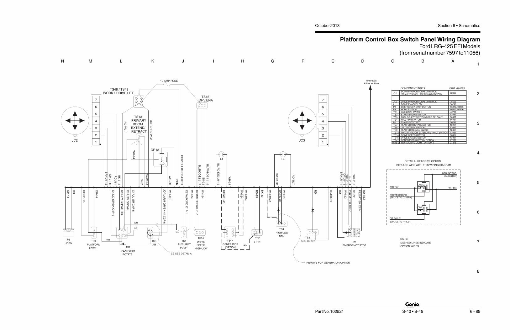
1
2
3
4
5
6
7
8
N M L K J I H G F E D C B A
Part No. 102521 S-40 • S-45 6 - 85
October 2013 Section 6 • Schematics
Platform Control Box Switch Panel Wiring DiagramFord LRG-425 EFI Models
(from serial number 7597 to11066)
EMERGENCY STOP
P2FUEL SELECT
DRV.ENATS15
L1
AUXILIARY
TS13PRIMARYBOOM
EXTEND/RETRACT
TS8
JIB
PLATFORM
TS7PLATFORM
LEVEL
TS9P3
HORN
ROTATE
TS1
TS47
JC3
L1
JC2
TS1
TS13
TS4
TS15
TS8
TS3
L4
TS9
TS7
TS2
P2P3
BOOM PROPORTIONAL JOYSTICK:
DRIVE PROPORTIONAL JOYSTICKDRIVE ENABLE LED
AUXILIARY SWITCH
GENERATOR SWITCH ( OPTION )
START ENGINE SWITCH
PLATFORM ROTATE SWITCH
PLATFORM LEVEL SWITCH
CHASSIS TILT LED
JIB UP/DOWN SWITCH
PRIMARY BOOM EXTEND/RETRACT SWITCH
HI/L0 RPM SWITCH
DRIVE ENABLE SWITCH
FUEL SELECT SWITCH (FORD EFI ONLY)
EMERGENCY STOP BUTTON
COMPONENT INDEX
HORN SWITCH
PRIMARY UP/DN , TURNTABLE ROTATE
PART NUMBER
66812, 9450666813, 668164273013037
56457
16397130371303713037
1303727378
56298
62390
75565
GR
-43
OR
-14
OR
/BK
-15
C1
8JD
GR
/BK
C4
P-6
C1
9JS
VG
R/W
HJIB
C1
7JU
GR
C4
P-5
C2
7A
UX
RD
C1
P-1
BL
/RD
-39
WH
-23
P2
6B
AT
BK
C9
P-1
P2
2B
AT
BK
C7
P-1
BK
-22
RD
WH
GR
RD
TS3
BK
/WH
-8
BL
/RD
-DE
3J1
-16
BL
/WH
-DE
1J1
-6
BK
-7
WH
WH
JD
AL
AR
MG
R/B
K-4
4C
2P
-6
HARNESS
PBOX WIRING
DASHED LINES INDICATE
OPTION WIRES
NOTE:
RD
-TIL
T
BL
/BK
-DE
2J1
-7
4
2
1
3
5
6
7
OR
J1
-13
BR
NJ1
-14
BL
J1
-4
WH
J1
-5
OR
J1
-11
BR
NJ1
-12
BK
J1
-2
RD
J1
-1
JC3JC2
CR13
WH
-JIB
C1
9JS
VG
R/W
H
WH
-24
BR
N
WH
-JIB
4
2
1
3
5
6
7
REMOVE FOR GENERATOR OPTION
WH
-24
BK
-22
WH
-24
(SPLICE TO R40LS1)
(SPLICE TO C32BRK)
OR R40LS1
WH/RD C32BRK
WH TS7
CR30
CR27
WH TS1
DETAIL A: LIFT/DRIVE OPTION
REPLACE WIRE WITH THIS WIRING DIAGRAM
(GND STUD)
BRN BATGND
CE SEE DETAIL A
WORK /TS48 / TS49
DRIVE LITE
TS48-9 WORK/DRIVE LIGHT ( OPTION ) 27378
RD
WL
1
DL
ITE
/R
DW
L2
56457
WH
J1
-5
56298
RD
+
BK
/RD
-35
WH
-24
RPM
HIGH/LOW
TS4
START
TS2
BK
-33
RD
-25
DR
IVE
LT
BK
/RD
-C3
P-9
RD
/BK
H1
L4
+
RD
-TIL
T
WH
-TS
47
10 AMP FUSE
DRIVE
TS14
C2
9M
SR
D/W
HJ1
-8
WH
-24
SPEED
HIGH/LOW
GENERATOR
(OPTION)
TS47
WH
-24
GR
/WH
-45
WH
-TS
4
RD
TS14 DRIVE SPEED SWITCH 56457
PUMP
4 3NO
NC
NC
NC
22
2
11
1

October 2013 Section 6 • Schematics
6 - 86
Platform Control Box Switch Panel Wiring DiagramFord LRG-425 EFI Models(from serial number 7597 to 11066)
6 - 85

October 2013Section 6 • Schematics
6 - 87
Electrical SchematicFord DSG-423 EFI Models
(from serial number 11067 to 12509)
6 - 88

1
2
3
4
5
6
7
8
A B C D E F G H I J K L M N
October 2013 Section 6 • Schematics
6 - 88 S-40 • S-45 Part No. 102521
B1
B3
1
4
2
C2
7A
UX
RD
P2
0B
AT
RD
BL/WH
C4
B-1
2
C4
B-1
1
Y29
G6
PR
2
PR
2
M2
S7
M1
L30 L30
L29L29
FUSE 10A
C3
-9D
LIT
EB
K/R
D
PBOX GND
NOCR23
CR23
DR
IVE
LIG
HT
OP
TIO
N
WO
RK
LIG
HT
S
OP
TIO
N
RD
RD
TS49
WH W
H
BK
BK
F18
HIG
HR
PM
(FS
)
TS4
TS17
C6
-26
C6
-39
WH
/BK
FU
NC
TIO
NE
NA
.
L48
C2
-3
C1
33
PL
AO
R/R
D
RD/BK
C28TTA RD/BK
P2
RD
P3H1
C7
-1
HORN
P2
2B
AT
BK
C2
-4C
13
4P
WR
RD
RD
KS1
GRD
PLAT
TB22RD
P1TB42
C6
-25
C6
-34
C6
-33
20AMP. CB3
CR17
NOCR17
OTS
NO
HY
DR
AU
LIC
OIL
TE
MP.S
WIT
CH
CO
OL
ING
FA
N(O
PT
ION
)
C5
-2
C6
-16
TB43
C6
-23
C6
-28
C6
-27
C5
-16
TE
MP
GA
UG
E
OIL
PR
ES
SU
RE
GA
UG
E
VO
LT
ME
TE
R
G1
G3
G2
GE
NE
RA
TO
R
C1
-9
OR/BK
BK
WH
RD
RD
TS55
TB35
LO
WR
PM
HIG
HR
PM
C3
5E
SP
DB
K/R
D
BRN
P26ESTP BK
P25FS RD
P24FS WH
TS2
C2
-7
TB45
C4
5G
EN
GR
/WH
C1
-7
TS52
TB33
C3
3S
TR
BK
C9-3
C9-2
FS1
BK(FS)WH(FS)
RD(FS)C9-1 BK
TS1
C1
-1
C7
-2
C1
-2
TS51
C2
-5
TB27
RD
TB28
TB23
C4
3H
RN
GR
C2
7A
UX
RD
C2
8T
TA
RD
/BK
P2
3B
AT
WH
CB1
15
AM
P.
RD
RD
CB2
TB20 15AMP.
C4
1R
PM
OR
/BK
TB41
FB
GR
/WH
TB21
R2
1IG
NW
H
TB26
TB25
OPS
+
GE
NE
RA
TO
R
OP
TIO
N
OP
TIO
N
FL
AS
HIN
GB
EA
CO
NS
_
HO
UR
ME
TE
R
PR1
NO
WH
RD
PR1
CR5NOCR5
R4
3H
RN
BK
RD
/BK
RD
+
DC12 V
BK PUMP
TIL
TA
LA
RM
LE
VE
LS
EN
SO
R
RE
LA
Y
SE
RV
ICE
HO
RN
SE
RV
ICE
HO
RN
RE
LA
Y
AU
XIL
IAR
YP
OW
ER
AU
XIL
IAR
YP
UM
P
-
H2
STA
RT
ER
MO
TO
R
1K
R3
WH
/RD
PIN
39
DIAGNOSTIC
BL
UE
/PIN
KH
AR
NE
SS
EN
GIN
EF
OR
D
C1
35
RE
T
C1
35
FP
BL
PIN
18
GA
SO
LIN
ES
EN
SO
R
GY
/RD
GY
/YL
RD
BK
/BL
D C B A
C5
-8W
HP
IN2
4R
21
IGN
42
PIN
FO
RD
CO
NN
EC
TO
RO
R/B
KP
IN2
C4
1R
PM
C5
-13
C5
-9
C5
-17
C5
-5
C5
-12
C5
-10
C5
-11
CR2
NOCR2
R3
3S
TR
C2
1IG
N
VS
W
WH
PIN
16
TB24
CR39
NCCR39
FO
RD
42
PIN
PL
UG
C3
5R
PM
BK
/RD
PIN
23
C1
27
TS
WG
RP
IN3
TS22
BL
/WH
PIN
6C
38
ES
L
WH
PIN
1
BL
/RD
PIN
7C
39
LP
BK
PIN
15
TS3
TS53
TB39
C2
-1
PUMPFUEL
FUEL PUMP
BL
/WH
PIN
5
RD
/GN
HARNESSENGINEFORD
LP
GL
OC
KO
UT
WH
/BK
L2
C2
6T
SR
C5
-14
CR1
NOCR1
STA
RT
ER
RE
LA
Y
BR
N
TB9
2
1.
2
NOTE:
ALL SWITCHES AND CONTACTS ARE SHOWN WITH THE BOOM
IN THE STOWED POSITION AND KEYSWITCH "OFF".
THIS WIRE FOR UNITS WITHOUT GENERATOR OPTION.
FAN
HM
AU
XIL
IAR
YP
UM
P
AU
XIL
IAR
YP
UM
P
LP
GA
SF
UE
L
LP
GA
SF
UE
L
STA
RT
EN
GIN
E
STA
RT
EN
GIN
E
WO
RK
LI G
HT
DR
IVE
LIG
HT
ESO433B
C1
07
AF
WH
C5
-3T
OA
LT
ER
NA
TO
RF
IEL
D5
00
AUX
R4
3
3 RESISTOR R4 REMOVED AT SERIAL NUMBER 11785 .
Electrical SchematicFord DSG-423 EFI Models(from serial number 11067 to 12509)
TB 134 IS WAGOTERMINAL BLOCK 42

1
2
3
4
5
6
7
8
N M L K J I H G F E D C B A
Part No. 102521 S-40 • S-45 6 - 89
October 2013 Section 6 • Schematics
Electrical SchematicFord DSG-423 EFI Models
(from serial number 11067 to 12509)
WH C2
9M
SR
D/W
H
LOHI
DR
IVE
SP
EE
D
TS14
CR30NO
NCCR27
5
R1 R2
C6
-30
C2
9M
SR
D/W
H
TB29
C6
-4
C6
-6
C6
-2
C6
-3
C6
-8
C6
-18
DR
IVE
LIM
ITS
WIT
CH
BO
OM
RE
TR
AC
T
LS
1-P
RIM
AR
YB
OO
ME
XT
EN
D
LS
2-P
RIM
AR
YB
OO
MU
P
DE
SC
EN
TA
LA
RM
OP
TIO
N
PL
AT
FO
RM
RO
TA
TE
RIG
HT
/JIB
DO
WN
PL
AT
FO
RM
RO
TA
TE
LE
FT
/JIB
UP
BRN
PL
AT
LE
VE
LU
P
PL
AT
LE
VE
LD
OW
N
DR
IVE
LIM
ITS
WIT
CH
NOHC NCHO
WH
BK
WH
BK
BO
OM
EX
TE
ND
LIM
ITS
WIT
CH
DR
IVE
EN
AB
LE
NOHC
WH
BK
BR
AK
ER
EL
EA
SE
VA
LV
E
TR
AV
EL
AL
AR
MO
PT
ION
DR
IVE
ED
CR
EV
ER
SE
DR
I VE
ED
CF
OR
WA
RD
PR
IMA
RY
BO
OM
DO
WN
TU
RN
TA
BL
ER
OTA
TE
LE
FT
TU
RN
TA
BL
ER
OTA
TE
RI G
HT
TU
RN
TA
BL
ER
OTA
TE
FL
OW
CO
NT
RO
LP
RIM
AR
YB
OO
M
PR
I MA
RY
BO
OM
UP
FL
OW
CO
NT
RO
L
ST
EE
RL
EF
T
ST
EE
RR
IGH
T
C5
-21
C6
-36
C6
-37
C5
-20
C5
-23
H4
14
13
12
TS59
TB19
TB17
TB18
C6
-17
TB15
C1
9JS
VG
R/W
H
RD
RD
C4
P-7
TS57
C4
P-5
C4
P-6
C3
PB
FR
D/W
H
C2
PB
DR
D/B
K
C1
4P
LU
OR
C1
5P
LD
OR
/BK
TB14
C6
-7
TB8
TB7 TB13TB40
C7
PB
EB
K
C8
PB
RB
K/W
H
C4
0L
S1
OR
C4
P-2
C4
P-3
C3
P-7
C3
P-8
C2
P-2
C1
3D
RE
BL
/RD
TS63
C4
P-1
C3
P-2
C3
P-3
TS9
WH
TS7
WH
BK
OR/BK
JOYSTICK CONTROL CARD
TS13
CE
OPTION
LIFT/DRIVE
4
P2
4F
SW
H
P2
4F
SW
H
P2
6E
ST
PB
K3
J3
13 4 2
8 7
C4
1R
PM
OR
/ BK1
6
15
19
20
17
1811
10
C3
0E
DC
+W
H
C3
2B
RK
WH
/RD
C6
TR
FW
H/R
D
C3
6S
TC
BL
C3
7S
TC
CB
L/B
K
C3
1E
DC
-W
H/B
K
C5
TR
RW
H/B
K
TB6TB3
C6
-1
C6
-5
TB1
TB2 TB5
TB4 TB32TB37
TB36
TB31 TB30
C1
PB
UR
D
TS61 C4
TR
LW
H
TS62
C3
P-1
C3
P-6
C3
P-4
C3
P-5
C1
P-6
C1
P-1
1
C1
P-1
0
C1
P-4
C1
P-5
BR
N-2
C2
P-3
RD
BK
BR
N
OR
J2
6
J1
12 1
11 2
9
7
PRI UP/DN & TT ROTATE
YO
UT
XO
UT
GN
D
1 2 43 5 6
PW
R
JC2
DR
EA
BL
/WH
DR
EB
BL
/BK
BR
N
OR
BL
WH
DR
EL
ED
BL
/ RD
J1
13
14 54 6
J1
7
16 8
15
RK
OU
T
YO
UT
31 2 4 5
PW
R
GN
D
76
DRIVE & STEERING
JC3 TS15L1
5
C6
-32
C6
-13
C6
-40
C6
-15
C6
-14
C3
1E
DC
-W
H/B
K
C3
0E
DC
+W
H
C3
2B
RK
WH
/RD
C3
7S
TC
CB
L/B
K
C3
6S
TC
BL
C6
TR
FW
H/R
D
C5
TR
RW
H/ B
K
C4
TR
LW
H
C1
PB
UR
D
C2
PB
DR
D/B
K
C3
PB
FR
D/ W
H
C7
PB
EB
K
C8
PB
RB
K/W
H
SJ1-WH
C4
0L
S1
OR
AB
DC
C6
-19
RD
/BK
C1
3D
RE
BL
/RD
C1
4P
LU
OR
C1
5P
LD
OR
/BK
RD/BK
7.5
Y17 Y16 Y19 Y20 Y26 Y25 H4 Y12 Y21 Y22 Y13 Y29 Y23 Y4 Y3 Y2
Y51
BL/WH
C1
P-3
C5
-24
C2
9M
SR
D/W
H
Y27
MO
TO
RS
TR
OK
E
GR
OU
ND
BR
N
NOTE:
1) ALL LIMIT SWITCHES SHOWN WITH THE BOOM IN STOWED
POSITION EXCEPT AS NOTED.
JIB
VA
LV
ES
C19JSV GR/WH
JD
AL
AR
MG
R/B
K
C1
7JU
GR
C1
8JD
GR
/BK
TS58
TB44
C2
P-6
BRN
JIB
VA
LV
E
CR13
TS8
GR
/BK
-44
NC
CR13
C1
7JU
GR
C1
8JD
GR
/BK
LE
FT
RIG
HTPL
AT
RO
TA
TE
LE
FT
RIG
HTPL
AT
RO
TA
TE
DO
WN
UP
JIB
BO
OM
DO
WN
UP
PL
AT
FO
RM
LE
VE
L
DO
WN
UP
JIB
BO
OM
DO
WN
UP
PL
AT
FO
RM
LE
VE
L
RE
TR
AC
T
EX
TE
ND
BO
OM
RE
TR
AC
T
EX
TE
ND
BO
OM
DO
WN
UP
PR
I MA
RY
BO
OM
RIG
HT
LE
FTT
TR
OTA
TE
ESO433

October 2013 Section 6 • Schematics
6 - 90
Electrical SchematicFord DSG-423 EFI Models(from serial number 11067 to 12509)
6 - 89

February 2012Section 6 • Schematics
6 - 91
Electrical SchematicFord DSG-423 EFI Models
(from serial number 12510 to 14831)
6 - 92

1
2
3
4
5
6
7
8
A B C D E F G H I J K L M N
October 2013 Section 6 • Schematics
6 - 92 S-40 • S-45 Part No. 102521
Electrical SchematicFord DSG-423 EFI Models(from serial number 12510 to 14831)
B1
B3
1
4
2
C2
7A
UX
RD
P2
0B
AT
RD
BL/WH
C4
B-1
2
C4
B-1
1
Y29
G6
PR
2
PR
2
M2
S7
M1
L30 L30
L29L29
FUSE 10A
C3
-9D
LIT
EB
K/R
D
PBOX GND
NOCR23
CR23
DR
IVE
LIG
HT
OP
TIO
N
WO
RK
LIG
HT
S
OP
TI O
N
RD
RD
TS49
WH W
H
BK
BK
F18
HIG
HR
PM
(FS
)
TS4
TS17
C6
-26
C6
-39
WH
/BK
FU
NC
TI O
NE
NA
.
L48
C2
-3
C1
33
PL
AO
R/R
D
RD/BK
C28TTA RD/BK
P2
RD
P3H1
C7
-1
HORN
P2
2B
AT
BK
C2
-4C
13
4P
WR
RD
RD
KS1
GRD
PLAT
TB22RD
P1TB42
C6
-25
C6
-34
C6
-33
20AMP. CB3
CR17
NOCR17
OTS
NO
HY
DR
AU
LIC
OIL
TE
MP.
SW
ITC
H
CO
OL
ING
FA
N(O
PT
ION
)
C5
-2
C6
-16
TB43
C6
-23
C6
-28
C6
-27
C5
-16
TE
MP
GA
UG
E
OIL
PR
ES
SU
RE
GA
UG
E
VO
LT
ME
TE
R
G1
G3
G2
GE
NE
RA
TO
R
C1
-9
OR/BK
BK
WH
RD
RD
TS55
TB35
LO
WR
PM
HIG
HR
PM
C3
5E
SP
DB
K/R
D
BRN
P26ESTP BK
P25FS RD
P24FS WH
TS2
C2
-7
TB45
C4
5G
EN
GR
/WH
C1
-7
TS52
TB33
C3
3S
TR
BK
C9-3
C9-2
FS1
BK(FS)WH(FS)
RD(FS)C9-1 BK
TS1
C1
-1
C7
-2
C1
-2
TS51
C2
-5
TB27
RD
TB28
TB23
C4
3H
RN
GR
C2
7A
UX
RD
C2
8T
TA
RD
/BK
P2
3B
AT
WH
CB1
15
AM
P.
RD
RD
CB2
TB20 15AMP.
C4
1R
PM
OR
/BK
TB41
FB
GR
/WH
TB21
R2
1IG
NW
H
TB26
TB25
OPS
+
GE
NE
RA
TO
R
OP
TIO
N
OP
TI O
N
FL
AS
HIN
GB
EA
CO
NS
_
HO
UR
ME
TE
R
PR1
NO
WH
RD
PR1
CR5NOCR5
R4
3H
RN
BK
RD
/BK
RD
+
DC12 V
BK PUMP
TIL
TA
LA
RM
LE
VE
LS
EN
SO
R
RE
LA
Y
SE
RV
ICE
HO
RN
SE
RV
ICE
HO
RN
RE
LA
Y
AU
XIL
IAR
YP
OW
ER
AU
XIL
IAR
YP
UM
P
-
H2
STA
RT
ER
MO
TO
R
1K
R3
WH
/RD
PIN
39
DIAGNOSTIC
BL
UE
/PIN
KH
AR
NE
SS
EN
GIN
EF
OR
D
C1
35
RE
T
C1
35
FP
BL
PIN
18
GA
SO
LIN
ES
EN
SO
R
GY
/RD
GY
/YL
RD
BK
/BL
D C B A
C5
-8W
HP
IN2
4R
21
IGN
42
PIN
FO
RD
CO
NN
EC
TO
RO
R/B
KP
IN2
C4
1R
PM
C5
-13
C5
-9
C5
-17
C5
-5
C5
-12
C5
-10
C5
-11
CR2
NOCR2
R3
3S
TR
C2
1IG
N
VS
W
WH
PIN
16
TB24
CR39
NCCR39
FO
RD
42
PIN
PL
UG
C3
5R
PM
BK
/RD
PIN
23
C1
27
TS
WG
RP
IN3
TS22
BL
/WH
PIN
6C
38
ES
L
WH
PIN
1
BL
/RD
PIN
7C
39
LP
BK
PIN
15
TS3
TS53
TB39
C2
-1
PUMPFUEL
FUEL PUMP
BL
/WH
PIN
5
RD
/GN
HARNESSENGINEFORD
LP
GL
OC
KO
UT
WH
/BK
L2
C2
6T
SR
C5
-14
CR1
NOCR1
STA
RT
ER
RE
LA
Y
BR
N
TB9
3
1.
2
NOTE:
ALL SWITCHES AND CONTACTS ARE SHOWN WITH THE BOOM
IN THE STOWED POSITION AND KEYSWITCH "OFF".
THIS WIRE FOR UNITS WITHOUT GENERATOR OPTION.
FAN
HM
AU
XIL
IAR
YP
UM
P
AU
XIL
IAR
YP
UM
P
LP
GA
SF
UE
L
LP
GA
SF
UE
L
STA
RT
EN
GIN
E
STA
RT
EN
GIN
E
WO
RK
LI G
HT
DR
IVE
LI G
HT
ESO433C
C5
-3
AUX
3 RESISTOR R3 REMOVED AT SERIAL NUMBER 13740.CHECK ENGINE LAMP L2 CHANGED TO INCANDESCENT.
2

1
2
3
4
5
6
7
8
N M L K J I H G F E D C B A
Part No. 102521 S-40 • S-45 6 - 93
October 2013 Section 6 • Schematics
Electrical SchematicFord DSG-423 EFI Models
(from serial number 12510 to 14831)
UP
DO
WN
UP
DO
WN
UP
DO
WN
UP
DO
WN
UP
DO
WN
RIG
HT
LE
FT
RIG
HT
LE
FT
RIG
HT
LE
FT
EX
TE
ND
RE
TR
AC
T
EX
TE
ND
RE
TR
AC
TB
OO
M
BO
OM
PLA
T L
EV
EL
PLA
T R
OTA
TE
JIB
BO
OM
JIB
BO
OM
PLA
T R
OTA
TE
PLA
T L
EV
EL
PR
I BO
OM
TT
RO
TA
TE
WH
PW
R
XO
UT
YO
UT
5 62 3 4
JC2
GN
D1
PRI UP/DN & TT ROTATE
OR
1 211
12
BR
N
RD
/WH
WH
/RD
XO
UT
BL/W
H
JC3 GN
D
PW
R
YO
UT
RK
OU
T
14
13 45
BL/W
H
WH
/RD
OR
BR
N
DRIVE & STEERING
5421 3 6
TS14
C2
9M
S R
D/W
H
TB29
MO
TO
R S
TR
OK
E
Y27
C2
9M
S R
D/W
HC
5-1
9C
1P-3
BL/WH
Y51Y2Y3Y4Y23Y29Y13Y22Y21Y12H4
Y25Y26Y20Y19Y16Y17
5
R1 R2
7.5
RD/BK
C1
5P
LD
OR
/BK
C1
4P
LU
OR
C1
3D
RE
BL/R
D
C6
-30
C6
-19
RD
/BK
CD
BA
C4
0LS
1 O
R
SJ1-WH
C8
PB
R B
K/W
H
C7
PB
E B
K
C3
PB
F R
D/ W
H
C2
PB
D R
D/B
K
C1
PB
U R
D
C4
TR
L W
H
C5
TR
R W
H/ B
K
C6
TR
F W
H/R
D
C3
6S
TC
BL
C3
7S
TC
C B
L/ B
K
C3
2B
RK
WH
/ RD
C3
0E
DC
+ W
H
C3
1E
DC
- WH
/BK
C6
-14
C6
-15
C6
-40
C6
-13
C6
-32
5
L1TS15
158167
J1
6
J1
DR
E L
ED
BL/R
D
DR
E B
BL/ B
K
DR
E A
BL/W
H
9
J1
6
J2
C2
P-3
BR
N-2
C1
P-5
C1
P-4
C1
P-1
0
C1
P-1
1
C1
P-6
C3
P-5
C3
P-4
C3
P-6
C3
P-1 TS62 C
4T
RL W
H
TS61
C1
PB
U R
D
TB30TB31TB36 TB37 TB32TB4
TB5TB2
TB1
C6
-5
C6
-1
TB3 TB6
C5
TR
R W
H/B
K
C3
1E
DC
- WH
/BK
C3
7S
TC
C B
L/B
K
C3
6S
TC
BL
C6
TR
F W
H/R
D
C3
2B
RK
WH
/RD
C3
0E
DC
+ W
H
10
11 1817
20
19
15
16
C4
1R
PM
OR
/ BK
78
243 1
J3
3P
26
ES
TP
BK
P2
4F
S W
H
P2
4F
S W
HNCCR27
CR30NO
4
DRIVELIFT/
OPTION
CE
TS13
JOYSTICK CONTROL CARD
OR/BKBK
WH
TS7
WH
TS9
C3
P-3
C3
P-2
C4
P-1
TS63
C1
3D
RE
BL/R
D
C2
P-2
C3
P-8
C3
P-7
C4
P-3
C4
P-2
C4
0LS
1 O
R
C8
PB
R B
K/W
H
C7
PB
E B
K
TB40 TB13TB7
TB8
C6
-7
TB14
C1
5P
LD
OR
/BK
C1
4P
LU
OR
C2
PB
D R
D/B
K
C3
PB
F R
D/W
H
C4
P-6
C4
P-5
TS57
C4
P-7
RD
RD
C1
9JS
V G
R/W
H
TB15
C6
-17
TB18TB17
TB19
TS59
12
13
14
H4
C5
-23
C5
-20
C6
-37
C6
-36
C5
- 21
ST
EE
R R
I GH
T
ST
EE
R L
EF
T
FLO
W C
ON
TR
OL
PR
IMA
RY
BO
OM
UP
PR
IMA
RY
BO
OM
FLO
W C
ON
TR
OL
TU
RN
TA
BLE
RO
TA
TE
TU
RN
TA
BLE
RO
TA
TE
RIG
HT
TU
RN
TA
BLE
RO
TA
TE
LE
FT
PR
IMA
RY
BO
OM
DO
WN
DR
IVE
ED
C F
OR
WA
RD
DR
IVE
ED
C R
EV
ER
SE
TR
AV
EL A
LA
RM
OP
TIO
N
BR
AK
E R
ELE
AS
E V
ALV
E
BK
WH
NOHCD
RIV
E E
NA
BLE
LIM
IT S
WIT
CH
BO
OM
EX
TE
ND
BK
WH
BK
WH
NCHONOHC
DR
IVE
LIM
IT S
WIT
CH
PLA
T L
EV
EL D
OW
N
PLA
T L
EV
EL U
P
BRN
PLA
TF
OR
M R
OTA
TE
LE
FT
/ JIB
UP
PLA
TF
OR
M R
OTA
TE
RIG
HT
/ JIB
DO
WN
DE
SC
EN
T A
LA
RM
LS
2-P
RIM
AR
Y B
OO
M U
P
LS
1-P
RIM
AR
Y B
OO
M E
XT
EN
D
BO
OM
RE
TR
AC
T
DR
IVE
LIM
IT S
WIT
CH
C6
-18
C6
-8
C6
-3
C6
-2
C6
- 6
C6
-4
BR
N
GR
OU
ND
C1
8JD
GR
/BK
C1
7JU
GR
CR13NC
GR
/BK
-44
TS8
CR13
JIB
VA
LVE
BRN
C2
P-6
TB44
TS58
C1
8JD
GR
/BK
C1
7JU
GR
JD
ALA
RM
GR
/BK
C19JSV GR/WH
JIB
VA
LVE
S
NOTE:
1) ALL LIMIT SWITCHES SHOWN WITH THE BOOM IN STOWED
POSITION EXCEPT AS NOTED.

October 2013 Section 6 • Schematics
6 - 94
Electrical SchematicFord DSG-423 EFI Models(from serial number 12510 to 14831)
6 - 93

October 2013Section 6 • Schematics
6 - 95
Electrical SchematicFord DSG-423 EFI Models
(from serial number 14832 to 15662)
6 - 96

1
2
3
4
5
6
7
8
A B C D E F G H I J K L M N
October 2013 Section 6 • Schematics
6 - 96 S-40 • S-45 Part No. 102521
Electrical SchematicFord DSG-423 EFI Models(from serial number 14832 to 15662)
FO
RD
42
PIN
PLU
G
DIAGNOSTIC
BLU
E/P
INK
EN
GIN
EF
OR
D
C1
35
RE
TB
LP
IN1
8
C1
35
FP
BL/W
HP
IN5
GA
SO
LIN
ES
EN
SO
R
GY
/RD
GY
/YL
RD
BK
/BL
D C B A
C5
-8R
21
IGN
WH
PIN
24
42
PIN
FO
RD
CO
NN
EC
TO
RC
41
RP
MO
R/B
KP
IN2
C5
-13
C5
-9
C5
-17
C5
-5
C5
-12
C5
-10
C5
-11
CR2
NOCR2
R3
3S
TR
BK
PIN
15
C2
1IG
NW
HP
IN1
6
VS
WW
HP
IN1
TB24
CR39NCCR39
C3
5R
PM
BK
/RD
PIN
23
C1
27
TS
WG
RP
IN3
TS22
C3
8E
SL
BL/W
HP
IN6
C3
9LP
BL/R
DP
IN7
TS3
TS53
TB39
C2
-1
PUMPFUEL
FUEL PUMP
RD
/GR
HARNESSENGINEFORD
LP
GLO
CK
OU
TW
H/B
K
L2
C2
6T
SR
WH
/RD
PIN
39
C5
-14
CR1
NOCR1
STA
RT
ER
RE
LA
Y
D10
D11
BR
EN
GS
PE
ED
B1
B3
1
4
2
C2
7A
UX
RD
P2
0B
AT
RD
RD
Y29
G6
PR
2
PR
2
M2
S7
M1
HIG
HR
PM
(FS
)
TS4
TS17
C6
-26
C6
-39
WH
/BK
FU
NC
TIO
NE
NA
.
L48
C2
-3
C28TTA RD/BK
P2
RD
P3H1
C7
-1
HORN
P2
2B
AT
BK
C2
-4P
13
4P
WR
RD
RD
KS1
GRD
PLAT
TB22
RD
P1T 42B
C6
-25
C6
-34
C6
-33
20AMP. CB3
CR17
NOCR17
OTS
NO
HY
DR
AU
LIC
OIL
TE
MP.
SW
ITC
H
CO
OLIN
GFA
N(O
PT
ION
)
C5
-2
C6
-16
TB43
C6
-23
C6
-28
C6
-27
C5
-16
TE
MP
GA
UG
E
OIL
PR
ES
SU
RE
GA
UG
E
VO
LTM
ET
ER
G1
G3
G2
GE
NE
RA
TO
R
C1
-9
TS55
LO
WR
PM
HIG
HR
PM
C3
5R
PM
BK
/RD
P26ESTP BK
P25FS RD
P24FS WH
TS2
C2
-7C
45
GE
NG
R/W
H
C1
-7
TS52
TB33
C3
3S
TR
BK
TS1
C1
-1
C7
-2
C1
-2
TS51
C2
-5
TB27
RD
TB28
TB23
C4
3H
RN
GR
C2
7A
UX
RD
C2
8T
TA
RD
/BK
P2
3B
AT
WH
CB1
15
AM
P.
RD
CB2
TB20 15AMP.
C4
1R
PM
OR
/BK
TB41
FB
TB21
R2
1IG
NW
H
TB26
TB25
OPS
+
GE
NE
RA
TO
R
OP
TIO
N
OP
TIO
N
FLA
SH
ING
BE
AC
ON
S
_
HO
UR
ME
TE
R
PR1
NO
WH
RD
PR1
CR5NOCR5
R4
3H
RN
BK
RD
/BK
RD
+
DC12 V
BK PUMP
TILT
ALA
RM
LE
VE
LS
EN
SO
R
RE
LA
Y
SE
RV
ICE
HO
RN
SE
RV
ICE
HO
RN
RE
LA
Y
AU
XIL
IAR
YP
OW
ER
AU
XIL
IAR
YP
UM
P
-
H2
STA
RT
ER
MO
TO
R
RD
BL/WH
RD/BK
OR/BKBK
WH
BR
RD
RD
D13D14
D12
D4
D40
D2
C9-3
C9-2
FS1
BKC9-1
C4
5G
EN
GR
/WH
TB35TB45
STA
RT
EN
GIN
E
HMAUXSTARTER
NOTE: ALL SWITCHES AND CONTACTS ARE SHOWN WITHTHE BOOM IN THE STOWED POSITION AND KEYSWITCH "OFF".
FAN
CR23NO
CR23
L29
WO
RK
LIG
HT
SO
PT
ION
DR
I VE
LI G
HT
OP
TIO
N
L29
C4
B-1
0R
D
C4
B-1
2R
D
C4-9 C4-11
F18
BK
BK
WH
WH
TS49
FUSE 10A
L30L30
TB9
PBOX GND
DL
ITE
BK
/RD
C3
-9

1
2
3
4
5
6
7
8
N M L K J I H G F E D C B A
Part No. 102521 S-40 • S-45 6 - 97
October 2013 Section 6 • Schematics
Electrical SchematicFord DSG-423 EFI Models
(from serial number 14832 to 15662)
CR13NC
GR
/BK
-44
TS8
BR
C2
-6
TB44
TS58
JD
ALA
RM
GR
/BK
JIB
VA
LVE
S
CR13
JIB
VA
LVE
GR/WH
-
+
JIB TIME DELAY CIRCUIT
CR14NO
C1
7JU
GR
C1
8JD
GR
/BK
C1
8JD
GR
/BK
C1
7JU
GR
D2
8
D2
7
BR
GR
OU
ND
WH
J1 J1
PW
R
XO
UT
YO
UT
5 62 3 4
JC2 GN
D1
PRI UP/DN & TT ROTATE
OR
1 2
11
12
BR
N
RD
/WH
WH
/RD
XO
UT
BL/W
H
JC3 GN
D
PW
R
YO
UT
RK
OU
T
14
13 45
BL/W
H
WH
/RD
OR
BR
N
DRIVE & STEERING
5421 3 6
MO
TO
RS
TR
OK
E
Y27
C2
9M
SR
D/W
HC
5-2
4C
1-3
Y51Y2Y3Y4Y23Y29Y13Y22Y21Y12H4Y25Y26Y20Y19Y16Y17
7.5
C1
5P
LD
OR
/BK
C1
4P
LU
OR
C6
-19
CD
BA
C8
PB
RB
K/W
H
C7
PB
EB
K
C3
PB
FR
D/W
H
C2
PB
DR
D/B
K
C1
PB
UR
D
C4
TR
LW
H
C5
TR
RW
H/B
K
C6
TR
FW
H/R
D
C3
6S
TC
BL
C3
7S
TC
CB
L/B
K
C3
2B
RK
WH
/RD
C3
0E
DC
+W
H
C3
1E
DC
-W
H/B
K
C6
-14
C6
-15
C6
-40
C6
-13
C6
-32
5
L1TS15
158167
J1
6
DR
ELE
DB
L/R
D
DR
EB
BL/B
K
DR
EA
BL/W
H
96
J2
C2
-3
BR
-2
C1
-5
C1
-4
C1
-10
C1
-11
C1
-6
C3
-5
C3
-4
C3
-6
C3
-1
TS62 C4
TR
LW
H
TS61
C1
PB
UR
D
TB30TB31
TB36
TB37 TB32TB4
TB5TB2
TB1
C6
-5
C6
-1
TB3 TB6
C5
TR
RW
H/B
K
C3
1E
DC
-W
H/B
K
C3
7S
TC
CB
L/B
K
C3
6S
TC
BL
C6
TR
FW
H/R
D
C3
2B
RK
WH
/RD
C3
0E
DC
+W
H
10
11
1817 20
19
15
16
C4
1R
PM
OR
/BK
78
243 1
J3
3P
26
ES
TP
BK
P2
4F
SW
H
P2
4F
SW
H
4
DRIVELIFT/
OPTION
CE
TS13
JOYSTICK CONTROL CARD
WH
TS7TS9
C3
-3
C3
-2
C4
-1
TS63
C1
3D
RE
BL/R
D
C2
-2
C3
-8
C3
-7
C4
-3
C4
-2
C4
0LS
1O
R
C8
PB
RB
K/W
H
C7
PB
EB
K
TB40 TB13TB7
TB8
C6
-7
TB14
C1
5P
LD
OR
/BK
C1
4P
LU
OR
C2
PB
DR
D/B
K
C3
PB
FR
D/W
H
C4
-6
C4
-5
TS57
C4
-7C
19
JS
VG
R/W
H
TB15
C6
-17
TB18TB17
TB19
TS59
12
13
14
H4
C5
-23
C5
-20
C6
-37
C6
-36
C5
-21
ST
EE
RC
CW
ST
EE
RC
W
FLO
WC
ON
TR
OL
PR
IMA
RY
BO
OM
UP
PR
IMA
RY
BO
OM
FLO
WC
ON
TR
OL
TU
RN
TA
BLE
RO
TA
TE
TU
RN
TA
BLE
RO
TA
TE
CC
W
TU
RN
TA
BLE
RO
TA
TE
CW
PR
IMA
RY
BO
OM
DO
WN
DR
IVE
ED
CF
OR
WA
RD
DR
IVE
ED
CR
EV
ER
SE
TR
AV
EL
ALA
RM
OP
TIO
N
BR
AK
ER
ELE
AS
EV
ALV
E
BO
OM
EX
TE
ND
PLA
TLE
VE
LD
OW
N
PLA
TLE
VE
LU
P
PLA
TF
OR
MR
OTA
TE
CW
/JIB
UP
PLA
TF
OR
MR
OTA
TE
CC
W/
JIB
DO
WN
DE
SC
EN
TA
LA
RM
BO
OM
RE
TR
AC
T
C6
-18
C6
-8
C6
-3
C6
-2
C6
-6
C6
-4
TB29
C2
9M
SR
D/W
H
C6
-30
R2R1
5
CR27NC
NOCR30
TS14
DR
IVE
SP
EE
D
HI LO
C2
9M
SR
D/W
H
RD
/BK
LS
1-P
RIM
AR
YB
OO
ME
XT
EN
D
C4
0LS
1O
R
C1
3D
RE
BL/R
D
SJ1-WH
D29 D30
DR
IVE
LIM
ITS
WIT
CH
DR
IVE
LIM
ITS
WIT
CH
LS
2-P
RIM
AR
YB
OO
MU
P
LIM
ITS
WIT
CH
DR
IVE
EN
AB
LE
DR
IVE
EN
AB
LE
UP
DO
WN
PR
IMA
RY
BO
OM
EX
TE
ND
RE
TR
AC
TB
OO
M
DO
WN
UP
JIBB
OO
M
EX
TE
ND
RE
TR
AC
TB
OO
M
UP
DO
WN PLA
TF
OR
MLE
VE
L
DO
WN
UP
JIB
BO
OM
CC
W
CW
PLA
TR
OTA
TE
UP
DO
WN PLA
TF
OR
MLE
VE
L
CC
W
CW
PLA
TR
OTA
TE
34 WH
BK
NC
21
NO
13
22
14 14
22
13NO
21
NC
BK
WH
2 1 2 1WH
BK
NC
21
NO
13
22
14
NOTE: ALL SWITCHES AND CONTACTS ARE SHOWN WITHTHE BOOM IN THE STOWED POSITION AND KEYSWITCH "OFF".
BR
RD
RD
WH
BKOR/BK
RD/BK
RD
BL/WH

October 2013 Section 6 • Schematics
6 - 98
Electrical SchematicFord DSG-423 EFI Models(from serial number 14832 to 15662)
6 - 97

October 2013Section 6 • Schematics
6 - 99
Electrical SchematicFord DSG-423 EFI Models- ANSI / CSA / AS
(from serial number 15663 to 16419)
6 - 100

1
2
3
4
5
6
7
8
A B C D E F G H I J K L M N
October 2013 Section 6 • Schematics
6 - 100 S-40 • S-45 Part No. 102521
Electrical SchematicFord DSG-423 EFI Models- ANSI / CSA / AS(from serial number 15663 to 16419)
LOADSENSEMODULE
U33
2 SEC
U35
NO30A
PBOX GND
U34
10ANO
2 SEC
STA
RT
ER
RE
LA
Y
CR1NO
CR1
C5
-14
L2
LP
GLO
CK
OU
TFORDENGINE
HARNESS
FUEL PUMP
FUELPUMP
C2
-1
TB39
TS53
TS3
TS22
CR39NC
CR39
TB24
CR2NO
CR2
C5
-11
C5
-10
C5
-12
C5
-5
C5
-17
C5
-9
C5
-13
42
PIN
FO
RD
CO
NN
EC
TO
R
C5
-8
ABCD
GA
SO
LIN
ES
EN
SO
R
FO
RD
EN
GIN
E
DIAGNOSTIC
42 PIN PLUGFORD
WH
/BK
RD
/GR
BK
/BL
RD
GY
/YL
GY
/RD
D10
D11
C2
6T
SR
WH
/RD
PIN
39
C3
9LP
BL/R
DP
IN7
C3
8E
SL
BL/W
HP
IN6
C1
27
TS
WG
RP
IN3
C3
5R
PM
BK
/RD
PIN
23
VS
WW
HP
IN1
C2
1IG
NW
HP
IN1
6
R3
3S
TR
BK
PIN
15
R2
1IG
NW
HP
IN2
4
C1
35
FP
BL/W
HP
IN5
C1
35
RE
TB
LP
IN1
8
C4
1R
PM
OR
/BK
PIN
2
BLU
E/P
INK
GN
DB
R
BR
STA
RT
ER
MO
TO
R
H2
-
AU
XIL
IAR
YP
UM
P
AU
XIL
IAR
YP
OW
ER
RE
LA
YS
ER
VIC
EH
OR
N
SE
RV
ICE
HO
RN
RE
LA
Y
LE
VE
LS
EN
SO
R
TILT
ALA
RM
PUMP
BK
12 VDC
+
RD
/BK
R4
3H
RN
BK
CR5NO
CR5
PR1
RD
WH
NO
PR1
HO
UR
ME
TE
R
_
FLA
SH
ING
BE
AC
ON
S
OP
TIO
N
OP
TIO
N
GE
NE
RA
TO
R
+
OPS
TB25
TB26
R2
1IG
NW
H
TB21
FB
TB41
C4
1R
PM
OR
/BK
15AMP.TB20
CB2
RD
15
AM
P.
CB1
P2
3B
AT
WH
C2
8T
TA
RD
/BK
C2
7A
UX
RD
C4
3H
RN
GR
TB23
TB28
RD
TB27
C2
-5
TS51
C1
-2
C7
-2
TS1
C3
3S
TR
BK
TB33
TS52
C1
-7
C4
5G
EN
GR
/WH
C2
-7
TS2
P24FS WH
P25FS RD
P26ESTP BKC
35
RP
MB
K/R
D
HIG
HR
PM
LO
WR
PM
TS55
C1
-9
GE
NE
RA
TO
R
G2
G3
G1
VO
LTM
ET
ER
OIL
PR
ES
SU
RE
GA
UG
E
TE
MP
GA
UG
E
C5
-16
C6
-27
C6
-28
C6
-23
TB43
C6
-16
C5
-2
(OP
TIO
N)
CO
OLIN
GFA
N
TE
MP.
SW
ITC
HH
YD
RA
ULIC
OIL
NO
OTS
CR17NO
CR17
CB320AMP.
C6
-33
C6
-34
C6
-25
TB134P1
RD
TB22
PLAT
GRD
KS1
RD
P1
34
PW
RR
DC
2-4
P2
2B
AT
BK
HORN
C7
-1
P3
RD
P2
C2
8T
TA
RD
/BK
C2
-3
FU
NC
TIO
NE
NA
.
WH
/BK
C6
-39
C6
-26
TS17
TS4
HIG
HR
PM
(FS
)
M1
S7
M2
PR
2
PR
2
G6
Y29
RD
P2
0B
AT
RD
C2
7A
UX
RD
2
4
1
3B
B1
EN
GS
PE
ED
C1
-1
D39
D40
L4
TB132
C1
-12
C1
32
PLI1
BL/W
H
C132PLI2 BK
R24PWR
P24PWR
WH
BKOR/BK
RD/BK
BL/WH
RD
BR
RD
RD
D13D14
D12
D2
D4
BK
C9-3
C9-2
FS1
BKC9-1
TB133
GR
/BK
C4
-4C
13
3P
LA
OR
/RD
RD
C4
5G
EN
GR
/WHNO
PR8
RD
WO
RK
LIG
HT
RE
LA
Y(O
PT
ION
)
TB35TB45
STARTER AUX HM
STA
RT
EN
GIN
E
-H1
+
L45
GN
/BK
H6
D88PBOX
LS18
LS18AD89
C3
-10
R204.7K
GBOX GND
812
7
6
4 5
31
GND
NOTE: ALL SWITCHES AND CONTACTS ARE SHOWN WITHTHE BOOM IN THE STOWED POSITION AND KEYSWITCH "OFF".
FAN
CR23NO
CR23
L29
WO
RK
LIG
HT
SO
PT
ION
DR
IVE
LIG
HT
OP
TIO
N
L29
C4
B-1
0R
D
C4
B-1
2R
D
C4-9 C4-11
F18
BK
BK
WH
WH
TS49
FUSE 10A
L30L30
TB9
PBOX GND
DL
ITE
BK
/RD
C3
-9
STARTER RELAY PR8 ADDED AT SERIAL NUMBER 1570321
21

1
2
3
4
5
6
7
8
N M L K J I H G F E D C B A
Part No. 102521 S-40 • S-45 6 - 101
October 2013 Section 6 • Schematics
Electrical SchematicFord DSG-423 EFI Models- ANSI / CSA / AS
(from serial number 15663 to 16419)
CR13NC
GR
/BK
-44
TS8
BR
C2
-6
TB44
TS58
JD
ALA
RM
GR
/BK
JIB
VA
LVE
S
CR13
JIB
VA
LVE
GR/WH
-
+
JIB TIME DELAY CIRCUIT
CR14NO
C1
7JU
GR
C1
8JD
GR
/BK
C1
8JD
GR
/BK
C1
7JU
GR
D2
8
D2
7
BR
GR
OU
ND
WH
J1 J1
PW
R
XO
UT
YO
UT
5 62 3 4
JC2 GN
D1
PRI UP/DN & TT ROTATE
OR
1 2
11
12
BR
N
RD
/WH
WH
/RD
XO
UT
BL/W
H
JC3 GN
D
PW
R
YO
UT
RK
OU
T
14
13 45
BL/W
H
WH
/RD
OR
BR
N
DRIVE & STEERING
5421 3 6
MO
TO
RS
TR
OK
E
Y27
C2
9M
SR
D/W
HC
5-2
4C
1-3
Y51Y2Y3Y4Y23Y29Y13Y22Y21Y12H4Y25Y26Y20Y19Y16Y17
7.5
C1
5P
LD
OR
/BK
C1
4P
LU
OR
C6
-19
CD
BA
C8
PB
RB
K/W
H
C7
PB
EB
K
C3
PB
FR
D/W
H
C2
PB
DR
D/B
K
C1
PB
UR
D
C4
TR
LW
H
C5
TR
RW
H/B
K
C6
TR
FW
H/R
D
C3
6S
TC
BL
C3
7S
TC
CB
L/B
K
C3
2B
RK
WH
/RD
C3
0E
DC
+W
H
C3
1E
DC
-W
H/B
K
C6
-14
C6
-15
C6
-40
C6
-13
C6
-32
5
L1TS15
158167
J1
6
DR
ELE
DB
L/R
D
DR
EB
BL/B
K
DR
EA
BL/W
H
96
J2
C2
-3
BR
-2
C1
-5
C1
-4
C1
-10
C1
-11
C1
-6
C3
-5
C3
-4
C3
-6
C3
-1
TS62 C4
TR
LW
H
TS61
C1
PB
UR
D
TB30TB31
TB36
TB37 TB32TB4
TB5TB2
TB1
C6
-5
C6
-1
TB3 TB6
C5
TR
RW
H/B
K
C3
1E
DC
-W
H/B
K
C3
7S
TC
CB
L/B
K
C3
6S
TC
BL
C6
TR
FW
H/R
D
C3
2B
RK
WH
/RD
C3
0E
DC
+W
H
10
11
1817 20
19
15
16
C4
1R
PM
OR
/BK
78
243 1
J3
3P
26
ES
TP
BK
P2
4F
SW
H
P2
4F
SW
H
4
DRIVELIFT/
OPTION
CE
TS13
JOYSTICK CONTROL CARD
WH
TS7TS9
C3
-3
C3
-2
C4
-1
TS63
C1
3D
RE
BL/R
D
C2
-2
C3
-8
C3
-7
C4
-3
C4
-2
C4
0LS
1O
R
C8
PB
RB
K/W
H
C7
PB
EB
K
TB40 TB13TB7
TB8
C6
-7
TB14
C1
5P
LD
OR
/BK
C1
4P
LU
OR
C2
PB
DR
D/B
K
C3
PB
FR
D/W
H
C4
-6
C4
-5
TS57
C4
-7C
19
JS
VG
R/W
H
TB15
C6
-17
TB18TB17
TB19
TS59
12
13
14
H4
C5
-23
C5
-20
C6
-37
C6
-36
C5
-21
ST
EE
RC
CW
ST
EE
RC
W
FLO
WC
ON
TR
OL
PR
IMA
RY
BO
OM
UP
PR
IMA
RY
BO
OM
FLO
WC
ON
TR
OL
TU
RN
TA
BLE
RO
TA
TE
TU
RN
TA
BLE
RO
TA
TE
CC
W
TU
RN
TA
BLE
RO
TA
TE
CW
PR
IMA
RY
BO
OM
DO
WN
DR
IVE
ED
CF
OR
WA
RD
DR
IVE
ED
CR
EV
ER
SE
TR
AV
EL
ALA
RM
OP
TIO
N
BR
AK
ER
ELE
AS
EV
ALV
E
BO
OM
EX
TE
ND
PLA
TLE
VE
LD
OW
N
PLA
TLE
VE
LU
P
PLA
TF
OR
MR
OTA
TE
CW
/JIB
UP
PLA
TF
OR
MR
OTA
TE
CC
W/
JIB
DO
WN
DE
SC
EN
TA
LA
RM
BO
OM
RE
TR
AC
T
C6
-18
C6
-8
C6
-3
C6
-2
C6
-6
C6
-4
TB29
C2
9M
SR
D/W
H
C6
-30
R2R1
5
CR27NC
NOCR30
TS14
DR
IVE
SP
EE
D
HI LO
C2
9M
SR
D/W
H
RD
/BK
LS
1-P
RIM
AR
YB
OO
ME
XT
EN
D
C4
0LS
1O
R
C1
3D
RE
BL/R
D
SJ1-WH
D29 D30
DR
IVE
LIM
ITS
WIT
CH
DR
IVE
LIM
ITS
WIT
CH
LS
2-P
RIM
AR
YB
OO
MU
P
LIM
ITS
WIT
CH
DR
IVE
EN
AB
LE
DR
IVE
EN
AB
LE
UP
DO
WN
PR
IMA
RY
BO
OM
EX
TE
ND
RE
TR
AC
TB
OO
M
DO
WN
UP
JIBB
OO
M
EX
TE
ND
RE
TR
AC
TB
OO
M
UP
DO
WN PLA
TF
OR
MLE
VE
L
DO
WN
UP
JIB
BO
OM
CC
W
CW
PLA
TR
OTA
TE
UP
DO
WN PLA
TF
OR
MLE
VE
L
CC
W
CW
PLA
TR
OTA
TE
34 WH
BK
NC
21
NO
13
22
14 14
22
13NO
21
NC
BK
WH
2 1 2 1WH
BK
NC
21
NO
13
22
14
NOTE: ALL SWITCHES AND CONTACTS ARE SHOWN WITHTHE BOOM IN THE STOWED POSITION AND KEYSWITCH "OFF".
BR
RD
RD
WH
BKOR/BK
RD/BK
RD
BL/WH

October 2013 Section 6 • Schematics
6 - 102
Electrical SchematicFord DSG-423 EFI Models- ANSI / CSA / AS(from serial number 15663 to 16419)
6 - 101

October 2013Section 6 • Schematics
6 - 103
Electrical SchematicFord DSG-423 EFI Models- CE
(from serial number 15663 to 16419)
6 - 104

1
2
3
4
5
6
7
8
A B C D E F G H I J K L M N
October 2013 Section 6 • Schematics
6 - 104 S-40 • S-45 Part No. 102521
Electrical SchematicFord DSG-423 EFI Models- CE(from serial number 15663 to 16419)
LOADSENSEMODULE
U33
2 SEC
U35
NO30A
PBOX GND
U34
10ANO
2 SEC
STA
RT
ER
RE
LA
Y
CR1NO
CR1
C5
-14
L2
LP
GLO
CK
OU
TFORDENGINE
HARNESS
FUEL PUMP
FUELPUMP
C2
-1
TB39
TS53
TS3
TS22
CR39NC
CR39
TB24
CR2NO
CR2
C5
-11
C5
-10
C5
-12
C5
-5
C5
-17
C5
-9
C5
-13
42
PIN
FO
RD
CO
NN
EC
TO
R
C5
-8
ABCD
GA
SO
LIN
ES
EN
SO
R
FO
RD
EN
GIN
E
DIAGNOSTIC
42 PIN PLUGFORD
WH
/BK
RD
/GR
BK
/BL
RD
GY
/YL
GY
/RD
D10
D11
C2
6T
SR
WH
/RD
PIN
39
C3
9LP
BL/R
DP
IN7
C3
8E
SL
BL/W
HP
IN6
C1
27
TS
WG
RP
IN3
C3
5R
PM
BK
/RD
PIN
23
VS
WW
HP
IN1
C2
1IG
NW
HP
IN1
6
R3
3S
TR
BK
PIN
15
R2
1IG
NW
HP
IN2
4
C1
35
FP
BL/W
HP
IN5
C1
35
RE
TB
LP
IN1
8
C4
1R
PM
OR
/BK
PIN
2
BLU
E/P
INK
GN
DB
R
BR
STA
RT
ER
MO
TO
R
H2
-
AU
XIL
IAR
YP
UM
P
AU
XIL
IAR
YP
OW
ER
RE
LA
YS
ER
VIC
EH
OR
N
SE
RV
ICE
HO
RN
RE
LA
Y
LE
VE
LS
EN
SO
R
TILT
ALA
RM
PUMP
BK
12 VDC
+
RD
/BK
R4
3H
RN
BK
CR5NO
CR5
PR1
RD
WH
NO
PR1
HO
UR
ME
TE
R
_
FLA
SH
ING
BE
AC
ON
S
OP
TIO
N
OP
TIO
N
GE
NE
RA
TO
R
+
OPS
TB25
TB26
R2
1IG
NW
H
TB21
FB
TB41
C4
1R
PM
OR
/BK
15AMP.TB20
CB2
RD
15
AM
P.
CB1
P2
3B
AT
WH
C2
8T
TA
RD
/BK
C2
7A
UX
RD
C4
3H
RN
GR
TB23
TB28
RD
TB27
C2
-5
TS51
C1
-2
C7
-2
TS1
C3
3S
TR
BK
TB33
TS52
C1
-7
C4
5G
EN
GR
/WH
C2
-7
TS2
P24FS WH
P25FS RD
P26ESTP BKC
35
RP
MB
K/R
D
HIG
HR
PM
LO
WR
PM
TS55
C1
-9
GE
NE
RA
TO
R
G2
G3
G1
VO
LTM
ET
ER
OIL
PR
ES
SU
RE
GA
UG
E
TE
MP
GA
UG
E
C5
-16
C6
-27
C6
-28
C6
-23
TB43
C6
-16
C5
-2
(OP
TIO
N)
CO
OLIN
GFA
N
TE
MP.
SW
ITC
HH
YD
RA
ULIC
OIL
NO
OTS
CR17NO
CR17
CB320AMP.
C6
-33
C6
-34
C6
-25
TB134P1
RD
TB22
PLAT
GRD
KS1
RD
P1
34
PW
RR
DC
2-4
P2
2B
AT
BK
HORN
C7
-1
P3
RD
P2
C2
8T
TA
RD
/BK
C2
-3
FU
NC
TIO
NE
NA
.
WH
/BK
C6
-39
C6
-26
TS17
TS4
HIG
HR
PM
(FS
)
M1
S7
M2
PR
2
PR
2
G6
Y29
RD
P2
0B
AT
RD
C2
7A
UX
RD
2
4
1
3B
B1
EN
GS
PE
ED
C1
-1
D39
D40
L4
TB132
C1
-12
C1
32
PLI1
BL/W
H
C132PLI2 BK
R24PWR
P24PWR
WH
BKOR/BK
RD/BK
BL/WH
RD
BR
RD
RD
D13D14
D12
D2
D4
BK
C9-3
C9-2
FS1
BKC9-1
TB133
GR
/BK
C4
-4C
13
3P
LA
OR
/RD
RD
C4
5G
EN
GR
/WHNO
PR8
RD
WO
RK
LIG
HT
RE
LA
Y(O
PT
ION
)
TB35TB45
STARTER AUX HM
STA
RT
EN
GIN
E
-H1
+
L45
GN
/BK
H6
D88PBOX
LS18
LS18AD89
C3
-10
R204.7K
GBOX GND
812
7
6
4 5
31
GND
NOTE: ALL SWITCHES AND CONTACTS ARE SHOWN WITHTHE BOOM IN THE STOWED POSITION AND KEYSWITCH "OFF".
FAN
CR23NO
CR23
L29
WO
RK
LIG
HT
SO
PT
ION
DR
IVE
LIG
HT
OP
TIO
N
L29
C4
B-1
0R
D
C4
B-1
2R
D
C4-9 C4-11
F18
BK
BK
WH
WH
TS49
FUSE 10A
L30L30
TB9
PBOX GND
DL
ITE
BK
/RD
C3
-9
STARTER RELAY PR8 ADDED AT SERIAL NUMBER 1570321
21

1
2
3
4
5
6
7
8
N M L K J I H G F E D C B A
Part No. 102521 S-40 • S-45 6 - 105
October 2013 Section 6 • Schematics
Electrical SchematicFord DSG-423 EFI Models- CE
(from serial number 15663 to 16419)
CR13NC
GR
/BK
-44
TS8
BR
C2
-6
TB44
TS58
JD
ALA
RM
GR
/BK
JIB
VA
LVE
S
CR13
JIB
VA
LVE
GR/WH
-
+
JIB TIME DELAY CIRCUIT
CR14NO
C1
7JU
GR
C1
8JD
GR
/BK
C1
8JD
GR
/BK
C1
7JU
GR
D2
8
D2
7
BR
GR
OU
ND
WH
J1 J1
PW
R
XO
UT
YO
UT
5 62 3 4
JC2 GN
D1
PRI UP/DN & TT ROTATE
OR
1 2
11
12
BR
N
RD
/WH
WH
/RD
XO
UT
BL/W
H
JC3 GN
D
PW
R
YO
UT
RK
OU
T
14
13 45
BL/W
H
WH
/RD
OR
BR
N
DRIVE & STEERING
5421 3 6
MO
TO
RS
TR
OK
E
Y27
C2
9M
SR
D/W
HC
5-2
4C
1-3
Y51Y2Y3Y4Y23Y29Y13Y22Y21Y12H4Y25Y26Y20Y19Y16Y17
7.5
C1
5P
LD
OR
/BK
C1
4P
LU
OR
C6
-19
CD
BA
C8
PB
RB
K/W
H
C7
PB
EB
K
C3
PB
FR
D/W
H
C2
PB
DR
D/B
K
C1
PB
UR
D
C4
TR
LW
H
C5
TR
RW
H/B
K
C6
TR
FW
H/R
D
C3
6S
TC
BL
C3
7S
TC
CB
L/B
K
C3
2B
RK
WH
/RD
C3
0E
DC
+W
H
C3
1E
DC
-W
H/B
K
C6
-14
C6
-15
C6
-40
C6
-13
C6
-32
5
L1TS15
158167
J1
6
DR
ELE
DB
L/R
D
DR
EB
BL/B
K
DR
EA
BL/W
H
96
J2
C2
-3
BR
-2
C1
-5
C1
-4
C1
-10
C1
-11
C1
-6
C3
-5
C3
-4
C3
-6
C3
-1
TS62 C4
TR
LW
H
TS61
C1
PB
UR
D
TB30TB31
TB36
TB37 TB32TB4
TB5TB2
TB1
C6
-5
C6
-1
TB3 TB6
C5
TR
RW
H/B
K
C3
1E
DC
-W
H/B
K
C3
7S
TC
CB
L/B
K
C3
6S
TC
BL
C6
TR
FW
H/R
D
C3
2B
RK
WH
/RD
C3
0E
DC
+W
H
10
11
1817 20
19
15
16
C4
1R
PM
OR
/BK
78
243 1
J3
3P
26
ES
TP
BK
P2
4F
SW
H
P2
4F
SW
H
4
DRIVELIFT/
OPTION
CE
TS13
JOYSTICK CONTROL CARD
WH
TS7TS9
C3
-3
C3
-2
C4
-1
TS63
C1
3D
RE
BL/R
D
C2
-2
C3
-8
C3
-7
C4
-3
C4
-2
C4
0LS
1O
R
C8
PB
RB
K/W
H
C7
PB
EB
K
TB40 TB13TB7
TB8
C6
-7
TB14
C1
5P
LD
OR
/BK
C1
4P
LU
OR
C2
PB
DR
D/B
K
C3
PB
FR
D/W
H
C4
-6
C4
-5
TS57
C4
-7C
19
JS
VG
R/W
H
TB15
C6
-17
TB18TB17
TB19
TS59
12
13
14
H4
C5
-23
C5
-20
C6
-37
C6
-36
C5
-21
ST
EE
RC
CW
ST
EE
RC
W
FLO
WC
ON
TR
OL
PR
IMA
RY
BO
OM
UP
PR
IMA
RY
BO
OM
FLO
WC
ON
TR
OL
TU
RN
TA
BLE
RO
TA
TE
TU
RN
TA
BLE
RO
TA
TE
CC
W
TU
RN
TA
BLE
RO
TA
TE
CW
PR
IMA
RY
BO
OM
DO
WN
DR
IVE
ED
CF
OR
WA
RD
DR
IVE
ED
CR
EV
ER
SE
TR
AV
EL
ALA
RM
OP
TIO
N
BR
AK
ER
ELE
AS
EV
ALV
E
BO
OM
EX
TE
ND
PLA
TLE
VE
LD
OW
N
PLA
TLE
VE
LU
P
PLA
TF
OR
MR
OTA
TE
CW
/JIB
UP
PLA
TF
OR
MR
OTA
TE
CC
W/
JIB
DO
WN
DE
SC
EN
TA
LA
RM
BO
OM
RE
TR
AC
T
C6
-18
C6
-8
C6
-3
C6
-2
C6
-6
C6
-4
TB29
C2
9M
SR
D/W
H
C6
-30
R2R1
5
CR27NC
NOCR30
TS14
DR
IVE
SP
EE
D
HI LO
C2
9M
SR
D/W
H
RD
/BK
LS
1-P
RIM
AR
YB
OO
ME
XT
EN
D
C4
0LS
1O
R
C1
3D
RE
BL/R
D
SJ1-WH
D29 D30
DR
IVE
LIM
ITS
WIT
CH
DR
IVE
LIM
ITS
WIT
CH
LS
2-P
RIM
AR
YB
OO
MU
P
LIM
ITS
WIT
CH
DR
IVE
EN
AB
LE
DR
IVE
EN
AB
LE
UP
DO
WN
PR
IMA
RY
BO
OM
EX
TE
ND
RE
TR
AC
TB
OO
M
DO
WN
UP
JIBB
OO
M
EX
TE
ND
RE
TR
AC
TB
OO
M
UP
DO
WN PLA
TF
OR
MLE
VE
L
DO
WN
UP
JIB
BO
OM
CC
W
CW
PLA
TR
OTA
TE
UP
DO
WN PLA
TF
OR
MLE
VE
L
CC
W
CW
PLA
TR
OTA
TE
34 WH
BK
NC
21
NO
13
22
14 14
22
13NO
21
NC
BK
WH
2 1 2 1WH
BK
NC
21
NO
13
22
14
NOTE: ALL SWITCHES AND CONTACTS ARE SHOWN WITHTHE BOOM IN THE STOWED POSITION AND KEYSWITCH "OFF".
BR
RD
RD
WH
BKOR/BK
RD/BK
RD
BL/WH

October 2013 Section 6 • Schematics
6 - 106
Electrical SchematicFord DSG-423 EFI Models- CE(from serial number 15663 to 16419)
6 - 105

October 2013Section 6 • Schematics
6 - 107
Electrical SchematicFord DSG-423 EFI Models- ANSI / CSA / AS
(from serial number 16420)
6 - 108
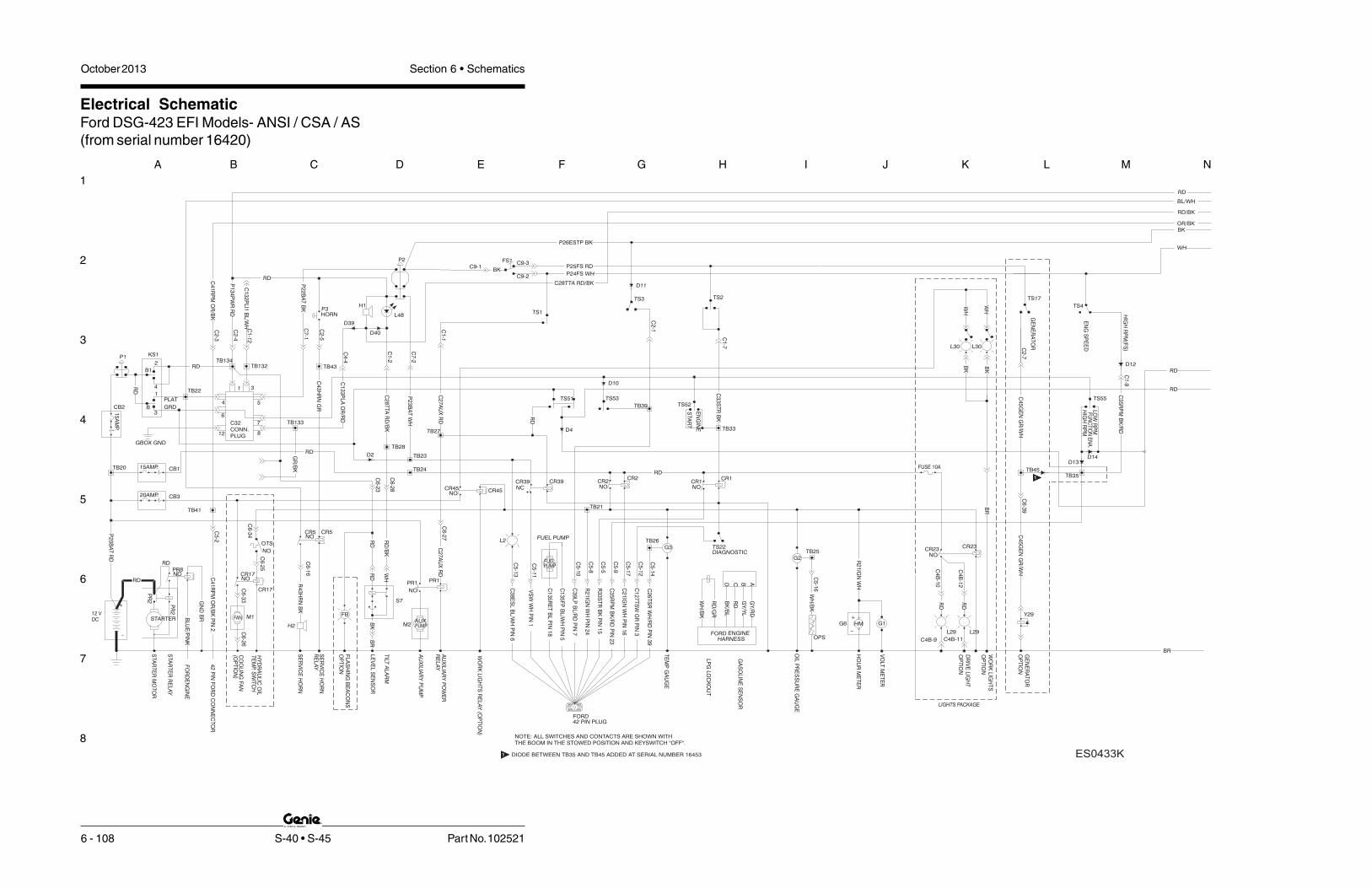
1
2
3
4
5
6
7
8
A B C D E F G H I J K L M N
October 2013 Section 6 • Schematics
6 - 108 S-40 • S-45 Part No. 102521
Electrical SchematicFord DSG-423 EFI Models- ANSI / CSA / AS(from serial number 16420)
C32CONN.PLUG
LIGHTS PACKAGE
WO
RK
LIG
HT
S
OP
TIO
N
DR
IVE
LIG
HT
OP
TIO
N
L29 L29
C4B-9 C4B-11
CR23NO
CR23
C4
B-1
0
C4
B-1
2
RD
RD
BR
FUSE 10A
WH
WH
BK
BK
L30 L30
FORD42 PIN PLUG
DIAGNOSTIC
BLU
E/P
INK
EN
GIN
EF
OR
D
C1
35
RE
TB
LP
IN1
8
C1
35
FP
BL/W
HP
IN5
GA
SO
LIN
ES
EN
SO
R
GY
/RD
GY
/YL
RD
BK
/BL
D C B A
C5
-8R
21
IGN
WH
PIN
24
42
PIN
FO
RD
CO
NN
EC
TO
RC
41
RP
MO
R/B
KP
IN2
C5
-13
C5
-9
C5
-17
C5
-5
C5
-12
C5
-10
C5
-11
CR2
NOCR2
R3
3S
TR
BK
PIN
15
C2
1IG
NW
HP
IN1
6
VS
WW
HP
IN1
TB24
CR39NCCR39
C3
5R
PM
BK
/RD
PIN
23
C1
27
TS
WG
RP
IN3
TS22
C3
8E
SL
BL/W
HP
IN6
C3
9LP
BL/R
DP
IN7
TS3
TS53
TB39
C2
-1
PUMPFUEL
FUEL PUMP
RD
/GR
HARNESSENGINEFORD
LP
GLO
CK
OU
TW
H/B
K
L2
C2
6T
SR
WH
/RD
PIN
39
C5
-14
CR1
NOCR1
STA
RT
ER
RE
LA
Y
D10
D11
GN
DB
R
BR
CR45NO
CR45
EN
GS
PE
ED
B1
B3
1
4
2
C2
7A
UX
RD
P2
0B
AT
RD
RD
Y29
G6
PR
2
PR
2
M2
S7
M1
HIG
HR
PM
(FS
)
TS4
TS17
C6
-26
C6
-39
WH
/BK
FUN
CTIO
NE
NA
.
L48
C2
-3
C28TTA RD/BK
P2
RD
P3H1
C7
-1
HORN
P2
2B
AT
BK
C2
-4P
13
4P
WR
RD
RD
KS1
GRD
PLAT
TB22
RD
P1TB134
C6
-25
C6
-34
C6
-33
20AMP. CB3
CR17
NOCR17
OTS
NO
HY
DR
AU
LIC
OIL
TE
MP.
SW
ITC
H
CO
OLIN
GFA
N(O
PT
ION
)
C5
-2
C6
-16
TB43
C6
-23
C6
-28
C6
-27
C5
-16
TE
MP
GA
UG
E
OIL
PR
ES
SU
RE
GA
UG
E
VO
LTM
ET
ER
G1
G3
G2
GE
NE
RA
TO
R
C1
-9
TS55
LOW
RP
M
HIG
HR
PM
C3
5R
PM
BK
/RD
P26ESTP BK
P25FS RD
P24FS WH
TS2
C2
-7C
45
GE
NG
R/W
H
C1
-7
TS52
TB33
C3
3S
TR
BK
TS1
C1
-1
C7
-2
C1
-2
TS51
C2
-5
TB27
RD
TB28
TB23
C4
3H
RN
GR
C2
7A
UX
RD
C2
8T
TA
RD
/BK
P2
3B
AT
WH
CB1
15
AM
P.
RD
CB2
TB20 15AMP.
C4
1R
PM
OR
/BK
TB41
FB
TB21R
21
IGN
WH
TB26
TB25
OPS
+
GE
NE
RA
TO
R
OP
TIO
N
OP
TIO
N
FLA
SH
ING
BE
AC
ON
S
_
HO
UR
ME
TE
R
PR1
NO
WH
RD
PR1
CR5NOCR5
R4
3H
RN
BK
RD
/BK
RD
+
DC12 V
BK PUMP
TILT
ALA
RM
LE
VE
LS
EN
SO
R
RE
LA
Y
SE
RV
ICE
HO
RN
SE
RV
ICE
HO
RN
RE
LA
Y
AU
XIL
IAR
YP
OW
ER
AU
XIL
IAR
YP
UM
P
-
H2
STA
RT
ER
MO
TO
R
RD
BL/WH
RD/BK
OR/BKBK
WH
BR
RD
RD
D13D14
D12
D4
D40
D2
C9-3
C9-2
FS1
BKC9-1
RD
TB132
C1
-12
C1
32
PLI1
BL/W
H D39
C1
33
PLA
OR
/RD
C4
-4
TB133
C4
5G
EN
GR
/WHPR8
NO
RD
WO
RK
LIG
HT
SR
ELA
Y(O
PT
ION
)
TB35TB45
STA
RT
EN
GIN
E
HMAUXSTARTER
GBOX GND
12
6
4
8
7
5
31
GR
/BK
NOTE: ALL SWITCHES AND CONTACTS ARE SHOWN WITHTHE BOOM IN THE STOWED POSITION AND KEYSWITCH "OFF".
FAN
ES0433KDIODE BETWEEN T 35 AND TB45 ADDED AT SERIAL NUMBER 16453B21
21

1
2
3
4
5
6
7
8
N M L K J I H G F E D C B A
Part No. 102521 S-40 • S-45 6 - 109
October 2013 Section 6 • Schematics
Electrical SchematicFord DSG-423 EFI Models- ANSI / CSA / AS
(from serial number 16420)
CR13NC
GR
/BK
-44
TS8
BR
C2
-6
TB44
TS58
JD
ALA
RM
GR
/BK
JIB
VA
LVE
S
CR13
JIB
VA
LVE
GR/WH
-
+
JIB TIME DELAY CIRCUIT
CR14NO
C1
7JU
GR
C1
8JD
GR
/BK
C1
8JD
GR
/BK
C1
7JU
GR
D2
8
D2
7
BR
GR
OU
ND
WH
J1 J1
PW
R
XO
UT
YO
UT
5 62 3 4
JC2 GN
D1
PRI UP/DN & TT ROTATE
OR
1 2
11
12
BR
N
RD
/WH
WH
/RD
XO
UT
BL/W
H
JC3 GN
D
PW
R
YO
UT
RK
OU
T
14
13 45
BL/W
H
WH
/RD
OR
BR
N
DRIVE & STEERING
5421 3 6
MO
TO
RS
TR
OK
E
Y27
C2
9M
SR
D/W
HC
5-2
4C
1-3
Y51Y2Y3Y4Y23Y29Y13Y22Y21Y12H4Y25Y26Y20Y19Y16Y17
7.5
C1
5P
LD
OR
/BK
C1
4P
LU
OR
C6
-19
CD
BA
C8
PB
RB
K/W
H
C7
PB
EB
K
C3
PB
FR
D/W
H
C2
PB
DR
D/B
K
C1
PB
UR
D
C4
TR
LW
H
C5
TR
RW
H/B
K
C6
TR
FW
H/R
D
C3
6S
TC
BL
C3
7S
TC
CB
L/B
K
C3
2B
RK
WH
/RD
C3
0E
DC
+W
H
C3
1E
DC
-W
H/B
K
C6
-14
C6
-15
C6
-40
C6
-13
C6
-32
5
L1TS15
158167
J1
6
DR
ELE
DB
L/R
D
DR
EB
BL/B
K
DR
EA
BL/W
H
96
J2
C2
-3
BR
-2
C1
-5
C1
-4
C1
-10
C1
-11
C1
-6
C3
-5
C3
-4
C3
-6
C3
-1
TS62 C4
TR
LW
H
TS61
C1
PB
UR
D
TB30TB31
TB36
TB37 TB32TB4
TB5TB2
TB1
C6
-5
C6
-1
TB3 TB6
C5
TR
RW
H/B
K
C3
1E
DC
-W
H/B
K
C3
7S
TC
CB
L/B
K
C3
6S
TC
BL
C6
TR
FW
H/R
D
C3
2B
RK
WH
/RD
C3
0E
DC
+W
H
10
11
1817 20
19
15
16
C4
1R
PM
OR
/BK
78
243 1
J3
3P
26
ES
TP
BK
P2
4F
SW
H
P2
4F
SW
H
4
DRIVELIFT/
OPTION
CE
TS13
JOYSTICK CONTROL CARD
WH
TS7TS9
C3
-3
C3
-2
C4
-1
TS63
C1
3D
RE
BL/R
D
C2
-2
C3
-8
C3
-7
C4
-3
C4
-2
C4
0LS
1O
R
C8
PB
RB
K/W
H
C7
PB
EB
K
TB40 TB13TB7
TB8
C6
-7
TB14
C1
5P
LD
OR
/BK
C1
4P
LU
OR
C2
PB
DR
D/B
K
C3
PB
FR
D/W
H
C4
-6
C4
-5
TS57
C4
-7C
19
JS
VG
R/W
H
TB15
C6
-17
TB18TB17
TB19
TS59
12
13
14
H4
C5
-23
C5
-20
C6
-37
C6
-36
C5
-21
ST
EE
RC
CW
ST
EE
RC
W
FLO
WC
ON
TR
OL
PR
IMA
RY
BO
OM
UP
PR
IMA
RY
BO
OM
FLO
WC
ON
TR
OL
TU
RN
TA
BLE
RO
TA
TE
TU
RN
TA
BLE
RO
TA
TE
CC
W
TU
RN
TA
BLE
RO
TA
TE
CW
PR
IMA
RY
BO
OM
DO
WN
DR
IVE
ED
CF
OR
WA
RD
DR
IVE
ED
CR
EV
ER
SE
TR
AV
EL
ALA
RM
OP
TIO
N
BR
AK
ER
ELE
AS
EV
ALV
E
BO
OM
EX
TE
ND
PLA
TLE
VE
LD
OW
N
PLA
TLE
VE
LU
P
PLA
TF
OR
MR
OTA
TE
CW
/JIB
UP
PLA
TF
OR
MR
OTA
TE
CC
W/
JIB
DO
WN
DE
SC
EN
TA
LA
RM
BO
OM
RE
TR
AC
T
C6
-18
C6
-8
C6
-3
C6
-2
C6
-6
C6
-4
TB29
C2
9M
SR
D/W
H
C6
-30
R2R1
5
CR27NC
NOCR30
TS14
DR
IVE
SP
EE
D
HI LO
C2
9M
SR
D/W
H
RD
/BK
LS
1-P
RIM
AR
YB
OO
ME
XT
EN
D
C4
0LS
1O
R
C1
3D
RE
BL/R
D
SJ1-WH
D29 D30
DR
IVE
LIM
ITS
WIT
CH
DR
IVE
LIM
ITS
WIT
CH
LS
2-P
RIM
AR
YB
OO
MU
P
LIM
ITS
WIT
CH
DR
IVE
EN
AB
LE
DR
IVE
EN
AB
LE
UP
DO
WN
PR
IMA
RY
BO
OM
EX
TE
ND
RE
TR
AC
TB
OO
M
DO
WN
UP
JIBB
OO
M
EX
TE
ND
RE
TR
AC
TB
OO
M
UP
DO
WN PLA
TF
OR
MLE
VE
L
DO
WN
UP
JIB
BO
OM
CC
W
CW
PLA
TR
OTA
TE
UP
DO
WN PLA
TF
OR
MLE
VE
L
CC
W
CW
PLA
TR
OTA
TE
34 WH
BK
NC
21
NO
13
22
14 14
22
13NO
21
NC
BK
WH
2 1 2 1WH
BK
NC
21
NO
13
22
14
NOTE: ALL SWITCHES AND CONTACTS ARE SHOWN WITHTHE BOOM IN THE STOWED POSITION AND KEYSWITCH "OFF".
BR
RD
RD
WH
BKOR/BK
RD/BK
RD
BL/WH

October 2013 Section 6 • Schematics
6 - 110
Electrical SchematicFord DSG-423 EFI Models- ANSI / CSA / AS(from serial number 16420)
6 - 109

October 2013Section 6 • Schematics
6 - 111
Electrical SchematicFord DSG-423 EFI Models- CE
(from serial number 16420)
6 - 112

1
2
3
4
5
6
7
8
A B C D E F G H I J K L M N
October 2013 Section 6 • Schematics
6 - 112 S-40 • S-45 Part No. 102521
Electrical SchematicFord DSG-423 EFI Models- CE(from serial number 16420)
LOADSENSEMODULE
U33
2 SEC
U35
NO30A
PBOX GND
U34
10ANO
2 SEC
OP
TIO
N
DR
IVE
LIG
HT
OP
TIO
N
WO
RK
LIG
HT
S
LIGHTS PACKAGE
RD
RD
C4
B-1
2
C4
B-1
0
CR23
NOCR23
C4B-11C4B-9
L29L29
FUSE 10A
BR
L30L30
BK
BK
WH
WH
STA
RT
ER
RE
LA
Y
CR1NO
CR1
C5
-14
L2
LP
GLO
CK
OU
T
FORDENGINEHARNESS
FUEL PUMP
FUELPUMP
C2
-1
TB39
TS53
TS3
TS22
CR39NC
CR39
TB24
CR2NO
CR2
C5
-11
C5
-10
C5
-12
C5
-5
C5
-17
C5
-9
C5
-13
42
PIN
FO
RD
CO
NN
EC
TO
R
C5
-8
ABCD
GA
SO
LIN
ES
EN
SO
R
FO
RD
EN
GIN
E
DIAGNOSTIC
42 PIN PLUGFORD
WH
/BK
RD
/GR
BK
/BL
RD
GY
/YL
GY
/RD
D10
D11
C2
6T
SR
WH
/RD
PIN
39
C3
9LP
BL/R
DP
IN7
C3
8E
SL
BL/W
HP
IN6
C1
27
TS
WG
RP
IN3
C3
5R
PM
BK
/RD
PIN
23
VS
WW
HP
IN1
C2
1IG
NW
HP
IN1
6
R3
3S
TR
BK
PIN
15
R2
1IG
NW
HP
IN2
4
C1
35
FP
BL/W
HP
IN5
C1
35
RE
TB
LP
IN1
8
C4
1R
PM
OR
/BK
PIN
2
BLU
E/P
INK
GN
DB
R
BR
CR45NOCR45
STA
RT
ER
MO
TO
R
H2
-
AU
XIL
IAR
YP
UM
P
AU
XIL
IAR
YP
OW
ER
RE
LA
YS
ER
VIC
EH
OR
N
SE
RV
ICE
HO
RN
RE
LA
Y
LE
VE
LS
EN
SO
R
TILT
ALA
RM
PUMP
BK
12 VDC
+
RD
/BK
R4
3H
RN
BK
CR5NO
CR5
PR1
RD
WH
NO
PR1
HO
UR
ME
TE
R
_
FLA
SH
ING
BE
AC
ON
S
OP
TIO
N
OP
TIO
N
GE
NE
RA
TO
R
+
OPS
TB25
TB26
R2
1IG
NW
H
TB21
FB
TB41
C4
1R
PM
OR
/BK
15AMP.TB20
CB2
RD
15
AM
P.
CB1
P2
3B
AT
WH
C2
8T
TA
RD
/BK
C2
7A
UX
RD
C4
3H
RN
GR
TB23
TB28
RD
TB27
C2
-5
TS51
C1
-2
C7
-2
TS1
C3
3S
TR
BK
TB33
TS52
C1
-7
C4
5G
EN
GR
/WH
C2
-7
TS2
P24FS WH
P25FS RD
P26ESTP BKC
35
RP
MB
K/R
D
HIG
HR
PM
LO
WR
PM
TS55
C1
-9
GE
NE
RA
TO
R
G2
G3
G1
VO
LTM
ET
ER
OIL
PR
ES
SU
RE
GA
UG
E
TE
MP
GA
UG
E
C5
-16
C6
-27
C6
-28
C6
-23
TB43
C6
-16
C5
-2
(OP
TIO
N)
CO
OLIN
GFA
N
TE
MP.
SW
ITC
HH
YD
RA
ULIC
OIL
NO
OTS
CR17NO
CR17
CB320AMP.
C6
-33
C6
-34
C6
-25
TB134P1
RD
TB22
PLAT
GRD
KS1
RD
P1
34
PW
RR
DC
2-4
P2
2B
AT
BK
HORN
C7
-1
P3
RD
P2
C2
8T
TA
RD
/BK
C2
-3
FU
NC
TIO
NE
NA
.
WH
/BK
C6
-39
C6
-26
TS17
TS4
HIG
HR
PM
(FS
)
M1
S7
M2
PR
2
PR
2
G6
Y29
RD
P2
0B
AT
RD
C2
7A
UX
RD
2
4
1
3B
B1
EN
GS
PE
ED
C1
-1
D39
D40
L4
TB132
C1
-12
C1
32
PLI1
BL/W
H
C132PLI2 BK
R24PWR
P24PWR
WH
BKOR/BK
RD/BK
BL/WH
RD
BR
RD
RD
D13D14
D12
D2
D4
BK
C9-3
C9-2
FS1
BKC9-1
TB133
GR
/BK
C4
-4C
13
3P
LA
OR
/RD
RD
C4
5G
EN
GR
/WHNO
PR8
RD
WO
RK
LIG
HT
RE
LA
Y(O
PT
ION
)
TB35TB45
STARTER AUX HM
STA
RT
EN
GIN
E
-H1
+
L45
GN
/BK
H6
D88PBOX
LS18
LS18AD89
C3
-10
R204.7K
GBOX GND
812
7
6
4 5
31
GND
NOTE: ALL SWITCHES AND CONTACTS ARE SHOWN WITHTHE BOOM IN THE STOWED POSITION AND KEYSWITCH "OFF".
FAN
DIODE BETWEEN T 35 AND TB45 ADDED AT SERIAL NUMBER 16453B21
21

1
2
3
4
5
6
7
8
N M L K J I H G F E D C B A
Part No. 102521 S-40 • S-45 6 - 113
October 2013 Section 6 • Schematics
Electrical SchematicFord DSG-423 EFI Models- CE
(from serial number 16420)
CR13NC
GR
/BK
-44
TS8
BR
C2
-6
TB44
TS58
JD
ALA
RM
GR
/BK
JIB
VA
LVE
S
CR13
JIB
VA
LVE
GR/WH
-
+
JIB TIME DELAY CIRCUIT
CR14NO
C1
7JU
GR
C1
8JD
GR
/BK
C1
8JD
GR
/BK
C1
7JU
GR
D2
8
D2
7
BR
GR
OU
ND
WH
J1 J1
PW
R
XO
UT
YO
UT
5 62 3 4
JC2 GN
D1
PRI UP/DN & TT ROTATE
OR
1 2
11
12
BR
N
RD
/WH
WH
/RD
XO
UT
BL/W
H
JC3 GN
D
PW
R
YO
UT
RK
OU
T
14
13 45
BL/W
H
WH
/RD
OR
BR
N
DRIVE & STEERING
5421 3 6
MO
TO
RS
TR
OK
E
Y27
C2
9M
SR
D/W
HC
5-2
4C
1-3
Y51Y2Y3Y4Y23Y29Y13Y22Y21Y12H4Y25Y26Y20Y19Y16Y17
7.5
C1
5P
LD
OR
/BK
C1
4P
LU
OR
C6
-19
CD
BA
C8
PB
RB
K/W
H
C7
PB
EB
K
C3
PB
FR
D/W
H
C2
PB
DR
D/B
K
C1
PB
UR
D
C4
TR
LW
H
C5
TR
RW
H/B
K
C6
TR
FW
H/R
D
C3
6S
TC
BL
C3
7S
TC
CB
L/B
K
C3
2B
RK
WH
/RD
C3
0E
DC
+W
H
C3
1E
DC
-W
H/B
K
C6
-14
C6
-15
C6
-40
C6
-13
C6
-32
5
L1TS15
158167
J1
6
DR
ELE
DB
L/R
D
DR
EB
BL/B
K
DR
EA
BL/W
H
96
J2
C2
-3
BR
-2
C1
-5
C1
-4
C1
-10
C1
-11
C1
-6
C3
-5
C3
-4
C3
-6
C3
-1
TS62 C4
TR
LW
H
TS61
C1
PB
UR
D
TB30TB31
TB36
TB37 TB32TB4
TB5TB2
TB1
C6
-5
C6
-1
TB3 TB6
C5
TR
RW
H/B
K
C3
1E
DC
-W
H/B
K
C3
7S
TC
CB
L/B
K
C3
6S
TC
BL
C6
TR
FW
H/R
D
C3
2B
RK
WH
/RD
C3
0E
DC
+W
H
10
11
1817 20
19
15
16
C4
1R
PM
OR
/BK
78
243 1
J3
3P
26
ES
TP
BK
P2
4F
SW
H
P2
4F
SW
H
4
DRIVELIFT/
OPTION
CE
TS13
JOYSTICK CONTROL CARD
WH
TS7TS9
C3
-3
C3
-2
C4
-1
TS63
C1
3D
RE
BL/R
D
C2
-2
C3
-8
C3
-7
C4
-3
C4
-2
C4
0LS
1O
R
C8
PB
RB
K/W
H
C7
PB
EB
K
TB40 TB13TB7
TB8
C6
-7
TB14
C1
5P
LD
OR
/BK
C1
4P
LU
OR
C2
PB
DR
D/B
K
C3
PB
FR
D/W
H
C4
-6
C4
-5
TS57
C4
-7C
19
JS
VG
R/W
H
TB15
C6
-17
TB18TB17
TB19
TS59
12
13
14
H4
C5
-23
C5
-20
C6
-37
C6
-36
C5
-21
ST
EE
RC
CW
ST
EE
RC
W
FLO
WC
ON
TR
OL
PR
IMA
RY
BO
OM
UP
PR
IMA
RY
BO
OM
FLO
WC
ON
TR
OL
TU
RN
TA
BLE
RO
TA
TE
TU
RN
TA
BLE
RO
TA
TE
CC
W
TU
RN
TA
BLE
RO
TA
TE
CW
PR
IMA
RY
BO
OM
DO
WN
DR
IVE
ED
CF
OR
WA
RD
DR
IVE
ED
CR
EV
ER
SE
TR
AV
EL
ALA
RM
OP
TIO
N
BR
AK
ER
ELE
AS
EV
ALV
E
BO
OM
EX
TE
ND
PLA
TLE
VE
LD
OW
N
PLA
TLE
VE
LU
P
PLA
TF
OR
MR
OTA
TE
CW
/JIB
UP
PLA
TF
OR
MR
OTA
TE
CC
W/
JIB
DO
WN
DE
SC
EN
TA
LA
RM
BO
OM
RE
TR
AC
T
C6
-18
C6
-8
C6
-3
C6
-2
C6
-6
C6
-4
TB29
C2
9M
SR
D/W
H
C6
-30
R2R1
5
CR27NC
NOCR30
TS14
DR
IVE
SP
EE
D
HI LO
C2
9M
SR
D/W
H
RD
/BK
LS
1-P
RIM
AR
YB
OO
ME
XT
EN
D
C4
0LS
1O
R
C1
3D
RE
BL/R
D
SJ1-WH
D29 D30
DR
IVE
LIM
ITS
WIT
CH
DR
IVE
LIM
ITS
WIT
CH
LS
2-P
RIM
AR
YB
OO
MU
P
LIM
ITS
WIT
CH
DR
IVE
EN
AB
LE
DR
IVE
EN
AB
LE
UP
DO
WN
PR
IMA
RY
BO
OM
EX
TE
ND
RE
TR
AC
TB
OO
M
DO
WN
UP
JIBB
OO
M
EX
TE
ND
RE
TR
AC
TB
OO
M
UP
DO
WN PLA
TF
OR
MLE
VE
L
DO
WN
UP
JIB
BO
OM
CC
W
CW
PLA
TR
OTA
TE
UP
DO
WN PLA
TF
OR
MLE
VE
L
CC
W
CW
PLA
TR
OTA
TE
34 WH
BK
NC
21
NO
13
22
14 14
22
13NO
21
NC
BK
WH
2 1 2 1WH
BK
NC
21
NO
13
22
14
NOTE: ALL SWITCHES AND CONTACTS ARE SHOWN WITHTHE BOOM IN THE STOWED POSITION AND KEYSWITCH "OFF".
BR
RD
RD
WH
BKOR/BK
RD/BK
RD
BL/WH

October 2013 Section 6 • Schematics
6 - 114
Electrical SchematicFord DSG-423 EFI Models- CE(from serial number 16420)
6 - 113

October 2013Section 6 • Schematics
6 - 115
Ground Control Box Wiring DiagramFord DSG-423 EFI Models
(before serial number 14832)
6 - 116

1
2
3
4
5
6
7
8
A B C D E F G H I J K L M N
October 2013 Section 6 • Schematics
6 - 116 S-40 • S-45 Part No. 102521
ALL BR WIRES
GROUND STUD
BR
BR-GND STUD
BK-22C
WH-23C
HARNESS:TO BASE
WIRING
GR
OU
ND
ST
UD
B
B1
1
24
3
RD
KEY SWITCH
KS1
44B-RD/BK-C6-19
12
V
EN
GIN
E1
9/1
8C
AB
LE
SF
UN
CT
ION
S1
2V
TO
PL
AT
C5
C6
(GY
)
C1
B
(BR
)
C4
B
(GR
)
C3
B
(BK
)
C2
BC
7B 1
2
3
R2
AD ABCD
WH-23B
RD-27B
GR-C5-12
BK-C5-5
TS22
BK-22B
GR-43B
CR5
BK-C6-16
WH-C5-17
WH-21B
BK-33B
RD-24B
CR1 CR2
C B
OR-C6-33
CR39
RD-CB3 SP
BK-C6-25
WH-C5-11
CR17
RD- 20B
RD- P1 E-STOP
OR/BK-15A
GR/WH-19A
GR/BK-18A
GR-17A
OR-14A
BK/RD-35A
RD- 20A
RD- 24A
TS55
TS52
RD-CR17/CR23 #30
WH-4AWH/RD-6AWH/BK-5A
GR/BK-44A
RD- 20C
BK-7A
BK/WH-8A
BK-33A
CB1 CB2
CB3
D5
35BK/RD-C5-9 BK/RD-C1B-9
GR/BK-C6-18 GR/BK-C4B-6
BL/WH-C3B-12
BL/RD-C4B-1
OR/BK-C4B-3
OR-C4B-2
OR/RD-C4B-4
GR-C4B-5
RD/BK-C3B-2
RD-C3B-1
BK-C3B-7
WH/RD-C3B-6
WH/BK-C3B-5
WH-C3B-4
RD/WH-C3B-3
BK/RD-C3B-9
BK/WH-C3B-8
BL-C3B-10
BL/BK-C3B-11
RD/BK-C6-2
BK- C6-7
WH/RD-C6-6
WH- C6-4
RD/WH-C6-3
WH/BK-C6-5
BK/WH-C6-8
RD- C6-1
OR/BK-C6-15
OR- C6-14
BL/RD-C6-13
GR- C6-17
9
1
2
4
3
5
6
7
8
13
11
10
12
14
15
17
16
RD-S.P.(CB3)
BK-C1B-7
BK/WH-C1B-8
WH-C6-34
BK-C7B-1
GR/WH-C4B-7
RD/BK-C1B-2
WH-C7B-2
RD-C1B-1
RD/WH-C1B-3
WH-C1B-4
WH/BK-C1B-5
WH/RD-C1B-6
WH/RD-C5-14
RD- 12 VOLT
WH/BK-C5-16
BL/WH-C6-30
RD- C6-23
WH-C5-3+C5-8
RD/WH-C5-24
WH/RD-C5-23
WH- C5-21
WH/BK-C5-20
RD/BK-C6-28
RD- C6-27
22
20
18
19
21
24
23
26
25
BK-CR5#30
RD-S.P.(CB2)
WH-CR2#87
RED-CR1#30
CR39 #30
27
28
30
29
33
31
32
34
RD-CR39#85
BK-CR1#85
GR-C2B-5
BL/WH-C1B-12
BL-C1B-10
BL/BK-C1B-11
RD-C2B-4
OR-C2B-2
BL/RD-C2B-1
OR/BK-C2B-3
GR/WH-C2B-7
GR/BK-C2B-6
BL/BK-C6-37
BL- C6-36
OR/BK-C5-2
OR- C6-40
BL/RD-C5-10
GR/WH-C6-39
GR/BK-2B
37
36
38
39
41
40
43
42
GR-CR5#85
46
45
44
BK/RD-S.P. RPM
GR/BK-S.P.
DRV. ENA. LT.
PLAT. ROT. L.
PLAT. LEVEL DN.
PLAT. LEVEL. UP
PRI. BOOM UP
BOOM RETRACT
BOOM EXTEND
TURN. ROT. F.C.
TURN. ROT. R
PRI. BOOM F.C.
PRI. BOOM DOWN
TURN. ROT. L
BK-S.P.
BK/WH-S.P.
WH-S.P.
RD/BK-S.P.
WH/BK-S.P.
RD/WH-S.P.
WH/RD-S.P.
RD-S.P.
GR-S.P.
OR-S.P.
OR/BK-S.P.
C133PLT
12V BATTERY SUPPLY
MOTOR SPEED
WATER TEMP. SENDER
OIL PRESSURE SENDER
BRAKE/TRAVEL ALARM
GLOW PLUG
ENGINE POWER
PWR. TO PLAT.
KEYSWITCH PWR/FB
AUX. PWR.
TILT ALARM
IGNITION PWR.
PLAT. ROT. R.
JIB VALVE
WH/RD-S.P.
RD-S.P.(CB1)
BK-S.P.
WH-S.P.
WH/BK-S.P.
GR/WH-SP
WH-S.P.
RD-S.P.
BK/WH-S.P.
RD-S.P.
BK-S.P.
E.D.C.+
START
E.D.C.-
HM
BL/WH-C5-13
RD/WH-3A
RD-1A
RD/BK-2A
BR (GROUND)
WH-21A
R3
L2 TS53
NC
NC
BL/RD-39A
RD-42ARD-27A
RD-CB2
WH-23A
WH/RD-26A
WH/BK-25A
BK-22A
P1
JDALARM JIB
GEN. OPTION
PULSE PICKUP
STEER RIGHT
STEER LEFT
LIMIT SWITCH SIG.
C134PWR
GR/BK-S.P.
RD-KS1-2 S.P.
BL/RD-S.P.
C132PLI
L.P.
HORN
SPARE
G1
BR (GROUND)
WH-21A
G2
TS57
TS59
R1
TS58
TS63
TS62
TS61
TS51
G3
13480TS51AUXILIARY SWITCH
RESISTOR, 1K OHM/2W, CHECK ENGINE
LP/GAS SWITCH
PLATFORM ROTATE SWITCH
FUNCTION ENABLE
ENGINE START SWITCH
VOLT METER GAGE
TURNTABLE ROTATE SWITCH
CHECK ENGINE SWITCH
HOUR METER
WATER TEMP. GAGE
CHECK ENGINE (after serial number 13739)
OIL PRESSURE GAGE
RESISTOR, 5 OHM, BOOM FUNCTION
CIRCUIT BREAKER, OPTIONS, 20A
RESISTOR, 7.5 OHM,TURNTABLE FUNCT
BOOM EXTEND/RETRACT SWITCH
CIRCUIT BREAKER, ENGINE, 15A
CIRCUIT BREAKER, CONTROLS, 15A
PRIMARY BOOM UP/DOWN SWITCH
JIB BOOM UP/DOWN SWITCH
PLATFORM LEVEL SWITCH
R1R1
G3
R3
HM
L2
G1
G2
R2
G3
104333
119870
HM
G1
G2
R2
16397TS61
TS58
TS22
TS62
CB3
CB2
CB1
CB2
CB3
CB1
42730
13037
16397
TS52
TS53
TS57
TS55
TS63
TS59
16397
13037
13037
13037
13037
56457
DESCRIPTION
KEY SWITCH
EMERGENCY STOP BUTTON
LABEL
P1
KS1
PART#
KS1
P1
WH/RD-C6-32
BK/RD-CR23#86 DRIVE LIGHT OPTION
DRIVE LIGHT OPTION RELAY
CR23
BRN GND
RD-CB3 S.P.
BK/RD-9B
RD C4B-12
RD C4B-11
ESO433
L2 110395CHECK ENGINE (before serial number 13740)
B
B1
1
24
3
RD
KEY SWITCH KS1
BL/WH-C5-13
L2
WH-23A
Check Engine Light
(after serial number 13739)
Note: Removed resistor R3 and
changed L2 to incandescent
Ground Control Box Wiring DiagramFord DSG-423 EFI Models(before serial number 14832)
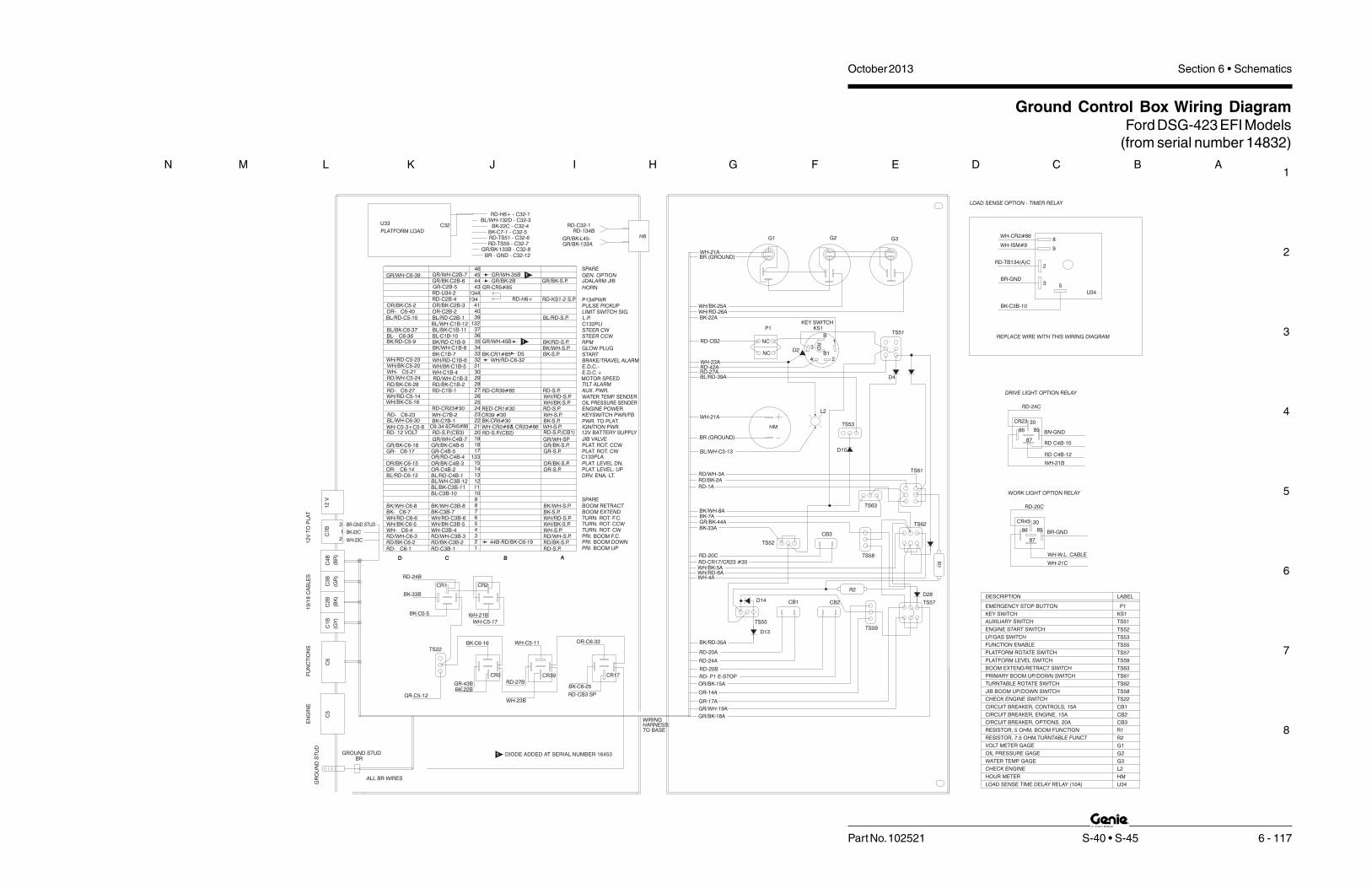
1
2
3
4
5
6
7
8
N M L K J I H G F E D C B A
Part No. 102521 S-40 • S-45 6 - 117
October 2013 Section 6 • Schematics
Ground Control Box Wiring DiagramFord DSG-423 EFI Models
(from serial number 14832)
3
2
1
C7
BC
2B
(BK
)
C3
B
(GR
)
C4
B
(BR
)
C1
B
(GY
)
C6
C5
12
VT
OP
LA
TF
UN
CT
ION
S1
9/1
8C
AB
LE
SE
NG
INE
12
V
WIRING
TO BASEHARNESS:
WH-23C
BK-22C
BR-GND STUD
BRGROUND STUD
ALL BR WIRES
2
U34
8
9
3 5
G3
TS51
TS61
TS62
TS63
TS58
R1
TS59
TS57
G2
WH-21ABR (GROUND)
G1
SPARE
HORN
L.P.C132PLI
BL/RD-S.P.
RD-KS1-2 S.P.
GR/BK-S.P.
P134PWR
LIMIT SWITCH SIG.
STEER CWSTEER CCW
PULSE PICKUP
GEN. OPTIONJDALARM JIB
P1
BK-22A
WH/BK-25AWH/RD-26A
WH-23A
RD-CB2
RD-27ARD-42A
BL/RD-39A
NC
NC
TS53
L2WH-21A
BR (GROUND)
RD/BK-2ARD-1A
RD/WH-3A
BL/WH-C5-13
HM
E.D.C.-
START
E.D.C.+
BK-S.P.
RD-S.P.
BK/WH-S.P.
RD-S.P.
WH-S.P.
GR/WH-SP
WH/BK-S.P.
WH-S.P.BK-S.P.
RD-S.P.(CB1)
WH/RD-S.P.
JIB VALVEPLAT. ROT. CCW
IGNITION PWR.
TILT ALARMAUX. PWR.
KEYSWITCH PWR/FBPWR. TO PLAT.
ENGINE POWER
GLOW PLUG
BRAKE/TRAVEL ALARM
OIL PRESSURE SENDERWATER TEMP. SENDER
MOTOR SPEED
12V BATTERY SUPPLY
C133PLA
OR/BK-S.P.OR-S.P.
GR-S.P.
RD-S.P.
WH/RD-S.P.
RD/WH-S.P.
WH/BK-S.P.
RD/BK-S.P.
WH-S.P.
BK/WH-S.P.BK-S.P.
TURN. ROT. CW
PRI. BOOM DOWNPRI. BOOM F.C.
TURN. ROT. CCWTURN. ROT. F.C.BOOM EXTENDBOOM RETRACT
PRI. BOOM UP
PLAT. LEVEL. UPPLAT. LEVEL DN.
PLAT. ROT. CW
DRV. ENA. LT.
GR/BK-S.P.
RPMBK/RD-S.P.
444546
GR-CR5#85
134
43
4041
39132
3637
GR/BK-2BGR/WH-C6-39
BL/RD-C5-10OR- C6-40OR/BK-C5-2
BL- C6-36BL/BK-C6-37
GR/BK-C2B-6GR/WH-C2B-7
OR/BK-C2B-3
BL/RD-C2B-1OR-C2B-2
RD-C2B-4
BL/BK-C1B-11BL-C1B-10
BL/WH-C1B-12
GR-C2B-5
BK-CR1#85
RD-CR39#85
34
3231
33
2930
2827
CR39 #30RED-CR1#30
WH-CR2#87RD-S.P.(CB2)
BK-CR5#30
2526
2324
21
1918
20
22
RD- C6-27RD/BK-C6-28
WH/BK-C5-20WH- C5-21
WH/RD-C5-23
RD/WH-C5-24
WH-C5-3+C5-8
RD- C6-23BL/WH-C6-30
WH/BK-C5-16
RD- 12 VOLT
WH/RD-C5-14
WH/RD-C1B-6WH/BK-C1B-5WH-C1B-4RD/WH-C1B-3
RD-C1B-1
WH-C7B-2
RD/BK-C1B-2
GR/WH-C4B-7
BK-C7B-1C6-34
BK/WH-C1B-8BK-C1B-7
RD-S.P.(CB3)
13317
1514
12
1011
13
8765
34
2
1
9
GR- C6-17
BL/RD-C6-13OR- C6-14OR/BK-C6-15
RD- C6-1
BK/WH-C6-8
WH/BK-C6-5
RD/WH-C6-3WH- C6-4
WH/RD-C6-6BK- C6-7
RD/BK-C6-2
BL/BK-C3B-11BL-C3B-10
BK/WH-C3B-8
RD/WH-C3B-3WH-C3B-4WH/BK-C3B-5WH/RD-C3B-6BK-C3B-7
RD-C3B-1RD/BK-C3B-2
GR-C4B-5OR/RD-C4B-4
OR-C4B-2OR/BK-C4B-3
BL/RD-C4B-1BL/WH-C3B-12
GR/BK-C4B-6GR/BK-C6-18
BK/RD-C1B-9BK/RD-C5-9 35
D5
CB3
CB2CB1
BK-33A
BK/WH-8ABK-7A
RD-20C
GR/BK-44A
WH/BK-5AWH/RD-6AWH-4A
RD-CR17/CR23 #30
TS52
TS55
RD-24A
RD-20A
BK/RD-35A
OR-14A
GR-17A
GR/BK-18A
GR/WH-19A
OR/BK-15A
RD- P1 E-STOP
RD-20BCR17
WH-C5-11
BK-C6-25
RD-CB3 SP
CR39
OR-C6-33
BC
CR2CR1
RD-24B
BK-33B
WH-21B
WH-C5-17
BK-C6-16
CR5
GR-43BBK-22B
TS22
BK-C5-5
GR-C5-12
RD-27B
WH-23B
D C B AD A
R2
KS1
P1
LABEL
EMERGENCY STOP BUTTON
KEY SWITCH
DESCRIPTION
TS59
TS63
TS55
TS57
TS53
TS52
CB1
CB2
CB3
TS62
TS22
TS58
TS61
R2
G2
G1
L2
HM
G3
R1
PLATFORM LEVEL SWITCH
JIB BOOM UP/DOWN SWITCH
PRIMARY BOOM UP/DOWN SWITCH
CIRCUIT BREAKER, CONTROLS, 15A
CIRCUIT BREAKER, ENGINE, 15A
BOOM EXTEND/RETRACT SWITCH
RESISTOR, 7.5 OHM,TURNTABLE FUNCT
CIRCUIT BREAKER, OPTIONS, 20A
RESISTOR, 5 OHM, BOOM FUNCTION
OIL PRESSURE GAGE
CHECK ENGINE
WATER TEMP. GAGE
HOUR METER
CHECK ENGINE SWITCH
TURNTABLE ROTATE SWITCH
VOLT METER GAGE
ENGINE START SWITCH
FUNCTION ENABLE
PLATFORM ROTATE SWITCH
LP/GAS SWITCH
AUXILIARY SWITCH TS51
U34LOAD SENSE TIME DELAY RELAY (10A)
134ARD-U34-2RD-H6+
GR/WH-35B
GR/WH-45B
KS1KEY SWITCH
RD
B
B1
1
24
3
GR
OU
ND
ST
UD
D2
D4
D10
D28D14
D13
LOAD SENSE OPTION - TIMER RELAY
WH-CR2#86
WH-ISM#9
RD-TB134(A)C
BR-GND
BK-C3B-10
44B-RD/BK-C6-19
SPARE
RD-CR23#30
&CR45#86 & CR23#86
WH/RD-C6-32
REPLACE WIRE WITH THIS WIRING DIAGRAM
GR/BK-133B - C32-8
BK-C7-1 - C32-5BK-22C - C32-4
RD-TS55 - C32-7
RD-H6+ - C32-1
BR - GND - C32-12
RD-TS51 - C32-6
BL/WH-132D - C32-3
PLATFORM LOAD
U33 C32
GR/BK-133AGR/BK-L45-
RD-134BRD-C32-1
H6
85
30
86
87
85
30
86
87
CR45
RD-20C
WORK LIGHT OPTION RELAY
WH-W.L. CABLE
WH-21C
BR-GND
BN-GND
WH-21B
RD C4B-12
RD C4B-10
DRIVE LIGHT OPTION RELAY
RD-24C
CR23
DIODE ADDED AT SERIAL NUMBER 164531
1
1

October 2013 Section 6 • Schematics
6 - 118
Ground Control Box Wiring DiagramFord DSG-423 EFI Models(from serial number 14832)
6 - 117

October 2013Section 6 • Schematics
6 - 119
Platform Control Box Wiring DiagramFord DSG-423 EFI Models
(before serial number 14832)
6 - 120

1
2
3
4
5
6
7
8
A B C D E F G H I J K L M N
October 2013 Section 6 • Schematics
6 - 120 S-40 • S-45 Part No. 102521
Platform Control Box Wiring DiagramFord DSG-423 EFI Models(before serial number 14832)
D4
0
GR/BK C4P-4
BATGND C7P-3
RE
D/B
LK
-28
TILT
ALALRM
H1
RE
D-T
ILT
BR
N
D3
9
19/18 CONTROL CABLE
C2
P(B
K)
C1
P(G
Y)
C4
P(B
R)
C3
P(G
R)
12V BATT
C7P
C3P
C4P
C7P
C1
3L
ED
BL
/RD
C28TTA RD/BK C1P-2
C2
9M
SR
D/W
H
RE
D-T
ILT
GR
/BK
L4
8
JC1
-2B
RN
JC2
-2B
RN
JC3
-4,6
WH
JC3
-2B
RN
DR
EB
BL
/BK
DR
EA
BL
/WH
C2
7A
UX
RD
C1
P-1
C3
4S
AB
K/W
HC
1P
-8
C3
3S
TR
BK
C1
P-7
C2
8T
TA
RD
/BK
C1
P-2
C1P
C2P
1
RD
/BK
L4
J1
9
C1
0S
BU
BL
C3
P-1
0
C1
3D
RE
BL
/RD
C4
P-1
C11
SB
DB
L/B
KC
3P
-1 1
C4
0L
S1
OR
C2
P-2
C1
2S
BF
BL
/WH
C3
P-1
2
C4
1R
PM
OR
/BK
C2
P-3
C3
0E
DC
+W
HC
1P
-4
C1
PB
UR
DC
3P
-1
C3
1E
DC
-W
H/B
KC
1P
-5
C2
PB
DR
D/B
KC
3P
-2
C3
7S
TC
CB
L/B
KC
1P
-1 1
C3
PB
FR
D/W
HC
3P
-3
C3
6S
TC
BL
C1
P-1
0
C4
TR
LW
HC
3P
-4
C3
2B
RK
WH
/RD
C1
P-6
C5
TR
RW
H/B
KC
3P
-5
C2
9M
SR
D/W
HC
1P
-3
C3
5R
PM
BK
/RD
C1
P-9
C1
34
PW
RR
DC
2P
-4
J2
JC2
-5B
K
JC2
-3O
R
JC3
-5B
L
JC3
-3O
R
JC1
-5Y
EL
JC2
-4R
D
JC1
-3O
R
ALC-500
P2
4F
SW
H
BR
N
P2
4F
SW
H
C3P
C9P
F.S.
F.S.
JIBLS18
BR
N
C1
9JS
VG
R/W
HC
4P
-7A
ND
TS
8
OPT.
C4
5G
EN
GR
/WH
C2
P-7
P2
4F
SW
HC
9P
-2
P2
5F
SR
DC
9P
-3
P2
6B
AT
BK
C9
P-1
C7
PB
EB
KC
3P
-7
C8
PB
RB
K/W
HC
3P
-8
C4
3H
RN
GR
C2
P-5
JDA
LA
RM
GR
/BK
C2
P-6
DR
IVE
LTB
K/R
DC
3P
-9
C6
TR
FW
H/R
DC
3P
-6
1
11
1
C1
9JS
VG
R/W
HJIB
P2
3S
WB
AT
WH
C7
P-2
P2
2B
AT
BK
C7
P-1
C1
8JD
GR
/BK
C4
P-6
C1
32
PL
IB
KC
1P
-12
C1
5P
LD
OR
/BK
C4
P-3
C1
4P
LU
OR
C4
P- 2
C1
7JU
GR
C4
P-5
RD
H1
RD
P2
P2
6B
AT
BK
J3
3
HARNESS
PBOX WIRING
DL
ITE
BK
/RD
C3
P-9
TS
48
-WL
2R
DC
2P
-11
TS
48
-WL
1R
DC
2P
-12
C3
9L
PB
L/R
DC
2P
-1
ESO433

1
2
3
4
5
6
7
8
N M L K J I H G F E D C B A
Part No. 102521 S-40 • S-45 6 - 121
October 2013 Section 6 • Schematics
Platform Control Box Wiring DiagramFord DSG-423 EFI Models
(from serial number 14832)
TS
48
-WL1
RD
C2
P-1
2
TS
48
-WL2
RD
C2
P-1
1
C3
9LP
BL/R
DC
2P-1
BR
BR
B
RD
C1
CR14
GR/WH
P1
34
PW
RR
D
CR
13
-#8
6G
R/W
H
GR
/WH
RD
GR/WH
B
YY
B
RR
R
BR -
RD OUTPUT
GR/WH +
B
BK
JIB
R
B
BY Y
B
B
WH
B
B
3
J3
P2
6E
ST
PB
K
C1
7JU
GR
C4
P-5
C1
4P
LU
OR
C4
P-2
C1
5P
LD
OR
/BK
C4
P-3
C1
8JD
GR
/BK
C4
P-6
P2
2B
AT
BK
C7
P-1
P2
3B
AT
WH
C7
P-2
C1
9JS
VG
R/W
HC
4P-7
1
11
1
C6
TR
FW
H/R
DC
3P-6
JD
ALA
RM
GR
/BK
C2
P-6
C4
3H
RN
GR
C2
P-5
C8
PB
RB
K/W
HC
3P-8
C7
PB
EB
KC
3P-7
P2
6E
ST
PB
KC
9P-1
P2
5F
SR
DC
9P-3
P2
4F
SW
HC
9P-2
C4
5G
EN
GR
/WH
C2
P-7
F.S.
C9P
P2
4F
SW
H
BR
P2
4F
SW
HALC-500
J2
P1
34
PW
RR
DC
2P-4
C3
5R
PM
BK
/RD
C1
P-9
C2
9M
SR
D/W
HC
1P-3
C5
TR
RW
H/B
KC
3P-5
C3
2B
RK
WH
/RD
C1
P-6
C4
TR
LW
HC
3P-4
C3
6S
TC
BL
C1
P-1
0C
3P
BF
RD
/WH
C3
P-3
C3
7S
TC
CB
L/B
KC
1P-1
1
C2
PB
DR
D/B
KC
3P-2
C3
1E
DC
-W
H/B
KC
1P-5
C1
PB
UR
DC
3P-1
C3
0E
DC
+W
HC
1P-4
C4
1R
PM
OR
/BK
C2
P-3
C1
2S
BF
BL/W
HC
3P-1
2C
40
LS
1O
RC
2P-2
C1
1S
BD
BL/B
KC
3P-1
1C
13
DR
EB
L/R
DC
4P-1
C1
0S
BU
BL
C3
P-1
0
9
J1
RD
/BK
L4
1
C2P
C1P
C2
8T
TA
RD
/BK
C1
P-2
C3
3S
TR
BK
C1
P-7
C3
4S
AB
K/W
HC
1P-8
C2
7A
UX
RD
C1
P-1
GR
/BK
L4
8
RD
-TILT
C28TTA RD/BK C1P-2
C7P
C4P
C3P
C7P
12V BATT
C3
P(G
R)
C4
P(B
R)
C1
P(G
Y)
C2
P(B
K)
19/18 CONTROL CABLE
BR
RD
-TILT
H1
ALALRMTILT
RD
/BK
-28
BATGND C7P-3
GR/BK C4P-4
DR
EA
BL/W
H
DR
EB
BL/B
KC
13
LE
DB
L/R
DC
29
MS
RD
/WH
JC
3-1
BR
JC
3-3
,5B
L/W
H
JC
2-1
BR
JC
1-1
BR
JC
1-4
WH
/BK
JC
3-2
OR
JC
3-4
WH
/RD
JC
2-4
RD
/WH
JC
2-2
OR
JC
1-2
OR
JC
2-3
WH
/RD
C1
9JS
VG
R/W
HT
S7
C1
9JS
VG
R/W
HC
4P-7
BR
GN
DB
RJC
3
RD
-E-S
TO
PP
13
4P
WR
RD
-H1
+
OPT.LS18
OPTION
RD LS18 CABLE
COM
32NO
5
P2
6E
ST
PB
KE
-ST
OP
BR
GN
D
RD
-H1
+P
13
4P
WR
RD
R2
6E
ST
PB
KC
9P-1
U35
JIB
C132PLI1 BK C1P-12
C132PLI2 BK C3P-10
D89
D88
D3
9
D4
0
47
00
R2
0LOAD SENSE
OPTION
TILT ALARMH1
COMPONENT INDEX
CR14 JIB DELAY RELAY
C1 JIB TIME DELAY
LOAD SENSE TIME DELAY RELAY (30A)U35
PLAT CONTHARNESS
(TO SWITCHPANEL)

October 2013 Section 6 • Schematics
6 - 1226 - 121
Platform Control Box Wiring DiagramFord DSG-423 EFI Models(from serial number 14832)

October 2013Section 6 • Schematics
6 - 123
Platform Control Box Switch Panel Wiring DiagramFord DSG-423 EFI Models
(from serial number 11067 to 12509)
6 - 124

1
2
3
4
5
6
7
8
A B C D E F G H I J K L M N
October 2013 Section 6 • Schematics
6 - 124 S-40 • S-45 Part No. 102521
Platform Control Box Switch Panel Wiring DiagramFord DSG-423 EFI Models(from serial number 11067 to 12509)
REMOVE FOR GENERATOR OPTION
+
4
2
1
3
5
6
7
C2
9M
SR
D/W
HJ1
-8
C2
7A
UX
RD
C1
P-1
C1
7JU
GR
C4
P-5
C1
9JS
VG
R/W
HJIB
C1
8JD
GR
/BK
C4
P-6
ROTATEPLATFORM
TS9
PLATFORMP3
HORN
LEVEL
WH
TS7
CE SEE DETAIL A
WH
PUMP
AUXILIARY
WH
TS1
START
TS2
5
GR
-43
RD
OR
/BK
-15
OR
-14
RD
J1
-1
BK
J1
-2
BR
NJ1
-12
OR
J1
-11
3
2
4
JC2
1
7
6
BL
/BK
-DE
2J1
-7BK
-7
BK
/WH
-8
DR
IVE
LTB
K/R
D-C
3P
-9
WH
-24
TS13
RETRACT
EXTEND/
BOOM
PRIMARY
BK
-22
WH
-24
BL
/WH
-DE
1J1
-6
BL
/RD
-DE
3J1
-16
WH
-24
L1
RD
-25
BK
-33
+
DRV.ENATS15
P2
2B
AT
BK
C7
P-1
P2
6B
AT
BK
C9
P-1
HIGH/LOW
TS4
RPM
P2EMERGENCY STOP
OPTION WIRES
DASHED LINES INDICATENOTE:
CR30
TS49
TS2
TS7
TS3
TS8
TS15
TS4
TS13
TS47
L4
RD
-TILT
RD
/BK
H1
WH
-24
BK
/RD
-35
JC3
WH
J1
-5
WH
J1
-5
BL
J1
- 4
BR
NJ1
-14
OR
J1
- 13
WH
- 23
RD
-TILT
BK
-22
TS9
L4
PBOX WIRING
HARNESS
JC2
P3
TS1
P2
L1
JC3
DETAIL A: LIFT/DRIVE OPTION
CR27
WORK/DRIVE LIGHT ( OPTION )
FUEL SELECT SWITCH (FORD EFI ONLY)
PRIMARY BOOM EXTEND/RETRACT SWITCH
GENERATOR SWITCH ( OPTION )
DRIVE ENABLE SWITCH
HI/L0 RPM SWITCH
JIB UP/DOWN SWITCH
PLATFORM LEVEL SWITCH
PLATFORM ROTATE SWITCH
START ENGINE SWITCH
56457
2737827378
13037
16397
13037
13037
13037
56457
56457
13037
PART NUMBER
PRIMARY UP/DN , TURNTABLE ROTATE
DRIVE PROPORTIONAL JOYSTICK
BOOM PROPORTIONAL JOYSTICK:
HORN SWITCH
EMERGENCY STOP BUTTON
AUXILIARY SWITCH
DRIVE ENABLE LED
COMPONENT INDEX
62390
56298
42730
66813, 66816
66812, 95406
75565
C1
9JS
VG
R/W
H
JD
AL
AR
MG
R/B
K-4
4C
2P
-6
GR/BK
GR
JIB
TS8
WH
-JIB
WH
-JIB
BR
N
WH
-24
CR13
DRIVE LITE
TS49
DL
ITE
/
10 AMP FUSE
(OPTION)
GENERATOR
TS47
RD
GR
/WH
-45
WH
-TS
4
WH
-24
WH
-TS
47
HIGH/LOWSPEEDDRIVE
TS14
TS14 DRIVE SPEED SWITCH
RD
WL
1
WORK /
RD
WL
2
FUEL SELECT
TS3
RD
BL
/RD
-39
RD
CHASSIS TILT LED 56298
OR R40LS1
(SPLICE TO C32BRK)
(SPLICE TO R40LS1)
WH TS7
WH/RD C32BRK
REPLACE WIRE WITH THIS WIRING DIAGRAM
(GND STUD)
WH TS1
BRN BATGND

1
2
3
4
5
6
7
8
N M L K J I H G F E D C B A
Part No. 102521 S-40 • S-45 6 - 125
October 2013 Section 6 • Schematics
Platform Control Box Switch Panel Wiring DiagramFord DSG-423 EFI Models
(from serial number 12510)
TS15DRIVE ENABLE
PRIMARYBOOMEXTEND/RETRACT
DRIVE/STEER
6
1JC3
TT ROTATE
UP/DOWN
1
6JC2
PRI. BOOM
+
TS13L48
+
+CR13
WH
-24
12 NC
12 NC12 NC
34
NO
J1
-2R
D/W
HJC
2-4
J1
-1W
H/R
DJC
2-3
J1
-12
BR
NJC
2-1
J1
-11
OR
JC
2-2
BK
-22
RD
-TILT
WH
-23
BK
/RD
-35
WH
-24
NOTE:
EMERGENCY STOP
P2RPM
TS4
HIGH/LOW
P2
6E
ST
PB
KC
9P-1
P2
2B
AT
BK
C7
P-1
BK
-33
RD
-25
L1
WH
-24
BL/R
D-D
E3
J1
-16
BL/W
H-D
E1
J1
-6
WH
-24
BK
-22
BK
/WH
-8
BK
-7
BL/B
K-D
E2
J1
-7
OR
-14
OR
/BK
-15
RD
GR
-43
TS2
START
TS1
AUXILIARYPUMP
WH
CE SEE DETAIL A
TS7
WHLEVEL
HORNP3 PLATFORM
TS9
PLATFORMROTATE
C1
8JD
GR
/BK
C4
P-6
C1
9JS
VG
R/W
HJIB
C1
7JU
GR
C4
P-5
C2
7A
UX
RD
C1
P-1
C2
9M
SR
D/W
HJ1
-8
J1
-5B
L/W
HJC
3-5
J1
-5B
L/W
HJC
3-3
J1
-4W
H/R
DJC
3-4
J1
-14
BR
JC
3-1
J1
-13
OR
JC
3-2
RD
-P2
L4
GR
/BK
H1
RD
/BK
H1
D12
BR
WH
-JIB
TS8
JIB
GR
GR/BKJD
ALA
RM
GR
/BK
-44
C2
P-6
C1
9JS
VG
R/W
H
D27
RD
BL/R
D-3
9
RD
TS3
FUEL SELECT
D11
GR
/WH
-45
RD
TS47
GENERATOR(OPTION)
TS14
DRIVESPEEDHIGH/LOW
WH
-24
DASHED LINES INDICATE
OPTION WIRES
CR27
DETAIL A: LIFT/DRIVE OPTION
CR30
BR BATGND
WH TS1
(GND STUD)
REPLACE WIRE WITH THIS WIRING DIAGRAM
WH/RD C32BRK
WH TS7
(SPLICE TO C32BRK)
(SPLICE TO R40LS1)
OR R40LS1
JC3
L1
P2
TS1
P3
JC2
L4
TS9
TS47
TS13
TS4
TS15
TS8
TS3
TS7
TS2
TS49
TS14
COMPONENT INDEX
DRIVE ENABLE LED
AUXILIARY SWITCH
EMERGENCY STOP BUTTON
HORN SWITCH
BOOM PROPORTIONAL JOYSTICK:
DRIVE PROPORTIONAL JOYSTICK
PRIMARY UP/DN , TURNTABLE ROTATE
START ENGINE SWITCH
PLATFORM ROTATE SWITCH
PLATFORM LEVEL SWITCH
JIB UP/DOWN SWITCH
HI/L0 RPM SWITCH
DRIVE ENABLE SWITCH
DRIVE SPEED SWITCH
GENERATOR SWITCH ( OPTION )
PRIMARY BOOM EXTEND/RETRACT SWITCH
FUEL SELECT SWITCH (FORD EFI ONLY)
WORK/DRIVE LIGHT ( OPTION )
CHASSIS TILT LED
10 AMP FUSE
BK
/WH
-8
DR
IVE
LTB
K/R
D-C
3P
-9
DRIVE LITE
TS49
DL
ITE
/
RD
WL
1
WORK /
RD
WL
2
DRIVE/WORK LIGHT OPTION CHANGED AT SERIAL NUMBER 1642021
21
85
86
3087A
85
86
3087A
85
86
3087
HARNESSPBOX
WIRING

October 2013 Section 6 • Schematics
6 - 126
Platform Control Box Switch Panel Wiring DiagramFord DSG-423 EFI Models(from serial number 12510)
6 - 125

October 2013Section 6 • Schematics
6 - 127
Engine Wire HarnessFord LRG-425 EFI Models
(before serial number 11067)
6 - 128

1
2
3
4
5
6
7
8
A B C D E F G H I J K L M N
October 2013 Section 6 • Schematics
6 - 128 S-40 • S-45 Part No. 102521
351 BR-W 18
359 GY-R 18
358 LG-BK 18
TWR
B
A
C
MAP_CONN
361 R 16 361 R 16 361 R 16
INJECTOR #1 INJECTOR #3 INJECTOR #4 INJECTOR #2
ACT
151 LB-BK
307 BK-Y 18
570 BK-W 12570 BK-W 12
570 BK-W 16
570 BK-W 16
570 BK-W 16
34 GROUND
25 IVS
14 FPP1
39 R-W 18570 BK-W 1616 WATER TEMP
WATERTEMP
30AF1
16 R-LG 181 VSW
5AF216 R-LG 18
20AF3
ECT
361 R 12361 R 14361 R 14
351 BR-W 18
359 GY-R 18
351 BR-W 18
359 GY-R 1833 ANA RTN
31 VREF
9 VBATT
360 BR-PK 18
352 BR-LG 18
114 LB-Y 18
150 DG-W 18
198 DG-O 18
18 O-Y 1838 EGR ANA IN
32 ANA AUX PD1
37 ANA AUX PU1
12 FPP2
40 EGR PWM
41 EGR REC360 BR-PK 18
352 BR-LG 18
114 LB-Y 18
150 DG-W 18
198 DG-O 18
18 O-Y 18
361 R 16
16 R-LG 18
307 BK-Y 18
351 BR-W 18
359 GY-R 18
570 BK-W 16
570 BK-W 16
360 BR-PK 18
352 BR-LG 18
114 LB-Y 18
150 DG-W 18
354 LG-R 18
151 LB-BK 18
198 DG-O 18
18 O-Y 18
555 T 16
556 W 16
557 BR-Y 16
558 BR-LB 16
358 LG-BK 18
743 GY 18
145 VOLT REF
3VSW
23EGR RECIRC
22EGR PWM
2POWER GROUND
1POWER GROUND
21EGR
20MAP
27IAT
16FPP 2
15FPP 1
11INJ 5
6INJ +
7INJ 1
12INJ 6
28ECT
17IVS
13ANA_RTN
18AUX ANA PU1
19AUX ANA PD1
31AUX OUT 2
8INJ 3
9INJ 4
10INJ 2
J1 BLACK
74 GY-LB 1824EGO 1
452 GY-R 18
282 DB-O 18
349 DB 18
350 GY 18
34CAM +
35CAM -
32CRANK +
33CRANK -
30KNK -
29KNK +
26EGO 3
570 BK-W 16
570 BK-W 16
351 BR-W 18
359 GY-R 18
354 LG-R 18
358 LG-BK 18
361 R 16
555 T 16
556 W 16
557 BR-Y 16
558 BR-LB 16
359 GY-R 18
743 GY 18
16 R-LG 18
151 LB-BK
570 BK-W 16
CRANK361 R 14361 R 16
361 R 16
5VBAT
VBAT4
392 R-LG 1825EGO 2
570 BK-W 16
359 GY-R 18
74 GY-LB 18
361A R 16
392 R-LG 18
361A R 16
359 GY-R 18
570 BK-W 16
O2 SENSOR
O2SENSOR
361 R 14
CAM
307 BK-Y 18
359 GY-R 18
361A R 16
851 Y-R 18
850 Y-BK 18
LOCKOFF SOLENOID
361A R 16
242 DG 18
361A R 16
77 DB-Y 18
TRIM VALVE
361A R 16
172 LB-R 18
169 LG-BK 18
148 Y-R 18
317 GY-O 18
15 R-Y 18
458 O-BK 18
669 DG-W 18
461 O 18
642 DG-O 18
459 O-LG 18
662 DG-P 18
349A DB 18
77 DB-Y 18
307 BK-Y 18
306 T-LB 18
72 Y-BK 18
71 O-LG 18
238 DG-Y 18
658 PK-LG 18
11 T-Y 18
253 DG-W 18
511 LG-R 18
151 LB-BK 18
357 Y-W 18
355 GY-W 18
926A LB-O 18
242 DG 18
342 LG-P 18
570 BK-W 16
TWR
B
A
WPTWR2_GY
TWR
A
B
J2 GREY
33OVERSPEED
5AUX OUT 1
13COIL 4
3COIL 3
2COIL 2
1COIL 1
4SPK PWR GROUND
35RS 232 RX
34RS 232 TX
21RS 485 -
20RS 485 +
19CAN -
18CAN +
12ROAD SPEED -
11ROAD SPEED +
17GOV SELECT 2
16GOV SELECT 1
10FUEL PUMP MON
8TACH
7OIL PRESSURE
6BRAKE SWITCH
31TPS2
30TPS1
23FUEL LOCKOFF
22STARTER LOCKOUT
14FUEL SELECT
15AUX ANA PU2
27MIL
26GASEOUS TRIM
29DBW -
28DBW +
24COIL 5
25COIL 6
32RELAY CONTROL
9FUEL PUMP
COIL 2
VBAT
COIL 11
12
2
3
3
15 R-Y 18
926A LB-O 18
172 LB-R 18
169 LG-BK 18
148 Y-R 18
669 DG-W 18
461 O 18
642 DG-O 18
459 O-LG 18
662 DG-P 18
349A DB 18
307 BK-Y 18
306 T-LB 18
72 Y-BK 18
71 O-LG 18
658 PK-LG 18
11 T-Y 18
253 DG-W 18
511 LG-R 18
238 DG-Y 18
317 GY-O 18
151 LB-BK 18
357 Y-W 18
355 GY-W 18SHDA
E
F
B
C
D
MTRSHD6TWR
D
C
B
F
E
A
MTRTWR6
2
3
1
4
5
6
THROTTLE
317 GY-O 18
151 LB-BK 18
357 Y-W 18
355 GY-W 18
351 BR-W 18
359 GY-R 18351 BR-W 18
359 GY-R 18
FPP_COMMD
C
A
TWR
RTN
5V
RX
BTX
351 BR-W 18
359 GY-R 18
458 O-BK 18
669 DG-W 18
87A85
86 30
87
458 O-BK 18
342 LG-P 18
15 STARTER IN (INTERUPT)
13 STARTER CONTROL
39 STARTER IN (AUTOCRANK)32 R-LB 16
32 R-LB 16
32 R-LB 16
5 FUEL PUMP787A PK-BK 16
87A85
86 30
87
16 R-LG 18
342 LG-P 18
361 R 14
87A85
86 30
87
15AF4
FUEL PUMPRELAY
787A PK-BK 16
361 R 1615AF5
21 AUX OUT1
20 RS 232+
18 RS 232-
3 RS 485-
11 RS 485+
172 LB-R 18
169 LG-BK 18
148 Y-R 18
458 O-BK 18
669 DG-W 18
461 O 18
642 DG-O 18
459 O-LG 18
662 DG-P 18
349A DB 18
307 BK-Y 18
306 T-LB 18
72 Y-BK 18
71 O-LG 18
658 PK-LG 18
11 T-Y 18
253 DG-W 18
511 LG-R 184 BRAKE
26 OIL PRES
2 TACH
6 MIL
7 FUEL SELECT
10 AUX ANA PU2
24 GOV SELECT 1
23 GOV SELECT 2
35 ROADSPEED +
36 ROADSPEED -
30 OVERSPEED
28 CAN +
29 CAN -
570 BK-W 16
361A R 16
459 O-LG 18
662 DG-P 18
MTRSHD4
TWR
D
C
B
A
MTRTWR4
PLUG (GROUND)
PLUG (RELAY POWER)
PLUG (CAN +)
PLUG (CAN -)
SHD
D
B
A
C
253 DG-W 18OIL PRESSURE
361 R 16
STARTERRELAY
POWERRELAY
FORD42 PIN
CONNECTOR
Engine Wire HarnessFord LRG-425 EFI Models(before serial number 11067)

1
2
3
4
5
6
7
8
N M L K J I H G F E D C B A
Part No. 102521 S-40 • S-45 6 - 129
October 2013 Section 6 • Schematics
R/W 18
W/BK 18
PK/LG 18
BR/Y 16
BK/LG 18
O 18
LB/BK 18
GY/W 18
R/LG 18
W/LB 18
LG/W
DG/W 18
DG/BK
DBL 18
LG/BK 18
GY/R 18
DG/P
W/PK 18
W/PK 18
GY/R 18
(FPP2)
T/GN 18
R/BK 18
BK/R 16
GY/O 18
R/T 16
R/Y 18
BK/W 16
BK/R 16
LB/O 18
W 16
T 16
BK/LB 18
R/T 16
BR/LB 16
BK/W 16
DG 18
Y/W 18
Y/R 18
LB/Y 18
P/LB 18
T/Y 18
BK/O 18
LG/R 18
GY 18
W/R 18
BK/Y 18
DB/W 18
T/LB 18
GY 18
GY/R 18
LB/R 18
GY/Y 18
BR/W 18
W/LG 18
GY/LB 18
BK/W 16
Y/BK 18
Y/RD 18
RD/T 14
DG 18
O 18
GY/R 18
GY 18
BR/W 18
FP REC
LB/DG 18
DG/P 18
R/LG 18
Y/BK 18
O/LG 18
FUEL PUMP
LG/P 18
(FUEL PUMP)
DG/P 18
Y/DB 18
DB/O 18
DG/O 18
O/LG 18
W/BK 18
R 16
Y/RD 18
GY/R 18
8CAN -
5UNUSED
25V REF
1ANA RTN
3PC TX
4PC RX
6UNUSED
7CAN +
DIAGNOSTIC CONNECTOR
82DBW -
79VBAT
73RELAY
70INJ6 LS
67INJ4 LS
64INJ1 LS
61EGOH 2
55PC TX
52KNOCK -
43TACH
37ECT
34GOV 1
315V EXT 2
28CAM -
25CRANK +
22EGO2
195V EXT 1
16CAN2 -
10UEGOP
81GROUND
80DBW +
69GROUND
68INJ5 LS
72STARTER
74MIL
75UEGO H
77LOCKOFF
60VBAT
56PC RX
62EGOH 1
63INJ HS
65INJ2 LS
44VSW
47TPS 1
48TPS 2
51KNOCK +
53FPP1
325V RTN 2
33PULSE IN
36IAT
205V RTN
21EGO1
23MAP
26CRANK -
29SPEED +
27CAM +
17CAN2 +
14CAN1 +
15CAN1 -
9UEGOC
8UEGOS
11UEGPR
30SPEED -
66INJ3 LS
88AUX PWM4 REC
85AUX PWM1
76AUX PWM7
58KNOCK 2-
49(FUELSELECT)AUX DIG1
46AUX ANA PUD1
40(IVS) AUX ANA PU3
13(FRP) AUX ANA PD2
7SPK_COIL3B
4SPK_GND
1SPK_COIL1A
87AUX PWM2
83AUX PWM5 REC
84AUX PWM5
86AUX PWM4
89AUX PWM3 REC
71AUX PWM8
59VBAT PROT
57KNOCK 2+
45AUX ANA PUD2
50AUX DIG 2
35OIL PRESS
38(FRT) AUX ANA PU1
39(LPTEMP) AUX ANA PU2
41(BRAKE) AUX DIG 3
24AUX ANA PUD3
12AUX ANA PD1
2SPK_COIL1B
3SPARK_COIL2A
5SPK_COIL2B
78AUX PWM6
90AUX PWM3
54FPP2-IVS
42(GOV2) AUX DIG 4
6SPK_COIL3A
18AUX ANA PD3
O/LG 18
BR/W 18
BR/W 18
LG/BK 18
DG/P 18
B
A
LPG
TEMPERATURE
A
B
TWR
LPG
LOCKOFF
BOSCHTMAP
R 16
W/R 18
GY/R 18
DG/P 18
Y/R 18
KNOCK
SENSOR
GY 18
DBL 18
CRANK
DB/O 18
GY/R 18
CAM
CYL #2
DG/P 18
4
3
2
1
BK/W 16
PK/BK 16
GY/LB 18
R 16
GY/Y 18
W/LG 18
DG/P 18
O/LG 18
BR/W 18
LG/R 18
GY/R 18
R/LG 18
GY/R 18
Y/W 18
GY/O 18
GY/W 18
LB/DG 18
BR/W 18
R/LG 18
R/T 14
LB/O 18
O 18
DG 18
W/LB 18
T/GN 18
P/LB 18
Y/DB 18
O/LG 18
BK/R 16
PK/LG 18
T/Y 18
DG/W 18
BK/O 18
R/W 18
R/BK 18
R/Y 18
LG/P 18
GY/R 18
BR/W 18
BK/LG 18
LB/Y 18
DB/W 18
DG/O 18
BK/Y 18
BK/LB 18
LB/BK 18
BK/W 16
BK/W 16
BK/W 16
T/LB 18
LB/R 18
DG/BK
LG/W
R 16
T 16R 16
R 16
R 16
W 16
INJECTOR CYL #2
R 16
BN/LB 16
BR/Y 16
R 16
IGNITION COILS
CYL #3 CYL #4 CYL #1
INJECTOR CYL #4
INJECTOR CYL #3
INJECTOR CYL #1
ENGINE ECM
CONNECTOR
ES0400A
GY/R 18
Y/W 18
R 14
31 VREF
23 GOV SELECT 2
1 VSW
36 ROADSPEED -
R/LB 16
GY/O 18
GY/W 18
LB/DG 18
BR/W 18
R 16
R 16R 16
87A
RING
BATT(+)
LB/PK 16
W/PK 16
R/LB 16
R 14
33 ANA RTN
32 ANA AUX PD1
12 FPP2
37 AUX ANA PU2B
14 FPP1
35 ROADSPEED +
24 GOV SELECT 1
BK/W 18
W 18 W 18
R/T 18
R/Y 18
LB/PK 16
PK/BK 16
LG/P 18
R/LG 18
R 16
R 12
R/T 14
R/LG 18
O/LG 18
RELAYED POWER
F5
15A
EPR
F1
10A
R16
PK/BK 16 PK/BK 16
F2
VSW5A
GROUND
RING
DG/P 18
RING
STARTER
SOLENOID
3
2
6
5
1
4
BOSCH THROTTLE
FUEL PUMP
F4
15A
DG/W 18
87
30
85
86RELAY
OMRON
FPP
STARTER RELAY
ECM
F3
10A
SHD
R/LG 18
CAN
TERMINATION
CONNECTOR
BR/W 18
BK/Y 18
R/LG 18
LB/R 18
87A
85
86
87
30
POWER RELAY
GY/R 18
LB/Y 18
DG/O 18
DB/W 18
LB/BK 18
T/LB 18
LG/BK 18
TWR
2
1
3
ALTERNATOR
6GROUND
3CAN +
4UNUSED
5UNUSED
7POWER
8UNUSED
1CAN -
CAN + TERM
EPR
CONNECTOR
18 FUEL PUMP -
3 RS 232-
4 BRAKE
7 FUEL SELECT
6 MIL
25 IVS
5 FUEL PUMP +
29 CAN -
28 CAN +
11 RS 232+
26 OIL PRES
39 AUX OUT1
27 AUX OUT 2
2 TACH
10 AUX ANA PD1B
15 START IN INTERUPT
19 START IN AUTOCRANK
O 18
BK/R 16
LB/PK 16
W/PK 16
W/LB 18
Y/DB 18
PK/LG 18
BK/O 18
PK/BK 16
DG 18
DG/P 18
O/LG 18
T/GN 18
T/Y 18
DG/W 18
P/LB 18
O/LG 18
21 AUX PWM 5
16 AUX PWM 4
R/BK 18
R/W 18
R 16
PK/BK 16
LB/O 18
R/LG 18
R 16
87A
85
86
87
30
FUEL PUMP RELAY
BK/LG 18
HO2S #2
GY/LB 18
GY/R 18
R 16
GY/R 18
BR/W 18
R 16
LG/R 18
W/LG 18
BK/LB 18
LG/W 18
GY/YL 18
GY/R 18
MTRTWR4
CHT
D
B
A
C
SHD
HO2S #1
GASOLINE
SENSOR
INTERFACE
A
B
C
D
TWRGY/R 18
R 12
2
OIL PRESSURE
GROUND
RING
BK/W 12
FORD
42 PIN
CONNECTOR
BR 16 BR 1634 GND
Engine Wire HarnessFord DSG-423 EFI Models (from serial number 11067 to 11784)

October 2013 Section 6 • Schematics
6 - 130
Engine Wire HarnessFord DSG-423 EFI Models (from serial number 11101 to 11784)
6 - 129

October 2013Section 6 • Schematics
6 - 131
Engine Wire HarnessFord DSG-423 EFI Models (from serial number 11785)
6 - 132

1
2
3
4
5
6
7
8
A B C D E F G H I J K L M N
October 2013 Section 6 • Schematics
6 - 132 S-40 • S-45 Part No. 102521
Engine Wire HarnessFord DSG-423 EFI Models (from serial number 11785)
R/W 18
W/BK 18
PK/LG 18
BR/Y 16
BK/LG 18
O 18
LB/BK 18
GY/W 18
R/LG 18
W/LB 18
LG/W
DG/W 18
DG/BK
DBL 18
LG/BK 18
GY/R 18
DG/P
W/PK 18
W/PK 18
GY/R 18
(FPP2)
T/GN 18
R/BK 18
BK/R 16
GY/O 18
R/T 16
R/Y 18
BK/W 16
BK/R 16
LB/O 18
W 16
T 16
BK/LB 18
R/T 16
BR/LB 16
BK/W 16
DG 18
Y/W 18
Y/R 18
LB/Y 18
P/LB 18
T/Y 18
BK/O 18
LG/R 18
GY 18
W/R 18
BK/Y 18
DB/W 18
T/LB 18
GY 18
GY/R 18
LB/R 18
GY/Y 18
BR/W 18
W/LG 18
GY/LB 18
BK/W 16
Y/BK 18
Y/RD 18
RD/T 14
DG 18
O 18
GY/R 18
GY 18
BR/W 18
FP REC
LB/DG 18
DG/P 18
R/LG 18
Y/BK 18
O/LG 18
FUEL PUMP
LG/P 18
(FUEL PUMP)
DG/P 18
Y/DB 18
DB/O 18
DG/O 18
O/LG 18
W/BK 18
R 16
Y/RD 18
GY/R 18
8CAN -
5UNUSED
25V REF
1ANA RTN
3PC TX
4PC RX
6UNUSED
7CAN +
DIAGNOSTIC CONNECTOR
82DBW -
79VBAT
73RELAY
70INJ6 LS
67INJ4 LS
64INJ1 LS
61EGOH 2
55PC TX
52KNOCK -
43TACH
37ECT
34GOV 1
315V EXT 2
28CAM -
25CRANK +
22EGO2
195V EXT 1
16CAN2 -
10UEGOP
81GROUND
80DBW +
69GROUND
68INJ5 LS
72STARTER
74MIL
75UEGO H
77LOCKOFF
60VBAT
56PC RX
62EGOH 1
63INJ HS
65INJ2 LS
44VSW
47TPS 1
48TPS 2
51KNOCK +
53FPP1
325V RTN 2
33PULSE IN
36IAT
205V RTN
21EGO1
23MAP
26CRANK -
29SPEED +
27CAM +
17CAN2 +
14CAN1 +
15CAN1 -
9UEGOC
8UEGOS
11UEGPR
30SPEED -
66INJ3 LS
88AUX PWM4 REC
85AUX PWM1
76AUX PWM7
58KNOCK 2-
49(FUELSELECT)AUX DIG1
46AUX ANA PUD1
40(IVS) AUX ANA PU3
13(FRP) AUX ANA PD2
7SPK_COIL3B
4SPK_GND
1SPK_COIL1A
87AUX PWM2
83AUX PWM5 REC
84AUX PWM5
86AUX PWM4
89AUX PWM3 REC
71AUX PWM8
59VBAT PROT
57KNOCK 2+
45AUX ANA PUD2
50AUX DIG 2
35OIL PRESS
38(FRT) AUX ANA PU1
39(LPTEMP) AUX ANA PU2
41(BRAKE) AUX DIG 3
24AUX ANA PUD3
12AUX ANA PD1
2SPK_COIL1B
3SPARK_COIL2A
5SPK_COIL2B
78AUX PWM6
90AUX PWM3
54FPP2-IVS
42(GOV2) AUX DIG 4
6SPK_COIL3A
18AUX ANA PD3
O/LG 18
BR/W 18
BR/W 18
LG/BK 18
DG/P 18
B
A
LPG
TEMPERATURE
A
B
TWR
LPG
LOCKOFF
BOSCHTMAP
R 16
W/R 18
GY/R 18
DG/P 18
Y/R 18
KNOCK
SENSOR
GY 18
DBL 18
CRANK
DB/O 18
GY/R 18
CAM
CYL #2
DG/P 18
4
3
2
1
BK/W 16
PK/BK 16
GY/LB 18
R 16
GY/Y 18
W/LG 18
DG/P 18
O/LG 18
BR/W 18
LG/R 18
GY/R 18
R/LG 18
GY/R 18
Y/W 18
GY/O 18
GY/W 18
LB/DG 18
BR/W 18
R/LG 18
R/T 14
LB/O 18
O 18
DG 18
W/LB 18
T/GN 18
P/LB 18
Y/DB 18
O/LG 18
BK/R 16
PK/LG 18
T/Y 18
DG/W 18
BK/O 18
R/W 18
R/BK 18
R/Y 18
LG/P 18
GY/R 18
BR/W 18
BK/LG 18
LB/Y 18
DB/W 18
DG/O 18
BK/Y 18
BK/LB 18
LB/BK 18
BK/W 16
BK/W 16
BK/W 16
T/LB 18
LB/R 18
DG/BK
LG/W
R 16
T 16R 16
R 16
R 16
W 16
INJECTOR CYL #2
R 16
BN/LB 16
BR/Y 16
R 16
IGNITION COILS
CYL #3 CYL #4 CYL #1
INJECTOR CYL #4
INJECTOR CYL #3
INJECTOR CYL #1
ENGINE ECM
CONNECTOR
ES0400A
GY/R 18
Y/W 18
R 14
31 VREF
23 GOV SELECT 2
1 VSW
36 ROADSPEED -
R/LB 16
GY/O 18
GY/W 18
LB/DG 18
BR/W 18
R 16
R 16R 16
87A
RING
BATT(+)
LB/PK 16
W/PK 16
R/LB 16
R 14
33 ANA RTN
32 ANA AUX PD1
12 FPP2
37 AUX ANA PU2B
14 FPP1
35 ROADSPEED +
24 GOV SELECT 1
BK/W 18
W 18 W 18
R/T 18
R/Y 18
LB/PK 16
PK/BK 16
LG/P 18
R/LG 18
R 16
R 12
R/T 14
R/LG 18
O/LG 18
RELAYED POWER
F5
15A
EPR
F1
10A
R16
PK/BK 16 PK/BK 16
R/LG 18
F2
VSW5A
GROUND
RING
DG/P 18
RING
STARTER
SOLENOID
3
2
6
5
1
4
BOSCH THROTTLE
FUEL PUMP
F4
15A
DG/W 18
87
30
85
86RELAY
OMRON
FPP
STARTER RELAY
ECM
F3
10A
SHD
R/LG 18
CAN
TERMINATION
CONNECTOR
BR/W 18
BK/Y 18
R/LG 18
LB/R 18
87A
85
86
87
30
POWER RELAY
GY/R 18
LB/Y 18
DG/O 18
DB/W 18
LB/BK 18
T/LB 18
LG/BK 18
TWR
2
1
3
ALTERNATOR
6GROUND
3CAN +
4UNUSED
5UNUSED
7POWER
8UNUSED
1CAN -
CAN + TERM
EPR
CONNECTOR
18 FUEL PUMP -
3 RS 232-
4 BRAKE
7 FUEL SELECT
6 MIL
25 IVS
5 FUEL PUMP +
29 CAN -
28 CAN +
11 RS 232+
26 OIL PRES
39 AUX OUT1
27 AUX OUT 2
2 TACH
10 AUX ANA PD1B
15 START IN INTERUPT
19 START IN AUTOCRANK
O 18
BK/R 16
LB/PK 16
W/PK 16
W/LB 18
Y/DB 18
PK/LG 18
BK/O 18
PK/BK 16
DG 18
DG/P 18
O/LG 18
T/GN 18
T/Y 18
DG/W 18
P/LB 18
O/LG 18
21 AUX PWM 5
16 AUX PWM 4
R/BK 18
R/W 18
R 16
PK/BK 16
LB/O 18
R/LG 18
R 16
87A
85
86
87
30
FUEL PUMP RELAY
BK/LG 18
HO2S #2
GY/LB 18
GY/R 18
R 16
GY/R 18
BR/W 18
R 16
LG/R 18
W/LG 18
BK/LB 18
LG/W 18
GY/YL 18
GY/R 18
MTRTWR4
CHT
D
B
A
C
SHD
HO2S #1
GASOLINE
SENSOR
INTERFACE
A
B
C
D
TWRGY/R 18
R 12
2
OIL PRESSURE
GROUND
RING
BK/W 12
FORD
42 PIN
CONNECTOR
BR 16 BR 1634 GND

1
2
3
4
5
6
7
8
N M L K J I H G F E D C B A
Part No. 102521 S-40 • S-45 6 - 133
October 2013 Section 6 • Schematics
Joystick Connector Diagram
JOYSTICK CONTROL CARD
RD
BK
BR
N
OR
J1
12 1
11 2
7
PRI UP/DN & TT ROTATE
YO
UT
XO
UT
GN
D
1 2 43 5 6
PW
R
JC2
BR
N
OR
BL
WH
J1
13
14 54
RK
OU
T
YO
UT
31 2 4 5
PW
R
GN
D
76
DRIVE & STEERING
JC3 4
2
1
3
5
6
7
5
RD
J1
-1B
KJ1
-2
BR
NJ1
-12
OR
J1
-11
3
2
4
JC2
1
7
6
JC3
WH
J1
-5
WH
J1
-5B
LJ1
-4
BR
NJ1
-14
OR
J1
-13
631 2 4 5
DRIVE & STEERING
BR
N
OR
WH
/RD
BL
/WH
5 4
13
14
RK
OU
T
YO
UT
PW
R
GN
D
JC3
BL
/WH
XO
UT
WH
/RD
RD
/WH
BR
N1
2 11 21
OR
PRI UP/DN & TT ROTATE
1G
ND
JC2
432 65
YO
UT
XO
UT
PW
R
J1J1
JOYSTICK CONTROL CARD
J1
-5B
L/W
HJC
3-5
J1
-4W
H/R
DJC
3-4
J1
-5B
L/W
HJC
3-3
J1
-13
OR
JC
3-2
J1
-14
BR
NJC
3-1
JC3
DRIVE/STEER
J1
-11
OR
JC
2-2
J1
-12
BR
NJC
2-1
J1
-1W
H/R
DJC
2-3
J1
-2R
D/W
HJC
2-4
JC2
TURNTABLE ROTATE
UP/DOWN
PRIMARY BOOM
Deutsch - 6 Pin Connector
AMP - 7 Pin Connector
DRIVE/STEER
TURNTABLE ROTATE
UP/DOWN
PRIMARY BOOM
Note: Production changedfrom 7 pin to 6 pin Joysticksat Serial Number 12510
1
2
34
5
6
1
2
3
4
5
6
7
Deutsch
AMP
Pin1
Pin 1 GND Pin 2
Pin 2 PWR Pin 3
Pin 3 XOUT Pin 4
Pin 4 YOUT Pin 5
Pin 5 RKOUT Pin 6
Pin 6 Pin 7
Joystick Adaptor Harness
1
2
34
5
6
7
6
5
4
3
2
1
Deutsch
AMP
Pin1
Pin 1 GND Pin 2
Pin 2 PWR Pin 3
Pin 3 XOUT Pin 4
Pin 4 YOUT Pin 5
Pin 5 RKOUT Pin 6
Pin 6 Pin 7
Joystick Adaptor Harness

October 2013 Section 6 • Schematics
6 - 134
Joystick Connector Diagram
6 - 133

October 2013Section 6 • Schematics
6 - 135
CTE Option Wiring Diagram
6 - 136

1
2
3
4
5
6
7
8
A B C D E F G H I J K L M N
February 2012 Section 6 • Schematics
6 - 136 S-40 • S-45 Part No. 102521
CTE Option Wiring Diagram
C2
0-1
C2
1-1
PLA
TLE
VE
LD
OW
N
C2
1-2
PLA
TLE
VE
LU
P
GROUND
C2
0-2
PLA
TLE
VE
L
UP
RE
LA
Y
CR
20
CR21
C1
5P
LD
OR
/BK
TB15
TB134
TB22
LIM
ITS
WIT
CH
ES
TB40
R1
4P
LU
OR
R1
5P
LD
OR
/BK
CR20
C1
4P
LU
OR
TB14
PLA
TLE
VE
L
DO
WN
RE
LA
Y
CR
21
P1
34
PW
R
BO
OM
ST
OW
ED
PLA
TF
OR
MLE
VE
LD
OW
N
PLA
TF
OR
MLE
VE
LU
P
WIRING DIAGRAM RD
-C6
-23
+LS
PW
R-C
6-3
0
C1
5P
LD
OR
/BK
CR
21
#8
6
OR
/RD
-C2
B-4
OR
C6
-40
OR
C2
B-2
13
4
40
C1
4P
LU
OR
CR
20
#8
6
C1
5P
LD
OR
/ BK
C4
B-3
C1
4P
LU
OR
C4
B-2
14
15
GR
OU
ND
BO
LT
C1
5P
LD
OR
/BK
C6
-15
C1
4P
LU
OR
C6
-14
C1
5P
LD
OR
/BK
15
-D
13
4
40
15
14
C4
0LS
1O
RC
R2
0#
30
RD
-KS
1-2
S. P
.
RD
-H6
+
OR
/BK
-TS
59
OR
-TS
59
BR
BR
-GN
DS
TU
D
C4
0LS
1O
R4
0-A
BR C
14
PLU
OR
14
-D
FUNCTIONHARNESS
85
85
86
30
87
86
30
87

February 2012Section 6 • Schematics
6 - 137
MTE Hydraulic Generator Option Wiring Diagram
6 - 138

1
2
3
4
5
6
7
8
A B C D E F G H I J K L M N
October 2013 Section 6 • Schematics
6 - 138 S-40 • S-45 Part No. 102521
MTE Hydraulic Generator Option Wiring Diagram
SCHEMATIC - MTE HYDRUALIC GENERATOR OPTIONS
C4
5G
EN
-GR
/WH
-4
C4
5G
EN
-GR
/WH
-4
T2
T1
YELLOW
RED
WHITE
GREEN
T3
T4
8
5
BLACK
BLACK
BLACK
WHITE
BLACK
WHITE
WHITE
BLACK
GREEN
WHITE
BLACK L1
L2
GND
C4
5G
EN
-GR
/WH
-4B
AT
GN
D-B
R-4
1 2 43
3 421
GR
/WH BR
BL
PLU
G
PURGE-BL
DTP04-4P
GREEN
REDBLACK
BLUEYELLOW
WHITE
BLACK BLACKWHITE
YELLOW
BLUE
BLACKRED
GREEN
DTP04-4P
PURGE-BL
PLU
G
BL
BR
GR
/WH
1 2 43
3 421
BA
TG
ND
-BR
GND
L2
L1BLACK
WHITE
GREEN
BLACK
WHITE
WHITE
BLACK
WHITE
BLACK
RED
RED
5
8
T4
T3
BLACK
WHITE
BLACK
WHITE
T1
T2
T2
T1
YELLOW
RED
WHITE
GREEN
T3
T4
8
5
BLACK
BLACK
BLACK
WHITE
BLACK
WHITE
WHITE
BLACK
GREEN
L2
L1
BA
TG
ND
-BR
-4
1 2 43
3 421
GR
/WH
BR
BL
PLU
G
PURGE-BL
DTP04-4P
BLACKRED
GREEN
WHITE
BLACK
BLUE
YELLOW
WHITE
BLACK
GND
GENERATORJUMPER HARNESS
ACGENERATOR
ACGENERATOR
GENERATORJUMPER HARNESS
120VAC, 50Hz, 1 PH120VAC, 60Hz, 1 PH
240VAC, 50Hz, 1 PH
GENERATORJUMPER HARNESS
ACGENERATOR

1
2
3
4
5
6
7
8
N M L K J I H G F E D C B A
Part No. 102521 S-40 • S-45 6 - 139
October 2013 Section 6 • Schematics
Hydraulic Generator Wiring Diagram- Welder Option
C57
TB41
C5
-6
C6
-39
C4
1R
PM
OR
/BK
C5
-21
C5
-20
C1
B-5
C1
B-4
TB21
19
CR66OMRON RELAY
PS4
U36
NC
N.O.
P2
C32BRK WH/RD
753
18
642
PILOT PRESSURE SIGNALFROM GENERATOR MANIFOLD
TB24TIME DELAY MODULE4 SECOND
8 N.C.
2 COM
1 N.O.
3 GND 5 SW INPUT
DR
IVE
ED
C-
DR
IVE
ED
C+
B C
U4
AD
C5
-21
C5
-20
C1
B-5
C1
B-4
C3
1E
DC
WH
/BK
C3
0E
DC
WH
C1
P-5
C1
P-4
16
15
ALC-500C
2P
-7C
2B
-7C
45
GE
NG
R/W
H
TB45
P25FS-RD
P24FS-WH
TS4RPM
SELECT
TB35
C3
5R
PM
BK
/RD
C1
B-9
C1
P-9
RP
MH
I
RP
ML
O
FOOTSWITCH
2 4
6
81 3
5 7
RS232RxD
A1 BATTERY +A2 SENSOR POWER +5 VDCA3 BATTERY-
B1 VALVE 0 FWD COIL)B2 VALVE 1 NCB3 DIGITAL OUTPUT BYPASS
C1 TxD (YLW)C2 RxD (GRN)
C3 /BOOT
D1 ANALOG 0 JOYSTICKD2 ANALOG 1 NCD3 DIG IN 3 NC
E1 NOT USEDE2 NOT USEDE3 NOT USED
F1 DIG IN 0F2 DIG IN 1 GENERATOR ON
F3 DIG IN 2
RS232TxD
CR
4H
IGH
IDL
ER
EL
AY
C4
5G
EN
GR
/WH
V151HG GR
V150HG GR/BK
1k ohms124 ohms
124 ohms
ABC
20
P26ESTP-BK
TB29
2
1
3
C1
B-3
C1
P-3
C2
9M
SR
D/W
H
BY
PA
SS
CO
IL
MO
TO
RS
TR
OK
EV
ALV
E
SX Controller
CR50OMRONRELAY
C5
-18
C5
-24
C5
-1W
H
C5
-12
P22PWR-BK
D65D98
DIVERTER MANIFOLD
PR
ES
SU
RE
SW
ITC
H2
00
PS
I
D99
BK
-2
TS47GENERATOR
ON
C57
Y75
Y75-2
TB32
C3
2B
RK
WH
/RD
C1
P-6
BR
AK
ER
EL
EA
SE
C5
-23
BK 16-2J129
BR-2(16-2)
RD
-1

October 2013 Section 6 • Schematics
6 - 140
Hydraulic Generator Wiring Diagram- Welder Option
6 - 139

October 2013Section 6 • Schematics
6 - 141
2WD Non-Oscillating Hydraulic Schematic S-40 Models (before serial number 7569)
6 - 142

1
2
3
4
5
6
7
8
A B C D E F G H I J K L M N
October 2013 Section 6 • Schematics
6 - 142 S-40 • S-45 Part No. 102521
2WD Non-Oscillating Hydraulic SchematicS-40 Models (before serial number 7569)
HYDRAULIC
xx
D
E
C
B
A
F
3300 PSI
3:1
3:1
3500 PSI
COUNTERBALANCE VALVE
3:1
3:1
3:1
RATIO
1000 PSI
3000 PSI
2000 PSI
PRESS
5:1 3500 PSI
79
BC
A A
C C
F F
EE
D D
7
7
7
x
x xx x
x
xx
REAR
RIGHT
REARLEFT
M1
T
M3
50%
.070
50%
M4
M2
T1
210 psi14.5 bar
TESTBA
68 3 1 2 54
E
3625 psi250 bar
3 psi0.2 bar
3 psi0.2 bar
TEST
A
B
TEST315 psi21.7 bar
51 psi3.5 bar
T2
CP
25 psi1.7 bar
BRAKE
LS TEST
T1
PRESS
PL2PL1
PR2
.030
T2
PR1P2
2200 psi151.7 bar
P1
TANK
V1V2
SW1 SW2
1950 psi134 bar
S1
RET
ST2ST1
PTESTAUX EXT
2600 psi179 bar
1.7M
2.0 gpm7.6 L/min
FLB FLR
2A 2B138B 6C 6B6B8C8A 2C
0.1 gpm0.4 L/min
54
FRBFRR
17 L/min4.5 gpm 0.6 gpm
2.3 L/min
AUX
T2
TANK
PRESS
T1RESERVOIR
HYDRAULIC ROTARY COUPLER
BRAKE MANIFOLD
DRIVE PUMP
PUMPFUNCTION
RETURNFILTER
MANIFOLD
TRACTION
PLATFORM
SLAVE
MASTER
ROTATE
TURNTABLEROTATE2 gpm
7.6 L/min
3 gpm11.4 bar
EXTEND RETRACT CYL4 gpm
15.1 L/min
FUNCTION
MANIFOLD
PUMP
AUXILIARY
MEDIUM
PRESSUREFILTER
CYLINDERS
PLATFORM LEVEL
PRIMARY LIFTCYLINDER
STEERINGRIGHT LEFT
165.5 bars2400 psi
OPTIONAL
MANIFOLD
GENERATOR
OPTIONAL
GENERATOR
FUNCTION
MANIFOLD
TO HYD ROTARY COUPLER
FUNCTION
PUMP
COOLEROPTION
185 psi12.7 bar
RELEASE
185 psi12.7 bar
RELEASE
CA CB
BH AB
BF
0.6 gpm2 L/min(S-40)
AABD
AJ
ACAE
BAAD
BEBG
AI
AW
AH
AK
AZ
AG
BB
AFAM
AV
AL
AU
AR
BG
AP
AO
AS
AN
AQ
AT
BI
DA
.025 DB
FE
FA
FDFB
FC
AYAX
Note: 'alpha' callouts refer tocomponents shown in themanifold illustrations.Refer to the Repair Section.

1
2
3
4
5
6
7
8
N M L K J I H G F E D C B A
Part No. 102521 S-40 • S-45 6 - 143
October 2013 Section 6 • Schematics
2WD Non-Oscillating Hydraulic SchematicS-45 Models (before serial number 7569)
HYDRAULIC
xx
D
E
C
B
A
F
3300 PSI
3:1
3:1
3500 PSI
COUNTERBALANCE VALVE
3:1
3:1
3:1
RATIO
1000 PSI
3000 PSI
2000 PSI
PRESS
5:1 3500 PSI
79
BC
A A
C C
F F
EE
7
7
7
x
x xx x
x
xx
REAR
RIGHT
REARLEFT
M1
T
M3
50%
.070
50%
M4
M2
T1
TESTBA
68 3 1 2 54
E
3625 psi249.9 bar
3 psi 3 psi
0.2 bar 0.2 bar
TEST
A
B
TEST
315 psi21.7 bars
3.5 bar50 psi
T2
CP
25 psi1.7 bar
BRAKE
LS TEST
T1
PRESS
PL2PL1
PR2
.030
T2
PR1P2
2200 psi151.7 bar
P1
TANK
V1V2
SW1 SW2
1950 psi134.4 bar
S1
RET
ST2ST1
PTESTAUX EXT
1.7M
2.0 gpm7.6 L/min
FLB FLR
2A 2B138B 6C 6B6B8C8A 2C
0.1 gpm0.38 L/min
54
FRBFRR
4.5 gpm17 L/min
0.6 gpm2.27 L/min
AUX
T2
TANK
PRESS
T1RESERVOIR
HYDRAULIC ROTARY COUPLER
BRAKE MANIFOLD
DRIVE PUMP
PUMPFUNCTION
RETURNFILTER
MANIFOLDTRACTION
SLAVE
MASTER
TURNTABLEROTATE
7.6 L/min
2 gpm
11.4 L/min3 GPM
EXTEND RETRACT CYL4 GPM15.1 L/min
FUNCTION
MANIFOLD
PUMP
AUXILIARY
MEDIUM
PRESSUREFILTER
CYLINDERS
PLATFORM LEVEL
PRIMARY LIFTCYLINDER
STEERINGRIGHT LEFT
2400 psi165.5 bar
OPTIONAL
MANIFOLDGENERATOR
OPTIONALGENERATOR
FUNCTIONMANIFOLD
TO HYD ROTARY COUPLER
FUNCTIONPUMP
COOLEROPTION
C
V2
PR2
PR1
V1J1
J2
PLATFORMROTATE
S45 JIB BOOM
MANIFOLDJIB SELECT
C
D
D
185 psi12.7 bar
RELEASE
185 psi12.7 bar
RELEASE
CC
CA
CB
BH AB
BF
AA
0.8 gpm3 L/min
BG BE
AD BA
ACAE
BD
AJ
AI
AYAX
AH
AK
AW
AZ
AG
BB
AFAM
AV
AL
AU
AR
BG
BI
AT
AN
2900 psi200 bar
AQ
AS
AO
AP
FD
FC
FA
FB
FE
DB.025
DA
Note: 'alpha' callouts refer tocomponents shown in themanifold illustrations.Refer to the Repair Section.

October 2013 Section 6 • Schematics
6 - 144
2WD Non-Oscillating Hydraulic SchematicS-45 Models (before serial number 7569)
6 - 143

October 2013Section 6 • Schematics
6 - 145
4WD Oscillating Hydraulic SchematicS-40 Models (before serial number 7569)
6 - 146

1
2
3
4
5
6
7
8
A B C D E F G H I J K L M N
October 2013 Section 6 • Schematics
6 - 146 S-40 • S-45 Part No. 102521
4WD Oscillating Hydraulic SchematicS-40 Models (before serial number 7569)
79
BC
A A
C C
F F
EE
D
D
7
7
2
7 2
x
x xx xx
REARRIGHT
REARLEFT
M1
T1
T
M2
LEFTFRONT
M3
50%
.070
50%
M7
M5
67%
210 psi14.5 bar
.070
33%
TEST BA
68 3 1
M4
50%
50%
FRONTRIGHT
M8
M6
2 54
E
249.9 bar3625 psi
3 psi 3 psi0.2 bar 0.2 bar
TEST
A
B
TEST315 psi21.7 bar
50 psi3.4 bar
T2
CP
25 psi1.7 bar
BRAKE
LS TEST
T1
PRESS
PL2PL1
PR2
.030
T2
PR1
TANK
SW2
V1
SW1
1950 psi134.4 bar
V2
S1
RET
ST2ST1
PTESTAUX EXT
2600 psi179.3 bar
1.7M
2.0 gpm7.6 L/min
FLB FLR
2A 2B138A 6A6B8B 2C
0.6 gpm
2.27 L/min
0.38 L/min
0.1 gpm
54
FRBFRR
950 psi65.5 bar
A
B
OUT
IN
TEST.052
4.5 gpm17 L/min
AUX
T2
TANK
PRESS
T1
6C8C
RESERVOIR
HYDRAULIC ROTARY COUPLER
BRAKE MANIFOLD
DRIVE PUMP
PUMPFUNCTION
RETURNFILTER
MANIFOLDTRACTION
PLATFORM
SLAVE
MASTER
ROTATE
3 gpm11.4 L/min
TURNTABLEROTATE
7.6 L/min2 gpm
EXTEND RETRACT CYL4 gpm15.1 L/min
FUNCTION
MANIFOLDPUMPAUXILIARY
MEDIUMPRESSUREFILTER
CYLINDERSPLATFORM LEVEL
PRIMARY LIFTCYLINDER
STEERINGRIGHT LEFT
OSCILLATE VALVE
OSCILLATE CYLINDERS
LEFT RIGHT
2400 psi165.5 bar
OPTIONAL
MANIFOLDGENERATOR
OPTIONALGENERATOR
FUNCTIONMANIFOLD
TO HYD ROTARY COUPLER
FUNCTIONPUMP
HYDRAULICCOOLEROPTION
G G
D
E
C
B
A
F
3300 PSI
3:1
3:1
3500 PSI
COUNTERBALANCE VALVE
3:1
3:1
3:1
RATIO
1000 PSI
3000 PSI
2000 PSI
PRESS
5:1 3500 PSI
G 1.5:1 3000 PSI
DB.025
DA
HF
HI
HA
HD
HH
HE
HCHG
CA
CB
BH AB
BF
AA
0.6 gpm2 L/min
BG BE
AD BA
AE AC
BD
AJ
BI
AZ
AG
BB
AFAM
BG
AR
AU
AV
AL
AP
AO
AS
AN
AT
AQ
P2
2200 psi151.7 bar
P1
AI
AW
AH
AK
AYAX
Note: 'alpha' callouts refer tocomponents shown in themanifold illustrations.Refer to the Repair Section.

1
2
3
4
5
6
7
8
N M L K J I H G F E D C B A
Part No. 102521 S-40 • S-45 6 - 147
October 2013 Section 6 • Schematics
4WD Oscillating Hydraulic SchematicS-45 Models (before serial number 7569)
79
BC
A A
C C
F F
EE
7
7
2
7 2
x
x xx xx
REARRIGHT
REARLEFT
M1
T1
T
M2
LEFTFRONT
M3
50%
.070
50%
M7
M5
67%
210 psi14.5 bar
.070
33%
TEST BA
68 3 1
M4
50%
50%
FRONTRIGHT
M8
M6
2 54
E
3625 psi249.9 bar
3 psi 3 psi0.2 bar 0.2 bar
TEST
A
B
TEST315 psi21.7 bar
50 psi3.4 bar
T2
CP
25 PSI
BRAKE
LS TEST
T1
PRESS
PL2PL1
PR2
.030
T2
PR1P2
2200 psi151.7 bar
P1
TANK
SW2
V1
SW1
1950 psi134.5 bar
V2
S1
RET
ST2ST1
PTESTAUX EXT
1.7M
2.0 gpm7.5 L/min
FLB FLR
2A 2B138A 6A6B8B 2C
0.1 gpm0.3 L/min
54
FRBFRR
950 psi65.5 bar
A
B
OUT
IN
TEST.052
4.5 gpm17 L/min
0.6 gpm
2.27 L/min
AUX
T2
TANK
PRESS
T1
6C8C
RESERVOIR
HYDRAULIC ROTARY COUPLER
BRAKE MANIFOLD
DRIVE PUMP
PUMPFUNCTION
RETURNFILTER
MANIFOLDTRACTION
SLAVE
MASTER
3 gpm11.4 L/min
TURNTABLEROTATE2 gpm7.6 L/min
EXTEND RETRACT CYL4 gpm15.1 L/min
FUNCTION
MANIFOLDPUMPAUXILIARY
MEDIUMPRESSUREFILTER
CYLINDERSPLATFORM LEVEL
PRIMARY LIFTCYLINDER
STEERINGRIGHT LEFT
OSCILLATE VALVE
OSCILLATE CYLINDERS
LEFT RIGHT
2400 psi165.5 bar
OPTIONAL
MANIFOLDGENERATOR
OPTIONALGENERATOR
FUNCTIONMANIFOLD
TO HYD ROTARY COUPLER
FUNCTIONPUMP
HYDRAULICCOOLEROPTION
D
E
C
B
A
F
3300 PSI
3:1
3:1
3500 PSI
COUNTERBALANCE VALVE
3:1
3:1
3:1
RATIO
1000 PSI
3000 PSI
2000 PSI
PRESS
5:1 3500 PSI
G G
G 1.5:1 3000 PSI
C
V2
PR2
PR1
V1J1
J2
PLATFORMROTATE
S45 JIB BOOM
MANIFOLDJIB SELECT
C
D
D
ABBH
BF
0.8 gpm3 L/min
AA
BG BE
AD BA
ACAE
BD
AJ
AI
AX AY
AH
AK
AW
AZ
AG
BB
AFAM
AV
AL
AU
AR
BG
AT
AN
AQ
2900 psi200 bar
AS
AO
.025
DA
DB
HD
AP
BI
HE
HH
HI
HF
HC
HA
HB HG
CC
CA
CB
Note: 'alpha' callouts refer tocomponents shown in themanifold illustrations.Refer to the Repair Section.

October 2013 Section 6 • Schematics
6 - 148
4WD Oscillating Hydraulic SchematicS-45 Models (before serial number 7569)
6 - 147

October 2013Section 6 • Schematics
6 - 149
2WD Hydraulic Schematic (from serial number 7569)
6 - 150

1
2
3
4
5
6
7
8
A B C D E F G H I J K L M N
October 2013 Section 6 • Schematics
6 - 150 S-40 • S-45 Part No. 102521
2WD Hydraulic Schematic (from serial number 7569)
Note: 'alpha' callouts refer tocomponents shown in themanifold illustrations.Refer to the Repair Section.
RESERVOIR
6 8 3 1
HYDRAULIC ROTARY COUPLER
2 54
DRIVE PUMP
E
3625 psi
249.9 bar
3 psi
0.20 bar
PUMPFUNCTION
79
TEST
A
B
TEST315 psi
21.7 bar
50 psi
3.5 bar
RETURNFILTER
LS TEST
T1
PRESS
PL2PL1
PR2
PLATFORM
SLAVE
MASTER
V2
ROTATE
PR2
PR1
T2
PR1P2
2200 psi
151.6 bar
P1
TANK
SW2
V1
SW1
1950 psi
134.5 bar
V2
S1
RET
V1(3 gpm / 11.3 L/min)
J1
J2
S45 JIB BOOMTURNTABLE
ROTATE(2 gpm / 7.5 L/min)
ST2ST1
PTESTAUX EXT
EXTEND RETRACT CYLINDER(4 gpm / 15.1 L/min)
3300 PSI3:1D
E 3:1 3500 PSI
COUNTERBALANCE VALVE
3:1
C
B
3:1
3:1
RATIO1000 PSI
3000 PSI
2000 PSI
PRESS
1.7M
2.0 gpm
7.5 L/m
MANIFOLDJIB SELECT
FUNCTIONMANIFOLD
FLB FLR
2A 2B138B 6A6C 8A 2C
0.1 gpm
0.3 L/min
PUMPAUXILIARY
54
MEDIUMPRESSUREFILTER
CYLINDERSPLATFORM LEVEL
PRIMARY LIFT
CYLINDER
STEERINGRIGHT LEFT
A
F 5:1 3500 PSI
FRBFRR
OSCILLATE VALVE
950 psi
65.5 bar
OSCILLATE CYLINDERS
LEFT RIGHT
A
B
OUTIN
TEST
7
7
2
4.5 gpm
17 L/m
0.6 gpm
2.2 L/min
2400 psi
165.4 bar
OPTIONALGENERATOR
AUX
T2
TANK
PRESS
T1
FUNCTIONMANIFOLD
TO HYD ROTARY COUPLER
FUNCTION7PUMP 2
HYDRAULICCOOLEROPTION
8C 6B
L
R
1.5:1 3000 PSI
A
B
B
A
TRACTIONMANIFOLD
A BTEST
280 psi
19.3 bar
CDR
M2
M4
50%
50%
M1
TCDL
M3LEFTREAR
RIGHTREAR
.025
BRAKE 2SPEED
CPT2
MANIFOLD
BRAKE/2 SPEED
X X
OSCILLATE CYLINDERS OPTION
XXXXX
3 psi
0.20 bar
G G
25 psi
1.7 bar
BC
AA
.030
C C
F F
EE
C
C
D
D
2400 psi
165.4 bar
G
OPTIONAL
MANIFOLDGENERATOR
.070
EA
ED
EB EC
BH AB
BF
AA
BC BE
AD BA
AE AC
BD
AJ
AW
AK
AH
AI
AZ
AG
AM
BB
AF
AU
AV
AL
AR
BG
AS
AO
AN
2900 psi
200 bar
(S-45)
2600 psi
179 bar
(S-40)
AT
AQ
0.8 gpm
3 L/min
(S-45)
0.6 gpm
2 L/min
(S-40)
CC
CA
CB
GAGC
GE
GB
GF
GD
AP
BI
AX AY
0.030
.030 orifice added after serial number 8445
removed at serial number 16791
T
PMP
TO OC
PORT ON
SIDE OF MOTOR
F
P
CD (PORT ON
TOP OF MOTOR)
RELIEF VALVE
SET @ 2700 PSI
MTE HYDRAULIC GENERATOR OPTION
from serial number 16453
HYDRAULIC GENERATOR OPTION
OILCOOLER
TO
OC
PUMPFUNCTION
FUNCTIONMANIFOLD
HYDRAULIC GENERATOR
OPTION
to serial number 16452
Valve BD changed
to 0.2 gpm at
serial number 16791
Valve AA changed
to 0.4 gpm at
serial number 16791
S45 valve AA changed to
0.6 gpm at serial number 18302

1
2
3
4
5
6
7
8
N M L K J I H G F E D C B A
Part No. 102521 S-40 • S-45 6 - 151
October 2013 Section 6 • Schematics
4WD Hydraulic Schematic(from serial number 7569)
Note: 'alpha' callouts refer tocomponents shown in themanifold illustrations.Refer to the Repair Section.
RESERVOIR
6 8 3 1
HYDRAULIC ROTARY COUPLER
2 54
DRIVE PUMP
EPUMPFUNCTION79
TEST
A
B
TEST
RETURNFILTER
LS TEST
T1
PRESS
PL2PL1
PR2
PLATFORM
SLAVE
MASTER
V2
ROTATE
PR2
PR1
T2
PR1P2P1
TANK
SW2
V1
SW1
V2
S1
RET
V1
J1
J2
S45 JIB BOOM
ST2ST1
PTESTAUX EXT
2900 psi
200 bar
(S-45)
1.7M
2.0 gpm
7.5 L/min
MANIFOLDJIB SELECT
FUNCTIONMANIFOLD
FLB FLR
2A 2B138B 6A6C 8A 2C
0.8 gpm
3 L/min
(S-45)
0.1 gpm
0.3 L/min
PUMPAUXILIARY
54
MEDIUMPRESSUREFILTER
CYLINDERSPLATFORM LEVEL
STEERINGRIGHT LEFT
FRBFRR
OSCILLATE VALVE
OSCILLATE CYLINDERS
LEFT RIGHT
A
B
OUT
IN
TEST
7
7
2
4.5 gpm
17 L/min
0.6 gpm
2.2 L/min
HYDRAULICCOOLEROPTION
8C 6B
L
R
B
A
B
A
B
A
B
A
TRACTIONMANIFOLD
M6
M8RIGHTFRONT
M4
A BTEST
50%50%
CDR
M5
M7
M3
FRONTLEFTM2
T
CDL
M1LEFTREAR
RIGHTREAR
BRAKE 2SPEED
CP
T2
MANIFOLDBRAKE/2 SPEED
X X
OSCILLATE CYLINDERS OPTION
(3 gpm / 11.3 L/min)
PRIMARY LIFTCYLINDER
TURNTABLEROTATE(2 gpm / 7.5 L/min)
.025
50 psi
3.5 bar
1950 psi
134.5 bar
AA
C C
2200 psi
151.6 barEE
C
C
3300 PSI3:1D
E 3:1 3500 PSI
COUNTERBALANCE VALVE
3:1
C
B
3:1
3:1
RATIO1000 PSI
3000 PSI
2000 PSI
PRESS
A
F 5:1 3500 PSI
1.5:1 3000 PSIG
50%
50%
.040
.040 50%
50%
.040280 psi
19.3 bar
950 psi
65.5 bar
G G
FF
D
D
25 psi
1.7 bar
3 psi
0.20 bar3 psi
0.20 bar
3625 psi
249.9 bar
315 psi
21.7 bar
BC
EXTEND RETRACT CYLINDER(4 gpm / 15.1 L/min)
0.6 gpm
2 L/min
(S-40)
AA
AC
AJ
2600 psi
179 bar
(S-40)
BA
BC
BD
BF
BH
AK
ADAI
AHAG
AL
AM
AN
AO
AQ
AR
AS
AT
AU
AV
AZ
BB
BE
BG
AW
JA
JD
JE
JGJN
JH
JB
JI
JM
EA
ED
EB
JL
AE
AF
AB
JC
JK
JJJF
ECCC
CA
CB
AP
BI
AX AY
0.030
.030 orifice added after serial number 8445
removed at serial number 16791
2400 psi
165.4 bar
OPTIONALGENERATOR
AUX
T2
TANK
PRESS
T1
FUNCTIONMANIFOLD
TO HYD ROTARY COUPLER
FUNCTION7PUMP 2
2400 psi
165.4 barOPTIONAL
MANIFOLDGENERATOR
T
PMP
TO OC
PORT ON
SIDE OF MOTOR
F
P
CD (PORT ON
TOP OF MOTOR)
RELIEF VALVE
SET @ 2700 PSI
MTE HYDRAULIC GENERATOR OPTION
from serial number 16453
HYDRAULIC GENERATOR OPTION
OILCOOLER
TO
OC
PUMPFUNCTION
FUNCTIONMANIFOLD
HYDRAULIC GENERATOR
OPTION
to serial number 16452
Valve BD changed
to 0.2 gpm at
serial number 16791
Valve AA changed
to 0.4 gpm at
serial number 16791
S45 valve AA changed to
0.6 gpm at serial number 18302

October 2013 Section 6 • Schematics
6 - 152
4WD Hydraulic Schematic (from serial number 7569)
6 - 151

1
2
3
4
5
6
7
8
N M L K J I H G F E D C B A
Part No. 102521 S-40 • S-45 6 - 153
October 2013 Section 6 • Schematics
Generator Hydraulic Schematic- Welder Option
Note: 'alpha' callouts refer tocomponents shown in themanifold illustrations.Refer to the Repair Section.
AH
AI
AM
AJ AK
AN
AL
TANK
13
Ø.031
13
A
B
HYDRAULIC WELDER OPTION
MANIFOLD
21
GP
M
G2 G1
12.5 KW GENERATOR
MTR B
G2 3.5 GPM
270 PSI @
MTR A
G1
CO
UP
LE
R
RO
TA
RY
HY
DR
AU
LIC
PMP B
WELDER
COOLER
OIL
CLR
3.5 GPM
PMP A
NO PRESS SW200 PSI
21CC
DRIVEPUMP
October 2013 Section 6 • Schematics
6 - 154
Generator Hydraulic Schematic- Welder Option
6 - 153

Dis
trib
ute
d B
y:
Genie North AmericaPhone 425.881.1800
Toll Free USA and Canada
800.536.1800
Fax 425.883.3475
Genie Australia Pty Ltd.Phone +61 7 3375 1660
Fax +61 7 3375 1002
Genie ChinaPhone +86 21 53853768
Fax +86 21 53852569
Genie SingaporePhone +65 67533544
Fax +65 67533544
Genie JapanPhone +81 3 6436 2020
Fax +81 3 5445 1231
Genie KoreaPhone +82 2 558 7267
Fax +82 2 558 3910
Genie BrasilPhone +55 11 4082 5600
Fax +55 22 4082 5630
Genie HollandPhone +31 183 581 102
Fax +31 183 581 566
Genie ScandinaviaPhone +46 31 57 51 00
Fax +46 31 57 51 04
Genie FrancePhone +33 2 37 26 09 99
Fax +33 2 37 26 09 98
Genie IbericaPhone +34 93 572 5090
Fax +34 93 572 5091
Genie GermanyPhone 0800 180 9017
Phone +49 4221 491 810
Fax +49 4221 491 820
Genie U.K.Phone +44 1476 584333
Fax +44 1476 584334
Genie Mexico CityPhone +52 55 5666 5242
Fax +52 55 5666 3241
California Proposition 65
WarningThe exhaust from this product
contains chemicals known to
the State of California to
cause cancer, birth defects
or other reproductive harm.
Se
rvic
e M
an
ua
lS
-40
• S
-45
Rev E
Part No.102521
(from
se
rial n
um
be
r S40-7
001)