102689616 grid connected solar pv workshop
TRANSCRIPT

e8-159
November 2010
e8/PPA Grid Connected
Solar PV Workshop


1
ProgrammeProgramme


DAY COUNTDAY COUNTDAY COUNTDAY COUNT DayDayDayDay
Dr. Wade
ALL
ALL
Lunch Time
Data acquisition, collection and analysis
Quiz
Economics of Grid Connected SolarPractical works - system design (afternoon tea as desired)
Lunch Time
Mini grid (PV hybrid systems within minig-grid)
KANSAI
13:00 PV Hybrid system (Various type of power source)
Morning tea
15:00 Afternoon tea
ALL
Normal Grid(Examples of grid connected system)
Quiz
10:15
ALL
<5. Review and Closing ceremony><5. Review and Closing ceremony><5. Review and Closing ceremony><5. Review and Closing ceremony>09:00 Course review and evaluation
Farewell Lunch
Review of Previous Day
Morning tea10:30 Closing Ceremony & Provision of Certification
Quiz
What is e8?
09:0009:30
Solar panels, specifications, rating and general characteristics
Practical works with solar panels
General Inverter characteristics - types, history and general concepts
10:15
Afternoon tea
e8GS
10:30
08:15
Dr. Wade
15:30
Interaction with the grid. Stability, penetration, islanding, net-meteringMorning tea
14:0014:30
16:00~16:30
e8/PPA Grid Connected Solar PV Workshop Program e8/PPA Grid Connected Solar PV Workshop Program e8/PPA Grid Connected Solar PV Workshop Program e8/PPA Grid Connected Solar PV Workshop Program ResposibilityResposibilityResposibilityResposibility
12:00
(Mon)
<1. Overview of Grid Connected Solar, Solar Panels><1. Overview of Grid Connected Solar, Solar Panels><1. Overview of Grid Connected Solar, Solar Panels><1. Overview of Grid Connected Solar, Solar Panels>
Course Opening Ceremony
ALL16:00~16:30
ProgramProgramProgramProgram
Overview of Grid Connected Solar Applications
08:00
TimeTimeTimeTime
13:00
Site surveys
Lunch Time
10:00
15:00
PPA / KANSAI08:00
Day 5Day 5Day 5Day 5 10:00
11:30
08:00
(Fri)
ALL
<2. Inverters and BOS for Grid Connected Solar><2. Inverters and BOS for Grid Connected Solar><2. Inverters and BOS for Grid Connected Solar><2. Inverters and BOS for Grid Connected Solar>08:30
13:30Larger installations. Paralleling Strings for increased power output
10:15
11:15
Morning TeaBOS components and their characteristics
12:00 Lunch Time
13:00
<Technical requirements for grid connection (continuation) ><Technical requirements for grid connection (continuation) ><Technical requirements for grid connection (continuation) ><Technical requirements for grid connection (continuation) >
Technical requirements for grid interconncetion (continuation)
Review of Previous Day
Exercise - technical requirements for grid interconnection16:00~16:30
15:15
Site visit
Day 1Day 1Day 1Day 1
Day 2Day 2Day 2Day 2 (Wed)Utility Responsibilities - standards and inspections
Matching string characteristics to the Inverter
13:00
Steps for installing a typical residential grid-connected PV system
Review of Previous Day
10:45
10:00
(Wed)Day3Day3Day3Day3
08:30 Technical requirements for grid interconncetion (continuation)
(Thu)
10:15
08:00
08:30
Review of Previous Day
Day4Day4Day4Day410:00 Morning tea
Quiz
ALL
KANSAI
ALL
SHS, mini grid (PV mini grid)
08:00<Feature of various system - SHS, mini grid and normal grid ><Feature of various system - SHS, mini grid and normal grid ><Feature of various system - SHS, mini grid and normal grid ><Feature of various system - SHS, mini grid and normal grid >
10:00
Guidline of Construction & maintenance
09:30
<Technical requirements for grid connection ><Technical requirements for grid connection ><Technical requirements for grid connection ><Technical requirements for grid connection >
14:30
11:00 Technical requirements for grid interconncetion
<Construction & Maintenance, etc ><Construction & Maintenance, etc ><Construction & Maintenance, etc ><Construction & Maintenance, etc >
12:00
12:00
14:00


1
CV'sCV's


Luis Calzado Project Advisor
- Photo -
Delegate from: e8 General Secretariat 505 de Maisonneuve Blvd. Lobby Montreal H3A 3C2 Canada
Tel.: +1 (514) 392-8908 Fax: +1 (514) 392-8900 e-mail: [email protected]
PROFESSIONAL BACKGROUND
Since 2005 e8 General Secretariat - Project Committee Member - Policy Committee Member - Project Advisor, e8 Tuvalu solar power project - Project Advisor, e8 Nicaragua Hydro CDM Project - Project Advisor, e8 Maghreb Water and Electricity - Project Advisor, e8 Education for Sustainable Energy
Development project - Project Advisor, e8 Rural Electrification Project Sub-Saharan
Africa - Project Advisor, e8 Rural Electrification Project Western Africa - Project Advisor, e8 Photovoltaic System Workshop, Pacific
Islands - Project Advisor, e8 Demand Side Management Workshop,
Pacific Islands - e8 member ESED Committee Member
1993-1995 Abotel and Hostotel .
- Information Technology consultant - Database creation and administration
EDUCATION
2007- 2009 2001-2005
McGill University (Montreal, Canada) Post -Graduate Degree International Business Queen's University (Kingston, Canada) Bachelor of Electrical Engineering
1999-2001 Alliance Française (Paris, France) Diplôme de Langue Française

LANGUAGES
English Spanish French Italian
Fluent Fluent Fluent Conversational
ASSOCIATIONS
Institute of Electrical and Electronic Engineers (IEEE) Ordre des Ingenieurs du Quebec (OIQ)

Takaya FUYUKI
Delegate from: The Kansai Electric Power Co., Inc 3-6-16 Nakanoshima Kita-Ku Osaka 530-8270 Japan
Tel.: +81-(6)-6441-8821 Fax: +81-(6)-6441-4277 e-mail: [email protected]
PROFESSIONAL BACKGROUND
Aug. 2008 -Oct. 2010
The Kansai Electric Power Co., IncThe Kansai Electric Power Co., IncThe Kansai Electric Power Co., IncThe Kansai Electric Power Co., Inc ((((KANSAIKANSAIKANSAIKANSAI)))) - Head Office System Planning Group
power system planner Apr. 2004 -Aug. 2008
The Kansai Electric Power Co., IncThe Kansai Electric Power Co., IncThe Kansai Electric Power Co., IncThe Kansai Electric Power Co., Inc ((((KANSAIKANSAIKANSAIKANSAI))))
- Kyoto Branch Office
substation maintenance engineer, substation designer, power system planner
EDUCATION
2002-2004 1998-2002
Graduate school of OSAKA UniversityGraduate school of OSAKA UniversityGraduate school of OSAKA UniversityGraduate school of OSAKA University Department of Engineering Science, Electrical Engineering OSAKA OSAKA OSAKA OSAKA UniversityUniversityUniversityUniversity (Japan)(Japan)(Japan)(Japan) Department of Engineering Science, Electrical Engineering
LANGUAGES
Japanese Mother tongue

English Very good (speaking, reading, writing)

Taiichi Kaizuka Project Manager
Delegate from: The Kansai Electric Power Co., Inc 3-6-16 Nakanoshima Kita-Ku Osaka 530-8270 Japan
Tel.: +81-(6)-6441-8821 Fax: +81-(6)-6441-4277 e-mail: [email protected]
PROFESSIONAL BACKGROUND
Since 2010 KANSAI Manager, International cooperation group Work for e8 and international relationship
2008-2010 KANSAI Manager, Network Wheeling Center Power Wheeling for Power Produce and Supplier
2005-2008 The Federation of Electric Power Companies of Japan Deputy general Manager, Power System Planning and Operation Engaged in deregulation of Japanese Power Utilities
2001-2005 KANSAI Manager, Power system planning Planning of 500kV power system, Forecast of system peak demand
1999-2001 KANSAI Manager, Electric Power Engineering Electric power engineering of Power Quality
1997-1999 KANSAI Assistant manager, Office of operation and maintenance office Operation and maintenance of substation
1996-1997 Japan Electric Power Information Center Researcher, planning section Research Energy situation of foreign countries

1990-1996 KANSAI Electrical Engineer Planning of power system, Design of 77kV substations
EDUCATION
1984-1988 Osaka University (Osaka, Japan) Bachelor of Electronic Engineering
1988-1990 Osaka University (Osaka, Japan) Master of Electronic Engineering
ASSOCIATIONS
The institute of Electrical Engineers of Japan (IEEJ)
LANGUAGES
Japanese Mother tongue
English Very Good (speaking, reading, writing)

Tomohiro KANNO Project Leader
Delegate from: The Kansai Electric Power Co., Inc 3-6-16 Nakanoshima Kita-Ku Osaka 530-8270 Japan
Tel.: +81-(6)-6441-8821 Fax: +81-(6)-6441-4277 e-mail: [email protected]
PROFESSIONAL BACKGROUND
Since Jun.2009 The Kansai Electric Power Co., IncThe Kansai Electric Power Co., IncThe Kansai Electric Power Co., IncThe Kansai Electric Power Co., Inc ((((KANSAIKANSAIKANSAIKANSAI)))) - Project leader of e8/PPA DSM workshop
- Project leader of e8/PPA Grid-Connected PV system workshop
- Assistant of e8 ESED project - Accounting Management of Paris Office
Apr.2007 The Kansai Electric Power Co., IncThe Kansai Electric Power Co., IncThe Kansai Electric Power Co., IncThe Kansai Electric Power Co., Inc ((((KANSAIKANSAIKANSAIKANSAI))))
- Kyoto Branch Office business strategic planner
EDUCATION
2003-2007 WASWDA UniversityWASWDA UniversityWASWDA UniversityWASWDA University (Tokyo, Japan)(Tokyo, Japan)(Tokyo, Japan)(Tokyo, Japan)
Department of Politics and Economics
LANGUAGES
Japanese Mother tongue
English Very Good (speaking, reading, writing)
Chinese Good (speaking, reading, writing)


Herbert WADE
-
-
Delegate from: 90/40 Bangkapi Condo ‘S’ Soi 121 Lad Phrao Bangkok 10240 THAILAND
Tel.: +662-733-7061 Fax: +662-733-7061 e-mail:[email protected]
PROFESSIONAL BACKGROUND
1993-Present 5ndependent Consultant - Renewable energy, rural electrification, development policy
1989-1993 South Pacific Institute for Renewable Energy (Tahit i) - International Programme Manager
1984-1993 UN Pacific Energy Development Programme (Fiji) - Senior Energy Planner/Deputy Project Manager
1982-1984 Fiji Department of Energy - Director
EDUCATION
1961 United States Naval Academy, (Annapolis, Maryland, USA) BSc (Engineering)
1967 University of Rhode Island (Kingston, R.I., USA) MBA (Management)
PUBLICATIONS
2002 Herb Wade, Solar Project Development, NESCO, Paris
2003 Herb Wade, Solar Photovoltaic Technical Training Manual, UNESCO, Paris

1994 Liebenthal, Mathur, Wade, World Bank Technical Paper 244, “Solar Energy: esons from the Pacific Experience”
1985 Gowan, Wade, “A Manual for Rnewable Energy Assessment, An Energy Planner’s Guide”, East West Center, Hawaii, USA
1983 Herb Wade, “Building Underground”, Rodale Press, Emmaus, PA, USA
LANGUAGES
English Native
Thai Limited Conversational
French Limited Conversational/Technical reading
Russian Limited reading
ASSOCIATIONS
International Solar Energy Society
American Solar Energy Association
International Association for Solar Energy Education
Arizona Solar Energy Association
Midwest Solar Energy Association

1
Day 1Day 1


1
1
Th
e e8
: Im
ple
men
tin
g S
ust
ain
able
En
erg
y D
evel
op
men
t W
orl
dw
ide
Implementing Sustainable Energy Development Worldwide
2
Th
e e8
: Im
ple
men
tin
g S
ust
ain
able
En
erg
y D
evel
op
men
t W
orl
dw
ide
e8 Member Companiese8 Member Companies
• 10 major electricity companies from the global electricity sector• At the recent Tokyo Summit, the e8 opened its membership to the major
companies of the emerging countries• New member (2010): Eletrobras (Brazil) • New partner (2010): Comisión Federal de Electricidad (Mexico) as partner
HQEDF RWE
ENEL
TEPCO
KANSAI
RusHydro
AEP Duke Energy
Eletrobras
2
3
Th
e e8
: Im
ple
men
tin
g S
ust
ain
able
En
erg
y D
evel
op
men
t W
orl
dw
ide
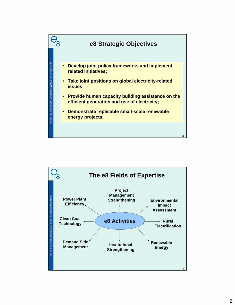
e8 Strategic Objectivese8 Strategic Objectives
• Develop joint policy frameworks and implement related initiatives;
• Take joint positions on global electricity-related issues;
• Provide human capacity building assistance on the efficient generation and use of electricity;
• Demonstrate replicable small-scale renewable energy projects.
4
Th
e e8
: Im
ple
men
tin
g S
ust
ain
able
En
erg
y D
evel
op
men
t W
orl
dw
ide
The e8 Fields of ExpertiseThe e8 Fields of Expertise
Project Management
Strengthening
e8 Activities
Environmental Impact
Assessment
Clean CoalTechnology
RuralElectrification
RenewableEnergy
Institutional Strengthening
Power PlantEfficiency
Demand SideManagement

3
5
Th
e e8
: Im
ple
men
tin
g S
ust
ain
able
En
erg
y D
evel
op
men
t W
orl
dw
ide
e8 Projects and Activities e8 Projects and Activities WorldwideWorldwide
E7-107
E7-82
E7-81
Projects
Capacity Building
Completed
•
Mexico
Nicaragua
Ecuador
Bolivia
Chile
Paraguay
Jordan
Egypt
Tunisia
Lebanon
Syria
Burkina Faso,
Benin, Niger
South Africa
Zimbabwe
Madagascar
Bulgaria
Georgia
Tajikistan
India
Bhutan
Bangladesh
Thailand
Indonesia
Mongolia
China
Laos
Malaysia
Tuvalu
Kenya
Maghreb
Cameroon
Philippines
6
Th
e e8
: Im
ple
men
tin
g S
ust
ain
able
En
erg
y D
evel
op
men
t W
orl
dw
ide
e8 Capital Projectse8 Capital Projects
• Jordan: AIJ project on thermal power plant efficiency improvements [Completed, 2000]
• Indonesia: AIJ project on renewable energy supply systems in Indonesia (solar, wind, hybrid, micro-hydro) [Completed, 2000]
• Benin, Burkina Faso, Niger (W Park): Solar power systems for rural electrification and water supply. [Completed, 2003]
• Bhutan: CDM-registered project supplying hydro-electricity to a remote village in Bhutan. [Completed, 2005]
• Ecuador (Galapagos): Re-powering using renewable energy systems such as wind. [Completed, October 2007]
• Tuvalu (Pacific Islands): Grid-connected solar power installations in Tuvalu. [Completed, February 2008]
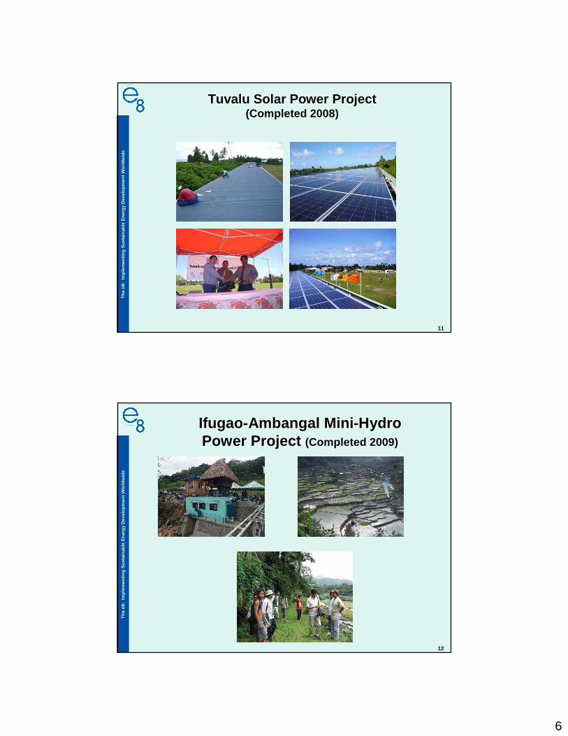
• Ifugao (Philippines): mini hydro project (200 kW) for the preservation of Ifugao's ancient rice terraces [Completed , December 2009]
• Maghreb: Wind for desalination project. [On-going]

4
7
Th
e e8
: Im
ple
men
tin
g S
ust
ain
able
En
erg
y D
evel
op
men
t W
orl
dw
ide
e8 CDM Projectse8 CDM Projects
�The Bhutan Mini Hydro Power Project (70 kW) was the first e8 project to be officially registered as a Clean Development Mechanism (CDM) project under the terms of the Kyoto Protocol. It was also the first project to be registered in the Himalayan Kingdom of Bhutan.
�The San Cristobal, Galapagos, Wind Project (2.4 MW): The project was registered as a CDM project with UNFCCC in May 2008.
8
Th
e e8
: Im
ple
men
tin
g S
ust
ain
able
En
erg
y D
evel
op
men
t W
orl
dw
ide
e8 Human Capacity Building e8 Human Capacity Building ActivitiesActivities
• Seminar on Electricity Interconnection (Ethiopia) [Completed, 2009]
• Solar PV, Design, O&M (Pacific Islands) [Completed, 2008-2009]
• Monitoring Hybrid System & Sustainability (Indonesia)[In implementation]
• Financing Sustainable Electrification Dialogues Workshops 2009-2013 [2 workshops Completed 2009-2010; 6 workshops over the next 3 years]
• DSM workshop (Pacific Islands) [Completed, 2009-2010]
• Grid Connected Solar PV, Design, O&M (Pacific Islands)[In development 2010]
• Industrial Energy Efficiency for emerging economies[In development 2010-2011]
5
9
Th
e e8
: Im
ple
men
tin
g S
ust
ain
able
En
erg
y D
evel
op
men
t W
orl
dw
ide
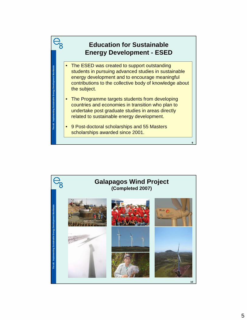
Education for Sustainable Education for Sustainable Energy Development Energy Development -- ESEDESED
• The ESED was created to support outstanding students in pursuing advanced studies in sustainable energy development and to encourage meaningful contributions to the collective body of knowledge about the subject.
• The Programme targets students from developing countries and economies in transition who plan to undertake post graduate studies in areas directly related to sustainable energy development.
• 9 Post-doctoral scholarships and 55 Masters scholarships awarded since 2001.
10
Th
e e8
: Im
ple
men
tin
g S
ust
ain
able
En
erg
y D
evel
op
men
t W
orl
dw
ide
Galapagos Wind ProjectGalapagos Wind Project(Completed 2007)(Completed 2007)
6
11
Th
e e8
: Im
ple
men
tin
g S
ust
ain
able
En
erg
y D
evel
op
men
t W
orl
dw
ide
Tuvalu Solar Power ProjectTuvalu Solar Power Project(Completed 2008)(Completed 2008)
12
Th
e e8
: Im
ple
men
tin
g S
ust
ain
able
En
erg
y D
evel
op
men
t W
orl
dw
ide
IfugaoIfugao--AmbangalAmbangal MiniMini--Hydro Hydro Power Project Power Project ((CompletedCompleted 2009)2009)

7
13
Th
e e8
: Im
ple
men
tin
g S
ust
ain
able
En
erg
y D
evel
op
men
t W
orl
dw
ide
www.e8.orgwww.e8.org

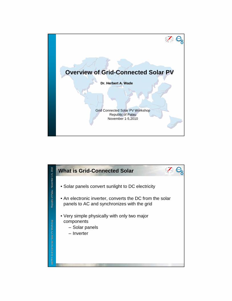
Grid Connected Solar PV WorkshopRepublic of Palau
November 1-5,2010
Overview of Grid-Connected Solar PV
Dr. Herbert A. WadeDr. Herbert A. Wade
e8 /
PP
A D
SM
Wo
rksh
op
F
iji Is
lan
ds
No
vem
ber
2-6
, 200
9e8
/PP
A G
rid
Con
nect
ed S
olar
PV
Wor
ksho
p
R
epub
le8
/PP
A G
rid
Con
nect
ed S
olar
PV
Wor
ksho
p
R
epub
l ic o
f Pal
au
ic o
f Pal
au --
Nov
embe
r 1
Nov
embe
r 1 --
5, 2
010
5, 2
010
What is GridWhat is Grid --Connected SolarConnected Solar
• Solar panels convert sunlight to DC electricity
• An electronic inverter, converts the DC from the solar panels to AC and synchronizes with the grid
• Very simple physically with only two major components
– Solar panels– Inverter

e8 /
PP
A D
SM
Wo
rksh
op
F
iji Is
lan
ds
No
vem
ber
2-6
, 200
9e8
/PP
A G
rid
Con
nect
ed S
olar
PV
Wor
ksho
p
R
epub
le8
/PP
A G
rid
Con
nect
ed S
olar
PV
Wor
ksho
p
R
epub
l ic o
f Pal
au
ic o
f Pal
au --
Nov
embe
r 1
Nov
embe
r 1 --
5, 2
010
5, 2
010
Misconception about Grid Connected PVMisconception about Grid Connected PV
• Grid connected solar does NOT feed its power to the building first then the surplus goes to the grid. All the solar power goes into the grid and all the building power comes from the grid.
– The electricity the building uses from the grid is offset by a credit for the energy fed into the grid from the solar
� This typically is through the use of two meters, one for the energy coming into the building from the grid and one metering the energy going into the grid from the solar
e8 /
PP
A D
SM
Wo
rksh
op
F
iji Is
lan
ds
No
vem
ber
2-6
, 200
9e8
/PP
A G
rid
Con
nect
ed S
olar
PV
Wor
ksho
p
R
epub
le8
/PP
A G
rid
Con
nect
ed S
olar
PV
Wor
ksho
p
R
epub
l ic o
f Pal
au
ic o
f Pal
au --
Nov
embe
r 1
Nov
embe
r 1 --
5, 2
010
5, 2
010
Overall System for GridOverall System for Grid --Connected PVConnected PV
Graphic copyright by Global Sustainable Energy Solutions, Ltd. (GSES)

e8 /
PP
A D
SM
Wo
rksh
op
F
iji Is
lan
ds
No
vem
ber
2-6
, 200
9e8
/PP
A G
rid
Con
nect
ed S
olar
PV
Wor
ksho
p
R
epub
le8
/PP
A G
rid
Con
nect
ed S
olar
PV
Wor
ksho
p
R
epub
l ic o
f Pal
au
ic o
f Pal
au --
Nov
embe
r 1
Nov
embe
r 1 --
5, 2
010
5, 2
010
Concept of Net MeteringConcept of Net Metering
• Net metering is intended to allow solar PV to send energy into the grid at one time and for the user to take out the equivalent energy at another time
– Important for residences since daytime use when the sun is brightest is lowest. Most residential usage is in the evening
– Not so important for buildings with high A/C loads since then the maximum load occurs when the solar is strongest
e8 /
PP
A D
SM
Wo
rksh
op
F
iji Is
lan
ds
No
vem
ber
2-6
, 200
9e8
/PP
A G
rid
Con
nect
ed S
olar
PV
Wor
ksho
p
R
epub
le8
/PP
A G
rid
Con
nect
ed S
olar
PV
Wor
ksho
p
R
epub
l ic o
f Pal
au
ic o
f Pal
au --
Nov
embe
r 1
Nov
embe
r 1 --
5, 2
010
5, 2
010
Net Metering Concept in the PacificNet Metering Concept in the Pacific
• Usually net metering relies on two meters but one meter can be used if it can run backward when power is going into the grid.
– Also special electronic meters that read energy flows both ways can be obtained
• Net metering needs to be arranged to send forward credit for surplus energy delivered to the grid with an annual accounting.
– Solar tends to be seasonal so some months there may be a surplus sent into the grid from solar and some months there will be more used from the grid than sent by the solar

e8 /
PP
A D
SM
Wo
rksh
op
F
iji Is
lan
ds
No
vem
ber
2-6
, 200
9e8
/PP
A G
rid
Con
nect
ed S
olar
PV
Wor
ksho
p
R
epub
le8
/PP
A G
rid
Con
nect
ed S
olar
PV
Wor
ksho
p
R
epub
l ic o
f Pal
au
ic o
f Pal
au --
Nov
embe
r 1
Nov
embe
r 1 --
5, 2
010
5, 2
010
Net Metering Net Metering –– Payment for SurplusPayment for Surplus
• At some time once a year the total energy delivered to the grid from the solar is subtracted from the total energy delivered to the building from the grid. If there is a surplus of energy sent to the grid by the solar over the year, a payment may be made
e8 /
PP
A D
SM
Wo
rksh
op
F
iji Is
lan
ds
No
vem
ber
2-6
, 200
9e8
/PP
A G
rid
Con
nect
ed S
olar
PV
Wor
ksho
p
R
epub
le8
/PP
A G
rid
Con
nect
ed S
olar
PV
Wor
ksho
p
R
epub
l ic o
f Pal
au
ic o
f Pal
au --
Nov
embe
r 1
Nov
embe
r 1 --
5, 2
010
5, 2
010
Payment for Surplus Energy from PVPayment for Surplus Energy from PV
– May be legally required or may be up to the utility� May range from zero up to more than the per
kWh retail charge.� If zero encourages users to keep the scale of
PV small enough so there is never an annual surplus
� If greater than retail power rates, encourages large installations to make money
� Real cost saving to the utility is in fuel as adjusted for the cost of maintaining spinning reserves and for grid maintenance
» Major cost savings for PIC utilities since the great majority of per kWh cost is fuel
e8 /
PP
A D
SM
Wo
rksh
op
F
iji Is
lan
ds
No
vem
ber
2-6
, 200
9e8
/PP
A G
rid
Con
nect
ed S
olar
PV
Wor
ksho
p
R
epub
le8
/PP
A G
rid
Con
nect
ed S
olar
PV
Wor
ksho
p
R
epub
l ic o
f Pal
au
ic o
f Pal
au --
Nov
embe
r 1
Nov
embe
r 1 --
5, 2
010
5, 2
010
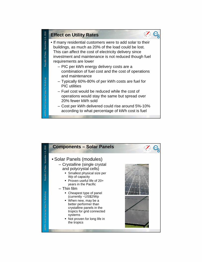
Effect on Utility RatesEffect on Utility Rates
• If many residential customers were to add solar to their buildings, as much as 20% of the load could be lost. This can affect the cost of electricity delivery since investment and maintenance is not reduced though fuel requirements are lower
– PIC per kWh energy delivery costs are a combination of fuel cost and the cost of operations and maintenance
– Typically 60%-80% of per kWh costs are fuel for PIC utilities
– Fuel cost would be reduced while the cost of operations would stay the same but spread over 20% fewer kWh sold
– Cost per kWh delivered could rise around 5%-10% according to what percentage of kWh cost is fuel
e8 /
PP
A D
SM
Wo
rksh
op
F
iji Is
lan
ds
No
vem
ber
2-6
, 200
9e8
/PP
A G
rid
Con
nect
ed S
olar
PV
Wor
ksho
p
R
epub
le8
/PP
A G
rid
Con
nect
ed S
olar
PV
Wor
ksho
p
R
epub
l ic o
f Pal
au
ic o
f Pal
au --
Nov
embe
r 1
Nov
embe
r 1 --
5, 2
010
5, 2
010 Components Components –– Solar PanelsSolar Panels
• Solar Panels (modules)– Crystalline (single crystal
and polycrystal cells)� Smallest physical size per
Wp of capacity� Proven useful life of 20+
years in the Pacific– Thin film
� Cheapest type of panel (currently ~US$2/Wp
� When new, may be a better performer than crystalline panels in the tropics for grid connected systems
� Not proven for long life in the tropics

e8 /
PP
A D
SM
Wo
rksh
op
F
iji Is
lan
ds
No
vem
ber
2-6
, 200
9e8
/PP
A G
rid
Con
nect
ed S
olar
PV
Wor
ksho
p
R
epub
le8
/PP
A G
rid
Con
nect
ed S
olar
PV
Wor
ksho
p
R
epub
l ic o
f Pal
au
ic o
f Pal
au --
Nov
embe
r 1
Nov
embe
r 1 --
5, 2
010
5, 2
010
• Panel interconnections– Panels connected in series “strings” to provide
proper voltage for inverter input– Connections may be through the use of “quick
connect” push-in connectors or screw-type junction boxes� Due to prior bad experiences there are
concerns about the long term quality of quick-connect (MC-4) cable connections in the highly corrosive and high temperature island environment
Panel Connections for Grid-Connected Solar
e8 /
PP
A D
SM
Wo
rksh
op
F
iji Is
lan
ds
No
vem
ber
2-6
, 200
9e8
/PP
A G
rid
Con
nect
ed S
olar
PV
Wor
ksho
p
R
epub
le8
/PP
A G
rid
Con
nect
ed S
olar
PV
Wor
ksho
p
R
epub
l ic o
f Pal
au
ic o
f Pal
au --
Nov
embe
r 1
Nov
embe
r 1 --
5, 2
010
5, 2
010
Connector Pair (- & +)
Individual connectors
Melting of connector in service in Fiji caused by resistance heating due to salt corrosion
e8 /
PP
A D
SM
Wo
rksh
op
F
iji Is
lan
ds
No
vem
ber
2-6
, 200
9e8
/PP
A G
rid
Con
nect
ed S
olar
PV
Wor
ksho
p
R
epub
le8
/PP
A G
rid
Con
nect
ed S
olar
PV
Wor
ksho
p
R
epub
l ic o
f Pal
au
ic o
f Pal
au --
Nov
embe
r 1
Nov
embe
r 1 --
5, 2
010
5, 2
010
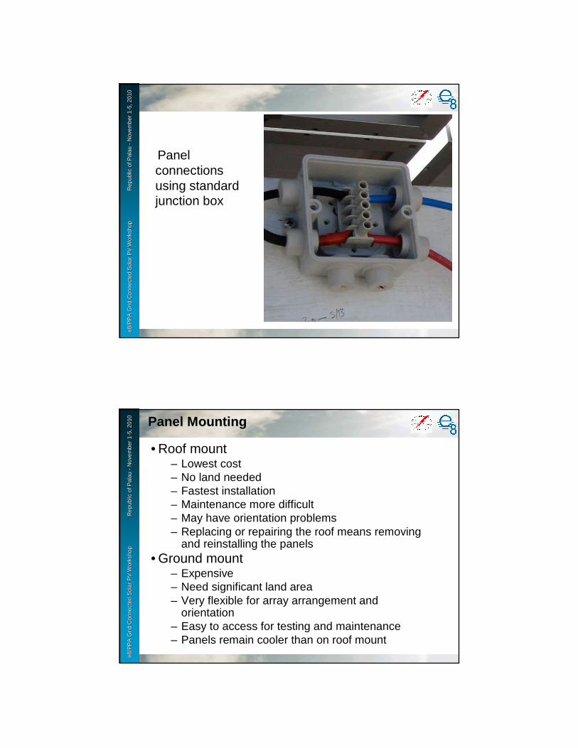
Panel connections using standard junction box
e8 /
PP
A D
SM
Wo
rksh
op
F
iji Is
lan
ds
No
vem
ber
2-6
, 200
9e8
/PP
A G
rid
Con
nect
ed S
olar
PV
Wor
ksho
p
R
epub
le8
/PP
A G
rid
Con
nect
ed S
olar
PV
Wor
ksho
p
R
epub
l ic o
f Pal
au
ic o
f Pal
au --
Nov
embe
r 1
Nov
embe
r 1 --
5, 2
010
5, 2
010
Panel MountingPanel Mounting
• Roof mount– Lowest cost– No land needed– Fastest installation– Maintenance more difficult– May have orientation problems– Replacing or repairing the roof means removing
and reinstalling the panels• Ground mount
– Expensive– Need significant land area– Very flexible for array arrangement and
orientation– Easy to access for testing and maintenance– Panels remain cooler than on roof mount

e8 /
PP
A D
SM
Wo
rksh
op
F
iji Is
lan
ds
No
vem
ber
2-6
, 200
9e8
/PP
A G
rid
Con
nect
ed S
olar
PV
Wor
ksho
p
R
epub
le8
/PP
A G
rid
Con
nect
ed S
olar
PV
Wor
ksho
p
R
epub
l ic o
f Pal
au
ic o
f Pal
au --
Nov
embe
r 1
Nov
embe
r 1 --
5, 2
010
5, 2
010
Niue School ~20 kWp (top roof mount) and Hospital ~31 kWp (bottom ground mount)
e8 /
PP
A D
SM
Wo
rksh
op
F
iji Is
lan
ds
No
vem
ber
2-6
, 200
9e8
/PP
A G
rid
Con
nect
ed S
olar
PV
Wor
ksho
p
R
epub
le8
/PP
A G
rid
Con
nect
ed S
olar
PV
Wor
ksho
p
R
epub
l ic o
f Pal
au
ic o
f Pal
au --
Nov
embe
r 1
Nov
embe
r 1 --
5, 2
010
5, 2
010
Mounting on Flat Roof (Mounting on Flat Roof ( ChuukChuuk ))

e8 /
PP
A D
SM
Wo
rksh
op
F
iji Is
lan
ds
No
vem
ber
2-6
, 200
9e8
/PP
A G
rid
Con
nect
ed S
olar
PV
Wor
ksho
p
R
epub
le8
/PP
A G
rid
Con
nect
ed S
olar
PV
Wor
ksho
p
R
epub
l ic o
f Pal
au
ic o
f Pal
au --
Nov
embe
r 1
Nov
embe
r 1 --
5, 2
010
5, 2
010
Panel orientationPanel orientation
• In most places, for the most kWh per year, tilt at about the latitude angle toward the equator.
– Provides output that peaks fairly sharply between 11 and 12 noon. ~US$0.45 per kWh
– Some places (such as Palau) have seasonal solar energy patterns that make the optimum tilt not equal to the latitude angle
e8 /
PP
A D
SM
Wo
rksh
op
F
iji Is
lan
ds
No
vem
ber
2-6
, 200
9e8
/PP
A G
rid
Con
nect
ed S
olar
PV
Wor
ksho
p
R
epub
le8
/PP
A G
rid
Con
nect
ed S
olar
PV
Wor
ksho
p
R
epub
l ic o
f Pal
au
ic o
f Pal
au --
Nov
embe
r 1
Nov
embe
r 1 --
5, 2
010
5, 2
010
WiringWiring
• Wire must be large enough to pass peak currents without significant voltage drop
– Maximum energy loss of 2% is ok• Insulation must be able to withstand high
temperatures, high levels of weather exposure and high levels of sunlight (UV) exposure as well as the voltage of the string.
– Typically double insulated cable with the external insulation highly resistant to UV and high temperatures
e8 /
PP
A D
SM
Wo
rksh
op
F
iji Is
lan
ds
No
vem
ber
2-6
, 200
9e8
/PP
A G
rid
Con
nect
ed S
olar
PV
Wor
ksho
p
R
epub
le8
/PP
A G
rid
Con
nect
ed S
olar
PV
Wor
ksho
p
R
epub
l ic o
f Pal
au
ic o
f Pal
au --
Nov
embe
r 1
Nov
embe
r 1 --
5, 2
010
5, 2
010
• Converts DC from panels to grid quality AC• Automatically disconnects if grid fails
– Typically senses and disconnects due to� Frequency variations� Voltage variations� Excessive rate of frequency variation� Excessive rate of voltage variation� Other parameters such as over temperature,
over current, etc.
• Reconnects automatically after sensing at least five minutes of normal grid operation and there are normal conditions in the inverter itself
Inverter
e8 /
PP
A D
SM
Wo
rksh
op
F
iji Is
lan
ds
No
vem
ber
2-6
, 200
9e8
/PP
A G
rid
Con
nect
ed S
olar
PV
Wor
ksho
p
R
epub
le8
/PP
A G
rid
Con
nect
ed S
olar
PV
Wor
ksho
p
R
epub
l ic o
f Pal
au
ic o
f Pal
au --
Nov
embe
r 1
Nov
embe
r 1 --
5, 2
010
5, 2
010
– Allowable input DC voltage varies with some models allowing less than 200V and others to over 1000V
– Output voltage and frequency programmable– Most inverters can be easily paralleled or used in
multi-phase configurations– Often installed with many paralleled inverter units
in a rack or on a wall for larger systems– May include an isolation transformer or be direct
connected
Inverter Characteristics

e8 /
PP
A D
SM
Wo
rksh
op
F
iji Is
lan
ds
No
vem
ber
2-6
, 200
9e8
/PP
A G
rid
Con
nect
ed S
olar
PV
Wor
ksho
p
R
epub
le8
/PP
A G
rid
Con
nect
ed S
olar
PV
Wor
ksho
p
R
epub
l ic o
f Pal
au
ic o
f Pal
au --
Nov
embe
r 1
Nov
embe
r 1 --
5, 2
010
5, 2
010
Inside one residential sized inverter (1.7 kW). Note the emergency DC disconnect handle at the bottom left and AC connection bottom right
Small Inverters
e8 /
PP
A D
SM
Wo
rksh
op
F
iji Is
lan
ds
No
vem
ber
2-6
, 200
9e8
/PP
A G
rid
Con
nect
ed S
olar
PV
Wor
ksho
p
R
epub
le8
/PP
A G
rid
Con
nect
ed S
olar
PV
Wor
ksho
p
R
epub
l ic o
f Pal
au
ic o
f Pal
au --
Nov
embe
r 1
Nov
embe
r 1 --
5, 2
010
5, 2
010
Large Scale Inverter (over ~50 kW)Large Scale Inverter (over ~50 kW)
• Rack of paralleled inverters for larger scale PV Grid Connection
Fronius commercial inverter unit

e8 /
PP
A D
SM
Wo
rksh
op
F
iji Is
lan
ds
No
vem
ber
2-6
, 200
9e8
/PP
A G
rid
Con
nect
ed S
olar
PV
Wor
ksho
p
R
epub
le8
/PP
A G
rid
Con
nect
ed S
olar
PV
Wor
ksho
p
R
epub
l ic o
f Pal
au
ic o
f Pal
au --
Nov
embe
r 1
Nov
embe
r 1 --
5, 2
010
5, 2
010
Bank of 100 kW invertersBank of 100 kW inverters
Photo by SMA
e8 /
PP
A D
SM
Wo
rksh
op
F
iji Is
lan
ds
No
vem
ber
2-6
, 200
9e8
/PP
A G
rid
Con
nect
ed S
olar
PV
Wor
ksho
p
R
epub
le8
/PP
A G
rid
Con
nect
ed S
olar
PV
Wor
ksho
p
R
epub
l ic o
f Pal
au
ic o
f Pal
au --
Nov
embe
r 1
Nov
embe
r 1 --
5, 2
010
5, 2
010
Wall of 1.7 kW inverters (6 in parallel for each phase) during wiring at the Niue hospital.
3 Phase Multiple Inverter Installation

e8 /
PP
A D
SM
Wo
rksh
op
F
iji Is
lan
ds
No
vem
ber
2-6
, 200
9e8
/PP
A G
rid
Con
nect
ed S
olar
PV
Wor
ksho
p
R
epub
le8
/PP
A G
rid
Con
nect
ed S
olar
PV
Wor
ksho
p
R
epub
l ic o
f Pal
au
ic o
f Pal
au --
Nov
embe
r 1
Nov
embe
r 1 --
5, 2
010
5, 2
010
• Inverters should be sealed with no active components exposed to the air, only heat exchangers and the transformer.
– Absolutely avoid inverters with a cooling fan that blows ambient air onto the circuit board if it is to be installed where corrosion is a problem – most Pacific Islands.
Inverters for the Pacific Islands
e8 /
PP
A D
SM
Wo
rksh
op
F
iji Is
lan
ds
No
vem
ber
2-6
, 200
9e8
/PP
A G
rid
Con
nect
ed S
olar
PV
Wor
ksho
p
R
epub
le8
/PP
A G
rid
Con
nect
ed S
olar
PV
Wor
ksho
p
R
epub
l ic o
f Pal
au
ic o
f Pal
au --
Nov
embe
r 1
Nov
embe
r 1 --
5, 2
010
5, 2
010
DC Disconnects, Lightning, and EarthingDC Disconnects, Lightning, and Earthing
• Electrical codes for Australia, New Zealand and the US all require each string to have its own DC disconnect switch
• Lighting protection is optional but often installed
– Lighting surge suppressors do wear out so must be monitored
– Single earthing point for all components is required

e8 /
PP
A D
SM
Wo
rksh
op
F
iji Is
lan
ds
No
vem
ber
2-6
, 200
9e8
/PP
A G
rid
Con
nect
ed S
olar
PV
Wor
ksho
p
R
epub
le8
/PP
A G
rid
Con
nect
ed S
olar
PV
Wor
ksho
p
R
epub
l ic o
f Pal
au
ic o
f Pal
au --
Nov
embe
r 1
Nov
embe
r 1 --
5, 2
010
5, 2
010
Lightning surge suppressors and DC disconnect switches for each string
e8 /
PP
A D
SM
Wo
rksh
op
F
iji Is
lan
ds
No
vem
ber
2-6
, 200
9e8
/PP
A G
rid
Con
nect
ed S
olar
PV
Wor
ksho
p
R
epub
le8
/PP
A G
rid
Con
nect
ed S
olar
PV
Wor
ksho
p
R
epub
l ic o
f Pal
au
ic o
f Pal
au --
Nov
embe
r 1
Nov
embe
r 1 --
5, 2
010
5, 2
010
• Typical circuit for one inverter module
– Multiple strings per inverter
– Note two meters, one for the solar and one for the use by the client
• More inverter strings equals more power
System Circuit

e8 /
PP
A D
SM
Wo
rksh
op
F
iji Is
lan
ds
No
vem
ber
2-6
, 200
9e8
/PP
A G
rid
Con
nect
ed S
olar
PV
Wor
ksho
p
R
epub
le8
/PP
A G
rid
Con
nect
ed S
olar
PV
Wor
ksho
p
R
epub
l ic o
f Pal
au
ic o
f Pal
au --
Nov
embe
r 1
Nov
embe
r 1 --
5, 2
010
5, 2
010
Niue Hospital SystemNiue Hospital System
• 18 inverters (3 phase system)• 36 strings of five 170 Wp panels each (total 1.7kW per
inverter, 30.6kWp of panels)• Ground mounting designed to resist category 5 cyclone• 200V nominal DC feed voltage• 3 phase feed-in at Hospital transformer
e8 /
PP
A D
SM
Wo
rksh
op
F
iji Is
lan
ds
No
vem
ber
2-6
, 200
9e8
/PP
A G
rid
Con
nect
ed S
olar
PV
Wor
ksho
p
R
epub
le8
/PP
A G
rid
Con
nect
ed S
olar
PV
Wor
ksho
p
R
epub
l ic o
f Pal
au
ic o
f Pal
au --
Nov
embe
r 1
Nov
embe
r 1 --
5, 2
010
5, 2
010
MaintenanceMaintenance
• Panels require very low maintenance and have a long life (20+ years). Most problems are with the packaging.
– Clean when necessary (usually only if some object blows onto the panels, dirt and dust usually is not a problem)� Should be cleaned at commissioning because
manufacturing residue may remain on glass– String voltage and current should be checked for
consistency between strings at least weekly through the data link to the inverter� if one string is consistently low relative to the
others, probably a connection or wiring problem exists

e8 /
PP
A D
SM
Wo
rksh
op
F
iji Is
lan
ds
No
vem
ber
2-6
, 200
9e8
/PP
A G
rid
Con
nect
ed S
olar
PV
Wor
ksho
p
R
epub
le8
/PP
A G
rid
Con
nect
ed S
olar
PV
Wor
ksho
p
R
epub
l ic o
f Pal
au
ic o
f Pal
au --
Nov
embe
r 1
Nov
embe
r 1 --
5, 2
010
5, 2
010
Corrosion due to water entry
Discoloration of material used for cell encapsulation
Delamination of cells from the glass cover
e8 /
PP
A D
SM
Wo
rksh
op
F
iji Is
lan
ds
No
vem
ber
2-6
, 200
9e8
/PP
A G
rid
Con
nect
ed S
olar
PV
Wor
ksho
p
R
epub
le8
/PP
A G
rid
Con
nect
ed S
olar
PV
Wor
ksho
p
R
epub
l ic o
f Pal
au
ic o
f Pal
au --
Nov
embe
r 1
Nov
embe
r 1 --
5, 2
010
5, 2
010
• Inverter failures follow the “bathtub” curve: Most failures occur early (within 2 years) then maybe 10 years pass with very low failure rates then the failure rate starts to rise rapidly.
• Prepare for 15% failures during the first couple of years by having spares in stock.
• Monitor inverter outputs for consistency among inverters at least weekly and preferably every afternoon
• Most inverter problems can only be fixed by replacement of the inverter with a spare. Local repair of most problems is impossible.
Inverter Failures
e8 /
PP
A D
SM
Wo
rksh
op
F
iji Is
lan
ds
No
vem
ber
2-6
, 200
9e8
/PP
A G
rid
Con
nect
ed S
olar
PV
Wor
ksho
p
R
epub
le8
/PP
A G
rid
Con
nect
ed S
olar
PV
Wor
ksho
p
R
epub
l ic o
f Pal
au
ic o
f Pal
au --
Nov
embe
r 1
Nov
embe
r 1 --
5, 2
010
5, 2
010
The key to operational maintenance is the use of the data presentation capability of the inverters and associated data loggers for use with a computer (e.g. SMA’s ‘Webbox’). Every inverter and every string is constantly monitored and data made available to a laptop or networked computer for checks of operation and for initial troubleshooting.
The output of any string or inverter that is seen to be significantly different from the others is a sign of a problem to be checked.
Operational Maintenance
e8 /
PP
A D
SM
Wo
rksh
op
F
iji Is
lan
ds
No
vem
ber
2-6
, 200
9e8
/PP
A G
rid
Con
nect
ed S
olar
PV
Wor
ksho
p
R
epub
le8
/PP
A G
rid
Con
nect
ed S
olar
PV
Wor
ksho
p
R
epub
l ic o
f Pal
au
ic o
f Pal
au --
Nov
embe
r 1
Nov
embe
r 1 --
5, 2
010
5, 2
010
Other MaintenanceOther Maintenance
• Check the status of lightning arresters monthly (indicator color)
• Clean heat exchanger surfaces and check fan operation on inverters at least monthly
• Examine panels at least annually for corrosion, delamination or discoloration and problems with mountings

e8 /
PP
A D
SM
Wo
rksh
op
F
iji Is
lan
ds
No
vem
ber
2-6
, 200
9e8
/PP
A G
rid
Con
nect
ed S
olar
PV
Wor
ksho
p
R
epub
le8
/PP
A G
rid
Con
nect
ed S
olar
PV
Wor
ksho
p
R
epub
l ic o
f Pal
au
ic o
f Pal
au --
Nov
embe
r 1
Nov
embe
r 1 --
5, 2
010
5, 2
010
WarrantiesWarranties
• Panels (read the fine print!!!)– Physical problems 5 to 10 year warranty with
panel replacement– Output warranty 20-25 years. Obligation is only to
provide replacement of lost capacity� Generally useless, mainly for PR purposes
• Inverter– Typically 5 years with 10 years or more usually
available at extra cost– Usually does not pay for shipping which can be
expensive
Grid Connected Solar PV WorkshopRepublic of Palau
November 1-5,2010
Panels for Grid-Connected Solar PV
Dr. Herbert A. WadeDr. Herbert A. Wade
e8 /
PP
A D
SM
Wo
rksh
op
F
iji Is
lan
ds
No
vem
ber
2-6
, 200
9e8
/PP
A G
rid
Con
nect
ed S
olar
PV
Wor
ksho
p
R
epub
le8
/PP
A G
rid
Con
nect
ed S
olar
PV
Wor
ksho
p
R
epub
l ic o
f Pal
au
ic o
f Pal
au --
Nov
embe
r 1
Nov
embe
r 1 --
5, 2
010
5, 2
010
Solar PanelsSolar Panels

e8 /
PP
A D
SM
Wo
rksh
op
F
iji Is
lan
ds
No
vem
ber
2-6
, 200
9e8
/PP
A G
rid
Con
nect
ed S
olar
PV
Wor
ksho
p
R
epub
le8
/PP
A G
rid
Con
nect
ed S
olar
PV
Wor
ksho
p
R
epub
l ic o
f Pal
au
ic o
f Pal
au --
Nov
embe
r 1
Nov
embe
r 1 --
5, 2
010
5, 2
010 PhotovoltaicsPhotovoltaics
• The term photovoltaics (PV) refers to the conversion of light energy (in this case light from the sun) to DC electricity.
• The technology used today dates from the 1950s and became commercial in the 60’s when power for space craft was provided by solar photovoltaics
• Today PV generation is by combinations of solar panels with size rated by the maximum Watts of electricity they can produce under a set of standard conditions
e8 /
PP
A D
SM
Wo
rksh
op
F
iji Is
lan
ds
No
vem
ber
2-6
, 200
9e8
/PP
A G
rid
Con
nect
ed S
olar
PV
Wor
ksho
p
R
epub
le8
/PP
A G
rid
Con
nect
ed S
olar
PV
Wor
ksho
p
R
epub
l ic o
f Pal
au
ic o
f Pal
au --
Nov
embe
r 1
Nov
embe
r 1 --
5, 2
010
5, 2
010
Solar Panel Power RatingSolar Panel Power Rating• Panels are rated in Watts Peak (Wp).
• This is the maximum number of Watts power that the panel should produce if:
– it is exposed to 1000 W/m2 of sunlight– The sunlight is coming straight onto the panel– The panel is clean– There is a cell temperature of 25°C– The sunlight passes through an air mass of 1.5
(about a 45° angle above the horizon)– Power from the panel is delivered to the load at the
maximum power point of the panel (the optimum loading)

e8 /
PP
A D
SM
Wo
rksh
op
F
iji Is
lan
ds
No
vem
ber
2-6
, 200
9e8
/PP
A G
rid
Con
nect
ed S
olar
PV
Wor
ksho
p
R
epub
le8
/PP
A G
rid
Con
nect
ed S
olar
PV
Wor
ksho
p
R
epub
l ic o
f Pal
au
ic o
f Pal
au --
Nov
embe
r 1
Nov
embe
r 1 --
5, 2
010
5, 2
010
Actual Panel OutputActual Panel Output
• Solar energy is almost never is great enough to provide 1000 W/m2 of solar radiation. Typically 800-900 W/m2 is the highest seen on clear days at noon.
• In the tropics, solar cells are 50C to over 60C. Higher cell temperatures result in lowered output of 10% to 15% over rated values
• Panels rarely face directly toward the sun, surface reflections increase and output decreases as a result
• There is often a mismatch between the load and the panel resulting in a few percent reduction from the rated value.
e8 /
PP
A D
SM
Wo
rksh
op
F
iji Is
lan
ds
No
vem
ber
2-6
, 200
9e8
/PP
A G
rid
Con
nect
ed S
olar
PV
Wor
ksho
p
R
epub
le8
/PP
A G
rid
Con
nect
ed S
olar
PV
Wor
ksho
p
R
epub
l ic o
f Pal
au
ic o
f Pal
au --
Nov
embe
r 1
Nov
embe
r 1 --
5, 2
010
5, 2
010
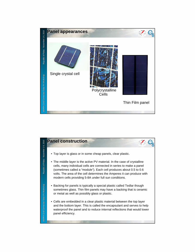
Panel TypesPanel Types
• Single Crystal construction. Each cell is a single crystal of silicon. This is the oldest design and provides the highest light to electricity conversion efficiency. Round cells are made initially but they may be cut square. Panel made up of many cells connected in series. Very reliable.
• Polycrystalline construction. Each cell includes several large crystals of silicon. Cells can be any shape. Almost as high efficiency as single cells. Panel made up of many cells connected in series. Excellent reliability.
• Thin film construction. Silicon or other PV material is put in a very thin layer onto metal or plastic. Mass production is relatively easy and theoretically can be cheaper than crystal based panels. Efficiency low to medium. Reliability varies from poor to good. Sometimes called “amorphous” panels.
e8 /
PP
A D
SM
Wo
rksh
op
F
iji Is
lan
ds
No
vem
ber
2-6
, 200
9e8
/PP
A G
rid
Con
nect
ed S
olar
PV
Wor
ksho
p
R
epub
le8
/PP
A G
rid
Con
nect
ed S
olar
PV
Wor
ksho
p
R
epub
l ic o
f Pal
au
ic o
f Pal
au --
Nov
embe
r 1
Nov
embe
r 1 --
5, 2
010
5, 2
010 Panel appearancesPanel appearances
Single crystal cell
PolycrystallineCells
Thin Film panel
e8 /
PP
A D
SM
Wo
rksh
op
F
iji Is
lan
ds
No
vem
ber
2-6
, 200
9e8
/PP
A G
rid
Con
nect
ed S
olar
PV
Wor
ksho
p
R
epub
le8
/PP
A G
rid
Con
nect
ed S
olar
PV
Wor
ksho
p
R
epub
l ic o
f Pal
au
ic o
f Pal
au --
Nov
embe
r 1
Nov
embe
r 1 --
5, 2
010
5, 2
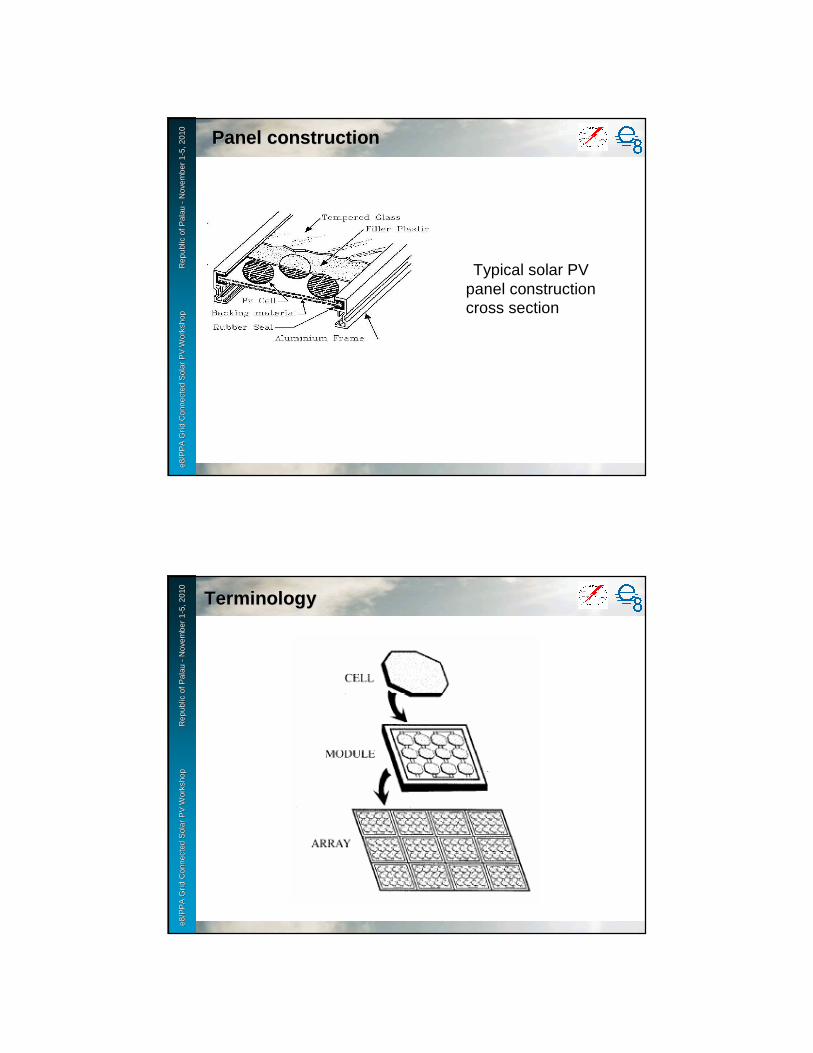
010 Panel constructionPanel construction
• Top layer is glass or in some cheap panels, clear plastic.
• The middle layer is the active PV material. In the case of crystalline cells, many individual cells are connected in series to make a panel (sometimes called a “module”). Each cell produces about 0.5 to 0.6 volts. The area of the cell determines the Amperes it can produce with modern cells providing 5-8A under full sun conditions.
• Backing for panels is typically a special plastic called Tedlar though sometimes glass. Thin film panels may have a backing that is ceramic or metal as well as possibly glass or plastic.
• Cells are embedded in a clear plastic material between the top layer and the bottom layer. This is called the encapsulant and serves to help waterproof the panel and to reduce internal reflections that would lower panel efficiency.
e8 /
PP
A D
SM
Wo
rksh
op
F
iji Is
lan
ds
No
vem
ber
2-6
, 200
9e8
/PP
A G
rid
Con
nect
ed S
olar
PV
Wor
ksho
p
R
epub
le8
/PP
A G
rid
Con
nect
ed S
olar
PV
Wor
ksho
p
R
epub
l ic o
f Pal
au
ic o
f Pal
au --
Nov
embe
r 1
Nov
embe
r 1 --
5, 2
010
5, 2
010
Panel constructionPanel construction
Typical solar PV panel construction cross section
e8 /
PP
A D
SM
Wo
rksh
op
F
iji Is
lan
ds
No
vem
ber
2-6
, 200
9e8
/PP
A G
rid
Con
nect
ed S
olar
PV
Wor
ksho
p
R
epub
le8
/PP
A G
rid
Con
nect
ed S
olar
PV
Wor
ksho
p
R
epub
l ic o
f Pal
au
ic o
f Pal
au --
Nov
embe
r 1
Nov
embe
r 1 --
5, 2
010
5, 2
010
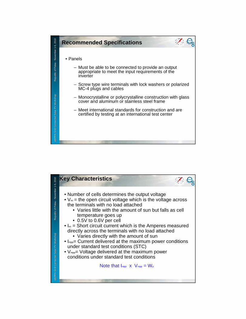
TerminologyTerminology
e8 /
PP
A D
SM
Wo
rksh
op
F
iji Is
lan
ds
No
vem
ber
2-6
, 200
9e8
/PP
A G
rid
Con
nect
ed S
olar
PV
Wor
ksho
p
R
epub
le8
/PP
A G
rid
Con
nect
ed S
olar
PV
Wor
ksho
p
R
epub
l ic o
f Pal
au
ic o
f Pal
au --
Nov
embe
r 1
Nov
embe
r 1 --
5, 2
010
5, 2
010
Recommended SpecificationsRecommended Specifications
• Panels
– Must be able to be connected to provide an output appropriate to meet the input requirements of the inverter
– Screw type wire terminals with lock washers or polarized MC-4 plugs and cables
– Monocrystalline or polycrystalline construction with glass cover and aluminum or stainless steel frame
– Meet international standards for construction and are certified by testing at an international test center
e8 /
PP
A D
SM
Wo
rksh
op
F
iji Is
lan
ds
No
vem
ber
2-6
, 200
9e8
/PP
A G
rid
Con
nect
ed S
olar
PV
Wor
ksho
p
R
epub
le8
/PP
A G
rid
Con
nect
ed S
olar
PV
Wor
ksho
p
R
epub
l ic o
f Pal
au
ic o
f Pal
au --
Nov
embe
r 1
Nov
embe
r 1 --
5, 2
010
5, 2
010 Key CharacteristicsKey Characteristics
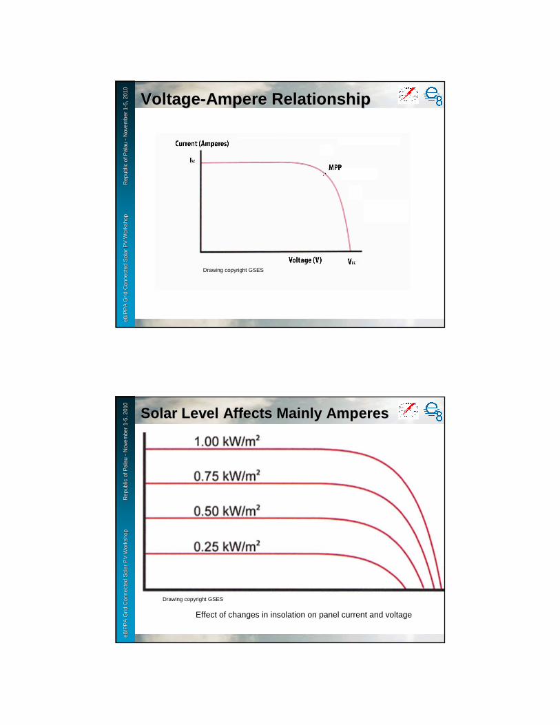
• Number of cells determines the output voltage• Voc = the open circuit voltage which is the voltage across
the terminals with no load attached• Varies little with the amount of sun but falls as cell
temperature goes up• 0.5V to 0.6V per cell
• Isc = Short circuit current which is the Amperes measured directly across the terminals with no load attached
• Varies directly with the amount of sun• Impp= Current delivered at the maximum power conditions
under standard test conditions (STC)• Vmpp= Voltage delivered at the maximum power
conditions under standard test conditions
Note that Impp x Vmpp = Wp
e8 /
PP
A D
SM
Wo
rksh
op
F
iji Is
lan
ds
No
vem
ber
2-6
, 200
9e8
/PP
A G
rid
Con
nect
ed S
olar
PV
Wor
ksho
p
R
epub
le8
/PP
A G
rid
Con
nect
ed S
olar
PV
Wor
ksho
p
R
epub
l ic o
f Pal
au
ic o
f Pal
au --
Nov
embe
r 1
Nov
embe
r 1 --
5, 2
010
5, 2
010
VoltageVoltage --Ampere RelationshipAmpere Relationship
Drawing copyright GSES
e8 /
PP
A D
SM
Wo
rksh
op
F
iji Is
lan
ds
No
vem
ber
2-6
, 200
9e8
/PP
A G
rid
Con
nect
ed S
olar
PV
Wor
ksho
p
R
epub
le8
/PP
A G
rid
Con
nect
ed S
olar
PV
Wor
ksho
p
R
epub
l ic o
f Pal
au
ic o
f Pal
au --
Nov
embe
r 1
Nov
embe
r 1 --
5, 2
010
5, 2
010
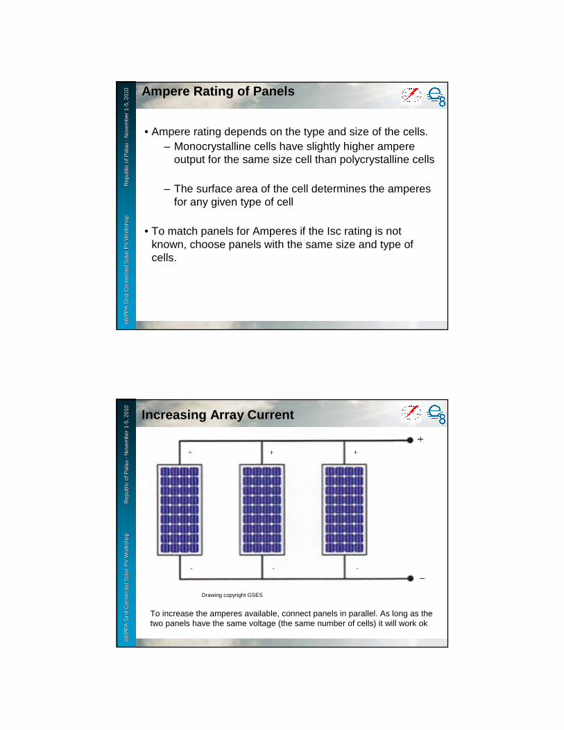
SolarSolar Level Affects Mainly AmperesLevel Affects Mainly Amperes
Effect of changes in insolation on panel current and voltage
Drawing copyright GSES

e8 /
PP
A D
SM
Wo
rksh
op
F
iji Is
lan
ds
No
vem
ber
2-6
, 200
9e8
/PP
A G
rid
Con
nect
ed S
olar
PV
Wor
ksho
p
R
epub
le8
/PP
A G
rid
Con
nect
ed S
olar
PV
Wor
ksho
p
R
epub
l ic o
f Pal
au
ic o
f Pal
au --
Nov
embe
r 1
Nov
embe
r 1 --
5, 2
010
5, 2
010 Connecting PanelsConnecting Panels
• Connecting panels in series (+ terminal of one panel connected to – terminal of the next) results in adding the voltage of the series connected panels
• Easy with plug and cable type connections. The positive connector and the negative connector mate
• Connecting panels in parallel (+ terminal of one panel connected to + terminal of the other and – terminal of one panel connected to – terminal of the other) results in adding the amperes produced by each panel.
• Requires a junction box since cable plugs/sockets do not mate
e8 /
PP
A D
SM
Wo
rksh
op
F
iji Is
lan
ds
No
vem
ber
2-6
, 200
9e8
/PP
A G
rid
Con
nect
ed S
olar
PV
Wor
ksho
p
R
epub
le8
/PP
A G
rid
Con
nect
ed S
olar
PV
Wor
ksho
p
R
epub
l ic o
f Pal
au
ic o
f Pal
au --
Nov
embe
r 1
Nov
embe
r 1 --
5, 2
010
5, 2
010
Increasing Array VoltageIncreasing Array Voltage
Panels can be connected in series to increase output voltage. A series connection will work well only if the panels have the same ampere rating.
Drawing copyright GSES
e8 /
PP
A D
SM
Wo
rksh
op
F
iji Is
lan
ds
No
vem
ber
2-6
, 200
9e8
/PP
A G
rid
Con
nect
ed S
olar
PV
Wor
ksho
p
R
epub
le8
/PP
A G
rid
Con
nect
ed S
olar
PV
Wor
ksho
p
R
epub
l ic o
f Pal
au
ic o
f Pal
au --
Nov
embe
r 1
Nov
embe
r 1 --
5, 2
010
5, 2
010 Ampere Rating of PanelsAmpere Rating of Panels
• Ampere rating depends on the type and size of the cells.– Monocrystalline cells have slightly higher ampere
output for the same size cell than polycrystalline cells
– The surface area of the cell determines the amperes for any given type of cell
• To match panels for Amperes if the Isc rating is not known, choose panels with the same size and type of cells.
e8 /
PP
A D
SM
Wo
rksh
op
F
iji Is
lan
ds
No
vem
ber
2-6
, 200
9e8
/PP
A G
rid
Con
nect
ed S
olar
PV
Wor
ksho
p
R
epub
le8
/PP
A G
rid
Con
nect
ed S
olar
PV
Wor
ksho
p
R
epub
l ic o
f Pal
au
ic o
f Pal
au --
Nov
embe
r 1
Nov
embe
r 1 --
5, 2
010
5, 2
010
Increasing Array CurrentIncreasing Array Current
To increase the amperes available, connect panels in parallel. As long as the two panels have the same voltage (the same number of cells) it will work ok
Drawing copyright GSES

e8 /
PP
A D
SM
Wo
rksh
op
F
iji Is
lan
ds
No
vem
ber
2-6
, 200
9e8
/PP
A G
rid
Con
nect
ed S
olar
PV
Wor
ksho
p
R
epub
le8
/PP
A G
rid
Con
nect
ed S
olar
PV
Wor
ksho
p
R
epub
l ic o
f Pal
au
ic o
f Pal
au --
Nov
embe
r 1
Nov
embe
r 1 --
5, 2
010
5, 2
010
Voltage Rating of PanelsVoltage Rating of Panels
• Output voltage is determined by the number of cells connected in series on the panel and cell temperature.
– To match voltages for panels, the two panels should have the same number of cells.� It does not matter whether they are
monocrystalline or polycrystalline, both have the same voltage of about 0.5V-0.6V per cell
• Also rated according to the maximum voltage allowed between the cells and the frame
– Typically 600V though some panels can handle over 1000 V
e8 /
PP
A D
SM
Wo
rksh
op
F
iji Is
lan
ds
No
vem
ber
2-6
, 200
9e8
/PP
A G
rid
Con
nect
ed S
olar
PV
Wor
ksho
p
R
epub
le8
/PP
A G
rid
Con
nect
ed S
olar
PV
Wor
ksho
p
R
epub
l ic o
f Pal
au
ic o
f Pal
au --
Nov
embe
r 1
Nov
embe
r 1 --
5, 2
010
5, 2
010
SunSun ’’s movements over the years movements over the year
Drawing adapted from copyrighted drawing by GSES

e8 /
PP
A D
SM
Wo
rksh
op
F
iji Is
lan
ds
No
vem
ber
2-6
, 200
9e8
/PP
A G
rid
Con
nect
ed S
olar
PV
Wor
ksho
p
R
epub
le8
/PP
A G
rid
Con
nect
ed S
olar
PV
Wor
ksho
p
R
epub
l ic o
f Pal
au
ic o
f Pal
au --
Nov
embe
r 1
Nov
embe
r 1 --
5, 2
010
5, 2
010
Proper OrientationProper Orientation
• Facing toward the Equator (South in the North Pacific)
- At low latitudes the direction of the tilt is not so critical
• Tilted about the same number of degrees as the latitude of the site unless there are seasonal clouds then a steeper tilt may be needed for maximum output if maximum sun is during the time when the sun is furthest from the equator
• Never tilt less than 5° because fast water runoff is necessary for cleaning. 10° to 15° of tilt is best
e8 /
PP
A D
SM
Wo
rksh
op
F
iji Is
lan
ds
No
vem
ber
2-6
, 200
9e8
/PP
A G
rid
Con
nect
ed S
olar
PV
Wor
ksho
p
R
epub
le8
/PP
A G
rid
Con
nect
ed S
olar
PV
Wor
ksho
p
R
epub
l ic o
f Pal
au
ic o
f Pal
au --
Nov
embe
r 1
Nov
embe
r 1 --
5, 2
010
5, 2
010
ShadingShading
• Output from panels in the shade is a small fraction of the output from a panel in the sun
• Even shading a few cells on the panel will greatly reduce the output from the panel
• No shade should be on the panel from 0900 to 1500
e8 /
PP
A D
SM
Wo
rksh
op
F
iji Is
lan
ds
No
vem
ber
2-6
, 200
9e8
/PP
A G
rid
Con
nect
ed S
olar
PV
Wor
ksho
p
R
epub
le8
/PP
A G
rid
Con
nect
ed S
olar
PV
Wor
ksho
p
R
epub
l ic o
f Pal
au
ic o
f Pal
au --
Nov
embe
r 1
Nov
embe
r 1 --
5, 2
010
5, 2
010
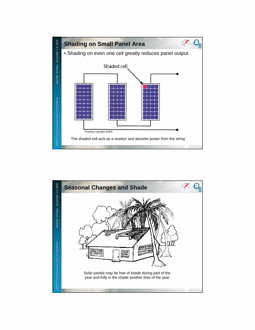
Shading on Small Panel AreaShading on Small Panel Area
• Shading on even one cell greatly reduces panel output
The shaded cell acts as a resistor and absorbs power from the string
Drawing copyright GSES
e8 /
PP
A D
SM
Wo
rksh
op
F
iji Is
lan
ds
No
vem
ber
2-6
, 200
9e8
/PP
A G
rid
Con
nect
ed S
olar
PV
Wor
ksho
p
R
epub
le8
/PP
A G
rid
Con
nect
ed S
olar
PV
Wor
ksho
p
R
epub
l ic o
f Pal
au
ic o
f Pal
au --
Nov
embe
r 1
Nov
embe
r 1 --
5, 2
010
5, 2
010
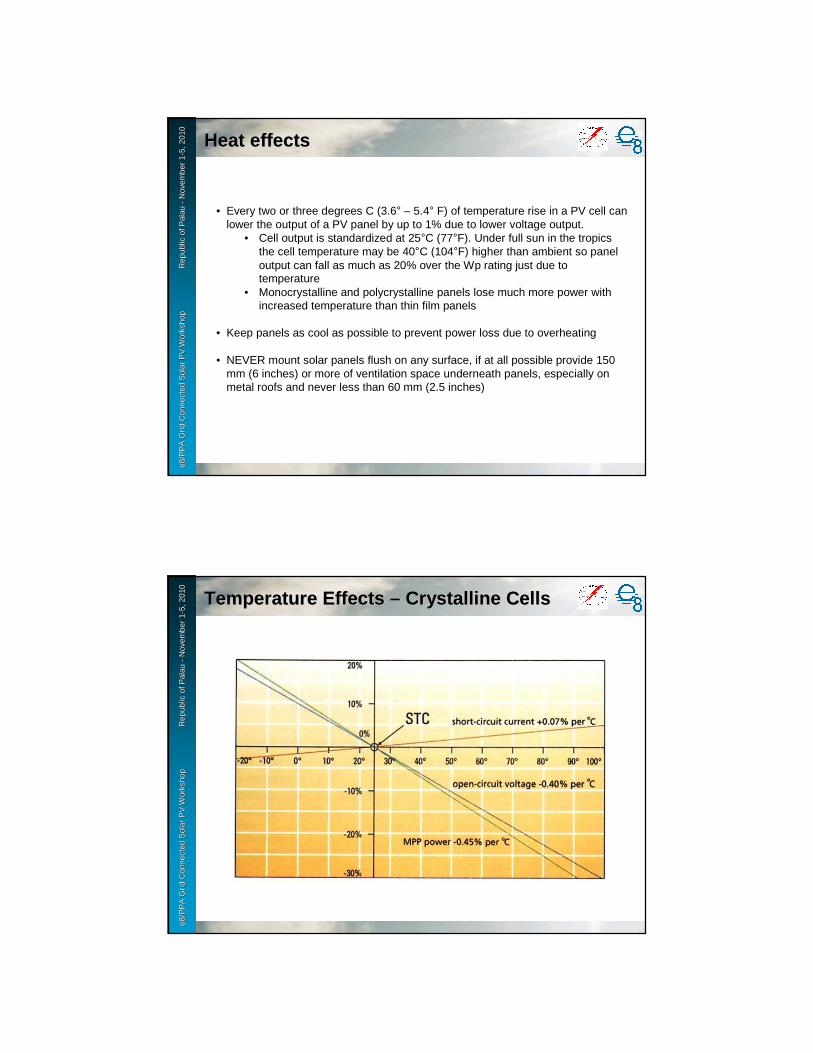
Seasonal Changes and ShadeSeasonal Changes and Shade
Solar panels may be free of shade during part of the year and fully in the shade another time of the year
e8 /
PP
A D
SM
Wo
rksh
op
F
iji Is
lan
ds
No
vem
ber
2-6
, 200
9e8
/PP
A G
rid
Con
nect
ed S
olar
PV
Wor
ksho
p
R
epub
le8
/PP
A G
rid
Con
nect
ed S
olar
PV
Wor
ksho
p
R
epub
l ic o
f Pal
au
ic o
f Pal
au --
Nov
embe
r 1
Nov
embe
r 1 --
5, 2
010
5, 2
010
Heat effectsHeat effects
• Every two or three degrees C (3.6° – 5.4° F) of temperature rise in a PV cell can lower the output of a PV panel by up to 1% due to lower voltage output.
• Cell output is standardized at 25°C (77°F). Under full sun in the tropics the cell temperature may be 40°C (104°F) higher than ambient so panel output can fall as much as 20% over the Wp rating just due to temperature
• Monocrystalline and polycrystalline panels lose much more power with increased temperature than thin film panels
• Keep panels as cool as possible to prevent power loss due to overheating
• NEVER mount solar panels flush on any surface, if at all possible provide 150 mm (6 inches) or more of ventilation space underneath panels, especially on metal roofs and never less than 60 mm (2.5 inches)
e8 /
PP
A D
SM
Wo
rksh
op
F
iji Is
lan
ds
No
vem
ber
2-6
, 200
9e8
/PP
A G
rid
Con
nect
ed S
olar
PV
Wor
ksho
p
R
epub
le8
/PP
A G
rid
Con
nect
ed S
olar
PV
Wor
ksho
p
R
epub
l ic o
f Pal
au
ic o
f Pal
au --
Nov
embe
r 1
Nov
embe
r 1 --
5, 2
010
5, 2
010
Temperature Effects Temperature Effects –– Crystalline CellsCrystalline Cells

e8 /
PP
A D
SM
Wo
rksh
op
F
iji Is
lan
ds
No
vem
ber
2-6
, 200
9e8
/PP
A G
rid
Con
nect
ed S
olar
PV
Wor
ksho
p
R
epub
le8
/PP
A G
rid
Con
nect
ed S
olar
PV
Wor
ksho
p
R
epub
l ic o
f Pal
au
ic o
f Pal
au --
Nov
embe
r 1
Nov
embe
r 1 --
5, 2
010
5, 2
010
Spacing Under Panels for VentilationSpacing Under Panels for Ventilation
Panels mounted on rails to provide space for ventilation
e8 /
PP
A D
SM
Wo
rksh
op
F
iji Is
lan
ds
No
vem
ber
2-6
, 200
9e8
/PP
A G
rid
Con
nect
ed S
olar
PV
Wor
ksho
p
R
epub
le8
/PP
A G
rid
Con
nect
ed S
olar
PV
Wor
ksho
p
R
epub
l ic o
f Pal
au
ic o
f Pal
au --
Nov
embe
r 1
Nov
embe
r 1 --
5, 2
010
5, 2
010
Crystalline panel voltage and current changes with temperature
Drawing copyright GSES
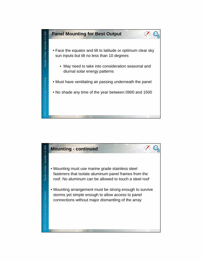
e8 /
PP
A D
SM
Wo
rksh
op
F
iji Is
lan
ds
No
vem
ber
2-6
, 200
9e8
/PP
A G
rid
Con
nect
ed S
olar
PV
Wor
ksho
p
R
epub
le8
/PP
A G
rid
Con
nect
ed S
olar
PV
Wor
ksho
p
R
epub
l ic o
f Pal
au
ic o
f Pal
au --
Nov
embe
r 1
Nov
embe
r 1 --
5, 2
010
5, 2
010
Panel Mounting for Best OutputPanel Mounting for Best Output
• Face the equator and tilt to latitude or optimum clear sky sun inputs but tilt no less than 10 degrees
• May need to take into consideration seasonal and diurnal solar energy patterns
• Must have ventilating air passing underneath the panel
• No shade any time of the year between 0900 and 1500
e8 /
PP
A D
SM
Wo
rksh
op
F
iji Is
lan
ds
No
vem
ber
2-6
, 200
9e8
/PP
A G
rid
Con
nect
ed S
olar
PV
Wor
ksho
p
R
epub
le8
/PP
A G
rid
Con
nect
ed S
olar
PV
Wor
ksho
p
R
epub
l ic o
f Pal
au
ic o
f Pal
au --
Nov
embe
r 1
Nov
embe
r 1 --
5, 2
010
5, 2
010
Mounting Mounting -- continuedcontinued
• Mounting must use marine grade stainless steel fasteners that isolate aluminum panel frames from the roof. No aluminum can be allowed to touch a steel roof
• Mounting arrangement must be strong enough to survive storms yet simple enough to allow access to panel connections without major dismantling of the array
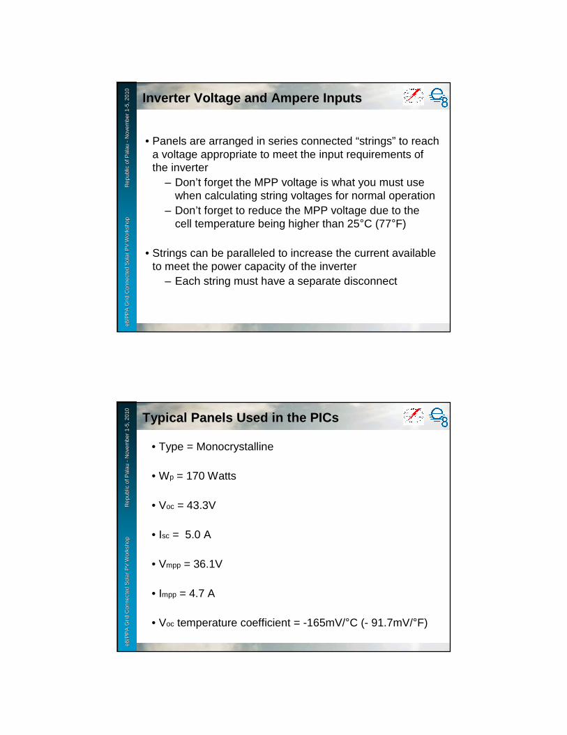
e8 /
PP
A D
SM
Wo
rksh
op
F
iji Is
lan
ds
No
vem
ber
2-6
, 200
9e8
/PP
A G
rid
Con
nect
ed S
olar
PV
Wor
ksho
p
R
epub
le8
/PP
A G
rid
Con
nect
ed S
olar
PV
Wor
ksho
p
R
epub
l ic o
f Pal
au
ic o
f Pal
au --
Nov
embe
r 1
Nov
embe
r 1 --
5, 2
010
5, 2
010
Inverter Voltage and Ampere InputsInverter Voltage and Ampere Inputs
• Panels are arranged in series connected “strings” to reach a voltage appropriate to meet the input requirements of the inverter
– Don’t forget the MPP voltage is what you must use when calculating string voltages for normal operation
– Don’t forget to reduce the MPP voltage due to the cell temperature being higher than 25°C (77°F)
• Strings can be paralleled to increase the current available to meet the power capacity of the inverter
– Each string must have a separate disconnect
e8 /
PP
A D
SM
Wo
rksh
op
F
iji Is
lan
ds
No
vem
ber
2-6
, 200
9e8
/PP
A G
rid
Con
nect
ed S
olar
PV
Wor
ksho
p
R
epub
le8
/PP
A G
rid
Con
nect
ed S
olar
PV
Wor
ksho
p
R
epub
l ic o
f Pal
au
ic o
f Pal
au --
Nov
embe
r 1
Nov
embe
r 1 --
5, 2
010
5, 2
010
Typical Panels Used in the PICsTypical Panels Used in the PICs
• Type = Monocrystalline
• Wp = 170 Watts
• Voc = 43.3V
• Isc = 5.0 A
• Vmpp = 36.1V
• Impp = 4.7 A
• Voc temperature coefficient = -165mV/°C (- 91.7mV/°F)

1
Day Day 22


Grid Connected Solar PV WorkshopRepublic of Palau
November 1-5,2010
Grid-Connected Solar PV – Invertersand Strings
Dr. Herbert A. WadeDr. Herbert A. Wade
e8 /
PP
A D
SM
Wo
rksh
op
F
iji Is
lan
ds
No
vem
ber
2-6
, 200
9e8
/PP
A G
rid
Con
nect
ed S
olar
PV
Wor
ksho
p
R
epub
le8
/PP
A G
rid
Con
nect
ed S
olar
PV
Wor
ksho
p
R
epub
l ic o
f Pal
au
ic o
f Pal
au --
Nov
embe
r 1
Nov
embe
r 1 --
5, 2
010
5, 2
010
Inverter Characteristics and SpecificationsInverter Characteristics and Specifications

e8 /
PP
A D
SM
Wo
rksh
op
F
iji Is
lan
ds
No
vem
ber
2-6
, 200
9e8
/PP
A G
rid
Con
nect
ed S
olar
PV
Wor
ksho
p
R
epub
le8
/PP
A G
rid
Con
nect
ed S
olar
PV
Wor
ksho
p
R
epub
l ic o
f Pal
au
ic o
f Pal
au --
Nov
embe
r 1
Nov
embe
r 1 --
5, 2
010
5, 2
010
AntiAnti --IslandingIslanding
• Islanding refers to the idea of a PV system generating power for input to the grid when the main grid supply is off
– The creation of an “island” of power– Serious safety hazard if a PV system “islands”
• Multiple redundant circuits prevent islanding– Voltage excursions beyond the acceptable range– Frequency excursions beyond the acceptable range– Rate of voltage change– Rate of frequency change– Effective loading
e8 /
PP
A D
SM
Wo
rksh
op
F
iji Is
lan
ds
No
vem
ber
2-6
, 200
9e8
/PP
A G
rid
Con
nect
ed S
olar
PV
Wor
ksho
p
R
epub
le8
/PP
A G
rid
Con
nect
ed S
olar
PV
Wor
ksho
p
R
epub
l ic o
f Pal
au
ic o
f Pal
au --
Nov
embe
r 1
Nov
embe
r 1 --
5, 2
010
5, 2
010
• Millions of grid connected inverters are in service and islanding has not been a problem
� Inverters must be certified for anti-islanding by an international certification body� Never allow the use of uncertified inverters
� Where there are few installations in service, utilities that are not familiar with the exemplary safety record for certified inverters may choose to manually disconnect PV systems from the grid when the grid is going to be serviced.

e8 /
PP
A D
SM
Wo
rksh
op
F
iji Is
lan
ds
No
vem
ber
2-6
, 200
9e8
/PP
A G
rid
Con
nect
ed S
olar
PV
Wor
ksho
p
R
epub
le8
/PP
A G
rid
Con
nect
ed S
olar
PV
Wor
ksho
p
R
epub
l ic o
f Pal
au
ic o
f Pal
au --
Nov
embe
r 1
Nov
embe
r 1 --
5, 2
010
5, 2
010
General Types of Inverter InstallationsGeneral Types of Inverter Installations
• Single large inverter for the entire installation– May be single phase or three phase– Often custom made and not locally maintainable– Common in Japan and the USA
• Multiple smaller inverters connected in parallel– Rapidly becoming the international standard
� Common in Europe– One inverter fails and only a part of the output is lost– Spare parts are not expensive and are easily stocked for
quick replacement– Maintenance does not require special skills or training
for the specific type of inverter being used– Slightly higher overall cost than a single large inverter
but the life cycle cost is lower for the Pacific Islands due to the cost of repair and shipping for single large inverters
e8 /
PP
A D
SM
Wo
rksh
op
F
iji Is
lan
ds
No
vem
ber
2-6
, 200
9e8
/PP
A G
rid
Con
nect
ed S
olar
PV
Wor
ksho
p
R
epub
le8
/PP
A G
rid
Con
nect
ed S
olar
PV
Wor
ksho
p
R
epub
l ic o
f Pal
au
ic o
f Pal
au --
Nov
embe
r 1
Nov
embe
r 1 --
5, 2
010
5, 2
010 Inverters Chosen for NDBP in PalauInverters Chosen for NDBP in Palau
SMA Sunny Boy 3000USSMA Sunny Boy 3000US
�Utilities that follow USA power standards must be sure to buyinverters that follow US power standards and US solar standards.
Most non US made inverters can be programmed to fit US standards butMay have peculiarities that make the grid connection difficult for residences.

e8 /
PP
A D
SM
Wo
rksh
op
F
iji Is
lan
ds
No
vem
ber
2-6
, 200
9e8
/PP
A G
rid
Con
nect
ed S
olar
PV
Wor
ksho
p
R
epub
le8
/PP
A G
rid
Con
nect
ed S
olar
PV
Wor
ksho
p
R
epub
l ic o
f Pal
au
ic o
f Pal
au --
Nov
embe
r 1
Nov
embe
r 1 --
5, 2
010
5, 2
010
e8 /
PP
A D
SM
Wo
rksh
op
F
iji Is
lan
ds
No
vem
ber
2-6
, 200
9e8
/PP
A G
rid
Con
nect
ed S
olar
PV
Wor
ksho
p
R
epub
le8
/PP
A G
rid
Con
nect
ed S
olar
PV
Wor
ksho
p
R
epub
l ic o
f Pal
au
ic o
f Pal
au --
Nov
embe
r 1
Nov
embe
r 1 --
5, 2
010
5, 2
010
Primary SpecificationsPrimary Specifications
• DC input voltage range– Rarely below 100V and may go as high as 1000V
� The number of panels in a string must be sufficient for the MPP string output voltage to never go below the minimum for the inverter after voltage reduction due to temperature is considered.
� The number of panels in a string must not exceed the number needed to reach the maximum MPP allowable voltage for the inverter before voltage reduction due to temperature is considered.
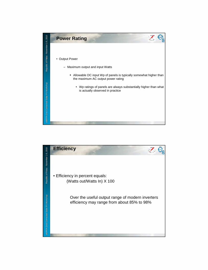
e8 /
PP
A D
SM
Wo
rksh
op
F
iji Is
lan
ds
No
vem
ber
2-6
, 200
9e8
/PP
A G
rid
Con
nect
ed S
olar
PV
Wor
ksho
p
R
epub
le8
/PP
A G
rid
Con
nect
ed S
olar
PV
Wor
ksho
p
R
epub
l ic o
f Pal
au
ic o
f Pal
au --
Nov
embe
r 1
Nov
embe
r 1 --
5, 2
010
5, 2
010
• Output Power
– Maximum output and input Watts
� Allowable DC input Wp of panels is typically somewhat higher than the maximum AC output power rating
� Wp ratings of panels are always substantially higher than what is actually observed in practice
Power Rating
e8 /
PP
A D
SM
Wo
rksh
op
F
iji Is
lan
ds
No
vem
ber
2-6
, 200
9e8
/PP
A G
rid
Con
nect
ed S
olar
PV
Wor
ksho
p
R
epub
le8
/PP
A G
rid
Con
nect
ed S
olar
PV
Wor
ksho
p
R
epub
l ic o
f Pal
au
ic o
f Pal
au --
Nov
embe
r 1
Nov
embe
r 1 --
5, 2
010
5, 2
010 EfficiencyEfficiency
• Efficiency in percent equals:(Watts out/Watts In) X 100
Over the useful output range of modern inverters efficiency may range from about 85% to 98%
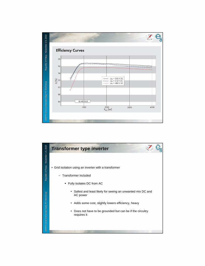
e8 /
PP
A D
SM
Wo
rksh
op
F
iji Is
lan
ds
No
vem
ber
2-6
, 200
9e8
/PP
A G
rid
Con
nect
ed S
olar
PV
Wor
ksho
p
R
epub
le8
/PP
A G
rid
Con
nect
ed S
olar
PV
Wor
ksho
p
R
epub
l ic o
f Pal
au
ic o
f Pal
au --
Nov
embe
r 1
Nov
embe
r 1 --
5, 2
010
5, 2
010
e8 /
PP
A D
SM
Wo
rksh
op
F
iji Is
lan
ds
No
vem
ber
2-6
, 200
9e8
/PP
A G
rid
Con
nect
ed S
olar
PV
Wor
ksho
p
R
epub
le8
/PP
A G
rid
Con
nect
ed S
olar
PV
Wor
ksho
p
R
epub
l ic o
f Pal
au
ic o
f Pal
au --
Nov
embe
r 1
Nov
embe
r 1 --
5, 2
010
5, 2
010
Transformer type inverterTransformer type inverter
• Grid isolation using an inverter with a transformer
– Transformer included
� Fully isolates DC from AC
� Safest and least likely for seeing an unwanted mix DC and AC power
� Adds some cost, slightly lowers efficiency, heavy
� Does not have to be grounded but can be if the circuitry requires it
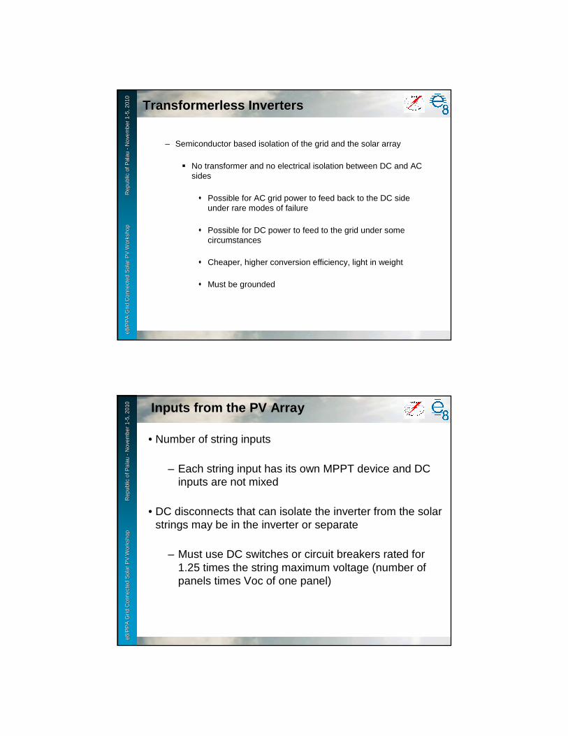
e8 /
PP
A D
SM
Wo
rksh
op
F
iji Is
lan
ds
No
vem
ber
2-6
, 200
9e8
/PP
A G
rid
Con
nect
ed S
olar
PV
Wor
ksho
p
R
epub
le8
/PP
A G
rid
Con
nect
ed S
olar
PV
Wor
ksho
p
R
epub
l ic o
f Pal
au
ic o
f Pal
au --
Nov
embe
r 1
Nov
embe
r 1 --
5, 2
010
5, 2
010
TransformerlessTransformerless InvertersInverters
– Semiconductor based isolation of the grid and the solar array
� No transformer and no electrical isolation between DC and AC sides
� Possible for AC grid power to feed back to the DC side under rare modes of failure
� Possible for DC power to feed to the grid under some circumstances
� Cheaper, higher conversion efficiency, light in weight
� Must be grounded
e8 /
PP
A D
SM
Wo
rksh
op
F
iji Is
lan
ds
No
vem
ber
2-6
, 200
9e8
/PP
A G
rid
Con
nect
ed S
olar
PV
Wor
ksho
p
R
epub
le8
/PP
A G
rid
Con
nect
ed S
olar
PV
Wor
ksho
p
R
epub
l ic o
f Pal
au
ic o
f Pal
au --
Nov
embe
r 1
Nov
embe
r 1 --
5, 2
010
5, 2
010
• Number of string inputs
– Each string input has its own MPPT device and DC inputs are not mixed
• DC disconnects that can isolate the inverter from the solar strings may be in the inverter or separate
– Must use DC switches or circuit breakers rated for 1.25 times the string maximum voltage (number of panels times Voc of one panel)
Inputs from the PV Array
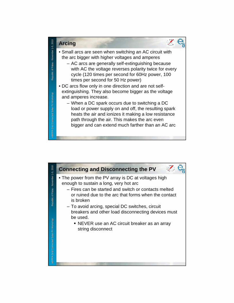
e8 /
PP
A D
SM
Wo
rksh
op
F
iji Is
lan
ds
No
vem
ber
2-6
, 200
9e8
/PP
A G
rid
Con
nect
ed S
olar
PV
Wor
ksho
p
R
epub
le8
/PP
A G
rid
Con
nect
ed S
olar
PV
Wor
ksho
p
R
epub
l ic o
f Pal
au
ic o
f Pal
au --
Nov
embe
r 1
Nov
embe
r 1 --
5, 2
010
5, 2
010
ArcingArcing
• Small arcs are seen when switching an AC circuit with the arc bigger with higher voltages and amperes
– AC arcs are generally self-extinguishing because with AC the voltage reverses polarity twice for every cycle (120 times per second for 60Hz power, 100 times per second for 50 Hz power)
• DC arcs flow only in one direction and are not self-extinguishing. They also become bigger as the voltage and amperes increase.
– When a DC spark occurs due to switching a DC load or power supply on and off, the resulting spark heats the air and ionizes it making a low resistance path through the air. This makes the arc even bigger and can extend much farther than an AC arc
e8 /
PP
A D
SM
Wo
rksh
op
F
iji Is
lan
ds
No
vem
ber
2-6
, 200
9e8
/PP
A G
rid
Con
nect
ed S
olar
PV
Wor
ksho
p
R
epub
le8
/PP
A G
rid
Con
nect
ed S
olar
PV
Wor
ksho
p
R
epub
l ic o
f Pal
au
ic o
f Pal
au --
Nov
embe
r 1
Nov
embe
r 1 --
5, 2
010
5, 2
010
Connecting and Disconnecting the PVConnecting and Disconnecting the PV
• The power from the PV array is DC at voltages high enough to sustain a long, very hot arc
– Fires can be started and switch or contacts melted or ruined due to the arc that forms when the contact is broken
– To avoid arcing, special DC switches, circuit breakers and other load disconnecting devices must be used.� NEVER use an AC circuit breaker as an array
string disconnect

e8 /
PP
A D
SM
Wo
rksh
op
F
iji Is
lan
ds
No
vem
ber
2-6
, 200
9e8
/PP
A G
rid
Con
nect
ed S
olar
PV
Wor
ksho
p
R
epub
le8
/PP
A G
rid
Con
nect
ed S
olar
PV
Wor
ksho
p
R
epub
l ic o
f Pal
au
ic o
f Pal
au --
Nov
embe
r 1
Nov
embe
r 1 --
5, 2
010
5, 2
010
Arcing at the NDBP inverter (slow motion)Arcing at the NDBP inverter (slow motion)
Do not try this at home……
e8 /
PP
A D
SM
Wo
rksh
op
F
iji Is
lan
ds
No
vem
ber
2-6
, 200
9e8
/PP
A G
rid
Con
nect
ed S
olar
PV
Wor
ksho
p
R
epub
le8
/PP
A G
rid
Con
nect
ed S
olar
PV
Wor
ksho
p
R
epub
l ic o
f Pal
au
ic o
f Pal
au --
Nov
embe
r 1
Nov
embe
r 1 --
5, 2
010
5, 2
010
AC DisconnectAC Disconnect
• AC disconnects may in the inverter or separate
– May be a standard circuit breaker at least 25% higher in capacity than the maximum Amperes that the inverter can deliver to the grid
– Should be lockable (switch or the box cover) for safety purpose
– Should be located near the inverter for safety and convenience of maintenance (the utility may require a second disconnect at the meter)

e8 /
PP
A D
SM
Wo
rksh
op
F
iji Is
lan
ds
No
vem
ber
2-6
, 200
9e8
/PP
A G
rid
Con
nect
ed S
olar
PV
Wor
ksho
p
R
epub
le8
/PP
A G
rid
Con
nect
ed S
olar
PV
Wor
ksho
p
R
epub
l ic o
f Pal
au
ic o
f Pal
au --
Nov
embe
r 1
Nov
embe
r 1 --
5, 2
010
5, 2
010
Inverter Data AccessInverter Data Access
• Data delivery mechanism
– Usually data is through a LAN type cable with a standard computer interface
� May be included in the inverter or may require an additional plug in card to be inserted in the inverter
� Unless there is a data logger attached (e.g. the SMA “Webbox”) or there is a computer dedicated to collecting inverter data connected to the data line, only recent data will be available
e8 /
PP
A D
SM
Wo
rksh
op
F
iji Is
lan
ds
No
vem
ber
2-6
, 200
9e8
/PP
A G
rid
Con
nect
ed S
olar
PV
Wor
ksho
p
R
epub
le8
/PP
A G
rid
Con
nect
ed S
olar
PV
Wor
ksho
p
R
epub
l ic o
f Pal
au
ic o
f Pal
au --
Nov
embe
r 1
Nov
embe
r 1 --
5, 2
010
5, 2
010
Data Available from the InverterData Available from the Inverter
• Most quality inverters make available at least– Date and time of data packet– Amperes coming from each PV string– Voltage at each string– AC Watts or VA from the Inverter– kWh delivered to the grid since installation– Status of the inverter (standby, off line, delivering
power to the grid, etc.)– Any error conditions that currently exist
• Other data that may be available may include– Heatsink temperature– Fan operation– Time and date of last restart
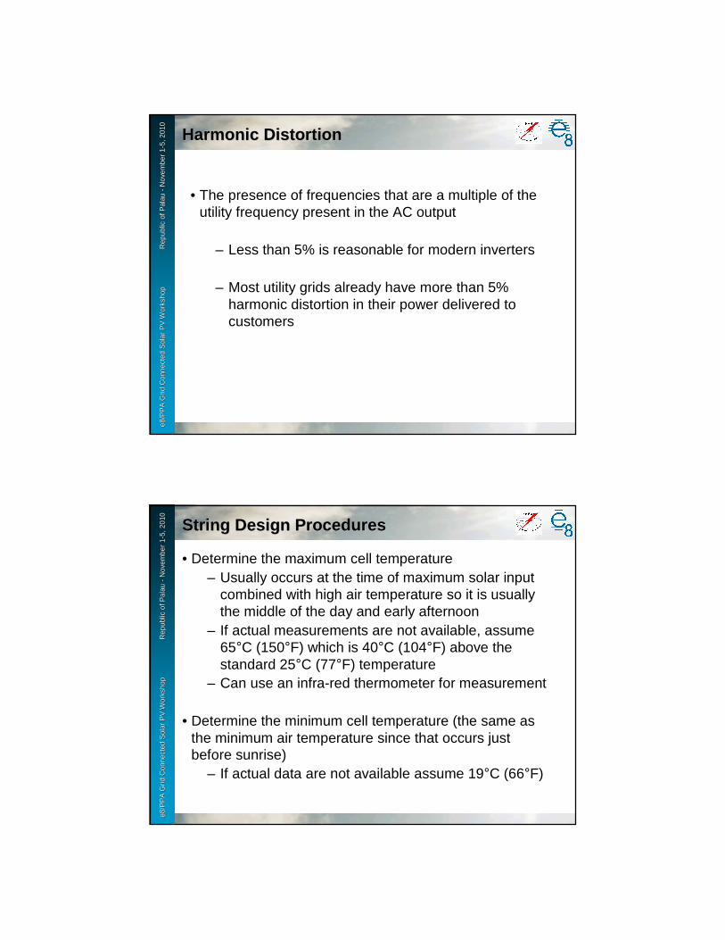
e8 /
PP
A D
SM
Wo
rksh
op
F
iji Is
lan
ds
No
vem
ber
2-6
, 200
9e8
/PP
A G
rid
Con
nect
ed S
olar
PV
Wor
ksho
p
R
epub
le8
/PP
A G
rid
Con
nect
ed S
olar
PV
Wor
ksho
p
R
epub
l ic o
f Pal
au
ic o
f Pal
au --
Nov
embe
r 1
Nov
embe
r 1 --
5, 2
010
5, 2
010
Harmonic DistortionHarmonic Distortion
• The presence of frequencies that are a multiple of the utility frequency present in the AC output
– Less than 5% is reasonable for modern inverters
– Most utility grids already have more than 5% harmonic distortion in their power delivered to customers
e8 /
PP
A D
SM
Wo
rksh
op
F
iji Is
lan
ds
No
vem
ber
2-6
, 200
9e8
/PP
A G
rid
Con
nect
ed S
olar
PV
Wor
ksho
p
R
epub
le8
/PP
A G
rid
Con
nect
ed S
olar
PV
Wor
ksho
p
R
epub
l ic o
f Pal
au
ic o
f Pal
au --
Nov
embe
r 1
Nov
embe
r 1 --
5, 2
010
5, 2
010
String Design ProceduresString Design Procedures
• Determine the maximum cell temperature– Usually occurs at the time of maximum solar input
combined with high air temperature so it is usually the middle of the day and early afternoon
– If actual measurements are not available, assume 65°C (150°F) which is 40°C (104°F) above the standard 25°C (77°F) temperature
– Can use an infra-red thermometer for measurement
• Determine the minimum cell temperature (the same as the minimum air temperature since that occurs just before sunrise)
– If actual data are not available assume 19°C (66°F)
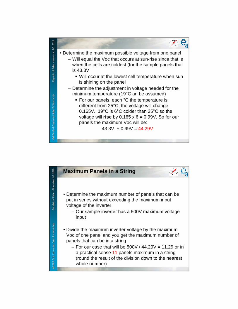
e8 /
PP
A D
SM
Wo
rksh
op
F
iji Is
lan
ds
No
vem
ber
2-6
, 200
9e8
/PP
A G
rid
Con
nect
ed S
olar
PV
Wor
ksho
p
R
epub
le8
/PP
A G
rid
Con
nect
ed S
olar
PV
Wor
ksho
p
R
epub
l ic o
f Pal
au
ic o
f Pal
au --
Nov
embe
r 1
Nov
embe
r 1 --
5, 2
010
5, 2
010
• Determine the maximum possible voltage from one panel– Will equal the Voc that occurs at sun-rise since that is
when the cells are coldest (for the sample panels that is 43.3V� Will occur at the lowest cell temperature when sun
is shining on the panel– Determine the adjustment in voltage needed for the
minimum temperature (19°C an be assumed)� For our panels, each °C the temperature is
different from 25°C, the voltage will change 0.165V. 19°C is 6°C colder than 25°C so the voltage will rise by 0.165 x 6 = 0.99V. So for our panels the maximum Voc will be:
43.3V + 0.99V = 44.29V
e8 /
PP
A D
SM
Wo
rksh
op
F
iji Is
lan
ds
No
vem
ber
2-6
, 200
9e8
/PP
A G
rid
Con
nect
ed S
olar
PV
Wor
ksho
p
R
epub
le8
/PP
A G
rid
Con
nect
ed S
olar
PV
Wor
ksho
p
R
epub
l ic o
f Pal
au
ic o
f Pal
au --
Nov
embe
r 1
Nov
embe
r 1 --
5, 2
010
5, 2
010
• Determine the maximum number of panels that can be put in series without exceeding the maximum input voltage of the inverter
– Our sample inverter has a 500V maximum voltage input
• Divide the maximum inverter voltage by the maximum Voc of one panel and you get the maximum number of panels that can be in a string
– For our case that will be 500V / 44.29V = 11.29 or in a practical sense 11 panels maximum in a string (round the result of the division down to the nearest whole number)
Maximum Panels in a String
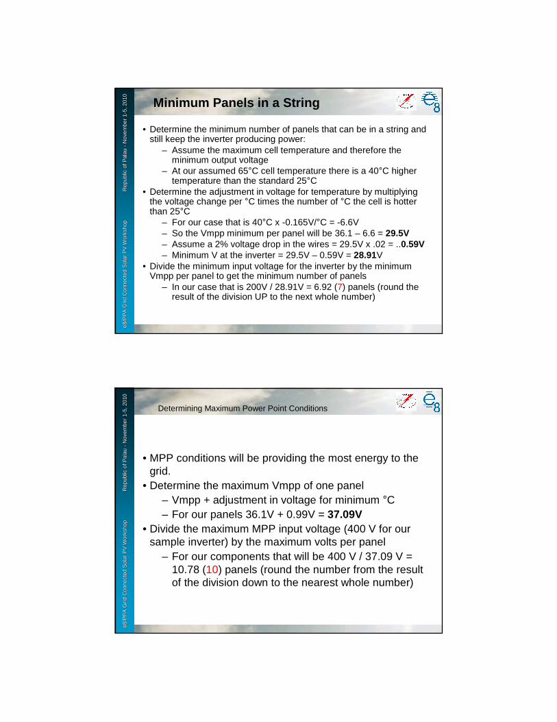
e8 /
PP
A D
SM
Wo
rksh
op
F
iji Is
lan
ds
No
vem
ber
2-6
, 200
9e8
/PP
A G
rid
Con
nect
ed S
olar
PV
Wor
ksho
p
R
epub
le8
/PP
A G
rid
Con
nect
ed S
olar
PV
Wor
ksho
p
R
epub
l ic o
f Pal
au
ic o
f Pal
au --
Nov
embe
r 1
Nov
embe
r 1 --
5, 2
010
5, 2
010
• Determine the minimum number of panels that can be in a string and still keep the inverter producing power:
– Assume the maximum cell temperature and therefore the minimum output voltage
– At our assumed 65°C cell temperature there is a 40°C higher temperature than the standard 25°C
• Determine the adjustment in voltage for temperature by multiplying the voltage change per °C times the number of °C the cell is hotter than 25°C
– For our case that is 40°C x -0.165V/°C = -6.6V– So the Vmpp minimum per panel will be 36.1 – 6.6 = 29.5V– Assume a 2% voltage drop in the wires = 29.5V x .02 = ..0.59V– Minimum V at the inverter = 29.5V – 0.59V = 28.91V
• Divide the minimum input voltage for the inverter by the minimumVmpp per panel to get the minimum number of panels
– In our case that is 200V / 28.91V = 6.92 (7) panels (round the result of the division UP to the next whole number)
Minimum Panels in a String
e8 /
PP
A D
SM
Wo
rksh
op
F
iji Is
lan
ds
No
vem
ber
2-6
, 200
9e8
/PP
A G
rid
Con
nect
ed S
olar
PV
Wor
ksho
p
R
epub
le8
/PP
A G
rid
Con
nect
ed S
olar
PV
Wor
ksho
p
R
epub
l ic o
f Pal
au
ic o
f Pal
au --
Nov
embe
r 1
Nov
embe
r 1 --
5, 2
010
5, 2
010
• MPP conditions will be providing the most energy to the grid.
• Determine the maximum Vmpp of one panel– Vmpp + adjustment in voltage for minimum °C– For our panels 36.1V + 0.99V = 37.09V
• Divide the maximum MPP input voltage (400 V for our sample inverter) by the maximum volts per panel
– For our components that will be 400 V / 37.09 V = 10.78 (10) panels (round the number from the result of the division down to the nearest whole number)
Determining Maximum Power Point Conditions
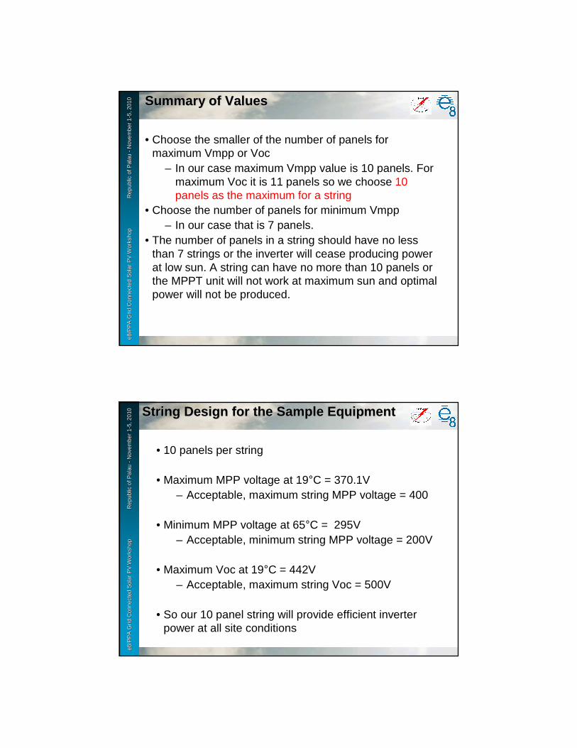
e8 /
PP
A D
SM
Wo
rksh
op
F
iji Is
lan
ds
No
vem
ber
2-6
, 200
9e8
/PP
A G
rid
Con
nect
ed S
olar
PV
Wor
ksho
p
R
epub
le8
/PP
A G
rid
Con
nect
ed S
olar
PV
Wor
ksho
p
R
epub
l ic o
f Pal
au
ic o
f Pal
au --
Nov
embe
r 1
Nov
embe
r 1 --
5, 2
010
5, 2
010 Summary of ValuesSummary of Values
• Choose the smaller of the number of panels for maximum Vmpp or Voc
– In our case maximum Vmpp value is 10 panels. For maximum Voc it is 11 panels so we choose 10 panels as the maximum for a string
• Choose the number of panels for minimum Vmpp– In our case that is 7 panels.
• The number of panels in a string should have no less than 7 strings or the inverter will cease producing power at low sun. A string can have no more than 10 panels or the MPPT unit will not work at maximum sun and optimal power will not be produced.
e8 /
PP
A D
SM
Wo
rksh
op
F
iji Is
lan
ds
No
vem
ber
2-6
, 200
9e8
/PP
A G
rid
Con
nect
ed S
olar
PV
Wor
ksho
p
R
epub
le8
/PP
A G
rid
Con
nect
ed S
olar
PV
Wor
ksho
p
R
epub
l ic o
f Pal
au
ic o
f Pal
au --
Nov
embe
r 1
Nov
embe
r 1 --
5, 2
010
5, 2
010 String Design for the Sample EquipmentString Design for the Sample Equipment
• 10 panels per string
• Maximum MPP voltage at 19°C = 370.1V– Acceptable, maximum string MPP voltage = 400
• Minimum MPP voltage at 65°C = 295V– Acceptable, minimum string MPP voltage = 200V
• Maximum Voc at 19°C = 442V– Acceptable, maximum string Voc = 500V
• So our 10 panel string will provide efficient inverter power at all site conditions
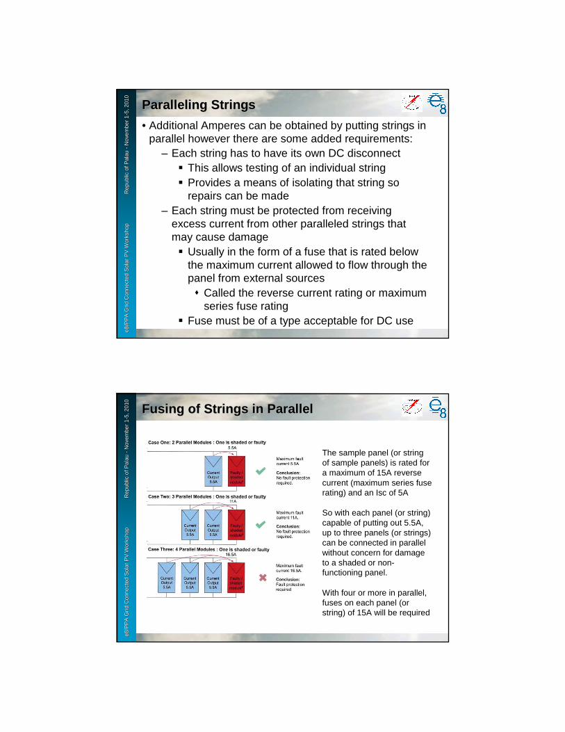
e8 /
PP
A D
SM
Wo
rksh
op
F
iji Is
lan
ds
No
vem
ber
2-6
, 200
9e8
/PP
A G
rid
Con
nect
ed S
olar
PV
Wor
ksho
p
R
epub
le8
/PP
A G
rid
Con
nect
ed S
olar
PV
Wor
ksho
p
R
epub
l ic o
f Pal
au
ic o
f Pal
au --
Nov
embe
r 1
Nov
embe
r 1 --
5, 2
010
5, 2
010
Paralleling StringsParalleling Strings
• Additional Amperes can be obtained by putting strings in parallel however there are some added requirements:
– Each string has to have its own DC disconnect� This allows testing of an individual string� Provides a means of isolating that string so
repairs can be made– Each string must be protected from receiving
excess current from other paralleled strings that may cause damage� Usually in the form of a fuse that is rated below
the maximum current allowed to flow through the panel from external sources� Called the reverse current rating or maximum
series fuse rating� Fuse must be of a type acceptable for DC use
e8 /
PP
A D
SM
Wo
rksh
op
F
iji Is
lan
ds
No
vem
ber
2-6
, 200
9e8
/PP
A G
rid
Con
nect
ed S
olar
PV
Wor
ksho
p
R
epub
le8
/PP
A G
rid
Con
nect
ed S
olar
PV
Wor
ksho
p
R
epub
l ic o
f Pal
au
ic o
f Pal
au --
Nov
embe
r 1
Nov
embe
r 1 --
5, 2
010
5, 2
010
Fusing of Strings in ParallelFusing of Strings in Parallel
The sample panel (or string of sample panels) is rated for a maximum of 15A reverse current (maximum series fuse rating) and an Isc of 5A
So with each panel (or string) capable of putting out 5.5A, up to three panels (or strings) can be connected in parallel without concern for damage to a shaded or non-functioning panel.
With four or more in parallel, fuses on each panel (or string) of 15A will be required

e8 /
PP
A D
SM
Wo
rksh
op
F
iji Is
lan
ds
No
vem
ber
2-6
, 200
9e8
/PP
A G
rid
Con
nect
ed S
olar
PV
Wor
ksho
p
R
epub
le8
/PP
A G
rid
Con
nect
ed S
olar
PV
Wor
ksho
p
R
epub
l ic o
f Pal
au
ic o
f Pal
au --
Nov
embe
r 1
Nov
embe
r 1 --
5, 2
010
5, 2
010
Layout of Panel WiringLayout of Panel Wiring
• To minimize damaging voltage surges caused by nearby lightning strikes, string wiring must not include any open loops
6 panel string wiredwith an open loop
6 panel string wired to minimizelightning induced voltage surges
INCORRECT
CORRECT
e8 /
PP
A D
SM
Wo
rksh
op
F
iji Is
lan
ds
No
vem
ber
2-6
, 200
9e8
/PP
A G
rid
Con
nect
ed S
olar
PV
Wor
ksho
p
R
epub
le8
/PP
A G
rid
Con
nect
ed S
olar
PV
Wor
ksho
p
R
epub
l ic o
f Pal
au
ic o
f Pal
au --
Nov
embe
r 1
Nov
embe
r 1 --
5, 2
010
5, 2
010
Balance of System ComponentsBalance of System Components
• Besides the panels and inverter, additional components are needed to comply with safety and operational requirements:
– A DC disconnect for each string� Whether strings go directly to the inverter or are
paralleled with other strings, each string requires its own DC disconnect

e8 /
PP
A D
SM
Wo
rksh
op
F
iji Is
lan
ds
No
vem
ber
2-6
, 200
9e8
/PP
A G
rid
Con
nect
ed S
olar
PV
Wor
ksho
p
R
epub
le8
/PP
A G
rid
Con
nect
ed S
olar
PV
Wor
ksho
p
R
epub
l ic o
f Pal
au
ic o
f Pal
au --
Nov
embe
r 1
Nov
embe
r 1 --
5, 2
010
5, 2
010
Overall Design for a Residence (3.4 kWp)Overall Design for a Residence (3.4 kWp)
• One SMA SB3000US inverter
• Two strings of 10 – 170 Wp monocrystalline panels– Each feeding a separate inverter input
• Two DC disconnects (one for each string)
• One AC disconnect near the inverter– The utility may require an additional one near the
meter
e8 /
PP
A D
SM
Wo
rksh
op
F
iji Is
lan
ds
No
vem
ber
2-6
, 200
9e8
/PP
A G
rid
Con
nect
ed S
olar
PV
Wor
ksho
p
R
epub
le8
/PP
A G
rid
Con
nect
ed S
olar
PV
Wor
ksho
p
R
epub
l ic o
f Pal
au
ic o
f Pal
au --
Nov
embe
r 1
Nov
embe
r 1 --
5, 2
010
5, 2
010
Power RequirementPower Requirement
• Each panel is 170Wp in size but derated due to high temperature (which occurs at peak solar input) to:
29.5Vmpp x 4.7Ampp = 138.65 Wp• Each string input allows for 1875 Watts input• So at mid-day the maximum input power from the 10
panel string = 10 x 138.65 = 1386.5Wp– Proposed design is within an acceptable power
range
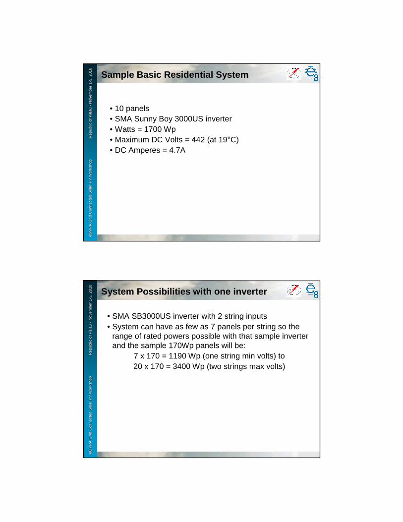
e8 /
PP
A D
SM
Wo
rksh
op
F
iji Is
lan
ds
No
vem
ber
2-6
, 200
9e8
/PP
A G
rid
Con
nect
ed S
olar
PV
Wor
ksho
p
R
epub
le8
/PP
A G
rid
Con
nect
ed S
olar
PV
Wor
ksho
p
R
epub
l ic o
f Pal
au
ic o
f Pal
au --
Nov
embe
r 1
Nov
embe
r 1 --
5, 2
010
5, 2
010
Sample Basic Residential SystemSample Basic Residential System
• 10 panels• SMA Sunny Boy 3000US inverter• Watts = 1700 Wp• Maximum DC Volts = 442 (at 19°C)• DC Amperes = 4.7A
e8 /
PP
A D
SM
Wo
rksh
op
F
iji Is
lan
ds
No
vem
ber
2-6
, 200
9e8
/PP
A G
rid
Con
nect
ed S
olar
PV
Wor
ksho
p
R
epub
le8
/PP
A G
rid
Con
nect
ed S
olar
PV
Wor
ksho
p
R
epub
l ic o
f Pal
au
ic o
f Pal
au --
Nov
embe
r 1
Nov
embe
r 1 --
5, 2
010
5, 2
010
System Possibilities with one inverterSystem Possibilities with one inverter
• SMA SB3000US inverter with 2 string inputs• System can have as few as 7 panels per string so the
range of rated powers possible with that sample inverter and the sample 170Wp panels will be:
7 x 170 = 1190 Wp (one string min volts) to20 x 170 = 3400 Wp (two strings max volts)
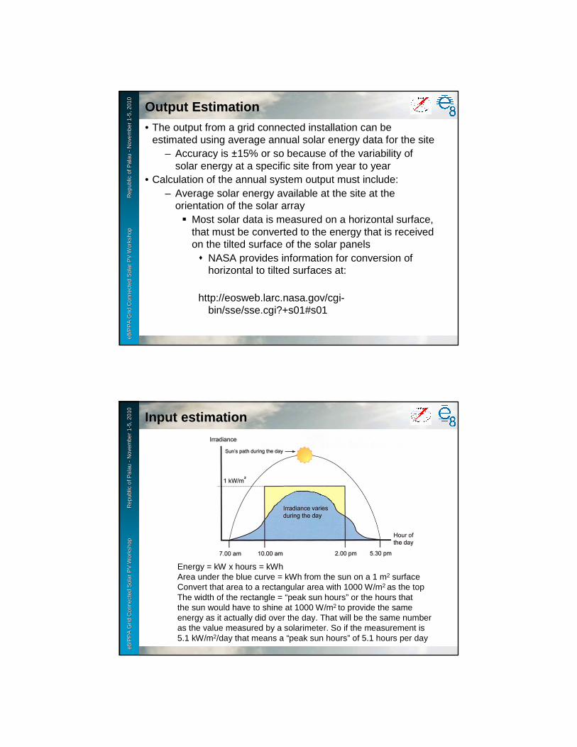
e8 /
PP
A D
SM
Wo
rksh
op
F
iji Is
lan
ds
No
vem
ber
2-6
, 200
9e8
/PP
A G
rid
Con
nect
ed S
olar
PV
Wor
ksho
p
R
epub
le8
/PP
A G
rid
Con
nect
ed S
olar
PV
Wor
ksho
p
R
epub
l ic o
f Pal
au
ic o
f Pal
au --
Nov
embe
r 1
Nov
embe
r 1 --
5, 2
010
5, 2
010
Output EstimationOutput Estimation• The output from a grid connected installation can be
estimated using average annual solar energy data for the site– Accuracy is ±15% or so because of the variability of
solar energy at a specific site from year to year• Calculation of the annual system output must include:
– Average solar energy available at the site at the orientation of the solar array� Most solar data is measured on a horizontal surface,
that must be converted to the energy that is received on the tilted surface of the solar panels� NASA provides information for conversion of
horizontal to tilted surfaces at:
http://eosweb.larc.nasa.gov/cgi-bin/sse/sse.cgi?+s01#s01
e8 /
PP
A D
SM
Wo
rksh
op
F
iji Is
lan
ds
No
vem
ber
2-6
, 200
9e8
/PP
A G
rid
Con
nect
ed S
olar
PV
Wor
ksho
p
R
epub
le8
/PP
A G
rid
Con
nect
ed S
olar
PV
Wor
ksho
p
R
epub
l ic o
f Pal
au
ic o
f Pal
au --
Nov
embe
r 1
Nov
embe
r 1 --
5, 2
010
5, 2
010
Input estimationInput estimation
Energy = kW x hours = kWhArea under the blue curve = kWh from the sun on a 1 m2 surfaceConvert that area to a rectangular area with 1000 W/m2 as the topThe width of the rectangle = “peak sun hours” or the hours thatthe sun would have to shine at 1000 W/m2 to provide the sameenergy as it actually did over the day. That will be the same numberas the value measured by a solarimeter. So if the measurement is5.1 kW/m2/day that means a “peak sun hours” of 5.1 hours per day

e8 /
PP
A D
SM
Wo
rksh
op
F
iji Is
lan
ds
No
vem
ber
2-6
, 200
9e8
/PP
A G
rid
Con
nect
ed S
olar
PV
Wor
ksho
p
R
epub
le8
/PP
A G
rid
Con
nect
ed S
olar
PV
Wor
ksho
p
R
epub
l ic o
f Pal
au
ic o
f Pal
au --
Nov
embe
r 1
Nov
embe
r 1 --
5, 2
010
5, 2
010
Panel Output EstimationPanel Output Estimation• Panels have their Wp rating at 1000 W/m2 so multiplying the Wp
rating times “peak sun hours at 1000 W/m2 gives the output from the panel over the day in Wh at STC
• To get the real output from the panel, adjustments have to be made because the panel is not actually at STC. Typical values would be:
– Temperature = -15% = 85% left– Orientation error = -5% = 90% left– Surface reflections = -7% = 93% left– Dirt = 3% = 97% left– Shading = 0% = 100% left
• Total correction to STC values = .85x.90x.93x.97x1.0 = .69– Actual output = Wp x Peak hours x .69
• So for a 170 Wp panel in a place with 5.1 kWh/m2/day of solar the actual output will be about 170 x 5.1 x .69 = 598 Wh/day
e8 /
PP
A D
SM
Wo
rksh
op
F
iji Is
lan
ds
No
vem
ber
2-6
, 200
9e8
/PP
A G
rid
Con
nect
ed S
olar
PV
Wor
ksho
p
R
epub
le8
/PP
A G
rid
Con
nect
ed S
olar
PV
Wor
ksho
p
R
epub
l ic o
f Pal
au
ic o
f Pal
au --
Nov
embe
r 1
Nov
embe
r 1 --
5, 2
010
5, 2
010
Adjustment for System LossesAdjustment for System Losses
• Additional losses that need to be considered have typical values of:
– Wiring loss = 2% = 98% left– Inverter loss = 8% = 92% left
• Total additional adjustment = .98 x .92 = .90• So the output from the system can be estimated at:
– Output from the panels x system loss factor– For the 170 Wp panel in the 5.1kWh/m2/day solar
environment = 598 Wh/day x .9 = 538 Wh/day or– 538 x 365 = 196,370 Wh/year = 196.4 kWh/year
e8 /
PP
A D
SM
Wo
rksh
op
F
iji Is
lan
ds
No
vem
ber
2-6
, 200
9e8
/PP
A G
rid
Con
nect
ed S
olar
PV
Wor
ksho
p
R
epub
le8
/PP
A G
rid
Con
nect
ed S
olar
PV
Wor
ksho
p
R
epub
l ic o
f Pal
au
ic o
f Pal
au --
Nov
embe
r 1
Nov
embe
r 1 --
5, 2
010
5, 2
010
Simplified System Output EstimateSimplified System Output Estimate
• A reasonable estimate of the daily output from an unshaded grid-connected PV system within about 10° of the equator will be:
Wp of panel x kWh/m2/day of solar x 0.62
Where 0.62 = 0.69 x 0.90 or the total system loss factor
Since the solar input varies considerably from year to year, this simplified estimate will be adequate as it will fall within the range of values that will actually be seen
e8 /
PP
A D
SM
Wo
rksh
op
F
iji Is
lan
ds
No
vem
ber
2-6
, 200
9e8
/PP
A G
rid
Con
nect
ed S
olar
PV
Wor
ksho
p
R
epub
le8
/PP
A G
rid
Con
nect
ed S
olar
PV
Wor
ksho
p
R
epub
l ic o
f Pal
au
ic o
f Pal
au --
Nov
embe
r 1
Nov
embe
r 1 --
5, 2
010
5, 2
010
Additional Corrections to ApplyAdditional Corrections to Apply
• The assumption for the simplified estimation formula includes panels oriented toward the equator and tilted at about 10° and the site being within 10° of the equator. For installations with large errors in orientation or with some shading over the day, additional corrections will need to be made to the estimate.
• The effect of orientation error increases as distance from the equator increases so higher latitude sites will be more affected by the roof not pointing its slope toward the equator
e8 /
PP
A D
SM
Wo
rksh
op
F
iji Is
lan
ds
No
vem
ber
2-6
, 200
9e8
/PP
A G
rid
Con
nect
ed S
olar
PV
Wor
ksho
p
R
epub
le8
/PP
A G
rid
Con
nect
ed S
olar
PV
Wor
ksho
p
R
epub
l ic o
f Pal
au
ic o
f Pal
au --
Nov
embe
r 1
Nov
embe
r 1 --
5, 2
010
5, 2
010
ShadingShading
• Shading of any kind causes serious reduction in panel output at the time of day that the shading occurs. If the shading occurs before 0800 or after 1600 it will not cause more than 10% output reduction but the reduction increases rapidly as the shade time gets closer to mid-day
– Small areas of shade can reduce panel output much more than the small area would imply. Even a mast to hold up a TV antenna that shades a small part of the PV array can reduce the array output 20% or more.� Some remote telecom installations have not
worked well because the solar panels are mounted so that sometimes they are shaded by the mast holding the telecom antenna

Grid Connected Solar PV WorkshopRepublic of Palau
November 1-5,2010
Installing Grid-Connected Solar PV
Dr. Herbert A. WadeDr. Herbert A. Wade
e8 /
PP
A D
SM
Wo
rksh
op
F
iji Is
lan
ds
No
vem
ber
2-6
, 200
9e8
/PP
A G
rid
Con
nect
ed S
olar
PV
Wor
ksho
p
R
epub
le8
/PP
A G
rid
Con
nect
ed S
olar
PV
Wor
ksho
p
R
epub
l ic o
f Pal
au
ic o
f Pal
au --
Nov
embe
r 1
Nov
embe
r 1 --
5, 2
010
5, 2
010
Sample Residential SystemSample Residential System
• To illustrate installation of a grid-connect PV system, a simple residential installation that was installed on the Small Business Development Center will be used as the example. The installation has as its characteristics:
– 10 panels in one string, 170 Wp per panel– SMA SB3000US inverter with attached DC
disconnect– AC disconnect with standard AC two pole circuit
breaker– Single phase output to a 240V 60 Hz grid
connection with central neutral/ground (120V each side of ground)
– SMA “Webbox” data logger– SMA “Sensor Box” for solar radiation and cell
temperature measurement

e8 /
PP
A D
SM
Wo
rksh
op
F
iji Is
lan
ds
No
vem
ber
2-6
, 200
9e8
/PP
A G
rid
Con
nect
ed S
olar
PV
Wor
ksho
p
R
epub
le8
/PP
A G
rid
Con
nect
ed S
olar
PV
Wor
ksho
p
R
epub
l ic o
f Pal
au
ic o
f Pal
au --
Nov
embe
r 1
Nov
embe
r 1 --
5, 2
010
5, 2
010
The Building at 0845 on a Clear DayThe Building at 0845 on a Clear Day
The roof peak runs NW-SE and the slope is about 15°. Wood truss roof structure with enameled steel roofing. No shade between 0800-1700 except for light pole to the west and a power entry mast on the east.
e8 /
PP
A D
SM
Wo
rksh
op
F
iji Is
lan
ds
No
vem
ber
2-6
, 200
9e8
/PP
A G
rid
Con
nect
ed S
olar
PV
Wor
ksho
p
R
epub
le8
/PP
A G
rid
Con
nect
ed S
olar
PV
Wor
ksho
p
R
epub
l ic o
f Pal
au
ic o
f Pal
au --
Nov
embe
r 1
Nov
embe
r 1 --
5, 2
010
5, 2
010
Choice of Roof sideChoice of Roof side• The maximum sun over the year falls on a south facing roof. The
maximum output from the panels will occur when the temperature is lowest.
– Morning will be when the panel temperature is lowest so facing the panels on the NE roof would provide higher efficiency of energy conversion
– The most energy will fall over the year on the SW roof because of the sun being lower in the south sky during the dry season when there is high sun input
– There is a light pole on the western side that may cause afternoon shade on some panels some part of the year
• So both roofs have advantages. In this case the choice of the east roof was made partly because the output reducing effect of high afternoon temperature will be high in this environment and partly because of the shading that may be introduced by the light pole on the western side of the roof

e8 /
PP
A D
SM
Wo
rksh
op
F
iji Is
lan
ds
No
vem
ber
2-6
, 200
9e8
/PP
A G
rid
Con
nect
ed S
olar
PV
Wor
ksho
p
R
epub
le8
/PP
A G
rid
Con
nect
ed S
olar
PV
Wor
ksho
p
R
epub
l ic o
f Pal
au
ic o
f Pal
au --
Nov
embe
r 1
Nov
embe
r 1 --
5, 2
010
5, 2
010
Laying Out Panel RailsLaying Out Panel Rails
• Panels were kept as close to the south end of the roof as possible to avoid any shade from the central power entry mast
• Panels were mounted as close to the ridge as possible to reduce the possibility of leaks and reduce the possible morning shade from trees to the east
Lay the rails on theroof to better visualizeany layout problems or Possible shading.
e8 /
PP
A D
SM
Wo
rksh
op
F
iji Is
lan
ds
No
vem
ber
2-6
, 200
9e8
/PP
A G
rid
Con
nect
ed S
olar
PV
Wor
ksho
p
R
epub
le8
/PP
A G
rid
Con
nect
ed S
olar
PV
Wor
ksho
p
R
epub
l ic o
f Pal
au
ic o
f Pal
au --
Nov
embe
r 1
Nov
embe
r 1 --
5, 2
010
5, 2
010
Laying out the Inverter InstallationLaying out the Inverter Installation
• It is convenient for repair and troubleshooting to have the inverter near the grid connection. In this case the AC disconnect, DC disconnect and Inverter could be mounted side by side

e8 /
PP
A D
SM
Wo
rksh
op
F
iji Is
lan
ds
No
vem
ber
2-6
, 200
9e8
/PP
A G
rid
Con
nect
ed S
olar
PV
Wor
ksho
p
R
epub
le8
/PP
A G
rid
Con
nect
ed S
olar
PV
Wor
ksho
p
R
epub
l ic o
f Pal
au
ic o
f Pal
au --
Nov
embe
r 1
Nov
embe
r 1 --
5, 2
010
5, 2
010
Inverter, DC & AC Disconnects, MetersInverter, DC & AC Disconnects, Meters
e8 /
PP
A D
SM
Wo
rksh
op
F
iji Is
lan
ds
No
vem
ber
2-6
, 200
9e8
/PP
A G
rid
Con
nect
ed S
olar
PV
Wor
ksho
p
R
epub
le8
/PP
A G
rid
Con
nect
ed S
olar
PV
Wor
ksho
p
R
epub
l ic o
f Pal
au
ic o
f Pal
au --
Nov
embe
r 1
Nov
embe
r 1 --
5, 2
010
5, 2
010
Mounting PanelsMounting Panels
• After rails are screwed to the roof, panels are clamped in place on the rails. In this case, two rows of five was the best layout to avoid shade and for wiring to the inverter
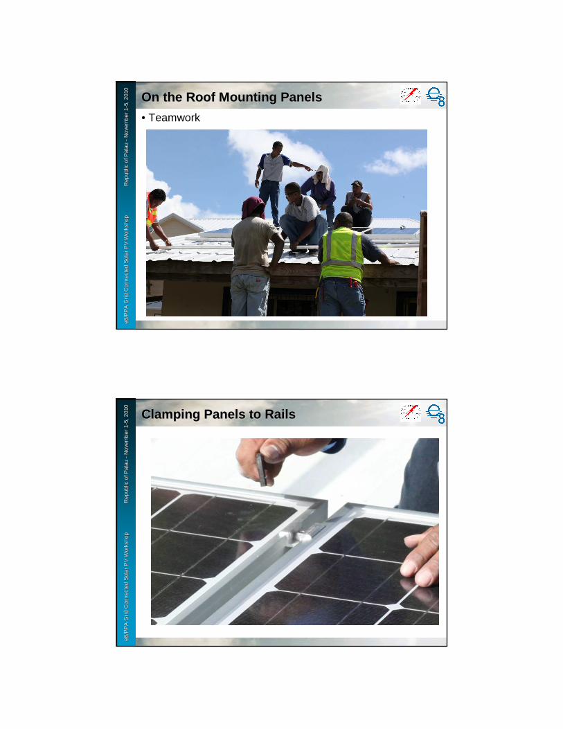
e8 /
PP
A D
SM
Wo
rksh
op
F
iji Is
lan
ds
No
vem
ber
2-6
, 200
9e8
/PP
A G
rid
Con
nect
ed S
olar
PV
Wor
ksho
p
R
epub
le8
/PP
A G
rid
Con
nect
ed S
olar
PV
Wor
ksho
p
R
epub
l ic o
f Pal
au
ic o
f Pal
au --
Nov
embe
r 1
Nov
embe
r 1 --
5, 2
010
5, 2
010
On the Roof Mounting PanelsOn the Roof Mounting Panels
• Teamworke8
/ P
PA
DS
M W
ork
sho
p
Fiji
Isla
nd
s N
ove
mb
er 2
-6, 2
009
e8/P
PA
Gri
d C
onne
cted
Sol
ar P
V W
orks
hop
Rep
ubl
e8/P
PA
Gri
d C
onne
cted
Sol
ar P
V W
orks
hop
Rep
ubl ic
of P
alau
ic
of P
alau
--N
ovem
ber
1N
ovem
ber
1 --5,
201
05,
201
0
Clamping Panels to RailsClamping Panels to Rails

e8 /
PP
A D
SM
Wo
rksh
op
F
iji Is
lan
ds
No
vem
ber
2-6
, 200
9e8
/PP
A G
rid
Con
nect
ed S
olar
PV
Wor
ksho
p
R
epub
le8
/PP
A G
rid
Con
nect
ed S
olar
PV
Wor
ksho
p
R
epub
l ic o
f Pal
au
ic o
f Pal
au --
Nov
embe
r 1
Nov
embe
r 1 --
5, 2
010
5, 2
010
Wiring the String to the InverterWiring the String to the Inverter
• Mounting the junction boxes (for + and − to DC disconnecte8
/ P
PA
DS
M W
ork
sho
p
Fiji
Isla
nd
s N
ove
mb
er 2
-6, 2
009
e8/P
PA
Gri
d C
onne
cted
Sol
ar P
V W
orks
hop
Rep
ubl
e8/P
PA
Gri
d C
onne
cted
Sol
ar P
V W
orks
hop
Rep
ubl ic
of P
alau
ic
of P
alau
--N
ovem
ber
1N
ovem
ber
1 --5,
201
05,
201
0
Wiring the String to the InverterWiring the String to the Inverter
• Wiring to the inverter with + connection in one junction box. A − junction box is at the other end of the string with its wire going around the string to go through the + junction box but with no connection in the box. The −wire goes through the + box just to enter the conduit to the inverter

e8 /
PP
A D
SM
Wo
rksh
op
F
iji Is
lan
ds
No
vem
ber
2-6
, 200
9e8
/PP
A G
rid
Con
nect
ed S
olar
PV
Wor
ksho
p
R
epub
le8
/PP
A G
rid
Con
nect
ed S
olar
PV
Wor
ksho
p
R
epub
l ic o
f Pal
au
ic o
f Pal
au --
Nov
embe
r 1
Nov
embe
r 1 --
5, 2
010
5, 2
010
Mount the Sensor BoxMount the Sensor Box
• The sensor box should be mounted on the same slope as the panels so the solar measurement shows the amount actually falling on the panels. Glue the cell temperature sensor to the back of one panel. Do not cut or extend the temperature sensor wire, it is special wire. The data line goes down the same conduit as the wires to the inverter from the string.
e8 /
PP
A D
SM
Wo
rksh
op
F
iji Is
lan
ds
No
vem
ber
2-6
, 200
9e8
/PP
A G
rid
Con
nect
ed S
olar
PV
Wor
ksho
p
R
epub
le8
/PP
A G
rid
Con
nect
ed S
olar
PV
Wor
ksho
p
R
epub
l ic o
f Pal
au
ic o
f Pal
au --
Nov
embe
r 1
Nov
embe
r 1 --
5, 2
010
5, 2
010 Attach Frame Ground Wires and Tie Up Attach Frame Ground Wires and Tie Up
Wires off the RoofWires off the Roof• Attach ground wire to rails using stainless steel or
copper hardware. Tie up all panel wiring to rails so none touches the roof. Run ground wire through the main conduit.
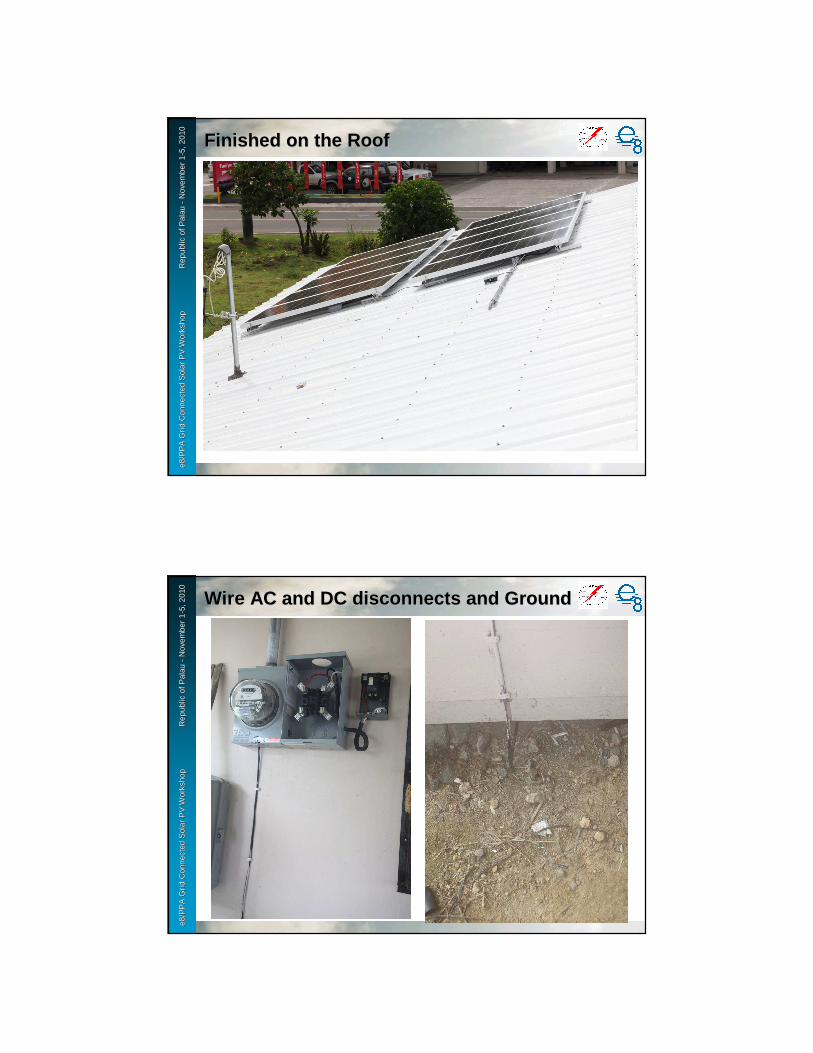
e8 /
PP
A D
SM
Wo
rksh
op
F
iji Is
lan
ds
No
vem
ber
2-6
, 200
9e8
/PP
A G
rid
Con
nect
ed S
olar
PV
Wor
ksho
p
R
epub
le8
/PP
A G
rid
Con
nect
ed S
olar
PV
Wor
ksho
p
R
epub
l ic o
f Pal
au
ic o
f Pal
au --
Nov
embe
r 1
Nov
embe
r 1 --
5, 2
010
5, 2
010
Finished on the RoofFinished on the Roof
e8 /
PP
A D
SM
Wo
rksh
op
F
iji Is
lan
ds
No
vem
ber
2-6
, 200
9e8
/PP
A G
rid
Con
nect
ed S
olar
PV
Wor
ksho
p
R
epub
le8
/PP
A G
rid
Con
nect
ed S
olar
PV
Wor
ksho
p
R
epub
l ic o
f Pal
au
ic o
f Pal
au --
Nov
embe
r 1
Nov
embe
r 1 --
5, 2
010
5, 2
010
Wire AC and DC disconnects and GroundWire AC and DC disconnects and Ground

e8 /
PP
A D
SM
Wo
rksh
op
F
iji Is
lan
ds
No
vem
ber
2-6
, 200
9e8
/PP
A G
rid
Con
nect
ed S
olar
PV
Wor
ksho
p
R
epub
le8
/PP
A G
rid
Con
nect
ed S
olar
PV
Wor
ksho
p
R
epub
l ic o
f Pal
au
ic o
f Pal
au --
Nov
embe
r 1
Nov
embe
r 1 --
5, 2
010
5, 2
010
Connect the Final Panel ConnectionConnect the Final Panel Connection
• Check the voltage and polarity of the DC wires from the string. If the polarity is wrong, disconnect the panel wire on the roof and switch the wires in the disconnect then reconnect and check again. If voltage is wrong, there is an error wiring the panels.
e8 /
PP
A D
SM
Wo
rksh
op
F
iji Is
lan
ds
No
vem
ber
2-6
, 200
9e8
/PP
A G
rid
Con
nect
ed S
olar
PV
Wor
ksho
p
R
epub
le8
/PP
A G
rid
Con
nect
ed S
olar
PV
Wor
ksho
p
R
epub
l ic o
f Pal
au
ic o
f Pal
au --
Nov
embe
r 1
Nov
embe
r 1 --
5, 2
010
5, 2
010
Turn it On and Check for OperationTurn it On and Check for Operation
Turn on AC Disconnect, Turn on DC Disconnect and look for errors as theInverter starts up. In this case, no errors and the system is running

e8 /
PP
A D
SM
Wo
rksh
op
F
iji Is
lan
ds
No
vem
ber
2-6
, 200
9e8
/PP
A G
rid
Con
nect
ed S
olar
PV
Wor
ksho
p
R
epub
le8
/PP
A G
rid
Con
nect
ed S
olar
PV
Wor
ksho
p
R
epub
l ic o
f Pal
au
ic o
f Pal
au --
Nov
embe
r 1
Nov
embe
r 1 --
5, 2
010
5, 2
010
Install and Wire the Data Logging UnitInstall and Wire the Data Logging Unit
e8 /
PP
A D
SM
Wo
rksh
op
F
iji Is
lan
ds
No
vem
ber
2-6
, 200
9e8
/PP
A G
rid
Con
nect
ed S
olar
PV
Wor
ksho
p
R
epub
le8
/PP
A G
rid
Con
nect
ed S
olar
PV
Wor
ksho
p
R
epub
l ic o
f Pal
au
ic o
f Pal
au --
Nov
embe
r 1
Nov
embe
r 1 --
5, 2
010
5, 2
010
Inverter Installation Complete and RunningInverter Installation Complete and Running

1
Day 3Day 3


Grid Connected Solar PV WorkshopPalau
November 1-5,2010
SHS, Mini gridSHS, Mini grid(PV mini grid)(PV mini grid)
e8 /
PP
A D
SM
Wo
rksh
op
F
iji Is
lan
ds
No
vem
ber
2-6
, 200
9e8
/PP
A G
rid
Con
nect
ed S
olar
PV
Wor
ksho
p
R
epub
le8
/PP
A G
rid
Con
nect
ed S
olar
PV
Wor
ksho
p
R
epub
l ic o
f Pal
au
ic o
f Pal
au --
Nov
embe
r 1
Nov
embe
r 1 --
5, 2
010
5, 2
010
2
Type of power systemType of power system
Interconnection to Main Grid: Off, On
Install a renewable energy systemin a small community, sometimescombined with diesel generators.
In case of combined system,it can save diesel fuel consumptionand enhance power supply.
(1) Solar Home System (Capacity: 50W )
(2) Mini grid system (Capacity:10 to 500kW )
(3) Normal grid power system (Capacity: > 500kW )
Install a renewable energy systemin each household separately
This system is applied mainly for a non-electrified region or a rural area.
Install a renewable energy systemto the main grid.
PV
PV
PV
DGDG
M a i n G r i d( > 500kW )
G
Off
On

e8 /
PP
A D
SM
Wo
rksh
op
F
iji Is
lan
ds
No
vem
ber
2-6
, 200
9e8
/PP
A G
rid
Con
nect
ed S
olar
PV
Wor
ksho
p
R
epub
le8
/PP
A G
rid
Con
nect
ed S
olar
PV
Wor
ksho
p
R
epub
l ic o
f Pal
au
ic o
f Pal
au --
Nov
embe
r 1
Nov
embe
r 1 --
5, 2
010
5, 2
010
3
No Title Sub-t.itle Main Grid connection
Suppliedpower
Gen Size(approx.)
Genset Other RNE
Batterysystem
Note
(1) SHS DC SHS Off DC < 1kW No No Yes
AC SHS Off AC < 1kW No No Yes
(2) Mini grid PV Mini grid
Off AC 1 - 50kW No No Yes 50 to 600HouseholdsBattery charge station
PV hybrid systems within mini-grid
Off AC 10 - 500kW Optional (a few hours per day)
Windbiomassmicro-hydroetc.
Optional New components
(3) Grid connected Large PV system & Hybrid system
Grid connected large PV system
On AC > 40kW No No Optional With reliable grid (24H supply)
Grid connected hybrid system
On AC > 100kW Basically No. Optional(a few hours per day)
Windbiomassmicro-hydroetc.
Optional With reliable grid (24H supply)
Off Grid: Solar Home System (SHS)Off Grid: Solar Home System (SHS)
e8 /
PP
A D
SM
Wo
rksh
op
F
iji Is
lan
ds
No
vem
ber
2-6
, 200
9e8
/PP
A G
rid
Con
nect
ed S
olar
PV
Wor
ksho
p
R
epub
le8
/PP
A G
rid
Con
nect
ed S
olar
PV
Wor
ksho
p
R
epub
l ic o
f Pal
au
ic o
f Pal
au --
Nov
embe
r 1
Nov
embe
r 1 --
5, 2
010
5, 2
010
4
Example of SHS (solar home system)Example of SHS (solar home system)
Solar array
Solar arraySolar array
Solar array
Controller
Light
Storage battery
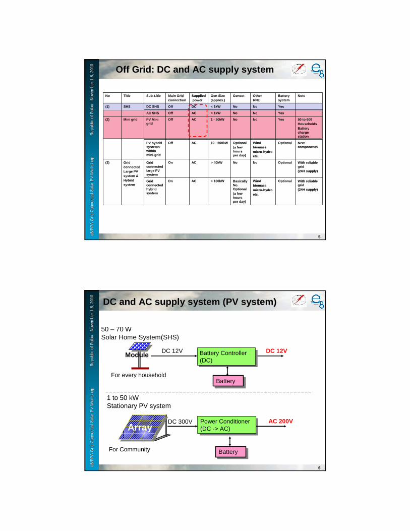
e8 /
PP
A D
SM
Wo
rksh
op
F
iji Is
lan
ds
No
vem
ber
2-6
, 200
9e8
/PP
A G
rid
Con
nect
ed S
olar
PV
Wor
ksho
p
R
epub
le8
/PP
A G
rid
Con
nect
ed S
olar
PV
Wor
ksho
p
R
epub
l ic o
f Pal
au
ic o
f Pal
au --
Nov
embe
r 1
Nov
embe
r 1 --
5, 2
010
5, 2
010
5
No Title Sub-t.itle Main Grid connection
Suppliedpower
Gen Size(approx.)
Genset Other RNE
Batterysystem
Note
(1) SHS DC SHS Off DC < 1kW No No Yes
AC SHS Off AC < 1kW No No Yes
(2) Mini grid PV Mini grid
Off AC 1 - 50kW No No Yes 50 to 600HouseholdsBattery charge station
PV hybrid systems within mini-grid
Off AC 10 - 500kW Optional (a few hours per day)
Windbiomassmicro-hydroetc.
Optional New components
(3) Grid connected Large PV system & Hybrid system
Grid connected large PV system
On AC > 40kW No No Optional With reliable grid (24H supply)
Grid connected hybrid system
On AC > 100kW Basically No. Optional(a few hours per day)
Windbiomassmicro-hydroetc.
Optional With reliable grid (24H supply)
Off Grid: DC and AC supply system Off Grid: DC and AC supply system
e8 /
PP
A D
SM
Wo
rksh
op
F
iji Is
lan
ds
No
vem
ber
2-6
, 200
9e8
/PP
A G
rid
Con
nect
ed S
olar
PV
Wor
ksho
p
R
epub
le8
/PP
A G
rid
Con
nect
ed S
olar
PV
Wor
ksho
p
R
epub
l ic o
f Pal
au
ic o
f Pal
au --
Nov
embe
r 1
Nov
embe
r 1 --
5, 2
010
5, 2
010
6
DC and AC supply system (PV system)DC and AC supply system (PV system)
50 – 70 WSolar Home System(SHS)
1 to 50 kWStationary PV system
Power Conditioner(DC -> AC)
Power Conditioner(DC -> AC)
AC 200VDC 300V
BatteryBatteryFor Community
Array
Battery Controller(DC)
Battery Controller(DC)
DC 12VDC 12V
BatteryBatteryFor every household
Module
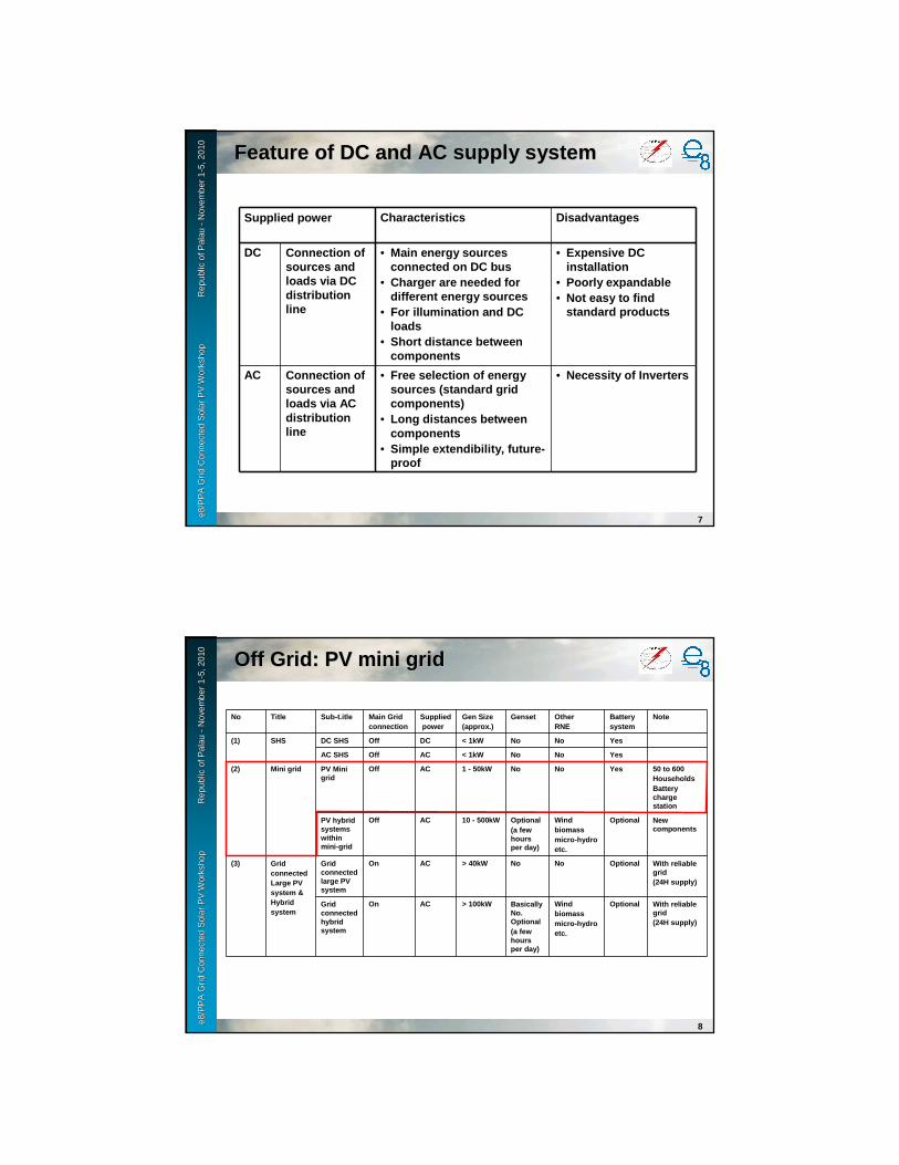
e8 /
PP
A D
SM
Wo
rksh
op
F
iji Is
lan
ds
No
vem
ber
2-6
, 200
9e8
/PP
A G
rid
Con
nect
ed S
olar
PV
Wor
ksho
p
R
epub
le8
/PP
A G
rid
Con
nect
ed S
olar
PV
Wor
ksho
p
R
epub
l ic o
f Pal
au
ic o
f Pal
au --
Nov
embe
r 1
Nov
embe
r 1 --
5, 2
010
5, 2
010
7
Feature of DC and AC supply systemFeature of DC and AC supply system
Supplied power Characteristics Disadvantages
DC Connection of sources and loads via DC distribution line
• Main energy sources connected on DC bus
• Charger are needed for different energy sources
• For illumination and DC loads
• Short distance between components
• Expensive DC installation
• Poorly expandable• Not easy to find
standard products
AC Connection of sources and loads via AC distribution line
• Free selection of energy sources (standard grid components)
• Long distances between components
• Simple extendibility, future-proof
• Necessity of Inverters
e8 /
PP
A D
SM
Wo
rksh
op
F
iji Is
lan
ds
No
vem
ber
2-6
, 200
9e8
/PP
A G
rid
Con
nect
ed S
olar
PV
Wor
ksho
p
R
epub
le8
/PP
A G
rid
Con
nect
ed S
olar
PV
Wor
ksho
p
R
epub
l ic o
f Pal
au
ic o
f Pal
au --
Nov
embe
r 1
Nov
embe
r 1 --
5, 2
010
5, 2
010
8
No Title Sub-t.itle Main Grid connection
Suppliedpower
Gen Size(approx.)
Genset Other RNE
Batterysystem
Note
(1) SHS DC SHS Off DC < 1kW No No Yes
AC SHS Off AC < 1kW No No Yes
(2) Mini grid PV Mini grid
Off AC 1 - 50kW No No Yes 50 to 600HouseholdsBattery charge station
PV hybrid systems within mini-grid
Off AC 10 - 500kW Optional (a few hours per day)
Windbiomassmicro-hydroetc.
Optional New components
(3) Grid connected Large PV system & Hybrid system
Grid connected large PV system
On AC > 40kW No No Optional With reliable grid (24H supply)
Grid connected hybrid system
On AC > 100kW Basically No. Optional(a few hours per day)
Windbiomassmicro-hydroetc.
Optional With reliable grid (24H supply)
Off Grid: PV mini grid Off Grid: PV mini grid
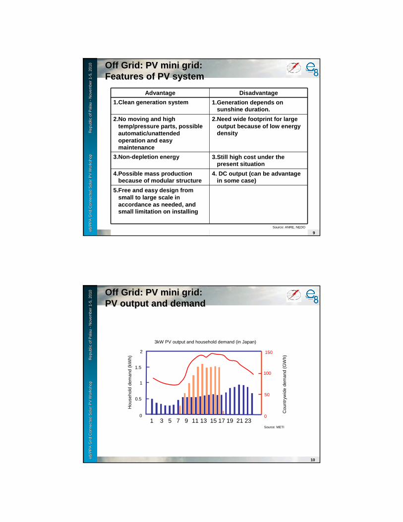
e8 /
PP
A D
SM
Wo
rksh
op
F
iji Is
lan
ds
No
vem
ber
2-6
, 200
9e8
/PP
A G
rid
Con
nect
ed S
olar
PV
Wor
ksho
p
R
epub
le8
/PP
A G
rid
Con
nect
ed S
olar
PV
Wor
ksho
p
R
epub
l ic o
f Pal
au
ic o
f Pal
au --
Nov
embe
r 1
Nov
embe
r 1 --
5, 2
010
5, 2
010
9
Advantage Disadvantage
1.Clean generation system 1.Generation depends on sunshine duration.
2.No moving and high temp/pressure parts, possible automatic/unattended operation and easy maintenance
2.Need wide footprint for large output because of low energy density
3.Non-depletion energy 3.Still high cost under the present situation
4.Possible mass production because of modular structure
4. DC output (can be advantage in some case)
5.Free and easy design from small to large scale in accordance as needed, and small limitation on installing
Source: ANRE, NEDO
Off Grid: PV mini grid:Off Grid: PV mini grid:Features of PV systemFeatures of PV system
e8 /
PP
A D
SM
Wo
rksh
op
F
iji Is
lan
ds
No
vem
ber
2-6
, 200
9e8
/PP
A G
rid
Con
nect
ed S
olar
PV
Wor
ksho
p
R
epub
le8
/PP
A G
rid
Con
nect
ed S
olar
PV
Wor
ksho
p
R
epub
l ic o
f Pal
au
ic o
f Pal
au --
Nov
embe
r 1
Nov
embe
r 1 --
5, 2
010
5, 2
010
10
Off Grid: PV mini grid:Off Grid: PV mini grid:PV output and demand PV output and demand
1 3 5 7 9 11 13 15 17 19 21 23Source: METI
2
1.5
1
0.5
0
150
100
50
0
Hou
seho
ld d
eman
d (k
Wh)
Cou
ntry
wid
e de
man
d (G
Wh)
3kW PV output and household demand (in Japan)
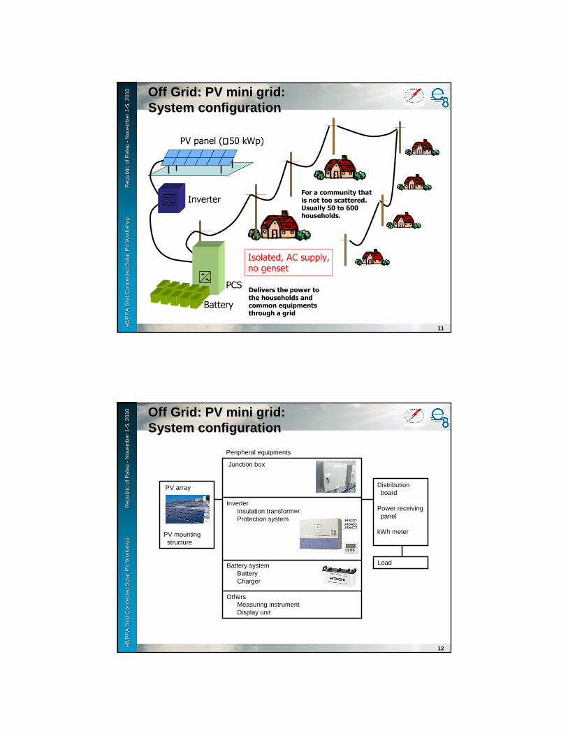
e8 /
PP
A D
SM
Wo
rksh
op
F
iji Is
lan
ds
No
vem
ber
2-6
, 200
9e8
/PP
A G
rid
Con
nect
ed S
olar
PV
Wor
ksho
p
R
epub
le8
/PP
A G
rid
Con
nect
ed S
olar
PV
Wor
ksho
p
R
epub
l ic o
f Pal
au
ic o
f Pal
au --
Nov
embe
r 1
Nov
embe
r 1 --
5, 2
010
5, 2
010
11
PV panel (≅≅≅≅ 50 kWp)
Off Grid: PV mini grid: Off Grid: PV mini grid: System configurationSystem configuration
Inverter
Battery
PCS
For a community that is not too scattered. Usually 50 to 600 households.
Delivers the power to the households and common equipments through a grid
Isolated, AC supply, no genset
e8 /
PP
A D
SM
Wo
rksh
op
F
iji Is
lan
ds
No
vem
ber
2-6
, 200
9e8
/PP
A G
rid
Con
nect
ed S
olar
PV
Wor
ksho
p
R
epub
le8
/PP
A G
rid
Con
nect
ed S
olar
PV
Wor
ksho
p
R
epub
l ic o
f Pal
au
ic o
f Pal
au --
Nov
embe
r 1
Nov
embe
r 1 --
5, 2
010
5, 2
010
12
Off Grid: PV mini grid: Off Grid: PV mini grid: System configurationSystem configuration
PV array
PV mounting structure
Junction box
InverterInsulation transformerProtection system
Battery systemBatteryCharger
OthersMeasuring instrumentDisplay unit
Distribution board
Power receiving panel
kWh meter
Load
Peripheral equipments

e8 /
PP
A D
SM
Wo
rksh
op
F
iji Is
lan
ds
No
vem
ber
2-6
, 200
9e8
/PP
A G
rid
Con
nect
ed S
olar
PV
Wor
ksho
p
R
epub
le8
/PP
A G
rid
Con
nect
ed S
olar
PV
Wor
ksho
p
R
epub
l ic o
f Pal
au
ic o
f Pal
au --
Nov
embe
r 1
Nov
embe
r 1 --
5, 2
010
5, 2
010
13
Off Grid: PV mini grid: Off Grid: PV mini grid: ExamplesExamples
Installed in 2003 at Suohourima, Qinghai, China by GTZ
70 km from the next electricity line
Between 300 and 400 households
Old Diesel generator set is no longer in operation.
Electricity is delivered according to energy availability (not for 24/24 hours)
Source: GTZ-ZSW
e8 /
PP
A D
SM
Wo
rksh
op
F
iji Is
lan
ds
No
vem
ber
2-6
, 200
9e8
/PP
A G
rid
Con
nect
ed S
olar
PV
Wor
ksho
p
R
epub
le8
/PP
A G
rid
Con
nect
ed S
olar
PV
Wor
ksho
p
R
epub
l ic o
f Pal
au
ic o
f Pal
au --
Nov
embe
r 1
Nov
embe
r 1 --
5, 2
010
5, 2
010
14
Off Grid: PV mini grid: Off Grid: PV mini grid: ExamplesExamples
PV-generator
40 kW, 26 parallel strings with 18 modules, 85 W per module, manufacturer Qinghai Gaofai, cells from Astropower, US
Chargecontroller
13 channels, μC-controlled, sub arrays are switched off at the end of charge voltage of the battery, manufacturer Hefei Sunlight Power
Battery Sealed (AGM) lead acid battery, cells 2 V/1300 Ah, 3 parallel strings with 110 cells, 858 kWh, manufacturer Enersys Huada Solar
Inverters PWM with transformer and μC-control, 220 VDC/220 VAC, 1 inverter with 16 kW, 1 inverter with 24 kW, manufacturer Hefei Sunlight Power
ACDistribution
2 isolated and not grounded single phase grids supply different parts of the township. The single households have electronic energy Meters
Households All electrified households have electric light (fluorescent lamps (9W) or incandescent lamps (40W)), 90 % of the households have colour TV + satellite receiver + DVD player, and chest freezer to store meat, more and more households have electric heating blankets and pillows, some have washing machines (for external hot water supply)
Source: GTZ-ZSW

e8 /
PP
A D
SM
Wo
rksh
op
F
iji Is
lan
ds
No
vem
ber
2-6
, 200
9e8
/PP
A G
rid
Con
nect
ed S
olar
PV
Wor
ksho
p
R
epub
le8
/PP
A G
rid
Con
nect
ed S
olar
PV
Wor
ksho
p
R
epub
l ic o
f Pal
au
ic o
f Pal
au --
Nov
embe
r 1
Nov
embe
r 1 --
5, 2
010
5, 2
010
15
Off Grid: PV mini grid: Off Grid: PV mini grid: ExamplesExamples
Source: GTZ-ZSW
e8 /
PP
A D
SM
Wo
rksh
op
F
iji Is
lan
ds
No
vem
ber
2-6
, 200
9e8
/PP
A G
rid
Con
nect
ed S
olar
PV
Wor
ksho
p
R
epub
le8
/PP
A G
rid
Con
nect
ed S
olar
PV
Wor
ksho
p
R
epub
l ic o
f Pal
au
ic o
f Pal
au --
Nov
embe
r 1
Nov
embe
r 1 --
5, 2
010
5, 2
010
16
Off Grid: PV mini grid:Off Grid: PV mini grid:Design procedureDesign procedure
• Significance• Concept• Feasibility study
– Generation– Distribution– Demand forecast and dispatching– Environmental assessment– Economical evaluation
• Design – System configuration – Design– Regulation– Specification of components– How to select– Installation
• O&M

e8 /
PP
A D
SM
Wo
rksh
op
F
iji Is
lan
ds
No
vem
ber
2-6
, 200
9e8
/PP
A G
rid
Con
nect
ed S
olar
PV
Wor
ksho
p
R
epub
le8
/PP
A G
rid
Con
nect
ed S
olar
PV
Wor
ksho
p
R
epub
l ic o
f Pal
au
ic o
f Pal
au --
Nov
embe
r 1
Nov
embe
r 1 --
5, 2
010
5, 2
010
17
Off Grid: PV mini grid: Off Grid: PV mini grid: Planning & designPlanning & design
Survey of various REN
Concept design of the system
Investigation of target site
Determination of equipment spec.
Estimate project cost
Determine operation patternEstimate maintenance cost
Estimate total running cost
Analyze cost/benefit
Effect on environmental protection
Effect on energy conservation
Implementation
System, equip. spec., supplier, capacity, supply characteristics, reliability, cost and so on.
Demand characteristics, energy cost, electricity tariff
REN main unit, inverter, grid connection, battery, env. measure
Generation cost, distribution cost, cash flow
Estimate supplied power and energy
e8 /
PP
A D
SM
Wo
rksh
op
F
iji Is
lan
ds
No
vem
ber
2-6
, 200
9e8
/PP
A G
rid
Con
nect
ed S
olar
PV
Wor
ksho
p
R
epub
le8
/PP
A G
rid
Con
nect
ed S
olar
PV
Wor
ksho
p
R
epub
l ic o
f Pal
au
ic o
f Pal
au --
Nov
embe
r 1
Nov
embe
r 1 --
5, 2
010
5, 2
010
18
Off Grid: PV mini grid: Off Grid: PV mini grid: Check list on planning (1)Check list on planning (1)
• Concept and purpose– For what?
� Purposed should be shared among concerned parties.
– Where? � In existing facility or not? Exact location.
– What load?� Characteristics and size of load. Enough space
for installed equipment?– Which system?
� Isolated or grid-connected? With battery or not?– When and how much?
� Construction schedule and cost. Can it be available?

e8 /
PP
A D
SM
Wo
rksh
op
F
iji Is
lan
ds
No
vem
ber
2-6
, 200
9e8
/PP
A G
rid
Con
nect
ed S
olar
PV
Wor
ksho
p
R
epub
le8
/PP
A G
rid
Con
nect
ed S
olar
PV
Wor
ksho
p
R
epub
l ic o
f Pal
au
ic o
f Pal
au --
Nov
embe
r 1
Nov
embe
r 1 --
5, 2
010
5, 2
010
19
Off Grid: PV mini grid: Off Grid: PV mini grid: Check list on planning (2)Check list on planning (2)
• Project team– Establish team and assign project manager– How to select the designer?– What is bidding strategy of construction work?– How can we maintain and manage the system?
e8 /
PP
A D
SM
Wo
rksh
op
F
iji Is
lan
ds
No
vem
ber
2-6
, 200
9e8
/PP
A G
rid
Con
nect
ed S
olar
PV
Wor
ksho
p
R
epub
le8
/PP
A G
rid
Con
nect
ed S
olar
PV
Wor
ksho
p
R
epub
l ic o
f Pal
au
ic o
f Pal
au --
Nov
embe
r 1
Nov
embe
r 1 --
5, 2
010
5, 2
010
20
Off Grid: PV mini grid: Off Grid: PV mini grid: Check list on planning (3)Check list on planning (3)
• Site survey– Ambient environment
� Any obstacles to receive sunlight? � Shadow of building, tree, mountain, stack, utility pole, steel
tower, sign board and so on.� Effect of fallen leaves and sand dust, snow cover (depth and
frequency)� Salt and/or lightning damage, wind condition – collect all
the possible obstacles– Installed site
� Shape, width, direction, drainage, condition of foundation, volume of construction work, carry-in route, Waterproof of the building, effect on landscape
– Electrical facility� Existing diagram and plot plan, space availability, wiring
route and space carry-in route
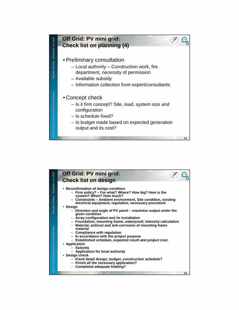
e8 /
PP
A D
SM
Wo
rksh
op
F
iji Is
lan
ds
No
vem
ber
2-6
, 200
9e8
/PP
A G
rid
Con
nect
ed S
olar
PV
Wor
ksho
p
R
epub
le8
/PP
A G
rid
Con
nect
ed S
olar
PV
Wor
ksho
p
R
epub
l ic o
f Pal
au
ic o
f Pal
au --
Nov
embe
r 1
Nov
embe
r 1 --
5, 2
010
5, 2
010
21
Off Grid: PV mini grid: Off Grid: PV mini grid: Check list on planning (4)Check list on planning (4)
• Preliminary consultation– Local authority – Construction work, fire
department, necessity of permission– Available subsidy– Information collection from expert/consultants
• Concept check– Is it firm concept? Site, load, system size and
configuration– Is schedule fixed?– Is budget made based on expected generation
output and its cost?
e8 /
PP
A D
SM
Wo
rksh
op
F
iji Is
lan
ds
No
vem
ber
2-6
, 200
9e8
/PP
A G
rid
Con
nect
ed S
olar
PV
Wor
ksho
p
R
epub
le8
/PP
A G
rid
Con
nect
ed S
olar
PV
Wor
ksho
p
R
epub
l ic o
f Pal
au
ic o
f Pal
au --
Nov
embe
r 1
Nov
embe
r 1 --
5, 2
010
5, 2
010
22
Off Grid: PV mini grid: Off Grid: PV mini grid: Check list on designCheck list on design• Reconfirmation of design condition
– Firm policy? – For what? Where? How big? How is the system? When? How much?
– Constraints – Ambient environment, Site condition, e xisting electrical equipment, regulation, necessary procedu re
• Design– Direction and angle of PV panel – maximize output un der the
given condition– Array configuration and its installation– Foundation, mounting frame, waterproof, intensity c alculation– Material, antirust and anti-corrosion of mounting f rame
material– Compliance with regulation– In accordance with the project purpose– Established schedule, expected result and project c ost.
• Application– Subsidy– Application for local authority
• Design check– Fixed detail design, budget, construction schedule?– Finish all the necessary application?– Completed adequate bidding?
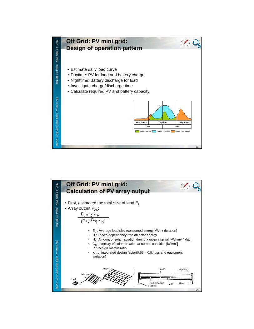
e8 /
PP
A D
SM
Wo
rksh
op
F
iji Is
lan
ds
No
vem
ber
2-6
, 200
9e8
/PP
A G
rid
Con
nect
ed S
olar
PV
Wor
ksho
p
R
epub
le8
/PP
A G
rid
Con
nect
ed S
olar
PV
Wor
ksho
p
R
epub
l ic o
f Pal
au
ic o
f Pal
au --
Nov
embe
r 1
Nov
embe
r 1 --
5, 2
010
5, 2
010
23
Off Grid: PV mini grid: Off Grid: PV mini grid: Design of operation patternDesign of operation pattern
• Estimate daily load curve• Daytime: PV for load and battery charge• Nighttime: Battery discharge for load• Investigate charge/discharge time• Calculate required PV and battery capacity
Wee hours Daytime Nighttime
PMAM
Supply from PV Charge to battery Supply from battery
e8 /
PP
A D
SM
Wo
rksh
op
F
iji Is
lan
ds
No
vem
ber
2-6
, 200
9e8
/PP
A G
rid
Con
nect
ed S
olar
PV
Wor
ksho
p
R
epub
le8
/PP
A G
rid
Con
nect
ed S
olar
PV
Wor
ksho
p
R
epub
l ic o
f Pal
au
ic o
f Pal
au --
Nov
embe
r 1
Nov
embe
r 1 --
5, 2
010
5, 2
010
24
• First, estimated the total size of load EL
• Array output PAS:EL * D * R(HA / GS) * K
� EL : Average load size (consumed energy kWh / duration)� D : Load’s dependency rate on solar energy� HA: Amount of solar radiation during a given interval [kWh/m2 * day] � GS: Intensity of solar radiation at normal condition [kW/m2]� R : Design margin ratio� K : of integrated design factor(0.65 – 0.8, loss and equipment
variation)
Off Grid: PV mini grid: Off Grid: PV mini grid: Calculation of PV array outputCalculation of PV array output
Cell
Module
Array
Backside film Cell
Packing
Filling
Glass
Bracket
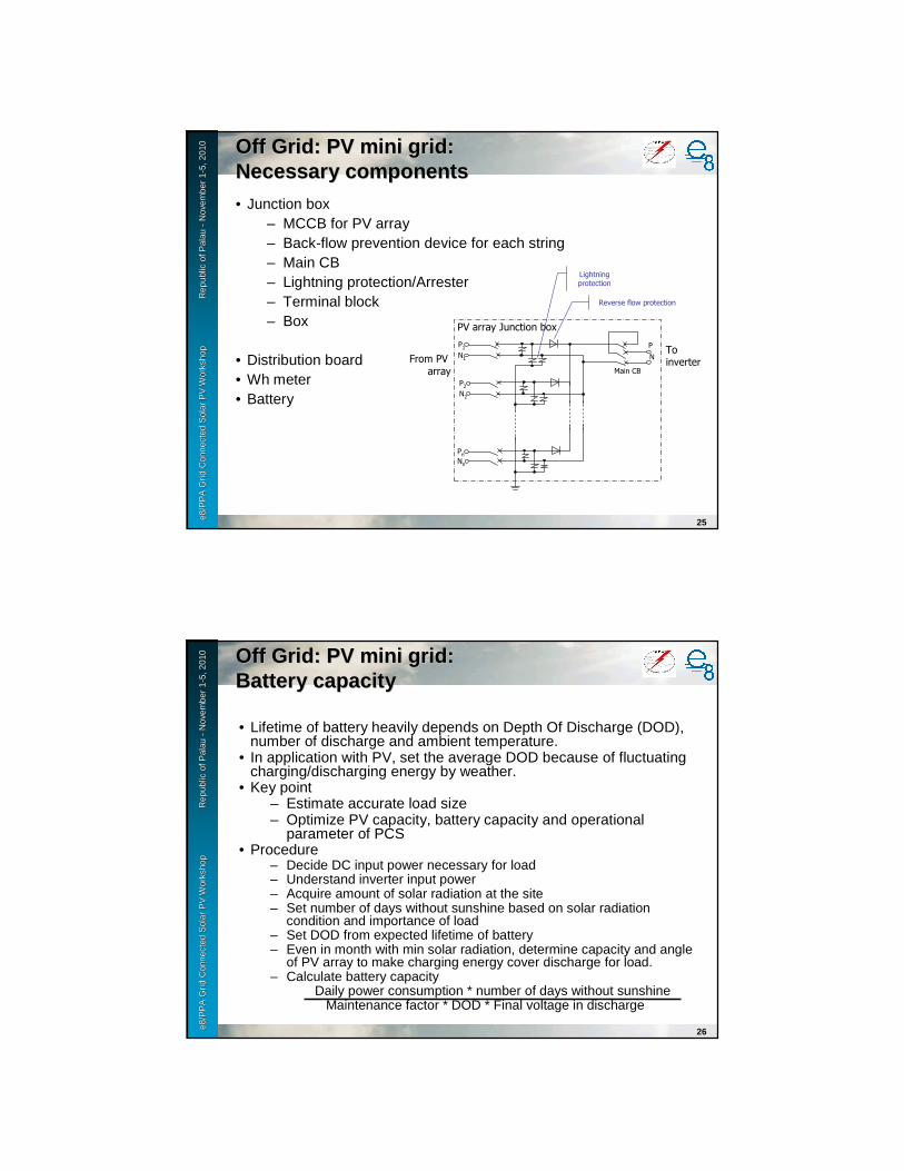
e8 /
PP
A D
SM
Wo
rksh
op
F
iji Is
lan
ds
No
vem
ber
2-6
, 200
9e8
/PP
A G
rid
Con
nect
ed S
olar
PV
Wor
ksho
p
R
epub
le8
/PP
A G
rid
Con
nect
ed S
olar
PV
Wor
ksho
p
R
epub
l ic o
f Pal
au
ic o
f Pal
au --
Nov
embe
r 1
Nov
embe
r 1 --
5, 2
010
5, 2
010
25
Off Grid: PV mini grid: Off Grid: PV mini grid: Necessary componentsNecessary components• Junction box
– MCCB for PV array– Back-flow prevention device for each string– Main CB– Lightning protection/Arrester– Terminal block– Box
• Distribution board• Wh meter• Battery
From PV array
PV array Junction box
P1N1
P2N2
PnNn
N
PTo inverter
Reverse flow protection
Main CB
Lightning protection
e8 /
PP
A D
SM
Wo
rksh
op
F
iji Is
lan
ds
No
vem
ber
2-6
, 200
9e8
/PP
A G
rid
Con
nect
ed S
olar
PV
Wor
ksho
p
R
epub
le8
/PP
A G
rid
Con
nect
ed S
olar
PV
Wor
ksho
p
R
epub
l ic o
f Pal
au
ic o
f Pal
au --
Nov
embe
r 1
Nov
embe
r 1 --
5, 2
010
5, 2
010
26
Off Grid: PV mini grid: Off Grid: PV mini grid: Battery capacityBattery capacity
• Lifetime of battery heavily depends on Depth Of Discharge (DOD),number of discharge and ambient temperature.
• In application with PV, set the average DOD because of fluctuating charging/discharging energy by weather.
• Key point– Estimate accurate load size– Optimize PV capacity, battery capacity and operational
parameter of PCS• Procedure
– Decide DC input power necessary for load– Understand inverter input power– Acquire amount of solar radiation at the site– Set number of days without sunshine based on solar radiation
condition and importance of load– Set DOD from expected lifetime of battery– Even in month with min solar radiation, determine capacity and angle
of PV array to make charging energy cover discharge for load.– Calculate battery capacity
Daily power consumption * number of days without sunshineMaintenance factor * DOD * Final voltage in discharge

e8 /
PP
A D
SM
Wo
rksh
op
F
iji Is
lan
ds
No
vem
ber
2-6
, 200
9e8
/PP
A G
rid
Con
nect
ed S
olar
PV
Wor
ksho
p
R
epub
le8
/PP
A G
rid
Con
nect
ed S
olar
PV
Wor
ksho
p
R
epub
l ic o
f Pal
au
ic o
f Pal
au --
Nov
embe
r 1
Nov
embe
r 1 --
5, 2
010
5, 2
010
27
Off Grid: PV mini grid: Off Grid: PV mini grid: Operation & maintenanceOperation & maintenance
• Load forecasting is most important.• Aim to full utilize PV power.• Reserve battery energy for emergency case.• Adjust charge/discharge energy in accordance with varying load.
Wee hours Daytime Nighttime
PMAM
Supply from PV Charge to battery Supply from battery
e8 /
PP
A D
SM
Wo
rksh
op
F
iji Is
lan
ds
No
vem
ber
2-6
, 200
9e8
/PP
A G
rid
Con
nect
ed S
olar
PV
Wor
ksho
p
R
epub
le8
/PP
A G
rid
Con
nect
ed S
olar
PV
Wor
ksho
p
R
epub
l ic o
f Pal
au
ic o
f Pal
au --
Nov
embe
r 1
Nov
embe
r 1 --
5, 2
010
5, 2
010
28
Off Grid: PV mini grid: Off Grid: PV mini grid: Battery charging station (optional)Battery charging station (optional)
BCS at suburb of Phnom Penh, Cambodia

e8 /
PP
A D
SM
Wo
rksh
op
F
iji Is
lan
ds
No
vem
ber
2-6
, 200
9e8
/PP
A G
rid
Con
nect
ed S
olar
PV
Wor
ksho
p
R
epub
le8
/PP
A G
rid
Con
nect
ed S
olar
PV
Wor
ksho
p
R
epub
l ic o
f Pal
au
ic o
f Pal
au --
Nov
embe
r 1
Nov
embe
r 1 --
5, 2
010
5, 2
010
29
Off Grid: PV mini grid: Off Grid: PV mini grid: Battery charging station (optional)Battery charging station (optional)
A fully charged battery provides lighting for a week
Kanchanaburi Province, Thailand: 1992-1997
Budget: 316 million yen
The Sunlight made Nighttime Pleasant !
Battery-Charging Station
Source: NEDO
e8 /
PP
A D
SM
Wo
rksh
op
F
iji Is
lan
ds
No
vem
ber
2-6
, 200
9e8
/PP
A G
rid
Con
nect
ed S
olar
PV
Wor
ksho
p
R
epub
le8
/PP
A G
rid
Con
nect
ed S
olar
PV
Wor
ksho
p
R
epub
l ic o
f Pal
au
ic o
f Pal
au --
Nov
embe
r 1
Nov
embe
r 1 --
5, 2
010
5, 2
010
30
Battery-Charging Station
Using a charged battery at home
Off Grid: PV mini grid: Off Grid: PV mini grid: Battery charging station (optional)Battery charging station (optional)
Source: NEDO


Grid Connected Solar PV WorkshopPalau
November 1-5,2010
Mini gridMini grid(PV hybrid systems within mini grid)(PV hybrid systems within mini grid)
e8 /
PP
A D
SM
Wo
rksh
op
F
iji Is
lan
ds
No
vem
ber
2-6
, 200
9e8
/PP
A G
rid
Con
nect
ed S
olar
PV
Wor
ksho
p
R
epub
le8
/PP
A G
rid
Con
nect
ed S
olar
PV
Wor
ksho
p
R
epub
l ic o
f Pal
au
ic o
f Pal
au --
Nov
embe
r 1
Nov
embe
r 1 --
5, 2
010
5, 2
010
2
No Title Sub-t.itle Main Grid connection
Suppliedpower
Gen Size(approx.)
Genset Other RNE
Batterysystem
Note
(1) SHS DC SHS Off DC < 1kW No No Yes
AC SHS Off AC < 1kW No No Yes
(2) Mini grid PV Mini grid
Off AC 1 - 50kW No No Yes 50 to 600HouseholdsBattery charge station
PV hybrid systems within mini-grid
Off AC 10 - 500kW Optional (a few hours per day)
Windbiomassmicro-hydroetc.
Optional New components
(3) Grid connected Large PV system & Hybrid system
Grid connected large PV system
On AC > 40kW No No Optional With reliable grid (24H supply)
Grid connected hybrid system
On AC > 100kW Basically No. Optional(a few hours per day)
Windbiomassmicro-hydroetc.
Optional With reliable grid (24H supply)
Off Grid: PV mini grid Off Grid: PV mini grid
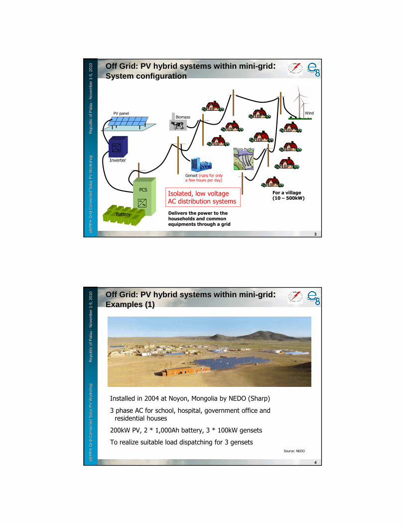
e8 /
PP
A D
SM
Wo
rksh
op
F
iji Is
lan
ds
No
vem
ber
2-6
, 200
9e8
/PP
A G
rid
Con
nect
ed S
olar
PV
Wor
ksho
p
R
epub
le8
/PP
A G
rid
Con
nect
ed S
olar
PV
Wor
ksho
p
R
epub
l ic o
f Pal
au
ic o
f Pal
au --
Nov
embe
r 1
Nov
embe
r 1 --
5, 2
010
5, 2
010
3
Off Grid: PV hybrid systems within mini-grid:System configuration
PV panel
Inverter
Battery
PCSFor a village (10 – 500kW)
Delivers the power to the households and common equipments through a grid
Isolated, low voltage AC distribution systems
Biomass Wind
Micro-hydro
Genset (runs for only a few hours per day)
e8 /
PP
A D
SM
Wo
rksh
op
F
iji Is
lan
ds
No
vem
ber
2-6
, 200
9e8
/PP
A G
rid
Con
nect
ed S
olar
PV
Wor
ksho
p
R
epub
le8
/PP
A G
rid
Con
nect
ed S
olar
PV
Wor
ksho
p
R
epub
l ic o
f Pal
au
ic o
f Pal
au --
Nov
embe
r 1
Nov
embe
r 1 --
5, 2
010
5, 2
010
4
Off Grid: PV hybrid systems within miniOff Grid: PV hybrid systems within mini--gridgrid: : Examples (1)Examples (1)
Installed in 2004 at Noyon, Mongolia by NEDO (Sharp)
3 phase AC for school, hospital, government office and residential houses
200kW PV, 2 * 1,000Ah battery, 3 * 100kW gensets
To realize suitable load dispatching for 3 gensetsSource: NEDO
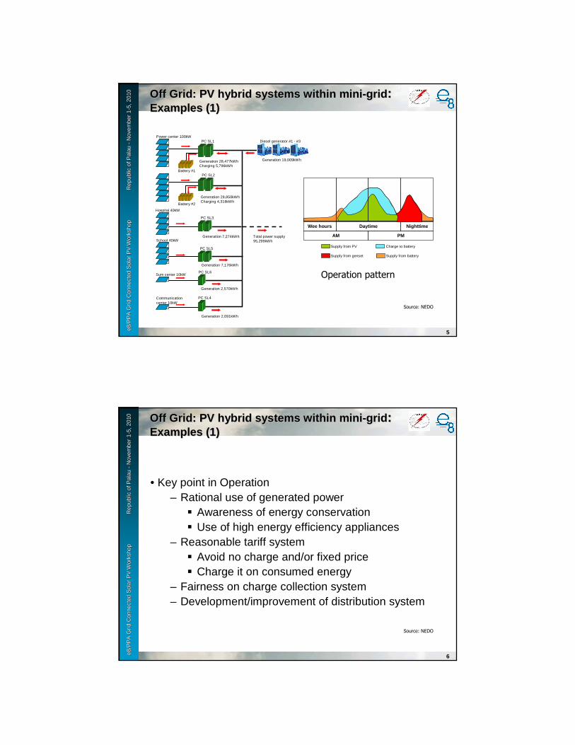
e8 /
PP
A D
SM
Wo
rksh
op
F
iji Is
lan
ds
No
vem
ber
2-6
, 200
9e8
/PP
A G
rid
Con
nect
ed S
olar
PV
Wor
ksho
p
R
epub
le8
/PP
A G
rid
Con
nect
ed S
olar
PV
Wor
ksho
p
R
epub
l ic o
f Pal
au
ic o
f Pal
au --
Nov
embe
r 1
Nov
embe
r 1 --
5, 2
010
5, 2
010
5
Off Grid: PV hybrid systems within miniOff Grid: PV hybrid systems within mini--gridgrid: : Examples (1)Examples (1)
Operation pattern
Wee hours Daytime Nighttime
PMAM
Supply from PV Charge to battery
Supply from batterySupply from genset
Source: NEDO
Power center 100kW
Hospital 40kW
School 40kW
Sum center 10kW
Communicationcenter 10kW
Battery #1
Battery #2
PC SL1
PC SL2
PC SL3
PC SL5
PC SL6
PC SL4
Generation 28,477kWhCharging 5,796kWh
Generation 28,850kWhCharging 4,318kWh
Generation 7,274kWh
Generation 7,176kWh
Generation 2,570kWh
Generation 2,091kWh
Total power supply95,299kWh
Diesel generator #1 - #3
Generation 19,009kWh
e8 /
PP
A D
SM
Wo
rksh
op
F
iji Is
lan
ds
No
vem
ber
2-6
, 200
9e8
/PP
A G
rid
Con
nect
ed S
olar
PV
Wor
ksho
p
R
epub
le8
/PP
A G
rid
Con
nect
ed S
olar
PV
Wor
ksho
p
R
epub
l ic o
f Pal
au
ic o
f Pal
au --
Nov
embe
r 1
Nov
embe
r 1 --
5, 2
010
5, 2
010
6
Off Grid: PV hybrid systems within miniOff Grid: PV hybrid systems within mini--gridgrid: : Examples (1)Examples (1)
• Key point in Operation– Rational use of generated power
� Awareness of energy conservation� Use of high energy efficiency appliances
– Reasonable tariff system� Avoid no charge and/or fixed price� Charge it on consumed energy
– Fairness on charge collection system– Development/improvement of distribution system
Source: NEDO
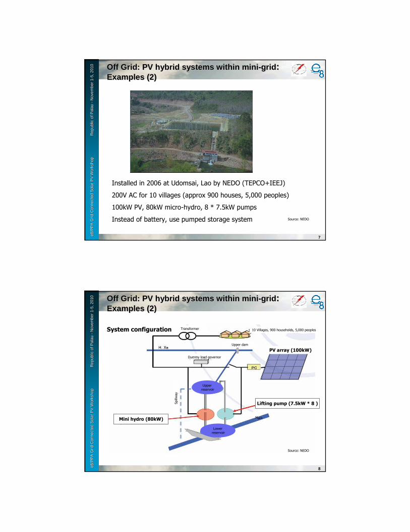
e8 /
PP
A D
SM
Wo
rksh
op
F
iji Is
lan
ds
No
vem
ber
2-6
, 200
9e8
/PP
A G
rid
Con
nect
ed S
olar
PV
Wor
ksho
p
R
epub
le8
/PP
A G
rid
Con
nect
ed S
olar
PV
Wor
ksho
p
R
epub
l ic o
f Pal
au
ic o
f Pal
au --
Nov
embe
r 1
Nov
embe
r 1 --
5, 2
010
5, 2
010
7
Off Grid: PV hybrid systems within miniOff Grid: PV hybrid systems within mini--gridgrid: : Examples (2)Examples (2)
Installed in 2006 at Udomsai, Lao by NEDO (TEPCO+IEEJ)
200V AC for 10 villages (approx 900 houses, 5,000 peoples)
100kW PV, 80kW micro-hydro, 8 * 7.5kW pumps
Instead of battery, use pumped storage system Source: NEDO
e8 /
PP
A D
SM
Wo
rksh
op
F
iji Is
lan
ds
No
vem
ber
2-6
, 200
9e8
/PP
A G
rid
Con
nect
ed S
olar
PV
Wor
ksho
p
R
epub
le8
/PP
A G
rid
Con
nect
ed S
olar
PV
Wor
ksho
p
R
epub
l ic o
f Pal
au
ic o
f Pal
au --
Nov
embe
r 1
Nov
embe
r 1 --
5, 2
010
5, 2
010
8
Off Grid: PV hybrid systems within miniOff Grid: PV hybrid systems within mini--gridgrid: : Examples (2)Examples (2)
Source: NEDO
System configuration
Mini hydro (80kW)
Lifting pump (7.5kW * 8 )
Transformer 10 Villages, 900 households, 5,000 peoples
Upperreservoir
Lowerreservoir
Upper dam
Dummy load governor
PV array (100kW)
Spillway

e8 /
PP
A D
SM
Wo
rksh
op
F
iji Is
lan
ds
No
vem
ber
2-6
, 200
9e8
/PP
A G
rid
Con
nect
ed S
olar
PV
Wor
ksho
p
R
epub
le8
/PP
A G
rid
Con
nect
ed S
olar
PV
Wor
ksho
p
R
epub
l ic o
f Pal
au
ic o
f Pal
au --
Nov
embe
r 1
Nov
embe
r 1 --
5, 2
010
5, 2
010
9
Off Grid: PV hybrid systems within miniOff Grid: PV hybrid systems within mini--gridgrid: : Examples (2)Examples (2)
Source: NEDO
Pattern 1
Pump up at daytime, generation by mini-hydro at nighttime
Pattern 2Pattern 1 + generation by river-in-flow
Pattern 3Pattern 2 + pump up at light load hours in night
Operation pattern
Pattern 4Load dispatching by PV and mini-hydro
e8 /
PP
A D
SM
Wo
rksh
op
F
iji Is
lan
ds
No
vem
ber
2-6
, 200
9e8
/PP
A G
rid
Con
nect
ed S
olar
PV
Wor
ksho
p
R
epub
le8
/PP
A G
rid
Con
nect
ed S
olar
PV
Wor
ksho
p
R
epub
l ic o
f Pal
au
ic o
f Pal
au --
Nov
embe
r 1
Nov
embe
r 1 --
5, 2
010
5, 2
010
10
Off Grid: PV hybrid systems within miniOff Grid: PV hybrid systems within mini--gridgrid: : Planning & designPlanning & design
System, equip. spec., supplier, capacity, supply characteristics, reliability, cost and so on.
Demand characteristics, energy cost, electricity tariff
REN main unit, inverter, grid connection, battery, env. measure
Generation cost, distribution cost, cash flow
Survey of various REN
Concept design of the system
Investigation of target site
Determination of equipment spec.
Estimate project cost
Determine operation patternEstimate maintenance cost
Estimate total running cost
Analyze cost/benefit
Effect on environmental protection
Effect on energy conservation
Implementation
Estimate supplied power and energy

e8 /
PP
A D
SM
Wo
rksh
op
F
iji Is
lan
ds
No
vem
ber
2-6
, 200
9e8
/PP
A G
rid
Con
nect
ed S
olar
PV
Wor
ksho
p
R
epub
le8
/PP
A G
rid
Con
nect
ed S
olar
PV
Wor
ksho
p
R
epub
l ic o
f Pal
au
ic o
f Pal
au --
Nov
embe
r 1
Nov
embe
r 1 --
5, 2
010
5, 2
010
11
Off Grid: PV hybrid systems within miniOff Grid: PV hybrid systems within mini--gridgrid: : Check list on planning (1)Check list on planning (1)
• Concept and purpose– For what?
� Purposed should be shared among concerned parties.
– Where? � In existing facility or not? Exact location.
– What load?� Characteristics and size of load. Enough space
for installed equipment?– Which system?
� Isolated or grid-connected? With battery or not?– When and how much?
� Construction schedule and cost. Can it be available?
e8 /
PP
A D
SM
Wo
rksh
op
F
iji Is
lan
ds
No
vem
ber
2-6
, 200
9e8
/PP
A G
rid
Con
nect
ed S
olar
PV
Wor
ksho
p
R
epub
le8
/PP
A G
rid
Con
nect
ed S
olar
PV
Wor
ksho
p
R
epub
l ic o
f Pal
au
ic o
f Pal
au --
Nov
embe
r 1
Nov
embe
r 1 --
5, 2
010
5, 2
010
12
Off Grid: PV hybrid systems within miniOff Grid: PV hybrid systems within mini--gridgrid: : Check list on planning (2)Check list on planning (2)
• Project team– Establish team and assign project manager– How to select the designer?– What is bidding strategy of construction work?– How can we maintain and manage the system?

e8 /
PP
A D
SM
Wo
rksh
op
F
iji Is
lan
ds
No
vem
ber
2-6
, 200
9e8
/PP
A G
rid
Con
nect
ed S
olar
PV
Wor
ksho
p
R
epub
le8
/PP
A G
rid
Con
nect
ed S
olar
PV
Wor
ksho
p
R
epub
l ic o
f Pal
au
ic o
f Pal
au --
Nov
embe
r 1
Nov
embe
r 1 --
5, 2
010
5, 2
010
13
Off Grid: PV hybrid systems within miniOff Grid: PV hybrid systems within mini--gridgrid: : Check list on planning (3)Check list on planning (3)
• Site survey– Ambient environment
� Any obstacles to receive energy resources? � Shadow of building, tree, mountain, stack, utility pole, steel
tower, sign board and so on.� Effect of fallen leaves and sand dust, snow cover (depth and
frequency)� Salt and/or lightning damage, wind condition – collect all
the possible obstacles– Installed site
� Shape, width, direction, drainage, condition of foundation, volume of construction work, carry-in route, Waterproof of the building, effect on landscape
– Electrical facility� Existing diagram and plot plan, space availability, wiring
route and space carry-in route
e8 /
PP
A D
SM
Wo
rksh
op
F
iji Is
lan
ds
No
vem
ber
2-6
, 200
9e8
/PP
A G
rid
Con
nect
ed S
olar
PV
Wor
ksho
p
R
epub
le8
/PP
A G
rid
Con
nect
ed S
olar
PV
Wor
ksho
p
R
epub
l ic o
f Pal
au
ic o
f Pal
au --
Nov
embe
r 1
Nov
embe
r 1 --
5, 2
010
5, 2
010
14
Off Grid: PV hybrid systems within miniOff Grid: PV hybrid systems within mini--grid: grid: Check list on planning (4)Check list on planning (4)
• Preliminary consultation– Local authority – Construction work, fire
department, necessity of permission– Available subsidy– Information collection from expert/consultants
• Concept check– Is it firm concept? Site, load, system size and
configuration– Is schedule fixed?– Is budget made based on expected generation
output and its cost?
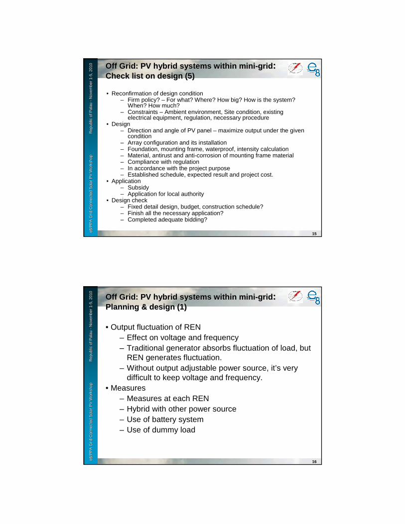
e8 /
PP
A D
SM
Wo
rksh
op
F
iji Is
lan
ds
No
vem
ber
2-6
, 200
9e8
/PP
A G
rid
Con
nect
ed S
olar
PV
Wor
ksho
p
R
epub
le8
/PP
A G
rid
Con
nect
ed S
olar
PV
Wor
ksho
p
R
epub
l ic o
f Pal
au
ic o
f Pal
au --
Nov
embe
r 1
Nov
embe
r 1 --
5, 2
010
5, 2
010
15
Off Grid: PV hybrid systems within miniOff Grid: PV hybrid systems within mini--gridgrid: : Check list on design (5)Check list on design (5)
• Reconfirmation of design condition– Firm policy? – For what? Where? How big? How is the system?
When? How much?– Constraints – Ambient environment, Site condition, existing
electrical equipment, regulation, necessary procedure• Design
– Direction and angle of PV panel – maximize output under the given condition
– Array configuration and its installation– Foundation, mounting frame, waterproof, intensity calculation– Material, antirust and anti-corrosion of mounting frame material– Compliance with regulation– In accordance with the project purpose– Established schedule, expected result and project cost.
• Application– Subsidy– Application for local authority
• Design check– Fixed detail design, budget, construction schedule?– Finish all the necessary application?– Completed adequate bidding?
e8 /
PP
A D
SM
Wo
rksh
op
F
iji Is
lan
ds
No
vem
ber
2-6
, 200
9e8
/PP
A G
rid
Con
nect
ed S
olar
PV
Wor
ksho
p
R
epub
le8
/PP
A G
rid
Con
nect
ed S
olar
PV
Wor
ksho
p
R
epub
l ic o
f Pal
au
ic o
f Pal
au --
Nov
embe
r 1
Nov
embe
r 1 --
5, 2
010
5, 2
010
16
Off Grid: PV hybrid systems within miniOff Grid: PV hybrid systems within mini--gridgrid: : Planning & designPlanning & design (1)(1)
• Output fluctuation of REN– Effect on voltage and frequency – Traditional generator absorbs fluctuation of load, but
REN generates fluctuation.– Without output adjustable power source, it’s very
difficult to keep voltage and frequency.• Measures
– Measures at each REN– Hybrid with other power source– Use of battery system– Use of dummy load
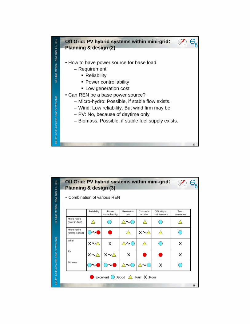
e8 /
PP
A D
SM
Wo
rksh
op
F
iji Is
lan
ds
No
vem
ber
2-6
, 200
9e8
/PP
A G
rid
Con
nect
ed S
olar
PV
Wor
ksho
p
R
epub
le8
/PP
A G
rid
Con
nect
ed S
olar
PV
Wor
ksho
p
R
epub
l ic o
f Pal
au
ic o
f Pal
au --
Nov
embe
r 1
Nov
embe
r 1 --
5, 2
010
5, 2
010
17
Off Grid: PV hybrid systems within miniOff Grid: PV hybrid systems within mini--gridgrid: : Planning & design (2)Planning & design (2)
• How to have power source for base load– Requirement
� Reliability� Power controllability� Low generation cost
• Can REN be a base power source?– Micro-hydro: Possible, if stable flow exists.– Wind: Low reliability. But wind firm may be.– PV: No, because of daytime only– Biomass: Possible, if stable fuel supply exists.
e8 /
PP
A D
SM
Wo
rksh
op
F
iji Is
lan
ds
No
vem
ber
2-6
, 200
9e8
/PP
A G
rid
Con
nect
ed S
olar
PV
Wor
ksho
p
R
epub
le8
/PP
A G
rid
Con
nect
ed S
olar
PV
Wor
ksho
p
R
epub
l ic o
f Pal
au
ic o
f Pal
au --
Nov
embe
r 1
Nov
embe
r 1 --
5, 2
010
5, 2
010
18
:Excellent :Good :Fair :Poor
Off Grid: PV hybrid systems within miniOff Grid: PV hybrid systems within mini--gridgrid: : Planning & design (3)Planning & design (3)
• Combination of various REN
Reliability Power controllability
Generation cost
Constrain on site
Difficulty on maintenance
Total evaluation
Micro-hydro(river-in-flow)
Micro-hydro(storage pond)
Wind
PV
Biomass

e8 /
PP
A D
SM
Wo
rksh
op
F
iji Is
lan
ds
No
vem
ber
2-6
, 200
9e8
/PP
A G
rid
Con
nect
ed S
olar
PV
Wor
ksho
p
R
epub
le8
/PP
A G
rid
Con
nect
ed S
olar
PV
Wor
ksho
p
R
epub
l ic o
f Pal
au
ic o
f Pal
au --
Nov
embe
r 1
Nov
embe
r 1 --
5, 2
010
5, 2
010
19
Off Grid: PV hybrid systems within miniOff Grid: PV hybrid systems within mini--gridgrid: : Planning & design (4)Planning & design (4)
• Hybrid of REN (without genset)a. Improve reliability
� Complementary combination:� Enlarge storage reservoir
b. Improve power controllability and realize output smoothing� Not one big REN, but many small REN
c. Common-use of electrical equipment
Power source for base load Biomass Micro-hydro(storage pond)
Micro-hydro(river-in-flow)
Wind PV
PV b a, b a b
Wind a, b, c, a, b, c, c
Micro-hydro(river-in-flow)
a, c a, c
Micro-hydro(storage pond)
a, c
Biomass:Excellent :Good :Fair :Poor
e8 /
PP
A D
SM
Wo
rksh
op
F
iji Is
lan
ds
No
vem
ber
2-6
, 200
9e8
/PP
A G
rid
Con
nect
ed S
olar
PV
Wor
ksho
p
R
epub
le8
/PP
A G
rid
Con
nect
ed S
olar
PV
Wor
ksho
p
R
epub
l ic o
f Pal
au
ic o
f Pal
au --
Nov
embe
r 1
Nov
embe
r 1 --
5, 2
010
5, 2
010
20
Off Grid: PV hybrid systems within miniOff Grid: PV hybrid systems within mini--gridgrid: : Planning & design of microPlanning & design of micro--hydrohydro
• Concept design of micro-hydro – Layout of major engineering structure– Identify head– Investigate information of water flow– Design of max water consumption
• Basic design of major engineering structure– Civil– Electrical
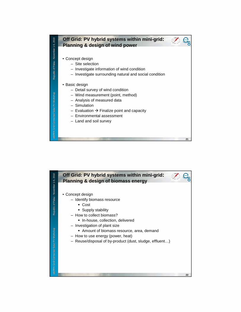
e8 /
PP
A D
SM
Wo
rksh
op
F
iji Is
lan
ds
No
vem
ber
2-6
, 200
9e8
/PP
A G
rid
Con
nect
ed S
olar
PV
Wor
ksho
p
R
epub
le8
/PP
A G
rid
Con
nect
ed S
olar
PV
Wor
ksho
p
R
epub
l ic o
f Pal
au
ic o
f Pal
au --
Nov
embe
r 1
Nov
embe
r 1 --
5, 2
010
5, 2
010
21
Off Grid: PV hybrid systems within miniOff Grid: PV hybrid systems within mini--gridgrid: : Planning & design of wind powerPlanning & design of wind power
• Concept design – Site selection– Investigate information of wind condition– Investigate surrounding natural and social condition
• Basic design– Detail survey of wind condition– Wind measurement (point, method)– Analysis of measured data– Simulation– Evaluation � Finalize point and capacity– Environmental assessment– Land and soil survey
e8 /
PP
A D
SM
Wo
rksh
op
F
iji Is
lan
ds
No
vem
ber
2-6
, 200
9e8
/PP
A G
rid
Con
nect
ed S
olar
PV
Wor
ksho
p
R
epub
le8
/PP
A G
rid
Con
nect
ed S
olar
PV
Wor
ksho
p
R
epub
l ic o
f Pal
au
ic o
f Pal
au --
Nov
embe
r 1
Nov
embe
r 1 --
5, 2
010
5, 2
010
22
Off Grid: PV hybrid systems within miniOff Grid: PV hybrid systems within mini--gridgrid: : Planning & design of biomass energyPlanning & design of biomass energy
• Concept design – Identify biomass resource
� Cost� Supply stability
– How to collect biomass?� In-house, collection, delivered
– Investigation of plant size� Amount of biomass resource, area, demand
– How to use energy (power, heat)– Reuse/disposal of by-product (dust, sludge, effluent…)

e8 /
PP
A D
SM
Wo
rksh
op
F
iji Is
lan
ds
No
vem
ber
2-6
, 200
9e8
/PP
A G
rid
Con
nect
ed S
olar
PV
Wor
ksho
p
R
epub
le8
/PP
A G
rid
Con
nect
ed S
olar
PV
Wor
ksho
p
R
epub
l ic o
f Pal
au
ic o
f Pal
au --
Nov
embe
r 1
Nov
embe
r 1 --
5, 2
010
5, 2
010
23
Off Grid: PV hybrid systems within miniOff Grid: PV hybrid systems within mini--gridgrid: : Operation & maintenanceOperation & maintenance
• Load forecasting is most important.• Aim to full utilize PV power.• Reserve battery energy for emergency case.• Adjust charge/discharge energy in accordance
with varying load.
Daytime: Battery charge by REN source Nighttime: Battery discharge for loadInvestigate charge/discharge timeCalculate required battery capacity
Source: NEDO

Grid Connected Solar PV WorkshopPalau
November 1-5,2010
Normal gridNormal grid(Examples of grid connected system)(Examples of grid connected system)
e8 /
PP
A D
SM
Wo
rksh
op
F
iji Is
lan
ds
No
vem
ber
2-6
, 200
9e8
/PP
A G
rid
Con
nect
ed S
olar
PV
Wor
ksho
p
R
epub
le8
/PP
A G
rid
Con
nect
ed S
olar
PV
Wor
ksho
p
R
epub
l ic o
f ic
of P
alau
Pal
au--
Nov
embe
r 1
Nov
embe
r 1 --
5, 2
010
5, 2
010
2
No Title Sub-t.itle Main Grid connection
Suppliedpower
Gen Size(approx.)
Genset Other RNE
Batterysystem
Note
(1) SHS DC SHS Off DC < 1kW No No Yes
AC SHS Off AC < 1kW No No Yes
(2) Mini grid PV Mini grid
Off AC 1 - 50kW No No Yes 50 to 600HouseholdsBattery charge station
PV hybrid systems within mini-grid
Off AC 10 - 500kW Optional (a few hours per day)
Windbiomassmicro-hydroetc.
Optional New components
(3) Grid connected Large PV system & Hybrid system
Grid connected large PV system
On AC > 40kW No No Optional With reliable grid (24H supply)
Grid connected hybrid system
On AC > 100kW Basically No. Optional(a few hours per day)
Windbiomassmicro-hydroetc.
Optional With reliable grid (24H supply)
Grid connectedGrid connected systemsystem
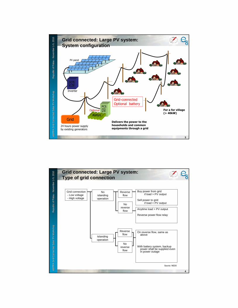
e8 /
PP
A D
SM
Wo
rksh
op
F
iji Is
lan
ds
No
vem
ber
2-6
, 200
9e8
/PP
A G
rid
Con
nect
ed S
olar
PV
Wor
ksho
p
R
epub
le8
/PP
A G
rid
Con
nect
ed S
olar
PV
Wor
ksho
p
R
epub
l ic o
f ic
of P
alau
Pal
au--
Nov
embe
r 1
Nov
embe
r 1 --
5, 2
010
5, 2
010
3
Grid connected: Large PV system: Grid connected: Large PV system: System configurationSystem configuration
PV panel
Inverter
For a for village (> 40kW)
Delivers the power to the households and common equipments through a grid
Grid
24 hours power supply by existing generators
Grid-connectedOptional battery
Battery
PCS
Optional
e8 /
PP
A D
SM
Wo
rksh
op
F
iji Is
lan
ds
No
vem
ber
2-6
, 200
9e8
/PP
A G
rid
Con
nect
ed S
olar
PV
Wor
ksho
p
R
epub
le8
/PP
A G
rid
Con
nect
ed S
olar
PV
Wor
ksho
p
R
epub
l ic o
f ic
of P
alau
Pal
au--
Nov
embe
r 1
Nov
embe
r 1 --
5, 2
010
5, 2
010
4
Grid connected: Large PV system:Grid connected: Large PV system:Type of grid connection Type of grid connection
Grid connection- Low voltage- High voltage
Noislanding operation
No reverse
flow
Reverse flow
Islanding operation
No reverse
flow
Reverse flow
Buy power from gridif load > PV output
Sell power to gridif load < PV output
Anytime load > PV output
Reverse power flow relay
On reverse flow, same as above
With battery system, backup power shall be supplied even in power outage
Source: NEDO
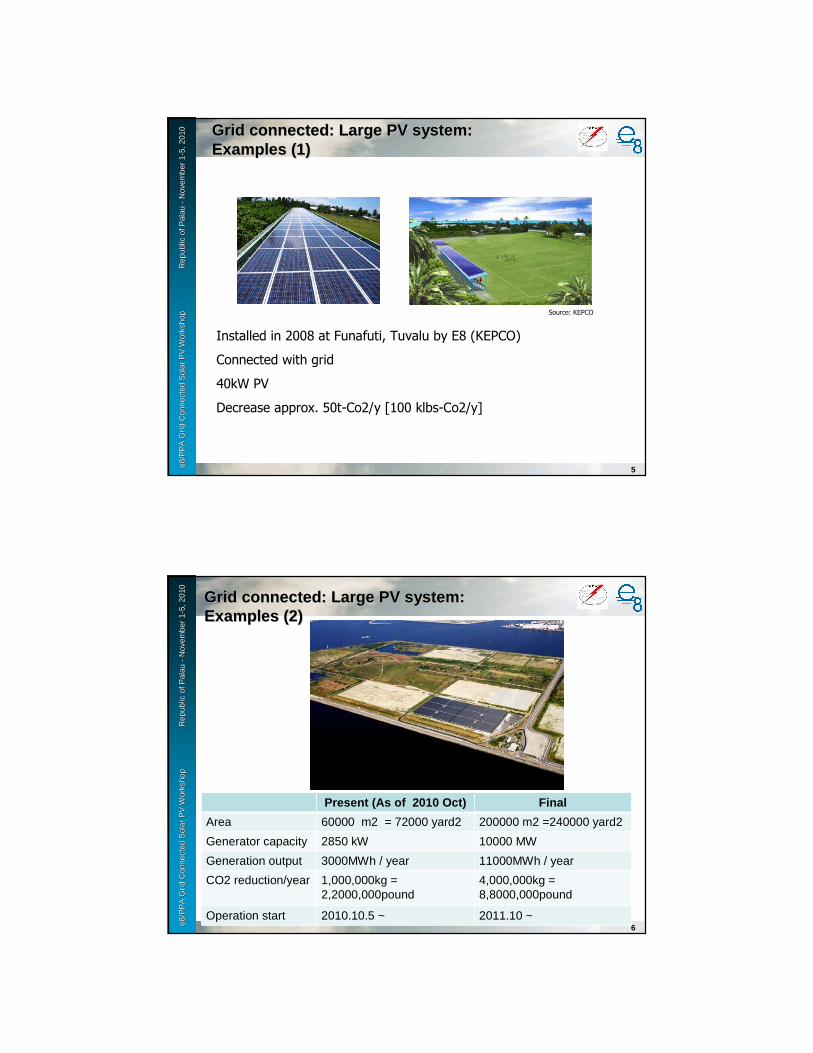
e8 /
PP
A D
SM
Wo
rksh
op
F
iji Is
lan
ds
No
vem
ber
2-6
, 200
9e8
/PP
A G
rid
Con
nect
ed S
olar
PV
Wor
ksho
p
R
epub
le8
/PP
A G
rid
Con
nect
ed S
olar
PV
Wor
ksho
p
R
epub
l ic o
f ic
of P
alau
Pal
au--
Nov
embe
r 1
Nov
embe
r 1 --
5, 2
010
5, 2
010
5
Grid connected: Large PV system: Grid connected: Large PV system: Examples (1)Examples (1)
Installed in 2008 at Funafuti, Tuvalu by E8 (KEPCO)
Connected with grid
40kW PV
Decrease approx. 50t-Co2/y [100 klbs-Co2/y]
Source: KEPCO
e8 /
PP
A D
SM
Wo
rksh
op
F
iji Is
lan
ds
No
vem
ber
2-6
, 200
9e8
/PP
A G
rid
Con
nect
ed S
olar
PV
Wor
ksho
p
R
epub
le8
/PP
A G
rid
Con
nect
ed S
olar
PV
Wor
ksho
p
R
epub
l ic o
f ic
of P
alau
Pal
au--
Nov
embe
r 1
Nov
embe
r 1 --
5, 2
010
5, 2
010
Grid connected: Large PV system: Grid connected: Large PV system: Examples (2)Examples (2)
6
Present (As of 2010 Oct) Final
Area 60000 m2 = 72000 yard2 200000 m2 =240000 yard2
Generator capacity 2850 kW 10000 MW
Generation output 3000MWh / year 11000MWh / year
CO2 reduction/year 1,000,000kg =2,2000,000pound
4,000,000kg =8,8000,000pound
Operation start 2010.10.5 ~ 2011.10 ~

e8 /
PP
A D
SM
Wo
rksh
op
F
iji Is
lan
ds
No
vem
ber
2-6
, 200
9e8
/PP
A G
rid
Con
nect
ed S
olar
PV
Wor
ksho
p
R
epub
le8
/PP
A G
rid
Con
nect
ed S
olar
PV
Wor
ksho
p
R
epub
l ic o
f ic
of P
alau
Pal
au--
Nov
embe
r 1
Nov
embe
r 1 --
5, 2
010
5, 2
010
7
Grid connected: Large PV system:Grid connected: Large PV system:Examples (3)Examples (3)
Installed in 2005 at Beijing, China by NEDO (TEPCO+PVTEC)
Office use plus connected with 10kV grid
140kW PV
Comparison of various kind of PV modules (crystalline, amorphous)
Source: NEDO
e8 /
PP
A D
SM
Wo
rksh
op
F
iji Is
lan
ds
No
vem
ber
2-6
, 200
9e8
/PP
A G
rid
Con
nect
ed S
olar
PV
Wor
ksho
p
R
epub
le8
/PP
A G
rid
Con
nect
ed S
olar
PV
Wor
ksho
p
R
epub
l ic o
f ic
of P
alau
Pal
au--
Nov
embe
r 1
Nov
embe
r 1 --
5, 2
010
5, 2
010
8
Grid connected: Large PV system:Grid connected: Large PV system:Examples (3)Examples (3)
Source: NEDO

e8 /
PP
A D
SM
Wo
rksh
op
F
iji Is
lan
ds
No
vem
ber
2-6
, 200
9e8
/PP
A G
rid
Con
nect
ed S
olar
PV
Wor
ksho
p
R
epub
le8
/PP
A G
rid
Con
nect
ed S
olar
PV
Wor
ksho
p
R
epub
l ic o
f ic
of P
alau
Pal
au--
Nov
embe
r 1
Nov
embe
r 1 --
5, 2
010
5, 2
010
9
Grid connected: Large PV system:Grid connected: Large PV system:Examples (4)Examples (4)
Installed in 2004-2007 at Ohta, Japan by NEDO (Kandenko et al.)
553 residential houses
Total 140kW PV, connected at 100V with 6.6kV distribution line
Evaluation of the islanding operation protection
Source: NEDO
e8 /
PP
A D
SM
Wo
rksh
op
F
iji Is
lan
ds
No
vem
ber
2-6
, 200
9e8
/PP
A G
rid
Con
nect
ed S
olar
PV
Wor
ksho
p
R
epub
le8
/PP
A G
rid
Con
nect
ed S
olar
PV
Wor
ksho
p
R
epub
l ic o
f ic
of P
alau
Pal
au--
Nov
embe
r 1
Nov
embe
r 1 --
5, 2
010
5, 2
010
10
Grid connected: Large PV system:Grid connected: Large PV system:Examples (4)Examples (4)
Installed in 2004-2007 at Ohta, Japan by NEDO (Kandenko et al.)
553 residential houses
Total 140kW PV, connected at 100V with 6.6kV distribution line
Evaluation of the islanding operation protection
Source: NEDO
PV
Load
Junction box
Inverter etc.

e8 /
PP
A D
SM
Wo
rksh
op
F
iji Is
lan
ds
No
vem
ber
2-6
, 200
9e8
/PP
A G
rid
Con
nect
ed S
olar
PV
Wor
ksho
p
R
epub
le8
/PP
A G
rid
Con
nect
ed S
olar
PV
Wor
ksho
p
R
epub
l ic o
f ic
of P
alau
Pal
au--
Nov
embe
r 1
Nov
embe
r 1 --
5, 2
010
5, 2
010
11
Grid connected: Large PV system: Grid connected: Large PV system: System configurationSystem configuration
PV panel
Inverter
For a for village (> 40kW)
Delivers the power to the households and common equipments through a grid
Grid
24 hours power supply by existing generators
Grid-connectedOptional battery
Battery
PCS
Optional
e8 /
PP
A D
SM
Wo
rksh
op
F
iji Is
lan
ds
No
vem
ber
2-6
, 200
9e8
/PP
A G
rid
Con
nect
ed S
olar
PV
Wor
ksho
p
R
epub
le8
/PP
A G
rid
Con
nect
ed S
olar
PV
Wor
ksho
p
R
epub
l ic o
f ic
of P
alau
Pal
au--
Nov
embe
r 1
Nov
embe
r 1 --
5, 2
010
5, 2
010
12
Grid connected: Large PV system:Grid connected: Large PV system:Type of grid connection Type of grid connection
Grid connection- Low voltage- High voltage
Noislanding operation
No reverse
flow
Reverse flow
Islanding operation
No reverse
flow
Reverse flow
Buy power from gridif load > PV output
Sell power to gridif load < PV output
Anytime load > PV output
Reverse power flow relay
On reverse flow, same as above
With battery system, backup power shall be supplied even in power outage
Source: NEDO

e8 /
PP
A D
SM
Wo
rksh
op
F
iji Is
lan
ds
No
vem
ber
2-6
, 200
9e8
/PP
A G
rid
Con
nect
ed S
olar
PV
Wor
ksho
p
R
epub
le8
/PP
A G
rid
Con
nect
ed S
olar
PV
Wor
ksho
p
R
epub
l ic o
f ic
of P
alau
Pal
au--
Nov
embe
r 1
Nov
embe
r 1 --
5, 2
010
5, 2
010
13
Grid connected: Large PV system: Grid connected: Large PV system: Examples (1)Examples (1)
Installed in 2008 at Funafuti, Tuvalu by E8 (KEPCO)
Connected with grid
40kW PV
Decrease approx. 50t-Co2/y [100 klbs-Co2/y]
Source: KEPCO
e8 /
PP
A D
SM
Wo
rksh
op
F
iji Is
lan
ds
No
vem
ber
2-6
, 200
9e8
/PP
A G
rid
Con
nect
ed S
olar
PV
Wor
ksho
p
R
epub
le8
/PP
A G
rid
Con
nect
ed S
olar
PV
Wor
ksho
p
R
epub
l ic o
f ic
of P
alau
Pal
au--
Nov
embe
r 1
Nov
embe
r 1 --
5, 2
010
5, 2
010
14
Grid connected: Large PV system:Grid connected: Large PV system:Examples (2)Examples (2)
Installed in 2005 at Beijing, China by NEDO (TEPCO+PVTEC)
Office use plus connected with 10kV grid
140kW PV
Comparison of various kind of PV modules (crystalline, amorphous)
Source: NEDO

e8 /
PP
A D
SM
Wo
rksh
op
F
iji Is
lan
ds
No
vem
ber
2-6
, 200
9e8
/PP
A G
rid
Con
nect
ed S
olar
PV
Wor
ksho
p
R
epub
le8
/PP
A G
rid
Con
nect
ed S
olar
PV
Wor
ksho
p
R
epub
l ic o
f ic
of P
alau
Pal
au--
Nov
embe
r 1
Nov
embe
r 1 --
5, 2
010
5, 2
010
15
Grid connected: Large PV system:Grid connected: Large PV system:Examples (2)Examples (2)
Source: NEDO
e8 /
PP
A D
SM
Wo
rksh
op
F
iji Is
lan
ds
No
vem
ber
2-6
, 200
9e8
/PP
A G
rid
Con
nect
ed S
olar
PV
Wor
ksho
p
R
epub
le8
/PP
A G
rid
Con
nect
ed S
olar
PV
Wor
ksho
p
R
epub
l ic o
f ic
of P
alau
Pal
au--
Nov
embe
r 1
Nov
embe
r 1 --
5, 2
010
5, 2
010
16
Grid connected: Large PV system:Grid connected: Large PV system:Examples (3)Examples (3)
Installed in 2004-2007 at Ohta, Japan by NEDO (Kandenko et al.)
553 residential houses
Total 140kW PV, connected at 100V with 6.6kV distribution line
Evaluation of the islanding operation protection
Source: NEDO

e8 /
PP
A D
SM
Wo
rksh
op
F
iji Is
lan
ds
No
vem
ber
2-6
, 200
9e8
/PP
A G
rid
Con
nect
ed S
olar
PV
Wor
ksho
p
R
epub
le8
/PP
A G
rid
Con
nect
ed S
olar
PV
Wor
ksho
p
R
epub
l ic o
f ic
of P
alau
Pal
au--
Nov
embe
r 1
Nov
embe
r 1 --
5, 2
010
5, 2
010
17
Grid connected: Large PV system:Grid connected: Large PV system:Examples (3)Examples (3)
Installed in 2004-2007 at Ohta, Japan by NEDO (Kandenko et al.)
553 residential houses
Total 140kW PV, connected at 100V with 6.6kV distribution line
Evaluation of the islanding operation protection
Source: NEDO
PV
Load
Junction box
Inverter etc.
e8 /
PP
A D
SM
Wo
rksh
op
F
iji Is
lan
ds
No
vem
ber
2-6
, 200
9e8
/PP
A G
rid
Con
nect
ed S
olar
PV
Wor
ksho
p
R
epub
le8
/PP
A G
rid
Con
nect
ed S
olar
PV
Wor
ksho
p
R
epub
l ic o
f ic
of P
alau
Pal
au--
Nov
embe
r 1
Nov
embe
r 1 --
5, 2
010
5, 2
010
Other various applications of PVOther various applications of PV( On the factory roof )( On the factory roof )
18
Capacity:820kW Capacity:50kW
Capacity:260kW
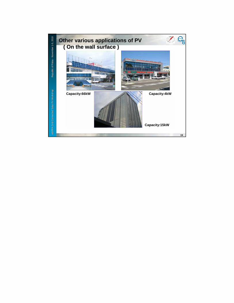
e8 /
PP
A D
SM
Wo
rksh
op
F
iji Is
lan
ds
No
vem
ber
2-6
, 200
9e8
/PP
A G
rid
Con
nect
ed S
olar
PV
Wor
ksho
p
R
epub
le8
/PP
A G
rid
Con
nect
ed S
olar
PV
Wor
ksho
p
R
epub
l ic o
f ic
of P
alau
Pal
au--
Nov
embe
r 1
Nov
embe
r 1 --
5, 2
010
5, 2
010
Other various applications of PVOther various applications of PV( On the wall surface )( On the wall surface )
19
Capacity:66kW Capacity:4kW
Capacity:15kW

Grid Connected Solar PV WorkshopPalau
November 1-5,2010
Technical requirementsTechnical requirementsfor grid interconnectiofor grid interconnectio nn
e8 /
PP
A D
SM
Wo
rksh
op
F
iji Is
lan
ds
No
vem
ber
2-6
, 200
9e8
/PP
A G
rid
Con
nect
ed S
olar
PV
Wor
ksho
p
R
epub
le8
/PP
A G
rid
Con
nect
ed S
olar
PV
Wor
ksho
p
R
epub
l ic o
f Pal
au
ic o
f Pal
au --
Nov
embe
r 1
Nov
embe
r 1 --
5, 2
010
5, 2
010
〇〇〇〇Easier to maintain power quality
〇〇〇〇Boost the operating rates of generator
〇〇〇〇Absorb fluctuation of generator output
(ex. PV, wind power)
〇〇〇〇Improve reliability and flexibility in case of
generator’s fault or maintenance check
〇〇〇〇Chance to sell electric power to the power
company
The merit of grid interconnectionfrom the generator installer
2
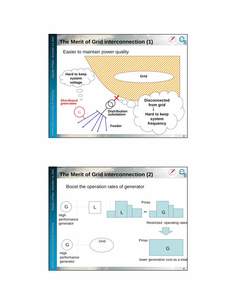
e8 /
PP
A D
SM
Wo
rksh
op
F
iji Is
lan
ds
No
vem
ber
2-6
, 200
9e8
/PP
A G
rid
Con
nect
ed S
olar
PV
Wor
ksho
p
R
epub
le8
/PP
A G
rid
Con
nect
ed S
olar
PV
Wor
ksho
p
R
epub
l ic o
f Pal
au
ic o
f Pal
au --
Nov
embe
r 1
Nov
embe
r 1 --
5, 2
010
5, 2
010
3
G
Feeder
Distributed generation
Hard to keep system voltage
×××× Disconnected from grid
↓↓↓↓Hard to keep
system frequency
Grid
Distribution substation
The Merit of Grid interconnection (1)
Easier to maintain power qualitye8
/ P
PA
DS
M W
ork
sho
p
Fiji
Isla
nd
s N
ove
mb
er 2
-6, 2
009
e8/P
PA
Gri
d C
onne
cted
Sol
ar P
V W
orks
hop
Rep
ubl
e8/P
PA
Gri
d C
onne
cted
Sol
ar P
V W
orks
hop
Rep
ubl ic
of P
alau
ic
of P
alau
--N
ovem
ber
1N
ovem
ber
1 --5,
201
05,
201
0
4
The Merit of Grid interconnection (2)
Boost the operation rates of generator
G L
High performance generator
L G====
Pmax
G
High performance generator
Grid
Restricted operating rates
Pmax
G
lower generation cost as a total
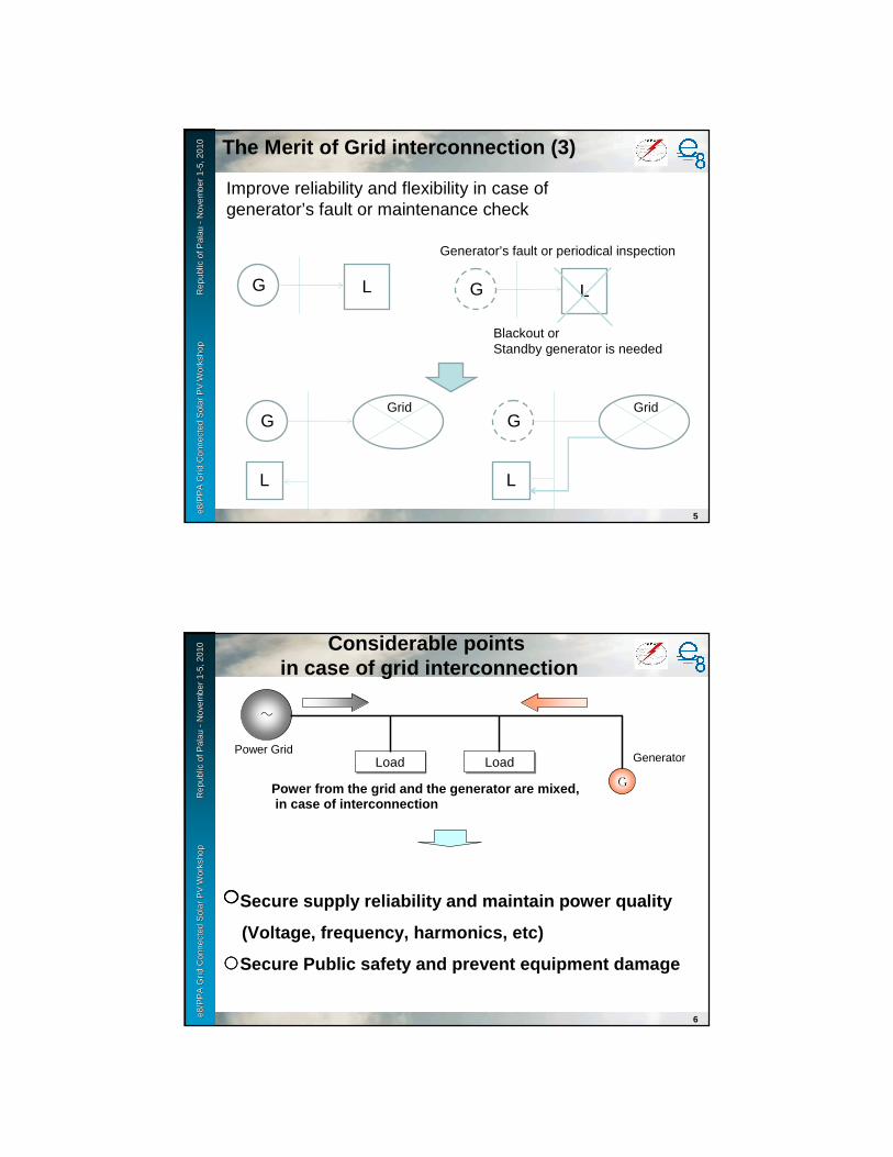
e8 /
PP
A D
SM
Wo
rksh
op
F
iji Is
lan
ds
No
vem
ber
2-6
, 200
9e8
/PP
A G
rid
Con
nect
ed S
olar
PV
Wor
ksho
p
R
epub
le8
/PP
A G
rid
Con
nect
ed S
olar
PV
Wor
ksho
p
R
epub
l ic o
f Pal
au
ic o
f Pal
au --
Nov
embe
r 1
Nov
embe
r 1 --
5, 2
010
5, 2
010
5
The Merit of Grid interconnection (3)
Improve reliability and flexibility in case of generator’s fault or maintenance check
G L
GGrid
G L
Generator’s fault or periodical inspection
Blackout orStandby generator is needed
L
GGrid
L
e8 /
PP
A D
SM
Wo
rksh
op
F
iji Is
lan
ds
No
vem
ber
2-6
, 200
9e8
/PP
A G
rid
Con
nect
ed S
olar
PV
Wor
ksho
p
R
epub
le8
/PP
A G
rid
Con
nect
ed S
olar
PV
Wor
ksho
p
R
epub
l ic o
f Pal
au
ic o
f Pal
au --
Nov
embe
r 1
Nov
embe
r 1 --
5, 2
010
5, 2
010 Considerable points
in case of grid interconnection
6
~
G
Power GridLoadLoad
Power from the grid and the generator are mixed,in case of interconnection
LoadLoad
〇〇〇〇Secure supply reliability and maintain power qualit y
(Voltage, frequency, harmonics, etc)
○○○○Secure Public safety and prevent equipment damage
Generator
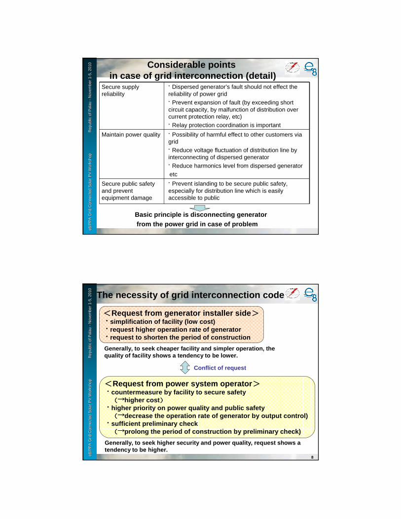
e8 /
PP
A D
SM
Wo
rksh
op
F
iji Is
lan
ds
No
vem
ber
2-6
, 200
9e8
/PP
A G
rid
Con
nect
ed S
olar
PV
Wor
ksho
p
R
epub
le8
/PP
A G
rid
Con
nect
ed S
olar
PV
Wor
ksho
p
R
epub
l ic o
f Pal
au
ic o
f Pal
au --
Nov
embe
r 1
Nov
embe
r 1 --
5, 2
010
5, 2
010 Considerable points
in case of grid interconnection (detail)
Basic principle is disconnecting generatorfrom the power grid in case of problem
Secure supply reliability
・Dispersed generator’s fault should not effect the reliability of power grid
・Prevent expansion of fault (by exceeding short circuit capacity, by malfunction of distribution over current protection relay, etc)
・Relay protection coordination is important
Maintain power quality ・Possibility of harmful effect to other customers via grid
・Reduce voltage fluctuation of distribution line by interconnecting of dispersed generator
・Reduce harmonics level from dispersed generatoretc
Secure public safety and prevent equipment damage
・Prevent islanding to be secure public safety, especially for distribution line which is easily accessible to public
e8 /
PP
A D
SM
Wo
rksh
op
F
iji Is
lan
ds
No
vem
ber
2-6
, 200
9e8
/PP
A G
rid
Con
nect
ed S
olar
PV
Wor
ksho
p
R
epub
le8
/PP
A G
rid
Con
nect
ed S
olar
PV
Wor
ksho
p
R
epub
l ic o
f Pal
au
ic o
f Pal
au --
Nov
embe
r 1
Nov
embe
r 1 --
5, 2
010
5, 2
010
The necessity of grid interconnection code
8
<<<<Request from generator installer side >>>>・・・・simplification of facility (low cost)・・・・request higher operation rate of generator・・・・request to shorten the period of construction
<<<<Request from power system operator >>>>・・・・countermeasure by facility to secure safety
(→(→(→(→higher cost ))))・・・・higher priority on power quality and public safety
(→(→(→(→decrease the operation rate of generator by output control)・・・・sufficient preliminary check
(→(→(→(→prolong the period of construction by preliminary c heck)
Generally, to seek higher security and power qualit y, request shows a tendency to be higher.
Generally, to seek cheaper facility and simpler ope ration, the quality of facility shows a tendency to be lower.
Conflict of request

e8 /
PP
A D
SM
Wo
rksh
op
F
iji Is
lan
ds
No
vem
ber
2-6
, 200
9e8
/PP
A G
rid
Con
nect
ed S
olar
PV
Wor
ksho
p
R
epub
le8
/PP
A G
rid
Con
nect
ed S
olar
PV
Wor
ksho
p
R
epub
l ic o
f Pal
au
ic o
f Pal
au --
Nov
embe
r 1
Nov
embe
r 1 --
5, 2
010
5, 2
010 The necessity of grid interconnection code
(continue)
9
Interconnection to power grid of many, various type of generator
Effect to operation, administration, maintenance of
Power system,etc
To harmonize request from both side, to secure equality and transparency of generator interconnecting process, grid interconnection code is necessary.
To harmonize request from both side, to secure equality and transparency of generator interconnecting process, grid interconnection code is necessary.
<<<<Request from generator installer side >>>>
<<<<Request from power system operator >>>>
e8 /
PP
A D
SM
Wo
rksh
op
F
iji Is
lan
ds
No
vem
ber
2-6
, 200
9e8
/PP
A G
rid
Con
nect
ed S
olar
PV
Wor
ksho
p
R
epub
le8
/PP
A G
rid
Con
nect
ed S
olar
PV
Wor
ksho
p
R
epub
l ic o
f Pal
au
ic o
f Pal
au --
Nov
embe
r 1
Nov
embe
r 1 --
5, 2
010
5, 2
010 Category of grid interconnection
by voltage level
Category Power Capacity per customer (P)
Low voltage distribution line(100V, 200V)
P < 50kW(in principle)
High voltage distribution line(6600V)
P < 2000kW(in principle)
Extra high voltage line 2000kW <= P(in principle)
Technical requirement for grid interconnection is partly different according to the category
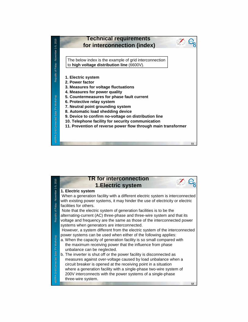
e8 /
PP
A D
SM
Wo
rksh
op
F
iji Is
lan
ds
No
vem
ber
2-6
, 200
9e8
/PP
A G
rid
Con
nect
ed S
olar
PV
Wor
ksho
p
R
epub
le8
/PP
A G
rid
Con
nect
ed S
olar
PV
Wor
ksho
p
R
epub
l ic o
f Pal
au
ic o
f Pal
au --
Nov
embe
r 1
Nov
embe
r 1 --
5, 2
010
5, 2
010 Technical requirements
for interconnection (index)
11
1. Electric system2. Power factor3. Measures for voltage fluctuations4. Measures for power quality5. Countermeasures for phase fault current6. Protective relay system7. Neutral point grounding system8. Automatic load shedding device9. Device to confirm no-voltage on distribution lin e10. Telephone facility for security communication11. Prevention of reverse power flow through main t ransformer
The below index is the example of grid interconnection to high voltage distribution line (6600V).
e8 /
PP
A D
SM
Wo
rksh
op
F
iji Is
lan
ds
No
vem
ber
2-6
, 200
9e8
/PP
A G
rid
Con
nect
ed S
olar
PV
Wor
ksho
p
R
epub
le8
/PP
A G
rid
Con
nect
ed S
olar
PV
Wor
ksho
p
R
epub
l ic o
f Pal
au
ic o
f Pal
au --
Nov
embe
r 1
Nov
embe
r 1 --
5, 2
010
5, 2
010 TR for interconnection
1.Electric system
12
1. Electric systemWhen a generation facility with a different electric system is interconnectedwith existing power systems, it may hinder the use of electricity or electricfacilities for others.Note that the electric system of generation facilities is to be thealternating-current (AC) three-phase and three-wire system and that itsvoltage and frequency are the same as those of the interconnected powersystems when generators are interconnected.However, a system different from the electric system of the interconnectedpower systems can be used when either of the following applies:a. When the capacity of generation facility is so small compared with
the maximum receiving power that the influence from phaseunbalance can be neglected.
b. The inverter is shut off or the power facility is disconnected asmeasures against over-voltage caused by load unbalance when acircuit breaker is opened at the receiving point in a situationwhere a generation facility with a single-phase two-wire system of200V interconnects with the power systems of a single-phasethree-wire system.

e8 /
PP
A D
SM
Wo
rksh
op
F
iji Is
lan
ds
No
vem
ber
2-6
, 200
9e8
/PP
A G
rid
Con
nect
ed S
olar
PV
Wor
ksho
p
R
epub
le8
/PP
A G
rid
Con
nect
ed S
olar
PV
Wor
ksho
p
R
epub
l ic o
f Pal
au
ic o
f Pal
au --
Nov
embe
r 1
Nov
embe
r 1 --
5, 2
010
5, 2
010 TR for interconnection
1.Electric system
13
b. The inverter is shut off or the power facility is disconnected asmeasures against over-voltage caused by load unbalance when acircuit breaker is opened at the receiving point in a situationwhere a generation facility with a single-phase two-wire system of200V interconnects with the power systems of a single-phasethree-wire system.
e8 /
PP
A D
SM
Wo
rksh
op
F
iji Is
lan
ds
No
vem
ber
2-6
, 200
9e8
/PP
A G
rid
Con
nect
ed S
olar
PV
Wor
ksho
p
R
epub
le8
/PP
A G
rid
Con
nect
ed S
olar
PV
Wor
ksho
p
R
epub
l ic o
f Pal
au
ic o
f Pal
au --
Nov
embe
r 1
Nov
embe
r 1 --
5, 2
010
5, 2
010 TR for interconnection
2.Power factor
14
2. Power factorWhen generators are interconnected with the system, it is necessary tocontrol reactive power in coordination with the generation facilities of power company and others so as to maintain the appropriate system voltage.When a new generator is interconnected, the power factor of thegeneration facilities is to be as follows.
In principle, the power factor of generation facilities should be 0.85 or more at the receiving point. Further, it should not be a leading power factor when viewed from the power systems to prevent the voltage from increasing (or a lagging power factor when viewed from generation facilities).However, the power factor can be below 0.85 when either of the followingapplies:

e8 /
PP
A D
SM
Wo
rksh
op
F
iji Is
lan
ds
No
vem
ber
2-6
, 200
9e8
/PP
A G
rid
Con
nect
ed S
olar
PV
Wor
ksho
p
R
epub
le8
/PP
A G
rid
Con
nect
ed S
olar
PV
Wor
ksho
p
R
epub
l ic o
f Pal
au
ic o
f Pal
au --
Nov
embe
r 1
Nov
embe
r 1 --
5, 2
010
5, 2
010 TR for interconnection
2.Power factor
15
a. It is unavoidable for preventing voltage increase. (In this case,the power factor at the receiving point can be controlled up to 0.8.)
b. An inverter with small output is used or the power factor at thereceiving point is deemed appropriate. (In this case, the powerfactor of generation facilities is over 0.85 when controlling reactivepower and is over 0.95 when not controlling it.)
If a reverse power flow does not exist, in principle the power factor ofgeneration facilities at the servicing point of end-use customers should be 0.85 or more in lagging power factor in order to prevent the voltage from decreasing. Further, it should not be a leading power factor when viewed from power systems (or a lagging power factor when viewedfrom generation facilities).
e8 /
PP
A D
SM
Wo
rksh
op
F
iji Is
lan
ds
No
vem
ber
2-6
, 200
9e8
/PP
A G
rid
Con
nect
ed S
olar
PV
Wor
ksho
p
R
epub
le8
/PP
A G
rid
Con
nect
ed S
olar
PV
Wor
ksho
p
R
epub
l ic o
f Pal
au
ic o
f Pal
au --
Nov
embe
r 1
Nov
embe
r 1 --
5, 2
010
5, 2
010 TR for interconnection
3. Measures for voltage fluctuations
16
3. Measures for voltage fluctuationsIf the system voltage cannot be properly maintained due to voltagefluctuations on power systems when a generator is interconnected, there may be a negative impact on the stable facility operation.In principle, those who interconnect a generation facility with power systems need to take the following measures to control the voltage in order to prevent deviation from the appropriate system voltage when generators are connected to the system.- If a disconnection of generation may cause the voltage of end-use customers interconnecting at low voltage to deviate from the appropriate voltage value (101±6V, 202±20V) when connected to high voltage distribution lines, measures are taken to automatically limit theload. If this measure is ineffective, more distribution lines are usedor exclusive-use lines are connected.

e8 /
PP
A D
SM
Wo
rksh
op
F
iji Is
lan
ds
No
vem
ber
2-6
, 200
9e8
/PP
A G
rid
Con
nect
ed S
olar
PV
Wor
ksho
p
R
epub
le8
/PP
A G
rid
Con
nect
ed S
olar
PV
Wor
ksho
p
R
epub
l ic o
f Pal
au
ic o
f Pal
au --
Nov
embe
r 1
Nov
embe
r 1 --
5, 2
010
5, 2
010
17
Voltage fluctuation on disconnectionVoltage fluctuation on disconnection
Automatic load shedding shall be implemented by generator owner
If not effective, use of exclusive line or reinforcing feeder shall be made by the cost of generator owner.
G L
Voltage
Deviation
Disconnection
Load increase
Deviation in voltage
G L
Maintain voltage
Load shedding
Load decrease
Maintain voltage
Voltage
e8 /
PP
A D
SM
Wo
rksh
op
F
iji Is
lan
ds
No
vem
ber
2-6
, 200
9e8
/PP
A G
rid
Con
nect
ed S
olar
PV
Wor
ksho
p
R
epub
le8
/PP
A G
rid
Con
nect
ed S
olar
PV
Wor
ksho
p
R
epub
l ic o
f Pal
au
ic o
f Pal
au --
Nov
embe
r 1
Nov
embe
r 1 --
5, 2
010
5, 2
010 TR for interconnection
3. Measures for voltage fluctuations
18
- If a reverse power flow from generation may cause the voltage ofend-use customers interconnecting at low voltage to deviate fromthe appropriate voltage value (101±6V, 202±20V), automaticvoltage control will take place. If this measure is ineffective, moredistribution lines are used or exclusive-use lines are connected.- When using synchronous generators, they should be of the typeswith damping winding (including a synchronous generator withoutdamping winding that has the hunting-prevention effectequivalent to or more than that of the damping winding type). Atthe same time, automatic synchronism detection devices need to beinstalled. If the system voltage may deviate from the propervalue (within 10% of the normal value) due to the voltage dip whilebeing paralleled in (induction generators are used), currentlimiting reactors or similar devices need to be installed. However,if such measures are still ineffective synchronous generators willbe required.
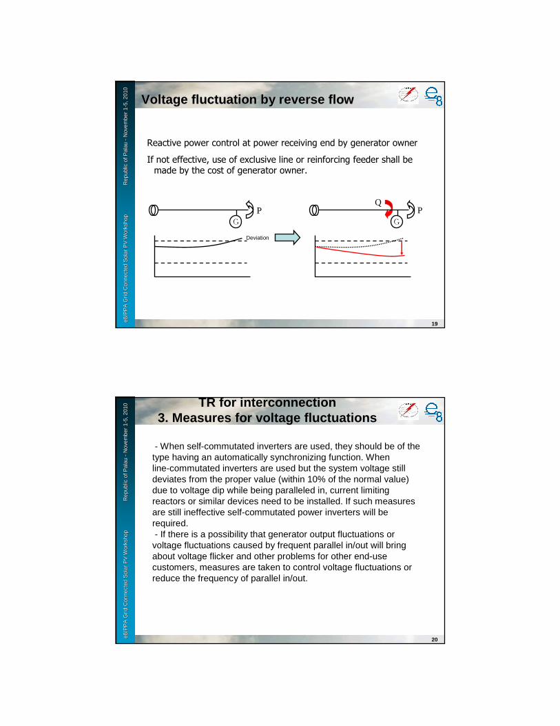
e8 /
PP
A D
SM
Wo
rksh
op
F
iji Is
lan
ds
No
vem
ber
2-6
, 200
9e8
/PP
A G
rid
Con
nect
ed S
olar
PV
Wor
ksho
p
R
epub
le8
/PP
A G
rid
Con
nect
ed S
olar
PV
Wor
ksho
p
R
epub
l ic o
f Pal
au
ic o
f Pal
au --
Nov
embe
r 1
Nov
embe
r 1 --
5, 2
010
5, 2
010
19
Q
GP
Deviation
GP
Voltage fluctuation by reverse flowVoltage fluctuation by reverse flow
Reactive power control at power receiving end by generator owner
If not effective, use of exclusive line or reinforcing feeder shall be made by the cost of generator owner.
e8 /
PP
A D
SM
Wo
rksh
op
F
iji Is
lan
ds
No
vem
ber
2-6
, 200
9e8
/PP
A G
rid
Con
nect
ed S
olar
PV
Wor
ksho
p
R
epub
le8
/PP
A G
rid
Con
nect
ed S
olar
PV
Wor
ksho
p
R
epub
l ic o
f Pal
au
ic o
f Pal
au --
Nov
embe
r 1
Nov
embe
r 1 --
5, 2
010
5, 2
010 TR for interconnection
3. Measures for voltage fluctuations
20
- When self-commutated inverters are used, they should be of thetype having an automatically synchronizing function. Whenline-commutated inverters are used but the system voltage stilldeviates from the proper value (within 10% of the normal value)due to voltage dip while being paralleled in, current limitingreactors or similar devices need to be installed. If such measuresare still ineffective self-commutated power inverters will berequired.- If there is a possibility that generator output fluctuations orvoltage fluctuations caused by frequent parallel in/out will bringabout voltage flicker and other problems for other end-usecustomers, measures are taken to control voltage fluctuations orreduce the frequency of parallel in/out.
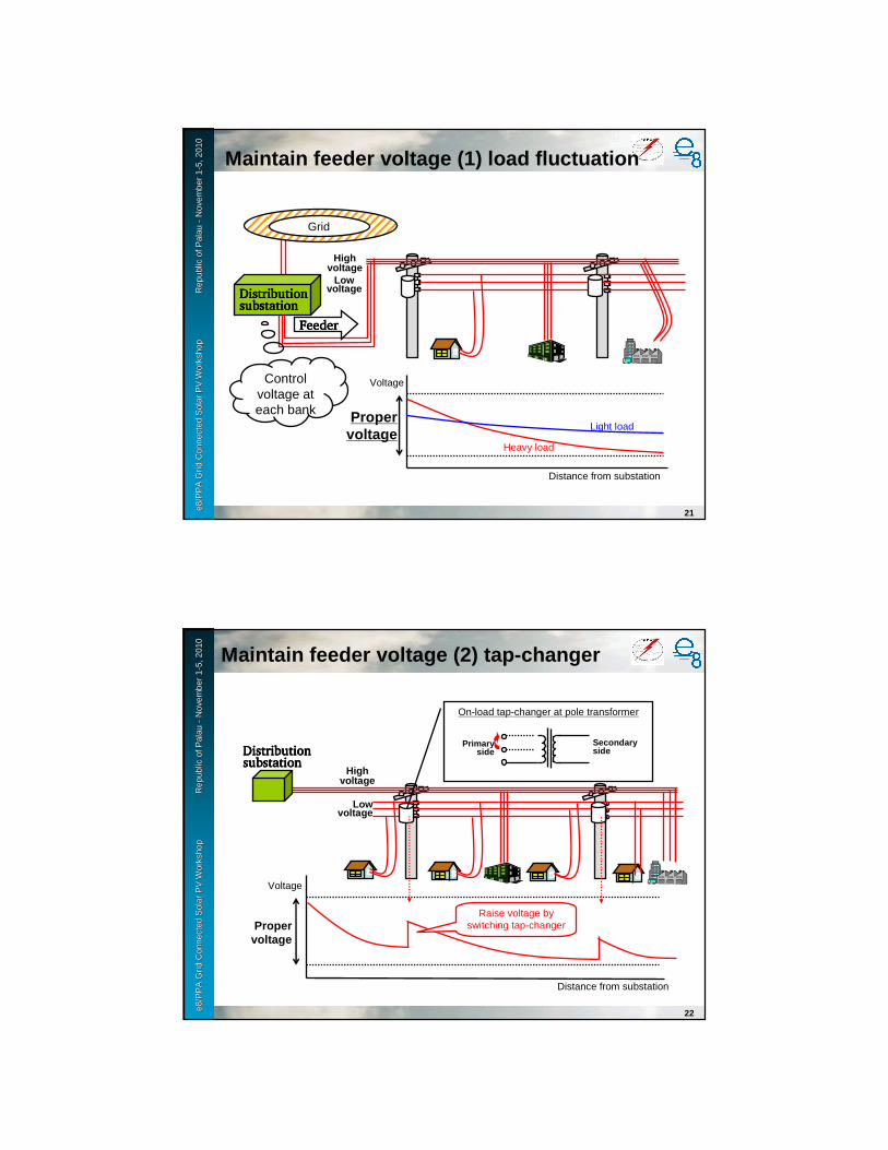
e8 /
PP
A D
SM
Wo
rksh
op
F
iji Is
lan
ds
No
vem
ber
2-6
, 200
9e8
/PP
A G
rid
Con
nect
ed S
olar
PV
Wor
ksho
p
R
epub
le8
/PP
A G
rid
Con
nect
ed S
olar
PV
Wor
ksho
p
R
epub
l ic o
f Pal
au
ic o
f Pal
au --
Nov
embe
r 1
Nov
embe
r 1 --
5, 2
010
5, 2
010
21
Distribution Distribution Distribution Distribution substationsubstationsubstationsubstation
Grid
FeederFeederFeederFeeder
Voltage
Distance from substation
Proper voltage
Heavy load
Light load
Control voltage at each bank
Low voltage
Highvoltage
Maintain feeder voltage (1) load fluctuation
e8 /
PP
A D
SM
Wo
rksh
op
F
iji Is
lan
ds
No
vem
ber
2-6
, 200
9e8
/PP
A G
rid
Con
nect
ed S
olar
PV
Wor
ksho
p
R
epub
le8
/PP
A G
rid
Con
nect
ed S
olar
PV
Wor
ksho
p
R
epub
l ic o
f Pal
au
ic o
f Pal
au --
Nov
embe
r 1
Nov
embe
r 1 --
5, 2
010
5, 2
010
22
Distribution Distribution Distribution Distribution substationsubstationsubstationsubstation
Voltage
Distance from substation
Proper voltage
On-load tap-changer at pole transformer
Raise voltage by switching tap-changer
Low voltage
Highvoltage
Secondary side
Primary side
Maintain feeder voltage (2) tap-changer

e8 /
PP
A D
SM
Wo
rksh
op
F
iji Is
lan
ds
No
vem
ber
2-6
, 200
9e8
/PP
A G
rid
Con
nect
ed S
olar
PV
Wor
ksho
p
R
epub
le8
/PP
A G
rid
Con
nect
ed S
olar
PV
Wor
ksho
p
R
epub
l ic o
f Pal
au
ic o
f Pal
au --
Nov
embe
r 1
Nov
embe
r 1 --
5, 2
010
5, 2
010
23
Distribution substationDistribution substationDistribution substationDistribution substation
Voltage
SVR(Step
voltage Regulator)
Raise voltage by SVR
Low voltage
Highvoltage
Proper voltage
Distance from substation
Control secondary voltage by monitoring current and changing tap of transformer
Maintain feeder voltage (3) SVR
e8 /
PP
A D
SM
Wo
rksh
op
F
iji Is
lan
ds
No
vem
ber
2-6
, 200
9e8
/PP
A G
rid
Con
nect
ed S
olar
PV
Wor
ksho
p
R
epub
le8
/PP
A G
rid
Con
nect
ed S
olar
PV
Wor
ksho
p
R
epub
l ic o
f Pal
au
ic o
f Pal
au --
Nov
embe
r 1
Nov
embe
r 1 --
5, 2
010
5, 2
010
24
Heavy load
Light load
Deviation from proper voltage
Distributed Generation
Reverse power flowDistribution substationDistribution substationDistribution substationDistribution substation
Voltage
Low voltage
Highvoltage
Proper voltage
Distance from substation
Maintain feeder voltage (4) reverse flow
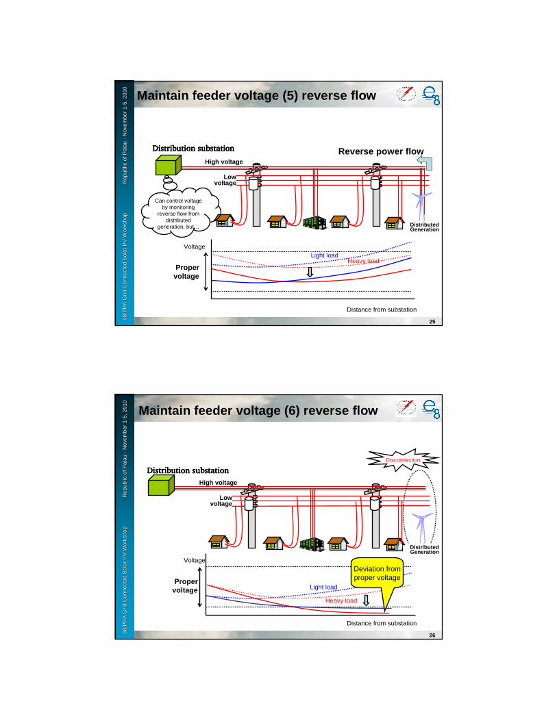
e8 /
PP
A D
SM
Wo
rksh
op
F
iji Is
lan
ds
No
vem
ber
2-6
, 200
9e8
/PP
A G
rid
Con
nect
ed S
olar
PV
Wor
ksho
p
R
epub
le8
/PP
A G
rid
Con
nect
ed S
olar
PV
Wor
ksho
p
R
epub
l ic o
f Pal
au
ic o
f Pal
au --
Nov
embe
r 1
Nov
embe
r 1 --
5, 2
010
5, 2
010
25
Heavy load
Can control voltage by monitoring
reverse flow from distributed
generation, but…
Light load
Distribution substationDistribution substationDistribution substationDistribution substation
Voltage
Low voltage
High voltage
Proper voltage
Distance from substation
Distributed Generation
Reverse power flow
Maintain feeder voltage (5) reverse flow
e8 /
PP
A D
SM
Wo
rksh
op
F
iji Is
lan
ds
No
vem
ber
2-6
, 200
9e8
/PP
A G
rid
Con
nect
ed S
olar
PV
Wor
ksho
p
R
epub
le8
/PP
A G
rid
Con
nect
ed S
olar
PV
Wor
ksho
p
R
epub
l ic o
f Pal
au
ic o
f Pal
au --
Nov
embe
r 1
Nov
embe
r 1 --
5, 2
010
5, 2
010
26
Heavy load
Light load
Distribution substationDistribution substationDistribution substationDistribution substation
Voltage
Low voltage
High voltage
Proper voltage
Distance from substation
Distributed Generation
Disconnection
Deviation from proper voltage
Maintain feeder voltage (6) reverse flow
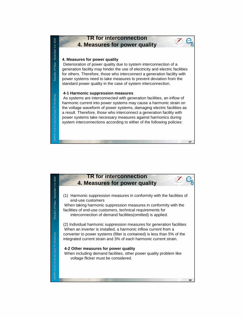
e8 /
PP
A D
SM
Wo
rksh
op
F
iji Is
lan
ds
No
vem
ber
2-6
, 200
9e8
/PP
A G
rid
Con
nect
ed S
olar
PV
Wor
ksho
p
R
epub
le8
/PP
A G
rid
Con
nect
ed S
olar
PV
Wor
ksho
p
R
epub
l ic o
f Pal
au
ic o
f Pal
au --
Nov
embe
r 1
Nov
embe
r 1 --
5, 2
010
5, 2
010 TR for interconnection
4. Measures for power quality
27
4. Measures for power qualityDeterioration of power quality due to system interconnection of a generation facility may hinder the use of electricity and electric facilities for others. Therefore, those who interconnect a generation facility with power systems need to take measures to prevent deviation from the standard power quality in the case of system interconnection.
4-1 Harmonic suppression measuresAs systems are interconnected with generation facilities, an inflow ofharmonic current into power systems may cause a harmonic strain on the voltage waveform of power systems, damaging electric facilities as a result. Therefore, those who interconnect a generation facility with power systems take necessary measures against harmonics during system interconnections according to either of the following policies:
e8 /
PP
A D
SM
Wo
rksh
op
F
iji Is
lan
ds
No
vem
ber
2-6
, 200
9e8
/PP
A G
rid
Con
nect
ed S
olar
PV
Wor
ksho
p
R
epub
le8
/PP
A G
rid
Con
nect
ed S
olar
PV
Wor
ksho
p
R
epub
l ic o
f Pal
au
ic o
f Pal
au --
Nov
embe
r 1
Nov
embe
r 1 --
5, 2
010
5, 2
010 TR for interconnection
4. Measures for power quality
28
(1) Harmonic suppression measures in conformity with the facilities of end-use customers
When taking harmonic suppression measures in conformity with thefacilities of end-use customers, technical requirements for
interconnection of demand facilities(omitted) is applied.
(2) Individual harmonic suppression measures for generation facilitiesWhen an inverter is installed, a harmonic inflow current from aconverter to power systems (filter is contained) is less than 5% of theintegrated current strain and 3% of each harmonic current strain.
4-2 Other measures for power qualityWhen including demand facilities, other power quality problem like
voltage flicker must be considered.
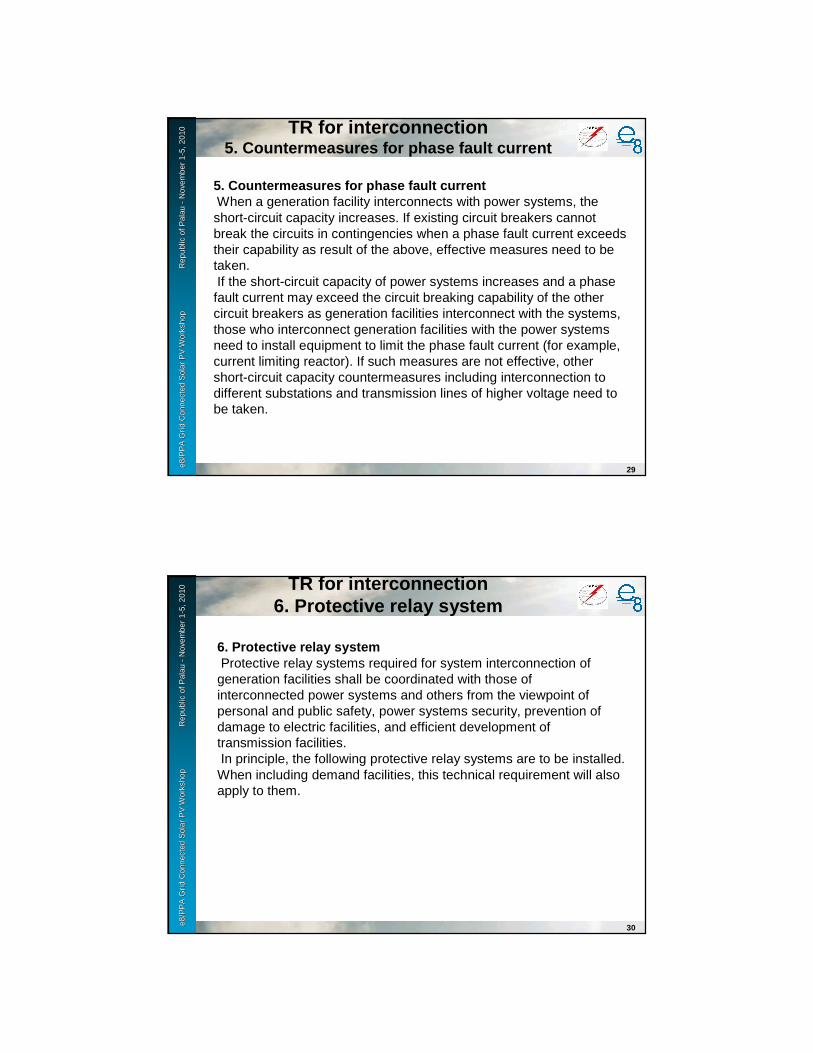
e8 /
PP
A D
SM
Wo
rksh
op
F
iji Is
lan
ds
No
vem
ber
2-6
, 200
9e8
/PP
A G
rid
Con
nect
ed S
olar
PV
Wor
ksho
p
R
epub
le8
/PP
A G
rid
Con
nect
ed S
olar
PV
Wor
ksho
p
R
epub
l ic o
f Pal
au
ic o
f Pal
au --
Nov
embe
r 1
Nov
embe
r 1 --
5, 2
010
5, 2
010 TR for interconnection
5. Countermeasures for phase fault current
29
5. Countermeasures for phase fault currentWhen a generation facility interconnects with power systems, theshort-circuit capacity increases. If existing circuit breakers cannot break the circuits in contingencies when a phase fault current exceeds their capability as result of the above, effective measures need to be taken.If the short-circuit capacity of power systems increases and a phase fault current may exceed the circuit breaking capability of the other circuit breakers as generation facilities interconnect with the systems, those who interconnect generation facilities with the power systems need to install equipment to limit the phase fault current (for example, current limiting reactor). If such measures are not effective, other short-circuit capacity countermeasures including interconnection to different substations and transmission lines of higher voltage need to be taken.
e8 /
PP
A D
SM
Wo
rksh
op
F
iji Is
lan
ds
No
vem
ber
2-6
, 200
9e8
/PP
A G
rid
Con
nect
ed S
olar
PV
Wor
ksho
p
R
epub
le8
/PP
A G
rid
Con
nect
ed S
olar
PV
Wor
ksho
p
R
epub
l ic o
f Pal
au
ic o
f Pal
au --
Nov
embe
r 1
Nov
embe
r 1 --
5, 2
010
5, 2
010 TR for interconnection
6. Protective relay system
30
6. Protective relay systemProtective relay systems required for system interconnection ofgeneration facilities shall be coordinated with those of interconnected power systems and others from the viewpoint of personal and public safety, power systems security, prevention of damage to electric facilities, and efficient development of transmission facilities.In principle, the following protective relay systems are to be installed.When including demand facilities, this technical requirement will also apply to them.

e8 /
PP
A D
SM
Wo
rksh
op
F
iji Is
lan
ds
No
vem
ber
2-6
, 200
9e8
/PP
A G
rid
Con
nect
ed S
olar
PV
Wor
ksho
p
R
epub
le8
/PP
A G
rid
Con
nect
ed S
olar
PV
Wor
ksho
p
R
epub
l ic o
f Pal
au
ic o
f Pal
au --
Nov
embe
r 1
Nov
embe
r 1 --
5, 2
010
5, 2
010 TR for interconnection
6. Protective relay system
31
a. In order to protect power systems from a failure of generationfacilities, protective relays are installed as follows:
- When the voltage of generation facilities increases to an abnormallevel, an over-voltage relay capable of detecting it anddisconnecting generation facilities from power systems within aspecified time period is installed. However, if the generationfacilities are equipped with a protective device for such detectionand protection, its installation can be omitted.
- When the voltage of generation facilities decreases to an abnormallevel, an under-voltage relay capable of detecting it anddisconnecting generation facilities from the power systems withina specified time period is installed. However, if the generationfacilities are equipped with a protective device for such detectionand protection, its installation can be omitted.
e8 /
PP
A D
SM
Wo
rksh
op
F
iji Is
lan
ds
No
vem
ber
2-6
, 200
9e8
/PP
A G
rid
Con
nect
ed S
olar
PV
Wor
ksho
p
R
epub
le8
/PP
A G
rid
Con
nect
ed S
olar
PV
Wor
ksho
p
R
epub
l ic o
f Pal
au
ic o
f Pal
au --
Nov
embe
r 1
Nov
embe
r 1 --
5, 2
010
5, 2
010 TR for interconnection
6. Protective relay system
32
b. In order to protect power systems from a phase fault, protectiverelays are installed as follows:
- When using synchronous generators, a short-circuit directionalrelay capable of detecting any phase fault on the interconnectedsystems and disconnecting the generation facilities from the powersystems concerned is installed; and
- When using induction generators or inverters, an under-voltagerelay capable of detecting any abnormal voltage drop of generatorsand disconnecting them from the interconnected power systems incase of a phase fault in the interconnected systems is installed.

e8 /
PP
A D
SM
Wo
rksh
op
F
iji Is
lan
ds
No
vem
ber
2-6
, 200
9e8
/PP
A G
rid
Con
nect
ed S
olar
PV
Wor
ksho
p
R
epub
le8
/PP
A G
rid
Con
nect
ed S
olar
PV
Wor
ksho
p
R
epub
l ic o
f Pal
au
ic o
f Pal
au --
Nov
embe
r 1
Nov
embe
r 1 --
5, 2
010
5, 2
010 TR for interconnection
6. Protective relay system
33
c. In order to protect power systems from ground faults on them, aground fault over-voltage relay is employed. However, if any ofthe following conditions is satisfied, installation of the relay can beomitted:
- A ground fault of the interconnected systems can be detected by aground fault over-voltage relay installed at the outlet of thegenerator;
- The output of the generation facilities with an inverterinterconnecting with a low voltage line within a site is far smallerthan the site load, and islanding can be detected, stopped anddisconnected quickly by a device with islanding detection function.
e8 /
PP
A D
SM
Wo
rksh
op
F
iji Is
lan
ds
No
vem
ber
2-6
, 200
9e8
/PP
A G
rid
Con
nect
ed S
olar
PV
Wor
ksho
p
R
epub
le8
/PP
A G
rid
Con
nect
ed S
olar
PV
Wor
ksho
p
R
epub
l ic o
f Pal
au
ic o
f Pal
au --
Nov
embe
r 1
Nov
embe
r 1 --
5, 2
010
5, 2
010 TR for interconnection
6. Protective relay system
34
d. If there is a reverse power flow, an over/under frequency relay anda transfer tripping protection or a device with islanding detectionfunction (including more than one active type) which satisfies all ofthe following requirements are installed. An over frequency relaycan be omitted when interconnected with a line for exclusive use:
- It can detect islanding within a required period without fail, takinginto account the system impedance and load situation.
- Its sensitivity does not cause frequent unnecessary parallel out.
- An active signal does not influence power systems substantially.A transfer tripping protection or a device with islanding detection function (including more than one active type) can be omitted only when an over/under frequency relay can detect and protect the islanding quickly and without fail at a wind farm using an induction generator. However, if the above omission requirements cannot be satisfied because of achange in the status of the power systems, those who interconnect the generator with power systems need to install the above devices.
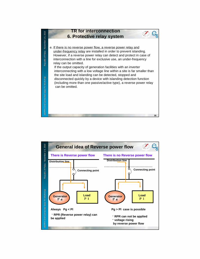
e8 /
PP
A D
SM
Wo
rksh
op
F
iji Is
lan
ds
No
vem
ber
2-6
, 200
9e8
/PP
A G
rid
Con
nect
ed S
olar
PV
Wor
ksho
p
R
epub
le8
/PP
A G
rid
Con
nect
ed S
olar
PV
Wor
ksho
p
R
epub
l ic o
f Pal
au
ic o
f Pal
au --
Nov
embe
r 1
Nov
embe
r 1 --
5, 2
010
5, 2
010 TR for interconnection
6. Protective relay system
35
e. If there is no reverse power flow, a reverse power relay andunder-frequency relay are installed in order to prevent islanding.However, if a reverse power relay can detect and protect in case ofinterconnection with a line for exclusive use, an under-frequencyrelay can be omitted.If the output capacity of generation facilities with an inverterinterconnecting with a low voltage line within a site is far smaller than the site load and islanding can be detected, stopped and disconnected quickly by a device with islanding detection function (including more than one passive/active type), a reverse power relay can be omitted.
e8 /
PP
A D
SM
Wo
rksh
op
F
iji Is
lan
ds
No
vem
ber
2-6
, 200
9e8
/PP
A G
rid
Con
nect
ed S
olar
PV
Wor
ksho
p
R
epub
le8
/PP
A G
rid
Con
nect
ed S
olar
PV
Wor
ksho
p
R
epub
l ic o
f Pal
au
ic o
f Pal
au --
Nov
embe
r 1
Nov
embe
r 1 --
5, 2
010
5, 2
010
There is Reverse power flow
LoadPlPlPlPlGenerator
PgPgPgPg
Always Pg < Pl
・・・・RPR (Reverse power relay) can be applied
Distribution line
Pg > Pl case is possible
・・・・RPR can not be applied・・・・voltage risingby reverse power flow
LoadPlPlPlPlGenerator
PgPgPgPg
There is no Reverse power flow
Distribution line
Connecting point Connecting point
General idea of Reverse power flow

e8 /
PP
A D
SM
Wo
rksh
op
F
iji Is
lan
ds
No
vem
ber
2-6
, 200
9e8
/PP
A G
rid
Con
nect
ed S
olar
PV
Wor
ksho
p
R
epub
le8
/PP
A G
rid
Con
nect
ed S
olar
PV
Wor
ksho
p
R
epub
l ic o
f Pal
au
ic o
f Pal
au --
Nov
embe
r 1
Nov
embe
r 1 --
5, 2
010
5, 2
010
37
Distribution substation
High voltage feeder
Generator
It is necessary for distributed generation to be di sconnected in concert with the fault detection of system.
Without disconnection of distributed generation, ground fault continues even by breaking CB at substation.(Threat of equipment damage and electric shock)
Fault protection of feederwith distributed generation
e8 /
PP
A D
SM
Wo
rksh
op
F
iji Is
lan
ds
No
vem
ber
2-6
, 200
9e8
/PP
A G
rid
Con
nect
ed S
olar
PV
Wor
ksho
p
R
epub
le8
/PP
A G
rid
Con
nect
ed S
olar
PV
Wor
ksho
p
R
epub
l ic o
f Pal
au
ic o
f Pal
au --
Nov
embe
r 1
Nov
embe
r 1 --
5, 2
010
5, 2
010
38
Preventing of islanding
Substation
※※※※PV system is running (islanding operation)
③
③③③③ Threat of electrical shock for worker near crane an d public.
①①①① Crane touches feeder.
①
CB break
②②②② Fault detection, then CB break.
②
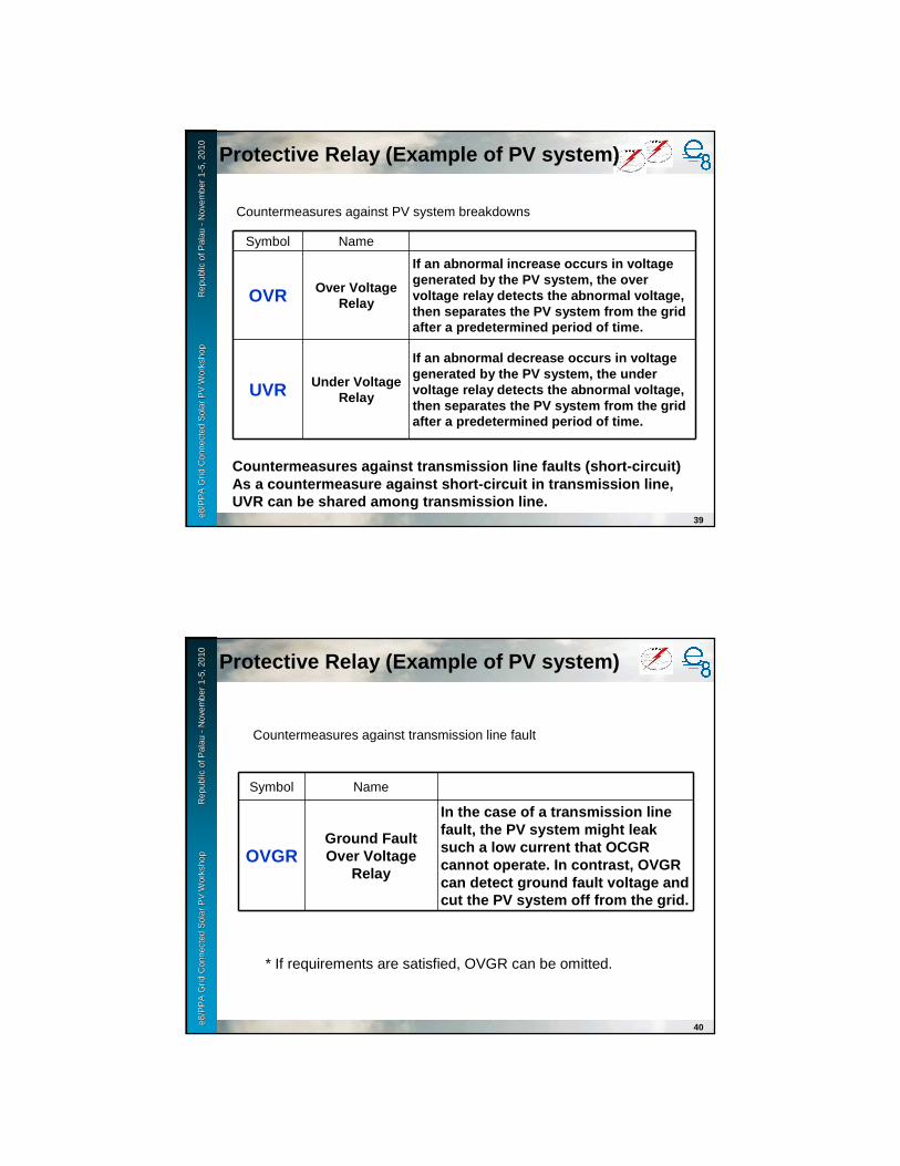
e8 /
PP
A D
SM
Wo
rksh
op
F
iji Is
lan
ds
No
vem
ber
2-6
, 200
9e8
/PP
A G
rid
Con
nect
ed S
olar
PV
Wor
ksho
p
R
epub
le8
/PP
A G
rid
Con
nect
ed S
olar
PV
Wor
ksho
p
R
epub
l ic o
f Pal
au
ic o
f Pal
au --
Nov
embe
r 1
Nov
embe
r 1 --
5, 2
010
5, 2
010
39
Countermeasures against PV system breakdowns
Symbol Name
OVR Over Voltage Relay
If an abnormal increase occurs in voltage generated by the PV system, the over voltage relay detects the abnormal voltage, then separates the PV system from the grid after a predetermined period of time.
UVR Under Voltage Relay
If an abnormal decrease occurs in voltage generated by the PV system, the under voltage relay detects the abnormal voltage, then separates the PV system from the grid after a predetermined period of time.
Countermeasures against transmission line faults (s hort-circuit)As a countermeasure against short-circuit in transm ission line, UVR can be shared among transmission line.
Protective Relay (Example of PV system)
e8 /
PP
A D
SM
Wo
rksh
op
F
iji Is
lan
ds
No
vem
ber
2-6
, 200
9e8
/PP
A G
rid
Con
nect
ed S
olar
PV
Wor
ksho
p
R
epub
le8
/PP
A G
rid
Con
nect
ed S
olar
PV
Wor
ksho
p
R
epub
l ic o
f Pal
au
ic o
f Pal
au --
Nov
embe
r 1
Nov
embe
r 1 --
5, 2
010
5, 2
010
40
Countermeasures against transmission line fault
Symbol Name
OVGRGround Fault Over Voltage
Relay
In the case of a transmission line fault, the PV system might leak such a low current that OCGR cannot operate. In contrast, OVGR can detect ground fault voltage and cut the PV system off from the grid.
* If requirements are satisfied, OVGR can be omitted.
Protective Relay (Example of PV system)
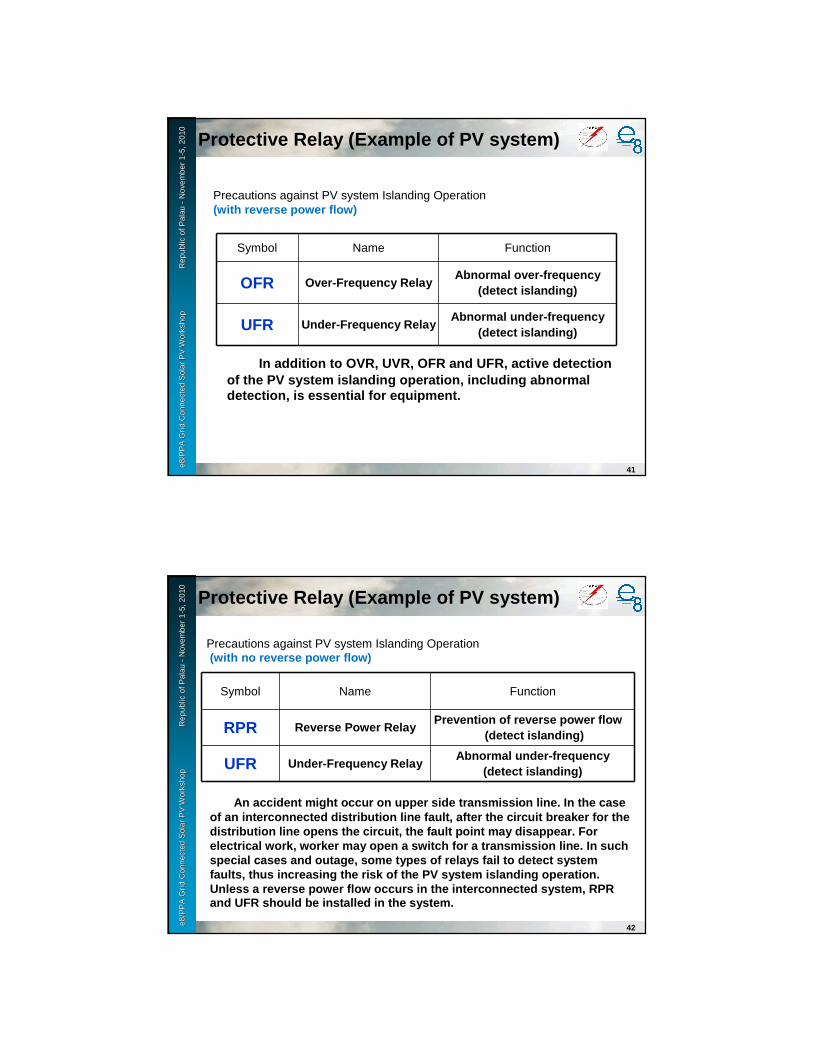
e8 /
PP
A D
SM
Wo
rksh
op
F
iji Is
lan
ds
No
vem
ber
2-6
, 200
9e8
/PP
A G
rid
Con
nect
ed S
olar
PV
Wor
ksho
p
R
epub
le8
/PP
A G
rid
Con
nect
ed S
olar
PV
Wor
ksho
p
R
epub
l ic o
f Pal
au
ic o
f Pal
au --
Nov
embe
r 1
Nov
embe
r 1 --
5, 2
010
5, 2
010
41
Precautions against PV system Islanding Operation (with reverse power flow)
Symbol Name Function
OFR Over-Frequency RelayAbnormal over-frequency
(detect islanding)
UFR Under-Frequency RelayAbnormal under-frequency
(detect islanding)
In addition to OVR, UVR, OFR and UFR, active detect ion of the PV system islanding operation, including abn ormal detection, is essential for equipment.
Protective Relay (Example of PV system)
e8 /
PP
A D
SM
Wo
rksh
op
F
iji Is
lan
ds
No
vem
ber
2-6
, 200
9e8
/PP
A G
rid
Con
nect
ed S
olar
PV
Wor
ksho
p
R
epub
le8
/PP
A G
rid
Con
nect
ed S
olar
PV
Wor
ksho
p
R
epub
l ic o
f Pal
au
ic o
f Pal
au --
Nov
embe
r 1
Nov
embe
r 1 --
5, 2
010
5, 2
010
42
Precautions against PV system Islanding Operation(with no reverse power flow)
Symbol Name Function
RPR Reverse Power RelayPrevention of reverse power flow
(detect islanding)
UFR Under-Frequency RelayAbnormal under-frequency
(detect islanding)
An accident might occur on upper side transmission line. In the case of an interconnected distribution line fault, after the circuit breaker for the distribution line opens the circuit, the fault poin t may disappear. For electrical work, worker may open a switch for a tra nsmission line. In such special cases and outage, some types of relays fail to detect system faults, thus increasing the risk of the PV system i slanding operation. Unless a reverse power flow occurs in the interconn ected system, RPR and UFR should be installed in the system.
Protective Relay (Example of PV system)

e8 /
PP
A D
SM
Wo
rksh
op
F
iji Is
lan
ds
No
vem
ber
2-6
, 200
9e8
/PP
A G
rid
Con
nect
ed S
olar
PV
Wor
ksho
p
R
epub
le8
/PP
A G
rid
Con
nect
ed S
olar
PV
Wor
ksho
p
R
epub
l ic o
f Pal
au
ic o
f Pal
au --
Nov
embe
r 1
Nov
embe
r 1 --
5, 2
010
5, 2
010
43
Type of islanding detection method
→→→→ Use multiple detection to detect absolutely
Protective Relay (Example of PV system)
Active detection
Add disturbance signal from generator to grid continuously
On power outage, detect increased response to disturbance signal
Secure detection, but need several seconds
Passive detection
On power outage, detect phase change of P, Q balance
Possible instant detection
But used as backup of active detection for grid connected generator in high voltage, because of little change at rotating generator
e8 /
PP
A D
SM
Wo
rksh
op
F
iji Is
lan
ds
No
vem
ber
2-6
, 200
9e8
/PP
A G
rid
Con
nect
ed S
olar
PV
Wor
ksho
p
R
epub
le8
/PP
A G
rid
Con
nect
ed S
olar
PV
Wor
ksho
p
R
epub
l ic o
f Pal
au
ic o
f Pal
au --
Nov
embe
r 1
Nov
embe
r 1 --
5, 2
010
5, 2
010
44
Example of protective relay for grid interconnected system (with built-in Power Conditioner)
Example of protective relay for grid interconnectio n system(of external installation type)
UVR (under voltage relay): System short circuit and blackout
OVR (overvoltage relay) : Abnormal overvoltage
OFR (over-frequency relay) : Abnormal over-frequenc y
UFR (under-frequency relay): Accident on higher-vol tage transmission line
OVGR (overvoltage ground relay): Ground fault
RPR (reverse power relay): Prevention of reverse po wer flow
Protective Relaywith built-in power conditioner
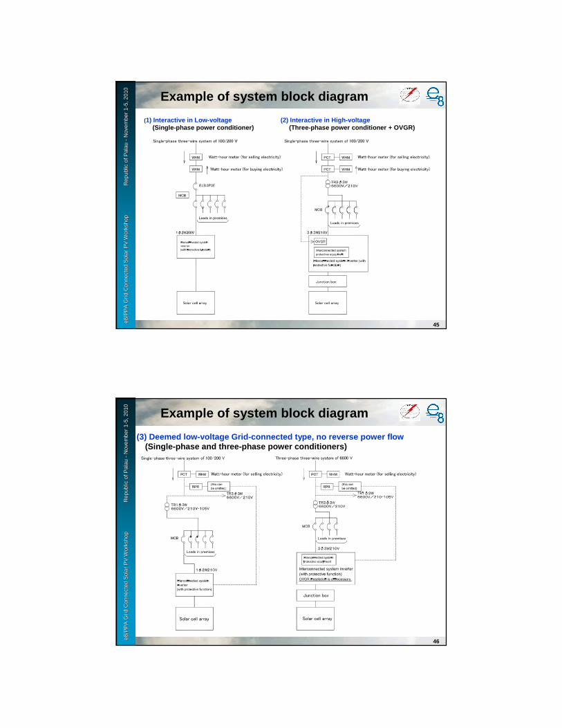
e8 /
PP
A D
SM
Wo
rksh
op
F
iji Is
lan
ds
No
vem
ber
2-6
, 200
9e8
/PP
A G
rid
Con
nect
ed S
olar
PV
Wor
ksho
p
R
epub
le8
/PP
A G
rid
Con
nect
ed S
olar
PV
Wor
ksho
p
R
epub
l ic o
f Pal
au
ic o
f Pal
au --
Nov
embe
r 1
Nov
embe
r 1 --
5, 2
010
5, 2
010
45
(1) Interactive in Low-voltage(Single-phase power conditioner)
(2) Interactive in High-voltage(Three-phase power conditioner + OVGR)
Example of system block diagram
e8 /
PP
A D
SM
Wo
rksh
op
F
iji Is
lan
ds
No
vem
ber
2-6
, 200
9e8
/PP
A G
rid
Con
nect
ed S
olar
PV
Wor
ksho
p
R
epub
le8
/PP
A G
rid
Con
nect
ed S
olar
PV
Wor
ksho
p
R
epub
l ic o
f Pal
au
ic o
f Pal
au --
Nov
embe
r 1
Nov
embe
r 1 --
5, 2
010
5, 2
010
46
(3) Deemed low-voltage Grid-connected type, no reve rse power flow(Single-phase and three-phase power conditioners)
Example of system block diagram

e8 /
PP
A D
SM
Wo
rksh
op
F
iji Is
lan
ds
No
vem
ber
2-6
, 200
9e8
/PP
A G
rid
Con
nect
ed S
olar
PV
Wor
ksho
p
R
epub
le8
/PP
A G
rid
Con
nect
ed S
olar
PV
Wor
ksho
p
R
epub
l ic o
f Pal
au
ic o
f Pal
au --
Nov
embe
r 1
Nov
embe
r 1 --
5, 2
010
5, 2
010 TR for interconnection
7. Neutral point grounding system8. Automatic load shedding device
47
7. Neutral point grounding systemWhen necessary for grounding at a neutral point of generation facilities or interconnection facilities on a high voltage side, those who interconnect generation facilities with high voltage distribution systems consult with power company and adopt a grounding system designated by power company.
8. Automatic load shedding deviceWhen there is a possibility of overloading the interconnected distribution lines at the time of a loss of generation and so forth, those who interconnect the generation facilities with power systems need to take measures that automatically limit the load.
e8 /
PP
A D
SM
Wo
rksh
op
F
iji Is
lan
ds
No
vem
ber
2-6
, 200
9e8
/PP
A G
rid
Con
nect
ed S
olar
PV
Wor
ksho
p
R
epub
le8
/PP
A G
rid
Con
nect
ed S
olar
PV
Wor
ksho
p
R
epub
l ic o
f Pal
au
ic o
f Pal
au --
Nov
embe
r 1
Nov
embe
r 1 --
5, 2
010
5, 2
010 TR for interconnection
9. Device to confirm no-voltage on distribution lin e
48
9. Device to confirm no-voltage on distribution lin eA device designed to confirm no voltage on distribution lines isinstalled at the outlet of distribution lines from a substation for distribution in order to prevent faults at the time of automaticreclosing. However, such a device can be omitted if either of the following items is satisfied:
(1) The installer of the generation facility does not require automaticreclosing because of connection to a line for exclusive use
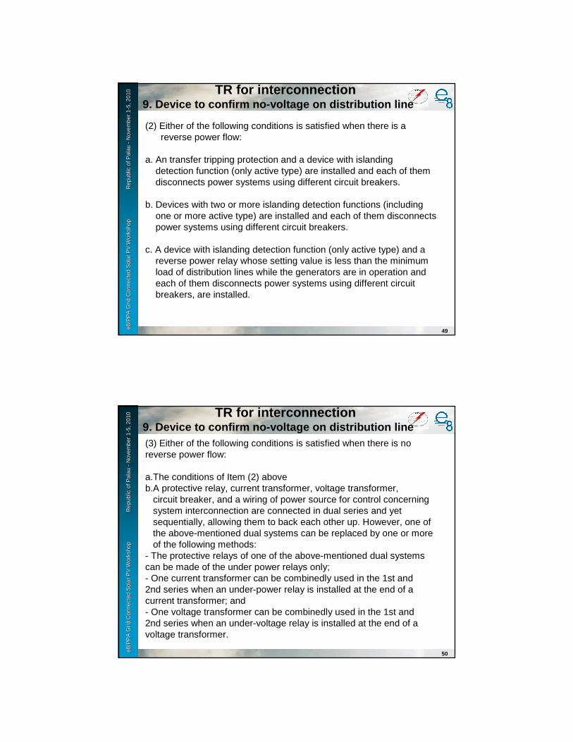
e8 /
PP
A D
SM
Wo
rksh
op
F
iji Is
lan
ds
No
vem
ber
2-6
, 200
9e8
/PP
A G
rid
Con
nect
ed S
olar
PV
Wor
ksho
p
R
epub
le8
/PP
A G
rid
Con
nect
ed S
olar
PV
Wor
ksho
p
R
epub
l ic o
f Pal
au
ic o
f Pal
au --
Nov
embe
r 1
Nov
embe
r 1 --
5, 2
010
5, 2
010
49
(2) Either of the following conditions is satisfied when there is areverse power flow:
a. An transfer tripping protection and a device with islandingdetection function (only active type) are installed and each of themdisconnects power systems using different circuit breakers.
b. Devices with two or more islanding detection functions (includingone or more active type) are installed and each of them disconnectspower systems using different circuit breakers.
c. A device with islanding detection function (only active type) and areverse power relay whose setting value is less than the minimumload of distribution lines while the generators are in operation andeach of them disconnects power systems using different circuitbreakers, are installed.
TR for interconnection9. Device to confirm no-voltage on distribution lin e
e8 /
PP
A D
SM
Wo
rksh
op
F
iji Is
lan
ds
No
vem
ber
2-6
, 200
9e8
/PP
A G
rid
Con
nect
ed S
olar
PV
Wor
ksho
p
R
epub
le8
/PP
A G
rid
Con
nect
ed S
olar
PV
Wor
ksho
p
R
epub
l ic o
f Pal
au
ic o
f Pal
au --
Nov
embe
r 1
Nov
embe
r 1 --
5, 2
010
5, 2
010
50
(3) Either of the following conditions is satisfied when there is noreverse power flow:
a.The conditions of Item (2) aboveb.A protective relay, current transformer, voltage transformer,
circuit breaker, and a wiring of power source for control concerningsystem interconnection are connected in dual series and yetsequentially, allowing them to back each other up. However, one ofthe above-mentioned dual systems can be replaced by one or moreof the following methods:
- The protective relays of one of the above-mentioned dual systemscan be made of the under power relays only;- One current transformer can be combinedly used in the 1st and2nd series when an under-power relay is installed at the end of acurrent transformer; and- One voltage transformer can be combinedly used in the 1st and2nd series when an under-voltage relay is installed at the end of avoltage transformer.
TR for interconnection9. Device to confirm no-voltage on distribution lin e
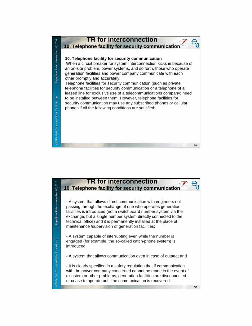
e8 /
PP
A D
SM
Wo
rksh
op
F
iji Is
lan
ds
No
vem
ber
2-6
, 200
9e8
/PP
A G
rid
Con
nect
ed S
olar
PV
Wor
ksho
p
R
epub
le8
/PP
A G
rid
Con
nect
ed S
olar
PV
Wor
ksho
p
R
epub
l ic o
f Pal
au
ic o
f Pal
au --
Nov
embe
r 1
Nov
embe
r 1 --
5, 2
010
5, 2
010 TR for interconnection
10. Telephone facility for security communication
51
10. Telephone facility for security communicationWhen a circuit breaker for system interconnection kicks in because of an on-site problem, power systems, and so forth, those who operate generation facilities and power company communicate with each other promptly and accurately.Telephone facilities for security communication (such as privatetelephone facilities for security communication or a telephone of a leased line for exclusive use of a telecommunications company) need to be installed between them. However, telephone facilities for security communication may use any subscribed phones or cellularphones if all the following conditions are satisfied:
e8 /
PP
A D
SM
Wo
rksh
op
F
iji Is
lan
ds
No
vem
ber
2-6
, 200
9e8
/PP
A G
rid
Con
nect
ed S
olar
PV
Wor
ksho
p
R
epub
le8
/PP
A G
rid
Con
nect
ed S
olar
PV
Wor
ksho
p
R
epub
l ic o
f Pal
au
ic o
f Pal
au --
Nov
embe
r 1
Nov
embe
r 1 --
5, 2
010
5, 2
010
52
- A system that allows direct communication with engineers notpassing through the exchange of one who operates generationfacilities is introduced (not a switchboard number system via theexchange, but a single number system directly connected to thetechnical office) and it is permanently installed at the place ofmaintenance /supervision of generation facilities;
- A system capable of interrupting even while the number isengaged (for example, the so-called catch-phone system) isintroduced;
- A system that allows communication even in case of outage; and
- It is clearly specified in a safety regulation that if communicationwith the power company concerned cannot be made in the event ofdisasters or other problems, generation facilities are disconnectedor cease to operate until the communication is recovered.
TR for interconnection10. Telephone facility for security communication

e8 /
PP
A D
SM
Wo
rksh
op
F
iji Is
lan
ds
No
vem
ber
2-6
, 200
9e8
/PP
A G
rid
Con
nect
ed S
olar
PV
Wor
ksho
p
R
epub
le8
/PP
A G
rid
Con
nect
ed S
olar
PV
Wor
ksho
p
R
epub
l ic o
f Pal
au
ic o
f Pal
au --
Nov
embe
r 1
Nov
embe
r 1 --
5, 2
010
5, 2
010
53
11. Prevention of reverse power flow through main t ransformerAs a power flow from a high voltage side to a special high voltage sidethrough a main transformer for distribution (hereinafter referred to as “areverse power flow through a main transformer”) may cause some problems in voltage management and protection coordination of distribution systems, it is important to prevent such a power flow through a main transformer.To make sure that a generation facility with a reverse power flow will not always cause such a reverse power flow through a main transformer, the occurrence of the flow is judged based on generation output and load patterns when interconnections are examined. If it is deemed that a reverse power flow through a main transformer is likely to occur, measures to control generators and similar actions will be taken.
TR for interconnection11. Prevention of reverse power flow
through main transformer


1
Day Day 44


Grid Connected Solar PV WorkshopPalau
November 1-5,2010
GuidlineGuidline of constructionof construction and and mantenancemantenance
e8 /
PP
A D
SM
Wo
rksh
op
F
iji Is
lan
ds
No
vem
ber
2-6
, 200
9e8
/PP
A G
rid
Con
nect
ed S
olar
PV
Wor
ksho
p
Rep
ublic
e8
/PP
A G
rid
Con
nect
ed S
olar
PV
Wor
ksho
p
Rep
ublic
of
Pal
auof
Pal
au--
Nov
embe
r 1
Nov
embe
r 1 --
5, 2
010
5, 2
010
2
IndexIndex
1 ---- System Construction Design 2222 ---- Design and Construction Flow3333 ---- Construction Management Points 4444 ---- Pricing Guidelines5555 ---- Field Inspection Items6666 ---- Maintenance7777 ---- Economical Effects

e8 /
PP
A D
SM
Wo
rksh
op
F
iji Is
lan
ds
No
vem
ber
2-6
, 200
9e8
/PP
A G
rid
Con
nect
ed S
olar
PV
Wor
ksho
p
Rep
ublic
e8
/PP
A G
rid
Con
nect
ed S
olar
PV
Wor
ksho
p
Rep
ublic
of
Pal
auof
Pal
au--
Nov
embe
r 1
Nov
embe
r 1 --
5, 2
010
5, 2
010
3
Laws and regulations
Piping and wiring sizes
Waterproof construction
Earthing MaintenancePiping and
wiring routesGrid-
ConnectionFoundation work
Support Structure construction
Electrical work
System
Guidelines
Architectural work
Architectural Code
-Voltage-Protection Coordination
- Voltage drops - Scaffolding- Use of existing
routes
- Lead-in cables
- Equipment sheds
- Existing earthingtype
- Safety regulations
- Wind pressure calculation
- Waterproof roofs and rooftops
- Wind pressure calculation
- Electromagnetic interference
� Compliance : Design based on laws and regulations
� Easy construction : Design that facilitates safe construction, and shortens construction term
�Low cost construction : Design that reduces material and labor expenses
Wiring rules
1.System Construction Design1.System Construction Design
e8 /
PP
A D
SM
Wo
rksh
op
F
iji Is
lan
ds
No
vem
ber
2-6
, 200
9e8
/PP
A G
rid
Con
nect
ed S
olar
PV
Wor
ksho
p
Rep
ublic
e8
/PP
A G
rid
Con
nect
ed S
olar
PV
Wor
ksho
p
Rep
ublic
of
Pal
auof
Pal
au--
Nov
embe
r 1
Nov
embe
r 1 --
5, 2
010
5, 2
010
4
Site investigation
Design ConstructionTrial operation
and Adjustment
Completion
- Installation AreasOn ground or roofLength, width and azimuth
-Roof typeDeck roofs or sloping roofs
Roofing materials, Waterproof types
- ObstaclesPoles, buildings, antennas, mountains, trees (and other obstacles that cast shadows on PV Arrays.)
- Piping RoutesExisting piping routes and wiring diagrams
- Equipments Installation locationsSwitchboards, control boards, Power Conditioners, instrumentation and display
- Routes for Carrying inCrane or Wrecker installation location and temporary placement space
- DiagramSkeleton diagram from electric power company lead-in cable to interconnection point
- Contract with electric power companyPrice of buying and selling power
- Foundation work (rooftop)
- Electric connection work
- Visual InspectionCracks, damage of devices
- Insulation Resistance testCable insulation resistance
- Open-Circuit voltage testVoltage measurement of each series of PV modules
- Setting of Power Conditioner protective relays
Setting based on discussion with the electric power company
- Adjustment of measuring instruments
Deviation from Power Conditioner indicating values
- Adjustment of indicationDiscrepancy between measurements and indications
- Electrical piping and wiring
- Devices Installation
- PV modules Installation
- Carrying in
- PV module Support Structure Earthing
2. 12. 1 Design and Construction Flow

e8 /
PP
A D
SM
Wo
rksh
op
F
iji Is
lan
ds
No
vem
ber
2-6
, 200
9e8
/PP
A G
rid
Con
nect
ed S
olar
PV
Wor
ksho
p
Rep
ublic
e8
/PP
A G
rid
Con
nect
ed S
olar
PV
Wor
ksho
p
Rep
ublic
of
Pal
auof
Pal
au--
Nov
embe
r 1
Nov
embe
r 1 --
5, 2
010
5, 2
010
5
Area of PV array installation site
Investigation the area of installation site
East-west width and north-south length are measured.
Environment Verification the influence of shadows cast by buildings, tall trees and other obstacles.
Verification possible damage due to weather like salt damage, snow, wind or other weather conditions.
Azimuth Verification the influence of shadows cast by buildings, tall trees and other obstacles.
Verification possible damage due to weather like salt damage, snow, wind or other weather conditions.
Environmental Survey
Azimuth and Angle
2.2. 2 Site investigation Guideline (1)
e8 /
PP
A D
SM
Wo
rksh
op
F
iji Is
lan
ds
No
vem
ber
2-6
, 200
9e8
/PP
A G
rid
Con
nect
ed S
olar
PV
Wor
ksho
p
Rep
ublic
e8
/PP
A G
rid
Con
nect
ed S
olar
PV
Wor
ksho
p
Rep
ublic
of
Pal
auof
Pal
au--
Nov
embe
r 1
Nov
embe
r 1 --
5, 2
010
5, 2
010
6
Condition of Electric Power Transmission
Verification the type of power source system and determination the type of interconnection.
Staff verifies voltage fluctuations and frequency variations.
Recognition of Regulations and Standards
Approval to the System for Interconnection
Discussion with the electric
power company
Equipments Installation Site Installation Site Survey
Junction boxes, centralized control boards, interconnection switchboards, transformers
Local Ordinances
2.2. 2 Site investigation Guideline (2)
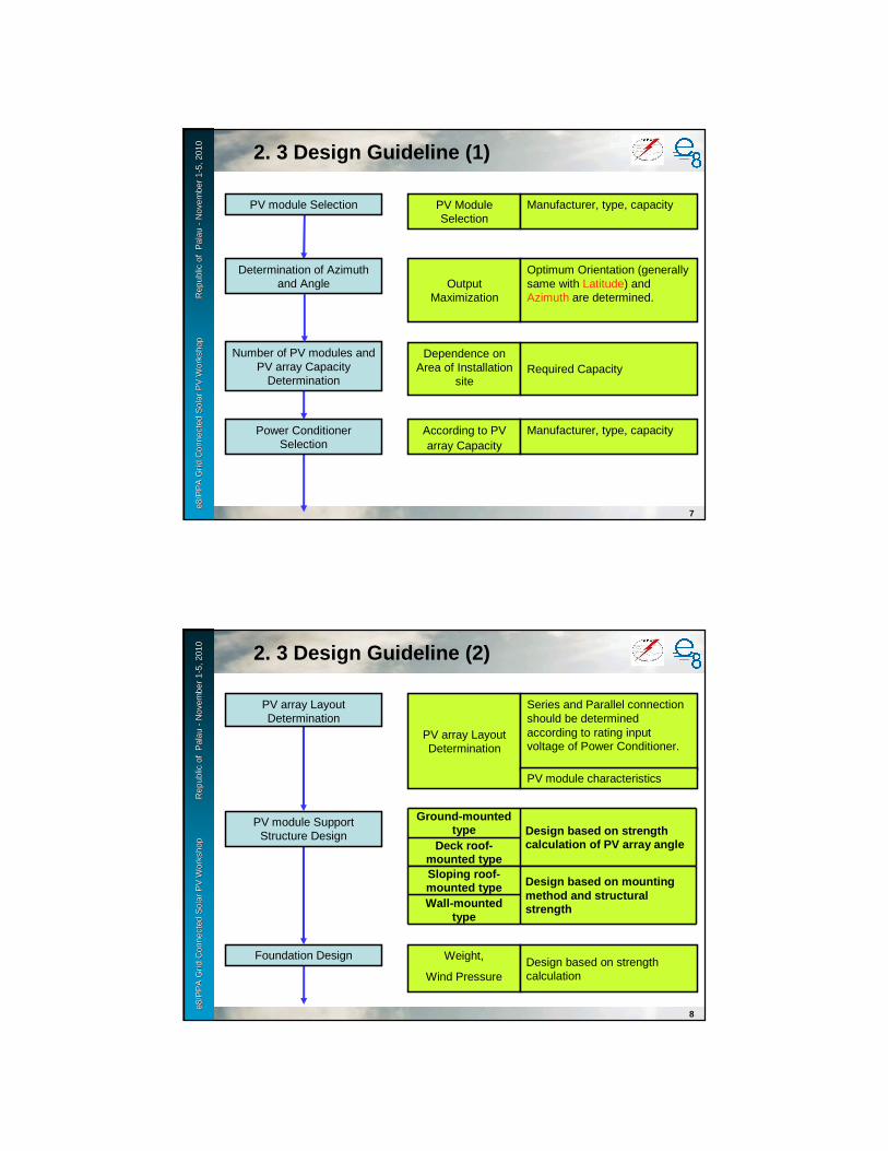
e8 /
PP
A D
SM
Wo
rksh
op
F
iji Is
lan
ds
No
vem
ber
2-6
, 200
9e8
/PP
A G
rid
Con
nect
ed S
olar
PV
Wor
ksho
p
Rep
ublic
e8
/PP
A G
rid
Con
nect
ed S
olar
PV
Wor
ksho
p
Rep
ublic
of
Pal
auof
Pal
au--
Nov
embe
r 1
Nov
embe
r 1 --
5, 2
010
5, 2
010
7
PV module Selection PV Module Selection
Manufacturer, type, capacity
Number of PV modules and PV array Capacity
Determination
Dependence on Area of Installation
siteRequired Capacity
Power Conditioner Selection
According to PV array Capacity
Manufacturer, type, capacity
Determination of Azimuth and Angle Output
Maximization
Optimum Orientation (generally same with Latitude) and Azimuth are determined.
2.2. 3 Design Guideline (1)
e8 /
PP
A D
SM
Wo
rksh
op
F
iji Is
lan
ds
No
vem
ber
2-6
, 200
9e8
/PP
A G
rid
Con
nect
ed S
olar
PV
Wor
ksho
p
Rep
ublic
e8
/PP
A G
rid
Con
nect
ed S
olar
PV
Wor
ksho
p
Rep
ublic
of
Pal
auof
Pal
au--
Nov
embe
r 1
Nov
embe
r 1 --
5, 2
010
5, 2
010
8
Foundation Design Weight,
Wind PressureDesign based on strength calculation
PV module Support Structure Design
Ground-mounted type Design based on strength
calculation of PV array angleDeck roof-mounted typeSloping roof-mounted type Design based on mounting
method and structural strengthWall-mounted
type
PV array Layout Determination
PV array Layout Determination
Series and Parallel connection should be determined according to rating input voltage of Power Conditioner.
PV module characteristics
2.2. 3 Design Guideline (2)

e8 /
PP
A D
SM
Wo
rksh
op
F
iji Is
lan
ds
No
vem
ber
2-6
, 200
9e8
/PP
A G
rid
Con
nect
ed S
olar
PV
Wor
ksho
p
Rep
ublic
e8
/PP
A G
rid
Con
nect
ed S
olar
PV
Wor
ksho
p
Rep
ublic
of
Pal
auof
Pal
au--
Nov
embe
r 1
Nov
embe
r 1 --
5, 2
010
5, 2
010
9
Equipments selection Indoor type or Outdoor type
should be selected.
Provision of watercourses for carrying away rainwater
Interconnection circuit breaker selection
Power conditioner protection
Selection based on power conditioner capacity
Selection of protective relays
Protection from accidents of
grid
Selection based on electric powerconditions, rules and standards
Selection of piping and wiring between devices
Minimization of wiring paths
Selection based on allowable current, voltage drops, standards and rules
2.2. 3 Design Guideline (3)
e8 /
PP
A D
SM
Wo
rksh
op
F
iji Is
lan
ds
No
vem
ber
2-6
, 200
9e8
/PP
A G
rid
Con
nect
ed S
olar
PV
Wor
ksho
p
Rep
ublic
e8
/PP
A G
rid
Con
nect
ed S
olar
PV
Wor
ksho
p
Rep
ublic
of
Pal
auof
Pal
au--
Nov
embe
r 1
Nov
embe
r 1 --
5, 2
010
5, 2
010
10
PVmodules
Power conditioner
Charge and discharge controller
Storage batteries
Electric power company
Offices and/or factories
Selling Selling electricityelectricity
Buying electricityBuying electricity
Applicable to disaster prevention (system includes storage batteries.)
* Capacity of storage batteries is determined according to setting of load amperage, load types and operation time.
Display system
2.2. 4 Example systems4 Example systems
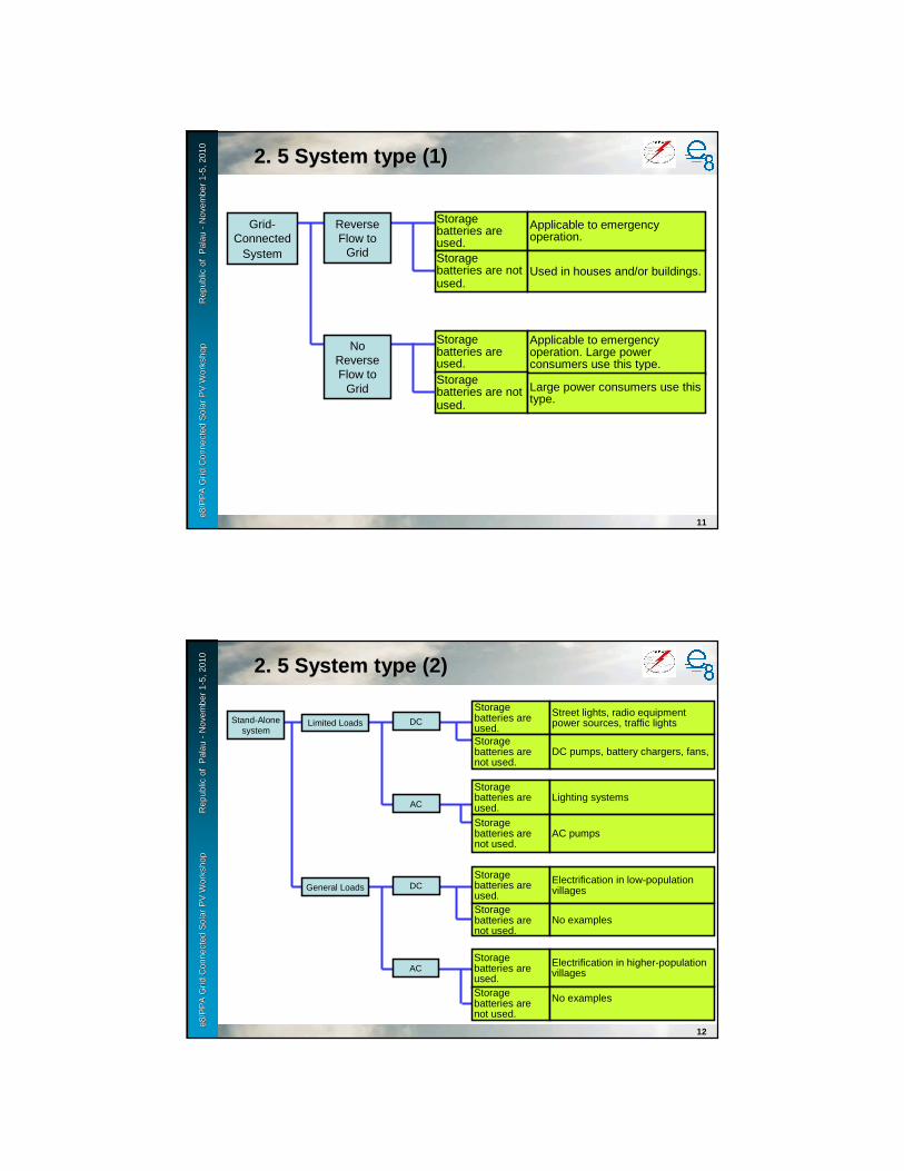
e8 /
PP
A D
SM
Wo
rksh
op
F
iji Is
lan
ds
No
vem
ber
2-6
, 200
9e8
/PP
A G
rid
Con
nect
ed S
olar
PV
Wor
ksho
p
Rep
ublic
e8
/PP
A G
rid
Con
nect
ed S
olar
PV
Wor
ksho
p
Rep
ublic
of
Pal
auof
Pal
au--
Nov
embe
r 1
Nov
embe
r 1 --
5, 2
010
5, 2
010
11
Grid-Connected
System
Reverse Flow to
Grid
Storage batteries are used.
Applicable to emergency operation.
Storage batteries are not used.
Used in houses and/or buildings.
Storage batteries are used.
Applicable to emergency operation. Large power consumers use this type.
Storage batteries are not used.
Large power consumers use this type.
No Reverse Flow to
Grid
2.2. 5 System type (1)5 System type (1)
e8 /
PP
A D
SM
Wo
rksh
op
F
iji Is
lan
ds
No
vem
ber
2-6
, 200
9e8
/PP
A G
rid
Con
nect
ed S
olar
PV
Wor
ksho
p
Rep
ublic
e8
/PP
A G
rid
Con
nect
ed S
olar
PV
Wor
ksho
p
Rep
ublic
of
Pal
auof
Pal
au--
Nov
embe
r 1
Nov
embe
r 1 --
5, 2
010
5, 2
010
12
Stand-Alone system
Storage batteries are used.
Street lights, radio equipment power sources, traffic lightsLimited Loads DC
AC
Storage batteries are not used.
DC pumps, battery chargers, fans,
Storage batteries are used.
Lighting systems
Storage batteries are not used.
AC pumps
Storage batteries are used.
Electrification in low-population villagesGeneral Loads
Storage batteries are not used.
No examples
DC
ACStorage batteries are used.
Electrification in higher-population villages
Storage batteries are not used.
No examples
2.2. 5 System type (2)5 System type (2)

e8 /
PP
A D
SM
Wo
rksh
op
F
iji Is
lan
ds
No
vem
ber
2-6
, 200
9e8
/PP
A G
rid
Con
nect
ed S
olar
PV
Wor
ksho
p
Rep
ublic
e8
/PP
A G
rid
Con
nect
ed S
olar
PV
Wor
ksho
p
Rep
ublic
of
Pal
auof
Pal
au--
Nov
embe
r 1
Nov
embe
r 1 --
5, 2
010
5, 2
010
13
Power Conditioners are classified into three:
(1) Low-voltage interconnected system (single-phase power conditioner)Interconnected with low-voltage distribution lines that supply power to general houses.Incoming voltage : Single-phase three-wire system of 100/200 VInterconnected point : Single-phase three-wire system of 100/200 V
(2) High-voltage interconnected type (three-phase power conditioner + OVGR)Interconnected with high-voltage distribution lines that supply power to factories and other high demanders.Incoming voltage : Three-phase three-wire system of 6600 VInterconnected point : Three-phase three-wire system of 200 V
(3) Deemed low-voltage interconnected types (single-phase and three-phase power conditioners)
Despite the high incoming voltage, PV system output is much less than the contract demand.Incoming voltage : Three-phase three-wire system of 6600 VInterconnected point : Three-phase three-wire system of 200 V
: Single-phase three-wire system of 100/200 V
2.2. 6 Power conditioner selection (1)6 Power conditioner selection (1)
e8 /
PP
A D
SM
Wo
rksh
op
F
iji Is
lan
ds
No
vem
ber
2-6
, 200
9e8
/PP
A G
rid
Con
nect
ed S
olar
PV
Wor
ksho
p
Rep
ublic
e8
/PP
A G
rid
Con
nect
ed S
olar
PV
Wor
ksho
p
Rep
ublic
of
Pal
auof
Pal
au--
Nov
embe
r 1
Nov
embe
r 1 --
5, 2
010
5, 2
010
14
Power Conditioner installation space<Operating conditions> Ambient temperature : -5 ºC to + 40 ºC (normal operation, standby)
Relative humidity : 30% to 90%Installation site : Indoor
Outdoor (enabled by accommodating in a cubicle.)
To provide spaces for inspection and heat dissipation, it is necessary to place the inverter off the walls and the top as shown below.It is possible to change side walls to parallel boards.<Example>
Distance to top: 500 mm or more
Distance to front: 1,000 mm or more Distance to back: 100 mm or more
[Side View]Dimensions differ depending on the power conditioner manufacturer.<Reference> Specifications of indoor inverters of 10 kW to 30 kW (900 W x 1875 H x 700 D)
Weight: 230 kg (10 kW)290 kg (20 kW)370 kg (30 kW)
* The above example is a power conditioner of the standard system (of interconnection type).
It is recommended that the power conditioner should be placed outdoors or in an electric-generation room because of the harmonic noise level.
2.2. 6 Power conditioner selection (2)6 Power conditioner selection (2)

e8 /
PP
A D
SM
Wo
rksh
op
F
iji Is
lan
ds
No
vem
ber
2-6
, 200
9e8
/PP
A G
rid
Con
nect
ed S
olar
PV
Wor
ksho
p
Rep
ublic
e8
/PP
A G
rid
Con
nect
ed S
olar
PV
Wor
ksho
p
Rep
ublic
of
Pal
auof
Pal
au--
Nov
embe
r 1
Nov
embe
r 1 --
5, 2
010
5, 2
010 2.2. 7 Equipment type7 Equipment type
e8 /
PP
A D
SM
Wo
rksh
op
F
iji Is
lan
ds
No
vem
ber
2-6
, 200
9e8
/PP
A G
rid
Con
nect
ed S
olar
PV
Wor
ksho
p
Rep
ublic
e8
/PP
A G
rid
Con
nect
ed S
olar
PV
Wor
ksho
p
Rep
ublic
of
Pal
auof
Pal
au--
Nov
embe
r 1
Nov
embe
r 1 --
5, 2
010
5, 2
010
16
Site investigation
Installation site confirmation
Roof-mounted Confirm that a lift to the roof is provided.
Wall-mountedDetermine whether or not the provision of scaffolding and a man lift truck is necessary.
Ground-mounted Recognize the work space for construction equipment (s).
Verification of installation conditions
Deck roof Check waterproof type.
Folded plate roof Check folded plate fixture type.
Sloping roof Verify inclination and anti-slip properties
Confirmation of interconnected point
Circuit breaker for interconnected system
Confirm an extended space.
High-voltage protection relay
If circuit break is needed for relay installation, confirm the circuit break point.
Verification of piping and wiring routes
Route checkDetermine whether or not the provision of scaffolding and worker lift truck is necessary.
Determine whether the existing route can be used.
Carrying in route check
Carrying in route check
Verify working location of construction equipment (wrecker).
3.3. Construction Management Points (1)

e8 /
PP
A D
SM
Wo
rksh
op
F
iji Is
lan
ds
No
vem
ber
2-6
, 200
9e8
/PP
A G
rid
Con
nect
ed S
olar
PV
Wor
ksho
p
Rep
ublic
e8
/PP
A G
rid
Con
nect
ed S
olar
PV
Wor
ksho
p
Rep
ublic
of
Pal
auof
Pal
au--
Nov
embe
r 1
Nov
embe
r 1 --
5, 2
010
5, 2
010
17
Getting there
Marking
Temporary office
Provide an on-site office.
Determine whether or not the provision of scaffolding and worker lift truck is necessary.
Temporary yard
Provide a materials yard.
Provide a yard close to the site.
Marking Marking based on reference line
Check the drawing.Confirm shadows.
Carrying in Crane placement
Placement of crane at predetermined location
Verify hoisting loads and construction equipment.Confirm the operating, hanging and signaling workers.Prohibit admittance to work area.Inspect the hoisting accessory.
Rooftop care Prevention with panel
Install to prevent the wind from blowing PV cell modules.
Provision of access made by planks.
Bind planks.
Craning Craning the PV module support structure and PV modules
Confirm the stability of the crane and load at a lift of 30 cm above the ground.
Do not enter beneath loads.
3.3. Construction Management Points (2)
e8 /
PP
A D
SM
Wo
rksh
op
F
iji Is
lan
ds
No
vem
ber
2-6
, 200
9e8
/PP
A G
rid
Con
nect
ed S
olar
PV
Wor
ksho
p
Rep
ublic
e8
/PP
A G
rid
Con
nect
ed S
olar
PV
Wor
ksho
p
Rep
ublic
of
Pal
auof
Pal
au--
Nov
embe
r 1
Nov
embe
r 1 --
5, 2
010
5, 2
010
18
Fixture mounting
Mount fixture. Mount fixtures to marking.
Support StructureAssembling
Assemble the Support Structure
With stainless bolts, mount the Support Structure to fixture.
Confirm that the horizontal and vertical those should be.
PV module Support
Structure Installation
PV module Installation
Mounting PV modules to the Support Structure
Carefully handle the PV module, and mount it to the fixture without damage.
Align modules flush with longitudinal and lateral lines.
During mounting, workers shall communicate with one another.
PV modules Installation
3.3. Construction Management Points (3)

e8 /
PP
A D
SM
Wo
rksh
op
F
iji Is
lan
ds
No
vem
ber
2-6
, 200
9e8
/PP
A G
rid
Con
nect
ed S
olar
PV
Wor
ksho
p
Rep
ublic
e8
/PP
A G
rid
Con
nect
ed S
olar
PV
Wor
ksho
p
Rep
ublic
of
Pal
auof
Pal
au--
Nov
embe
r 1
Nov
embe
r 1 --
5, 2
010
5, 2
010
19
Wiring between each PV modules
Wiring of connector cables between each modules
Confirm that the circuit and system are constructed according to the drawings.
Connection between each PV modules
Wiring of connectors between each modules
Confirm the polarity and system of the cable connectors, and connect them.Confirm that the cable plug is securely connected.After the connection between modules, cover terminals with insulation tape to prevent short-circuits.
Equipment installation
Installation Power Conditioner and Interconnection board
Install according to the drawing.Install so that devices cannot cast shadows on each other.Be careful not to damage the casing.
Laying electrical conduits
Laying electrical conduits
Using hangers, saddles and other metal supports, mount conduits.Mount according to the drawing.
Laying cable rack With metal supports, mount the cable rack.Mount according to the drawing.
Laying cable Laying cable Select line types and distance, according to design drawing.Be careful not to damage the covering of the cable.
Getting cables straight Fix cables to rack.
Connecting wires
Connection to switchboards
Use of appropriate terminal lugs
Electrical Piping and Wiring work
3.3. Construction Management Points (4)Construction Management Points (4)
e8 /
PP
A D
SM
Wo
rksh
op
F
iji Is
lan
ds
No
vem
ber
2-6
, 200
9e8
/PP
A G
rid
Con
nect
ed S
olar
PV
Wor
ksho
p
Rep
ublic
e8
/PP
A G
rid
Con
nect
ed S
olar
PV
Wor
ksho
p
Rep
ublic
of
Pal
auof
Pal
au--
Nov
embe
r 1
Nov
embe
r 1 --
5, 2
010
5, 2
010
20
Breaker, OVGR and extension
Outage With electroscope, confirm an outage.
Circuit breaker and OVGR extension
Earth units. Earth all devices.
ZPD and OVGR are mounted.
ZPD and OVGR are mounted in place.
Circuit breaker extension
Outage With an electroscope, confirm outage.
Mount breaker. Mount circuit breaker in place.
Restoration Check inside of cubicle.
Outage work
(altering switchboards)
InspectionVisual Inspection
Visual Inspection of Equipment s
Confirm that devices are free from cracks.
Open-Voltage Measurement
Measurement of voltage per system with tester
Measure the voltage of each circuit in inverter, and record.
Insulation resistance measurement
Measurement of insulation resistance with tester
Check batteries.Verify the connections to the earthingterminals.
PV array circuit Measure voltage across earthingterminals, and record.
Voltage across Power conditioner and Interconnection board
Measure voltage across batteries and across lines, and record it.
Voltage across Interconnection board and interconnected point
Measure voltage between earth and batteries and across lines, and record it.
3.3. Construction Management Points (5)Construction Management Points (5)
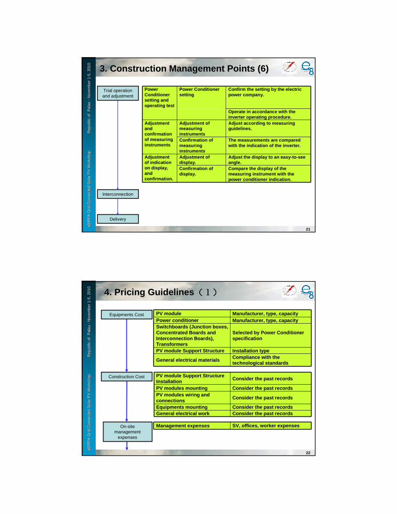
e8 /
PP
A D
SM
Wo
rksh
op
F
iji Is
lan
ds
No
vem
ber
2-6
, 200
9e8
/PP
A G
rid
Con
nect
ed S
olar
PV
Wor
ksho
p
Rep
ublic
e8
/PP
A G
rid
Con
nect
ed S
olar
PV
Wor
ksho
p
Rep
ublic
of
Pal
auof
Pal
au--
Nov
embe
r 1
Nov
embe
r 1 --
5, 2
010
5, 2
010
21
Trial operation and adjustment
Interconnection
Delivery
Power Conditioner setting and operating test
Power Conditioner setting
Confirm the setting by the electric power company.
Operate in accordance with the inverter operating procedure.
Adjustment and confirmation of measuring instruments
Adjustment of measuring instruments
Adjust according to measuring guidelines.
Confirmation of measuring instruments
The measurements are compared with the indication of the inverter.
Adjustment of indication on display, and confirmation.
Adjustment of display.
Adjust the display to an easy-to-see angle.
Confirmation of display.
Compare the display of the measuring instrument with the power conditioner indication.
3.3. Construction Management Points (6)Construction Management Points (6)
e8 /
PP
A D
SM
Wo
rksh
op
F
iji Is
lan
ds
No
vem
ber
2-6
, 200
9e8
/PP
A G
rid
Con
nect
ed S
olar
PV
Wor
ksho
p
Rep
ublic
e8
/PP
A G
rid
Con
nect
ed S
olar
PV
Wor
ksho
p
Rep
ublic
of
Pal
auof
Pal
au--
Nov
embe
r 1
Nov
embe
r 1 --
5, 2
010
5, 2
010
22
Equipments Cost
Construction Cost
PV module Manufacturer, type, capacityPower conditioner Manufacturer, type, capacitySwitchboards (Junction boxes, Concentrated Boards and Interconnection Boards), Transformers
Selected by Power Conditioner specification
PV module Support Structure Installation type
General electrical materials Compliance with the technological standards
PV module Support Structure Installation Consider the past records
PV modules mounting Consider the past recordsPV modules wiring and connections Consider the past records
Equipments mounting Consider the past recordsGeneral electrical work Consider the past records
On-sitemanagement
expenses
Management expenses SV, offices, worker expenses
4.4. Pricing GuidelinesPricing Guidelines (1)(1)(1)(1)(1)(1)(1)(1)

e8 /
PP
A D
SM
Wo
rksh
op
F
iji Is
lan
ds
No
vem
ber
2-6
, 200
9e8
/PP
A G
rid
Con
nect
ed S
olar
PV
Wor
ksho
p
Rep
ublic
e8
/PP
A G
rid
Con
nect
ed S
olar
PV
Wor
ksho
p
Rep
ublic
of
Pal
auof
Pal
au--
Nov
embe
r 1
Nov
embe
r 1 --
5, 2
010
5, 2
010
23
Transport expensesCarrier
Transport expenses, outsourcing expenses, including various securities
Travel and transportation expenses
Construction equipment expenses
Construction equipment
Wrecker, forklift, outsourcing expenses
On-site overhead expenses10% of equipment expenses
Installation site Overseas travel expense
4.4. Pricing GuidelinesPricing Guidelines ((((((((22))))))))e8
/ P
PA
DS
M W
ork
sho
p
Fiji
Isla
nd
s N
ove
mb
er 2
-6, 2
009
e8/P
PA
Gri
d C
onne
cted
Sol
ar P
V W
orks
hop
R
epub
lic
e8/P
PA
Gri
d C
onne
cted
Sol
ar P
V W
orks
hop
R
epub
lic o
f P
alau
of P
alau
--N
ovem
ber
1N
ovem
ber
1 --5,
201
05,
201
0
24
5.1 Visual inspection and verification test of structure and quantity
(1)PV Modules
(2)Support Structure for PV modules
(3)Power Conditioner (s)
(4)Display System
(5)Junction Box (s), Interconnection Switchboard, MCB
5.2 Equipment installation and wiring/connection inspection
(1)Equipment installation inspection
(2)Wiring/Connection verification test
5.3 Insulation resistance test
(1)Wiring between each PV Modules
(2)Wiring between various equipments
5.4 Open-circuit voltage test/ground resistance test
(1)Open-circuit voltage of PV module
(2) Ground resistance if systems are grid-connected
5.5. Self Inspection ItemsSelf Inspection Items
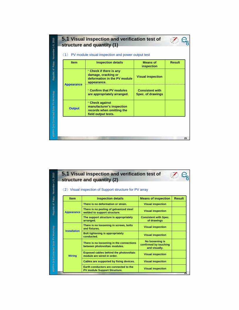
e8 /
PP
A D
SM
Wo
rksh
op
F
iji Is
lan
ds
No
vem
ber
2-6
, 200
9e8
/PP
A G
rid
Con
nect
ed S
olar
PV
Wor
ksho
p
Rep
ublic
e8
/PP
A G
rid
Con
nect
ed S
olar
PV
Wor
ksho
p
Rep
ublic
of
Pal
auof
Pal
au--
Nov
embe
r 1
Nov
embe
r 1 --
5, 2
010
5, 2
010
25
(1) PV module visual inspection and power output test
Item Inspection details Means of inspection
Result
Appearance
・・・・Check if there is any damage, cracking or deformation in the PV module appearance.
Visual inspection
・・・・Confirm that PV modules are appropriately arranged.
Consistent with Spec. of drawings
Output
・・・・Check against manufacturer’s inspection records when omitting the field output tests.
5.15.1 Visual inspection and verification test of structure and quantity (1)
e8 /
PP
A D
SM
Wo
rksh
op
F
iji Is
lan
ds
No
vem
ber
2-6
, 200
9e8
/PP
A G
rid
Con
nect
ed S
olar
PV
Wor
ksho
p
Rep
ublic
e8
/PP
A G
rid
Con
nect
ed S
olar
PV
Wor
ksho
p
Rep
ublic
of
Pal
auof
Pal
au--
Nov
embe
r 1
Nov
embe
r 1 --
5, 2
010
5, 2
010
26
(2)Visual inspection of Support structure for PV array
Item Inspection details Means of inspection Result
Appearance
There is no deformation or strain. Visual inspection
There is no peeling of galvanized steel welded to support structure. Visual inspection
The support structure is appropriately arranged.
Consistent with Spec. of drawings
Installation
There is no loosening in screws, bolts and fixtures.
Visual inspection
Bolt tightening is appropriately conducted. Visual inspection
Wiring
There is no loosening in the connections between photovoltaic modules.
No loosening is confirmed by touching
and visually.
Exposed cables behind the photovoltaic module are wired in order.
Visual inspection
Cables are supported by fixing devices. Visual inspection
Earth conductors are connected to the PV module Support Structure.
Visual inspection
5.15.1 Visual inspection and verification test of structure and quantity (2)

e8 /
PP
A D
SM
Wo
rksh
op
F
iji Is
lan
ds
No
vem
ber
2-6
, 200
9e8
/PP
A G
rid
Con
nect
ed S
olar
PV
Wor
ksho
p
Rep
ublic
e8
/PP
A G
rid
Con
nect
ed S
olar
PV
Wor
ksho
p
Rep
ublic
of
Pal
auof
Pal
au--
Nov
embe
r 1
Nov
embe
r 1 --
5, 2
010
5, 2
010
27
(3)-1 Power Conditioner
Item Inspection details Means of inspection
Result
AppearanceThere is neither peeling of surface coating nor deformation.
Visual inspection
InstallationThere is no loosening in screws, bolts and fixtures.
Visual inspection
Wiring
P/N((((+/-)))) are correctly connected at the Power Conditioner input.
Visual inspection, Multi meter
R/S/T are correctly connected at the three-phase output.
Visual inspection, Multi meter
Low voltage cable +/- are correctly connected at its input/output.
Visual inspection, Multi meter
Earthing conductors are connected. Visual inspection
Cables are connected in order. Visual inspection
The panel internal is clean. Visual inspection
Visual inspection
5.15.1 Visual inspection and verification test of structure and quantity (3)
e8 /
PP
A D
SM
Wo
rksh
op
F
iji Is
lan
ds
No
vem
ber
2-6
, 200
9e8
/PP
A G
rid
Con
nect
ed S
olar
PV
Wor
ksho
p
Rep
ublic
e8
/PP
A G
rid
Con
nect
ed S
olar
PV
Wor
ksho
p
Rep
ublic
of
Pal
auof
Pal
au--
Nov
embe
r 1
Nov
embe
r 1 --
5, 2
010
5, 2
010
28
(3)-2 Power Conditioner
Item Inspection details Performance Result Remarks
Model/typeMatching Check to the Specification document
Acceptable
Protective relay test(at factory)
Check factory inspection records on behalf of the relay test in field.
Check to factory inspection records.
Detection of
Islanding operation
MCCB((((ELCB)))) is turned off and operation is shutdown in an instance.
Acceptable
20 seconds standby
after power restoration
The power conditioner automatically starts 20 seconds after power restoration.
20[s]after restarted
Acceptable
The time to restoration shall be consistent with Tech. Spec.
Performance test
Performance test
Regarding output inspection/test of relays, check manufacturers’ factory inspection records on behalf of conducting field inspection/test.
5.15.1 Visual inspection and verification test of structure and quantity (4)
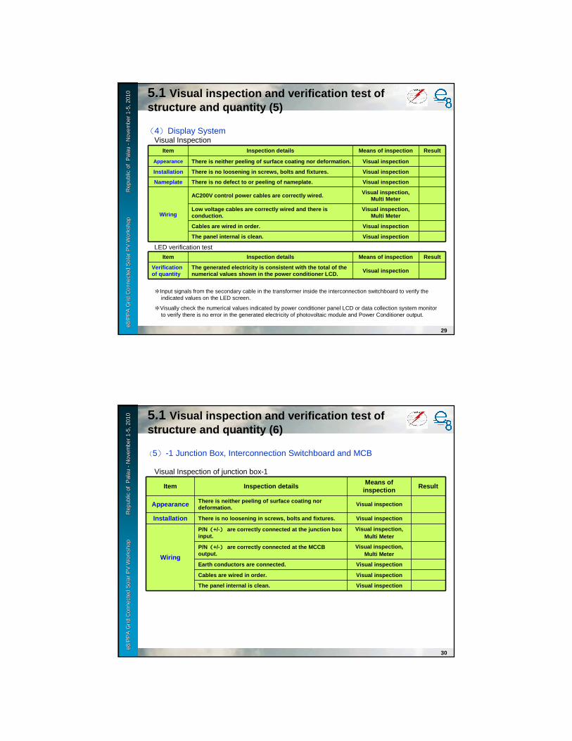
e8 /
PP
A D
SM
Wo
rksh
op
F
iji Is
lan
ds
No
vem
ber
2-6
, 200
9e8
/PP
A G
rid
Con
nect
ed S
olar
PV
Wor
ksho
p
Rep
ublic
e8
/PP
A G
rid
Con
nect
ed S
olar
PV
Wor
ksho
p
Rep
ublic
of
Pal
auof
Pal
au--
Nov
embe
r 1
Nov
embe
r 1 --
5, 2
010
5, 2
010
29
(4)Display System
Item Inspection details Means of inspection Result
Appearance There is neither peeling of surface coating nor def ormation. Visual inspection
Installation There is no loosening in screws, bolts and fixtures . Visual inspection
Nameplate There is no defect to or peeling of nameplate. Visual inspection
Wiring
AC200V control power cables are correctly wired. Visual inspection, Multi Meter
Low voltage cables are correctly wired and there is conduction.
Visual inspection, Multi Meter
Cables are wired in order. Visual inspection
The panel internal is clean. Visual inspection
Visual Inspection
LED verification test
Item Inspection details Means of inspection Result
Verification of quantity
The generated electricity is consistent with the tot al of the numerical values shown in the power conditioner LCD . Visual inspection
*Input signals from the secondary cable in the transformer inside the interconnection switchboard to verify the indicated values on the LED screen.
*Visually check the numerical values indicated by power conditioner panel LCD or data collection system monitor to verify there is no error in the generated electricity of photovoltaic module and Power Conditioner output.
5.15.1 Visual inspection and verification test of structure and quantity (5)
e8 /
PP
A D
SM
Wo
rksh
op
F
iji Is
lan
ds
No
vem
ber
2-6
, 200
9e8
/PP
A G
rid
Con
nect
ed S
olar
PV
Wor
ksho
p
Rep
ublic
e8
/PP
A G
rid
Con
nect
ed S
olar
PV
Wor
ksho
p
Rep
ublic
of
Pal
auof
Pal
au--
Nov
embe
r 1
Nov
embe
r 1 --
5, 2
010
5, 2
010
30
(5)-1 Junction Box, Interconnection Switchboard and MCB
Item Inspection detailsMeans of
inspectionResult
Appearance There is neither peeling of surface coating nor deformation.
Visual inspection
Installation There is no loosening in screws, bolts and fixtures . Visual inspection
Wiring
P/N((((+/-)))) are correctly connected at the junction box input.
Visual inspection,Multi Meter
P/N((((+/-)))) are correctly connected at the MCCB output.
Visual inspection,Multi Meter
Earth conductors are connected. Visual inspection
Cables are wired in order. Visual inspection
The panel internal is clean. Visual inspection
Visual Inspection of junction box-1
5.15.1 Visual inspection and verification test of structure and quantity (6)
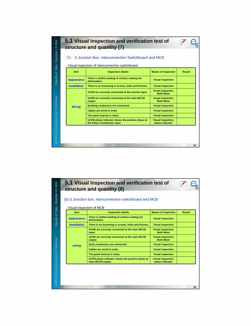
e8 /
PP
A D
SM
Wo
rksh
op
F
iji Is
lan
ds
No
vem
ber
2-6
, 200
9e8
/PP
A G
rid
Con
nect
ed S
olar
PV
Wor
ksho
p
Rep
ublic
e8
/PP
A G
rid
Con
nect
ed S
olar
PV
Wor
ksho
p
Rep
ublic
of
Pal
auof
Pal
au--
Nov
embe
r 1
Nov
embe
r 1 --
5, 2
010
5, 2
010
31
(5)-2 Junction Box, Interconnection Switchboard and MCB
Item Inspection details Means of inspection Result
Appearance There is neither peeling of surface coating nor deformation.
Visual inspection
Installation There is no loosening in screws, bolts and fixtures . Visual inspection
Wiring
U/V/W are correctly connected at the inverter input. Visual inspection, Multi Meter
U/V/W are correctly connected at the main MCCB output.
Visual inspection, Multi Meter
Earthing conductors are connected. Visual inspection
Cables are wired in order. Visual inspection
The panel internal is clean. Visual inspection
U/V/W phase indicator shows the positive phase at the Power Conditioner input
Visual inspection, phase indicator
Visual inspection of interconnection switchboard
5.15.1 Visual inspection and verification test of structure and quantity (7)
e8 /
PP
A D
SM
Wo
rksh
op
F
iji Is
lan
ds
No
vem
ber
2-6
, 200
9e8
/PP
A G
rid
Con
nect
ed S
olar
PV
Wor
ksho
p
Rep
ublic
e8
/PP
A G
rid
Con
nect
ed S
olar
PV
Wor
ksho
p
Rep
ublic
of
Pal
auof
Pal
au--
Nov
embe
r 1
Nov
embe
r 1 --
5, 2
010
5, 2
010
32
(5)-3 Junction box, interconnection switchboard and MCB
Item Inspection details Means of inspection Result
Appearance There is neither peeling of surface coating nor deformation. Visual inspection
Installation There is no loosening in screws, bolts and fixtures . Visual inspection
wiring
U/V/W are correctly connected at the main MCCB input.
Visual inspection, Multi Meter
U/V/W are correctly connected at the main MCCB output.
Visual inspection, Multi Meter
Earth conductors are connected. Visual inspection
Cables are wired in order. Visual inspection
The panel internal is clean. Visual inspection
U/V/W phase indicator shows the positive phase at main MCCB output.
Visual inspection, phase indicator
Visual inspection of MCB
5.15.1 Visual inspection and verification test of structure and quantity (8)

e8 /
PP
A D
SM
Wo
rksh
op
F
iji Is
lan
ds
No
vem
ber
2-6
, 200
9e8
/PP
A G
rid
Con
nect
ed S
olar
PV
Wor
ksho
p
Rep
ublic
e8
/PP
A G
rid
Con
nect
ed S
olar
PV
Wor
ksho
p
Rep
ublic
of
Pal
auof
Pal
au--
Nov
embe
r 1
Nov
embe
r 1 --
5, 2
010
5, 2
010
33
(1), (2) Insulation resistance measurement of cable between junction box and inverter panel
Insulation resistance measurement of cable between inverter and interconnection switchboard
Insulation resistance measurement of cables between interconnection switchboard, MCB and existing transformers
[Test procedure]Measure the insulation resistance of (+,-) polarities and (R,S,T) phases of each cable to ensure
that there is no insulation failure.
Measure the insulation resistance between each cable and the ground (according to code).
[Acceptance criteria]600V<Circuit voltage : 0.4MΩ or higher with 1000V insulation resistance tester.
300V<Circuit voltage≦600V: 0.4MΩ or higher with 500V insulation resistance tester.
150V<Circuit voltage≦300V: 0.2MΩ or higher with 500V insulation resistance tester.
Circuit voltage≦150V : 0.1MΩ or higher with 500V insulation resistance tester.
5.25.2 Equipment installation and wiring/connection inspection (1)
e8 /
PP
A D
SM
Wo
rksh
op
F
iji Is
lan
ds
No
vem
ber
2-6
, 200
9e8
/PP
A G
rid
Con
nect
ed S
olar
PV
Wor
ksho
p
Rep
ublic
e8
/PP
A G
rid
Con
nect
ed S
olar
PV
Wor
ksho
p
Rep
ublic
of
Pal
auof
Pal
au--
Nov
embe
r 1
Nov
embe
r 1 --
5, 2
010
5, 2
010
34
Measurement of cable insulation resistance
Item Insulation resistance ((((M ))))
Cable type Result
Junction box-1~~~~Power Conditioner-1
P(+) 100MΩ or higherCV10sq-4C
Ground cable 1C, spare cable 1CN(-) 100MΩ or higher
Junction box-2~Power Conditioner-2
P(+) 100MΩ or higher CV10sq-4CGround cable 1C, spare cable IC
N(-) 100MΩ or higher
Junction box-3~Power Conditioner-3
P(+) 100MΩ or higher CV10sq-4CGround cable 1C, spare cable IC
N(-) 100MΩ or higher
Power Conditioner-1 ~~~~Interconnection switchboard
R((((red)))) 100MΩ or higher
CV14sq-4CS((((black )))) 100MΩ or higher
T((((blue)))) 100MΩ or higher
N((((white )))) 100MΩ or higher
Interconnection switchboard ~~~~MCB
R((((red)))) 100MΩ or higher
CV100sq-4CS((((black )))) 100MΩ or higher
T((((blue)))) 100MΩ or higher
N((((white )))) 100MΩ or higher
MCB~~~~Existing transformer-9
R((((red)))) 100MΩ or higher
CV100sq-4CS((((black )))) 100MΩ or higher
T((((blue)))) 100MΩ or higher
N((((white )))) 100MΩ or higher
>600V
>600V
>600V
>300V
>300V
>300V
5.25.2 Equipment installation and wiring/connection inspection (2)
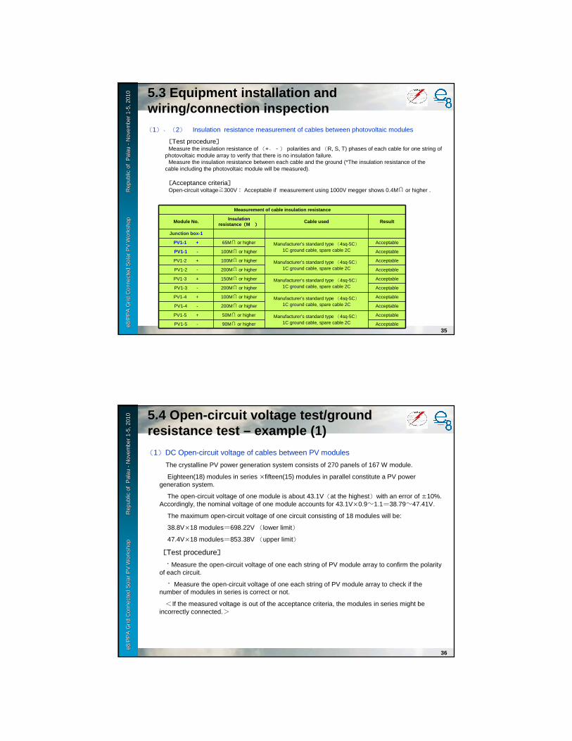
e8 /
PP
A D
SM
Wo
rksh
op
F
iji Is
lan
ds
No
vem
ber
2-6
, 200
9e8
/PP
A G
rid
Con
nect
ed S
olar
PV
Wor
ksho
p
Rep
ublic
e8
/PP
A G
rid
Con
nect
ed S
olar
PV
Wor
ksho
p
Rep
ublic
of
Pal
auof
Pal
au--
Nov
embe
r 1
Nov
embe
r 1 --
5, 2
010
5, 2
010
35
(1)、(2) Insulation resistance measurement of cables between photovoltaic modules
[Test procedure]Measure the insulation resistance of (+,-) polarities and (R, S, T) phases of each cable for one string of
photovoltaic module array to verify that there is no insulation failure.Measure the insulation resistance between each cable and the ground (*The insulation resistance of the
cable including the photovoltaic module will be measured).
[Acceptance criteria]Open-circuit voltage≧300V: Acceptable if measurement using 1000V megger shows 0.4MΩ or higher .
Measurement of cable insulation resistance
Module No. Insulation resistance ((((M )))) Cable used Result
Junction box-1
PV1-1 + 65MΩ or higher Manufacturer’s standard type (4sq-5C)1C ground cable, spare cable 2C
Acceptable
PV1-1 - 100MΩ or higher Acceptable
PV1-2 + 100MΩ or higher Manufacturer’s standard type (4sq-5C)1C ground cable, spare cable 2C
Acceptable
PV1-2 - 200MΩ or higher Acceptable
PV1-3 + 150MΩ or higher Manufacturer’s standard type (4sq-5C)1C ground cable, spare cable 2C
Acceptable
PV1-3 - 200MΩ or higher Acceptable
PV1-4 + 100MΩ or higher Manufacturer’s standard type (4sq-5C)1C ground cable, spare cable 2C
Acceptable
PV1-4 - 200MΩ or higher Acceptable
PV1-5 + 50MΩ or higher Manufacturer’s standard type (4sq-5C)1C ground cable, spare cable 2C
Acceptable
PV1-5 - 90MΩ or higher Acceptable
5.35.3 Equipment installation and wiring/connection inspection
e8 /
PP
A D
SM
Wo
rksh
op
F
iji Is
lan
ds
No
vem
ber
2-6
, 200
9e8
/PP
A G
rid
Con
nect
ed S
olar
PV
Wor
ksho
p
Rep
ublic
e8
/PP
A G
rid
Con
nect
ed S
olar
PV
Wor
ksho
p
Rep
ublic
of
Pal
auof
Pal
au--
Nov
embe
r 1
Nov
embe
r 1 --
5, 2
010
5, 2
010
36
(1)DC Open-circuit voltage of cables between PV modules
The crystalline PV power generation system consists of 270 panels of 167 W module.
Eighteen(18) modules in series ×fifteen(15) modules in parallel constitute a PV power generation system.
The open-circuit voltage of one module is about 43.1V(at the highest)with an error of ±10%.Accordingly, the nominal voltage of one module accounts for 43.1V×0.9~1.1=38.79~47.41V.
The maximum open-circuit voltage of one circuit consisting of 18 modules will be:
38.8V×18 modules=698.22V (lower limit)47.4V×18 modules=853.38V (upper limit)
[Test procedure]・Measure the open-circuit voltage of one each string of PV module array to confirm the polarity
of each circuit.
・ Measure the open-circuit voltage of one each string of PV module array to check if the number of modules in series is correct or not.
<If the measured voltage is out of the acceptance criteria, the modules in series might be incorrectly connected.>
5.45.4 Open-circuit voltage test/ground resistance test – example (1)

e8 /
PP
A D
SM
Wo
rksh
op
F
iji Is
lan
ds
No
vem
ber
2-6
, 200
9e8
/PP
A G
rid
Con
nect
ed S
olar
PV
Wor
ksho
p
Rep
ublic
e8
/PP
A G
rid
Con
nect
ed S
olar
PV
Wor
ksho
p
Rep
ublic
of
Pal
auof
Pal
au--
Nov
embe
r 1
Nov
embe
r 1 --
5, 2
010
5, 2
010
37
(2)DC Open-circuit voltage of cables between photovoltaic modules
[Test conditions]Tests shall be conducted during daytime hours on a sunny day.
(Solar radiation shall be 0.1kW/m2 or higher.)
[Acceptance criteria]Measure the open-circuit voltage of one each string of module array to confirm that it meets the
following criteria.
Measurement at junction box
Module train No.Junction box-1
Polarity ((((+,,,,-)))) Open-circuit voltage (Voc)Acceptance criteria
698V~~~~853V
Junction box-1
PV1-1 O.K 744.0V Acceptable
PV1-2 O.K 740.0V Acceptable
PV1-3 O.K 737.0V Acceptable
PV1-4 O.K 735.0V Acceptable
PV1-5 O.K 734.0V Acceptable
5.45.4 Open-circuit voltage test/ground resistance test – example (2)
e8 /
PP
A D
SM
Wo
rksh
op
F
iji Is
lan
ds
No
vem
ber
2-6
, 200
9e8
/PP
A G
rid
Con
nect
ed S
olar
PV
Wor
ksho
p
Rep
ublic
e8
/PP
A G
rid
Con
nect
ed S
olar
PV
Wor
ksho
p
Rep
ublic
of
Pal
auof
Pal
au--
Nov
embe
r 1
Nov
embe
r 1 --
5, 2
010
5, 2
010
38
(3) Earth resistance measurement
[Test procedure]Measure the earth resistance.
[Acceptance criteria]Earth resistance of 100 or less is acceptable.
Ground resistance
Item Measured value Result
Interconnection point 1.6ΩΩΩΩAcceptable
5.45.4 Open-circuit voltage test/ground resistance test – example (3)

e8 /
PP
A D
SM
Wo
rksh
op
F
iji Is
lan
ds
No
vem
ber
2-6
, 200
9e8
/PP
A G
rid
Con
nect
ed S
olar
PV
Wor
ksho
p
Rep
ublic
e8
/PP
A G
rid
Con
nect
ed S
olar
PV
Wor
ksho
p
Rep
ublic
of
Pal
auof
Pal
au--
Nov
embe
r 1
Nov
embe
r 1 --
5, 2
010
5, 2
010
39
6.6.11 Some tips for system designSome tips for system design (1)(1)
• Surrounding environment and anticipated damage
Sea breeze
Sand breeze
ContaminationElectrically grounding
Sand scratch(like frosted grass)
Falling leaf
Stone throwing
Animal bait
Falling nuts
e8 /
PP
A D
SM
Wo
rksh
op
F
iji Is
lan
ds
No
vem
ber
2-6
, 200
9e8
/PP
A G
rid
Con
nect
ed S
olar
PV
Wor
ksho
p
Rep
ublic
e8
/PP
A G
rid
Con
nect
ed S
olar
PV
Wor
ksho
p
Rep
ublic
of
Pal
auof
Pal
au--
Nov
embe
r 1
Nov
embe
r 1 --
5, 2
010
5, 2
010
40
6.6.11 Some tips for system design (2)Some tips for system design (2)
• Surrounding environment and anticipated damage
Trench for heavy rain
Strong enough for stormy wind
Lightning rod
Enough ventilationfor cooling
RainLightning
Heat upHeat up

e8 /
PP
A D
SM
Wo
rksh
op
F
iji Is
lan
ds
No
vem
ber
2-6
, 200
9e8
/PP
A G
rid
Con
nect
ed S
olar
PV
Wor
ksho
p
Rep
ublic
e8
/PP
A G
rid
Con
nect
ed S
olar
PV
Wor
ksho
p
Rep
ublic
of
Pal
auof
Pal
au--
Nov
embe
r 1
Nov
embe
r 1 --
5, 2
010
5, 2
010
4141
Monthly InspectionMonthly Inspection
Item Content of Check
PV module・・・・Surface dirt & damage・・・・Damage of wire/cable・・・・Wire’s connection and damage
Support Structure for PV module
・・・・Damage, rust & erosion・・・・Damage of wire/cable・・・・Earthing Conductor’s connection and damage
Junction Box Junction Panel
・・・・Damage, erosion & rust・・・・Damage of wire/cable・・・・Earthing Conductor’s connection and damage
6.6.22 Maintenance Plan for Photovoltaic Maintenance Plan for Photovoltaic Power Generation SystemPower Generation System (1)(1)
e8 /
PP
A D
SM
Wo
rksh
op
F
iji Is
lan
ds
No
vem
ber
2-6
, 200
9e8
/PP
A G
rid
Con
nect
ed S
olar
PV
Wor
ksho
p
Rep
ublic
e8
/PP
A G
rid
Con
nect
ed S
olar
PV
Wor
ksho
p
Rep
ublic
of
Pal
auof
Pal
au--
Nov
embe
r 1
Nov
embe
r 1 --
5, 2
010
5, 2
010
4242
Item Content of Check
Power Conditioner unit
・・・・Damage, corrosion & rust・・・・Damage of external wire/cable・・・・Earthing Conductor’s connection and damage・・・・Equipment’s allophone and nasty smell・・・・ Ambient temperature and humidity・・・・LCD indication
Instrument System
・・・・Damage, corrosion & rust・・・・Damage of external wire/cable・・・・Earthing Conductor’s connection and damage・・・・Equipment’s allophone and nasty smell・・・・Ambient temperature and humidity
Display system
・・・・Check of Power ConditionersThe numerical value that LCD of each Power Conditioner shows being about the same.
・・・・Check of Monitoring SystemThe power generation change according to Irradiance.
Monthly InspectionMonthly Inspection
6.6.22 Maintenance Plan for Photovoltaic Maintenance Plan for Photovoltaic Power Generation SystemPower Generation System (2)(2)

e8 /
PP
A D
SM
Wo
rksh
op
F
iji Is
lan
ds
No
vem
ber
2-6
, 200
9e8
/PP
A G
rid
Con
nect
ed S
olar
PV
Wor
ksho
p
Rep
ublic
e8
/PP
A G
rid
Con
nect
ed S
olar
PV
Wor
ksho
p
Rep
ublic
of
Pal
auof
Pal
au--
Nov
embe
r 1
Nov
embe
r 1 --
5, 2
010
5, 2
010
4343
Item Content of Check Measuring Check
PV module・・・・Surface dirt & damage・・・・Damage of wire/cable・・・・Wire’s connection and damage
Support Structure for PV module
・・・・Damage, corrosion & rust・・・・Damage of wire/cable・・・・Grounding wire’s connection and damage
Junction Box Junction Panel
・・・・Damage, corrosion & rust・・・・Damage of wire/cable・・・・Grounding wire’s connection and damage
・・・・Insulation resistanceEach circuit to PV in JBEach circuit to JB in JP
・・・・VOC (Volt of Circuit)Each circuit to PV in JBEach circuit to JB in JP
Regular InspectionRegular Inspection
6.6.22 Maintenance Plan for Photovoltaic Maintenance Plan for Photovoltaic Power Generation SystemPower Generation System (3)(3)
e8 /
PP
A D
SM
Wo
rksh
op
F
iji Is
lan
ds
No
vem
ber
2-6
, 200
9e8
/PP
A G
rid
Con
nect
ed S
olar
PV
Wor
ksho
p
Rep
ublic
e8
/PP
A G
rid
Con
nect
ed S
olar
PV
Wor
ksho
p
Rep
ublic
of
Pal
auof
Pal
au--
Nov
embe
r 1
Nov
embe
r 1 --
5, 2
010
5, 2
010
4444
Item Content of Check Measuring Check
Power Conditioner unit
・・・・Damage, corrosion & rust・・・・Damage of external wire/cable・・・・Grounding wire’s connection and damage・・・・Equipment’s allophone and nasty smell・・・・ Ambient temperature and humidity・・・・LCD indication
・・・・Insulation resistanceEach circuit to JP in Inv.
・・・・VOCEach circuit to JP in Inv.
Instrument System
・・・・Damage, corrosion & rust・・・・Damage of external wire/cable・・・・Grounding wire’s connection and damage・・・・Equipment’s allophone and nasty smell・・・・ Ambient temperature and humidity
Display System
・・・・Check of PCSThe numerical value that LCD of each PCS shows being about the same.
・・・・Check of Monitoring SystemThe power generation change according to Irradiance.
Regular InspectionRegular Inspection
6.6.22 Maintenance Plan for Photovoltaic Maintenance Plan for Photovoltaic Power Generation SystemPower Generation System (4)(4)
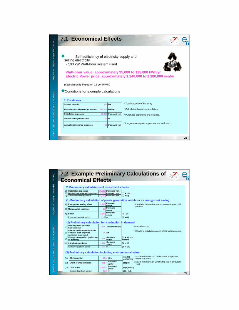
e8 /
PP
A D
SM
Wo
rksh
op
F
iji Is
lan
ds
No
vem
ber
2-6
, 200
9e8
/PP
A G
rid
Con
nect
ed S
olar
PV
Wor
ksho
p
Rep
ublic
e8
/PP
A G
rid
Con
nect
ed S
olar
PV
Wor
ksho
p
Rep
ublic
of
Pal
auof
Pal
au--
Nov
embe
r 1
Nov
embe
r 1 --
5, 2
010
5, 2
010
4545
◆ Self-sufficiency of electricity supply and selling electricity- 100 kW Watt-hour system used
Watt-hour value: approximately 95,000 to 115,000 kW h/yrElectric Power price: approximately 1,140,000 to 1, 380,000 yen/yr
(Calculation is based on 12 yen/kWh.)
◆Conditions for example calculations
1. ConditionsSystem capacity 100 kW
Annual expected power generation 115,000 kWh/yr
Installation expenses 70,000 thousand yen
General management ratio 10 %
Annual maintenance expenses 90 thousand yen
* Total capacity of PV array
* Calculated based on simulation.
* Purchase expenses are included.
* Large-scale repairs expenses are excluded.
7.1 7.1 Economical EffectsEconomical Effects
e8 /
PP
A D
SM
Wo
rksh
op
F
iji Is
lan
ds
No
vem
ber
2-6
, 200
9e8
/PP
A G
rid
Con
nect
ed S
olar
PV
Wor
ksho
p
Rep
ublic
e8
/PP
A G
rid
Con
nect
ed S
olar
PV
Wor
ksho
p
Rep
ublic
of
Pal
auof
Pal
au--
Nov
embe
r 1
Nov
embe
r 1 --
5, 2
010
5, 2
010
4646
2. Preliminary calculations of investment effects(1) Installation expenses 70,000 thousand yen(2) General management expenses 7,000 thousand yen (1) ×××× 10%(3) Total investment amount 77,000 thousand yen (1) + (2)
(1) Preliminary calculation of power generation wat t-hour as energy cost saving(4) Energy cost saving effect 1,380 thousand
yen/yr
(5) Maintenance expenses 90 thousand yen/yr
(6) Effect 1,290 thousand yen/yr
(4) - (5)
Expected payback period 59.7 yr (3) ÷÷÷÷ (6)
* Calculation is based on electric power unit price of 12 yen/kWh.
(3) Preliminary calculation including environmental value
(11) CO2 reduction 63.8 tC/yr 115000 ××××0.000555
(12) Effect of CO2 reduction 191.4 thousand yen/yr
(11) ××××3
(13) Total effect 1,887.4 thousand yen/yr
(6)+(9)+(12)
Expected payback period 40.8 Yr (3) ÷÷÷÷ (13)
(2) Preliminary calculation for a reduction in dema nd(7)
Monthly basic price for business use
1,690 Yen/ kW/month
(8) Electric power capacity under contract of an expected reduction in demand
20 kW
(9) Energy saving effect (reduction in demand)
406 thousand yen/yr
(7) ×××× (8) ××××12 months
(10) Introduction effects 1,696 thousand yen/yr
(6) + (9)
Expected payback period 45.4 yr (3) ÷÷÷÷ (10)
Expected amount
* 20% of the installation capacity of 100 kW is expected.
Calculation is based on CO2 reduction unit price of 0.000555 tC/kWh.
Calculation is based on CO2 trading rate of 3 thousand yen/t.
7.2 7.2 Example Preliminary Calculations of Example Preliminary Calculations of Economical EffectsEconomical Effects


Grid Connected Solar PV WorkshopPalau
November 1-5,2010
PV Hybrid systemPV Hybrid system(Various type of power source)(Various type of power source)
e8 /
PP
A D
SM
Wo
rksh
op
F
iji Is
lan
ds
No
vem
ber
2-6
, 200
9e8
/PP
A G
rid
Con
nect
ed S
olar
PV
Wor
ksho
p
R
epub
le8
/PP
A G
rid
Con
nect
ed S
olar
PV
Wor
ksho
p
R
epub
l ic o
f Pal
au
ic o
f Pal
au --
Nov
embe
r 1
Nov
embe
r 1 --
5, 2
010
5, 2
010
2
Off Grid: PV hybrid systems within miniOff Grid: PV hybrid systems within mini--gridgrid: : Other power source: GensetOther power source: Genset
Principle Feature Disadvantage
Diesel generator
Continuous combustion -> Combustion gas -> Reciprocating motion -> Rotational motion by crankshaft
• High heat efficiency (35-45%)• Low cost• Rapid start-up• Automatic start/stop
• Vibration• Noise• Emission (NOx)
Gas engine • Cleaner emission than DG• Smaller than DG• Available dual fuel system
• Vibration• Noise
Gas turbine Continuous combustion -> Heat energy of combustion gas -> Rotational motion by turbine
• Compact and light weight• No cooling water• Good for rapid load change• Good starting performance• Possible no load operation• Small vibration
• Slow start-up than DG
• Large fuel consumption
• Large air intake and emission

e8 /
PP
A D
SM
Wo
rksh
op
F
iji Is
lan
ds
No
vem
ber
2-6
, 200
9e8
/PP
A G
rid
Con
nect
ed S
olar
PV
Wor
ksho
p
R
epub
le8
/PP
A G
rid
Con
nect
ed S
olar
PV
Wor
ksho
p
R
epub
l ic o
f Pal
au
ic o
f Pal
au --
Nov
embe
r 1
Nov
embe
r 1 --
5, 2
010
5, 2
010
3
Off Grid: PV hybrid systems within miniOff Grid: PV hybrid systems within mini--gridgrid: : Other power source: GensetOther power source: Genset
• Fuel consumption vs output of diesel generator– High fuel consumption ratio under 50% output
Output (%)
100
76
56
39
100 110 75 50 25
112
80
100
120
140
160
Fuel consumption (%)
Fuel consumption ratio (%)
e8 /
PP
A D
SM
Wo
rksh
op
F
iji Is
lan
ds
No
vem
ber
2-6
, 200
9e8
/PP
A G
rid
Con
nect
ed S
olar
PV
Wor
ksho
p
R
epub
le8
/PP
A G
rid
Con
nect
ed S
olar
PV
Wor
ksho
p
R
epub
l ic o
f Pal
au
ic o
f Pal
au --
Nov
embe
r 1
Nov
embe
r 1 --
5, 2
010
5, 2
010
4
Off Grid: PV hybrid systems within miniOff Grid: PV hybrid systems within mini--gridgrid: : Other power source: MicroOther power source: Micro--hydrohydro
Features• Environmental friendliness• Clean energy contributing global
warming• Short construction time and easy
maintenance• Regional vitalization• Reduction of running cost at existing
water facility• More reliable energy source than PV
or Wind Source: NEDO
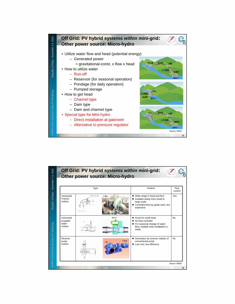
e8 /
PP
A D
SM
Wo
rksh
op
F
iji Is
lan
ds
No
vem
ber
2-6
, 200
9e8
/PP
A G
rid
Con
nect
ed S
olar
PV
Wor
ksho
p
R
epub
le8
/PP
A G
rid
Con
nect
ed S
olar
PV
Wor
ksho
p
R
epub
l ic o
f Pal
au
ic o
f Pal
au --
Nov
embe
r 1
Nov
embe
r 1 --
5, 2
010
5, 2
010
5
Off Grid: PV hybrid systems within miniOff Grid: PV hybrid systems within mini--gridgrid: : Other power source: MicroOther power source: Micro--hydrohydro
• Utilize water flow and head (potential energy)– Generated power
= gravitational-const. x flow x head• How to utilize water
– Run-off– Reservoir (for seasonal operation)– Pondage (for daily operation)– Pumped storage
• How to get head– Channel type– Dam type– Dam and channel type
• Special type for Mini-hydro– Direct installation at gate/weir– Alternative to pressure regulator
Source: NEDO
e8 /
PP
A D
SM
Wo
rksh
op
F
iji Is
lan
ds
No
vem
ber
2-6
, 200
9e8
/PP
A G
rid
Con
nect
ed S
olar
PV
Wor
ksho
p
R
epub
le8
/PP
A G
rid
Con
nect
ed S
olar
PV
Wor
ksho
p
R
epub
l ic o
f Pal
au
ic o
f Pal
au --
Nov
embe
r 1
Nov
embe
r 1 --
5, 2
010
5, 2
010
6
Off Grid: PV hybrid systems within miniOff Grid: PV hybrid systems within mini--gridgrid: : Other power source: MicroOther power source: Micro--hydrohydro
Type Feature Flow control
Horizontal Francis turbine
� Wide range in head and flow� Installed widely from small to
large scale� Controlled flow by guide-vane, but
expensive
Yes
Horizontalpropeller water turbine
� Good for small head� No flow controller� For seasonal change of water
flow, multiple units installation is made.
No
Reverse pump turbine
� Generation by reverse rotation of conventional pump
� Low cost, low efficiency
No
Source: NEDO
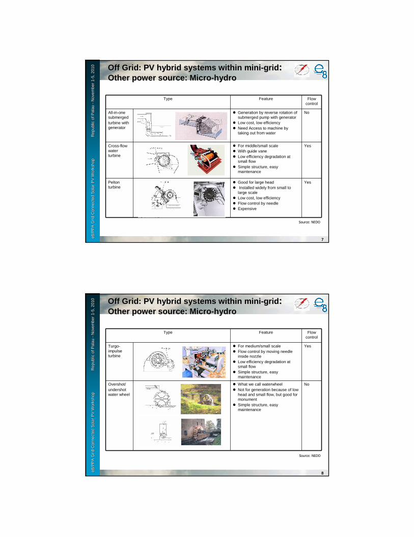
e8 /
PP
A D
SM
Wo
rksh
op
F
iji Is
lan
ds
No
vem
ber
2-6
, 200
9e8
/PP
A G
rid
Con
nect
ed S
olar
PV
Wor
ksho
p
R
epub
le8
/PP
A G
rid
Con
nect
ed S
olar
PV
Wor
ksho
p
R
epub
l ic o
f Pal
au
ic o
f Pal
au --
Nov
embe
r 1
Nov
embe
r 1 --
5, 2
010
5, 2
010
7
Off Grid: PV hybrid systems within miniOff Grid: PV hybrid systems within mini--gridgrid: : Other power source: MicroOther power source: Micro--hydrohydro
Type Feature Flow control
All-in-one submergedturbine with generator
� Generation by reverse rotation of submerged pump with generator
� Low cost, low efficiency� Need Access to machine by
taking out from water
No
Cross-flow water turbine
� For middle/small scale� With guide vane� Low efficiency degradation at
small flow� Simple structure, easy
maintenance
Yes
Peltonturbine
� Good for large head� Installed widely from small to
large scale� Low cost, low efficiency� Flow control by needle� Expensive
Yes
Source: NEDO
e8 /
PP
A D
SM
Wo
rksh
op
F
iji Is
lan
ds
No
vem
ber
2-6
, 200
9e8
/PP
A G
rid
Con
nect
ed S
olar
PV
Wor
ksho
p
R
epub
le8
/PP
A G
rid
Con
nect
ed S
olar
PV
Wor
ksho
p
R
epub
l ic o
f Pal
au
ic o
f Pal
au --
Nov
embe
r 1
Nov
embe
r 1 --
5, 2
010
5, 2
010
8
Off Grid: PV hybrid systems within miniOff Grid: PV hybrid systems within mini--gridgrid: : Other power source: MicroOther power source: Micro--hydrohydro
Type Feature Flow control
Turgo-impulse turbine
� For medium/small scale� Flow control by moving needle
inside nozzle� Low efficiency degradation at
small flow� Simple structure, easy
maintenance
Yes
Overshot/undershot water wheel
� What we call waterwheel� Not for generation because of low
head and small flow, but good for monument
� Simple structure, easy maintenance
No
Source: NEDO

e8 /
PP
A D
SM
Wo
rksh
op
F
iji Is
lan
ds
No
vem
ber
2-6
, 200
9e8
/PP
A G
rid
Con
nect
ed S
olar
PV
Wor
ksho
p
R
epub
le8
/PP
A G
rid
Con
nect
ed S
olar
PV
Wor
ksho
p
R
epub
l ic o
f Pal
au
ic o
f Pal
au --
Nov
embe
r 1
Nov
embe
r 1 --
5, 2
010
5, 2
010
9
Off Grid: PV hybrid systems within miniOff Grid: PV hybrid systems within mini--gridgrid: : Other power source: MicroOther power source: Micro--hydrohydro
• Possible application
Target flow
Target site Characteristics
Flow Head/Pressure Others
RiverChannel
Mountain streamMountain runoffSand prevention dam
� Torrent� Large fluctuation� Possible heavy
flood
� Easily obtainable head by steep slope
� Suffering driftwood� Risk of banking
sand, landslide or water disaster
� Maintenance of river system
Hilly area, highland,Slope section of flat land or water intake facility
� Fluctuation� Possible of
flood/drought� Flow-down of
garbage � Possible water
pollution
� Hard to obtain large head except for heavy slope
� Near to demand area
� Limitation of usage by flood/drought
� Necessity of dust removal
� Maintenance of river system
� Environmental friendliness
e8 /
PP
A D
SM
Wo
rksh
op
F
iji Is
lan
ds
No
vem
ber
2-6
, 200
9e8
/PP
A G
rid
Con
nect
ed S
olar
PV
Wor
ksho
p
R
epub
le8
/PP
A G
rid
Con
nect
ed S
olar
PV
Wor
ksho
p
R
epub
l ic o
f Pal
au
ic o
f Pal
au --
Nov
embe
r 1
Nov
embe
r 1 --
5, 2
010
5, 2
010
10
Off Grid: PV hybrid systems within miniOff Grid: PV hybrid systems within mini--gridgrid: : Other power source: MicroOther power source: Micro--hydrohydro
• Possible application
Target flow Target site Characteristics
Flow Head/Pressure Others
Agricultural water
Main lineChannelWater pipe line
� Large difference in flow between irrigation season and non-irrigation season
� Hard to obtain large head by low-gradient
� Depends on height of end-point
Sub line � Difference in flow between irrigation season and non-irrigation season
� Fluctuation of intake by agricultural field
� Flow-down of garbage
� Necessity of dust removal
� Maintenance of river system
� Environmental friendliness
Control point of flow, pressure and inclination
� Easily obtainable head, but maybe small head
� Modification or improvement of existing facility

e8 /
PP
A D
SM
Wo
rksh
op
F
iji Is
lan
ds
No
vem
ber
2-6
, 200
9e8
/PP
A G
rid
Con
nect
ed S
olar
PV
Wor
ksho
p
R
epub
le8
/PP
A G
rid
Con
nect
ed S
olar
PV
Wor
ksho
p
R
epub
l ic o
f Pal
au
ic o
f Pal
au --
Nov
embe
r 1
Nov
embe
r 1 --
5, 2
010
5, 2
010
11
Off Grid: PV hybrid systems within miniOff Grid: PV hybrid systems within mini--gridgrid: : Other power source: MicroOther power source: Micro--hydrohydro
• Possible application
Target flow Target site Characteristics
Flow Head/Pressure Others
Industrial and daily life water
Water transmission line
� Relatively constant flow
� Easily obtainable head by remote demand area from source
� Possible water pipe
Industrial effluent and sewage
Discharge channel
� Easily obtainable of constant flow
� Depends on tail water level
� Water quality� Emergency
stop by facility trouble
In-house supply and drain water system
Supply and drain water channel
� Stable� Various flow
quantity depends on production process
� Utilization of regulated and surplus water pressure
� Easily obtainable head or pressure
� Necessity of consideration about harmlessness against primary water use
e8 /
PP
A D
SM
Wo
rksh
op
F
iji Is
lan
ds
No
vem
ber
2-6
, 200
9e8
/PP
A G
rid
Con
nect
ed S
olar
PV
Wor
ksho
p
R
epub
le8
/PP
A G
rid
Con
nect
ed S
olar
PV
Wor
ksho
p
R
epub
l ic o
f Pal
au
ic o
f Pal
au --
Nov
embe
r 1
Nov
embe
r 1 --
5, 2
010
5, 2
010
12
Off Grid: PV hybrid systems within miniOff Grid: PV hybrid systems within mini--gridgrid: : Other power source: MicroOther power source: Micro--hydrohydro
• Example of direct installation
Gate
Generator
Example of installation at sand prevention dam
Water intake
Sand prevention dam
Water channel
Generatorhouse
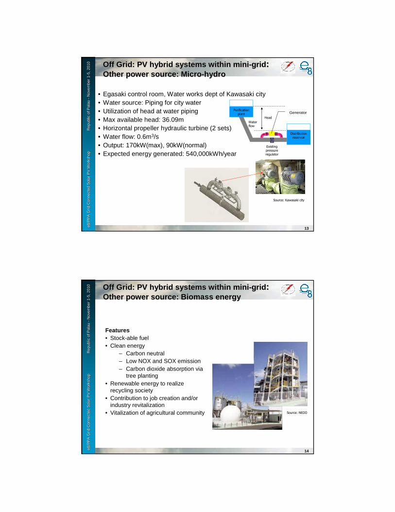
e8 /
PP
A D
SM
Wo
rksh
op
F
iji Is
lan
ds
No
vem
ber
2-6
, 200
9e8
/PP
A G
rid
Con
nect
ed S
olar
PV
Wor
ksho
p
R
epub
le8
/PP
A G
rid
Con
nect
ed S
olar
PV
Wor
ksho
p
R
epub
l ic o
f Pal
au
ic o
f Pal
au --
Nov
embe
r 1
Nov
embe
r 1 --
5, 2
010
5, 2
010
13
Off Grid: PV hybrid systems within miniOff Grid: PV hybrid systems within mini--gridgrid: : Other power source: MicroOther power source: Micro--hydrohydro
• Egasaki control room, Water works dept of Kawasaki city• Water source: Piping for city water• Utilization of head at water piping• Max available head: 36.09m• Horizontal propeller hydraulic turbine (2 sets)• Water flow: 0.6m3/s• Output: 170kW(max), 90kW(normal)• Expected energy generated: 540,000kWh/year
Distribution reservoir
Head
Purification plant
Water flow
Existing pressure regulator
Generator
Source: Kawasaki city
e8 /
PP
A D
SM
Wo
rksh
op
F
iji Is
lan
ds
No
vem
ber
2-6
, 200
9e8
/PP
A G
rid
Con
nect
ed S
olar
PV
Wor
ksho
p
R
epub
le8
/PP
A G
rid
Con
nect
ed S
olar
PV
Wor
ksho
p
R
epub
l ic o
f Pal
au
ic o
f Pal
au --
Nov
embe
r 1
Nov
embe
r 1 --
5, 2
010
5, 2
010
14
Off Grid: PV hybrid systems within miniOff Grid: PV hybrid systems within mini--gridgrid: : Other power source: Biomass energyOther power source: Biomass energy
Features• Stock-able fuel• Clean energy
– Carbon neutral– Low NOX and SOX emission– Carbon dioxide absorption via
tree planting• Renewable energy to realize
recycling society • Contribution to job creation and/or
industry revitalization• Vitalization of agricultural community Source: NEDO

e8 /
PP
A D
SM
Wo
rksh
op
F
iji Is
lan
ds
No
vem
ber
2-6
, 200
9e8
/PP
A G
rid
Con
nect
ed S
olar
PV
Wor
ksho
p
R
epub
le8
/PP
A G
rid
Con
nect
ed S
olar
PV
Wor
ksho
p
R
epub
l ic o
f Pal
au
ic o
f Pal
au --
Nov
embe
r 1
Nov
embe
r 1 --
5, 2
010
5, 2
010
15
Off Grid: PV hybrid systems within miniOff Grid: PV hybrid systems within mini--gridgrid: : Other power source: Biomass energyOther power source: Biomass energy
Biomass resources
Unutilized resource
Woody material Remaining materials at forest land, thinned wood, unused tree
Remaining material of lumbering, scrap wood from construction, others
Paper Used paper, sludge from paper production, black liquor
Agricultural residue
Rice straw, rice husk, straw, bagasse, others
Night soil, dung and sludge
Cow dung, pig dung, chicken dung, others
Sewage sludge, sludge from night soil purification
Leftover food Waste from food processing
wholesale market and food retailing
Kitchen waste from home and restaurant
Waste cooking oil
Others Landfill gas, waste fiber
Productive resource
Woody material Short cycle cultivated lumber
Herbal material Grass, waterweed, see grass
Others Sugar, starch, palm oil, rape oil
e8 /
PP
A D
SM
Wo
rksh
op
F
iji Is
lan
ds
No
vem
ber
2-6
, 200
9e8
/PP
A G
rid
Con
nect
ed S
olar
PV
Wor
ksho
p
R
epub
le8
/PP
A G
rid
Con
nect
ed S
olar
PV
Wor
ksho
p
R
epub
l ic o
f Pal
au
ic o
f Pal
au --
Nov
embe
r 1
Nov
embe
r 1 --
5, 2
010
5, 2
010
16
Off Grid: PV hybrid systems within miniOff Grid: PV hybrid systems within mini--gridgrid: : Other power source: Biomass energyOther power source: Biomass energy
Biomass processing
Thermo chemical conversion
Direct combustion
gasification Molten gasification
Partial oxidation gasification
Cold fluidized bed gasification
Supercritical water gasification
Liquidization Fast pylolysis
Slurry fuel
Carbonization
Esterification
Biochemical conversion
Methane fermentation Wet process
Dry process
Two-stage fermentation
Ethanol fermentation

e8 /
PP
A D
SM
Wo
rksh
op
F
iji Is
lan
ds
No
vem
ber
2-6
, 200
9e8
/PP
A G
rid
Con
nect
ed S
olar
PV
Wor
ksho
p
R
epub
le8
/PP
A G
rid
Con
nect
ed S
olar
PV
Wor
ksho
p
R
epub
l ic o
f Pal
au
ic o
f Pal
au --
Nov
embe
r 1
Nov
embe
r 1 --
5, 2
010
5, 2
010
17
Off Grid: PV hybrid systems within miniOff Grid: PV hybrid systems within mini--gridgrid: : Other power source: Biomass energyOther power source: Biomass energy
Silo
Scrap woodLumber mill
Turbine/generator
Boiler
Power to other load
Power to factory load
Direct combustion system for woody material
Source: NEDO
e8 /
PP
A D
SM
Wo
rksh
op
F
iji Is
lan
ds
No
vem
ber
2-6
, 200
9e8
/PP
A G
rid
Con
nect
ed S
olar
PV
Wor
ksho
p
R
epub
le8
/PP
A G
rid
Con
nect
ed S
olar
PV
Wor
ksho
p
R
epub
l ic o
f Pal
au
ic o
f Pal
au --
Nov
embe
r 1
Nov
embe
r 1 --
5, 2
010
5, 2
010
18
Off Grid: PV hybrid systems within miniOff Grid: PV hybrid systems within mini--gridgrid: : Other power source: Biomass energyOther power source: Biomass energy
Gasification generation system for woody material
Belt conveyer
Hawking unit
Slide gate
Gasification unit
Electric cylinder
Gasifyer
Electric cylinderRostle
oscillating unit
Engine generator
Electric valve
Electric valve Heat recovery unit
Waste gas combustion unit
BypassAutomatic igniterPropane gas bottle
Auxiliary panelOn/Off signal
Controlpanel
Source: NEDO

e8 /
PP
A D
SM
Wo
rksh
op
F
iji Is
lan
ds
No
vem
ber
2-6
, 200
9e8
/PP
A G
rid
Con
nect
ed S
olar
PV
Wor
ksho
p
R
epub
le8
/PP
A G
rid
Con
nect
ed S
olar
PV
Wor
ksho
p
R
epub
l ic o
f Pal
au
ic o
f Pal
au --
Nov
embe
r 1
Nov
embe
r 1 --
5, 2
010
5, 2
010
19
Off Grid: PV hybrid systems within miniOff Grid: PV hybrid systems within mini--gridgrid: : Other power source: Biomass energyOther power source: Biomass energy
Typical example of furnace
Rotary kiln Stoker furnaceSource: NEDO
e8 /
PP
A D
SM
Wo
rksh
op
F
iji Is
lan
ds
No
vem
ber
2-6
, 200
9e8
/PP
A G
rid
Con
nect
ed S
olar
PV
Wor
ksho
p
R
epub
le8
/PP
A G
rid
Con
nect
ed S
olar
PV
Wor
ksho
p
R
epub
l ic o
f Pal
au
ic o
f Pal
au --
Nov
embe
r 1
Nov
embe
r 1 --
5, 2
010
5, 2
010
20
Off Grid: PV hybrid systems within miniOff Grid: PV hybrid systems within mini--gridgrid: : Other power source: Biomass energyOther power source: Biomass energy
Yagi bio ecology center
Yagi bio ecology center
GeneratorFermenter, gas holderSource: NEDO

e8 /
PP
A D
SM
Wo
rksh
op
F
iji Is
lan
ds
No
vem
ber
2-6
, 200
9e8
/PP
A G
rid
Con
nect
ed S
olar
PV
Wor
ksho
p
R
epub
le8
/PP
A G
rid
Con
nect
ed S
olar
PV
Wor
ksho
p
R
epub
l ic o
f Pal
au
ic o
f Pal
au --
Nov
embe
r 1
Nov
embe
r 1 --
5, 2
010
5, 2
010
21
Off Grid: PV hybrid systems within miniOff Grid: PV hybrid systems within mini--gridgrid: : Other power source: Biomass energyOther power source: Biomass energy
Yagi bio ecology center
Source: NEDO
Cow dung, pig dung, straw,
sawdust
Receiving tank
Bean curd refuse
Raw water tank
Gas holder
Fremen-
ter
Waste water treatment
Reuse
Effluent to river
Compost
Dehydrated cake
Liquid fertilizer
Desulferization
Digestion tank
Hot water boiler
(backup)
Surplus gas combustion
Power
Digestion tank
Digestive juice
Hydro extractor
Waste water treatment (Existing)
Digestive gas
Hot water
Digestion bath
Fremen-
ter
Digestive gas
Gas holder
Generator
e8 /
PP
A D
SM
Wo
rksh
op
F
iji Is
lan
ds
No
vem
ber
2-6
, 200
9e8
/PP
A G
rid
Con
nect
ed S
olar
PV
Wor
ksho
p
R
epub
le8
/PP
A G
rid
Con
nect
ed S
olar
PV
Wor
ksho
p
R
epub
l ic o
f Pal
au
ic o
f Pal
au --
Nov
embe
r 1
Nov
embe
r 1 --
5, 2
010
5, 2
010
22
Off Grid: PV hybrid systems within miniOff Grid: PV hybrid systems within mini--gridgrid: : Other power source: Wind powerOther power source: Wind power
FeaturesClean energy
– No carbon dioxide emissionDomestic energy resourceRenewable energyMost economical among new energy
resourcesStable generation cost Awareness for energy and global
warming issueContribution to local region
Source: NEDO

e8 /
PP
A D
SM
Wo
rksh
op
F
iji Is
lan
ds
No
vem
ber
2-6
, 200
9e8
/PP
A G
rid
Con
nect
ed S
olar
PV
Wor
ksho
p
R
epub
le8
/PP
A G
rid
Con
nect
ed S
olar
PV
Wor
ksho
p
R
epub
l ic o
f Pal
au
ic o
f Pal
au --
Nov
embe
r 1
Nov
embe
r 1 --
5, 2
010
5, 2
010
23
Off Grid: PV hybrid systems within miniOff Grid: PV hybrid systems within mini--gridgrid: : Other power source: Wind powerOther power source: Wind power
Windmill
Multi-bladed
Darrieus
Sabonius type
Puddle
Cross-flow
S-shaped rotor
Drag type
Straight wing
Vertical axis
Horizontal axis Lift type
Lift type
Propeller
Sail wing
Holland type
Up wind
Down wind
Multi-bladed
Darrieus
Sabonius type Puddle
Cross-flow S-shaped rotor
Straight wing
Vertical axis
Horizontal axis
Propeller Sail wing
Holland type
Source: NEDO
e8 /
PP
A D
SM
Wo
rksh
op
F
iji Is
lan
ds
No
vem
ber
2-6
, 200
9e8
/PP
A G
rid
Con
nect
ed S
olar
PV
Wor
ksho
p
R
epub
le8
/PP
A G
rid
Con
nect
ed S
olar
PV
Wor
ksho
p
R
epub
l ic o
f Pal
au
ic o
f Pal
au --
Nov
embe
r 1
Nov
embe
r 1 --
5, 2
010
5, 2
010
24
Off Grid: PV hybrid systems within miniOff Grid: PV hybrid systems within mini--gridgrid: : Other power source: Wind powerOther power source: Wind power
Type Feature
Horizontal axis � Simple structure� High efficiency� Easy to scale-up� Good for generation� Need yaw control for up-wind type� Heavy load exists in nacelle.
Vertical axis
� Not depend on wind direction� Heavy load exists on ground.� Easy manufacturing of blade compared to propeller� Hard to control rotation speed� Need large torque in start-up� Lower efficiency rather than horizontal axis type� Large footprint
Lift type
� Good for generation by higher peripheral velocity than wind speed
� Less blades has higher peripheral velocity
Drag type
� Many application in small scale� Large torque� Peripheral velocity is less than wind speed� Good for pump-up and grinding flour� Lower efficiency than lift type
Source: NEDO

e8 /
PP
A D
SM
Wo
rksh
op
F
iji Is
lan
ds
No
vem
ber
2-6
, 200
9e8
/PP
A G
rid
Con
nect
ed S
olar
PV
Wor
ksho
p
R
epub
le8
/PP
A G
rid
Con
nect
ed S
olar
PV
Wor
ksho
p
R
epub
l ic o
f Pal
au
ic o
f Pal
au --
Nov
embe
r 1
Nov
embe
r 1 --
5, 2
010
5, 2
010
25
Off Grid: PV hybrid systems within miniOff Grid: PV hybrid systems within mini--gridgrid: : Other power source: Wind powerOther power source: Wind power
Blade
Speed-up gear
Generator
Drive train axis
Anemovane
Nacelle
Communication line
Console
Monitoring system
Transformer
Hub
Rotor axis
Tower
Power conversion system
Controller
Foundation
Report
Brake system
Yaw drive unit
Power pole
Protection system
Distribution line
Displayboard
Source: NEDO
e8 /
PP
A D
SM
Wo
rksh
op
F
iji Is
lan
ds
No
vem
ber
2-6
, 200
9e8
/PP
A G
rid
Con
nect
ed S
olar
PV
Wor
ksho
p
R
epub
le8
/PP
A G
rid
Con
nect
ed S
olar
PV
Wor
ksho
p
R
epub
l ic o
f Pal
au
ic o
f Pal
au --
Nov
embe
r 1
Nov
embe
r 1 --
5, 2
010
5, 2
010
26
Off Grid: PV hybrid systems within miniOff Grid: PV hybrid systems within mini--gridgrid: : Other power source: Wind powerOther power source: Wind power
Rotor (fixed speed)
Rotor (variable speed)
Induction generator
Induction generator
Synchronousgenerator
Speed-up gear
3 phase AC(power freq.)
Rotor (variable speed)
Speed-up gear
3 phase AC(power freq.)
3 phase AC(power freq.)
(a) AC link (Induction generator)
(b) DC link (Induction generator)
(c) DC link (Synchronous generator)
DC
Converter Inverter
InverterConverter
3 phase AC(control freq.)
3 phase AC(control freq.)
3 phase AC(power freq.)
Source: NEDO