106 a,b,c,d,e - physics-math.com · s., jr.: summary ofairfoil data. naca rep. 824 (1945)....
TRANSCRIPT

USOO8827211B2
(12) United States Patent (10) Patent No.: US 8,827,211 B2 Kremeyer (45) Date of Patent: Sep. 9, 2014
(54) LASER-BASED FLOW MODIFICATION TO 6,782,790 132* 8/2004 Barrett ......................... .. 89/111
REMOTELY CONTROL AIR VEHICLE FLIGHT PATH
(76) Inventor: Kevin Kremeyer, Tucson, AZ (US)
( * ) Notice: Subject to any disclaimer, the term of this patent is extended or adjusted under 35 U.S.C. 154(b) by 585 days.
(21) Appl.No.: 12/289,262
(22) Filed: Oct. 23, 2008
(65) Prior Publication Data
US 2009/0173836 A1 Jul. 9, 2009
Related US. Application Data
(60) Provisional application No. 60/960,976, ?led on Oct. 23, 2007.
(51) Int. Cl. B64C 19/00 (2006.01) B64C 23/00 (2006.01)
(52) U.S.Cl. USPC ......................... .. 244/204; 244/201; 244/751
(58) Field of Classi?cation Search USPC ..... .. 244/205, 204, 204.1, 1 N, 1 R, 130, 198,
244/201, 203, 75.1 See application ?le for complete search history.
(56) References Cited
U.S. PATENT DOCUMENTS
3,719,829 A 3/1973 Vaill 5,263,661 A * 11/1993 Riley .......................... .. 244/1N 5,797,563 A * 8/1998 Blackburn et a1. .. 244/130 6,247,671 B1 * 6/2001 Sacks et al. ................. .. 244/205
6,370,219 B1 4/2002 Peale 6,401,589 B1* 6/2002 Pinkus et al. .................. .. 89/11 6,527,221 B1 * 3/2003 Kremeyer ................... .. 244/1 N
6,793,177 B2* 9/2004 Bonutti .. 244/78.1 6,824,108 B2* 11/2004 Bonutti ..... .. 244/201
7,063,288 B1* 6/2006 Kremeyer 244/1 R 7,121,511 B2* 10/2006 Kremeyer .... .. 244/130 7,641,153 B2* 1/2010 Smereczniak . 244/205 7,648,100 B2* 1/2010 Kremeyer .... .. 244/1 R 7,930,967 B2* 4/2011 Marquis et al. .. 89/3617
2004/0084568 A1* 5/2004 Bonutti ........ .. 244/204
2004/0084569 A1* 5/2004 Bonutti 244/204 2004/0118270 A1* 6/2004 Barrett ...... .. 89/1.11
2005/0061908 A1* 3/2005 Kremeyer 244/1N 2005/0150371 A1* 7/2005 Rickard .... .. 89/1.11
2007/0040726 A1* 2/2007 Kremeyer 342/52 2007/0176046 A1* 8/2007 Kremeyer .... .. 244/1 N 2009/0084252 A1* 4/2009 Marquis et al. 89/1.11 2009/0173837 A1* 7/2009 Silkeyet al. 244/205 2011/0030379 A1* 2/2011 Kremeyer ..................... .. 60/768
FOREIGN PATENT DOCUMENTS
W0 WO 2006134050 A1 * 12/2006
OTHER PUBLICATIONS
Abbott, Ira H., Von Doenhoff, Albert E., and Stivers, Louis S., Jr., “Summary ofAirfoil Data,” NACA Rep., 824 (1945). Lachowicz, J. M., Yao, C. S., and WleZien, Richard W., “Flow ?eld characterization of a jet and vortex actuator,” Experiments in Fluids, v01. 27, Issue 1 (1999) 12-20.
(Continued)
Primary Examiner * Joseph W Sanderson
(74) Attorney, Agent, or Firm * Jones Day
(57) ABSTRACT
Systems, equipment, and methods to deposit energy to modify and control air ?oW, lift, and drag, in relation to air vehicles, and methods for seeding ?ow instabilities at the leading edges of control surfaces, primarily through shock Wave generation through deposition of laser energy at a dis tance.
12 Claims, 3 Drawing Sheets
106 a,b,c,d,e

US 8,827,211 B2 Page 2
(56) References Cited
OTHER PUBLICATIONS Schewe, G., “Reynolds-number effects in ?ow around more-or-less bluff bodies,” Journal of Wind Engineering and Industrial Aerody namics, 89 (2001) 1267-1289. Smetana, Frederick O., Summey, Delbert C., Smith, Neill S., and Carden, Ronald K., “Light Aircraft Lift, Drag, and Moment Predic tioniA Review and Analysis,” NASA CR-2523 (1975).
WleZien, Richard W. and Ferraro, P. J ., “Aeroacoustic Environment of an Advanced STOVL Aircraft in Hover,” AIAA J., 30:11 (1992) 2606-2612. WleZien, Richard W., Parekh, D. E., and Island, T., “Measurement of Acoustic Receptivity at Leading Edges and Porous Strips,” Applied Mechanics Reviews, 43:5 Part 2 (1990) $167-$174.
* cited by examiner

US. Patent Sep. 9, 2014 Sheet 1 0f3 US 8,827,211 B2
Fig. 1
/104
Fig. 2

US. Patent Sep. 9, 2014 Sheet 2 0f3 US 8,827,211 B2

US. Patent
‘9 .8
L6
L4
1.2
1.0 CI.
0.8
0.8
0,4
0.2 >
0.0
Sep. 9, 2014 Sheet 3 0f3 US 8,827,211 B2
5 1-06 2 a 10° 2 5 197 2
be! a c
g 12.5 a 0‘ a 33 °3 A 50 '90
Q1: 6
Q 5:51: b
o g a a II ‘7 UFT
' If e I 6
a 105 2 a M)5 2 :- 10’ 2
Reynolds - Number
Fig. 4

US 8,827,211 B2 1
LASER-BASED FLOW MODIFICATION TO REMOTELY CONTROL AIR VEHICLE
FLIGHT PATH
CROSS REFERENCE TO RELATED APPLICATION
This application claims the bene?t of priority from US. Provisional Patent Application No. 60/960,976, ?led Oct. 23, 2007. The US. provisional application, in its entirety, is incorporated herein by reference.
The following patents and patent applications are each incorporated herein by reference in their entirety:
1) US. Pat. No. 6,527,221, which granted on Mar. 4, 2003, entitled “Shockwave Modi?cation, Method and Appa ratus and System,”
2) US. Pat. No. 7,063,288, which granted on Jun. 20, 2006, entitled “Shockwave Modi?cation, Method and Sys tem,”
3) US. Pat. No. 7, 121,51 1, which granted on Oct. 17, 2006, entitled “Shockwave Modi?cation, Method and Sys tem,”
4) US. patent application Ser. No. 11/288,425 ?led on Nov. 29, 2005 and entitled “Shockwave Modi?cation, Method and System,”
5) US. patent application Ser. No. 11/540,964 ?led on Oct. 2, 2006 and entitled “Shockwave Modi?cation, Method and System,” and
6) International Patent Application No. PCT/US2008/ 009885 ?led on Aug. 20, 2008 and entitled “Energy Deposition Systems, Equipment and Methods for Modi fying and Controlling Shock Waves and Supersonic Flow.”
FIELD OF THE INVENTION
This invention relates to systems, equipment, and methods to deposit energy to remotely modify and control ?uid ?ow along control surfaces of an air vehicle, in order to control its ?ight path and descent. The invention more speci?cally relates to lasers, acoustic excitation, and ablative shock waves, as well as non-lethal vehicle stopping.
BACKGROUND OF THE INVENTION
Air vehicle control is achieved through modifying ?ow across control surfaces, typically by adjusting ?aps and angle of attack. Flow along the control surfaces can be modi?ed in other ways to allow external control of the air vehicle. This can be achieved by generating excitations to seed instabilities that lead to transitions in the ?ow along the control surface, (such as boundary layer separation leading to decreased lift, stall, etc). Several publications discuss this (see below for a few), and one general term used to describe the phenomenon is “receptivity” of the speci?c driving frequency being picked up and ampli?ed as it propagates along the control surface.
Abbott, Ira H. , Von Doenhoff, Albert E., and Stivers, Louis S., Jr.: Summary ofAirfoil Data. NACA Rep. 824 (1945).
LachowicZ, J. M., Yao, C. S., and WleZien, Richard W.: Flow ?eld characterization of a jet and vortex actuator, Experiments in Fluids, Volume 27, Issue 1, pp. 12-20 (1999).
Schewe, G., Reynolds-number effects in ?ow around more-or-less bluff bodies, Journal of Wind Engineering and Industrial Aerodynamics 89, 1267-1289 (2001).
Smetana, Frederick O., Summey, Delbert C., Smith, Neill S., and Carden, Ronald K.: Light Aircraft Lift, Drag, and Moment PredictioniA Review and Analysis. NASA CR-2523 (1975).
20
25
30
35
40
45
50
55
60
65
2 WleZien, Richard W. and Ferraro, P. 1.: Aeroacoustic Envi
ronment of an Advanced STOVL Aircraft in Hover, AIAA J. Vol. 30 (11), pp. 2606-2612 (1992).
WleZien, Richard W., Parekh, D. E., and Island, T.: Mea surement of Acoustic Receptivity at Leading Edges and Porous Strips, Applied Mechanics Reviews, Vol. 43, 5, Part 2, pp. S167-S174 (1990). The basic concept is that certain frequency excitations
grow exponentially when seeded at the leading edge of a control surface, other frequencies die down and lead to stable ?ow. Seeding these frequencies, even very lightly, can lead to dramatic modi?cation to the ?ow across the control surface, in particular, in loss of laminar ?ow, replaced by separated ?ow, leading to a strong reduction in lift, in fact leading to stall under the right conditions (or a dramatic loss in lift). The excitations we will provide are mediated/delivered via laser and much of the pertinent background is described in great detail in the Kremeyer patents included by reference. The laser-induced shockwaves we introduce, either on or near a
surface, seed an extremely broad frequency range, encom passing the unstable (growing) frequencies, as well as stable (non-growing) frequencies. Even a very weak one-time intro duction of an unstable frequency is expected to grow, as a result, introduction of the broad spectrum by the shockwaves at the leading edge is expected to seed all of the growing modes to disrupt ?ow. Performing this repeatedly/repetitively will ensure signi?cant and lasting ?ow disruption on the targeted control surface.
BRIEF SUMMARY OF THE INVENTION
In one aspect, the present invention relates to systems, equipment, and methods to deposit energy to modify and control ?ow along the control surfaces of a remote air vehicle.
In another aspect, the systems, equipment, and methods can be used to control the ?ight path of an uncooperative air vehicle.
In another aspect, the systems, equipment, and methods can be used to ground an uncooperative air vehicle.
In another aspect, the systems, equipment, and methods can be based on and deployed from a chase plane.
In another aspect, the systems, equipment, and methods can be based on and deployed from a waterborne craft.
In another aspect, the systems, equipment, and methods can be based on and deployed from a land vehicle.
In another aspect, the systems, equipment, and methods can be based on and deployed from a ?xed station.
In another aspect, the systems, equipment, and methods can be comprised of multiple laser systems, based on any combination of air vehicles, waterborne craft, land vehicles, and ?xed stations, targeting any number of remote air vehicles.
In some embodiments, the energy deposition can take place in the form of repeated shockwaves generated by laser ablation on the leading edge of control and/or lifting surfaces such as wings, stabilizers, and rotors.
In some embodiments, the energy deposition can be deliv ered through repetition of a focused laser beam.
In some embodiments, the energy deposition can be deliv ered through repetition of a ?lamenting laser.
In some embodiments, the ?lamenting laser can deposit the energy directly onto the leading edge of the control surfaces via ablation.
In some embodiments, the ?lamenting laser can deposit the energy along the leading edge by forming the laser ?lament parallel to the control surface leading edge.

US 8,827,211 B2 3
Several embodiments of the invention, including the above aspects of the invention, are described in further detail as follows, and in the inventions incorporated. Generally, each of these embodiments can be used in various and speci?c combinations, and with other aspects and embodiments unless otherwise stated herein.
BRIEF DESCRIPTION OF THE DRAWINGS
FIG. 1 shows a schematic of a pursuit plane employing the laser-based ?ow-modi?cation technology to increase drag and reduce lift on one side of the ?eeing air vehicle.
FIG. 2 shows a schematic of a machine-vision view of a target vehicle, allowing the leading edges to be identi?ed and tracked during the ensuing target/chase-plane maneuvers.
FIG. 3 shows a shadowgraph image of the expanding shockwave from a nanosecond laser energy deposited in atmosphere on an aluminum surface.
FIG. 4 shows a graph of Lift vs. Reynolds Number for the Growian-Pro?le at 12 deg AOA. A strong drop in lift results with transitions to/ from laminar ?ow (Schewe).
DETAILED DESCRIPTION OF THE INVENTION
The following detailed description, and the accompanying drawings to which it refers, are provided describing and illus trating certain examples or speci?c embodiments of the invention only and not for the purpose of exhaustively describing all possible embodiments and examples of the invention. Thus, this detailed description does not in any way limit the scope of the inventions claimed in this patent appli cation or in any patent(s) issuing from this or any related application.
To facilitate the understanding of the subject matter dis closed herein, a number of terms, abbreviations or other shorthand as used herein are de?ned below. These de?nitions are intended to complement the usage common to those skilled in the art. Any term, abbreviation or shorthand not de?ned is understood to have the ordinary meaning used by a skilled artisan contemporaneous with the submission of this application.
The term “air vehicle” is used herein to mean any manned or unmanned air vehicle or platform, such as any airplane, launch or re-entry vehicle, space-plane, missile, cruise mis sile, or the like. A laser-based approach is proposed modify this ?ow from
a remote platform, such as a chase plane (FIG. 1). This approach will allow preferential modi?cation of control forces to allow external control. This external control will allow steering forces and modi?ed lift to be imposed, in order to steer and/ or gradually and safely bring the targeted aircraft down. More dramatic control can be exerted if called for by initiating stall on the wings. This form of external control on the vehicle is safer and more compelling than the current options of electrically/mechanically disabling the vehicle or engaging in risky maneuvers that can endanger both the target and chase planes/occupants.Any damage to the target vehicle surface will be minimal. There is a market for this capability in government sectors, allowing smugglers and threats to be apprehended and/ or deterred without risking loss of life. The proposed technology consists of rastering a pulsed laser at range along the leading edge of a control surface to preferen tially increase or decrease the “lift” it generates. The drag on the control surface can also be preferentially increased. The ?nal system will employ machine vision (FIG. 2) to track the control surface leading edges, ensuring sustained application of the extemally-applied control throughout the course of the
20
25
30
35
40
45
50
55
60
65
4 chase- and target-vehicle dynamic s/ maneuvers. The rotors of rotary aircraft can similarly be disrupted, in fact in certain embodiments, quite simply, by pulse-illuminating the entire rotor (in the case of a small stabiliZing rotor), or a portion of a larger rotor, for example the large lifting rotor. This illumi nation can modify the ?ow along the rotary lifting and control surfaces in order to control both lift and rotary stabilization.
Vision: Current vehicle stopping technologies, including electromagnetic-and mechanical-incapacitation of a vehicle would prove very di?icult to employ as a non-lethal weapon against airplanes in an interdiction scenario. In contrast, the proposed concept is applicable for use in interdiction mis sions and is envisioned to be employable and effective in chase-type scenarios where the targeted aircraft is ?eeing from the chase plane. The cost of each use will come only from the electricity required to run the system (with the asso ciated crew, fuel, and plane maintenance). The technology is further anticipated to operate at useful ranges, in excess of 500 m. The proposed technology development effort stands to yield a system to remotely control a ?eeing vehicle by adjust ing the lift and drag experienced by key control surfaces (control surfaces include both ?xed and moving surfaces, generating lift, drag, and any other forces to enable ?ight and/or control). This will allow aircraft to be redirected, gen tly brought to a landing, or more quickly removed from the sky by suddenly initiating stall on the wings. Rotorcraft have similar considerations, dealing mainly with the upward and stabiliZing tail force. The application of external force will be disruptive and confusing to the ?eeing pilot, and control can be returned to the ?eeing vehicle by simply disengaging the technology. In any number of chase scenarios, depending on the ?eeing pilot’s cooperativeness, full control can be returned to the pilot, moderate external control can be main tained, or the aircraft can be stalled if neces sary. The approach does not necessarily have to be employed from above and/or behind the targeted vehicle. It can also be employed from below, from the side, or from in front of the ?eeing vehicle, or from any position allowing a line-of-sight to the control/ lifting surfaces to be affected. The technology also does not need to be housed on a manned chase-aircraft. It can be housed on an unmanned aircraft, a lighter-than-air platform, or a craft in space, or any other craft capable of housing it. The technology can further be housed on stationary structures or surface craft, such as land vehicles or waterborne craft, such as unmanned surface craft, unmanned underwater craft, boats, ships, or submarines. Similarly, a man-portable system can be envisioned.
Technical Rationale: The modi?cation of aerodynamic ?ows through controlled disturbances has been studied in various forms for many years. The localized addition of ther mal or acoustic energy can have a large effect on developing ?ow?elds (e.g. as they propagate along the control surface after ?owing across the leading edge). Even if only very small perturbations are seeded at the leading edge, if performed periodically, within the relatively broad band of unstable driving frequencies, these very small seed oscillations will grow as the ?ow propagates along the control surface to generate large-scale oscillations that determine the transition to turbulence and detached ?ow. This can strongly affect the performance of the control surface (FIG. 4). These studies have been pioneered by Tollmien, Schlichting, and Goertler. Our application calls for use of a pulsed laser to locally generate heating and expansion of the air at the surface of the air foil’s leading edge, thereby providing a ?ow control per turbation capable of gross modi?cation of airplane aerody namics. Known ?ow modi?cation schemes, which can be employed, include:
US 8,827,211 B2 5
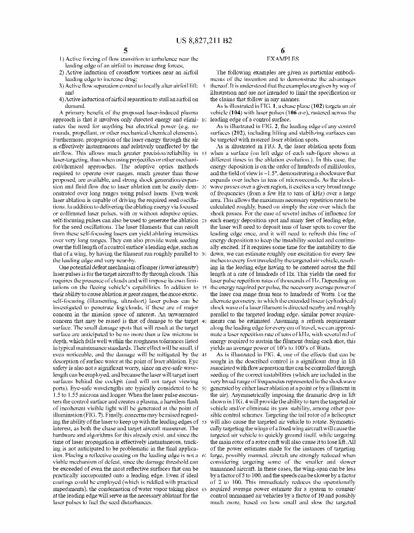
1) Active forcing of ?ow transition to turbulence near the leading edge of an airfoil to increase drag forces;
2) Active induction of cross?ow vortices near an airfoil leading edge to increase drag;
3) Active ?ow separation control to locally alter airfoil lift; and
4) Active induction of airfoil separation to stall an airfoil on demand.
A primary bene?t of the proposed laser-induced plasma approach is that it involves only directed energy and elimi nates the need for anything but electrical power (e.g. no rounds, propellant, or other mechanical/chemical elements). Furthermore, propagation of the laser energy through the air is effectively instantaneous and relatively unaffected by the air/?ow. This allows much greater precision/reliability in laser-targeting, than when using projectiles or other mechani cal/chemical approaches. The adaptive optics methods required to operate over ranges, much greater than those proposed, are available, and strong shock generation/expan sion and ?uid ?ow due to laser ablation can be easily dem onstrated over long ranges using pulsed lasers. Even weak laser ablation is capable of driving the required seed oscilla tions. In addition to delivering the ablating energy via focused or collimated laser pulses, with or without adaptive optics, self-focusing pulses can also be used to generate the ablation for the seed oscillations. The laser ?laments that can result from these self-focusing lasers can yield ablating intensities over very long ranges. They can also provide weak seeding over the full length of a control surface’ s leading edge, such as that of a wing, by having the ?lament run roughly parallel to the leading edge and very near-by. One potential defeat mechanism of longer (lower intensity)
laser pulses is for the target aircraft to ?y through clouds. This requires the presence of clouds and will impose its own limi tations on the ?eeing vehicle’s capabilities. In addition to their ability to cause ablation at great ranges, the more exotic, self-focusing (?lamenting, ultrashort) laser pulses can be investigated to penetrate fog/clouds, if these are of major concern in the mission space of interest. An unwarranted concern that may be raised is that of damage to the target surface. The small damage spots that will result at the target surface are anticipated to be no more than a few microns in depth, which falls well within the roughness tolerances listed in typical maintenance standards. Their effect will be small, if even noticeable, and the damage will be mitigated by the desorption of surface water at the point of laser ablation. Eye safety is also not a signi?cant worry, since an eye-safe wave length can be employed, and because the laser will target inert surfaces behind the cockpit (and will not target viewing ports). Eye-safe wavelengths are typically considered to be 1.5 to 1.55 microns and longer. When the laser pulse encoun ters the control surface and creates a plasma, a harmless ?ash of incoherent visible light will be generated at the point of illumination (FIG. 7). Finally, concerns may be raised regard ing the ability of the laser to keep up with the leading edges of interest, as both the chase and target aircraft maneuver. The hardware and algorithms for this already exist, and since the time of laser propagation is effectively instantaneous, track ing is not anticipated to be problematic in the ?nal applica tion. Placing a re?ective coating on the leading edge is not a viable mechanism of defeat, since the damage threshold can be exceeded of even the most re?ective surfaces that can be practically incorporated onto a leading edge. Even if ideal coatings could be employed (which is riddled with practical impediments), the condensation of water vapor taking place at the leading edge will serve as the necessary ablatant for the laser pulses to fuel the seed disturbances.
20
25
30
35
40
45
50
55
60
65
6 EXAMPLES
The following examples are given as particular embodi ments of the invention and to demonstrate the advantages thereof. It is understood that the examples are given by way of illustration and are not intended to limit the speci?cation or the claims that follow in any manner. As is illustrated in FIG. 1, a chase plane (102) targets an air
vehicle (104) with laser pulses (106 a-e), rastered across the leading edge of a control surface. As is illustrated in FIG. 2, the leading edge of any control
surfaces (202), including lifting and stabiliZing surfaces can be targeted with rastered laser ablation spots. As is illustrated in FIG. 3, the laser ablation spots form
when a surface (on left edge of each sub-?gure shown at different times in the ablation evolution.). In this case, the energy deposition is on the order of hundreds of milliJoules, and the ?eld of view is ~1 .5", demonstrating a shockwave that expands over inches in tens of microseconds. As the shock wave passes over a given region, it excites a very broad range of frequencies (from a few HZ to tens of kHZ) over a large area. This allows the maximum necessary repetition rate to be calculated roughly, based on simply the size over which the shock passes. For the case of several inches of in?uence for each energy deposition spot and many feet of leading edge, the laser will need to deposit tens of laser spots to cover the leading edge once, and it will need to refresh this line of energy deposition to keep the instability seeded and continu ally excited. If it requires some time for the instability to die down, we can estimate roughly one excitation for every few inches to every foot traveled by the targeted air vehicle, result ing in the leading edge having to be rastered across the full length at a rate of hundreds of HZ. This yields the need for laser pulse repetition rates of thousands of HZ. Depending on the energy required per pulse, the necessary average power of the laser can range from tens to hundreds of Watts. For the alternate geometry, in which the extended linear (cylindrical) shock wave of a laser ?lament is directed nearby and roughly parallel to the targeted leading edge, similar power require ments can be estimated. Assuming a refresh requirement along the leading edge for every cm of travel, we can approxi mate a laser repetition rate of tens of kHZ, with several m] of energy required to sustain the ?lament during each shot, this yields an average power of 10’s to 100’s of Watts. As is illustrated in FIG. 4, one of the effects that can be
sought in the described control is a signi?cant drop in lift associated with ?ow separation that can be controlled through seeding of the correct instabilities (which are included in the very broad range of frequencies represented in the shockwave generated by either laser ablation at a point or by a ?lament in the air). Asymmetrically imposing the dramatic drop in lift shown in FIG. 4 will provide the ability to turn the targeted air vehicle and/or eliminate its yaw stability, among other pos sible control schemes. Targeting the tail rotor of a helicopter will also cause the targeted air vehicle to rotate. Symmetri cally targeting the wings of a ?xed wing aircraft will cause the targeted air vehicle to quickly ground itself, while targeting the main rotor of a rotor craft will also cause it to lose lift. All of the power estimates made for the instances of targeting large, possibly manned, aircraft are strongly reduced when considering targeting some of the smaller and slower unmanned aircraft. In these cases, the wing-span can be less by a factor of 5 to 100, and the speeds canbe slower by a factor of 2 to 100. This immediately reduces the operationally required average power estimate for a system to counter/ control unmanned air vehicles by a factor of 10 and possibly much more, based on how small and slow the targeted

US 8,827,211 B2 7
unmanned vehicles are. This places the various ranges of average power requirements at 1-10 kW if wanting to ensure a fully powered system, 100-1000 W for a system suf?cient for most needs, and then laser systems of 1-1000 W average power for targeting smaller aircraft such as small unmanned air vehicles.
What is claimed is: 1. An energy deposition system, comprising: one or more 100 to 1000 watt, average power, pulsed laser
sources mounted on a chase vehicle; a sub-assembly for tracking a leading edge of at least one or more control surfaces of an uncooperative air vehicle; and
control hardware in communication with the tracking sub assembly and in control of the one or more pulsed laser
sources; wherein, in response to the tracking, the control hardware
processes a control algorithm for controlling the one or more pulsed laser sources to remotely deposit laser energy to generate laser-induced plasma on the leading edge of the at least one or more control surfaces of the uncooperative vehicle.
2. The system of claim 1, wherein the control hardware controls the one or more pulsed laser sources to deliver at least one laser-induced plasma excitation per every inch to foot of travel by the uncooperative air vehicle, resulting in the lead ing edge of the at least one or more control surfaces of the
20
25
8 uncooperative air vehicle being rastered across its full length by the one or more pulsed laser sources at a rate of more than 100 HertZ.
3. The system of claim 1, wherein the system is located on a chase plane.
4. The system of claim 1, wherein the system is located on one or more waterborne craft.
5. The system of claim 1, wherein the system is located on some combination of one or more air vehicles, land vehicles, waterborne craft, and ?xed stations.
6. The system of claim 1, wherein the control hardware controls the one or more pulsed laser sources to steer the uncooperative air vehicle.
7. The system of claim 6, wherein the system is located on a chase plane.
8. The system of claim 6, wherein the system is located on one or more waterborne craft.
9. The system of claim 1, wherein the control hardware is pro grammed to control the placement and timing of the one or more pulsed laser sources.
10. The system of claim 9, wherein the control hardware controls the one or more pulsed laser sources to steer the uncooperative air vehicle.
11. The system of claim 10, wherein the system is located on a chase plane.
12. The system of claim 10, wherein the system is located on one or more waterborne craft.
* * * * *