108-94264 prod spec hva630-2p b1 - dalroad€¦ · with an 180deg cable outlet the sealed connector...
TRANSCRIPT
Product Specification
108-94264 Rev B1
Document Class 1
©2011 Tyco Electronics Corporation, a TE Connectivity Ltd. Company All Rights Reserved | Indicates Change
1 of 22
*Trademark. TE Connectivity, TE connectivity (logo), and TE (logo) are trademarks. Other logos, product and/or Company names may be trademarks of their respective owners.
LOC B
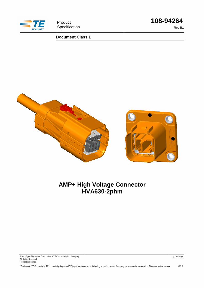
AMP+ High Voltage Connector HVA630-2phm

108-94264
Rev B1
2 of 22
TABLE OF CONTENTS INHALTSVERZEICHNIS
1. Scope / Anwendungsbereich .................................................................................................. 4
1.1. Introduction / Einführung ............................................................................................................................... 4
1.2. Content / Inhalt .............................................................................................................................................. 4
1.3. Qualification / Qualifikation ............................................................................................................................ 4
2. Applicable Documents / Anwendbare Unterlagen ................................................................. 5
2.1. TE Connectivity Documents / TE Connectivity Unterlagen ............................................................................ 5
2.2. Other Documents / Allgemeine Unterlagen ................................................................................................... 7
3. Requirements / Anforderungen .............................................................................................. 8
3.1. Design and Construction / Entwurf und Konstruktion .................................................................................... 8
3.2. Material / Werkstoffe ..................................................................................................................................... 8
3.3. Product Ratings / Produkt- und Leistungsmerkmale ..................................................................................... 8
3.4. Performance and Test Description / Leistung und Testdurchführung ........................................................... 9
3.5. Test Requirements and Procedures Summary / Testanforderungen und Testergebnisse .......................... 10
3.6. Test sequence / Prüfreihenfolge ................................................................................................................. 16
3.7. Additional Test Procedures / Zusätzliche Testdurchführungen ................................................................... 16
4. Quality Assurance Provisions / Qualitätsicherungsmaßnahmen ....................................... 17
4.1. Qualification Testing / Qualifikationsprüfung ............................................................................................... 17
4.2. Requalification Testing / Requalifikationsprüfung ........................................................................................ 17
5. Appendix / Anhang ................................................................................................................ 18
5.1. Housing influence on derating / DERATING IM GEHÄUSE ........................................................................ 18
5.2. Dynamic load / Dynamische Beanspruchung .............................................................................................. 20
5.3. Contact engagement length / Kontaktüberdeckung .................................................................................... 22
108-94264
Rev B1
3 of 22
CHANGE HISTORY ÄNDERUNGSHISTORIE
Rev. Rev.
Change Änderung
Origin ator Bearbeiter
Approved Freigegeben
Date Datum
A New document / Neues Dokument T. Reissnegger A. Metzker 14SEP2012
A1 Page 9 reference to 501 -94009 deleted, Derating updated Seite 9 Verweis zu 501-94009 gelöscht, Derating aktualisiert
R. Schwan F. Fittrock 24MAR2015
B Change to new high -volume tooling including product improvements Wechsel zu Serienwerkzeugen inkl. Produkt-verbesserungen
R. Schwan F. Fittrock 14APR2015
B1 Page 8/22 Dielectric withstand voltage corrected to 2700V Seite 8/22 Bemessungs-Stoßspannung korrigiert auf 2700V
R. Schwan K.Kioschis 23NOV2016
Only the German version is authoritative. Maßgebend ist nur der deutsche Text.

108-94264
Rev B1
4 of 22
1. SCOPE / ANWENDUNGSBEREICH
1.1. Introduction / Einführung
TE Connectivity’s touch-proof 2 position connector HVA630 and header are designed on the basis of LV215-1 specification, which has been deve loped by working group 4.3.3. It is designed for a metric wire size of 2x4mm² and 2x6mm². With an 180deg cable outlet the sealed connector sy stem implies two AMP MCP 6.3/4.8K contacts and an integrated High Voltage Interlock ( HVIL) system. The HVA630 incorporates 360deg conductive EMI shields to reduce radiated em issions in the application. The housings are molded in orange to denote a high voltage syste m.
TE Connectivity’s berührgeschützter 2pol. Steckverbinder HVA630 und Stiftleiste sind auf Basis der Designrichtlinie LV215-1, welche im Arbeitskreis Nr. 4.3.3 erarbeitet wurde, entwickelt worden. Sie sind für einen metrischen Leitungsquerschnitt von 2x4mm² und 2x6mm² ausgelegt. Das gedichtete Stecksystem beinhaltet mit einem 180° Leitungsabgang zwei AMP MCP 6.3/4.8K Leistungskontakte und ein integriertes Hochvolt-Interlock (HVIL) System. Zur Reduzierung der abgestrahlten Emissionen ist der HVA630 mit 360°-Sc hirmblechen ausgeführt. Zur Kennzeichnung der Hochvoltanwendung sind die Gehäuse in orange ausgeführt.
1.2. Content / Inhalt
This specification covers the performance, tests an d quality requirements for the 2 pos. HV-Connector with AMP MCP 6.3/4.8K Contact system. Per formance, tests and quality requirements of the contact systems are not part of this specification, but are included by the validation of the connector system. Diese Spezifikation beschreibt die Eigenschaften, Tests und Qualitätsanforderungen des 2 poligen HV-Steckverbinders mit AMP MCP 6.3/4.8K Kontaktsystem. Eigenschaften, Tests und Qualitätsanforderungen an die verwendeten Kontaktsysteme sind nicht Bestandteil dieser Spezifikation, jedoch im Umfang der Validation des Stecksystems enthalten.
1.3. Qualification / Qualifikation
When tests are performed the following specificatio ns and standards shall be used. All inspections shall be performed using the applicable inspection plan and customer drawing.
Die nachfolgenden Prüfungen sind nach den genannten Richtlinien und Normungen einzuhalten und müssen nach den zugehörigen Prüfplänen und Kundenzeichnungen durchgeführt werden.
108-94264
Rev B1
5 of 22
2. APPLICABLE DOCUMENTS / ANWENDBARE UNTERLAGEN
The following mentioned documents are part of this specification. Unless otherwise specified, the latest edition of the documents applies. In the event of conflict between the requirements of this specification and the information contained in the referenced documents, this specification shall take precedence (exempt from documents to the contact systems).
Die nachfolgenden Unterlagen, sofern darauf verwiesen wird, sind Teil dieser Spezifikation. Falls nicht anders spezifiziert sind die jeweils letztgültigen Dokumente anzuwenden. Im Falle des Widerspruches zwischen dieser Spezifikationen oder Informationen von anderen technischen Dokumentationen, hat diese Spezifikation Vorrang (ausgenommen Kontaktspezifische Dokumente).
2.1. TE Connectivity Documents / TE Connectivity Unterlagen
A General Requirements / Generelle Anforderungen
Requirements Requirements
Description Beschreibung
109-1; Rev. J General Requirements for Testi ng Generelle Anforderungen für Tests
B Customer drawings / Kundenzeichnungen
2pos HV-Connector 2pol HV-Steckverbinder
2287490 HVA630-2PHM PLUG HSG, OVERVIEW KIT HVA630-2phm Stecker, Übersicht KIT
2141256 PLUG HOUSING ASSY, CODED Steckergeh. Baugruppe, Kodiert
2141259 RECEPTACLE HSG, ASSY Kontaktgehaeuse Baugruppe
2141261 SHIEL CRIMP FERRULE, INNER Untercrimphülse
2141262 SHIELDING Schirmung
2141263 OUTER CRIMP FERRULE Äussere Crimphülse
2141264 CABLE SEAL Kabeldichtung
2141265 COVER Abdeckkappe

108-94264
Rev B1
6 of 22
2pos Pinheader 2pol Stiftwanne
2141272 HEADER ASSY, HV-Connector, 2 POS. Stiftwanne, HV-Steckverbinder, 2-polig
Interface drawings Schnittstellenzeichnungen
114-94036 Interface Drawing, 2 POS. HV Schnittstellenzeichnung 2-polig HV
114-94039 Interface Drawing TAB 6.3/4.8 FOR HV TAB -HEADER Schnittstellenzeichnung Flachstecker 6.3/4.8 für HV-Stiftwanne
114-94201 CONTACT PIN REGULATION MCON -1.2x0.6 Ausführungsvorschrift Kontaktstift MCON-1.2x0.6
114-94037 Interfa ce Drawing, Adapter Plate HV A630-2p Schnittstellenzeichnung, Aufnahmeplatte HVA630-2p
C Specifications / Spezifikationen
Specification Spezifikation
Description Beschreibung
108-18718 Product Specification AMP MCP 6.3/4.8K Contact Syst em Produktspezifikation AMP MCP 6.3/4.8K Kontakt System
108-18782 Product Specification MCON -1.2 Contact System Produktspezifikation MCON-1.2 Kontaktsystem
114-94100 Application Specification for HVA630 -2phm Verarbeitungsspezifikation für HVA630-2phm
114-18388 Applica tion Specifications for AMP MCP 6.3/4.8K Contact Sy stem Verarbeitungsspezifikation für AMP MCP 6.3/4.8K Kontaktsystem
114-18464 Application Specifications MCON -1.2 Contact Sy stem Verarbeitungsspezifikation MCON-1.2 Kontaktsystem

108-94264
Rev B1
7 of 22
2.2. Other Documents / Allgemeine Unterlagen
Document number Dokumentnummer
Edition Datum
Standard: Title, A uthor Norm: Titel, Autor
DIN EN 60664-1 2008-01 Isolation coordination for equipment within low -voltage systems - Part 1: Principles, requirements and tests
Isolationskoordinaten für elektrische Betriebsmittel in Niederspannungsanlagen Teil 1: Grundsätze, Anforderungen und Prüfungen
ISO 20653 2013-02 Road vehicles - Degrees of protection (IP -Code) - Protection of electrical equipment against foreign objects, water and access
Straßenfahrzeuge, Schutzarten (IP-Code) - Schutz gegen fremde Objekte, Wasser und Kontakt – Elektrische Ausrüstungen
ISO 6469-3 2011-12 Electrically propelled road vehicles - Safety specifications - Part 3: Protection of persons against electric shock
Elektrisch angetriebene Straßenfahrzeuge - Sicherheitsspezifikation - Teil 3: Schutz von Personen gegen elektrischen Schlag
ISO 16750 -1: 2006-08 -2: 2012-11 -3: 2012-12 -4: 2010-04
Electric road vehicles – Environmental conditions and testing for electrical and electronic equipment
Straßenfahrzeuge – Umgebungsbedingungen und Prüfungen für elektrische und elektronische Ausrüstungen
LV 214-1 2010-03 Test specification for motor vehicle connectors AK Prüfrichtlinie für Kfz-Steckverbinder
LV 215-1 2013-02 Electrical/Electronic Requirements of HV Connectors
Elektrik / Elektronik Anforderungen an HV- Kontaktierungen - Lastenheft
LV215-2 2013-02 Test specification for HV motor vehicle connectors KFZ-Hochvolt-Kontaktierung - Prüfnorm
108-94264
Rev B1
8 of 22
3. REQUIREMENTS / ANFORDERUNGEN
3.1. Design and Construction / Entwurf und Konstruktion
The product design, construction and physical dimen sions corresponds to the latest customer drawings. Please note, prototype parts or pre-serial parts ca n be differing slightly in dimensioning, form- and position tolerances to the interface drawings. Das Produkt entspricht in seiner Ausführung und seinen physikalischen Abmessungen den letztgültigen Kundenzeichnungen. Prototypen- oder Vorserienteile können in geringfügigen Bereichen von den Maßen, Form- und Lagetoleranzen der Schnittstellenzeichnungen abweichen.
3.2. Material / Werkstoffe
Descriptions for material see latest valid customer drawings.
Angaben hierzu sind den letztgültigen Kundenzeichnungen zu entnehmen.
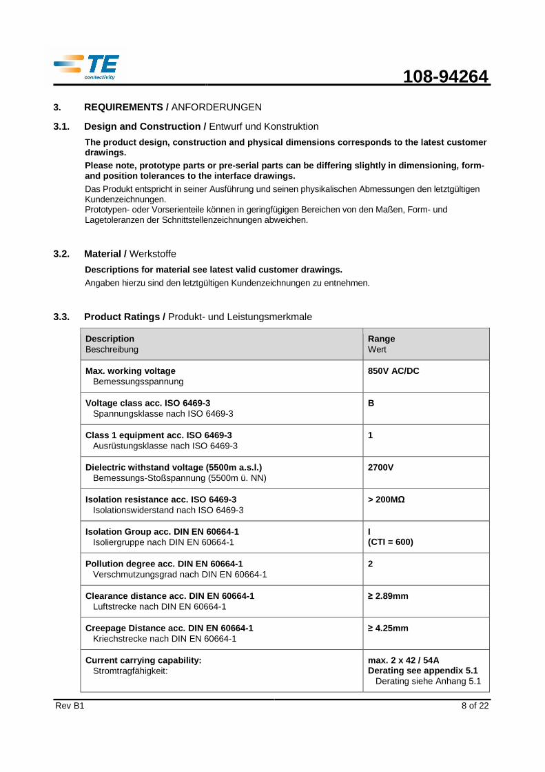
3.3. Product Ratings / Produkt- und Leistungsmerkmale
Description Beschreibung
Range Wert
Max. working voltage Bemessungsspannung
850V AC/DC
Voltage class acc. ISO 6469 -3 Spannungsklasse nach ISO 6469-3
B
Class 1 equipment acc. ISO 6469 -3 Ausrüstungsklasse nach ISO 6469-3
1
Dielectric withsta nd vol tage (5500m a.s.l.) Bemessungs-Stoßspannung (5500m ü. NN)
2700V
Isolation resist ance acc. ISO 6469 -3 Isolationswiderstand nach ISO 6469-3
> 200MΩ
Isolation Group acc. DIN EN 60664 -1 Isoliergruppe nach DIN EN 60664-1
I (CTI = 600)
Pollution degree acc. DIN EN 60664 -1 Verschmutzungsgrad nach DIN EN 60664-1
2
Clearance distance acc. DIN EN 60664-1 Luftstrecke nach DIN EN 60664-1
≥ 2.89mm
Creepag e Distance acc. DIN EN 60664 -1 Kriechstrecke nach DIN EN 60664-1
≥ 4.25mm
Current carrying capability: Stromtragfähigkeit:
max. 2 x 42 / 54A Derating see appendix 5.1
Derating siehe Anhang 5.1
108-94264
Rev B1
9 of 22
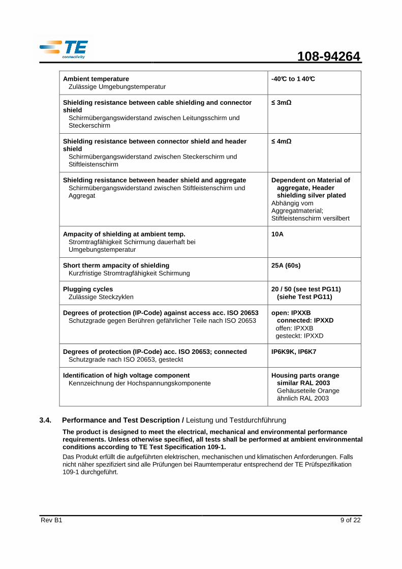
Ambient temperature Zulässige Umgebungstemperatur
-40°C to 1 40°C
Shielding resistance between cable shielding and connector shield
Schirmübergangswiderstand zwischen Leitungsschirm und Steckerschirm
≤ 3mΩ
Shielding resistance between connector shield and header shield
Schirmübergangswiderstand zwischen Steckerschirm und Stiftleistenschirm
≤ 4mΩ
Shielding resistance between header shield and aggregate Schirmübergangswiderstand zwischen Stiftleistenschirm und Aggregat
Dependent on Material of aggregate, Header shielding silver plated
Abhängig vom Aggregatmaterial; Stiftleistenschirm versilbert
Ampacity of shielding at ambient temp. Stromtragfähigkeit Schirmung dauerhaft bei Umgebungstemperatur
10A
Short therm ampacity of shielding Kurzfristige Stromtragfähigkeit Schirmung
25A (60s)
Plugging cycles Zulässige Steckzyklen
20 / 50 (see test PG11) (siehe Test PG11)
Degrees of protection (IP -Code) against access acc. ISO 20653 Schutzgrade gegen Berühren gefährlicher Teile nach ISO 20653
open : IPXXB connected: IPXXD offen: IPXXB gesteckt: IPXXD
Degrees of protection (I P-Code) acc. ISO 20653; connected Schutzgrade nach ISO 20653, gesteckt
IP6K9K, IP6K7
Identification of high voltage component Kennzeichnung der Hochspannungskomponente
Housing parts orange similar RAL 2003 Gehäuseteile Orange ähnlich RAL 2003
3.4. Performance and Test Description / Leistung und Testdurchführung
The product is designed to meet the electrical, mec hanical and environmental performance requirements. Unless otherwise specified, all tests shall be performed at ambient environmental conditions according to TE Test Specification 109-1 .
Das Produkt erfüllt die aufgeführten elektrischen, mechanischen und klimatischen Anforderungen. Falls nicht näher spezifiziert sind alle Prüfungen bei Raumtemperatur entsprechend der TE Prüfspezifikation 109-1 durchgeführt.
108-94264
Rev B1
10 of 22
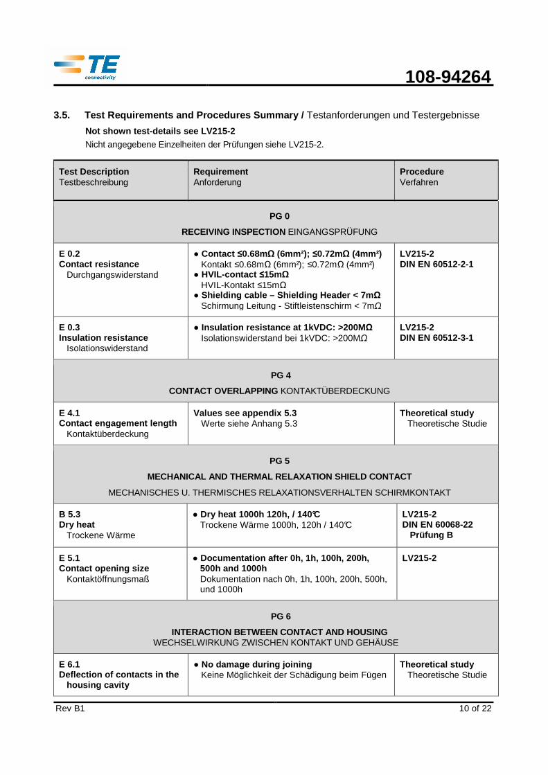
3.5. Test Requirements and Procedures Summary / Testanforderungen und Testergebnisse
Not shown test-details see LV215-2
Nicht angegebene Einzelheiten der Prüfungen siehe LV215-2.
Test Description Testbeschreibung
Requirement Anforderung
Procedure Verfahren
PG 0
RECEIVING INSPECTION EINGANGSPRÜFUNG
E 0.2 Contact resistance
Durchgangswiderstand
Contact ≤0.68mΩ (6mm²); ≤0.72mΩ (4mm²) Kontakt ≤0.68mΩ (6mm²); ≤0.72mΩ (4mm²)
HVIL-contact ≤15mΩ HVIL-Kontakt ≤15mΩ
Shielding cable – Shielding Header < 7m Ω Schirmung Leitung - Stiftleistenschirm < 7mΩ
LV215-2 DIN EN 60512-2-1
E 0.3 Insulation resistance
Isolationswiderstand
Insulation resi stance at 1kVDC: >200M Ω Isolationswiderstand bei 1kVDC: >200MΩ
LV215-2 DIN EN 60512-3-1
PG 4
CONTACT OVERLAPPING KONTAKTÜBERDECKUNG
E 4.1 Contact engagement length
Kontaktüberdeckung
Values see appendix 5.3 Werte siehe Anhang 5.3
Theoretical study Theoretische Studie
PG 5
MECHANICAL AND THERMAL RELAXATION SHIELD CONTACT
MECHANISCHES U. THERMISCHES RELAXATIONSVERHALTEN SCHIRMKONTAKT
B 5.3 Dry heat
Trockene Wärme
Dry heat 1000h 120h, / 140°C Trockene Wärme 1000h, 120h / 140°C
LV215-2 DIN EN 60068-22
Prüfung B
E 5.1 Contact opening size
Kontaktöffnungsmaß
Documentation after 0h, 1h, 100h, 200h, 500h and 1000h Dokumentation nach 0h, 1h, 100h, 200h, 500h, und 1000h
LV215-2
PG 6
INTERACTION BETWEEN CONTACT AND HOUSING WECHSELWIRKUNG ZWISCHEN KONTAKT UND GEHÄUSE
E 6.1 Deflection of contacts in the
housing cavity
No damage during joining Keine Möglichkeit der Schädigung beim Fügen
Theoretical study Theoretische Studie
108-94264
Rev B1
11 of 22
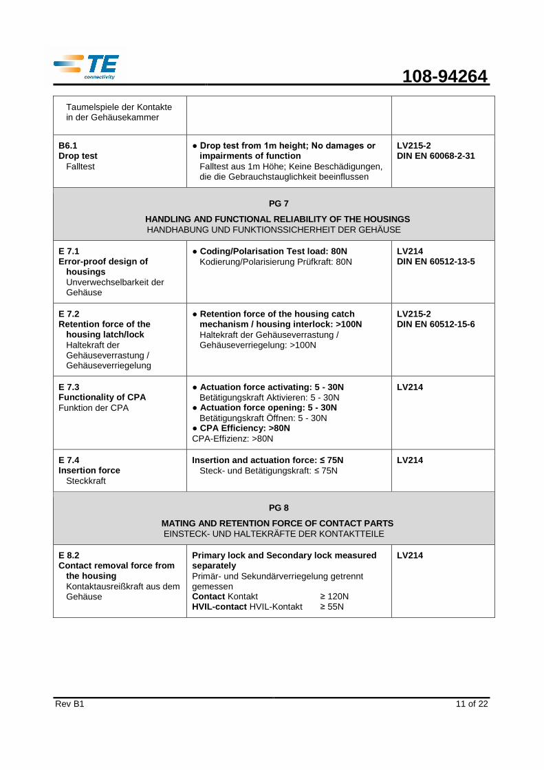
Taumelspiele der Kontakte in der Gehäusekammer
B6.1 Drop test
Falltest
Drop test from 1m height; No damages or impairments of function Falltest aus 1m Höhe; Keine Beschädigungen, die die Gebrauchstauglichkeit beeinflussen
LV215-2 DIN EN 60068-2-31
PG 7
HANDLING AND FUNCTIONAL RELIABILITY OF THE HOUSINGS HANDHABUNG UND FUNKTIONSSICHERHEIT DER GEHÄUSE
E 7.1 Error-proof design of
housings Unverwechselbarkeit der Gehäuse
Coding/Polarisation Test load: 80N Kodierung/Polarisierung Prüfkraft: 80N
LV214 DIN EN 60512-13-5
E 7.2 Retention force of the
housing latch/lock Haltekraft der Gehäuseverrastung / Gehäuseverriegelung
Retention force of the housing catch mechanism / housing interlock: >100N Haltekraft der Gehäuseverrastung / Gehäuseverriegelung: >100N
LV215-2 DIN EN 60512-15-6
E 7.3 Functionality of CPA Funktion der CPA
Actuation force activating: 5 - 30N Betätigungskraft Aktivieren: 5 - 30N Actuation force opening: 5 - 30N Betätigungskraft Öffnen: 5 - 30N CPA Efficiency: >80N CPA-Effizienz: >80N
LV214
E 7.4 Insertion force
Steckkraft
Insertion and actuation force: ≤ 75N Steck- und Betätigungskraft: ≤ 75N
LV214
PG 8
MATING AND RETENTION FORCE OF CONTACT PARTS EINSTECK- UND HALTEKRÄFTE DER KONTAKTTEILE
E 8.2 Contact removal force from
the housing Kontaktausreißkraft aus dem Gehäuse
Primary lock and Secondary lock measured separately Primär- und Sekundärverriegelung getrennt gemessen Contact Kontakt ≥ 120N HVIL-contact HVIL-Kontakt ≥ 55N
LV214

108-94264
Rev B1
12 of 22
PG 9
SKEWED INSERTION ANGLE SCHRÄGSTECKWINKEL
E 9.3 Koshiri Safety
Koshiri-Sicherheit
Live parts must only touch its counter -part while mounting (including insertion chamfers). In case of incorrect insertion of the plug no live parts must be touched. Signal- und stromführende Bauteile dürfen bei Montage nur mit Ihrem Gegenstück berührt werden können. Auch bei fehlerhaftem Einstecken dürfen Kontakte nicht berührt werden.
Theoretical study Theoretische Studie
PG 11
MATING CYCLES STECKHÄUFIGKEIT
B 11.1 Mating cycles
Steckhäufigkeit
50 Cycles 50 Zyklen
Rubbing through the contact surface is not permissible
Durchrieb der Kontaktoberfläche ist nicht zulässig
(MCON1.2 acc. to Spec 108-18782 able for only 20 cycles) (MCON1.2 gem. Spec 108-18782 geeignet für nur 20 Zyklen)
LV214
PG 13
DERATING GEHÄUSEEINFLUSS AUF DIE STROMERWÄRMUNG
E 13.2 Derating with housing
Derating im Gehäuse
Max. temperature at power contacts 180°C Grenztemperatur Leistungskontakte 180°C
Derating see appendix 5.1 Werte siehe Anhang 5.1
LV215-2 DIN EN 60512-5-1/2
PG 17
DYNAMIC LOAD DYNAMISCHE BEANSPRUCHUNG
B 17.2 Dynamic Load; broad-band
random Dynamische Beanspruchung: Breitbandrauschen
Severity 2: “Body” sealed; Details see appendix 5.2 Schärfegrad 2: „Karosserie“ gedichtet; Details siehe Anhang 5.2
Slight wear, surface 0k. Leichte Abnutzung, Oberfläche i.O.
Resistances after testing Durchgangswiderstand nach Test: Contact Kontakt ≤1.36mΩ HVIL-contact HVIL-Kontakt ≤15mΩ Shielding cable – Shielding Header < 7m Ω Schirmung Leitung - Stiftleistenschirm < 7mΩ
LV214 DIN EN 60068-2-64

108-94264
Rev B1
13 of 22
B 17.3 Endurance shock test
Dauerschocken
30g; T=6ms; N=6000 Slight wear, surface ok.
Leichte Abnutzung, Oberfläche i.O. Resistances after testing
Durchgangswiderstand nach Test: Contact Kontakt ≤1.36mΩ HVIL-contact HVIL-Kontakt ≤15mΩ Shielding cable – Shielding Header < 7m Ω
Schirmung Leitung - Stiftleistenschirm < 7mΩ
LV214 DIN EN 60068-2-27
In deviate to LV215 was the validation done with severity 2 and elevated temperature requiremen t (140°C) Abweichend zur LV215 wurde mit Schärfegrad 2 und erhöhter Temperaturanforderung (140°C) validiert
PG18A
CLIMATIC LOAD KÜSTENKLIMABEANSPRUCHUNG
B 18.2 Salt spray test
Salznebeltest
Resistances after Salt spray test, not sealed Durchgangswiderstände nach Salznebeltest, ungedichtet: Contact Kontakt ≤1.36mΩ HVIL-contact HVIL-Kontakt ≤15mΩ Shielding cable - Shielding Header < 7m Ω Schirmung Leitung - Stiftleistenschirm < 7mΩ
LV215-2 DIN EN 60068-2-52
(SG3)
PG20
CLIMATIC LOAD OF HOUSINGS KLIMATISCHE BEANSPRUCHUNG DER GEHÄUSE
B 20.1 Dry heat
Trockene Wärme
Dry heat 120h / 140°C Trockene Wärme 120h / 140°C
LV214 DIN EN 60068-2-2
Prüfung B
B 20.2 Damp heat
Feuchte Wärme
Damp heat 10 days / 40°C / 95% rel. humidity Feuchte Wärme 10 Tage / 40°C / 95% Luftf.
Insulation resistance at 1kVDC: >200M Ω Isolationswiderstand bei 1kVDC: >200MΩ
LV214 DIN EN 60068-2-30 DIN EN 60512-3-1
B 20.3 Climatic cold
Kältelagerung
Climatic cold 48h / -40°C Kältelagerung 48h / -40°C
Plugging / unmating possible at -20°C Stecken / Ziehen bei -20°C möglich
LV214 DIN EN 60068-2-1
B 20.1 Dry heat
Trockene Wärme
Dry heat 48h / 80°C Trockene Wärme 48h / 80°C
LV214
B6.1 Drop test after aging Falltest nach Alterung
Drop test from 1m height; No damages or impairments of function Falltest aus 1m Höhe; Keine Beschädigungen, die die Gebrauchstauglichkeit beeinflussen
LV215-2 DIN EN 60068-2-31

108-94264
Rev B1
14 of 22
PG21
LONG-TERM AGING LANGZEITTEMPERATURLAGERUNG
B 21.1 Long-term aging in dry heat
Langzeittemperaturlagerung
1000h at 140°C; Resistances after aging: 1000h bei 140°C; Durchgangswiderstände nach Alterung: Contact Kontakt ≤1.36mΩ HVIL-contact HVIL-Kontakt ≤15mΩ Shielding cable - Shielding Header < 7m Ω Schirmung Leitung - Stiftleistenschirm < 7mΩ
LV215-2 DIN EN 60068-2-2
PG22B
CHEMICAL RESISTANCE CHEMISCHE BESTÄNDIGKEIT
B 22.1B Chemical Resistance
Chemische Beständigkeit
Application of media for 48h at specified temperature Beaufschlagung für 48h bei spezifizierter Temperatur
No textural or dimensional change, no impairments of function Keine strukturelle oder dimensionelle Verän-derung, keine Beeinträchtigung der Funktion.
Tested chemical Getestete Chemikalien: - Brake fluid Bremsflüssigkeit - Gas Benzin, Super - Diesel Diesel - Biodiesel Biodiesel - Diesel additive Dieselzusatz AdBlue - Engine oil Motoröl 5W-30 - Servo steering oil Servolenkungsöl - Automatic geering oil Automatikgetriebeöl - Antifreeze fluid Kühlerfrostschutz - Battery acid Batteriesäure - Salt solution Tausalzlösung
LV214
PG23
WATERTIGHTNESS WASSERDICHTHEIT
B 19.3 Aging in dry heat
Lagerung bei trockener Wärme
120h at 140°C 120h bei 140°C
DIN EN 60068-2-2 Prüfung B
B 19.1 Temperature shock
Temperaturschock
Period: 144cycles -40°C / +140°C each 15min Dauer: 144 Zyklen -40°C / +140°C, je 15min
DIN EN 60068-2-14
B 23.1 Immersion with pressure
difference Tauchen mit Druckdifferenz
Low pressure: -100mbar, holding time 5min. -500mbar, holding time 5min. Unterdruck: -100mbar, Haltezeit 5min. -500mbar, Haltezeit 5min.
LV214 DIN EN 60512-14-5
108-94264
Rev B1
15 of 22
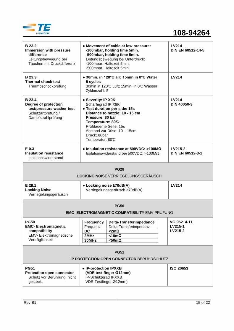
B 23.2 Immersion with pressure
difference Leitungsbewegung bei Tauchen mit Druckdifferenz
Movement of cable at low pressure: -100mbar, holding time 5min. -500mbar, holding time 5min. Leitungsbewegung bei Unterdruck: -100mbar, Haltezeit 5min. -500mbar, Haltezeit 5min.
LV214 DIN EN 60512-14-5
B 23.3 Thermal shock test
Thermoschockprüfung
30min. in 120°C air; 15min in 0°C Water 5 cycles 30min in 120°C Luft; 15min. in 0°C Wasser Zyklenzahl: 5
LV214
B 23.4 Degree of protection
test/pressure washer test Schutzartprüfung / Dampfstrahlprüfung
Severity: IP X9K Schärfegrad IP X9K
Test duration per side: 15s Distance to nozzle: 10 - 15 cm Pressure: 80 bar Temperature: 80°C Prüfdauer je Seite: 15s Abstand zur Düse: 10 – 15cm Druck: 80bar Temperatur: 80°C
LV214 DIN 40050-9
E 0.3 Insulation resistance
Isolationswiderstand
Insulation resi stance at 500VDC: >100M Ω Isolationswiderstand bei 500VDC: >100MΩ
LV215-2 DIN EN 60512-3-1
PG28
LOCKING NOISE VERRIEGELUNGSGERÄUSCH
E 28.1 Locking Noise
Verriegelungsgeräusch
Locking noise ≥70dB(A) Verriegelungsgeräusch ≥70dB(A)
LV214
PG50
EMC- ELECTROMAGNETIC COMPATIBILITY EMV-PRÜFUNG
PG50 EMC- Electromagnetic
compatibility EMV- Elektromagnetische Verträglichkeit
Freque ncy Frequenz
Delta-Transferi mpedance Delta-Transferimpedanz
DC <2mΩ 2MHz <10mΩ 30MHz <50mΩ
VG 95214-11 LV215-1 LV215-2
PG51
IP PROTECTION OPEN CONNECTOR BERÜHRSCHUTZ
PG51 Protection open connector
Schutz vor Berührung; nicht gesteckt
IP-protection IPXXB (VDE test finger Ø12mm) IP-Schutzgrad IPXXB VDE-Testfinger Ø12mm)
ISO 20653

108-94264
Rev B1
16 of 22
3.6. Test sequence / Prüfreihenfolge
The sequence of tests shall be verified by test gro ups as specified.
Die Reihenfolge der Prüfungen müssen gemäß den aufgeführten Prüfgruppen durchgeführt werden.
3.7. Additional Test Procedures / Zusätzliche Testdurchführungen
ADDITIONAL TEST PROCEDURES AND TEST RESULTS ZUSÄTZLICHE TESTDURCHFÜHRUNGEN UND TESTERGEBNISSE
A1 Crimp validation Shielding
Crimpvalidierung Schirmung
Pull out force shield crimp: ≥150N Ausreißkraft Schirmcrimp: ≥150N
Cross section examination: crimp sleeves are well formed, uniform pressing of screening braid Schliffbild: Verformung der Crimphülse i.O., Verpressung der Schirmdrähte i.O.
Crimpresistance initial <2m Ω; after aging <3m Ω Crimpwiderstand initial <2mΩ, nach Alterung ≤3mΩ
TE-Spec. 109-18212
A2 Insulation resistance with temperature load
Isolationswiderstand bei Temperaturbelastung
Measurement vol tage: 1000VDC Messspannung: 1000VDC
Temperature load -40°C till 140°C Temperaturbeanspruchung -40°C bis 140°C
With rising temperature the insulation resistance falls down, with cooling the insulation resistance rises again. Mit zunehmender Temperatur nimmt der Isolationswiderstand ab und steigt mit zunehmender Entlastung wieder an. Insulation resistance, mated
Isolationswiderstand, gesteckt up to bis
100°C 120°C 140°C
> 1GΩ >200MΩ >75MΩ

108-94264
Rev B1
17 of 22
4. QUALITY ASSURANCE PROVISIONS / QUALITÄTSICHERUNGSMAßNAHMEN
4.1. Qualification Testing / Qualifikationsprüfung
The samples shall be prepared in accordance with pr oduct drawings and shall be selected at random from current production.
Die Prüflinge müssen den Zeichnungsunterlagen entsprechen. Sie sind der laufenden Produktion zufällig zu entnehmen.
4.2. Requalification Testing / Requalifikationsprüfung
If changes significantly affecting form, fit, or fu nction depending on the product or manufacturing process, product engineering shall co ordinate requalification testing, consisting of all or part of the original testing sequence as determined by development/product, quality, and reliability engineering.
Falls signifikante Eigenschaftsänderungen der Form, Ausstattung oder Funktion des Produktes, sowie dessen Herstellungsverfahrens vorgenommen werden, muss ein entsprechender Requalifikationstest durchgeführt werden. Dieser kann je nach Festlegung der Entwicklungs- und Qualitätssicherungsabteilung aus einem Teil oder den gesamten ursprünglichen Prüfgruppen bestehen.
A Acceptance / Abnahme
Acceptance is based on verification that the produc t meets the requirements of chapter 4. Failures attributed to equipment, test setup, or op erator deficiencies shall not disqualify the product. When product failure occurs, corrective ac tion shall be taken and samples resubmitted for qualification. Testing to confirm corrective ac tion is required before resubmittal. Die Abnahme basiert auf dem Nachweis, dass das Produkt den Anforderungen nach Kapitel 4 genügt. Abweichungen, die auf Messgeräte, Messanordnungen oder Bedienungsmängel zurückzuführen sind, dürfen nicht zum Entzug der Qualifikation führen. Tritt eine Abweichung auf, müssen korrigierend Maßnahmen ergriffen werden und die Qualifikation ist erneut nachzuweisen. Vor dieser Requalifikation ist durch entsprechende Prüfungen der Erfolg der Korrekturmaßnahme zu bestätigen.
B Quality Conformance Inspection / Prüfung der Qualitätskonformität
The applicable quality inspection plan will specify the sampling acceptable quality level to be used. Dimensional and functional requirements shall be in accordance with the applicable product drawing and this specification.
Die Konformitätsprüfung erfolgt nach dem zugehörigen Qualitätsinspektionsplan, der die annehmbare Qualitätsgrenzlage nach dem Stichprobenumfang festlegt. Maßliche und funktionelle Anforderungen müssen mit den Produktzeichnungen und dieser Spezifikation übereinstimmen.
108-94264
Rev B1
18 of 22
5. APPENDIX / ANHANG
5.1. Housing influence on derating / DERATING IM GEHÄUSE
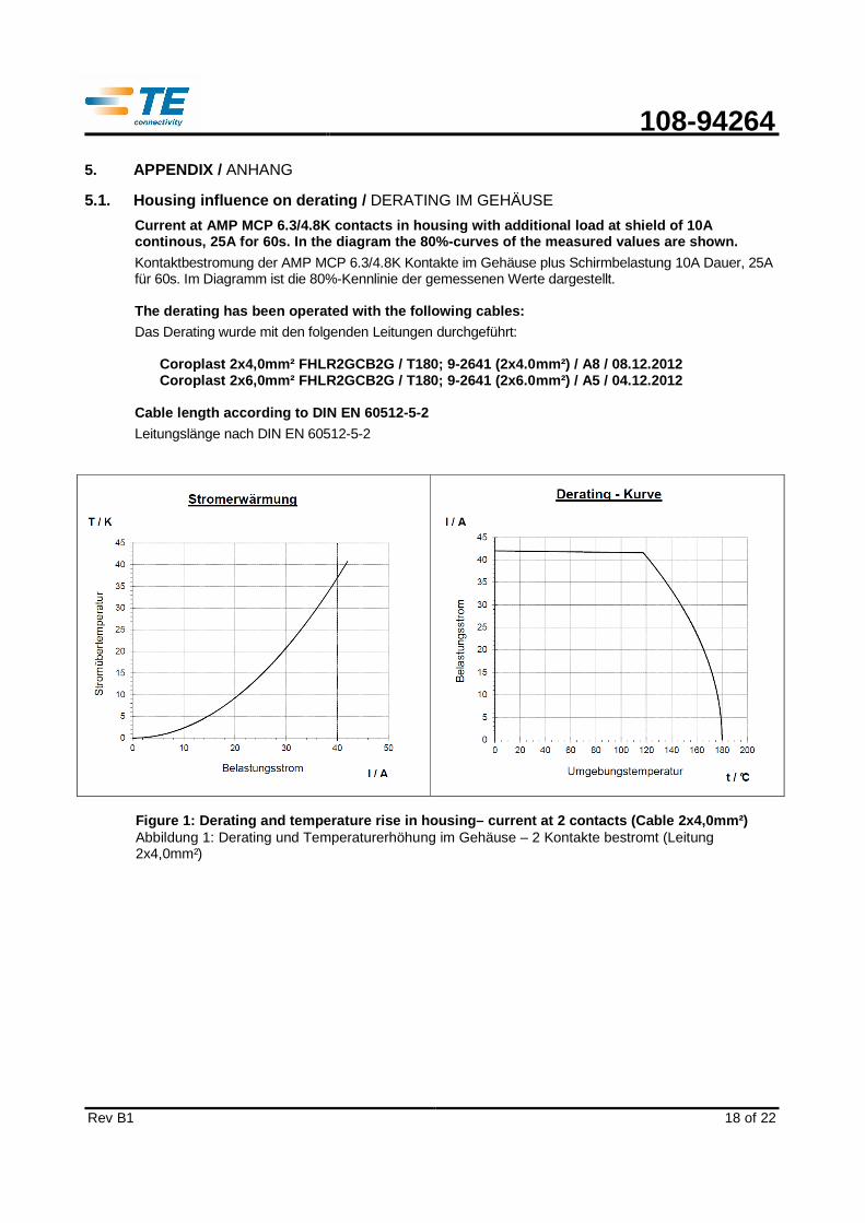
Current at AMP MCP 6.3/4.8K contacts in housing wit h additional load at shield of 10A continous, 25A for 60s. In the diagram the 80%-curv es of the measured values are shown.
Kontaktbestromung der AMP MCP 6.3/4.8K Kontakte im Gehäuse plus Schirmbelastung 10A Dauer, 25A für 60s. Im Diagramm ist die 80%-Kennlinie der gemessenen Werte dargestellt.
The derating has been operated with the following c ables: Das Derating wurde mit den folgenden Leitungen durchgeführt:
Coroplast 2x4,0mm² FHLR2GCB2G / T180; 9-2641 (2x4.0 mm²) / A8 / 08.12.2012 Coroplast 2x6,0mm² FHLR2GCB2G / T180; 9-2641 (2x6.0 mm²) / A5 / 04.12.2012
Cable length according to DIN EN 60512-5-2
Leitungslänge nach DIN EN 60512-5-2
Figure 1: Derating and temperature rise in housing– current at 2 contacts (Cable 2x4,0mm²) Abbildung 1: Derating und Temperaturerhöhung im Gehäuse – 2 Kontakte bestromt (Leitung 2x4,0mm²)
108-94264
Rev B1
19 of 22
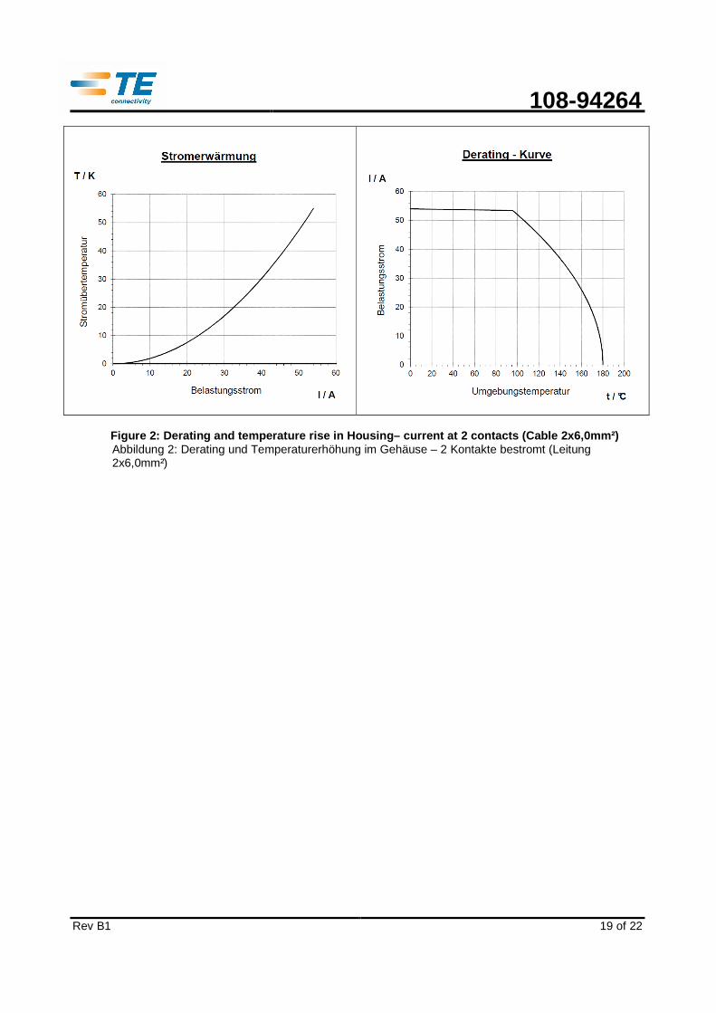
Figure 2: Derating and temperature rise in Housing– current at 2 contacts (Cable 2x6,0mm²)
Abbildung 2: Derating und Temperaturerhöhung im Gehäuse – 2 Kontakte bestromt (Leitung 2x6,0mm²)
108-94264
Rev B1
20 of 22
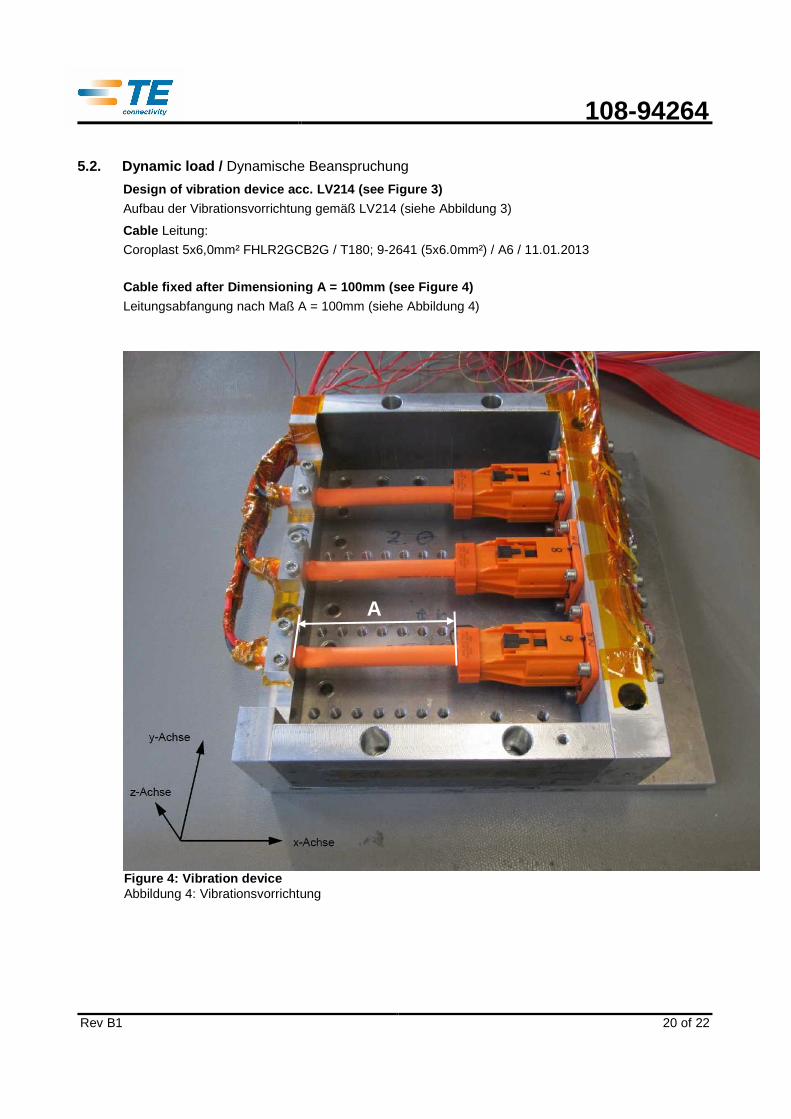
5.2. Dynamic load / Dynamische Beanspruchung
Design of vibration device acc. LV214 (see Figure 3 )
Aufbau der Vibrationsvorrichtung gemäß LV214 (siehe Abbildung 3)
Cable Leitung:
Coroplast 5x6,0mm² FHLR2GCB2G / T180; 9-2641 (5x6.0mm²) / A6 / 11.01.2013
Cable fixed after Dimensioning A = 100mm (see Figur e 4)
Leitungsabfangung nach Maß A = 100mm (siehe Abbildung 4)
Figure 4: Vibration device Abbildung 4: Vibrationsvorrichtung
A
108-94264
Rev B1
21 of 22
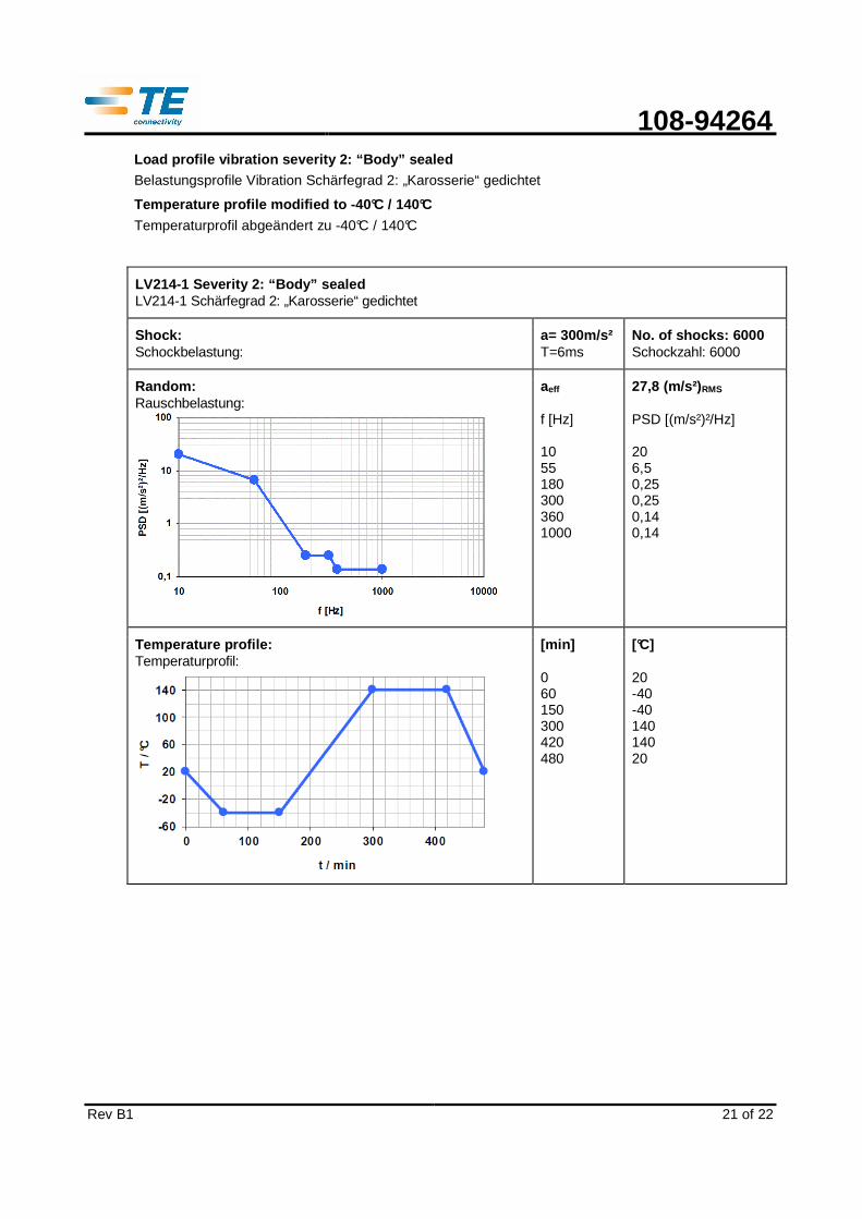
Load profile vibration severity 2: “Body” sealed Belastungsprofile Vibration Schärfegrad 2: „Karosserie“ gedichtet
Temperature profile modified to -40°C / 140°C
Temperaturprofil abgeändert zu -40°C / 140°C
LV214-1 Severity 2: “Body” sealed LV214-1 Schärfegrad 2: „Karosserie“ gedichtet
Shock: Schockbelastung:
a= 300m/s² T=6ms
No. of shocks: 6000 Schockzahl: 6000
Random: Rauschbelastung:
aeff f [Hz] 10 55 180 300 360 1000
27,8 (m/s²) RMS PSD [(m/s²)²/Hz] 20 6,5 0,25 0,25 0,14 0,14
Temperature profile : Temperaturprofil:
[min] 0 60 150 300 420 480
[°C] 20 -40 -40 140 140 20
108-94264
Rev B1
22 of 22
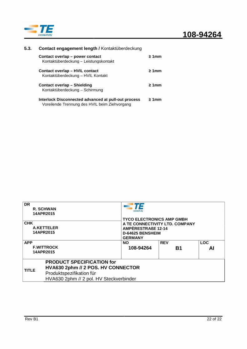
5.3. Contact engagement length / Kontaktüberdeckung
Contact overlap – power co ntact Kontaktüberdeckung – Leistungskontakt
≥ 1mm
Contact overlap – HVIL co ntact Kontaktüberdeckung – HVIL Kontakt
≥ 1mm
Contact overlap – Shielding Kontaktüberdeckung – Schirmung
≥ 1mm
Interlock Disconnected advanced at pull -out process Voreilende Trennung des HVIL beim Ziehvorgang
≥ 1mm
DR
R. SCHWAN 14APR2015
TYCO ELECTRONICS AMP GMBH A TE CONNECTIVITY LTD. COMPANY AMPÈRESTRAßE 12-14 D-64625 BENSHEIM GERMANY
CHK A.KETTELER 14APR2015
APP F.WITTROCK 14APR2015
NO 108-94264
REV B1
LOC AI
TITLE
PRODUCT SPECIFICATION for HVA630 2phm // 2 POS. HV CONNECTOR Produktspezifikation für HVA630 2phm // 2 pol. HV Steckverbinder