108sd and 114sd maintenance manual
TRANSCRIPT

108SD AND 114SD MAINTENANCE MANUAL
Models: 108SD114SD
STI-496-6 (11/16) Published byDaimler Trucks North America LLC
4747 N. Channel Ave.Portland, OR 97217
Printed in U.S.A.

ForewordPerforming scheduled maintenance operations is important in obtaining safe, reliable operation of yourvehicle. A proper maintenance program will also help to minimize downtime and safeguard warranties.
IMPORTANT: The maintenance operations in this manual are not all-inclusive. Also refer to othercomponent and body manufacturers’ instructions for specific inspection and maintenance instruc-tions.
Perform the operations in this maintenance manual at scheduled intervals. Perform the pretrip and post-tripinspections, and daily/weekly/monthly maintenance, as outlined in the vehicle driver’s manual. Majorcomponents, such as engines, transmissions, and rear axles, are covered in their own maintenance andoperation manuals, that are provided with the vehicle. Perform any maintenance operations listed at theintervals scheduled in those manuals. Your Freightliner Dealership has the qualified technicians andequipment to perform this maintenance for you. They can also set up a scheduled maintenance programtailored specifically to your needs. Optionally, they can assist you in learning how to perform thesemaintenance procedures.
IMPORTANT: Descriptions and specifications in this manual were in effect at the time of printing.Freightliner Trucks reserves the right to discontinue models and to change specifications or designat any time without notice and without incurring obligation. Descriptions and specifications containedin this publication provide no warranty, expressed or implied, and are subject to revision and editionswithout notice.
Refer to www.Daimler-TrucksNorthAmerica.com and www.FreightlinerTrucks.com for more information,or contact Daimler Trucks North America LLC at the address below.
Environmental Concerns and RecommendationsWhenever you see instructions in this manual to discard materials, you should attempt to reclaim and recyclethem. To preserve our environment, follow appropriate environmental rules and regulations when disposing ofmaterials.
NOTICE: Parts Replacement ConsiderationsDo not replace suspension, axle, or steering parts (such as springs, wheels, hubs, and steering gears) withused parts. Used parts may have been subjected to collisions or improper use and have undetected structuraldamage.
© 2011-2017 Daimler Trucks North America LLC
All rights reserved. No part of this publication, in whole or in part, may be translated, reproduced, stored in aretrieval system, or transmitted in any form by any means, electronic, mechanical, photocopying, recording, orotherwise, without the prior written permission of Daimler Trucks North America LLC. Daimler Trucks NorthAmerica LLC is a Daimler company.
Daimler Trucks North America LLCService Systems and Documentation (CVI-SSD)
P.O. Box 3849Portland, Oregon 97208-3849
Daimler Trucks North America LLC distributes the following major service publications in paper and electronic(via ServicePro®) formats.
Workshop/ServiceManual
Workshop/service manuals contain service and repair information for all vehiclesystems and components, except for major components such as engines, trans-missions, and rear axles. Each workshop/service manual section is divided intosubjects that can include general information, principles of operation, removal,disassembly, assembly, installation, and specifications.
Maintenance Manual Maintenance manuals contain routine maintenance procedures and intervals forvehicle components and systems. They have information such as lubricationprocedures and tables, fluid replacement procedures, fluid capacities, specifica-tions, and procedures for adjustments and for checking the tightness of fasten-ers. Maintenance manuals do not contain detailed repair or service information.
Driver’s/Operator’sManual
Driver’s/operator’s manuals contain information needed to enhance the driver’sunderstanding of how to operate and care for the vehicle and its components.Each manual contains a chapter that covers pretrip and post-trip inspections,and daily, weekly, and monthly maintenance of vehicle components.Driver’s/operator’s manuals do not contain detailed repair or service information.
Service Bulletins Service bulletins provide the latest service tips, field repairs, product improve-ments, and related information. Some service bulletins are updates to informa-tion in the workshop/service manual. These bulletins take precedence overworkshop/service manual information, until the latter is updated; at that time, thebulletin is usually canceled. The service bulletins manual is available only todealers. When doing service work on a vehicle system or part, check for a validservice bulletin for the latest information on the subject.
IMPORTANT: Before using a particular service bulletin, check the currentservice bulletin validity list to be sure the bulletin is valid.
Parts Technical Bulletins Parts technical bulletins provide information on parts. These bulletins containlists of parts and BOMs needed to do replacement and upgrade procedures.
Web-based repair, service, and parts documentation can be accessed using the following applications on theAccessFreightliner.com website.
ServicePro ServicePro® provides Web-based access to the most up-to-date versions of thepublications listed above. In addition, the Service Solutions feature provides di-agnostic assistance with Symptoms Search, by connecting to a large knowledgebase gathered from technicians and service personnel. Search results for bothdocuments and service solutions can be narrowed by initially entering vehicleidentification data.
PartsPro PartsPro® is an electronic parts catalog system, showing the specified vehicle’sbuild record.
EZWiring EZWiring™ makes Freightliner, Sterling, Western Star, Thomas Built Buses, andFreightliner Custom Chassis Corporation products’ wiring drawings and floatingpin lists available online for viewing and printing. EZWiring can also be ac-cessed from within PartsPro.
IntroductionDescriptions of Service Publications
108SD and 114SD Maintenance Manual, January 2011 I–1

Warranty-related service information available on the AccessFreightliner.com website includes the followingdocumentation.
Recall Campaigns Recall campaigns cover situations that involve service work or replacement ofparts in connection with a recall notice. These campaigns pertain to matters ofvehicle safety. All recall campaigns are distributed to dealers; customers receivenotices that apply to their vehicles.
Field Service Campaigns Field service campaigns are concerned with non-safety-related service work orreplacement of parts. All field service campaigns are distributed to dealers; cus-tomers receive notices that apply to their vehicles.
IntroductionDescriptions of Service Publications
I–2 108SD and 114SD Maintenance Manual, January 2011

For an example of a 108SD and 114SD Maintenance Manual page, see Fig. 1.
f020176
CB
FD E
26
26/1
Transmission
A
02/04/2011
108SD and 114SD Maintenance Manual, April 2011
2. Clean the area around the fill plug, then removethe plug from the side of the gear case.
11/30/2010
A. Full
Fig. 1, Checking Transmission Fluid Level
3. Using your gloved finger or a bent pipe cleaner,check if the fluid is level with the fill opening. See
Clean all dirt from around the end of the fluid fill tubebefore removing the dipstick. Do not allow foreignmatter to enter the transmission. Dirt or foreign mat−ter in the hydraulic system may cause undue wearof transmission parts, make valves stick, and clogpassages.
Transmission Fluid
f260006c
Operating a transmission with the fluid levelhigher or lower than recommended can result intransmission damage. Do not overfill the trans−mission.
Do not mix types and brands of fluid, because ofpossible incompatibility. Do not use fluid addi−tives, friction modifiers, extreme−pressure gearfluids, or multiviscosity lubricants.
Level Check26−01
NOTICE
B. Low
A B
Eaton Fuller
Allison
NOTE: Check the transmission fluid level withthe transmission at operating temperature.
1. Park the vehicle on a level surface, apply theparking brakes, and chock the tires.
Fig. 1.
4. If the fluid level is low, check the transmission forleaks, and correct as needed.
5. If needed, add Eaton−approved fluid until it islevel with the lower edge of the fill opening.Eaton−approved fluid, such as the RoadrangerSAE 50 product, meets the requirements of thePS−164 Rev. 7 lubricant specification. For moreinformation about Eaton lubricant specificationsand suppliers, call 1−800−826−4357 or seew.roadranger.com.
ww−
6. Clean the fill plug, then install it. Tighten the plugas follows:
25 to 35 lbf·ft (34 to 48 N·m) for transmis−sions with 3/4−inch pipe threads.
60 to 75 lbf·ft (81 to 102 N·m) for trans−missions with 3/4−inch pipe threads.
NOTE: For Allison transmissions equipped withan oil level sensor, the transmission fluid levelcan be checked electronically. For more infor−mation, refer to the Allison Transmission web−site, www.allisontransmission.com.
Cold Check
It is important to check the fluid level cold to deter−mine if the transmission has a sufficient amount offluid to be safely operated until a hot check can beperformed.
1. Park the vehicle on a level surface, apply theparking brakes, and chock the tires.
2. Run the engine for at least one minute.
3. Shift from DRIVE to NEUTRAL, and then shift toREVERSE to fill the hydraulic system.
4. Shift to NEUTRAL and allow the engine to idleat 500 to 800 rpm.
5. With the engine running at idle, remove the dip−stick from the tube and wipe it clean.
6. Insert the dipstick into the tube, then remove it.
7. Check the fluid level reading, then repeat thecheck procedure to verify the reading.
If the fluid level is within the COLD RUN band,the transmission may be operated until the fluidis hot enough to perform a hot check.
If the fluid level is not within the COLD RUNband, add or drain fluid as needed to adjust thefluid level to the middle of the COLD RUN band.See Fig. 2.
A. Maintenance Operation Number consists of the Group Number followed by the Sequence NumberB. Group TitleC. Group NumberD. Vehicle NameE. Release DateF. Group Number/Page Number
Fig. 1, Example of a 108SD and 114SD Maintenance Manual Page
IntroductionPage Description
108SD and 114SD Maintenance Manual, January 2011 I–3

Group No. Group Title
00 . . . . . . . . . . . . . . . . . . . . . . General Information01 . . . . . . . . . . . . . . . . . . . . . . . . . . . . . . . . Engine09 . . . . . . . . . . . . . . . . . . . . . . . . . . . . . . Air Intake13 . . . . . . . . . . . . . . . . . . . . . . . . . Air Compressor15 . . . . . . . . . . . . . . . . . . . Alternators and Starters20 . . . . . . . . . . . . . . . . . . . Engine Cooling/Radiator25 . . . . . . . . . . . . . . . . . . . . . . . . . . . . . . . . Clutch26 . . . . . . . . . . . . . . . . . . . . . . . . . . . Transmission31 . . . . . . . . . . . . . Frame and Frame Components32 . . . . . . . . . . . . . . . . . . . . . . . . . . . . Suspension33 . . . . . . . . . . . . . . . . . . . . . . . . . . . . . Front Axle35 . . . . . . . . . . . . . . . . . . . . . . . . . . . . . Rear Axle40 . . . . . . . . . . . . . . . . . . . . . . . . Wheels and Tires41 . . . . . . . . . . . . . . . . . . . . . . . . . . . . . . Driveline42 . . . . . . . . . . . . . . . . . . . . . . . . . . . . . . . . Brakes46 . . . . . . . . . . . . . . . . . . . . . . . . . . . . . . . Steering47 . . . . . . . . . . . . . . . . . . . . . . . . . . . . . . . . . Fuel49 . . . . . . . . . . . . . . . . . . . . . . . . . . . . . . . Exhaust60 . . . . . . . . . . . . . . . . . . . . . . . . . . . . . . . . . . Cab72 . . . . . . . . . . . . . . . . . . . . . . . . . . . . . . . . Doors83 . . . . . . . . . . . . . . . . . Heater and Air Conditioner88 . . . . . . . . . . . . . . Hood, Grille, and Cab Fenders
IntroductionMaintenance Manual Contents
I–4 108SD and 114SD Maintenance Manual, January 2011

Title of Maintenance Operation (MOP) MOP Number
00–01 Determining Scheduled Maintenance Intervals . . . . . . . . . . . . . . . . . . . . . . . . . . . . . . . . . . . . . . . 00–01
00–02 Initial Maintenance (IM) Operations. . . . . . . . . . . . . . . . . . . . . . . . . . . . . . . . . . . . . . . . . . . . . . . . 00–02
00–03 M1 Maintenance Interval Operations. . . . . . . . . . . . . . . . . . . . . . . . . . . . . . . . . . . . . . . . . . . . . . . 00–03
00–04 M2 Maintenance Interval Operations. . . . . . . . . . . . . . . . . . . . . . . . . . . . . . . . . . . . . . . . . . . . . . . 00–04
00–05 M3 Maintenance Interval Operations. . . . . . . . . . . . . . . . . . . . . . . . . . . . . . . . . . . . . . . . . . . . . . . 00–05
00–06 M4 Maintenance Interval Operations. . . . . . . . . . . . . . . . . . . . . . . . . . . . . . . . . . . . . . . . . . . . . . . 00–06
00–07 M5 Maintenance Interval Operations. . . . . . . . . . . . . . . . . . . . . . . . . . . . . . . . . . . . . . . . . . . . . . . 00–07
00–08 Maintenance Sequence and Log . . . . . . . . . . . . . . . . . . . . . . . . . . . . . . . . . . . . . . . . . . . . . . . . . 00–08
00–09 Noise Emission Controls . . . . . . . . . . . . . . . . . . . . . . . . . . . . . . . . . . . . . . . . . . . . . . . . . . . . . . . 00–09
00–10 Verification of Inspections Log . . . . . . . . . . . . . . . . . . . . . . . . . . . . . . . . . . . . . . . . . . . . . . . . . . . 00–10
General Information 00Index, Alphabetical
108SD and 114SD Maintenance Manual, November 2016

Determining ScheduledMaintenance IntervalsPerforming regular maintenance will help ensure thatyour vehicle delivers safe, reliable service and opti-mum performance. A proper maintenance programwill also help to minimize downtime and safeguardwarranties.
To determine the correct maintenance intervals foryour vehicle, you must first determine the type of ser-vice or conditions the vehicle will be operating in.Most vehicles operate in conditions that fall withinone of two schedules. Before placing your vehicle inservice, determine which schedule applies to yourvehicle.
SchedulesSchedule I (severe service) applies to vehicles thattravel up to 6000 miles (10 000 kilometers) annuallyor that operate under severe conditions. Examples ofSchedule I usage are:
• operation on extremely poor roads or wherethere is heavy dust accumulation
• constant exposure to extreme hot, cold, salt air,or other extreme climates
• frequent short-distance travel
• construction-site operation
• city operation such as fire truck and garbagetruck.
• farm operation
Schedule II (short-haul transport) applies to vehiclesthat travel 6000 miles (10 000 kilometers) or moreannually and operate under normal conditions. Ex-amples of Schedule II usage are:
• operation primarily in cities and densely popu-lated areas
• local transport with infrequent freeway travel
• high percentage of stop-and-go travel
Maintenance IntervalsAfter determining the schedule appropriate to yourvehicle, refer to Table 1 to determine when to per-form the Initial Maintenance (IM) and the frequencyof performing subsequent maintenance intervals foreach schedule.
Maintenance OperationsThis manual has an index at the beginning of eachGroup that lists the title and number of each mainte-nance operation (MOP) for that Group. Follow theinstructions under the MOP number to perform therequired maintenance.
In addition to the maintenance operations requiredfor the maintenance interval, perform all daily,weekly, and monthly maintenance operations listed inChapter 21, "Pretrip and Post-Trip Inspections andMaintenance", of the 108SD and 114SD Driver’sManual.
Maintenance Schedules
ScheduleMaintenance Intervals
Maintenance Interval Frequency Mileage km Hours
Schedule I*(severe service)
for vehicles that travel up to6000 miles (10 000 km) annually
Initial Maintenance (IM) first 1000 1600 100
Maintenance 1 (M1) every 1000 1600 100
Maintenance 2 (M2) every 4000 6400 400
Maintenance 3 (M3) every 8000 12 800 800
Maintenance 4 (M4) every 16,000 25 600 1600
Maintenance 5 (M5) every 32,000 51 200 3200
General Information 0000–01 Determining Scheduled Maintenance Intervals
108SD and 114SD Maintenance Manual, November 2016 00/1

Maintenance Schedules
ScheduleMaintenance Intervals
Maintenance Interval Frequency Mileage km Hours
Schedule II(short-haul transport)
for vehicles that travel 6000miles (10 000 km) or more
annually
Initial Maintenance (IM) first 8000 12 000
—
Maintenance 1 (M1) every 8000 12 000
Maintenance 2 (M2) every 16,000 24 000
Maintenance 3 (M3) every 32,000 48 000
Maintenance 4 (M4) every 64,000 96 000
Maintenance 5 (M5) every 128,000 192 000* For Schedule I vehicles equipped with an hourmeter, use maintenance intervals based on hours of operation rather than mileage.
Table 1, Maintenance Schedules
General Information0000–01 Determining Scheduled Maintenance Intervals
108SD and 114SD Maintenance Manual, November 201600/2

Table 2 lists all maintenance operations that are tobe performed at the initial maintenance (IM) interval.Maintenance operation numbers are reference num-bers used to help you find detailed instructions in thismanual on the maintenance operations to be per-
formed. All operations listed in Table 2, along withthe operations listed in the M1 Maintenance IntervalOperations table (Table 3) must be performed tocomplete the initial maintenance (IM).
Initial Maintenance (IM) Operations
Number Title
00-03 Perform All M1 Maintenance Interval Operations
31-01 Frame Fastener Torque Check
32-03 Suspension U-Bolt Torque Check
33-04 Alignment Check
47-01 Fuel Tank Band Nut Tightening
Table 2, Initial Maintenance (IM) Operations
General Information 0000–02 Initial Maintenance (IM) Operations
108SD and 114SD Maintenance Manual, November 2016 00/3

Table 3 lists all maintenance operations that are tobe performed at the M1 maintenance interval. Main-tenance operation numbers are reference numbersused to help you find detailed instructions in thismanual on the maintenance operations to be per-formed.
IMPORTANT: After performing all operations listed inthis table, perform all daily, weekly, and monthlymaintenance operations given in Chapter 21, "Pretripand Post-Trip Inspections and Maintenance", of the108SD and 114SD Driver’s Manual.
M1 Maintenance Interval Operations
Number Title of Maintenance Operation
25-01 Eaton Fuller Clutch Release Bearing Lubrication
25-02 Eaton Fuller Clutch Release Cross-Shaft Lubrication
25-03 Fluid Level Check, Hydraulic Clutch Control
25-05 Clutch Adjustment, Manually Adjusted Clutches
26-01 Transmission Fluid Level Check
26-03 Allison and Eaton Fuller Transmission Breather Check
31-02 Fifth Wheel Inspection
31-03 Fifth Wheel Lubrication
31-04 Trailer Electrical Connector Protection
32-01 Suspension Inspection
32-02 Suspension Lubrication
33-01 Knuckle Pin Lubrication*
33-02 Tie Rod Inspection
33-03 Tie Rod Lubrication*
33-06 Steer Axle Hub Cap Vent Plug Inspection
35-01 Axle Lubricant Level Check
35-02 Axle Breather Check
40-02 Tire Check
41-01 Driveline Inspection
41-02 Driveline Lubrication†
42-01 Air Brake System Valve Inspection
42-02 Bendix Air Dryer Desiccant Replacement‡
42-05 Brake Inspection
42-06 Slack Adjuster Lubrication
42-10 WABCO System Saver Air Dryer Desiccant Cartridge Replacement‡
42-11 Versajust Slack Adjuster Inspection and Lubrication§
46-03 Power Steering Fluid Level Inspection
47-04 LNG Fuel System Inspection
47-07 CNG High-Pressure Fuel Filter Element Replacement¶
60-02 Aerodynamic Component Inspection
72-01 Door Seals Lubrication
General Information0000–03 M1 Maintenance Interval Operations
108SD and 114SD Maintenance Manual, November 201600/4

M1 Maintenance Interval Operations
Number Title of Maintenance Operation
83-01 Air Conditioner Inspection
88-01 Hood Rear Support Lubrication
* For Detroit axles, complete this procedure once a year or at the following applicable interval, whichever comesfirst: every 5000 miles (8000 km) for Schedule I vehicles; or every 25,000 miles (40 000 km) for Schedule II ve-hicles.† For driveline lubrication, the M1 maintenance interval is for Dana Spicer drivelines only; for Meritor drivelines
see the M2 maintenance interval.‡ If equipped with an oil-coalescing desiccant cartridge, replace the cartridge once a year, regardless of mileage.
Otherwise use the M5 maintenance interval.§ Complete this procedure every 25,000 miles (40 225 km), 3 months, or 500 operating hours, whichever comes
first.¶ M1 maintenance interval should be used as a general guideline; the actual frequency of filter element replace-
ment will vary depending on cleanliness of the fuel station system.
Table 3, M1 Maintenance Interval Operations
General Information 0000–03 M1 Maintenance Interval Operations
108SD and 114SD Maintenance Manual, November 2016 00/5

Table 4 lists all maintenance operations that are tobe performed at the M2 maintenance interval. Main-tenance operation numbers are reference numbersused to help you find detailed instructions in this
manual on the maintenance operations to be per-formed. Perform all M1 maintenance interval opera-tions (see Table 3) at the M2 maintenance interval.
M2 Maintenance Interval Operations
Number Title
00-03 Perform All M1 Maintenance Interval Operations
13-01 Air Compressor Inspection
20-01 Radiator Cap Inspection
20-03 Fan Drive Check (Noise Emission Control)
26-02 Eaton Fuller Transmission Fluid Change, and Magnetic Plug Cleaning
41-02 Driveline Lubrication*
42-04 Air Dryer Check
42-07 Meritor Camshaft Bracket Lubrication
46-04 Power Steering Gear Lubrication
46-05 Drag Link Lubrication
47-03 Fuel Filter Replacement
47-06 CNG Fuel System Inspection
47-08 CNG Fuel Cylinder Inspection†
49-01 Exhaust System Inspection (Noise Emission Control)
* For driveline lubrication, the M2 maintenance interval is for Meritor drivelines only; for Dana Spicer drivelinessee the M1 maintenance interval.† The fuel cylinder should be inspected every year or 100,000 miles (160 900 km), whichever comes first.
Table 4, M2 Maintenance Interval Operations
General Information0000–04 M2 Maintenance Interval Operations
108SD and 114SD Maintenance Manual, November 201600/6

Table 5 lists all maintenance operations that are tobe performed at the M3 maintenance interval. Main-tenance operation numbers are reference numbersused to help you find detailed instructions in this
manual on the maintenance operations to be per-formed. Perform all M1 (Table 3) and M2 (Table 4)maintenance interval operations at the M3 mainte-nance interval.
M3 Maintenance Interval Operations
Number Title
00-03 Perform All M1 Maintenance Interval Operations
00-04 Perform All M2 Maintenance Interval Operations
01-01 Engine Drive Belt Inspection
26-04 Allison Transmission Fluid and Filter Change
32-03 Suspension U-Bolt Torque Check
40-01 Wheel Nut Check
42-09 Air Brake Inspection and Leak Test
46-01 Drag Link Inspection
47-05 LNG Vacuum Integrity Test
83-02 HVAC Air Filter Replacement*
* Replace the HVAC air filter at the recommended interval or every six months.
Table 5, M3 Maintenance Interval Operations
General Information 0000–05 M3 Maintenance Interval Operations
108SD and 114SD Maintenance Manual, November 2016 00/7

Table 6 lists all maintenance operations that are tobe performed at the M4 maintenance interval. Main-tenance operation numbers are reference numbersused to help you find detailed instructions in this
manual on the maintenance operations to be per-formed. Perform all M1 (Table 3), M2 (Table 4), andM3 (Table 5) maintenance interval operations at theM4 maintenance interval.
M4 Maintenance Interval Operations
Number Title
00-03 Perform All M1 Maintenance Interval Operations
00-04 Perform All M2 Maintenance Interval Operations
00-05 Perform All M3 Maintenance Interval Operations
09-01 Air Cleaner Element Inspection and Replacement
15-01 Alternator, Battery, and Starter Connections Check
20-02 Radiator Pressure Flush and Coolant Change
31-01 Frame Fastener Torque Check
33-05 Wheel End Inspection, Front Axle*
35-03 Axle Lubricant and Filter Change, and Magnetic Strainer Cleaningand Check†
35-04 Wheel End Inspection, Rear Axle*
42-03 Governor Check
46-02 Power Steering Fluid and Filter Change
47-02 Fuel/Water Separator Element Check and Replacement
60-01 Mirror Folding Check
* Complete this operation at the mileage given for the applicable maintenance schedule, or annually, whichevercomes first.† For Dana Spicer axles, if using a Roadranger synthetic drive axle lubricant, the lubricant change interval is ex-
tended to 180,000 miles (288 000 km).
Table 6, M4 Maintenance Interval Operations
General Information0000–06 M4 Maintenance Interval Operations
108SD and 114SD Maintenance Manual, November 201600/8

Table 7 lists all maintenance operations that are tobe performed at the M5 maintenance interval. Main-tenance operation numbers are reference numbersused to help you find detailed instructions in this
manual on the maintenance operations to be per-formed. Perform all M1 (Table 3), M2 (Table 4), M3(Table 5), and M4 (Table 6) maintenance intervaloperations at the M5 maintenance interval.
M5 Maintenance Interval Operations
Number Title
00-03 Perform All M1 Maintenance Interval Operations
00-04 Perform All M2 Maintenance Interval Operations
00-05 Perform All M3 Maintenance Interval Operations
00-06 Perform All M4 Maintenance Interval Operations
25-04 Fluid Change, Hydraulic Clutch Control
42-02 Bendix Air Dryer Desiccant Replacement
42-08 Foot-Control Valve, E-6, Inspection and Lubrication
42-10 WABCO System Saver Air Dryer Desiccant Cartridge Replacement
Table 7, M5 Maintenance Interval Operations
General Information 0000–07 M5 Maintenance Interval Operations
108SD and 114SD Maintenance Manual, November 2016 00/9

Maintenance Sequence for Schedule I
MaintenanceSequence Maintenance Interval Service Date Miles km Hours
1st IM and M1 1000 1600 100
2nd M1 2000 3200 200
3rd M1 3000 4800 300
4th M1 and M2 4000 6400 400
5th M1 5000 8000 500
6th M1 6000 9600 600
7th M1 7000 11 200 700
8th M1, M2, and M3 8000 12 800 800
9th M1 9000 14 400 900
10th M1 10,000 16 000 1000
11th M1 11,000 17 600 1100
12th M1 and M2 12,000 19 200 1200
13th M1 13,000 20 800 1300
14th M1 14,000 22 400 1400
15th M1 15,000 24 000 1500
16th M1, M2, M3, and M4 16,000 25 600 1600
17th M1 17,000 27 200 1700
18th M1 18,000 28 800 1800
19th M1 19,000 30 400 1900
20th M1 and M2 20,000 32 000 2000
21st M1 21,000 33 600 2100
22nd M1 22,000 35 200 2200
23rd M1 23,000 36 800 2300
24th M1, M2, and M3 24,000 38 400 2400
25th M1 25,000 40 000 2500
26th M1 26,000 41 600 2600
27th M1 27,000 43 200 2700
28th M1 and M2 28,000 44 800 2800
29th M1 29,000 46 400 2900
30th M1 30,000 48 000 3000
31st M1 31,000 49 600 3100
32nd M1, M2, M3, M4, and M5 32,000 51 200 3200
Table 8, Maintenance Sequence for Schedule I
General Information0000–08 Maintenance Sequence and Log
108SD and 114SD Maintenance Manual, November 201600/10

Maintenance Sequence for Schedule II
MaintenanceSequence Maintenance Interval Service Date Miles km
1st IM and M1 8000 12 000
2nd M1 and M2 16,000 24 000
3rd M1 24,000 36 000
4th M1, M2, and M3 32,000 48 000
5th M1 40,000 60 000
6th M1 and M2 48,000 72 000
7th M1 56,000 84 000
8th M1, M2, M3, and M4 64,000 96 000
9th M1 72,000 108 000
10th M1 and M2 80,000 120 000
11th M1 88,000 132 000
12th M1, M2, and M3 96,000 144 000
13th M1 104,000 156 000
14th M1, and M2 112,000 168 000
15th M1 120,000 180 000
16th M1, M2, M3, M4, and M5 128,000 192 000
17th M1 136,000 204 000
18th M1 and M2 144,000 216 000
19th M1 152,000 228 000
20th M1, M2, and M3 160,000 240 000
21st M1 168,000 252 000
22nd M1 and M2 176,000 264 000
23rd M1 184,000 276 000
24th M1, M2, M3, and M4 192,000 288 000
25th M1 200,000 300 000
26th M1 and M2 208,000 312 000
27th M1 216,000 324 000
28th M1, M2, and M3 224,000 336,000
29th M1 232,000 348 000
30th M1 and M2 240,000 360 000
31st M1 248,000 372 000
32nd M1, M2, M3, M4, and M5 256,000 384 000
Table 9, Maintenance Sequence for Schedule II
General Information 0000–08 Maintenance Sequence and Log
108SD and 114SD Maintenance Manual, November 2016 00/11

Noise Emission ControlMaintenance
Federal Law, Part 205:Transportation Equipment NoiseEmission ControlsPart 205, Transportation Equipment Noise EmissionControls, requires the vehicle manufacturer to fur-nish, with each new vehicle, such written instructionsfor the proper maintenance, use, and repair of thevehicle by the ultimate purchaser to provide reason-able assurance of the elimination or minimization ofnoise-emission-control degradation throughout thelife of the vehicle. In compliance with the law, thenoise emission controls maintenance information ineach applicable group of this manual, in conjunctionwith the vehicle workshop manual, provides theseinstructions to owners.
Recommendations forReplacement PartsReplacement parts used for maintenance or repair ofnoise emission controls should be genuine Freight-liner parts. If other than genuine Freightliner partsare used for replacement or repair of componentsaffecting noise emission control, the owner should besure that such parts are warranted by their manufac-turer to be equivalent to genuine Freightliner parts inperformance and durability.
Freightliner Noise EmissionControls WarrantyRefer to the vehicle owner’s warranty informationbook for warranty information concerning noise emis-sion controls.
Tampering with Noise Controls isProhibitedFederal law prohibits the following acts or the caus-ing thereof:
1. The removal or rendering inoperative by any per-son (other than for purposes of maintenance,repair, or replacement) of any device or elementof design incorporated into any new vehicle for
the purpose of noise control, prior to its sale ordelivery to the ultimate purchaser, or while it is inuse.
2. The use of the vehicle after such device or ele-ment of design has been removed or renderedinoperative by any person.
Among those acts presumed to constitute tam-pering are the acts listed below:
A. Removal of engine noise-deadening panels.
B. Removal of cab-tunnel or hood noise-deadening panels.
C. Removal of, or rendering inoperative, the en-gine speed governor so as to allow enginespeed to exceed manufacturer’s specifica-tions.
D. Removal of, or rendering inoperative, the fanclutch, including bypassing the control onany thermostatic fan drive to cause it to op-erate continuously.
E. Removal of the fan shroud.
F. Removal of, or rendering inoperative, ex-haust components, including exhaust pipeclamping.
G. Removal of air intake components.
Maintenance InstructionsScheduled intervals are in the maintenance tables inthis group. A "Verification of Inspections Log (Groups01, 20, and 49)" follows, and should be filled in eachtime noise emission controls on the vehicle are main-tained or repaired.
General Information0000–09 Noise Emission Controls
108SD and 114SD Maintenance Manual, November 201600/12

Verification of Inspections LogThe "Verification of Inspections Log" should be filledout each time the vehicle’s noise emission controlsare maintained or repaired.
Verification of Inspections Log, Group 20
Verification of Inspections Log, Group 20, Engine Cooling/Radiator
Date Mileage Item Cost Maintenance Facility
Verification of Inspections Log, Group 49
Verification of Inspections Log, Group 49, Exhaust
Date Mileage Item Cost Maintenance Facility
General Information 0000–10 Verification of Inspections Log
108SD and 114SD Maintenance Manual, November 2016 00/13

Title of Maintenance Operation (MOP) MOP Number
Engine Drive Belt Inspection. . . . . . . . . . . . . . . . . . . . . . . . . . . . . . . . . . . . . . . . . . . . . . . . . . . . . . . . . . 01–01
Safety Precautions. . . . . . . . . . . . . . . . . . . . . . . . . . . . . . . . . . . . . . . . . . . . . . . . . . . . . . . . . . . . . . . . . 01–00
Engine 01Index, Alphabetical
108SD and 114SD Maintenance Manual, September 2015

01–00 Safety PrecautionsSafety Precautions in this section apply to allprocedures within this group.
DANGERWhen working on the vehicle, shut down the en-gine, set the parking brake, and chock the tires.Before working under the vehicle, always placejack stands under the frame rails to ensure thevehicle cannot drop. Failure to follow these stepscould result in serious personal injury or death.
01–01 Engine Drive BeltInspection
Worn or loose drive belts may cause engine over-heating or loss of alternator power. Excessive ten-sion, or too little tension on the belt may result in ex-cessive and premature belt wear or accessorybearing failure. Serpentine belts are retained by abelt tensioner that requires no tension adjustment.Replace the drive belt if any conditions describedbelow are found. To inspect a belt, gently twist it toview the belt sidewalls and bottom.
IMPORTANT: For EPDM rubber drive belts, donot rely on cracking as an indicator of belt wear.EPDM rubber drive belts resist cracking betterthan Neoprene belts. A better indicator of wearon EPDM belts is material loss.
Belt and Pulley Inspection1. Check the belt contact surfaces for damage. See
Fig. 1.
2. Inspect the belt for glazing. Glazing is repre-sented by shiny sidewalls, and is caused by fric-tion created when a loose belt slips in the pul-leys. It can also be caused by oil or grease onthe pulleys.
3. Check the belt for ply separation. Oil, grease, orbelt dressing can cause the belt to fall apart inlayers. Repair any oil or coolant leaks that areaffecting the belts before replacing the drivebelts. Do not use belt dressing on any belt.
4. Check the belt for a jagged or streaked sidewall.Jagged or streaked sidewalls are the result of
foreign objects, such as sand or gravel in thepulley, or a rough pulley surface.
5. Check for tensile breaks (breaks in the cordbody). Cuts in a belt are usually caused by for-eign objects in the pulley, or by prying or forcingthe belt during removal or installation.
6. Check for uneven ribs on serpentine belts. For-eign objects in the pulley will erode the under-cord ribs, causing the belt to lose its grippingpower.
7. For EPDM belts, check the belt for material loss,which causes the belt to seat further down in thepulley and to ride directly on the pulley tips. SeeFig. 2.
8. For Neoprene belts, check the drive belts forcracks. Small irregular cracks are usually signsof an old belt.
9. Inspect the pulleys for excessive play or wobble.Excessive play or wobble indicates a failure ofthe pulley bearing. Check for belt squealing orsqueaking. Replace the bearings as necessary.
NOTE: If it is difficult to distinguish the locationof a supposed bearing noise, place a stetho-scope on the component being checked, not thepulley, to isolate the area from outside interfer-ence.
10. Inspect all pulleys for foreign objects, oil, orgrease in the grooves.
Belt Tensioner InspectionBelt tension is automatically adjusted with a springtensioner. See Fig. 3 and Fig. 4. Check that the ten-sioner is holding tension on the belt by inserting theend of a breaker bar in the 1/2-inch square hole onthe forward face of the tensioner, and rotating thetensioner away from the belt. When the breaker baris slowly released, the tensioner should return to itsoriginal position. The tensioner should rotatesmoothly with no binding. If not, see Group 01 of the108SD and 114SD Workshop Manual for replace-ment instructions.
Engine 01
108SD and 114SD Maintenance Manual, September 2015 01/1

01/18/2010 f151148
1 2 3
4 5 6
7 8
1. Abrasion2. Chunk-out3. Improper Install
4. Cracking5. Pilling6. Uneven Rib Wear
7. Misalignment8. Gravel Penetration
Fig. 1, Damaged Belts
Engine01
108SD and 114SD Maintenance Manual, September 201501/2

09/21/2009 f012181
A
B
C
A. New BeltB. Worn BeltC. Material loss results in belt riding directly on pulley tips.
Fig. 2, Six-Rib Serpentine Belt (cross section view)
01/19/2012 f012189
1
2
6
4
5
3
1. Front Belt2. Rear Belt3. AC Compressor
4. Spring Tensioner5. Fan Clutch6. Water Pump
Fig. 3, DD 13/15/16 Drive Belt Routing
01/24/2011 f012192
1
2
3
4
5
6
1. Spring Tensioner2. Alternator Pulley3. AC Compressor
4. Fan Clutch5. Drive Belt6. Crank Shaft Pulley
Fig. 4, Cummins ISC/ISL Drive Belt Routing
Engine 01
108SD and 114SD Maintenance Manual, September 2015 01/3

Title of Maintenance Operation (MOP) MOP Number
Air Cleaner Element Inspection and Replacement . . . . . . . . . . . . . . . . . . . . . . . . . . . . . . . . . . . . . . . . . . 09–01
Air Intake 09Index, Alphabetical
108SD and 114SD Maintenance Manual, November 2014

09–01 Air Cleaner ElementInspection andReplacement
Restriction of air flow through the air cleaner elementis measured at the tap in the air cleaner outlet.Check the restriction indicator at the air cleaner or inthe cab if the vehicle is equipped with a dash-mounted restriction gauge.
Vehicles may be equipped with either a manual-resetrestriction indicator with graduations (Fig. 1), or ago/no-go restriction indicator without graduations(Fig. 2).
1. Inspect the air restriction indicator to see if airrestriction equals or exceeds the maximum al-lowable restriction. For instructions, see the ve-hicle Driver’s Manual.
NOTICEDo not use aftermarket air-cleaner elements. After-market air-cleaner elements may not seal thehousing correctly, which can lead to engine dam-age and potentially the loss of warranty. When re-placing an air-cleaner element, use only the partlisted in PartsPro for the serial number of the ve-hicle.
2. If necessary, replace the air cleaner element. Forair cleaner element replacement instructions, seeGroup 09 of the vehicle Workshop Manual.
3. Inspect the air cleaner housing for cracks, leaks,or any other damage. If the air cleaner housingor element is damaged, replace it.
4. Reset the air restriction indicator.
5. Each time the air cleaner housing is replaced,perform the procedures in MOP 13–01.
08/07/2007 f090452
Fig. 1, Manual-Reset Air Restriction Indicator,Graduated
04/08/2005 f090431
Fig. 2, Manual-Reset Air Restriction Indicator, Go/No-Go
Air Intake 09
108SD and 114SD Maintenance Manual, November 2014 09/1

Title of Maintenance Operation (MOP) MOP Number
Air Compressor Inspection . . . . . . . . . . . . . . . . . . . . . . . . . . . . . . . . . . . . . . . . . . . . . . . . . . . . . . . . . . . 13–01
Safety Precautions. . . . . . . . . . . . . . . . . . . . . . . . . . . . . . . . . . . . . . . . . . . . . . . . . . . . . . . . . . . . . . . . . 13–00
Air Compressor 13Index, Alphabetical
108SD and 114SD Maintenance Manual, September 2015

13–00 Safety PrecautionsSafety Precautions in this section apply to allprocedures within this group.
DANGERWhen working on the vehicle, shut down the en-gine, set the parking brake, and chock the tires.Before working under the vehicle, always placejack stands under the frame rails to ensure thevehicle cannot drop. Failure to follow these stepscould result in serious personal injury or death.
13–01 Air CompressorInspection
1. Inspect the air compressor intake hoses andconnections at the air intake and air compressorfor physical damage. If needed, change thehoses, and/or tighten or replace the connections.
2. Inspect the coolant supply and return lines fortight connections. Tighten the connections andreplace the lines and fasteners if needed.
3. For the air governor, inspect the piping and con-nections for leaks. Replace gaskets and faultycomponents as needed.
Air Compressor 13
108SD and 114SD Maintenance Manual, September 2015 13/1

Title of Maintenance Operation (MOP) MOP Number
Alternator, Battery, and Starter Connections Check . . . . . . . . . . . . . . . . . . . . . . . . . . . . . . . . . . . . . . . . . 15–01
Safety Precautions. . . . . . . . . . . . . . . . . . . . . . . . . . . . . . . . . . . . . . . . . . . . . . . . . . . . . . . . . . . . . . . . . 15–00
Alternators and Starters 15Index, Alphabetical
108SD and 114SD Maintenance Manual, September 2015

15–00 Safety PrecautionsSafety Precautions in this section apply to allprocedures within this group.
DANGERWhen working on the vehicle, shut down the en-gine, set the parking brake, and chock the tires.Before working under the vehicle, always placejack stands under the frame rails to ensure thevehicle cannot drop. Failure to follow these stepscould result in serious personal injury or death.
15–01 Alternator, Battery, andStarter ConnectionsCheck
WARNINGBatteries generate explosive gas as a by-productof their chemical process. Do not smoke whenworking around batteries. Put out all flames andremove any source of sparks or intense heat inthe vicinity of the battery compartment. Make surethe battery compartment has been completelyvented before disconnecting or connecting thebattery cables.
Battery acid is extremely harmful if splashed inthe eyes or on the skin. Always wear a face shieldand protective clothing when working aroundbatteries.
1. Disconnect the batteries.
2. Check the tightness of the alternator fasteners;tighten as needed. For torque values, see Group15 of the 108SD and 114SD Workshop Manual.
3. Inspect the alternator drive belt for cracking,glazing, and wear; see Group 01. Replace thebelt if it shows any of these symptoms.
NOTE: Engines equipped with a serpentine belthave automatic belt tensioners, and do not re-quire belt tension adjustment.
4. Check the alternator wiring for missing insulation,kinks, and heat damage. Replace or repair asneeded.
5. Check that all electrical connections at the alter-nator and starter are free of corrosion. Clean andtighten all charging system electrical connec-tions, including the connections at the starter B+terminal and ground terminals, the magneticswitch, and where the alternator charging cablesterminate. Apply red dielectric enamel to all ex-posed connections.
6. Inspect the battery retainer assembly or hold-downs, and the battery box. Replace worn ordamaged parts. Remove any corrosion with awire brush, and wash with a weak solution ofbaking soda and water. Flush with clean water,and dry. Paint the retainer assembly if needed, toprevent rusting.
7. Check that foreign material, such as road debris,is removed from the battery box.
8. Inspect and clean the battery cables, terminals,and clamps as follows. See Group 54 of the108SD and 114SD Workshop Manual for trouble-shooting instructions, and for adjustment, repair,and replacement instructions.
8.1 Inspect the battery cables, and replaceany that are damaged.
8.2 Clean and tighten the battery groundcables, terminals, and clamps. Clean thecable connector terminals with a wirebrush.
8.3 Connect the cables to the batteries andtighten them to the torque specificationslisted on the battery, generally 10 to 15lbf·ft (14 to 20 N·m).
8.4 Coat the battery terminals and cable con-nections with dielectric grease.
9. Check the connections at the power net distribu-tion box. Clean and protect the power cableswith dielectric enamel as necessary.
Alternators and Starters 15
108SD and 114SD Maintenance Manual, September 2015 15/1

Title of Maintenance Operation (MOP) MOP Number
Fan Drive Check (Noise Emission Control) . . . . . . . . . . . . . . . . . . . . . . . . . . . . . . . . . . . . . . . . . . . . . . . 20–03
Radiator Cap Inspection. . . . . . . . . . . . . . . . . . . . . . . . . . . . . . . . . . . . . . . . . . . . . . . . . . . . . . . . . . . . . 20–01
Radiator Pressure Flush and Coolant Change. . . . . . . . . . . . . . . . . . . . . . . . . . . . . . . . . . . . . . . . . . . . . 20–02
Safety Precautions. . . . . . . . . . . . . . . . . . . . . . . . . . . . . . . . . . . . . . . . . . . . . . . . . . . . . . . . . . . . . . . . . 20–00
Engine Cooling/Radiator 20Index, Alphabetical
108SD and 114SD Maintenance Manual, September 2015

20–00 Safety PrecautionsSafety Precautions in this section apply to allprocedures within this group.
DANGERWhen working on the vehicle, shut down the en-gine, set the parking brake, and chock the tires.Before working under the vehicle, always placejack stands under the frame rails to ensure thevehicle cannot drop. Failure to follow these stepscould result in serious personal injury or death.
20–01 Radiator Cap Inspection
WARNINGDo not remove or loosen the radiator cap until theengine and cooling system have completelycooled. Use extreme care when removing the cap.A sudden release of pressure from removing thecap prior to the system cooling can result in asurge of scalding coolant that could cause seri-ous personal injury.
NOTICEThe radiator cap currently installed may not be thesame one installed when the vehicle was built. Ifthe radiator cap must be replaced, make sure thatit is the correct cap for the cooling system of thevehicle. Because the radiator cap pressure ratingaffects the operating temperature of the engine,installing an improperly rated radiator cap mayhave adverse effects on the cooling system, andengine operating temperatures. This could causepremature engine wear or damage.
1. Using a radiator-cap tester, check the pressurecap to see if it maintains pressure to within 10percent of the pressure rating marked on thecap. If it doesn’t, replace the cap. Make sure thatthe replacement radiator cap is correctly rated forthe cooling system of the vehicle.
2. There is a second valve in the radiator cap thatopens under vacuum. This prevents the collapseof hoses and other parts that are not internallysupported when the system cools. Inspect thevacuum-relief valve to be sure it is not stuck.
3. Make sure that the cap seals properly on thecoolant filler neck seat, and that the radiator capgasket is not damaged. On vehicles withscrew-on caps with O-rings, make sure that theO-ring is not cracked or deteriorated. Replacethe cap if the gasket shows deterioration or dam-age.
20–02 Radiator Pressure Flushand Coolant Change
NOTE: For additional instructions on cleaningand flushing the cooling system, see the enginemaintenance and operation manual.
WARNINGDrain the coolant only when the coolant and en-gine are cool. Draining it when these are hot couldcause severe personal injury due to scalding.
1. Drain the radiator, as follows.
1.1 Place a large container under the radia-tor.
1.2 Remove the surge tank cap.
1.3 Open the petcock at the bottom of theradiator to drain the engine coolant.
2. Disconnect the radiator inlet and outlet hose con-nections.
3. Flush the radiator, as follows.
3.1 Attach a flushing gun nozzle to the radia-tor outlet.
3.2 Add water to the radiator until it is full.
NOTICEWhen flushing the radiator, do not apply morethan 20 psi (138 kPa) air pressure. Excessive pres-sure can damage the radiator or heater core.
3.3 Apply no more than 20 psi (138 kPa) airpressure intermittently to help dislodgesediment buildup in the core.
4. Drain the radiator, then flush the radiator untilclean water flows from it. Remove the flushinggun.
5. Close the petcock.
Engine Cooling/Radiator 20
108SD and 114SD Maintenance Manual, September 2015 20/1

6. Using clamps, connect the hoses to the radiator.Tighten the clamps 33 to 38 lbf·in (370 to 430N·cm).
IMPORTANT: On vehicles with EPA10 compliantengines, the coolant capacity varies dependingon the engine and accessory installation. Afterservicing the cooling system, always verify thatthe coolant level is between the MIN and MAXlines on the surge tank.
7. Fill the cooling system with approved coolant.Refer to the engine manufacturer’s service litera-ture for specific coolant information. Refer toPartsPro (module 103) for coolant system ca-pacities.
20–03 Fan Drive Check (NoiseEmission Control)
BorgWarner Kysor® K26RA andK22RA Fan Drives1. Check the fan for missing, cracked, chipped, or
damaged blades. Tighten loose components. Re-place damaged fans if necessary.
2. Check for adequate clearance around the fan.The fan should be centered in the shroud to pre-vent contact between the fan and the shroud.
3. Check the fan belt for proper alignment and con-dition. If the belt is worn or frayed, replace thebelt.
4. Verify the fan drive engagement. With the engineand ignition key switch off, apply at least 90 psi(620 kPa) to the clutch; the fan should rotatefreely. Remove air pressure from the clutch andthe fan should not rotate.
5. With the fan drive disengaged, check for airleaks at the front of the clutch and between theclutch and the drive hub. If an air leak is de-tected, the clutch seals and hub must be in-spected for wear or damage. If necessary, theseals of the clutch can be replaced with a Kysorrebuild kit. If inspection of the hub indicates ex-cessive wear, rebuild the hub using a hub rebuildkit from Kysor.
6. Any time the clutch is removed for repair or re-placement, the pulley hub and bearings should
be inspected for play, roughness, or damage.Hub bearing service kits are available fromKysor.
7. Check the lining with the System Alert Tool™. Ifthe lining is worn, install the appropriate lining kit.A lining that is prematurely worn is caused bycontrol air supply problems. Inspect and correctthe vehicle control system before placing the ve-hicle back in service.
8. Check the air line entry and routing at the frontor rear of the fan drive. Look for cracked, dam-aged, or improperly routed air lines. Make surethe connections are tight and that there are noair leaks.
9. Check the electrical connections at the solenoidvalve, which is typically mounted to the frontwall.Check the exhaust port for restrictions. If a re-striction is found, clear it.
Horton DriveMaster® Fan ClutchNOTE: If any part of the fan clutch needs to berepaired or replaced after performing the checksbelow, see Group 20 of the 108SD and 114SDWorkshop Manual.
WARNINGMake sure the batteries are disconnected beforechecking the fan clutch. If the engine starts duringthis procedure, the fan could engage, which couldresult in serious personal injury.
1. Disconnect the batteries at the negative termi-nals. Drain all air from the air system. Ifequipped with an air starter, drain the air starterreservoir.
2. Inspect the electrical connections and wires tothe fan clutch solenoid. Secure the connection ifloose; replace wires and connectors if damaged.
3. Clean the fan clutch air solenoid valve filter, ifequipped.
3.1 Unscrew the fan clutch solenoid valve airfilter assembly, and remove the filter ele-ment.
3.2 Clean the filter element with cleaning sol-vent.
3.3 Using a clean, lint-free cloth, wipe off anyexcess solvent.
Engine Cooling/Radiator20
108SD and 114SD Maintenance Manual, September 201520/2

3.4 Reassemble the clutch valve solenoid airfilter assembly, and install it on the ve-hicle.
4. Visually check the fan for bent, cracked, or dam-aged blades. Replace if damaged. Check for ad-equate clearance between the fan and othercomponents.
5. Check the fan belt for wear, tension, and align-ment. Correct, if necessary.
6. Check for wear on the friction facing. Replacethe friction facing if it is worn to a 3/16-inch (4.8-mm) thickness or less. Also check the facing forsigns of oil contamination or burn marks. If evi-dence of oil or burn marks are found, replace thefriction facing.
7. Connect the battery cables. Start the engine, andcharge the air system to 120 psi (827 kPa).Manually engage and disengage the fan clutch.
Check the fan and the fan clutch from a dis-tance. Look for vibration, fan blade contact, fanclutch slippage, and overall fan clutch operation.
If the fan clutch does not operate correctly, seeGroup 20 of the 108SD and 114SD WorkshopManual for troubleshooting and repair proce-dures.
8. With the air system charged to 120 psi (827kPa), check for air leaks at the fan clutch, sole-noid valve, air hoses, and fittings from the fan
clutch to the air tanks. Use a suitable listeningdevice, and, as needed, a soapy water solution.
9. If a leak is detected, remove the fan blade. In-stall a new seal kit. See Group 20 of the 108SDand 114SD Workshop Manual for repair proce-dures.
10. Check the fan drive for discoloration or any othersigns of slipping or overheating.
NOTE: The fan clutch may slip if the air supplypressure is below 70 psi (483 kPa) or if there isa leak inside the fan clutch. Any leak must beremedied.
11. Check the fan clutch bearings.
11.1 Turn the fan in both directions and feelfor worn hub bearings.
11.2 If possible, remove the drive belt andcheck for worn sheave bearings by turn-ing the sheave in both directions.
11.3 If either the hub or sheave bearings areworn, replace them using a Horton Drive-Master Super Kit.
For repair kit information, see Horton’swebsite, www.hortonww.com.
For instructions, see Group 20 of the108SD and 114SD Workshop Manual.
Approved Coolants
Manufacturer Coolant Type
Cummins Fleetguard® Compleat Premix Premixed solution with supplement additives
Detroit Diesel Detroit Diesel Power Cool Premixed solution with supplement additives
Old World Industries Fleet Charge™ With supplement additives
Table 1, Approved Coolants
Engine Cooling/Radiator 20
108SD and 114SD Maintenance Manual, September 2015 20/3

Title of Maintenance Operation (MOP) MOP Number
Clutch Adjustment, Manually Adjusted Clutches. . . . . . . . . . . . . . . . . . . . . . . . . . . . . . . . . . . . . . . . . . . . 25–05
Eaton Fuller Clutch Release Bearing Lubrication . . . . . . . . . . . . . . . . . . . . . . . . . . . . . . . . . . . . . . . . . . . 25–01
Eaton Fuller Clutch Release Cross-Shaft Lubrication. . . . . . . . . . . . . . . . . . . . . . . . . . . . . . . . . . . . . . . . 25–02
Fluid Change, Hydraulic Clutch Control. . . . . . . . . . . . . . . . . . . . . . . . . . . . . . . . . . . . . . . . . . . . . . . . . . 25–04
Fluid Level Check, Hydraulic Clutch Control . . . . . . . . . . . . . . . . . . . . . . . . . . . . . . . . . . . . . . . . . . . . . . 25–03
Safety Precautions. . . . . . . . . . . . . . . . . . . . . . . . . . . . . . . . . . . . . . . . . . . . . . . . . . . . . . . . . . . . . . . . . 25–00
Clutch 25Index, Alphabetical
108SD and 114SD Maintenance Manual, September 2015

25–00 Safety PrecautionsSafety Precautions in this section apply to allprocedures within this group.
DANGERWhen working on the vehicle, shut down the en-gine, set the parking brake, and chock the tires.Before working under the vehicle, always placejack stands under the frame rails to ensure thevehicle cannot drop. Failure to follow these stepscould result in serious personal injury or death.
25–01 Eaton Fuller ClutchRelease BearingLubrication
If the vehicle is not equipped with a maintenance-free sealed clutch release bearing, lubricate the bear-ing as follows:
1. Park the vehicle on a level surface. Apply theparking brakes, and chock the rear tires.
2. Remove the clutch inspection plate.
NOTE: For lubricating the release bearing,Eaton Fuller recommends a lithium-base greasethat can operate up to at least 325°F (163·C)and meets the NLGI grade two or three specifi-cation.
3. Wipe the dirt away from the grease fitting. SeeFig. 1. Use a low-pressure-type grease gunequipped with the recommended grease, andlubricate the bearing until excess grease purgesfrom the rear of the release bearing (toward thetransmission).
NOTICEDo not over-lubricate the clutch release bearing.Over-lubrication could contaminate the clutch in-ternally, causing clutch slippage and prematurefailure. Do not use chassis grease or multipurposelubricants.
4. Wipe off excess grease and apply it to both theyoke finger and sleeve bushing contact points.See Fig. 2.
5. Install the clutch inspection plate.
f250081a05/27/93
NOTE: Some clutch release bearings are equipped witha lubrication extension that protrudes from the clutchhousing.
Fig. 1, Release Bearing Grease Fitting
11/29/2010 f250680
12
3
1. Release Bearing2. Sleeve Bushing Contact Point3. Yoke Finger Contact Points
Fig. 2, Grease the Contact Points
Clutch 25
108SD and 114SD Maintenance Manual, September 2015 25/1

25–02 Eaton Fuller ClutchRelease Cross-ShaftLubrication
IMPORTANT: This maintenance operation per-tains only to vehicles equipped with mechanical(not hydraulic) linkages.
The clutch release cross-shaft is equipped with twogrease fittings in the transmission clutch housing.See Fig. 3. Wipe the dirt from the grease fittings andlubricate with multipurpose chassis grease.
25–03 Fluid Level Check,Hydraulic Clutch Control
WARNINGUse only approved fluid (DOT 4 brake fluid) in thehydraulic clutch control system. Do not mix differ-ent types of brake fluid. The wrong fluid will dam-age the rubber parts of the system, causing lossof clutch function and the risk of serious personalinjury.
NOTICEDo not allow the fluid level in the reservoir to gobelow the MIN line. If air enters the system, the
hydraulic system will not operate correctly, andthe clutch could be damaged.
If the fluid level is below the MIN line, fill the reser-voir with new DOT 4 brake fluid from a tightly sealedcontainer until the level reaches the MAX line. SeeFig. 4.
25–04 Fluid Change, HydraulicClutch Control
Replace the hydraulic clutch control fluid to ensureclutch function is reliable and correct. It can bechanged by pressure bleeding or manual bleeding.Pressure bleeding can be done by one person andmanual bleeding requires two.
f260146a05/27/93
NOTE: There are grease fittings on both the left andright side of the housing.
Fig. 3, Cross-Shaft Grease Fitting
10/25/2011 f250691
Fig. 4, Reservoir, Hydraulic Clutch Control
Clutch25
108SD and 114SD Maintenance Manual, September 201525/2

WARNINGHydraulic clutch control fluid (DOT 4 brake fluid)is hazardous. It may be a skin irritant and cancause blindness if it gets in your eyes. Alwayswear safety glasses when handling it or bleedinghydraulic lines. If you get it on your skin, wash itoff as soon as possible.
NOTICEDo not spill hydraulic clutch control fluid on thecab paint. Clean it off immediately if any is spilled.Brake fluid can damage paint.
IMPORTANT: The pressure line must slope con-tinuously downward between the master andslave cylinders. On some vehicles, the securingclamps may need to be removed to achieve thisand allow the air to be purged.
Pressure BleedingNOTE: A bleeder system (J-29532) and a bleedadaptor (J-35798) for the fluid reservoir areavailable through SPX Kent-Moore Tools andmay be used to complete the following proce-dure. To order these parts, call Kent-Moore at1-800-328-6657.
1. Park the vehicle on a level surface, shut downthe engine, and set the parking brake. Chock thetires and raise the hood.
2. Prepare the pressure bleeding equipment ac-cording to the manufacturer’s instructions. Usenew DOT 4 brake fluid from a tightly sealed con-tainer. Pressurize the bleeder system to 15 psi(103 kPa).
3. Remove the reservoir lid (see Fig. 4) and installthe pressure bleed adaptor on the reservoir.
4. Bleed the hydraulic system as follows.
4.1 Open the bleed valve on the bleed tankto pressurize the reservoir.
4.2 Remove the cap from the bleed valve ofthe slave cylinder. See Fig. 5. On thevalve, install a transparent drain hoseconnected to a catch bottle. The hoseneeds to fit the bleed valve tight enough
so it does not fall off when fluid ispumped out.
4.3 Open the bleed valve on the slave cylin-der.
4.4 When the draining fluid is clear and freeof air bubbles, close the bleed valve.
5. Check the fluid level in the reservoir. If neces-sary, add or drain fluid to bring the fluid level tobetween the MIN and MAX lines marked on theside of the reservoir. Install the reservoir lid.
6. Disconnect the transparent hose. Tighten thebleed screw 88 lbf·in (1000 N·cm) and install thecap on the slave cylinder bleed valve.
7. Depress the clutch pedal a few times. Thereshould be resistance over the full pedal stroke.
Manual Bleeding1. Park the vehicle on a level surface, shut down
the engine, and set the parking brake. Chock thetires and open the hood.
NOTE: The hydraulic system holds approxi-mately 0.5 quart (0.5 liter) of fluid. It may needto be refilled during the bleeding process to pre-vent air from re-entering the system.
2. Remove the reservoir lid and fill the reservoir(see Fig. 4) with new DOT 4 brake fluid from atightly sealed container.
3. Remove the cap from the bleed valve of theslave cylinder. See Fig. 5. On the valve, install a
11/30/2010 f250682
1
2
1. Bleed Valve 2. Slave Cylinder
Fig. 5, Slave Cylinder, Hydraulic Clutch Control
Clutch 25
108SD and 114SD Maintenance Manual, September 2015 25/3

transparent drain hose connected to a catchbottle. The hose needs to fit the bleed valve tightenough so it does not fall off when fluid ispumped out.
NOTE: The following steps require two people –one in the cab to work the clutch pedal, and oneto open and close the bleed valve and watchthe fluid.
4. Bleed the system, as follows.
4.1 Open the bleed valve.
4.2 Depress the clutch pedal until it stops.
4.3 Close the bleed valve.
4.4 Return the pedal to the upper position.
4.5 Repeat the previous steps until the fluid isclear and free of air bubbles.
4.6 Depress the clutch pedal. There shouldbe resistance over the full pedal stroke.
5. Check the fluid level in the reservoir. If neces-sary, add or drain fluid to bring the fluid level tobetween the MIN and MAX lines marked on theside of the reservoir. Install the reservoir lid.
6. Disconnect the transparent hose. Tighten thebleed valve 88 lbf·in (1000 N·cm) and install thecap on the slave cylinder bleed valve.
25–05 Clutch Adjustment,Manually AdjustedClutches
NOTE: This procedure is only required for ve-hicles equipped with non-synchronized transmis-sions and manually adjusted clutches.
Release bearing travel is the clearance between therear surface of the release bearing housing and theforward surface of the clutch brake disc. This dis-tance must be maintained between 1/2 and 9/16 inch(12.7 and 14.3 mm).
1. Remove the clutch inspection cover from the bellhousing. See Fig. 6.
2. Slide the clutch brake tight against the transmis-sion input-shaft bearing cap.
IMPORTANT: Release bearing travel tool A02-12419-000 is available through the PDCs. The
fork at one end of the tool has green tape on it,and has two 0.50-inch (12.7-mm) diameter tips;the fork at the other end has blue tape on it,and has 0.56-inch (14.3-mm) diameter tips. SeeFig. 7.
3. Measure the release bearing travel. See Fig. 8for the correct dimension to measure. Using bothends of the release bearing travel tool, check thisgap as follows:
Position the tool so that the legs of the fork atthe blue 0.56-inch (14.3-mm) end straddle thetransmission input shaft. If the tool fits loosely,the gap is too wide and adjustment is needed.Go to the next step.
If the blue 0.56-inch (14.3-mm) end can’t be in-serted in the gap, then try to insert the green0.50-inch (12.7-mm) end.
If the green end of the tool can’t be inserted inthe gap, adjustment is needed. Go to the nextstep.
If the green end of the tool fits — snugly orloosely — then no adjustment is needed. Nothingmore needs to be done. Install the clutch inspec-tion cover.
4. Release the clutch by depressing the pedal.Block the pedal in the released position, or havesomeone assist you by holding the pedal downduring the adjustment procedure.
f250002a
1
03/01/94
1. Clutch Inspection Cover
Fig. 6, Remove the Clutch Inspection Cover
Clutch25
108SD and 114SD Maintenance Manual, September 201525/4

NOTE: An open-end wrench is not recom-mended for the following step.
5. Adjust the clutch, using a 5/8-inch box-end orsocket wrench on the adjustment bolt. SeeFig. 9.
5.1 Insert the 5/8-inch box-end or socketwrench through the inspection coveropening.
5.2 To begin the adjustment, release the ad-justment bolt by pressing down on thebolt head.
NOTE: On Easy-Pedal 2000 clutches, eachcomplete turn of the adjustment bolt repre-sents about 0.125 inch (3 mm) of releasebearing movement.
Normal wear increases the gap between therelease bearing and the transmission.
5.3 To decrease the gap: If clearance be-tween the release bearing housing andthe clutch brake is more than 9/16 inch(14.3 mm), turn the adjustment bolt clock-wise (the release bearing moves towardthe transmission).
To increase the gap: If clearance betweenthe release bearing housing and theclutch brake is less than 1/2 inch (12.7mm), turn the adjustment bolt counter-clockwise (the release bearing moves to-ward the engine).
5.4 When the adjustment is complete, makesure the adjustment bolt is locked (pulledup flush with the mounting bolts).
6. After adjusting, release the pedal and check theclearance between the release bearing housingand the clutch brake. When the adjustment iscorrect, the green end of the tool should go inand the blue should not (clearance of 1/2 to 9/16inch, or 12.7 to 14.3 mm).
7. Install the clutch inspection cover.
f580133
A
A
B
B
03/26/96
A. Green End (0.50 inch or 12.7 mm)B. Blue End (0.56 inch or 14.3 mm)
Fig. 7, Release Bearing Travel Tool A02-12419-000
f250199a10/14/94
1 2
A
A. Clearance between release bearing housing andclutch brake must be 1/2 to 9/16 inch (12.7 to 14.3mm).
1. Release Bearing Housing2. Clutch Brake
Fig. 8, Release Bearing Travel Measurement
11/29/2010 f250683
Fig. 9, Manual Adjustment, Easy-Pedal Clutch (shownwith bell housing removed)
Clutch 25
108SD and 114SD Maintenance Manual, September 2015 25/5

Title of Maintenance Operation (MOP) MOP Number
Allison Transmission Fluid and Filter Change. . . . . . . . . . . . . . . . . . . . . . . . . . . . . . . . . . . . . . . . . . . . . . 26–04
Allison and Eaton Fuller Transmission Breather Check . . . . . . . . . . . . . . . . . . . . . . . . . . . . . . . . . . . . . . 26–03
Eaton Fuller Transmission Fluid Change, and Magnetic Plug Cleaning. . . . . . . . . . . . . . . . . . . . . . . . . . . 26–02
Safety Precautions. . . . . . . . . . . . . . . . . . . . . . . . . . . . . . . . . . . . . . . . . . . . . . . . . . . . . . . . . . . . . . . . . 26–00
Transmission Fluid Level Check . . . . . . . . . . . . . . . . . . . . . . . . . . . . . . . . . . . . . . . . . . . . . . . . . . . . . . . 26–01
Transmission 26Index, Alphabetical
108SD and 114SD Maintenance Manual, May 2016

26–00 Safety PrecautionsSafety Precautions in this section apply to allprocedures within this group.
DANGERWhen working on the vehicle, shut down the en-gine, set the parking brake, and chock the tires.Before working under the vehicle, always placejack stands under the frame rails to ensure thevehicle cannot drop. Failure to follow these stepscould result in serious personal injury or death.
26–01 Transmission FluidLevel Check
NOTICEOperating a transmission with the fluid levelhigher or lower than recommended can result intransmission damage. Do not overfill the transmis-sion.
Do not mix types and brands of fluid, because ofpossible incompatibility. Do not use fluid addi-tives, friction modifiers, extreme-pressure gearfluids, or multiviscosity lubricants.
Eaton FullerNOTE: Check the transmission fluid level withthe transmission at operating temperature.
1. Park the vehicle on a level surface, apply theparking brakes, and chock the tires.
2. Clean the area around the fill plug, then removethe plug from the side of the gear case.
3. Using your gloved finger or a bent pipe cleaner,check if the fluid is level with the fill opening. SeeFig. 1.
4. If the fluid level is low, check the transmission forleaks, and correct as needed.
5. If needed, add Eaton-approved fluid until it islevel with the lower edge of the fill opening. SeeTable 1 for approved transmission lubricants.
For more information and a complete listing ofapproved lubricants, refer to the Eaton website,www.roadranger.com.
Eaton Approved Manual and AutomatedTransmission Lubricants
Lubricant Type* Temperature SAEViscosity
Synthetic transmissionlubricant meeting Eaton PS-386 lubricant specification
All —
* Do not mix types or brands of lubricant.
Table 1, Eaton Approved Manual and AutomatedTransmission Lubricants
6. Clean the fill plug, then install it. Tighten the plugas follows:
• 25 to 35 lbf·ft (34 to 48 N·m) for transmis-sions with 3/4-inch pipe threads.
• 60 to 75 lbf·ft (81 to 102 N·m) for transmis-sions with 1-1/4-inch pipe threads.
AllisonNOTE: For Allison transmissions equipped withan oil level sensor, the transmission fluid levelcan be checked electronically. For more infor-mation, refer to the Allison Transmission web-site, www.allisontransmission.com.
Cold CheckClean all dirt from around the end of the fluid fill tubebefore removing the dipstick. Do not allow foreignmatter to enter the transmission. Dirt or foreign mat-ter in the hydraulic system may cause undue wear oftransmission parts, make valves stick, and clog pas-sages.
f260006c11/30/2010A B
A. Full B. Low
Fig. 1, Checking Transmission Fluid Level
Transmission 26
108SD and 114SD Maintenance Manual, May 2016 26/1

It is important to check the fluid level cold to deter-mine if the transmission has a sufficient amount offluid to be safely operated until a hot check can beperformed.
1. Park the vehicle on a level surface, apply theparking brakes, and chock the tires.
2. Run the engine for at least one minute.
3. Shift from DRIVE to NEUTRAL, and then shift toREVERSE to fill the hydraulic system.
4. Shift to NEUTRAL and allow the engine to idle at500 to 800 rpm.
5. With the engine running at idle, remove the dip-stick from the tube and wipe it clean.
6. Insert the dipstick into the tube, then remove it.
7. Check the fluid level reading, then repeat thecheck procedure to verify the reading.
If the fluid level is within the COLD RUN band,the transmission may be operated until the fluidis hot enough to perform a hot check.
If the fluid level is not within the COLD RUNband, add or drain fluid as needed to adjust thefluid level to the middle of the COLD RUN band.See Fig. 2.
NOTICEAs the fluid temperature increases, so does thefluid level. Do not fill above the COLD RUN band ifthe transmission fluid is below normal operatingtemperature.
NOTE: Perform a hot check at the first opportu-nity after the normal operating temperature, 160to 200°F (71 to 93°C), has been reached.
Hot Check1. Park the vehicle on a level surface, apply the
parking brakes, and chock the tires.
2. Shift the transmission to NEUTRAL.
3. Operate the engine at idle (500 to 800 rpm) untilnormal operating temperature is reached. Checkthat the sump temperature is 160 to 200°F (71 to93°C). Check that the converter-out temperatureis 180 to 220°F (82 to 104°C).
4. With the engine idling, remove the dipstick fromthe tube and wipe it clean.
5. Insert the dipstick into the tube, then remove it.
6. Check the fluid level reading, then repeat thecheck procedure to verify the reading. Safe oper-ating level is within the HOT RUN band on thedipstick. The HOT RUN band is between theHOT FULL and HOT ADD marks.
If the fluid level is not within the HOT RUN band,add or drain fluid as needed to bring the fluidlevel within the HOT RUN band. See Fig. 2.
26–02 Eaton FullerTransmission FluidChange, and MagneticPlug Cleaning
NOTICEOperating a transmission with the fluid levelhigher or lower than recommended can result intransmission damage. Do not overfill the transmis-sion. Overfilling will force fluid out of the casethrough the main shaft openings.
Do not mix types and brands of fluid, because ofpossible incompatibility. Do not use fluid addi-tives, friction modifiers, extreme-pressure gearfluids, or multiviscosity lubricants.
NOTE: Fluid change intervals are extended to500,000 miles (800 000 km) on any vehiclesfilled with synthetic transmission fluid.
1. If the transmission fluid is not at normal operat-ing temperature, run the engine until the fluidreaches operating temperature.
12/01/97
A
B
f270002a
A. Cold Run Band B. Hot Run Band
Fig. 2, Dipstick Markings
Transmission26
108SD and 114SD Maintenance Manual, May 201626/2

2. Park the vehicle on level ground, apply the park-ing brakes, shift the transmission to neutral (N),shut down the engine, and chock the tires.
3. Place a large drain pan under the transmission.
4. Clean the area around the fill plug, and remove itfrom the side of the gear case. Remove eachdrain plug from the bottom of the case.
5. Clean the fill and drain plugs. For magneticplugs, use a piece of key stock or any other con-venient steel slug to short the two magneticpoles and divert the magnetic field.
Install and tighten each drain plug 50 lbf·ft (68N·m).
NOTE: The optional transmission fluid filter maybe a remote-mount, spin-on type, located be-tween the transmission and the fluid cooler. Thefilter bracket is attached to the frame rail orsome other nearby location. The filter ismounted in a vertical position, and should befilled with fluid before installation to assure theproper fluid level. For optimum transmission per-formance, change the filter each time that thefluid is changed.
6. For a transmission equipped with a transmissionfluid filter(s), replace the fluid filter(s) as follows.
6.1 Place a drain pan under the transmissionfluid filter.
CAUTIONTo prevent skin burns from hot transmission fluid,wear protective gloves when removing the filter.
6.2 Place a strap or chain wrench around thefilter canister, and rotate it in a counter-clockwise motion to separate the filterfrom the mounting. Carefully spin the filteroff the mount and remove it from the ve-hicle.
6.3 Apply a light coat of transmission fluid tothe O-ring gasket on the new filter. Fill thefilter with specified transmission fluid, andspin the filter onto the mount.
NOTE: The filter fills slowly, so be patient toensure the proper fluid level has beenreached.
6.4 Once the filter makes contact with themount, use a strap wrench to rotate thecanister an additional 180 to 270 degreesto firmly tighten the filter. Wipe the filterclean of any fluid after it is tightened.
7. Add Eaton-approved fluid until it is level with thelower edge of the fill opening. See Table 2 forapproved transmission lubricants, and Table 3for transmission lubricant capacities.
For more information and a complete listing ofapproved lubricants, refer to the Eaton website,www.roadranger.com.
Eaton Approved Manual and AutomatedTransmission Lubricants
Lubricant Type* Temperature SAEViscosity
Synthetic transmissionlubricant meeting Eaton PS-386 lubricant specification
All —
* Do not mix types or brands of lubricant.
Table 2, Eaton Approved Manual and AutomatedTransmission Lubricants
Eaton Fuller Transmission Lubricant Capacities
Transmission Model*Capacity: qt (L)
Prefix Number
FR, FRO 112101221013210142101521016210
11.75 (11)†
RTO, RTLO 1190812910149081490914910149131491514918169081690916910169131691516918
14 (13)†
Transmission 26
108SD and 114SD Maintenance Manual, May 2016 26/3

Eaton Fuller Transmission Lubricant Capacities
Transmission Model*Capacity: qt (L)
Prefix Number
TX 14607 18 (17)†
* For models not listed in this table see the Eaton Fuller website, ww-w.roadranger.com.† Quantities listed are approximate. Capacity of transmissions equipped
with PTOs or oil coolers are greater than capacities listed. Fill transmissionuntil lubricant is level with bottom of fill hole with vehicle in normal operatingposition.
Table 3, Eaton Fuller Transmission LubricantCapacities
NOTE: In all cases, the correct fluid level is es-tablished by checking at the fill opening.
8. Operate the engine for five minutes after fillingthe transmission, then check the fluid level again.
9. Clean the fill plug, then install it in the transmis-sion. Tighten the plug as follows:
• 25 to 35 lbf·ft (34 to 48 N·m) for EatonFuller transmissions with 3/4-inch pipethreads.
• 60 to 75 lbf·ft (81 to 102 N·m) for EatonFuller transmissions with 1-1/4-inch pipethreads.
10. Operate the vehicle to check for correct opera-tion.
26–03 Allison and Eaton FullerTransmission BreatherCheck
If the transmission is equipped with a housingbreather (see Fig. 3), it must remain clear. A pluggedbreather could result in pressure build-up, whichcould cause oil leakage.
IMPORTANT: Do not spray water, steam, orcleaning solution directly at the breather. Theseactions can force water or cleaning solution intothe transmission and contaminate the transmis-sion fluid.
If the breather is plugged, clean or replace it. If re-placing it, use a correct-size wrench (pliers or a pipe
wrench can crush or damage the breather stem andproduce metal particles that could enter the transmis-sion).
Check more often if the vehicle is operating undervery dusty conditions.
26–04 Allison TransmissionFluid and Filter Change
Allison 3000 Family and 4000Family TransmissionsNOTE: When the optional prognostics feature isenabled on an Allison transmission, the systemmonitors oil life and filter life. To reset the indica-tor, press the Mode button (on the electronicshift control) for 10 seconds with the ignition onbut the engine not running. For more informa-tion, see the Allison Transmission website,www.allisontransmission.com.
1. Park the vehicle on a level surface and apply theparking brakes.
2. Operate the vehicle until the transmissionreaches normal operating temperature: 160 to200°F (71 to 93°C).
f260007b11/30/2010
1
2
NOTE: Location of the transmission breather will varydepending on transmission model.
1. Breather 2. Shift Tower
Fig. 3, Transmission Breather (Eaton Fuller shown)
Transmission26
108SD and 114SD Maintenance Manual, May 201626/4

NOTICETo prevent dirt from entering the transmission,use only clean containers and fillers for the trans-mission fluid. Do not use fillers or containers thathave been used for water or antifreeze. Dirt, water,or antifreeze could damage the transmission.
Engine coolant in the transmission hydraulic sys-tem requires immediate action to prevent malfunc-tion and possible serious transmission damage.For more information, see the Allison Transmis-sion website, www.allisontransmission.com.
IMPORTANT: When draining transmission fluid,check for evidence of dirt or water contamina-tion. A small amount of condensation will appearin the fluid during operation.
Water contamination is normally characterizedas a milky discoloration of the transmission fluid.Obvious contamination of the transmission fluidindicates a leak between the water and fluidareas of the transmission cooler. Inspect andpressure-test the cooler to confirm the leak; re-place leaking transmission coolers.
NOTE: If only the filter is being changed, do notdrain the fluid.
3. Clean the area around the drain plug and thetransmission fluid pan. Place a drain pan underthe transmission and remove the drain plug. Ex-amine the fluid as it drains.
4. Remove the 12 mounting capscrews (six each)from the two filter covers. See Fig. 4.
NOTE: A lot of fluid will drain when the filtercovers are removed.
5. Remove the filter covers, gaskets, O-rings, andfilters from the transmission.
6. Lubricate the new O-rings with transmission fluid,and install them on the covers.
7. Install the filter over the gaskets.
8. Install the fluid filters on the cover assemblies.
9. Install the filter and cover assemblies into thefilter compartment. Align each cover assemblywith the holes in the channel plate sump, andpush the cover assemblies in by hand to seat theseals.
NOTICEDo not use the capscrews to draw the filter coversto the sump. This can damage the covers, seals,or sump.
1
1
1
1
2
2
3
3
4
4
f260317c11/30/2010
NOTE: Allison 4000 Family transmission shown. Com-ponents and location are similar for Allison 3000 Familytransmissions.
1. Filter Cover2. Filter
3. Filter Element O-Ring4. Square-Cut Seal
Fig. 4, Allison Transmission Filter Locations andComponents
Transmission 26
108SD and 114SD Maintenance Manual, May 2016 26/5

10. Install six capscrews in each cover, and torquethe bolts 38 to 44 lbf·ft (51 to 61 N·m).
11. Install a new drain plug O-ring, and install thedrain plug. Tighten the drain plug 18 to 24 lbf·ft(25 to 32 N·m).
NOTE: Fluids meeting specification TES 295 arepreferred over TES 389 fluids for use in Allison3000 and 4000 family transmissions. See theAllison Transmission website (www.allison-transmission.com) for a list of approved trans-mission fluids and usage recommendations.
12. Refill the transmission with fresh transmissionfluid. Use only a fluid that meets Allison Trans-mission specification TES 295 or TES 389. Cas-trol TranSynd® is a TES 295 fluid availablethrough Allison distributors and dealerships. SeeTable 4 for lubricant refill capacities.
Lubricant Refill Capacities, Allison 3000 and 4000Family Transmissions*
Family Sump Size Capacity : qt (L)
30004 Inch 19 (18)
2 Inch 17 (16)
40004 Inch 39 (37)†
2 Inch 31 (30)†
* Quantities listed are approximate. Add listed amount of fluid, then performa "hot check" and add fluid as needed. Do not overfill.† Add 3 qt (2.8 L) for transmissions with PTO.
Table 4, Lubricant Refill Capacities, Allison 3000 and4000 Family Transmissions
13. Check and adjust the fluid level using the appro-priate Allison Transmission procedures in MOP26–01.
Transmission26
108SD and 114SD Maintenance Manual, May 201626/6

Title of Maintenance Operation (MOP) MOP Number
Fifth Wheel Inspection . . . . . . . . . . . . . . . . . . . . . . . . . . . . . . . . . . . . . . . . . . . . . . . . . . . . . . . . . . . . . . 31–02
Fifth Wheel Lubrication. . . . . . . . . . . . . . . . . . . . . . . . . . . . . . . . . . . . . . . . . . . . . . . . . . . . . . . . . . . . . . 31–03
Frame Fastener Torque Check . . . . . . . . . . . . . . . . . . . . . . . . . . . . . . . . . . . . . . . . . . . . . . . . . . . . . . . . 31–01
Safety Precautions. . . . . . . . . . . . . . . . . . . . . . . . . . . . . . . . . . . . . . . . . . . . . . . . . . . . . . . . . . . . . . . . . 31–00
Trailer Electrical Connector Protection. . . . . . . . . . . . . . . . . . . . . . . . . . . . . . . . . . . . . . . . . . . . . . . . . . . 31–04
Frame and Frame Components 31Index, Alphabetical
108SD and 114SD Maintenance Manual, May 2016

31–00 Safety PrecautionsSafety Precautions in this section apply to allprocedures within this group.
DANGERWhen working on the vehicle, shut down the en-gine, set the parking brake, and chock the tires.Before working under the vehicle, always placejack stands under the frame rails to ensure thevehicle cannot drop. Failure to follow these stepscould result in serious personal injury or death.
31–01 Frame Fastener TorqueCheck
Frame brackets and components secured with Huck-bolt® fasteners do not require a torque check, how-ever, they should be inspected for damage. Framebrackets and components secured with conventionalbolts and nuts are to be checked at initial mainte-nance (IM).
Check the torque of frame fasteners to offset the ef-fects of bedding in or seating. When possible, alwayscheck the torque of the nut, not the bolt head. Thiswill give a true torque reading by eliminating bolt-body friction.
When checking the torque of frame fasteners, in-spect the frame for cracks and other damage.
Set a click-type torque wrench to the maximumtorque of the fastener you are checking. Apply pres-sure until the torque wrench clicks. Do not loosen thebolt to check the torque. See the applicable torquetable in Group 00 for torque specifications.
NOTICEMake sure frame fasteners are properly tightened.Continued vehicle operation with loose fastenerscould result in bracket or frame damage.
Check the fasteners at the following locations:
• axle stops
• equalizer brackets
• exhaust brackets
• fifth wheel legs
• fifth wheel mountings
• frame crossmembers and gussets
• front frame brackets
• front suspension spring brackets
• fuel tank brackets
• radius rods
• rear suspension spring brackets
• shock absorbers
• all other frame fasteners
Any component that shows signs of cracking or dam-age must be repaired or replaced. See the applicablegroup in the 108SD and 114SD Workshop Manualfor repair or replacement information.
31–02 Fifth Wheel Inspection
WARNINGAll fifth wheel maintenance, adjustment, and re-building must be done only by a qualified me-chanic. Improper or incomplete procedures couldresult in a possible disengagement of the trailerfrom the tractor, which could result in personalinjury or property damage.
Parts are under spring compression. Wear safetygoggles while servicing the fifth wheel. Failure todo so can result in personal injury, due to partsejecting with force.
Holland FWS11. Disconnect the tractor from the trailer. For in-
structions, see the 108SD and 114SD Driver’sManual.
2. Thoroughly steam clean the fifth wheel.
3. Check the fifth wheel plate for cracks. Check forsharp edges on top; the chamfer should be 1/8to 1/4 inch (3 to 6 mm).
4. When the wheel is locked, the safety latch mustswing free and fall freely into position. SeeFig. 1.
5. The lever bar and release handle must be inproper alignment. See Fig. 2. Compare the leverbar and release handle alignment to a new, or aproperly operating lever bar and release handle.
Frame and Frame Components 31
108SD and 114SD Maintenance Manual, May 2016 31/1

Replace any bent or misaligned lever bar or re-lease handle.
6. Check all cotter pins for cracking or damage. Re-place any cotter pin that shows any signs ofdamage.
7. Check all mounting bolts for signs of fatigue, andtighten them to the proper torque. For torquespecifications, see Group 00. Inspect all angles,plates, and brackets for cracks or other damage.
8. Replace cracked, worn, or damaged parts withnew parts. Replace all loose mounting bolts with5/8–11 SAE grade 8 bolts, grade C locknuts, and
hardened washers. Do not re-use bolts, nuts,and washers on fifth wheel mountings.
9. After inspecting the fifth wheel, lubricate all mov-ing parts with a chassis or multipurpose grease.See MOP 31–03 for lubrication instructions.
Holland FW351. Thoroughly steam clean all fifth wheel compo-
nents before inspection.
2. Check for cracks in the fifth wheel assembly,mounting brackets, and mounting parts.
3. Check the fastener torques on the fifth wheelassembly and fifth wheel mounting. Tighten boltsand nuts as needed. Replace missing or dam-aged bolts.
4. Inspect the fifth wheel for bent, worn, damaged,and missing parts; replace them as needed withgenuine Holland parts.
5. Using a Holland Kingpin Lock Tester (Hollandtool number TF-TLN-5001, available through thePDCs as HLD TFTLN5001), check the operationof the locking mechanism by opening and closingthe locks. See Fig. 3.
6. After inspecting the fifth wheel, lubricate all mov-ing parts with a chassis or multipurpose grease.See MOP 31–03 for lubrication instructions.
Fontaine1. Disconnect the tractor from the trailer. For in-
structions, see the 108SD and 114SD Driver’sManual.
2. Thoroughly steam clean the fifth wheel.
3. Check for cracks in the fifth wheel assembly,mounting brackets, and mounting parts.
4. Ensure that both bracket pins are in place andsecured by retainer pins and cotter pins. SeeFig. 4.
5. For fifth wheels equipped with bracket liners,rock the fifth wheel. If it does not rock freely, re-move the top plate and inspect the bracket lin-ers. Replace liners that are broken or less than0.125 inch (3 mm) thick at the top of the liners.For the liner replacement procedure, see theFontaine website, www.fifthwheel.com.
f31105210/29/2007
1
2
3
4
1. Lubricant Grooves2. Safety Latch
3. Release Handle4. Mount
Fig. 1, Holland FWS1 Fifth Wheel
03/28/2013 f311140
1
2
1. Release Handle 2. Lever Bar
Fig. 2, Lever Bar and Release Handle Alignment
Frame and Frame Components31
108SD and 114SD Maintenance Manual, May 201631/2

6. Check the jaw and stationary jaw for mushroom-ing, and check that the serrations at the jaw andwedge are in good condition.
7. Test the secondary safety lock latch for ease ofoperation.
8. Check for loose nuts or bolts on the fifth wheeland the mounting. Set a torque wrench to themaximum torque value for the bolt beingchecked, and confirm that the torque is to speci-fication. Do not loosen the bolt to check thetorque. See Group 00 for bolt torque specifica-tions.
9. Check all springs to see if they are securely fas-tened, and are not deformed.
WARNINGDo not disassemble the fifth wheel to inspect thesprings. The springs are under extreme pressure,and could cause serious injury.
10. Check the wedge adjustment.
10.1 Close the fifth wheel on a standard 2-inch(50-mm) kingpin or similar 2-inch (50-mm)diameter shaft so that it locks.
10.2 Push on the wedge stop rod with handpressure. It should move in 1/4 inch (6mm) and spring back out on release.
If the free travel is not 1/4 inch (6 mm),adjust the distance to 1/4 inch (6 mm) byturning the wedge stop rod, on the rightside of the top plate, clockwise to reducethe gap and counter-clockwise to in-crease it.
11. Replace cracked, worn, or damaged parts withnew parts. Replace all loose mounting bolts with5/8–11 SAE grade 8 bolts, grade C locknuts, andhardened washers. Do not re-use bolts, nuts,and washers on fifth wheel mountings.
12. After inspecting the fifth wheel, lubricate all mov-ing parts with a chassis or multipurpose grease.Apply a generous coating of grease to the topplate to fill the grooves, or depressions, on thetop plate. See MOP 31–03 for lubrication instruc-tions.
Jost1. Disconnect the tractor from the trailer. For in-
structions, see the 108SD and 114SD Driver’sManual.
2. Thoroughly steam clean the fifth wheel.
3. Check the mounting for missing or damaged fas-teners, and broken components. Replace or re-pair as needed.
4. Inspect the bracket pin bolts. Make sure the lock-ing tabs are properly securing the bolts in place.See Fig. 5.
5. Check the fifth wheel for bent, worn, or brokenparts. Replace as needed.
6. If the fifth wheel is equipped with low-lube plates,check the plates and replace if damaged or worndown to the securing bolts. It is normal for out-side edges of the plate to pucker slightly; thisdoes not affect performance.
7. Check the fifth wheel adjustment. Using a locktester, lock and unlock the fifth wheel severaltimes. Make sure that the locking mechanismworks properly.
The lock is properly adjusted if: the wheel locksand unlocks easily each time and the lock testerrotates freely.
04/11/2011 f310887
A
B
A. The nut and washer should be snug against the fifthwheel.
B. The locks should be completely closed around thekingpin.
Fig. 3, Holland Fifth Wheel Properly Closed
Frame and Frame Components 31
108SD and 114SD Maintenance Manual, May 2016 31/3

12/02/2010 f311134
12
2
34
5
5
67
8
8
9
1011
12
12
12
13
1415
16
87
6
5
5
8
1712
1218
15
19
20
21
22
2312
1224
1525
26
27
NOTE: 6000 Series shown; 7000 Series fifth wheels use similar parts.
1. Wedge Stop Rod Nut2. Flat Washer, 5/8"3. Wedge Stop Rod Spring4. Wedge Stop Rod5. Grease Fitting6. Bracket Pin7. Bracket Retainer Pin8. Cotter Pin, 3/16" x 1"9. Bumper Spring10. Handle Spring
11. Bolt, Secondary Safety Lock12. Flat Washer13. Secondary Safety Lock14. Bushing, Secondary Safety
Lock15. Hex Locknut16. Pull Handle17. Bolt, Bumper18. Bushing
19. Bumper20. Timer Spring21. Timer22. Operating Handle23. Bolt, Operating Handle24. Bushing, Operating Handle25. Hair Pin Cotter26. Wedge27. Step Jaw
Fig. 4, Fontaine Fifth Wheel
Frame and Frame Components31
108SD and 114SD Maintenance Manual, May 201631/4

The lock is too loose if: you feel fore-aft playwhen pulling and pushing on the lock testerhandle. See Fig. 6, Ref. A.
The lock is too tight if: the lock tester does notrotate freely in the lock. See Fig. 6, Ref. B.
8. If the lock is improperly adjusted, correct as fol-lows.
If the lock is too tight, loosen the jam nut, turnthe adjustment bolt clockwise one full turn, thenreset the jam nut. Lock and unlock the mecha-nism several times to test. Repeat if necessary.See Fig. 7.
If the lock is too loose, loosen the jam nut, turnthe adjustment bolt counterclockwise one fullturn, then reset the jam nut. Lock and unlock themechanism several times to test. Repeat if nec-essary. See Fig. 7.
9. If the fifth wheel is equipped with a slidingmechanism, inspect and adjust it as follows.
9.1 Check the bracket for any cracks or miss-ing and damaged parts.
9.2 Inspect the locking plungers for full en-gagement.
9.3 Check the locking mechanism for properoperation.
If the plungers will not release, check theair cylinder or plunger adjustment.
If the plungers are loose, check theplunger adjustment and the plungersprings for proper compression. Replaceif needed.
9.4 The outboard slider assembly requires noadjustment. If the plungers are loose, in-spect and replace locking mechanismparts as needed.
09/01/2009 f311101
Fig. 5, Bracket Pin Bolt Locking Tabs
09/01/2009 f311099
A
B
C
D
E
F
GH
A. Checking for fore/aft play.B. Rotating tester in lock.C. Engage hook.D. Pull/push handle fore/aft.E. Check for movement of kingpin in lock.F. Disengage hook.G. Push/pull handle inboard/outboard.H. Rotate lock tester.
Fig. 6, Jost Fifth Wheel Adjustment
Frame and Frame Components 31
108SD and 114SD Maintenance Manual, May 2016 31/5
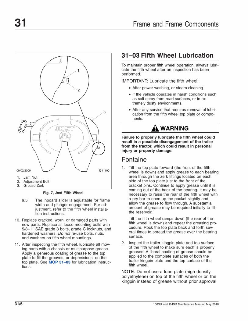
9.5 The inboard slider is adjustable for framewidth and plunger engagement. For ad-justment, refer to the fifth wheel installa-tion instructions.
10. Replace cracked, worn, or damaged parts withnew parts. Replace all loose mounting bolts with5/8–11 SAE grade 8 bolts, grade C locknuts, andhardened washers. Do not re-use bolts, nuts,and washers on fifth wheel mountings.
11. After inspecting the fifth wheel, lubricate all mov-ing parts with a chassis or multipurpose grease.Apply a generous coating of grease to the topplate to fill the grooves, or depressions, on thetop plate. See MOP 31–03 for lubrication instruc-tions.
31–03 Fifth Wheel LubricationTo maintain proper fifth wheel operation, always lubri-cate the fifth wheel after an inspection has beenperformed.
IMPORTANT: Lubricate the fifth wheel:
• After power washing, or steam cleaning.
• If the vehicle operates in harsh conditions suchas salt spray from road surfaces, or in ex-tremely dusty environments.
• After any service that requires removal of lubri-cation from the fifth wheel top plate or compo-nents.
WARNINGFailure to properly lubricate the fifth wheel couldresult in a possible disengagement of the trailerfrom the tractor, which could result in personalinjury or property damage.
Fontaine1. Tilt the top plate forward (the front of the fifth
wheel is down) and apply grease to each bearingarea through the zerk fittings located on eachside of the top plate just to the front of thebracket pins. Continue to apply grease until it iscoming out of the back of the bearing. It may benecessary to raise the rear of the fifth wheel witha pry bar to open up the pocket slightly andallow the grease to flow through. A substantialamount of grease may be required initially to fillthe reservoir.
Tilt the fifth wheel ramps down (the rear of thefifth wheel is down) and repeat the greasing pro-cedure. Rock the top plate back and forth sev-eral times to spread the grease over the bearingsurface.
2. Inspect the trailer kingpin plate and top surfaceof the fifth wheel to make sure each is properlygreased. A liberal coating of grease should beapplied to the complete surfaces of both thetrailer kingpin plate and the top surface of thefifth wheel.
NOTE: Do not use a lube plate (high densitypolyethylene) on top of the fifth wheel or on thekingpin instead of grease without prior approval
09/02/2009
3
1
2
f311100
1. Jam Nut2. Adjustment Bolt3. Grease Zerk
Fig. 7, Jost Fifth Wheel
Frame and Frame Components31
108SD and 114SD Maintenance Manual, May 201631/6

by Fontaine Fifth Wheel. The additional thick-ness of this material can prevent the proper op-eration of the fifth wheel and may cause a dan-gerous condition.
NOTE: Fontaine suggests the use of a Molybased lubricant such as Mobilgrease XHP 320or equivalent when applying lubricant to thelocking jaw and wedge.
3. Lubricate the fifth wheel prior to opening andclosing it. Separate the jaw and wedge with ascrewdriver, and grease the full length of theirmating surfaces. Lubricate the top and bottomcontact surfaces of the jaw and wedge. SeeFig. 5. Open and close the fifth wheel severaltimes to further distribute the grease.
Lightly oil other moving parts in the fifth wheel.
4. Apply grease to the top plate. Spread grease allover the mating surface of the top plate. Be surethe grease pockets built into the top plates arefull of grease.
Holland FWS1Apply a heavy coat of grease to the top plate, eitherthrough the grease fittings located on the undersideof the top plate, or by direct application.
Holland FW351. Using a water-resistant lithium-base grease,
grease the top plate.
2. Using a light oil (such as SAE 10W or 20Wmotor oil), lubricate the cam track and pivot. SeeFig. 8.
3. Grease the yoke tips, locks, and the releasehandle and spring; see Fig. 9. Grease themounting bracket supports through the greasefittings. A “low temp” grade grease rated for-30°F (-34°C) or lower such as Cato Oil andGrease #5213, Craftsman Chemical Co. #LTF 2,Mystic LP-200, or equivalent is recommended.
JostLubricate the kingpin lock using a hand pump greasegun through the grease zerk on the skirt of the fifthwheel; see Fig. 7. Apply a light oil to all movingparts. For sliding fifth wheels spray diesel fuel on theslide path of the base plate.
12/03/2010 f311136
1
Use a light oil (such as SAE 10W or 20W motor oil) tolubricate the cam track and pivot.
1. Cam Plate
Fig. 8, Holland FW35 Fifth Wheel, Oil Lubrication
12/03/2010 f311135
1
2
2
3 3
4
1. Release Handle andSpring
2. Grease Fitting
3. Yoke Tip4. Locks
Fig. 9, Holland FW35 Fifth Wheel, Grease Lubrication
Frame and Frame Components 31
108SD and 114SD Maintenance Manual, May 2016 31/7

NOTICEDo not use a power grease gun. The pressure willdamage the lube line.
If the fifth wheel is not equipped with low-lube plates,apply a lithium-based grease with extreme pressure(EP) additive to the trailer contact surface of the fifthwheel.
NOTE: If the fifth wheel is equipped with low-lubeplates, the top plate only requires lubrication at thenew product break-in stage. The low-lube plates re-quire no further lubrication.
31–04 Trailer ElectricalConnector Protection
In some cases, failure of trailer cables occurs due tointrusion of chloride-based road deicing chemicalsinto the trailer connector. Once inside the connector,the chloride-based chemicals corrode the brass ter-minals and create bridging between positive andground terminals.
NOTE: The use of soap is not recommended forcleaning the electrical connector, as somesoaps may increase the corrosion process.
1. Wash out any existing grease, dirt, and corrosionon the trailer connectors with electrical contactcleaner spray.
2. Grease the trailer connector with a lithium-baseddielectric grease.
Frame and Frame Components31
108SD and 114SD Maintenance Manual, May 201631/8

Title of Maintenance Operation (MOP) MOP Number
Safety Precautions. . . . . . . . . . . . . . . . . . . . . . . . . . . . . . . . . . . . . . . . . . . . . . . . . . . . . . . . . . . . . . . . . 32–00
Suspension Inspection . . . . . . . . . . . . . . . . . . . . . . . . . . . . . . . . . . . . . . . . . . . . . . . . . . . . . . . . . . . . . . 32–01
Suspension Lubrication. . . . . . . . . . . . . . . . . . . . . . . . . . . . . . . . . . . . . . . . . . . . . . . . . . . . . . . . . . . . . . 32–02
Suspension U-Bolt Torque Check . . . . . . . . . . . . . . . . . . . . . . . . . . . . . . . . . . . . . . . . . . . . . . . . . . . . . . 32–03
Suspension 32Index, Alphabetical
108SD and 114SD Maintenance Manual, September 2015

32–00 Safety PrecautionsSafety Precautions in this section apply to allprocedures within this group.
DANGERWhen working on the vehicle, shut down the en-gine, set the parking brake, and chock the tires.Before working under the vehicle, always placejack stands under the frame rails to ensure thevehicle cannot drop. Failure to follow these stepscould result in serious personal injury or death.
32–01 Suspension Inspection
Front Suspension Check
WARNINGDo not replace individual leaves of a damaged leafspring assembly; replace the complete spring as-sembly. Visible damage (cracks or breaks) to oneleaf causes hidden damage to other leaves. Re-placement of only the visibly damaged part(s) isno assurance that the spring is safe. On frontspring assemblies, if cracks or breaks exist in thetwo top leaves, a loss of vehicle control couldoccur. Failure to replace a damaged spring assem-bly could cause an accident resulting in propertydamage, serious personal injury, or death.
Inspect the front spring assemblies for cracked, bro-ken, or abnormally bent leaves. If any of these condi-tions exist, replace the spring assembly. See Group32 of the 108SD and 114SD Workshop Manual forinstructions.
Shock Absorber Check, Frontand Rear SuspensionsMake sure the shock absorber brackets are tight,and the shock absorber is not striking or rubbing theframe or some other part of the chassis. Striking orrubbing the frame is characterized by chafe marks onthe shock absorber body and the frame rail. Checkthe rubber mounting bushings for cracks, cuts, swell-ing, and dry rot. Also, check the bushings for missingpieces. Replace the bushings as needed.
Inspect the shock absorber for oil leakage. If theshock absorber is damaged or leaking, replace it witha new one. See Group 32 of the 108SD and 114SDWorkshop Manual for replacement instructions.
Rear Suspension CheckFreightliner Spring Suspension
WARNINGDo not replace individual leaves of a damaged leafspring assembly; replace the complete spring as-sembly. Visible damage (cracks or breaks) to oneleaf causes hidden damage to other leaves. Re-placement of only visibly damaged parts is no as-surance that the spring is safe. Failure to replacea damaged spring assembly could cause an acci-dent, resulting in serious personal injury or prop-erty damage.
Replace worn, cracked, or damaged springbrackets. Failure to do so could result in bracketbreakage, possibly leading to loss of vehicle con-trol and resulting in personal injury or propertydamage.
1. Inspect the forward and rear spring brackets andequalizer brackets for wear, cracks, and otherdamage. If any of these conditions exist, replacethe damaged bracket(s). See Group 32 of the108SD and 114SD Workshop Manual for instruc-tions.
2. Inspect the tandem-axle frame crossmember andgussets for wear, cracks, and other damage. Ifany of these conditions exist, replace the dam-aged parts. See Group 31 of the 108SD and114SD Workshop Manual for instructions.
NOTICEFailure to replace the suspension crossmember orgussets if they are cracked, worn, or otherwisedamaged could result in damage to the vehiclechassis.
3. Without detaching the torque arms, attempt tomove (by hand) each radius-rod end up, down,in, and out. If there is any movement, replace thetorque arm. If a torque arm needs to be re-placed, see Group 32 of the 108SD and 114SDWorkshop Manual for instructions.
Suspension 32
108SD and 114SD Maintenance Manual, September 2015 32/1

4. Inspect the weld seams between the torque armtube and the shorter bushing tubes. If there arecracks, replace the torque arm. Do not weld thetorque arm for any reason.
5. Inspect the rubber bushing ends. See Fig. 1. Re-place the torque arm for any of the following rea-sons:
• if there are gaps between the rubber bush-ing and the pin or outer steel sleeve;
• if either bushing end contacts a torque armpin mounting bolt;
• if there are cracks in the bushing;
• if part of the rubber bushing extends be-yond the outer circumference of the outerbushing sleeve.
6. Block up the frame enough to take chassisweight off the springs. Attempt to move theequalizer up and down, using a pry bar betweenthe top of the equalizer and top of the equalizerbracket; apply hand pressure only. See Fig. 2. Ifmovement at the center of the equalizer exceeds1/8 inch (3 mm), replace the equalizer bushings.See Group 32 of the 108SD and 114SD Work-shop Manual for instructions.
7. With the vehicle unloaded, attempt to move theequalizer side to side, using a pry bar betweenthe equalizer and frame rail. Apply hand pressureonly. See Fig. 3. If clearance between the equal-izer assembly and any frame component or fas-tener is less than 1/8 inch (3 mm), replace theequalizer bushings. See Group 32 of the 108SDand 114SD Workshop Manual for instructions.
Freightliner AirLiner Suspension
WARNINGDo not replace individual leaves of a damaged leafspring assembly; replace the complete spring as-sembly. Visible damage (cracks or breaks) to oneleaf causes hidden damage to other leaves. Re-placement of only the visibly damaged part(s) isno assurance that the spring is safe. On frontspring assemblies, if cracks or breaks exist in the
f320021a05/27/93
Fig. 1, Torque Arm Bushings
f320022a05/27/93
1
2
3
A
A. Measure the change in gap at this point.1. Equalizer Bracket2. Equalizer
3. Pry Bar
Fig. 2, Side View of the Equalizer
f320023a05/27/93
1 2
3
4
5
A
A. 1/8" (3 mm) Clearance1. Frame Fasteners2. Frame Rail3. Pry Bar
4. Equalizer5. Equalizer Bracket
Fig. 3, Top View of the Equalizer
Suspension32
108SD and 114SD Maintenance Manual, September 201532/2

two top leaves, a loss of vehicle control couldoccur. Failure to replace a damaged spring assem-bly could cause an accident resulting in propertydamage, serious personal injury, or death.
1. Inspect the forward and rear spring brackets forwear, cracks, and other damage. If any of theseconditions exist, replace the damaged bracket(s).See Group 32 of the 108SD and 114SD Work-shop Manual for instructions.
WARNINGReplace worn, cracked, or damaged springbrackets. Failure to do so could result in bracketbreakage, possibly leading to loss of vehicle con-trol and resulting in personal injury or propertydamage.
2. Inspect the crossmember(s) and gussets forwear, cracks, and other damage. If any of theseconditions exist, replace the damaged parts. SeeGroup 31 of the 108SD and 114SD WorkshopManual for instructions.
3. Visually check the air spring piston for cracks,chips, and broken areas. Check the air bag forrips, tears, and holes. Verify that the air springassembly does not leak. If any of these condi-tions exist, replace the damaged parts. SeeGroup 32 of the 108SD and 114SD WorkshopManual for instructions.
Freightliner AirLiner ComponentInspection and Operation Check
WARNINGInspect the components and check their operationas described below. Failure to perform these in-spections and checks could result in separation ofworn suspension components and loss of vehiclecontrol, possibly causing personal injury or death,or property damage.
1. Chock the front tires. Raise the rear of the ve-hicle so the tires just clear the ground and thesuspension is fully extended. Place safety standsunder the vehicle frame.
2. Squeeze all air springs to check for completedeflation.
3. Inspect the air spring piston for cracks, chips,and broken areas. Check the air bag for rips,
tears, and holes. Verify that the air spring assem-bly does not leak.
4. Check the axle connection welds (beam seat toequalizing beam) and axle adapter to axle forcracks. If welds are cracked, grind them out andreweld the parts observing the welding precau-tions given in Group 31 of the 108SD and114SD Workshop Manual.
5. Move the axle up and down while checking forsigns of looseness due to worn parts at the frontpivot connections. Replace any worn parts.
6. Inspect the shock absorbers for oil leaks andworn rubber bushings. Replace the shock ab-sorbers and/or rubber bushings if wear or dam-age is noted.
7. Inspect the stabilizer bar, if so equipped, for ir-regular bushing wear or cracks in the brackets.The stabilizer bar is optional on 10,000- and15,000-pound AirLiner suspension systems.
8. Remove the safety stands and lower the rear ofthe vehicle to the ground. Run the engine untilair pressure of at least 100 psi (689 kPa) ismaintained throughout the system.
9. Check that all air springs are inflated.
Freightliner AirLiner Control RodCheckNOTE: The Freightliner AirLiner Suspension ismanufactured at numerous weight ratings. Thecontrol rod on the 46,000-pound-rated suspen-sion is larger, and is fastened differently than onother applications.
1. Without disconnecting the control rods, use yourhand to attempt to move each of the control rodends up, down, in, and out. If there is any move-ment, examine the control rods for wear or dam-age. Replace if necessary.
2. Inspect the rubber bushings for cracks or cuts.
3. Check for any shifting of the barpin.
4. Check for cracks in the metal components andwelds.
Ride Height Valve CheckIMPORTANT: Before checking the AirLiner sus-pension height, make sure there is no load onthe chassis, and the trailer is unhitched.
Suspension 32
108SD and 114SD Maintenance Manual, September 2015 32/3

NOTICETo prevent voiding the warranty on Barksdaleheight-control valves, observe the following:
• When removing or loosening a Barksdaleheight-control valve from a mounting bracket,always hold the valve-side mounting studs inplace with an Allen wrench while loosening ortightening the nuts that attach the valve to thebracket. Because the mounting studs arethreaded into the valve body, loosening the nutswithout holding the studs can tighten the studs,which can crush the valve body and damagethe valve. Conversely, tightening the nuts with-out holding the studs can back the studs out,causing a separation of the two halves of thevalve body, and possibly a leak.
• Do not overtighten the bolts in the Barksdaleheight-control valve housing. The bolts shouldnot be loose, and should not require tightening.Only if necessary, tighten the valve housingbolts 45 lbf·in (500 N·cm). Any damage to thevalve housing will void the warranty.
• Do not attempt to disassemble the Barksdalevalve body or the control lever. There are noserviceable parts in the valve, and any disas-sembly will void the warranty.
1. Park the vehicle on a level surface, using a lightapplication of the brakes. Do not apply the park-ing brakes. Shift the transmission into neutral,and build the secondary air pressure to at least100 psi (690 kPa). Shut down the engine.
2. Mark the location of the front and rear tires onthe floor, and chock the tires on one axle only.
3. Check that the height-control valve vertical link-age is connected and oriented correctly.
NOTE: The stud bolt that fastens the height-control valve horizontal lever to the vertical link-age is oriented correctly when the linkage rod isvertical, as viewed from the side of the vehicle;see Fig. 4. The rod may be on the forward oraft side of the lever to get it to be vertical.
4. Measure the distance from the axle stop to thetop of the axle U-bolt pad. The correct distanceis determined by the axle and suspension con-figurations; refer to Group 32 of the 108SD and114SD Workshop Manual for details.
5. If the axle stop measurement is not correct, seeGroup 32 of the 108SD and 114SD WorkshopManual for adjustment procedures.
6. Apply the parking brakes, and remove thechocks.
Freightliner TufTrac1. Inspect the suspension spring assemblies for
pitted, cracked, broken, or abnormally bentleaves, and extreme rust. If any of these condi-tions exist, replace the spring assembly.
WARNINGDo not replace individual leaves of a damaged leafspring assembly; replace the complete spring as-sembly. Visible damage (cracks or breaks) to oneleaf causes hidden damage to other leaves. Re-placement of only the visibly damaged part(s) isno assurance that the spring is safe. On front
f320562a10/05/2016
1 2
3
4
5
1. Valve MountingBracket
2. Height-Control Valve
3. Stud Bolt4. Linkage Rod5. Axle
Fig. 4, Typical Barksdale Height-Control ValveInstallation (side view)
Suspension32
108SD and 114SD Maintenance Manual, September 201532/4

spring assemblies, if cracks or breaks exist in thetwo top leaves, a loss of vehicle control couldoccur. Failure to replace a damaged spring assem-bly could cause an accident resulting in propertydamage, serious personal injury, or death.
IMPORTANT: On multi-leaf suspensions, closelyinspect each component of the leaf spring as-semblies, including the brackets, U-bolts, andrelated parts.
2. Inspect the brackets for cracks in the castings.Inspect the V-rod tower welds for cracking orother signs of damage. Also check for contactbetween the frame rail and the upper axle clampbrackets. If contact exists, check the V-rod bush-ing for wear. Check the V-rod fastener torques.
3. Inspect the rubber center bearing and spring tippads for excessive wear, including de-laminationof the rubber-to-metal shim interface, and distor-tion and degradation of rubber.
4. Inspect the V-rods and lower control rods forwear and looseness.
4.1 Without disconnecting the control rods,use your hand to attempt to move each ofthe control rod ends up, down, in, andout. If there is any movement, examinethe control rods for wear or damage. Re-place if necessary.
4.2 Inspect the rubber bushings for cracks orcuts.
4.3 Check for any shifting of the barpin.
4.4 Check for cracks in the metal compo-nents and welds.
5. Check all fasteners for looseness.
6. Inspect the shock absorbers for oil leaks andworn rubber bushings. Replace the shock ab-sorbers and/or rubber bushings if wear or dam-age is noted.
Chalmers Suspension1. Chock the front tires, place the transmission in
neutral, and release the parking brakes.
2. Power wash the suspension, or clean it with ahard-bristle brush before performing a visual in-spection.
3. Inspect the rubber bushings for cracks or otherdamage.
Try to move the torque rod ends using yourhands only, and check for any free-play. If free-play is felt, replace the torque rod end bushing.Do not use a pry bar to check for free-play. Useof a pry bar may lead to premature bushing re-placement.
4. Lift the rear of the vehicle and support the frameon jack stands to unload the suspension compo-nents. The vehicle is lifted high enough when thebeam ends are off of the saddles.
Inspect the walking beam for cracks or otherdamage. If damage is found, replace the walkingbeam.
Keep the vehicle supported by the jack standsfor the next operation.
5. Manipulate the walking beam so that a microm-eter, vernier, or dial caliper can be used to deter-mine the wear area thickness on the bottomface. See Fig. 5. Measurements should be takena minimum of 1/2 inch from the beam flangeedges to eliminate any edge wear that may haveoccurred. Subtract the wear area thickness (seeFig. 5, Ref. B) from the thickness at the non-wear area (see Fig. 5, Ref. A) to determine theamount of wear.
If the beams show any wear greater than 0.062inch (1.5 mm), a Chalmers wear plate must beinstalled, or the walking beam must be replaced.
6. Rotate the restrictor cans 360 degrees and in-spect the cans for cracks, severe corrosion, anddistortion. If any of these conditions are present,or the restrictor can is missing, replace the re-strictor can.
WARNINGReplace all cracked or missing restrictor cans.Failure to do so could lead to loss of vehicle con-trol, which could result in property damage, seri-ous personal injury, or death.
32–02 Suspension Lubrication
Freightliner Spring FrontSuspensionWipe all dirt from the grease fittings at the forwardspring pin and the spring shackle pins. Then apply
Suspension 32
108SD and 114SD Maintenance Manual, September 2015 32/5

multipurpose chassis grease with a pressure gununtil the old grease is forced out.
Freightliner Spring RearSuspensionSingle AxleLubrication is not required on single-axle spring rearsuspensions.
Tandem Axle
NOTICEIf the equalizer cap and tube assembly isequipped with a nonrelief grease fitting, excessivelubrication can damage the bushings.
Lubricate the equalizer cap and tube assembly bush-ings by applying multipurpose chassis grease at thepressure relief grease fitting. See Fig. 6. Lubricatewith a hand gun or pressure gun until grease isforced out from the base of the pressure-relief fitting.
HendricksonThe Hendrickson RS Series Haulmaax®, HN®, andPrimaax® suspensions do not require lubrication.
For Hendrickson RT® and RTE® series suspensions,lubricate the bronze, ball-indented bushings in thespring eye, as follows:
1. Park the vehicle on a level surface, apply theparking brakes, and chock the front tires.
2. Raise the rear of the vehicle until the rear wheelsare suspended in the air, then support the ve-hicle with safety stands. This relieves the load onthe bushings and pins to allow the proper flow oflubricant around them.
3. Using a multipurpose chassis grease, lubricatethe bronze, ball-indented bushings in the springeyes at the grease fitting; see Fig. 7. Continue tolubricate until grease exits both ends of thebushing. If the pin will not accept lubricant, re-move the pin and clean the lubrication channelswhere lubricant may have hardened.
4. Lower the vehicle and remove the safety stands.
32–03 Suspension U-BoltTorque Check
Check the U-bolt torque of both the front and rearaxles where applicable.
09/27/95 f320432
1
A
B
A. Non-Wear Area B. Wear Area1. Walking Beam
Fig. 5, Walking Beam End Wear Thickness
320020a05/27/93
1
1
A
A. Lubricate here.1. Cap and Tube Assembly Bushing
Fig. 6, Equalizer Assembly Lubrication
Suspension32
108SD and 114SD Maintenance Manual, September 201532/6

NOTICEFailure to tighten the U-bolt nuts to the specifiedtorque value could result in spring breakage andabnormal tire wear.
1. Park the vehicle on a flat surface and apply theparking brakes. Chock the tires to prevent thevehicle from moving.
2. Check the U-bolt torque in a diagonal pattern.Set a click-type torque wrench to the highesttorque value for the fastener being checked. SeeFig. 8 for the tightening pattern. See Table 1 forU-bolt torque specifications. Turn the wrench in aclockwise motion (looking up) until the torquewrench clicks.
Spring Assembly U-Bolt High Nut Torque Values*
Size Torque: lbf·ft (N·m)
5/8–18
Stage 1: Hand-tightenStage 2: 60 (81)Stage 3: 200 (271)Stage 4: 180 to 230 (245 to 313)
3/4–16
Stage 1: Hand-tightenStage 2: 60 (81)Stage 3: 200 (271)Stage 4: 270 to 330 (367 to 449)
7/8–14
Stage 1: Hand-tightenStage 2: 60 (81)Stage 3: 200 (271)Stage 4: 420 to 500 (571 to 680)
1–14
Stage 1: Hand-tightenStage 2: 60 (81)Stage 3: 200 (271)Stage 4: 520 to 600 (707 to 816)
* Tighten in a diagonal pattern as shown in Fig. 8.
Table 1, Spring Assembly U-Bolt High Nut TorqueValues
09/15/95 f320424
1
2
2 3
4
4
1. Bronze Bushing2. Lubrication Hole
3. Grease Fitting4. Lubrication Groove
Fig. 7, Hendrickson RT2 and RTE2 Series BushingLubrication
f32078310/05/2016
1
2 3
4
Fig. 8, Tightening Pattern for U-Bolt High Nuts
Suspension 32
108SD and 114SD Maintenance Manual, September 2015 32/7

Title of Maintenance Operation (MOP) MOP Number
Alignment Check . . . . . . . . . . . . . . . . . . . . . . . . . . . . . . . . . . . . . . . . . . . . . . . . . . . . . . . . . . . . . . . . . . 33–04
Knuckle Pin Lubrication . . . . . . . . . . . . . . . . . . . . . . . . . . . . . . . . . . . . . . . . . . . . . . . . . . . . . . . . . . . . . 33–01
Safety Precautions. . . . . . . . . . . . . . . . . . . . . . . . . . . . . . . . . . . . . . . . . . . . . . . . . . . . . . . . . . . . . . . . . 33–00
Steer Axle Hub Cap Vent Plug Inspection . . . . . . . . . . . . . . . . . . . . . . . . . . . . . . . . . . . . . . . . . . . . . . . . 33–06
Tie Rod Inspection . . . . . . . . . . . . . . . . . . . . . . . . . . . . . . . . . . . . . . . . . . . . . . . . . . . . . . . . . . . . . . . . . 33–02
Tie Rod Lubrication . . . . . . . . . . . . . . . . . . . . . . . . . . . . . . . . . . . . . . . . . . . . . . . . . . . . . . . . . . . . . . . . 33–03
Wheel End Inspection, Front Axle . . . . . . . . . . . . . . . . . . . . . . . . . . . . . . . . . . . . . . . . . . . . . . . . . . . . . . 33–05
Front Axle 33Index, Alphabetical
108SD and 114SD Maintenance Manual, November 2016

33–00 Safety PrecautionsSafety Precautions in this section apply to allprocedures within this group.
DANGERWhen working on the vehicle, shut down the en-gine, set the parking brake, and chock the tires.Before working under the vehicle, always placejack stands under the frame rails to ensure thevehicle cannot drop. Failure to follow these stepscould result in serious personal injury or death.
33–01 Knuckle Pin Lubrication
NOTICEUse regulated pressure when lubricating theknuckle assemblies, otherwise damage could re-sult to the knuckle caps.
Detroit™ Axles1. Park the vehicle on a level surface, shut down
the engine, and set the parking brake. Chock thetires. When lubricating upper and lower knuckleassemblies, do not raise the front axle.
2. Wipe the fittings clean.
3. Apply multipurpose chassis grease, NLGI Grade1 (6% 12-hydroxy lithium stearate grease) orNLGI Grade 2 (8% 12-hydroxy lithium stearategrease), until new grease is seen at the junctionsof the axle beam and knuckles. For locations ofgrease fittings, see Fig. 1; for grease exit points,see Fig. 2.
Dana Spicer AxlesPark the vehicle on a level surface, apply the parkingbrakes, and chock the tires. When lubricating upperand lower knuckle assemblies, do not raise the frontaxle. Wipe the fittings clean, then apply multipurposechassis grease, NLGI Grade 1 (6% 12-hydroxylithium stearate grease) or NLGI Grade 2 (8% 12-hydroxy lithium stearate grease), until new grease isseen at the junctions of the axle beam and knuckles.See Fig. 3. Knuckle pins without grease fittings arepermanently lubricated.
Meritor AxlesPark the vehicle on a level surface, apply the parkingbrakes, and chock the tires. When lubricating knucklepin bushings, do not raise the front axle. Wipe thelube fittings clean, and apply multipurpose chassis
06/07/2012 f330272
A
B
1
1
A Upper View, LH Side B Lower View, LH Side1. Grease Fitting
Fig. 1, Grease Fittings, Detroit Axles
09/13/2012 f330275
Fig. 2, Knuckle Pin Grease Exit Points, Detroit Axles
Front Axle 33
108SD and 114SD Maintenance Manual, November 2016 33/1

grease, NLGI Grade 2 (8% 12-hydroxy lithium stear-ate grease), until new grease is seen at the bushinggrease seal opposite the fittings. The grease seal willaccept grease pressure without damage, and is de-signed to have grease pumped out through it duringlubrication. Even if grease leaks out around the top,or bottom-plate gasket, continue pumping until newgrease is seen at the bushing seal opposite thegrease fitting; see Fig. 4.
NOTE: For operation in very cold climates, useNLGI Grade 1 (6% 12-hydroxy lithium stearategrease).
33–02 Tie Rod InspectionIMPORTANT: If the tie rod end boot is torn ormissing, replace the entire tie rod end. Do notreplace the boot only.
1. Shut off the engine, apply the brakes, and chockthe rear tires.
2. Check the tie rod boot for cracks, tears, or otherdamage. If the tie rod boot is damaged, replacethe entire tie rod end.
3. Grasp by hand (or use a pipe wrench with jawprotectors to avoid gouging the cross tube) andslightly rotate the cross tube toward the front ofthe vehicle and then slightly toward the rear.Then center the cross tube between the stop po-sitions. If the cross tube does not rotate in eitherdirection, replace both tie rod ends.
4. Position yourself directly below the ball studsocket. Using both hands, grab the end as closeto the socket as possible, no more than 6 inches(15.2 cm) from the end. Firmly apply about 100pounds of hand pressure in an up and down mo-tion several times. When moving the assembly,check for any movement at both tie rod ends.See Fig. 5.
If any movement is detected at one tie rod end,replace both tie rod ends. Always replace tie rodends in pairs, even if only one tie rod end isdamaged.
11/21/95 f330129
1
1
A
A. Grease exits1. Grease Fitting
Fig. 3, Dana Spicer Knuckle Pin Lubrication09/06/96 f320032a
A
1
1
A. Grease Exits1. Grease Fitting
Fig. 4, Knuckle Pin Lubrication, Meritor Axles
10/10/2001 f330195
Fig. 5, Check Movement of Tie Rod End
Front Axle33
108SD and 114SD Maintenance Manual, November 201633/2

NOTICEDo not attempt to straighten a bent cross tube.Doing so could result in damage to the axle. Besure to replace the cross tube with an originalequipment cross tube with the same length, diam-eter, and thread size as the existing cross tube.
5. Check the cross tube for cracks or other dam-age. If the cross tube is bent or damaged, re-place the cross tube.
6. Check the clamps for damage. If a clamp isdamaged, replace the clamp. Replace the entirecross tube assembly if either clamp is welded tothe cross tube.
7. Check for proper installation of the tie rod endclamp to the cross tube. Make sure that the tierod ends are threaded in the cross tube past theclamps and the slots at the cross tube ends.
8. Check the zerk fittings for damage. If a zerk fit-ting is damaged, replace it.
Some tie rod ends have no zerk fittings becausethey are not greaseable. Do not install a zerkfitting on a nongreaseable tie rod end.
9. Check that the cotter pin is in place. If it is not,tighten the tie rod end nut to one of the followingspecs depending on the axle manufacturer.
For Detroit axles, tighten the castle nut to 120 to170 lbf·ft (163 to 230 N·m). To align the cotterpin hole with the castle nut slot, turn the nut upto 1/6 turn (maximum).
For Meritor axles, tighten the tie rod end nut perthe size of the stud:
• 7/8–14, 160 to 300 lbf·ft (217 to 406 N·m)
• 1–14, 250 to 450 lbf·ft (339 to 610 N·m)
• 1-1/8–12, 350 to 650 lbf·ft (475 to 881N·m)
• 1-1/4–12, 500 to 675 lbf·ft (678 to 915N·m)
10. Check the steering arm bolts for a minimumtorque of 300 lbf·ft (406 N·m). If the steering armbolt torque has fallen below this specification,remove the bolt, clean all the threads, and applynew Loctite® 680. Tighten the bolt 300 to 450lbf·ft (406 to 610 N·m).
11. Remove the chocks from the tires.
33–03 Tie Rod Lubrication
Detroit and Meritor AxlesFor any Detroit or Meritor axle that requires lubrica-tion of the tie-rod ends, wipe the grease fittingsclean, then pump multipurpose chassis grease, NLGIGrade 1 (6% 12-hydroxy lithium stearate grease) orNLGI Grade 2 (8% 12-hydroxy lithium stearategrease), into the tie-rod ends until all used grease isforced out and fresh grease is seen at the ball studneck. See Fig. 6.
Dana Spicer AxlesFor any Dana Spicer axle that requires lubrication ofthe tie-rod ends, wipe the grease fittings clean, thenpump multipurpose chassis grease, NLGI Grade 2(8% 12-hydroxy lithium stearate grease), into the tie-rod ends until all used grease is forced out and freshgrease is seen at the ball stud neck.
NOTE: For operation in very cold climates, useNLGI Grade 1 (6% 12-hydroxy lithium stearategrease).
33–04 Alignment Check
Drive Axle Alignment CheckingCheck the axle alignment, parallelism, and thrustangle measurements for the rear drive axles. For
06/12/2012 f3302731
2
NOTE: No grease should emit from the tie-rod boot. Ifgrease emits from the tie-rod boot, the boot is dam-aged.
1. Grease Fitting 2. Boot
Fig. 6, Grease Fitting and Boot (Detroit axle shown)
Front Axle 33
108SD and 114SD Maintenance Manual, November 2016 33/3

specifications and procedures, see Group 35 of the108SD and 114SD Workshop Manual.
Toe-In InspectionFor vehicle alignment to be accurate, the shop floormust be level in every direction. The turn plates forthe front wheels must rotate freely without friction,and the alignment equipment must be calibratedevery three months by a qualified technician from theequipment manufacturer. Freightliner dealers musthave proof of this calibration history.
1. Apply the parking brakes and chock the reartires.
2. Raise the front of the vehicle until the tires clearthe ground. Place safety stands under the axle.
3. Using spray paint or a piece of chalk, mark theentire center rib of each front tire.
4. Place a scribe or pointed instrument against themarked center rib of each tire, and turn the tires.The scribe must be held firmly in place so that asingle straight line is scribed all the way aroundeach front tire.
5. Place a turn-plate or turntable under both fronttires. Remove the safety stands and lower thevehicle. Remove the lock-pins from the gauges;make sure the tires are exactly straight ahead.
NOTE: If turn-plates or turntables are not avail-able, lower the vehicle. Remove the chocksfrom the rear tires and release the parkingbrakes. Move the vehicle backward, then for-ward about six feet (two meters).
6. Place a trammel bar at the rear of the front tires;locate the trammel pointers at spindle height,and adjust the pointers to line up with the scribelines on the center ribs of the front tires. SeeFig. 7. Lock in place. Check that the scale is seton zero.
7. Place the trammel bar at the front of the tires(see Fig. 8) and adjust the scale end so that thepointers line up with the scribe lines. See Fig. 9.
8. Read the toe-in from the scale, and compare it tothe toe-in specification in Group 33 of the108SD and 114SD Workshop Manual. If correc-tions are needed, refer to Group 33 of the108SD and 114SD Workshop Manual for instruc-tions on adjusting the toe-in.
33–05 Wheel End Inspection,Front Axle
1. Park the vehicle on a level surface, shut downthe engine, set the parking brake, and chock thetires.
WARNINGNever work around or under a vehicle that is sup-ported only by a jack. Always support the vehiclewith safety stands. Jacks can slip, causing thevehicle to fall, which could result in serious injuryor death.
2. Raise the front of the vehicle and support it withsafety stands.
f330082a10/05/2016
A
B
NOTE: B minus A equals toe-in.
Fig. 7, Wheel Toe-In (overhead view)
f330014a10/05/2016
Fig. 8, Trammel Bar Positioning
Front Axle33
108SD and 114SD Maintenance Manual, November 201633/4

3. Remove the front wheel and tire assemblies. Forinstructions, see Group 40 of the 108SD and114SD Workshop Manual.
4. Remove the brake drum. For more information,see Group 33 of the 108SD and 114SD Work-shop Manual.
5. Check for loose, damaged, or missing fastenersand hubcaps.
6. Check for lubricant around the hub cap andwheel. If lubricant is present, investigate thecause and take corrective action.
7. Check for lubricant around the hub, brake hard-ware, and brake shoes (if installed). If lubricant ispresent, check the oil seal and replace it as nec-essary. For instructions, see Section 33.02 ofthe 108SD and 114SD Workshop Manual.
8. Inspect the lubricant for discoloration. Under nor-mal conditions, the lubricant will darken; a whiteor milky appearance indicates water contamina-tion. If the lubricant is discolored, service thewheel end. See the 108SD and 114SD Work-shop Manual and manufacturer literature for pro-cedures.
IMPORTANT: Do not mix different types of lubri-cants.
9. Inspect the lubricant for the presence of foreignmatter. Use a magnet to detect any metallic ma-terials present in the lubricant. If the lubricant iscontaminated, service the hub. See the 108SDand 114SD Workshop Manual and manufacturerliterature for procedures.
10. Rotate the hub and check for free, smooth, andquiet rotation. If rotation is hampered, service thehub immediately. See the 108SD and 114SDWorkshop Manual and manufacturer literature forprocedures.
WARNINGCorrect wheel-bearing end play is crucial to thesafe and sound operation of the vehicle. If the endplay is not correct, the wheel bearings could failand cause the loss of the wheel and hub assem-bly and result in an accident causing propertydamage, serious injury, or death. Use a dial indica-tor to measure the end play.
IMPORTANT: Do not measure the wheel bear-ing end play with the wheel mounted on thehub; you cannot accurately measure or adjustbearing end play with the wheel mounted on thehub. Also, ensure that the brakes are not ap-plied so that that drum and hub can move freely.
11. Using a dial indicator, measure the end play asfollows.
11.1 Attach the magnetic base of a dial indica-tor to the end of the spindle, and placethe measuring end of the indicatoragainst the hub cap mounting flange. SeeFig. 10.
IMPORTANT: Maintain continual pressure onthe hub until you have taken both the in-board and outboard measurements. If yourelease the hub, an accurate measurementis not possible.
11.2 To seat the bearings, grip the hub at thethree o’clock and nine o’clock positions,and push inward while oscillating it ap-proximately 45 degrees. Maintain pres-sure on the hub, note the inboard mea-surement, and then pull the hub outwardwhile oscillating it as before. Maintain
f400100a10/05/2016
Fig. 9, Setting Trammel Bar Pointers
Front Axle 33
108SD and 114SD Maintenance Manual, November 2016 33/5

pressure on the hub, and note the out-board measurement. See Fig. 11.
The end play is the difference betweenthe two measurements. The end play limitfor PreSet hubs is 0.006 inch (0.15 mm);for non-PreSet hubs the acceptable rangeis 0.001 to 0.005 inch (0.03 to 0.13 mm)inclusive.
If the end play does not exceed the limitand no other problems were found in theprevious steps, no additional service isnecessary. If the end play exceeds thelimit, service the hub. See the 108SD and114SD Workshop Manual and manufac-turer literature for procedures.
33–06 Steer Axle Hub Cap VentPlug Inspection
General InformationAs a function of their design, hubcap vent plugs willon occasion exhibit signs of hub oil on their exteriorsurface. Depending on environmental conditionsand/or age of the plug, the amount of oil present canvary. This is a normal result of the venting process
due to pressure increase within the hub cavity. Foran example of normal vent plug appearance, seeFig. 12.
A vent plug can wear or be damaged and cause ex-cessive leakage, or allow water to enter the hub andcontaminate the oil. For examples of a leaking ventplug, see Fig. 13 and Fig. 14. Evidence of a leakingvent plug may appear as;
06/20/2011 f330270
1
2
1. Hub Cap Mounting Flange2. Dial Indicator (with magnetic base)
Fig. 10, Dial Indicator Setup
06/21/2011 f330271
A
A
A. Pull and push the hub while oscillating it.
Fig. 11, Measuring End Play
f33029809/01/2016
Fig. 12, Normal Oil Venting
Front Axle33
108SD and 114SD Maintenance Manual, November 201633/6

• Oil splatter around the wheel
• Gooey/gummy oil around the vent plug purgepoint
• Hub/plug area is dirty, and water contaminatedoil in the hub.
• Hub/plug area is clean, but there is water con-taminated oil in the hub. (pressure washing isthe most likely cause)
Inspection
NOTICEOnly remove vent plugs by hand. They can bedamaged if a tool is used. Wipe the hub/plug areaclean before checking the oil. Do not use a pres-sure washer to clean the hub/plug area. The plughas a vent and this can contaminate the oil withwater.
1. Park the vehicle on a level surface, shut downthe engine and set the parking brakes. Chockthe tires.
2. Inspect the axle hub cap and vent plug for evi-dence of excessive leakage.
3. Wipe the hub cap and vent plug clean with a rag.
4. Remove the vent plug and check the oil for evi-dence of water contamination.
If there is evidence of water contaminated oil inthe hub, disassemble the effected axle end,clean, inspect, and reassemble the axle end. Forinstructions, refer to Group 33 of the vehicle’sWorkshop Manual.
If there is evidence of excessive leakage, re-move the damaged part and replace it with anew part.
5. Check the oil level in the hub, and fill the hubwith new approved oil as needed.
f33029909/01/2016
Fig. 13, Excessive Leakage
f33030009/01/2016
Fig. 14, Water in Oil
Front Axle 33
108SD and 114SD Maintenance Manual, November 2016 33/7

Title of Maintenance Operation (MOP) MOP Number
Axle Breather Check . . . . . . . . . . . . . . . . . . . . . . . . . . . . . . . . . . . . . . . . . . . . . . . . . . . . . . . . . . . . . . . 35–02
Axle Lubricant Level Check . . . . . . . . . . . . . . . . . . . . . . . . . . . . . . . . . . . . . . . . . . . . . . . . . . . . . . . . . . 35–01
Axle Lubricant and Filter Change, and Magnetic Strainer Cleaning and Check . . . . . . . . . . . . . . . . . . . . . 35–03
Safety Precautions. . . . . . . . . . . . . . . . . . . . . . . . . . . . . . . . . . . . . . . . . . . . . . . . . . . . . . . . . . . . . . . . . 35–00
Wheel End Inspection, Rear Axle . . . . . . . . . . . . . . . . . . . . . . . . . . . . . . . . . . . . . . . . . . . . . . . . . . . . . . 35–04
Rear Axle 35Index, Alphabetical
108SD and 114SD Maintenance Manual, November 2016

35–00 Safety PrecautionsSafety Precautions in this section apply to allprocedures within this group.
DANGERWhen working on the vehicle, shut down the en-gine, set the parking brake, and chock the tires.Before working under the vehicle, always placejack stands under the frame rails to ensure thevehicle cannot drop. Failure to follow these stepscould result in serious personal injury or death.
35–01 Axle Lubricant LevelCheck
NOTICEFailure to keep the rear axle filled to the properlevel with the recommended lubricant can result inrear axle damage.
1. Park the vehicle on a level surface, shut downthe engine, and set the parking brake. Chock thetires.
2. If the vehicle has just been driven, allow a fewminutes for the lubricant to settle.
NOTE: Some Detroit and Meritor axles have asmall tapped and plugged hole located belowthe housing oil fill hole. This smaller hole is forthe lubricant temperature sensor only and mustnot be used as a fill or level hole.
3. Clean the oil fill hole plug (located in the carrieror the side of the axle housing) and the area sur-rounding it, then remove the plug.
For Detroit axles, see Fig. 1; for Meritor axles,see Fig. 2; for Dana Spicer axles, see Fig. 3.
IMPORTANT: A lubricant level close enough tobe seen or touched is not sufficient. It must belevel with the bottom of the fill hole.
4. Check the level of the lubricant. The lubricantmust be level with the bottom of the oil fill hole.See Fig. 4. If low, add lubricant.
For Detroit axles, see Table 1 for approved axlelubricants and Table 2 for lubricant capacities.
For Meritor axles, see Table 3 for approved axlelubricants, and Table 4 or Table 5 for axle ca-pacities.
For Dana Spicer axles, see Table 6 for approvedaxle lubricants, and Table 7 for axle capacities.
1
2
4 3
2
B
A
12/07/2010 f350509a
A. Front ViewB. Rear View1. Axle Breather2. Breather Hose3. Temperature Sensor Port4. Oil Fill Plug
Fig. 1, Detroit Tandem Axle (forward axle shown)
Rear Axle 35
108SD and 114SD Maintenance Manual, November 2016 35/1

5. Install the oil fill hole plug and tighten it per thefollowing:
• For Detroit axles: 30 lbf·ft (41 N·m).
• For Meritor axles: 35 lbf·ft (47 N·m).
• For Dana Spicer axles: 50 lbf·ft (68 N·m).
6. On non-drive axles using oil-lubricated wheelbearings, clean the hub cap and plug to minimizethe possibility of dirt and road grime entering theassembly. Remove the plug, and check the oillevel. If low, add fluid using the same lubricantrecommended for the drive axle.
f350062a10/05/2016
1
2 3
1. Axle Housing Breathers2. Carrier Oil Fill Plugs3. Interaxle Differential
Fig. 2, Fill Hole Plug and Axle Housing BreatherLocations, Meritor Axles
12/09/2010 f350531
1
2
3
1. Oil Fill Plug2. Oil Drain Plug3. Axle Breather
Fig. 3, Oil Fill and Drain Plugs and Axle Breather, DanaSpicer Axles
f350061a10/05/2016
A
B
A. Correct (lube level at bottom of fill hole)B. Incorrect (lube level below fill hole)
Fig. 4, Axle Lubricant Level Check
Rear Axle35
108SD and 114SD Maintenance Manual, November 201635/2

Detroit Drive Axle Lubricants*
IMPORTANT: Lubricant used in Detroit rear axles mustmeet Mercedes-Benz specification 235.20 (mineral) or
235.8 (synthetic). Mobil Delvac™ Gear Oil A 80W-90 andMobilube™ HD-A Plus 80W-90 meet specification 235.20.
Mobil Delvac 1 Gear Oil 75W-90 and Mobilube 1 SHC75W-90 meet specification 235.8. For more product
information, see http://bevo.mercedes-benz.com.
Type Ambient TemperatureSAE
ViscosityGrade
Mineral Oil –15°F (–26.1°C) and up† 80W–90
Synthetic Oil –40°F (–40°C) and up† 75W–90* Detroit rear axles do not require the use of friction modifiers.† There is no upper limit on the ambient temperature, but axle sump tem-
perature must never exceed 250°F (121°C).
Table 1, Detroit Drive Axle Lubricants
Detroit Rear Axle Lubricant Capacity (Hubs Full)
Axle Oil Capacity:Quarts (liters)
Forward-Rear, Model 4 14.3 (13.5)*
Single and Rearmost Tandem,Model 4 10.6 (10.0)*
Single, Model 2 5.8 (5.5)*
* These values assume the wheel ends are properly lubricated. Actual oilcapacity might vary slightly depending on gear ratio.
Table 2, Detroit Rear Axle Lubricant Capacity
35–02 Axle Breather CheckThe axle housing breather must remain clean. Whenthe axle lubricant level is checked, check that theaxle breather is open. Check more often under ad-verse operating conditions. If the breather is plugged,clean it or replace it as needed.
For the location of the breather on Detroit axles, seeFig. 1; for Meritor axles, see Fig. 2; and for DanaSpicer axles, see Fig. 3.
Meritor Drive Axle Recommended Lubricant
Lubricant Type Ambient Temperature Viscosity Grade Meritor Specification
Non-Extended DrainLubricants
10°F (–12.2°C) and up* 85W–140 0–76–A
–15°F (–26.1°C) and up* 80W–140 0–76–B
–15°F (–26.1°C) and up* 80W–90 0–76–D
–40°F (–40°C) and up* 75W–90 0–76–E
–40°F (–40°C) to 35°F (2°C) 75W 0–76–J
–40°F (–40°C) and up* 75W–140 0–76–L
Extended Drain Lubricants–40°F (–40°C) and up* 75W–90 0–76–N
–40°F (–40°C) and up* 75W–140 0–76–M
* There is no upper limit on the ambient temperature, but axle sump temperature must never exceed 250° (121°C).
Table 3, Meritor Drive Axle Recommended Lubricant
Rear Axle 35
108SD and 114SD Maintenance Manual, November 2016 35/3

Meritor Drive Axle Lubricant Capacities for SingleAxles
Axle Model Capacity*:Pints (liters)
RS–23–160 39.5 (18.7)
RS–23–161 37.2 (17.6)
RS–23–186 47.3 (22.4)
RS–25–160 37 (17)
RS–26–185 46.0 (22.0)
RS–30–185 46.0 (22.0)
RS–30–380 58.2 (27.5)
RS–38–380 53.1 (25.1)
* Quantities listed are approximate and include 1 pint (0.5 liter) for eachwheel end and with the drive pinion at 3 degrees.
Table 4, Meritor Drive Axle Lubricant Capacities forSingle Axles
Meritor Drive Axle Lubricant Capacities for TandemAxles
Axle Model Axle Position Capacity:*Pints (liters)
RT–40–145Forward 30.2 (14.3)
Rear 25.8 (12.2)
RT–40–145PForward 30.2 (14.3)
Rear 25.8 (12.2)
RT–40–160Forward 39.1 (18.5)
Rear 34.4 (16.3)
RT–44–145RT–44–145P
Forward 29.3 (13.9)
Rear 25.1 (11.9)
RT–46–160Forward 39.1 (18.5)
Rear 34.4 (16.3)
RT–46–164EH/PForward 38.0 (18.0)
Rear 33.0 (15.0)
RT–50–160Forward 38.0 (18.0)
Rear 33.0 (15.0)
RT–52–185Forward 56.1 (26.5)
Rear 36.1 (17.1)
Meritor Drive Axle Lubricant Capacities for TandemAxles
Axle Model Axle Position Capacity:*Pints (liters)
RT–58–185Forward 56.1 (26.5)
Rear 36.1 (17.1)
* Quantities listed are approximate and include 1 pint (0.5 liter) for eachwheel end and with the drive pinion at 3 degrees.
Table 5, Meritor Drive Axle Lubricant Capacities forTandem Axles
Dana Spicer Drive Axle Recommended Lubricant
Lubricant Type ConditionLubricant SAE
ViscosityGrade
Dana SpicerRoadranger®Synthetic Drive AxleLubricants, orEquivalent withMilitary SpecificationMIL–L–2105D
Over-the-RoadService 75W–90
Off-HighwayEquipment, orUnder ExtraHeavy Loads
80W–140
Table 6, Dana Spicer Drive Axle RecommendedLubricant
Dana Spicer Drive Axle Lubricant Capacities
Axle Model Capacity*:Pints (liters)
DD405 31 (14.7)†
DP463P 40 (18.9)†
* Quantities listed are approximate. Fill axle until lubricant is level with bot-tom of fill hole with vehicle on level ground.† Add 2 pints (1 L) of additional lubricant to the power divider.
Table 7, Dana Spicer Drive Axle Lubricant Capacities
35–03 Axle Lubricant and FilterChange, and MagneticStrainer Cleaning andCheck
NOTICEWhen operating under adverse conditions, it maybe necessary to change the axle lubricant at morefrequent intervals than listed in the scheduled
Rear Axle35
108SD and 114SD Maintenance Manual, November 201635/4

maintenance tables. Failure to do so could resultin axle damage.
Detroit Axles1. Park the vehicle on a level surface, shut down
the engine, and set the parking brake. Chock thetires.
2. Clean the oil fill plug and the area around it, thenremove the plug from the oil fill hole. See Fig. 1.
CAUTIONBe careful when draining the axle oil. It may bevery hot, and could cause personal injury if it con-tacts the skin.
3. Place a drain pan under the rear axle drain plug.Drain the oil when it is warm. At this tempera-ture, the oil will run more freely and ensure thatthe axle is flushed.
4. Clean the fill and drain plugs as follows. Changethem if necessary.
4.1 For magnetic plugs, use a piece of keystock or any other convenient steel slugto short the two magnetic poles and divertthe magnetic field.
4.2 Clean away the collected material depos-ited on each pole. Magnets will rapidlylose their effectiveness as collected mate-rial bridges the gap between the twopoles.
4.3 Inspect the drain plug for large quantitiesof metal particles.
4.4 After cleaning, install the drain plug(s)and tighten to 30 lbf·ft (41 N·m).
NOTE: Some Detroit axles have a small tappedand plugged hole near and below the housingoil fill hole. This smaller hole is for a lubricanttemperature indicator only, and should not beused as a fill or level hole.
5. Fill the axle with the recommended lubricant asfollows. See Table 1 for approved axle lubricantsand Table 2 for lubricant capacities.
5.1 With the vehicle on a level surface, fill theaxle through the oil fill hole. Lubricantshould be level with the bottom of the oilfill hole.
5.2 Check the fluid level; see Fig. 4.
5.3 Install and tighten the fill plug 30 lbf·ft (41N·m).
Meritor AxlesIMPORTANT: If using synthetic lubricant, thelubricant change interval is extended to 100,000miles (160 000 km). On axles with a pump andfilter system, the filter change interval is 100,000miles (160 000 km).
1. Park the vehicle on level ground, apply the park-ing brakes, and chock the front tires.
NOTE: Some Meritor axles have a small tappedand plugged hole near and below the housinglubricant fill hole. This smaller hole is for a lubri-cant temperature indicator only, and should notbe used as a fill or level hole.
2. Clean the area around the fill plug, then removethe fill plug.
3. Place a drain pan under the drain plug, then re-move the drain plug from the bottom of the hous-ing. Completely drain the lubricant while the unitis warm, to allow the lubricant to drain faster.
On tandem-drive axles, it is also necessary toremove the plug at the bottom of the interaxledifferential housing to drain that lubricant.
4. If equipped with an oil pump, replace the filter.
NOTE: There may be about one pint (0.5 L)of lubricant remaining in the filter.
4.1 Remove the axle oil filter using a suitablefilter strap wrench (see Fig. 5) and dis-card it.
4.2 Using recommended drive axle lubricant(see Table 3), coat the face of the gasketon the new oil filter.
4.3 Install the filter over the adapter, andtighten the filter one full turn after thegasket contacts the base; do notovertighten.
5. Clean the fill and drain plugs as follows. Changethem if necessary.
5.1 For magnetic plugs, use a piece of keystock or any other convenient steel slug
Rear Axle 35
108SD and 114SD Maintenance Manual, November 2016 35/5

to short the two magnetic poles and divertthe magnetic field.
5.2 Check the drain plug for metal particlesevery 100,000 miles (160 000 km). Cleanaway the collected material deposited oneach pole. Magnets will rapidly lose theireffectiveness as collected materialbridges the gap between the two poles.
5.3 Meritor recommends plugs with elementshaving a minimum pickup capacity of 1.5pounds (0.7 kg) of low-carbon steel. Eachtime the oil is changed, replace any mag-netic drain plug that does not meet theminimum pickup capacity.
5.4 Install the drain plug(s) and tighten to 35lbf·ft (47 N·m).
6. Fill the axle with recommended lubricant as fol-lows. For lubricant capacities, see Table 4(single axles) or Table 5 (tandem axles). SeeTable 3 for recommended lubricant.
6.1 With the vehicle on a level surface, fill theaxle through the oil fill hole. Allow a fewminutes for the oil to flow into the axle.Lubricant should be level with the bottomof the oil fill hole.
6.2 Check the fluid level; see Fig. 4.
6.3 Install and tighten the fill plug 35 lbf·ft (47N·m).
7. Whenever the interaxle differential housing hasbeen drained, add an additional 2 pints (0.9 L) ofthe recommended lubricant directly into the inter-axle differential housing.
8. Remove the chocks, then drive the vehicle, un-loaded, for 1 or 2 miles (2 or 3 km) at speedsnot to exceed 25 mph (40 km/h), to thoroughlycirculate lubricant throughout the carrier andhousing assemblies.
Dana Spicer AxlesNOTE: If using a Roadranger synthetic driveaxle lubricant, the lubricant change interval isextended to 180,000 miles (288 000 km).
1. Park the vehicle on level ground, set the parkingbrakes, and chock the tires.
NOTE: Some Dana Spicer axles have a smalltapped and plugged hole near and below thehousing oil fill hole. This smaller hole is for alubricant temperature indicator only, and shouldnot be used as a fill or level hole.
2. Clean the oil fill plug and the area around it (seeFig. 3), then remove it from the oil fill hole.
3. Place a drain pan under the rear axle drain plug;see Fig. 3. Drain the oil at normal operating tem-perature, 150°F to 200°F (65°C to 93°C). At thistemperature, the oil will run more freely and en-sure that the axle is flushed.
NOTE: Some tandem-drive axles are equippedwith a cylindrical magnetic strainer, locatedbelow the lube pump on the front of the powerdivider cover. All rear axles are fitted with mag-netic drain and fill plugs.
4. At each axle oil change, remove and clean themagnetic strainer, if equipped, as follows.
4.1 Remove the magnetic strainer from thepower divider cover. See Fig. 6.
WARNINGAlways wear eye protection when using com-pressed air to clean parts, as flying debris couldcause permanent damage to unprotected eyes. Donot point the air stream in the direction of otherpersons.
f350119a10/05/2016
Fig. 5, Meritor Axle Oil Filter Removal
Rear Axle35
108SD and 114SD Maintenance Manual, November 201635/6

4.2 Wash the strainer in solvent, and blow itdry with compressed air to remove oil andmetal particles.
4.3 Install and tighten the magnetic strainer40 to 60 lbf·ft (54 to 81 N·m).
5. Clean the fill and drain plugs as follows. Changethem if necessary.
5.1 For magnetic plugs, use a piece of keystock or any other convenient steel slugto short the two magnetic poles and divertthe magnetic field.
5.2 Clean away the collected material depos-ited on each pole. Magnets will rapidlylose their effectiveness as collected mate-rial bridges the gap between the twopoles.
5.3 Inspect the drain plug for large quantitiesof metal particles.
5.4 After cleaning, install the drain plug(s)and tighten to 40 to 60 lbf·ft (54 to 81N·m).
IMPORTANT: The use of friction modifiers is notapproved in Dana drive axles.
6. Fill the axle with the recommended lubricant asfollows. See Table 6 for recommended lubri-cants, and Table 7 for drive axle lubricant ca-pacities.
6.1 With the vehicle on a level surface, fill theaxle through the oil fill hole. Lubricantshould be level with the bottom of the oilfill hole.
6.2 Check the fluid level; see Fig. 4.
6.3 Install and tighten the fill plug 50 lbf·ft (68N·m).
35–04 Wheel End Inspection,Rear Axle
1. Park the vehicle on a level surface, shut downthe engine, set the parking brake, and chock thetires.
WARNINGNever work around or under a vehicle that is sup-ported only by a jack. Always support the vehiclewith safety stands. Jacks can slip, causing thevehicle to fall, which could result in serious injuryor death.
2. Raise the rear of the vehicle until the tires clearthe ground. Then place safety stands under theaxle.
3. Remove the rear wheel and tire assemblies. Forinstructions, see Group 40 of the 108SD and114SD Workshop Manual.
4. Remove the brake drum. For more information,see Group 35 of the 108SD and 114SD Work-shop Manual.
5. Check for loose, damaged, or missing fasteners.
6. Check for lubricant at the wheel seal and driveflange gasket. If lubricant is present, investigatethe cause and take corrective action.
7. Check for lubricant around the hub, brake hard-ware, and brake shoes (if installed). If lubricant ispresent, check the oil seal and replace it as nec-essary. For instructions, see Section 35.02 ofthe 108SD and 114SD Workshop Manual.
8. Remove the axle shaft.
f350017a10/05/2016
1
2
1. Magnetic Strainer 2. Power Divider
Fig. 6, Dana Spicer Tandem-Drive Axle MagneticStrainer
Rear Axle 35
108SD and 114SD Maintenance Manual, November 2016 35/7

9. Inspect the lubricant for discoloration. Under nor-mal conditions, the lubricant will darken; a whiteor milky appearance indicates water contamina-tion. If the lubricant is discolored, service thewheel end. See the 108SD and 114SD Work-shop Manual and manufacturer literature for pro-cedures.
IMPORTANT: Do not mix different types of lubri-cants.
10. Inspect the lubricant for the presence of foreignmatter. Use a magnet to detect any metallic ma-terials present in the lubricant. If the lubricant iscontaminated, service the hub. See the 108SDand 114SD Workshop Manual and manufacturerliterature for procedures.
11. Rotate the hub and check for free, smooth, andquiet rotation. If rotation is hampered or rough, orany unusual noise is heard, service the hub im-mediately. See the 108SD and 114SD WorkshopManual and manufacturer literature for proce-dures.
WARNINGCorrect wheel-bearing end play is crucial to thesafe and sound operation of the vehicle. If the endplay is not correct, the wheel bearings could failand cause the loss of the wheel and hub assem-bly and result in an accident causing propertydamage, serious injury, or death. Use a dial indica-tor to measure the end play.
IMPORTANT: Do not measure the wheel bear-ing end play with the wheel mounted on thehub; you cannot accurately measure or adjustbearing end play with the wheel mounted on thehub. Also, ensure that the brakes are not ap-plied so that that drum and hub can move freely.
12. Using a dial indicator, measure the end play asfollows.
12.1 Attach the magnetic base of a dial indica-tor to the spindle, and place the measur-ing end of the indicator squarely againstthe flange as shown in Fig. 7.
IMPORTANT: Maintain continual pressure onthe hub until you have taken both the in-board and outboard measurements. If you
release the hub, an accurate measurementis not possible.
12.2 To seat the bearings, grip the hub at thethree o’clock and nine o’clock positions,and push inward while oscillating it ap-proximately 45 degrees. Maintain pres-sure on the hub, note the inboard mea-surement, and then pull the hub outwardwhile oscillating it as before. Maintainpressure on the hub, and note the out-board measurement.
The end play is the difference betweenthe two measurements. The end play limitfor PreSet hubs is 0.006 inch (0.15 mm);for non-PreSet hubs the acceptable rangeis 0.001 to 0.005 inch (0.03 to 0.13 mm)inclusive.
If the end play does not exceed the limitand no other problems were found in theprevious steps, no additional service isnecessary. If the end play exceeds thelimit, service the hub. See the 108SD and114SD Workshop Manual and manufac-turer literature for procedures.
07/05/2011 f350538
12
1. Dial Indicator (with magnetic base)2. Axle Shaft Mounting Flange
Fig. 7, Dial Indicator Setup
Rear Axle35
108SD and 114SD Maintenance Manual, November 201635/8

Title of Maintenance Operation (MOP) MOP Number
Tire Check. . . . . . . . . . . . . . . . . . . . . . . . . . . . . . . . . . . . . . . . . . . . . . . . . . . . . . . . . . . . . . . . . . . . . . . 40–02
Wheel Nut Check. . . . . . . . . . . . . . . . . . . . . . . . . . . . . . . . . . . . . . . . . . . . . . . . . . . . . . . . . . . . . . . . . . 40–01
Wheels and Tires 40Index, Alphabetical
108SD and 114SD Maintenance Manual, December 2015

40–01 Wheel Nut CheckIMPORTANT: After a wheel has been installed,the wheel nut torque must be rechecked after50 to 100 miles (80 to 160 km) of operation.
NOTICEInsufficient wheel nut (rim nut) torque can causewheel shimmy, resulting in wheel damage, studbreakage, and extreme tire tread wear. Excessivewheel nut torque can break studs, damagethreads, and crack discs in the stud hole area.
Follow the tightening sequence shown in Fig. 1,using the recommended torque values in Table 1.
Disc Wheel Fastener Torques
Description Nut Size Wheel Manufacturer Torque: lbf·ft (N·m)
10-Hole and 8-Hole Hub-Piloted Disc Wheel With Two-Piece Flange Nuts*
Front and Rear Wheel Nut M22 x 1.5 All 450–500 (610–678)* Torque values for hub-piloted wheels are given for lubricated threads. Lubricate threads with SAE 30W engine oil. Do not apply thread lubricant to ball seatsof the nuts and wheels. Wipe it off if it is applied accidentally.
Table 1, Disc Wheel Fastener Torques
40–02 Tire CheckTires should be inspected closely during the first3000 to 10,000 miles (5000 to 16 000 km) for abnor-mal wear.
Maintain the proper pressures for carried loads, perthe tire manufacturers’ recommendations, or the tirepressure label on the driver’s door.
Have the wheel alignment checked after the first10,000 miles (16 000 km), then every 40,000 miles(60 000 km) thereafter.
Do not continue to drive the vehicle if tires developany of the following:
• blisters;
• cuts or punctures that reach to the cord;
• a nail, screw, rock, or other puncturing object;
• flat spots or irregular wear;
• tread worn to a minimum depth;
• inability to maintain proper tire pressure.
09/18/2001
A Bf400164
110 8
63
5 4
92
7
1 2
4
6
7
5
83
A. 8-Stud Disc Wheel B. 10-Stud Disc Wheel
Fig. 1, Wheel Nut Tightening Sequence
Wheels and Tires 40
108SD and 114SD Maintenance Manual, December 2015 40/1

Title of Maintenance Operation (MOP) MOP Number
Driveline Inspection . . . . . . . . . . . . . . . . . . . . . . . . . . . . . . . . . . . . . . . . . . . . . . . . . . . . . . . . . . . . . . . . 41–01
Driveline Lubrication. . . . . . . . . . . . . . . . . . . . . . . . . . . . . . . . . . . . . . . . . . . . . . . . . . . . . . . . . . . . . . . . 41–02
Safety Precautions. . . . . . . . . . . . . . . . . . . . . . . . . . . . . . . . . . . . . . . . . . . . . . . . . . . . . . . . . . . . . . . . . 41–00
Driveline 41Index, Alphabetical
108SD and 114SD Maintenance Manual, September 2015

41–00 Safety PrecautionsSafety Precautions in this section apply to allprocedures within this group.
DANGERWhen working on the vehicle, shut down the en-gine, set the parking brake, and chock the tires.Before working under the vehicle, always placejack stands under the frame rails to ensure thevehicle cannot drop. Failure to follow these stepscould result in serious personal injury or death.
41–01 Driveline Inspection1. Park the vehicle on a flat, level surface, apply
the parking brakes, and chock the tires.
WARNINGSelf-locking bearing-cup or bearing-strap cap-screws must not be reused; replace the cap-screws with new ones. Also, do not undertightenor overtighten any bearing-cup or bearing-strapcapscrews. A loose or broken fastener at anypoint in the driveline weakens the driveline con-nection, which could cause serious vehicle dam-age, or could result in a driveshaft separatingfrom the vehicle, possibly causing loss of vehiclecontrol that could result in serious personal injuryor death.
2. Check the torque of the U-joint capscrews; seeTable 1 for installed torque values.
Remove and discard any loose capscrews. Donot reuse any loosened self-locking capscrews;they are designed for one-time installation only.Replace all loosened and removed capscrewswith new ones. Tighten the new capscrews asspecified in Table 1.
For half-round yokes with bearing straps , tightenthe bearing-strap capscrews following the tight-ening sequence shown in Fig. 1, in incrementsof 20 lbf·ft (25 N·m) to the torque specificationslisted in Table 1.
3. Check the driveline yokes for cracks, and checkend-yokes for looseness; see Fig. 2.
Replace cracked yokes.
If any end-yoke can be moved in or out on itsshaft, or can be rocked on its shaft, disconnectthe driveshaft and U-joint from the yoke, thencheck the drive component’s shaft seal for leak-age or other visible damage that may have beencaused by the loose yoke. Replace the seal ifneeded, then tighten the yoke nut. Refer to Sec-tion 41.00, Specifications 400 of the 108SDand 114SD Workshop Manual for torque specifi-cations. If the yoke is still loose after tighteningthe yoke nut, replace the end-yoke and yoke nut.
Replace the prevailing torque locknut (end-yokenut) if it was removed for yoke replacement, sealreplacement, or any other reason.
4. Check U-joint assemblies for wear by moving thedriveshaft up and down, and from side to side. Ifany movement of the U-joint cross in the bear-ings can be felt or seen, replace the U-joint as-sembly.
5. Check if the midship bearing and mounting areloose or have deteriorated, by attempting tomove the driveshaft up and down, and from sideto side. If the bearing is loose on its shaft, orrattles, replace it. If the bearing mount is looseon the frame, tighten the mounting fasteners tothe proper torque value. See Section 41.00,Specifications 400 of the 108SD and 114SDWorkshop Manual for torque specifications. Re-place the midship bearing assembly if the rubbercushion is deteriorated or oil-soaked.
12/16/2008 f410529
2
1
2
1
Tighten the capscrews in a counterclockwise sequence,starting with either number 1 position.
Fig. 1, Tightening Sequence, Half-Round Yoke BearingStrap Capscrews
Driveline 41
108SD and 114SD Maintenance Manual, September 2015 41/1
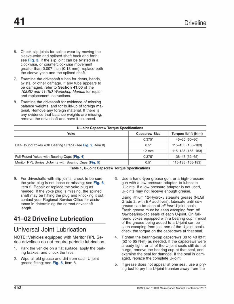
6. Check slip joints for spline wear by moving thesleeve-yoke and splined shaft back and forth;see Fig. 3. If the slip joint can be twisted in aclockwise, or counterclockwise movementgreater than 0.007 inch (0.18 mm), replace boththe sleeve-yoke and the splined shaft.
7. Examine the driveshaft tubes for dents, bends,twists, or other damage. If any tube appears tobe damaged, refer to Section 41.00 of the108SD and 114SD Workshop Manual for repairand replacement instructions.
8. Examine the driveshaft for evidence of missingbalance weights, and for build-up of foreign ma-terial. Remove any foreign material. If there isany evidence that balance weights are missing,remove the driveshaft and have it balanced.
U-Joint Capscrew Torque Specifications
Yoke Capscrew Size Torque: lbf·ft (N·m)
Half-Round Yokes with Bearing Straps (see Fig. 2, item 8)
0.375" 45–60 (60–80)
0.5" 115–135 (155–183)
12 mm 115–135 (155–183)
Full-Round Yokes with Bearing Cups (Fig. 4) 0.375" 38–48 (52–65)
Meritor RPL Series U-Joints with Bearing Cups (Fig. 5) 0.5" 115-135 (155-183)
Table 1, U-Joint Capscrew Torque Specifications
9. For driveshafts with slip joints, check to be surethe yoke plug is not loose or missing; see Fig. 6,item 2. Repair or replace the yoke plug asneeded. If the yoke plug is missing, the splinedshaft may be hitting the plug and knocking it out;contact your Regional Service Office for assis-tance in determining the correct driveshaftlength.
41–02 Driveline Lubrication
Universal Joint LubricationNOTE: Vehicles equipped with Meritor RPL Se-ries drivelines do not require periodic lubrication.
1. Park the vehicle on a flat surface, apply the park-ing brakes, and chock the tires.
2. Wipe all old grease and dirt from each U-jointgrease fitting; see Fig. 6, item 8.
3. Use a hand-type grease gun, or a high-pressuregun with a low-pressure adapter, to lubricateU-joints. If a low-pressure adapter is not used,U-joints may not receive enough grease.
Using lithium 12-Hydroxy stearate grease (NLGIGrade 2, with EP additives), lubricate until newgrease can be seen at all four U-joint seals.Fresh grease must be seen escaping from allfour bearing-cap seals of each U-joint. On full-round yokes equipped with a bearing cup, if mostof the grease being added to a U-joint can beseen escaping from just one of the U-joint seals,check the torque on the capscrews at that seal.
4. Tighten the bearing-cup capscrews 38 to 48 lbf·ft(52 to 65 N·m) as needed. If the capscrews werealready tight, or all of the U-joint seals still do notpurge, remove the bearing cup at that seal, andexamine the seal for damage. If the seal is dam-aged, replace the complete U-joint.
5. If grease does not appear at one seal, use a pry-ing tool to pry the U-joint trunnion away from the
Driveline41
108SD and 114SD Maintenance Manual, September 201541/2

f410067c
1 2
3
3
12/08/2010
45
6
78 9
10
11
12
13
14 15
16
NOTE: Not all fasteners are shown.
1. Transmission2. Transmission Output-Shaft
End-Yoke (half-round)3. U-Joint Assembly4. Bearing Plate Self-Locking
Capscrew5. Bearing Cup (for full-round
yoke)
6. U-Joint Cross7. Bearing Cup (for half-round
yoke)8. Bearing Strap and Bearing-
Strap Capscrew9. Slip-Joint Assembly10. Sleeve-Yoke (full-round)
11. Dust Cap12. Splined Stub Shaft13. Driveshaft Tube14. Tube-Yoke (full-round)15. Axle Input-Shaft End-Yoke
(half-round)16. Rear Axle
Fig. 2, Components of a Basic Driveline
Driveline 41
108SD and 114SD Maintenance Manual, September 2015 41/3

non-purging seal, or tap the driveshaft or yokewith a plastic or rawhide mallet on the side oppo-site the dry seal, while continuing to lubricate. Ifgrease still does not appear, loosen the cap-screws at the bearing with the dry seal, to relieveseal tension. Lubricate the U-joint until newgrease is seen at the seal, then tighten the cap-screws to the correct torque specifications. If thebearing will not take grease, replace the U-joint;see Group 41 of the 108SD and 114SD Work-shop Manual.
6. Check the purged grease. If it appears rusty,gritty, or burned, replace the U-joint.
f410012a10/06/2016
Attempt to move the sleeve-yoke and splined shaft backand forth.
Fig. 3, Slip Joint Spline Wear Checking
f410155a10/06/2016
1
1 1
2
MERI TOR
1. Self-Locking Capscrew2. Adhesive Band
Fig. 4, Meritor U-Joint Fasteners for Full-Round Yokes
f41018210/06/2016
Fig. 5, Meritor RPL Series U-Joint
f410050a10/07/2016
1
1
23
3
34
5
6
7
8
A
A. After grease appears, cover the pressure-relief holewhile continuing to lubricate.
1. Slip Joint Grease Fitting (with grease gun attached)2. Yoke Plug3. Grease4. Half-Round Yoke5. Yoke Plug Pressure-Relief Hole6. Slip Joint Seal7. Full-Round Yoke8. U-Joint Grease Fitting
Fig. 6, Slip Joint and U-Joint Lubrication
Driveline41
108SD and 114SD Maintenance Manual, September 201541/4

7. Wipe the purged grease from the seals, and anyexcess grease from the grease fitting.
Slip Joint Spline LubricationNOTE: Vehicles equipped with Meritor RPL Se-ries drivelines do not require periodic lubrication.
1. If equipped with a grease fitting, wipe all oldgrease and dirt from the slip joint grease fitting;see Fig. 6, item 1.
2. Use a hand-type grease gun or a high-pressuregun with a low-pressure adapter, to lubricate theslip joint. Add multipurpose chassis grease(lithium 12-hydroxy stearate, NLGI Grade 2, withEP additives) until it appears at the pressure-relief hole in the yoke plug. Then cover the reliefhole with your finger, while continuing to applygun pressure until new grease appears at theslip joint seal; see Fig. 6. This ensures completelubrication of the splines.
3. Wipe the purged grease from the pressure-reliefhole and slip joint seal, and any excess greasefrom the grease fitting.
Driveline 41
108SD and 114SD Maintenance Manual, September 2015 41/5

Title of Maintenance Operation (MOP) MOP Number
Air Brake Inspection and Leak Test. . . . . . . . . . . . . . . . . . . . . . . . . . . . . . . . . . . . . . . . . . . . . . . . . . . . . 42–09
Air Brake System Valve Inspection . . . . . . . . . . . . . . . . . . . . . . . . . . . . . . . . . . . . . . . . . . . . . . . . . . . . . 42–01
Air Dryer Check . . . . . . . . . . . . . . . . . . . . . . . . . . . . . . . . . . . . . . . . . . . . . . . . . . . . . . . . . . . . . . . . . . . 42–04
Bendix Air Dryer Desiccant Replacement . . . . . . . . . . . . . . . . . . . . . . . . . . . . . . . . . . . . . . . . . . . . . . . . 42–02
Brake Inspection . . . . . . . . . . . . . . . . . . . . . . . . . . . . . . . . . . . . . . . . . . . . . . . . . . . . . . . . . . . . . . . . . . 42–05
Foot-Control Valve, E-6, Inspection and Lubrication. . . . . . . . . . . . . . . . . . . . . . . . . . . . . . . . . . . . . . . . . 42–08
Governor Check. . . . . . . . . . . . . . . . . . . . . . . . . . . . . . . . . . . . . . . . . . . . . . . . . . . . . . . . . . . . . . . . . . . 42–03
Meritor Camshaft Bracket Lubrication . . . . . . . . . . . . . . . . . . . . . . . . . . . . . . . . . . . . . . . . . . . . . . . . . . . 42–07
Safety Precautions. . . . . . . . . . . . . . . . . . . . . . . . . . . . . . . . . . . . . . . . . . . . . . . . . . . . . . . . . . . . . . . . . 42–00
Slack Adjuster Lubrication. . . . . . . . . . . . . . . . . . . . . . . . . . . . . . . . . . . . . . . . . . . . . . . . . . . . . . . . . . . . 42–06
Versajust Slack Adjuster Inspection and Lubrication. . . . . . . . . . . . . . . . . . . . . . . . . . . . . . . . . . . . . . . . . 42–11
WABCO System Saver Air Dryer Desiccant Cartridge Replacement . . . . . . . . . . . . . . . . . . . . . . . . . . . . . 42–10
Brakes 42Index, Alphabetical
108SD and 114SD Maintenance Manual, December 2015

42–00 Safety PrecautionsSafety Precautions in this section apply to allprocedures within this group.
DANGERWhen working on the vehicle, shut down the en-gine, set the parking brake, and chock the tires.Before working under the vehicle, always placejack stands under the frame rails to ensure thevehicle cannot drop. Failure to follow these stepscould result in serious personal injury or death.
42–01 Air Brake System ValveInspection
IMPORTANT: There is no scheduled (Bendix) airvalve maintenance that requires disassembly ofthe valve within the warranty period. If the valvedoes not function within the warranty period, donot disassemble the part as this will void thewarranty.
See the following maintenance operations forinformation about Bendix air valve maintenance.
42–02 Bendix Air DryerDesiccant Replacement
IMPORTANT: For vehicles equipped with an oil-coalescing air dryer desiccant cartridge, replacethe cartridge once a year, regardless of mileage.
AD–91. Park the vehicle on a level surface, apply the
parking brakes, and chock the tires.
2. Completely drain all air reservoirs. Air pressuregauges should read 0 psi (0 kPa).
NOTE: The compressor discharge line may stillcontain residual air pressure, open the lineslowly.
3. Identify, tag, and disconnect the three air linesfrom the end cover.
4. Disconnect the harness connector from theheater and thermostat assembly.
5. Loosen the bolt that secures the upper mountingbracket strap.
6. Remove the two bolts and Nylok® nuts that se-cure the air dryer to the lower mounting bracket.Mark the position of the mounting bracket to theend cover and mark the bolts to ease installation.
7. Remove the upper mounting bracket strap fas-teners, then remove the strap and the air dryer.
8. Place the air dryer on a bench and remove theremaining 6 bolts, 12 washers, 6 Nylok nuts, andthe air dryer housing. See Fig. 1. Discard theNylok nuts. Remove the end-cover-to-housingO-ring.
9. Clamp the desiccant cartridge in a vise.
WARNINGClamping the end cover or housing in a vise couldseriously compromise the air dryer’s ability tohold air pressure, which could cause a failure inthe brake system, resulting in property damage,personal injury, or death.
10. Twist the end cover counterclockwise to releasethe cartridge from the end cover. Rotate the endcover until it completely separates from the des-iccant cartridge.
NOTE: A substantial torque, up to 50 lbf·ft (68N·m), may be necessary to remove the desic-cant cartridge.
NOTICEDirt or obstructions in the O-ring grooves cancause an O-ring failure that will result in an airleak.
11. Inspect the condition of the O-ring seals. If theyare cracked, crimped, or otherwise damaged,replace them to ensure an airtight seal. Cleanthe O-ring grooves of any dirt or obstruction.
12. Lubricate the O-rings with silicone or lithiumgrease and install them in the end cover.
13. Install the desiccant cartridge on the end cover.Turn the cartridge clockwise until the desiccantcartridge makes contact with the end cover.
Brakes 42
108SD and 114SD Maintenance Manual, December 2015 42/1

14. Place the desiccant cartridge in a vise, and turnthe end cover clockwise an additional 180 to 225degrees to fully tighten the desiccant cartridge tothe end cover.
NOTE: Desiccant cartridge torque should notexceed 50 lbf·ft (68 N·m).
15. Place the housing over the desiccant cartridgeand align the mounting holes with the end cover.
IMPORTANT: Replace, do not reuse the Nyloknuts on the air dryer cover.
16. Install the 6 bolts, 12 washers, and 6 new Nyloknuts. Torque the Nylok nuts in a star pattern 17to 24 lbf·ft (23 to 33 N·m). See Fig. 2.
17. Install the air dryer on the lower mountingbracket. Install the two previously marked bolts,four washers, and two new Nylok nuts. Torquethe two remaining Nylok nuts 17 to 24 lbf·ft (23
08/09/95 f421383
1
2
34
5
9
10
11
12
13
14
15
1718 19
21
22
23
24
25
10
1010
1010
106
78
8
8
20
16
1. 5/16 x 4-1/2 Upper MountingBracket Bolt
2. Upper Mounting Bracket Strap3. Lockwasher4. 5/16-Inch Nylok Nut5. Upper Mounting Bracket6. Housing7. Nylok Nut8. 3/8-Inch Special Washer
9. Desiccant Cartridge10. O-Ring11. Safety Valve12. Lower Mounting Bracket13. 3/8-Inch Bolt (long)14. Check Valve Assembly15. Purge Valve Assembly16. Purge Valve Capscrew17. Exhaust Diaphragm
18. Purge Valve19. 1/4-Inch Tapping Screw20. Purge Valve Housing21. Heater and Thermostat
Housing22. Return Spring23. Purge Piston24. 3/8-Inch Bolt25. End Cover
Fig. 1, AD–9 Air Dryer (exploded view)
Brakes42
108SD and 114SD Maintenance Manual, December 201542/2

to 33 N·m). Install the bolt, two washers, and anew Nylok nut in the upper mounting bracketstrap. Torque the upper mounting bracket strapNylok nut 80 to 120 lbf·in (900 to 1360 N·cm).
18. Connect and tighten the three air lines. Connectthe harness connector to the heater and thermo-stat assembly until the lock tab snaps in place.
19. Start the engine, build the air pressure, andcheck the air brake system for leaks. If any airleaks are present, see Group 42 of the vehicleWorkshop Manual for diagnosis and repairinformation.
AD–IP1. Park the vehicle on a level surface, apply the
parking brakes, and chock the tires.
2. Using a wrench or a socket, loosen the desiccantcartridge bolt. Then separate the desiccant car-tridge from the end cover.
3. Pull the cartridge bolt out of the cover and re-move the cartridge.
WARNINGDo not attempt to disassemble the desiccant car-tridge assembly. Parts for the assembly are notavailable and the cartridge contains a 150 lb
spring that cannot be mechanically caged. Disas-sembly could release the spring, resulting in per-sonal injury.
4. Remove and discard both O-rings from the car-tridge bolt.
5. Using a clean rag, wipe clean the inside of theend cover. Clean the cartridge bolt bore in theend cover, and the sealing surfaces for the large-and small-diameter desiccant cartridge sealingrings.
6. Inspect the end cover for physical damage, theninspect all air line fittings for corrosion; replaceas necessary.
7. Clean and inspect the bolt, paying attention tothe threads and O-ring grooves.
IMPORTANT: Use only the grease supplied withBendix replacement kits.
8. Lubricate the O-rings, bolt O-ring grooves, seal-ing rings, and cartridge grooves. Lubricate theend cover bore for the bolt.
9. Install both O-rings on the cartridge bolt, then,using a twisting motion, insert the assembleddesiccant cartridge bolt in the end cover.
10. Install the desiccant cartridge on the end cover,making sure the cartridge is properly seated andflush on the end cover.
NOTE: It may be necessary to rotate the car-tridge slightly until the anti-rotation lugs areproperly aligned and allow the cartridge to restflush against the end cover.
11. Using a wrench or socket, tighten the desiccantcartridge bolt 70 lbf·ft (95 N·m). Do not over-torque.
12. Before placing the vehicle in service, perform thetest below.
12.1 Close all reservoir drain cocks.
12.2 Build system pressure to governor cut-out, and note that the AD-IP air dryerpurges with an audible escape of air.
12.3 Fan the service brakes to reduce systemair pressure to governor cut-in. Note thatthe system once again builds to full pres-sure and is followed by a purge at theAD-IP air dryer exhaust.
f420544a
1 & 9
2
3
4 5
6
7 8
09/20/94
Fig. 2, AD–9 End Cover to Housing Torque Pattern
Brakes 42
108SD and 114SD Maintenance Manual, December 2015 42/3

12.4 Check for excessive leakage around thehead of the desiccant cartridge where itcontacts the end cover. With the com-pressor in loaded mode (compressingair), apply a soapy solution to theseareas, and observe that any leakagedoes not exceed a 1-inch bubble in 1second. If leakage exceeds this measure,remove and re-install the desiccantcartridge.
AD-9si and AD–IS1. Park the vehicle on a level surface, apply the
parking brakes, and chock the tires.
2. Drain the air reservoirs.
3. Using a strap wrench or equivalent, loosen thedesiccant cartridge. Spin the cartridge off byhand and discard it. See Fig. 3.
4. On the new desiccant cartridge, lubricate thesealing rings with silicone grease.
IMPORTANT: Only use the silicone grease sup-plied with Bendix replacement kits.
5. Screw the desiccant cartridge onto the body byhand until the seal makes contact with the body.Rotate the cartridge clockwise about one fullturn. Tighten the cartridge firmly.
42–03 Governor CheckIMPORTANT: Review the warranty policy beforeperforming any intrusive maintenance proce-dures. An extended warranty may be voided ifintrusive maintenance is performed during thisperiod.
Every 12 months, 100,000 miles (160 900 km), or3600 operating hours, perform the operational testbelow.
Operational Test1. Start the vehicle engine, build air pressure in the
brake system, and check the pressure registeredby a dash or test gauge at the time the governorcuts-out, stopping the compression of air by thecompressor. Cut-out pressure should be in ac-cordance with the pressure setting of the piecenumber being used. Common cut-out pressuresare 125 to 135 psi (862 to 931 kPa). With theengine still running, make a series of brake appli-cations to reduce the air pressure, and observeat what pressure the governor cuts-in the com-pressor. As in the case of cut-out pressure, cut-inpressure should be in accordance with the pres-sure setting of the piece number being used.Common cut-in pressure is 105 psi (724 kPa).
NOTE: If the governor cover is marked nonad-justable, and the adjusting stem has beensheared off, this is a non-serviceable governorand it must be replaced with a new or remanu-factured unit.
2. Never condemn or adjust the governor pressuresettings unless they’re checked with an accuratetest gauge or a dash gauge that’s registering ac-curately. If the pressure settings of the D-2 gov-ernor are inaccurate or it’s necessary that theybe changed, the adjustment procedure follows.
2.1 Remove the top cover from the governor.
2.2 Loosen the adjusting screw locknut.
2.3 To raise the pressure setting, turn the ad-justing screw counterclockwise; to lowerthe setting, turn the screw clockwise. Becareful not to overadjust. Each 1/4 turn ofthe adjusting screw raises or lowers thepressure setting approximately 4 psi (28kPa).
f42191010/07/2016
1
2
3
1. Desiccant Cartridge2. Cartridge Sealing Ring3. Threaded Base Post
Fig. 3, Desiccant Cartridge Replacement
Brakes42
108SD and 114SD Maintenance Manual, December 201542/4

2.4 When proper adjustment is obtained,tighten the adjusting screw locknut, andinstall the top cover. The pressure rangebetween cut-in and cut-out is not adjust-able.
Cut-In PositionApply soap solution around the cover and to the ex-haust port. Slight bubble leakage is permitted. Exces-sive leakage indicates a faulty inlet valve or faultylower piston O-ring.
Cut-Out PositionApply soap solution around the cover and to the ex-haust port. Slight bubble leakage is permitted. Exces-sive leakage indicates a faulty exhaust valve seat,exhaust stem O-ring, or O-ring at the top of thepiston.
If the governor does not function as described, or ifleakage is excessive, it is recommended that it bereplaced with a new or remanufactured unit, or re-paired with genuine Bendix parts.
42–04 Air Dryer CheckThe information in this MOP applies to Bendix AD-9,AD-IP, and AD-IS/DRM air dryers.
IMPORTANT: Review the warranty policy beforeperforming any intrusive maintenance proce-dures. An extended-warranty may be voided ifintrusive maintenance is performed during thisperiod.
Because no two vehicles operate under identicalconditions, maintenance and maintenance intervalswill vary. Experience is a valuable guide in determin-ing the best maintenance interval for any one particu-lar operation.
Every 900 operating hours, or 25,000 miles (40 225km), or 3 months:
1. Check for moisture in the air brake system byopening reservoir drain valves and checking forthe presence of water. If moisture is present, thedesiccant cartridge may require replacement;however, the following conditions can also causewater accumulation and should be consideredbefore replacing the desiccant:
1.1 An outside air source has been used tocharge the system. This air did not passthrough the drying bed.
1.2 Air usage is exceptionally high and notnormal. This may be due to high air sys-tem leakage.
1.3 In areas where more than a 30-degreerange of temperature occurs in one day,small amounts of water can temporarilyaccumulate in the air brake system due tocondensation. Under these conditions, thepresence of small amounts of moisture isnormal.
NOTE: A small amount of oil in the system isnormal and should not be considered as a rea-son to replace the desiccant cartridge. Some oilat the dryer exhaust is normal.
2. Visually check for physical damage such aschaffed or broken air and electrical lines and bro-ken or missing parts.
3. Check mounting bolts for tightness. Tighten 30 to35 lbf·ft (41 to 47 N·m).
4. Perform the operational and leakage tests listedbelow.
Operational and Leakage Tests1. Check all lines and fittings leading to and from
the air dryer for leakage and integrity. Repair anyleaks found.
2. Build system pressure to governor cutout, andnote that the dryer purges with an audible es-cape of air. Watch the system pressure and notethe pressure fall-off for a 10-minute period. If thepressure drop exceeds 1 psi/minute from eitherservice reservoir for a single vehicle; or 3psi/minute for a tractor trailer, inspect the vehicleair systems for sources of leakage, and repairthem. Refer to troubleshooting information inBendix service literature.
3. Check for excessive leakage around the purgevalve with the compressor in the loaded mode(compressing air). Apply a soap solution to thepurge valve exhaust port and observe that leak-age does not exceed a 1-inch (25-mm) bubble in1 second. If the leakage exceeds the maximumspecified, refer to troubleshooting information inthe Bendix service literature.
Brakes 42
108SD and 114SD Maintenance Manual, December 2015 42/5

4. Build system pressure to governor cutout, andnote that the dryer purges with an audible es-cape of air. Fan the service brakes to reducesystem air pressure to governor cut-in. Note thatthe system once again builds to full pressure andis followed by a dryer purge. If the system doesnot follow this pattern, refer to troubleshootinginformation in the Bendix service literature.
5. Check operation of the end cover heater andthermostat assembly during cold weather, as fol-lows:
5.1 Electric Power to the Dryer: With the igni-tion or engine kill switch in the ON posi-tion, check for voltage to the heater andthermostat assembly using a voltmeter ortestlight. Unplug the electrical connectorat the air dryer and place the test leadson each of the connections of the femaleconnector on the vehicle power lead. Ifthere is no voltage, look for a blown fuse,broken wires, or corrosion in the vehiclewiring harness. Check to see if a goodground path exists.
5.2 Thermostat and Heater Assembly Opera-tion: These tests are not possible exceptin cold-weather operation. Turn off theignition switch, and cool the thermostatand heater assembly to below 40°F(4°C). Using an ohmmeter, check resis-tance between the electrical pins in theair dryer connector half. Resistanceshould be 1.5 to 3.0 ohms for the 12-voltheater assembly, and 6.0 to 9.0 ohms forthe 24-volt heater assembly.
NOTE: Some models of the AD-9 mayhave a resistance reading of 1.0 to 2.5ohms.
Warm the thermostat and heater assem-bly to approximately 90°F (32°C) andagain check the resistance. Resistanceshould exceed 1000 ohms. If resistancevalues obtained are within stated limits,the thermostat and heater assembly isoperating properly. If resistance valuesobtained are outside stated limits, replacethe heater and thermostat assembly.
6. On the AD-IS/dryer reservoir module (DRM) only,observe the pressure gauges of the vehicle assystem pressure builds from zero. The primarygauge should rise until it reaches approximately
109±5 psi (751 ±34 kPa), then level off (or a mo-mentary slight fall) as the second pressure pro-tection valve opens supplying the secondary res-ervoir. When the secondary pressure gaugepasses through approximately 55 ±5 psi (379±34 kPa) and then 85 ±5 psi (586 ±34 kPa)there should be an associated levelling off (ormomentary slight fall) of pressure as the thirdand fourth pressure protection valves open. Fi-nally, both the primary and secondary gaugesshould reach their full pressure of approximately130 ±5 psi (896 ±34 kPa). If the AD-IS does notperform within the pressure ranges describedabove, recheck using gauges known to be accu-rate. If readings remain outside the ranges out-lined above, replace the AD-IS.
There are no kits available for servicing the pres-sure protection valves.
WARNINGDo not attempt to adjust or service the pressureprotection valves. Incorrect pressure protectionvalve settings can result in automatic applicationof the vehicle spring brakes without prior warning.This can cause personal injury or property dam-age.
42–05 Brake InspectionIMPORTANT: This procedure should be per-formed prior to lubrication of the brake compo-nents.
Parking Brake Operational Check
CAUTIONPerform the following check in a clear, safe area. Ifthe parking brakes fail to hold the vehicle, per-sonal injury or property damage may result.
1. With the engine running, and air pressure at cut-out pressure, set the parking brake.
2. Put the vehicle in the lowest gear and gently at-tempt to move it forward. The vehicle should notmove. If the vehicle moves, the parking brakesare not operating correctly and must be repairedbefore the vehicle is returned to service. See
Brakes42
108SD and 114SD Maintenance Manual, December 201542/6

Group 42 of the 108SD and 114SD WorkshopManual for repair procedures.
Brake Component Inspection1. Park the vehicle on a level surface, set the park-
ing brake, and chock the tires. Once the tires arechocked, release the parking brake.
WARNINGManually adjusting an automatic slack adjuster tobring the pushrod stroke within legal limits islikely masking a mechnical problem. Adjustmentis not repairing. Before adjusting an automaticslack adjuster, troubleshoot the foundation brakesystem and inspect it for worn or damaged com-ponents. Improperly maintaining the vehicle brak-ing system may lead to brake failure, resulting inproperty damage, personal injury, or death.
2. With the engine off, and 100 psi (689 kPa) of airtank pressure, have an assistant apply and holdan 80 to 90 psi (550 to 620 kPa) brake applica-tion.
3. Check to see if the colored over-stroke band oneach brake chamber pushrod is exposed.
If a band shows, the stroke is too long. Checkthe foundation brake components for wear ordamage, and repair as needed. See Group 42 ofthe 108SD and 114SD Workshop Manual for in-spection, troubleshooting, and repair procedures.
4. Measure the applied chamber stroke. SeeTable 1 for the proper stroke for the type ofchamber being used. If the stroke is too short,the brakes may drag or will not fully apply. Checkfor improper operation or adjustment of the auto-matic slack adjuster. See Group 42 of the108SD and 114SD Workshop Manual for inspec-tion and troubleshooting procedures.
5. Start the engine and build air pressure to at least100 psi (689 kPa). Shut down the engine.
6. Check all of the foundation brake components fordamage, wear, and loose or missing parts. Re-pair as needed. See Group 42 of the 108SD and114SD Workshop Manual for repair procedures.
Brake Chamber Stroke Specifications
ChamberMax Applied Stroke: inch (mm)
Manufacturer Type* Size†
Gunite
Standard Stroke
91-3/8 (35)
12
16
1-3/4 (45)20
24
30 2 (51)
36‡ 2-1/4 (57)
Long Stroke
16
2 (51)20
24
242-1/2 (64)
30
Brakes 42
108SD and 114SD Maintenance Manual, December 2015 42/7

Brake Chamber Stroke Specifications
ChamberMax Applied Stroke: inch (mm)
Manufacturer Type* Size†
Haldex
Standard Stroke
12 1-3/8 (35)
16
1-3/4 (44)20
24
2-1/2-Inch Extended Stroke 24 2 (51)
3-Inch Extended Stroke 24 2-1/2 (64)
Standard Stroke 30 2 (51)
Long Stroke 30 2-1/2 (64)
Meritor
Standard Stroke
9Less than 1-1/2 (38)
12
16Less than 1-3/4 (44)
20
24 Less than 1-7/8 (48)
Long Stroke 24Less than 2 (51)
Standard Stroke 30* Long stroke design is indicated by a tag, or embossing, on the brake chamber.† Specifications are relative to a brake application with 80 to 90 psi (550 to 620 kPa) air pressure in the brake chambers.‡ If type 36 chamber is used, slack length should be less than 6 inches.
Table 1, Brake Chamber Stroke Specifications
42–06 Slack AdjusterLubrication
IMPORTANT: Perform MOP 42-05 before lubri-cating the slack adjusters.
Automatic slack adjusters that have a grease fittingmust be lubricated periodically to ensure properbrake operation.
WARNINGFailure to lubricate slack adjusters could lead todragging brakes or a brake failure, resulting inproperty damage, personal injury, or death.
MeritorNOTE: If equipped with an extended-maintenance Q Plus™ brake system, the slackadjuster will not have a grease fitting. These
slack adjusters use a special NLGI grade syn-thetic polyurea grease, and do not require lubri-cation for 3 years or 500,000 miles (800 000km), whichever comes first. Extended-maintenance slack adjusters are lubricated dur-ing the brake reline service interval. For serviceand lubrication instructions, see Group 42 ofthe 108SD and 114SD Workshop Manual.
For slack adjusters with grease fittings and for oper-ating temperatures above –40°F (–40°C), use anNLGI Grade 1 clay-base grease or an NLGI Grade 1or 2 lithium-base grease.
For slack adjusters with grease fittings, and for oper-ating temperatures below –40°F (–40°C) and above–65°F (–54°C), use an NLGI Grade 2 synthetic oil ora clay-base grease.
Lubricate the slack adjuster at the grease fitting untilgrease is forced past the pressure-relief capscrew orpast the gear splines around the inboard snap ring.See Fig. 4.
Brakes42
108SD and 114SD Maintenance Manual, December 201542/8

Haldex
NOTICEDo not use moly-disulfide-loaded grease or oil.Both the life and reliability of the slack adjusterwill be reduced if this type of grease is used.
Lubricate the automatic slack adjuster at the greasefitting. See Fig. 5. Use standard chassis lubricant forHaldex slack adjusters.
GuniteFor operating temperatures of –20°F (–29°C) andhigher, use Texaco Multifak EP-2 or Mobil GreaseNo. 77.
For operating temperatures between –20°F (–29°C)and –40°F (–40°C), use Lubriplate Aero grease.
Lubricate a Gunite automatic slack adjuster at thegrease fitting until grease appears on the camshaft,or flows from the grease relief. See Fig. 6.
Gunite automatic slack adjusters are produced with-out a grease relief. During lubrication with a greasegun, the lubricant is forced through the drilled worm
wheel onto the camshaft. Lubricate the automaticslack adjuster at the grease fitting until grease ap-pears on the camshaft. See Fig. 7.
42–07 Meritor CamshaftBracket Lubrication
IMPORTANT: Perform MOP 42-05 before lubri-cating the camshaft brackets.
NOTE: If equipped with an extended-maintenance Q Plus™ brake system, the cam-shaft bracket will not have a grease fitting.These camshafts use a special NLGI grade syn-thetic polyurea grease, and do not require lubri-cation for 3 years or 500,000 miles (800 000km), whichever comes first. Extended-maintenance camshaft bushings are lubricatedduring the brake reline service interval. For ser-vice and lubrication instructions, see Group 42of the 108SD and 114SD Workshop Manual.
For camshaft brackets with grease fittings, use anNLGI Grade 1 or Grade 2 multipurpose chassis
f420012a10/20/93
1
2
3
4
5
6
7
1. Brake Chamber2. Clevis3. Actuator Rod4. Boot5. Pull-Pawl Seal6. Manual Adjusting Nut7. Grease Fitting (or plug)
Fig. 4, Meritor Automatic Slack Adjuster
02/01/2001
1
2
f421649a
1. Grease Fitting 2. Slack Adjuster
Fig. 5, Haldex Slack Adjuster Grease Fitting
Brakes 42
108SD and 114SD Maintenance Manual, December 2015 42/9

grease. Lubricate the camshaft bushings through thegrease fitting on the camshaft bracket or the spideruntil new grease flows from the inboard seal. SeeFig. 8.
WARNINGIf grease leaks out under the camhead, the cam-shaft bracket grease seal is worn or damaged. SeeGroup 42 of the 108SD and 114SD WorkshopManual for grease seal replacement instructions. Ifthis seal is not replaced, the brake linings couldbecome contaminated with grease. The stopping
distance of the vehicle will be increased, whichcould result in personal injury or property dam-age.
f420653a
1
2
3
45
6
7
8
10
9
10/27/93
1. 7/16-Inch Adjusting Nut2. Grease Fitting3. Boot4. Link5. Brake Chamber Piston Rod6. Clevis7. 1/2-Inch Clevis Pin8. 1/4-Inch Clevis Pin9. Grease Relief Opening10. Slack Adjuster Spline
Fig. 6, Gunite Automatic Slack Adjuster
f420011a10/07/2016
1
2
3
A
A. Grease Exit1. Brake Chamber2. Slack Adjuster3. Non-Pressure-Relief Grease Fitting
Fig. 7, Camshaft Bracket Lubrication
f420011a10/07/2016
1
2
3
A
A. Grease Exit1. Brake Chamber2. Slack Adjuster3. Non-Pressure-Relief Grease Fitting
Fig. 8, Camshaft Bracket Lubrication
Brakes42
108SD and 114SD Maintenance Manual, December 201542/10

42–08 Foot-Control Valve, E-6,Inspection andLubrication
1. Remove the brake valve from the vehicle. SeeSection 42.08, Subject 110 of the 108SD and114SD Workshop Manual for instructions.
2. Remove the roll pin from the brake pedal pivotpin. See Fig. 9.
3. Remove the brake pedal pivot pin.
4. Remove the brake pedal.
5. Check the brake pedal mounting plate adapterfor signs of wear or cracks at the bosses (thearea from which the pivot pin was removed). Re-place it as needed.
6. Check the brake pedal rollers for signs of wearor cracks. Replace the rollers as needed.
7. If the rollers are replaced, replace the roller pin,install a new cotter pin, bend it 90 degrees, andapply Torque Seal (OPG F900 White) to the cot-ter pin.
8. Remove the plunger from the valve. Clean theexisting grease from the plunger, using alcohol.Check the plunger for signs of wear or cracks.Replace it as needed.
9. Lubricate the plunger with synthetic grease ofNLGI Grade 1.5, such as 76 Triton synthetic EPGrease (FTL Sped 48-25432-000).
10. Insert the plunger in the valve.
11. Install the brake pedal with the pivot pin.
12. Install a new roll pin, then apply Torque Seal(OPG F900 White) to the roll pin.
13. Install the brake valve assembly. See Section42.08, Subject 110 of the 108SD and 114SDWorkshop Manual for instructions.
14. Test the brakes before returning the vehicle toservice.
42–09 Air Brake Inspection andLeak Test
IMPORTANT: If any of the tests in the followingprocedure fail, refer to Group 42 of the 108SDand 114SD Workshop Manual to test individualair brake components and valves.
WARNINGSome steps in this operation require the parkingbrakes to be released. Make sure the vehicle is ona level surface and all tires are chocked. Failure todo so could result in the vehicle rolling, causingpersonal injury and/or vehicle damage.
1. With the vehicle parked on a level surface, shutdown the engine, apply the parking brakes, andchock all tires.
2. Completely drain all air reservoirs.
3. Install accurate test gauges in the primary andsecondary reservoirs.
4. Start the engine and run it at a fast idle.
5. Record reservoir pressures when the low-pressure warning turns off.
6. Record governor cut-out pressure and air dryerpurge pressure.
09/10/2004 f430405
1
2
3
4
6
78
5
1. Foot-Control Valve,E-6
2. Mounting Plate3. Nut and Washer4. Pivot Pin
5. Roll Pin6. Roller7. Roller Pin8. Pedal
Fig. 9, Brake Pedal and Valve Assembly
Brakes 42
108SD and 114SD Maintenance Manual, December 2015 42/11

7. Reduce service air pressure by applying and re-leasing the service brakes several times, andrecord governor cut-in pressure.
8. Charge the air system to governor cut-out, shutdown the engine, and apply the parking brakes.
9. Allow pressure to stabilize for one minute.
10. Observe the installed service reservoir gauges.The pressure should not drop more than 10 psi(69 kPa) within five minutes.
11. If necessary, start the engine and charge the airsystem. Shut down the engine and release theparking brakes.
12. Make and hold a full service brake application,allowing the pressure to stabilize for one minute.Observe the installed service reservoir gauges.The pressure should not drop more than 15 psi(103 kPa) in five minutes.
13. With the air system at full pressure and the en-gine idling, perform the following:
• On trucks, operate the parking brake con-trol valve and note that the parking brakesapply and release promptly as the controlvalve knob is pulled out and pushed in onthe spring brake axles only.
• On tractors, operate the trailer supply con-trol valve knob. Note the air coming out ofthe trailer control coupling. Operate thepark control knob and note that the parkingbrakes apply and release promptly as theknob is pulled out and pushed in. Block thetrailer supply coupling, and push the trailersupply control valve and park control valveknobs in. When the park control valve knobis pulled out, the trailer supply knob shouldalso come out.
14. Build air system pressure to cut-out and shutdown the engine.
15. Completely drain the secondary (front axle) res-ervoir. On vehicles equipped with a Dryer Reser-voir Module (DRM) or AD-IS with the air dryerattached to the reservoir, the primary (rear axle)reservoir pressure should not drop below 65 psi(448 kPa). On vehicles equipped with singlecheck valves, where the air dryer is not attachedto the reservoir, the primary reservoir should notlose pressure.
16. Make a service brake application. The rear axlebrakes should apply and release and the brakelights should illuminate.
On tractors, with the trailer supply knob pushedin, the trailer control coupling should deliver airduring the brake application.
17. Push the trailer air supply valve knob in. With thesecondary reservoir still completely drained,slowly drain the primary reservoir and record thepressure at which the knob automatically comesout. This pressure should be 20 to 45 psi (138 to310 kPa).
18. Close the drain cocks, recharge the system, andcompletely drain the primary reservoir. On ve-hicles equipped with a DRM or AD-IS with the airdryer attached to the reservoir, the secondaryreservoir pressure should not drop below 65 psi(448 kPa). On vehicles equipped with singlecheck valves, where the air dryer is not attachedto the reservoir, the secondary reservoir shouldnot lose air pressure.
19. On tractors only:
19.1 Start the engine and build the system airpressure to governor cut-out.
19.2 Shut down the engine and leave the park-ing brakes released.
19.3 Completely drain the primary reservoir.
19.4 Make a modulated service brake applica-tion by depressing the brake pedal. Thefront brakes should apply and releaseand the brake lights should illuminate. Inaddition to the front brakes, with thetrailer supply knob pushed in, the trailercontrol coupling should deliver air duringthe brake application.
20. On trucks only:
20.1 Start the engine and charge the air sys-tem until governor cut-out.
20.2 Shut down the engine and leave the park-ing brakes released.
20.3 Completely drain the primary reservoir.
20.4 Make a modulated service brake applica-tion. Both front and rear brakes shouldmodulate. At a steady full brake applica-tion, the pressure should not drop morethan 10 psi (69 kPa) within five minutes.
Brakes42
108SD and 114SD Maintenance Manual, December 201542/12

21. Drain all reservoirs and remove the gauges fromthe service reservoirs. Close the reservoir draincocks.
22. Remove the chocks from the tires.
42–10 WABCO System SaverAir Dryer DesiccantCartridge Replacement
NOTE: The following instructions apply to theSystem Saver 1200 Plus and Twin air dryers.
NOTICEThe WABCO System Saver air dryers can use ei-ther a standard or oil coalescing desiccant car-tridge. When replacing the desiccant cartridge, itis very important to use the same type of car-tridge that was originally installed on the dryer. Oilcoalescing cartridges can be used in any applica-tion, but require more frequent service intervals(every 1 to 2 years instead of every 2 to 3 yearsfor a standard cartridge). Do not replace an oil co-alescing cartridge with a standard cartridge, asthis may result in contamination and malfunction-ing of downstream air system components.
Refer to Fig. 10 for cartridge replacement.
1. Drain the air system.
2. Using a strap wrench, turn the desiccant car-tridge counterclockwise and remove it.
3. Remove and discard the O-ring.
4. Clean the top surface of the dryer base with acommercial cleaning solvent.
IMPORTANT: If the air dryer base is damaged,preventing a tight seal, replace the air dryer.
5. Using a multipurpose, high-temperature greasethat resists water, steam, and alkali, lightly coatthe surfaces of the new O-ring and the dryerbase. Install the O-ring.
6. Thread the desiccant cartridge onto the dryerbase (turn clockwise). When the seal contactsthe base, tighten the cartridge one complete turnmore. Do not overtighten.
42–11 Versajust Slack AdjusterInspection andLubrication
IMPORTANT: Perform the Brake Inspectionmaintenance operation before lubricating theslack adjusters.
1. Visually check for physical damage, such as bro-ken air lines and broken or missing parts.
2. Using a quality multipurpose chassis lubricant,NLGI Grade 2, lubricate the slack adjusterthrough the grease fitting until clean lubricantflows from the grease relief opening in the boot.
3. Perform the "In Service Inspection."
In Service Inspection1. Apply and release the brakes several times while
observing the slack adjuster. The slack adjusterand brake actuator should move freely, withoutbinding or interference, and should return to thefull released position. Observe the looseness thatexists between the clevis and adapter bushingand the yoke and link pins and their mating parts
f42129210/07/2016
1
2
3
1. Seal2. O-Ring
3. Air Dryer Base
Fig. 10, Desiccant Cartridge Replacement
Brakes 42
108SD and 114SD Maintenance Manual, December 2015 42/13

(clevis, body, link). Replace these parts if loose-ness appears excessive. Make certain the brakeactuator pushrod jam nut is tightened securely.
2. Inspect the slack adjuster for physical damage,paying attention to the link, boot, and clevis. Ifany components are damaged, repair or replacethem as necessary.
3. Measure the brake actuator pushrod stroke whilemaking an 80 to 90 psi (552 to 621 kPa) brakeapplication. Actuator pushrod strokes should notexceed the values shown in Table 2 andTable 3. To achieve the correct pressure for thistest, build the system pressure up to a 100 psi(690 kPa). Shut down the engine. Fan thebrakes to attain a 90 to 95 psi (621 to 655 kPa)reading. Make and hold a full brake applicationwhile the strokes are checked.
Actuator Stroke–Standard Stroke
Brake Actuator Size Recommended MaximumOperating Stroke (Inches)
30 2
24 1-3/4
20 1-3/4
16 1-3/4
12 1-3/8
Table 2, Actuator Stroke–Standard Stroke
Actuator Stroke–Long Stroke
Brake Actuator Size Recommended MaximumOperating Stroke (Inches)
30 Long Stroke 2-1/2
24 Long 2
24 Long Stroke 2-1/2
20 Long 2
16 Long 2
Table 3, Actuator Stroke–Long Stroke
Brakes42
108SD and 114SD Maintenance Manual, December 201542/14

Title of Maintenance Operation (MOP) MOP Number
Drag Link Inspection. . . . . . . . . . . . . . . . . . . . . . . . . . . . . . . . . . . . . . . . . . . . . . . . . . . . . . . . . . . . . . . . 46–01
Drag Link Lubrication . . . . . . . . . . . . . . . . . . . . . . . . . . . . . . . . . . . . . . . . . . . . . . . . . . . . . . . . . . . . . . . 46–05
Power Steering Fluid Level Inspection. . . . . . . . . . . . . . . . . . . . . . . . . . . . . . . . . . . . . . . . . . . . . . . . . . . 46–03
Power Steering Fluid and Filter Change . . . . . . . . . . . . . . . . . . . . . . . . . . . . . . . . . . . . . . . . . . . . . . . . . 46–02
Power Steering Gear Lubrication. . . . . . . . . . . . . . . . . . . . . . . . . . . . . . . . . . . . . . . . . . . . . . . . . . . . . . . 46–04
Safety Precautions. . . . . . . . . . . . . . . . . . . . . . . . . . . . . . . . . . . . . . . . . . . . . . . . . . . . . . . . . . . . . . . . . 46–00
Steering 46Index, Alphabetical
108SD and 114SD Maintenance Manual, September 2015

46–00 Safety PrecautionsSafety Precautions in this section apply to allprocedures within this group.
DANGERWhen working on the vehicle, shut down the en-gine, set the parking brake, and chock the tires.Before working under the vehicle, always placejack stands under the frame rails to ensure thevehicle cannot drop. Failure to follow these stepscould result in serious personal injury or death.
46–01 Drag Link Inspection
WARNINGAll steering system components are critical forsafe operation of the vehicle. Failure to maintainthe steering system as specified may result inloss of steering control, which could lead to per-sonal injury and property damage.
Have someone turn the steering wheel from left toright. As the steering wheel is turned, check forlooseness between the ball stud and the pitman arm,and between the other ball stud and the steeringarm. Check for loose ball stud castle nuts. SeeFig. 1.
If there is looseness in either ball stud end, replacethe drag link. See Section 46.03 of the 108SD and114SD Workshop Manual for replacement instruc-tions. If there is 1/8-inch (3-mm) movement or more,do not drive the vehicle until the drag link is re-placed.
If a ball stud nut is loose, replace the nut and cotterpin. See Section 46.03 of the 108SD and 114SDWorkshop Manual for torque specifications.
Inspect the drag link boots (at both the pitman armand the steering arm ends) for cracks, splits, or otherdamage. Replace boots as needed. See Section46.03 of the 108SD and 114SD Workshop Manualfor drag link removal and installation instructions.
46–02 Power Steering Fluidand Filter Change
WARNINGFill only with approved clean fluid. Failure to usethe proper fluid could cause seal deterioration andleaks. Fluid leaks could eventually cause loss ofpower steering assist. This could lead to an acci-dent resulting in personal injury or property dam-age. Wear eye protection when changing the fluidand filter.
1. Park the vehicle on a level surface, shut downthe engine, apply the parking brakes, and chockthe rear tires.
2. Place a drain pan under the power steering res-ervoir.
12/14/2010 f462186a
1
2
3
4
5
5
4
6
7
7
8
8
1. Steering Gear2. Pitman Arm3. Drag Link4. Cotter Pin
5. Castle Nut6. Steering Arm7. Ball Stud8. Boot
Fig. 1, Drag Link Assembly
Steering 46
108SD and 114SD Maintenance Manual, September 2015 46/1

3. Remove the retaining ring from the reservoir.See Fig. 2.
4. Remove the filter, filter cover, and gasket fromthe reservoir. Drain the fluid from the filter intothe drain pan. Leave the filter hanging over thedrain pan.
5. Remove the nuts, bolts, and washers that attachthe power steering reservoir to the mountingbracket, but do not remove the supply line to thereservoir. Drain the power steering fluid from thereservoir.
6. Using bolts, nuts, and washers, attach the reser-voir to the mounting bracket.
7. Using ATF fluid that meets Dexron III or TES-389specifications, fill the reservoir to the line be-tween the MIN COLD and MAX HOT lines. SeeFig. 2.
8. Raise the front of the vehicle and support it withjack stands.
9. Start the engine and operate it at idle. Turn thesteering wheel from full left to full right severaltimes until clean fluid starts flowing from thepower steering filter. Add fluid to the reservoir tomaintain the fluid level between the MIN COLDand MAX HOT lines.
10. Shut down the engine.
NOTE: Always install a new power steering res-ervoir filter when changing the fluid.
11. Disconnect the filter from the filter cover, and dis-card the filter.
12. Apply a thin film of power steering fluid on thegasket of the new filter. Then attach the filter tothe filter cover. Hand-tighten the filter, then turn itan additional 1/4 turn.
13. Install the filter and filter cover in the reservoir.Make sure that the gasket under the filter coveris not damaged. If the gasket is damaged, re-place it. Install the gasket on the reservoir.
14. Attach the retaining ring to the reservoir to se-cure the filter and filter cover.
15. Start the engine and check that the power steer-ing fluid level is between the MIN COLD andMAX HOT lines. Add more power steering fluid ifneeded.
16. Raise the vehicle, remove the jack stands, andlower the vehicle.
46–03 Power Steering FluidLevel Inspection
1. Apply the parking brakes and chock the reartires.
2. With the engine cool, the fluid level should bebetween the MIN COLD and MAX HOT lines withthe engine off.
3. Add or remove fluid as necessary to bring thefluid level to the line between the MIN COLD andMAX HOT lines. Use ATF fluid that meetsDexron III or TES-389 specifications.
4. With the engine hot, the fluid level should be atthe MAX HOT ine with the engine off.
5. Add or remove fluid as necessary to bring thefluid level to the MAX HOT line. Use ATF fluidthat meets Dexron III or TES-389 specifications.
f461917
1
23
4
10/19/2001
1. Power Steering Reservoir2. Retaining Ring3. Filter Cover4. Return Hose
Fig. 2, Power Steering Reservoir
Steering46
108SD and 114SD Maintenance Manual, September 201546/2

46–04 Power Steering GearLubrication
TRW TAS and THP SeriesSector Shaft
NOTICEApply grease to the sector shaft with a hand-typegrease gun only. Use of a high-pressure powergrease gun will supply grease too quickly andcould affect the high pressure seal, contaminatingthe hydraulic fluid.
Using a hand-type grease gun, apply NLGI Grade 2or 3 multipurpose chassis grease until it starts tocome out past the sector shaft seal. Fig. 3.
46–05 Drag Link Lubrication1. Using a clean rag, wipe all dirt from both drag
link grease fittings; see Fig. 4.
2. Using a grease gun, apply clean grease at thegrease fittings until old grease is forced out ofthe socket. Use multipurpose chassis greaseNLGI Grade 2 (8% 12-hydroxy lithium stearate
grease) or NLGI Grade 1 (6% 12-hydroxy lithiumstearate grease). Grade 2 is preferred.
f46107110/07/2016
1
1. Sector Shaft Grease Fitting
Fig. 3, TRW TAS Series Sector Shaft Lubrication
f46107210/07/2016
21
1. Grease Fitting at Pitman Arm2. Grease Fitting at Axle Steering Arm
Fig. 4, Drag Link
Steering 46
108SD and 114SD Maintenance Manual, September 2015 46/3

Title of Maintenance Operation (MOP) MOP Number
CNG Fuel Cylinder Inspection. . . . . . . . . . . . . . . . . . . . . . . . . . . . . . . . . . . . . . . . . . . . . . . . . . . . . . . . . 47–08
CNG Fuel System Inspection . . . . . . . . . . . . . . . . . . . . . . . . . . . . . . . . . . . . . . . . . . . . . . . . . . . . . . . . . 47–06
CNG High-Pressure Fuel Filter Element Replacement . . . . . . . . . . . . . . . . . . . . . . . . . . . . . . . . . . . . . . . 47–07
Fuel Filter Replacement . . . . . . . . . . . . . . . . . . . . . . . . . . . . . . . . . . . . . . . . . . . . . . . . . . . . . . . . . . . . . 47–03
Fuel Tank Band Nut Tightening. . . . . . . . . . . . . . . . . . . . . . . . . . . . . . . . . . . . . . . . . . . . . . . . . . . . . . . . 47–01
Fuel/Water Separator Element Check and Replacement . . . . . . . . . . . . . . . . . . . . . . . . . . . . . . . . . . . . . 47–02
LNG Fuel System Inspection . . . . . . . . . . . . . . . . . . . . . . . . . . . . . . . . . . . . . . . . . . . . . . . . . . . . . . . . . 47–04
LNG Vacuum Integrity Test . . . . . . . . . . . . . . . . . . . . . . . . . . . . . . . . . . . . . . . . . . . . . . . . . . . . . . . . . . . 47–05
Safety Precautions. . . . . . . . . . . . . . . . . . . . . . . . . . . . . . . . . . . . . . . . . . . . . . . . . . . . . . . . . . . . . . . . . 47–00
Fuel 47Index, Alphabetical
108SD and 114SD Maintenance Manual, September 2015
47–00 Safety PrecautionsSafety Precautions in this section apply to allprocedures within this group.
DANGERWhen working on the vehicle, shut down the en-gine, set the parking brake, and chock the tires.Before working under the vehicle, always placejack stands under the frame rails to ensure thevehicle cannot drop. Failure to follow these stepscould result in serious personal injury or death.
47–01 Fuel Tank Band NutTightening
IMPORTANT: Do not overtighten the nuts.
Rectangular Fuel TankHold the retention nut on the fuel tank band with awrench while backing off the jam nut. Then tightenthe retention nut 13 to 17 lbf·ft (18 to 23 N·m). Afterthe retention nut has been tightened, hold the reten-tion nut with a wrench while tightening the jam nut 13to 17 lbf·ft (18 to 23 N·m).
Cylindrical Fuel TankHold the retention nut on the fuel tank band with awrench while backing off the jam nut. Then tightenthe retention nut 30 to 35 lbf·ft (41 to 46 N·m). Afterthe retention nut has been tightened, hold the reten-tion nut with a wrench while tightening the jam nut 30to 35 lbf·ft (41 to 46 N·m).
47–02 Fuel/Water SeparatorElement Check andReplacement
Alliance/RacorThe only maintenance necessary on an Alliance orRacor fuel/water separator is to replace the filterelement.
1. Shut down the engine, apply the parking brakes,and chock the tires. Open the hood.
2. Place a suitable container under the fuel/waterseparator.
IMPORTANT: When draining fluid from afuel/water separator, drain the fluid into an ap-propriate container, and dispose of it properly.Many states now issue fines for drainingfuel/water separators onto the ground.
3. Turn the drain plug counterclockwise to open it.
4. When the fuel/water separator is completelydrained, turn the drain plug clockwise to close it.
WARNINGDo not expose the fuel to open fire. Do not workwith the fuel system near open flame or intenseheat. To do so could cause fire, possibly resultingin serious personal injury or property damage.
5. Disconnect the wiring harnesses from the water-in-fuel sensor and, if equipped, the heater. SeeFig. 1.
6. Spin off the sight bowl and the filter element as aunit. Remove the O-ring from the top of the filterelement.
7. Remove the sight bowl from the filter element.Clean the O-ring seating surface.
8. Apply a thin coating of clean diesel fuel or en-gine oil to the O-rings.
9. Spin the sight bowl onto the new filter elementand then fill the filter element and sight bowl as-sembly with clean diesel fuel.
10. Spin the entire assembly onto the mounting headand tighten by hand until snug.
11. Connect the wiring harnesses for the water-in-fuel sensor and, if equipped, the heater.
12. Prime the fuel/water separator, as follows.
If equipped with a primer pump, operate theprimer pump until fuel comes out at the drain.
If not equipped with a primer pump, fill the filterelement and sight bowl with clean fuel and crankthe engine until it starts.
13. Start the engine and check for leaks.
14. Shut down the engine and repair any leaks.
Fuel 47
108SD and 114SD Maintenance Manual, September 2015 47/1

DAVCO Fuel Pro® 382 and 482NOTE: In the event of an emergency, when thefilter needs replacement but a DAVCO filter isnot available, a temporary filter can be used;see Chapter 24 of the 108SD and 114SDDriver’s Manual for instructions.
WARNINGFluid circulated through the fuel/water separatorto heat the fuel may be diesel fuel returned fromthe engine, or engine coolant. Drain the fuel/waterseparator only when the engine and fluids havecooled. Draining it when the engine is hot couldcause severe personal injury due to scalding.
If returning fuel is released into the atmosphere,its vapors can ignite in the presence of any igni-tion source. Do not expose the fuel to, or workwith the fuel system near, open flame or intenseheat. To do so could cause fire, possibly resultingin serious personal injury or property damage.
The filter element should be changed only when thefuel level has reached the top of the filter element.There is no significant restriction to fuel flow until theelement is completely clogged.
1. Shut down the engine, apply the parking brake,and chock the tires.
2. Check the fuel level in the fuel filter. Replace thefuel/water separator element only when the filterelement is completely covered. If the fuel levelhas reached the top of the filter element, followthe procedure below to replace the element.
3. Put a clean receptacle under the fuel/water sepa-rator and attach a piece of hose to the drainvalve, to direct fuel into the receptacle.
The drain valve has a 1/2-inch (12.7-mm) pipe;use a hose with a 1/2-inch pipe thread to fit cor-rectly.
4. Remove the vent cap (Fig. 2, Item 4) and openthe drain valve (Fig. 2, Item 1) to drain the fuelcompletely, then close the drain valve.
5. Using a DAVCO Collar Wrench (Fig. 3), removethe clear cover and collar.
NOTE: Broken vent cap and collar warrantyclaims will not be accepted if any tool other thana DAVCO Collar Wrench is used for removal.
01/27/2011 f470566
2
3
4
3
5
6
79
8
1
1. Primer Pump2. Mounting Head3. O-Ring4. Filter Element5. Sight Bowl6. Water-in-Fuel Sensor
7. Wiring Harness,Water-in-Fuel Sensor
8. Wiring Harness,Heater
9. Drain Plug
Fig. 1, Fuel/Water Separator Assembly
Fuel47
108SD and 114SD Maintenance Manual, September 201547/2

During installation, the vent cap and collar areto be hand-tightened only, not tightened with awrench. Use part number 482017 on Fuel Pro482 units; part number 380134 on Fuel Pro 382units.
6. Remove the filter, cover O-ring, and vent capO-ring. Dispose of them in an environmentallyacceptable manner. See Fig. 4 or Fig. 5.
7. Clean all threads and sealing surfaces very thor-oughly. Even a small amount of dirt will preventthe fuel/water separator from sealing, and an airleak may result.
8. On Fuel Pro 382 units, install the grommet onthe bottom of the new filter.
9. Install the new filter and grommet assembly andcover O-ring on the housing.
10. Install the clear cover and the collar. Hand-tighten the collar.
11. Prime the system
11.1 Ensure that the drain valve is closed.
11.2 Fill the housing to the top with clean die-sel fuel.
11.3 Install and hand-tighten the vent capO-ring and vent cap.
11.4 Start the engine. When the lubricating oilreaches its normal operating pressure,increase engine speed to high idle forone to two minutes to purge air from thesystem.
11.5 While the engine is running, and after theair is purged from the system, loosen thevent cap until the fuel level falls to aboutone inch (2.5 cm) above the collar, thenhand-tighten the vent cap.
11.6 Check for leaks and shut down theengine.
47–03 Fuel Filter ReplacementFor engine-mounted fuel filter replacement, refer tothe engine manufacturer’s service manual for re-moval and installation procedures.
47–04 LNG Fuel SystemInspection
WARNINGNatural gas is highly flammable. See the safetyprecautions listed in Chapter 21 of the 108SD and114SD Driver’s Manual or Group 47 of the 108SDand 114SD Workshop Manual. Failure to observethese precautions could lead to the ignition of thenatural gas, which could cause severe bodily in-jury, death, or property damage.
f470506b05/05/2009
4
1
3
5
2
6
1. Drain Valve2. Lower Housing3. Clear Cover
4. Vent Cap5. Collar6. Inlet Port/Check Valve
Fig. 2, DAVCO Fuel/Water Separator (Fuel Pro 382Shown)
02/16/2009 f470277
VE
NT
CA
P
FOR REMOVAL OF TOP COLLAR ONLY
Fig. 3, DAVCO Collar Wrench
Fuel 47
108SD and 114SD Maintenance Manual, September 2015 47/3

12/13/2010 f470531a
3
4
5
6
7
8
9
10
11
13
14
1
2
12
1. Drain Valve2. Bottom Plate
Assembly3. Bottom Plate O-Ring4. Lower Housing5. Cover O-Ring6. Filter Element7. Spring
8. Clear Cover9. Vent Cap O-Ring10. Vent Cap11. Collar12. Grommet13. Inlet Port/Check Valve14. Heat Exchanger
Fig. 4, DAVCO Fuel Pro 382
05/05/2009 f470530
1
2
3
4
5
6
7
8
9
10
11
12
13
1. Inlet Port/Check Valve2. Lower Housing3. Bypass Valve4. Filter Element5. Spring6. Clear Cover O-Ring7. Clear Cover
8. Vent Cap O-Ring9. Vent Cap10. Lower Housing Collar11. 120VAC Pre-Heater12. 12VDC Pre-Heater13. Drain Valve
Fig. 5, DAVCO Fuel Pro 482
Fuel47
108SD and 114SD Maintenance Manual, September 201547/4

NOTICEDo not use a high-pressure washer or steamcleaner on natural gas fuel system plumbing com-ponents, as this can introduce moisture and con-taminants into the threads of the fittings and dam-age the sealants.
Gas detection sensors are located on the caboverhead console and in the engine compartmenton the frontwall. The sensors are located in highareas, where rising gas vapors will pass by or ac-cumulate. Do not use a high-pressure washer,steam cleaner, or silicone-based chemicals on thegas detection sensors, as this may permanentlydisable the sensors. When cleaning the vehicle,cover the sensors with a plastic covering. Keepthe sensors covered until the area has beencleared of any cleaning fumes. Harsh chemicalsand extremely high temperatures may damage thesensor.
The following inspections must be performed by aqualified technician, in accordance with the manufac-turer’s established inspection criteria.
All tank components should be allowed to defrostbefore conducting the following inspections.
Fuel Tank and Shroud InspectingSee Fig. 6 for fuel tank and shroud componentlocations.
1. Inspect the fuel tank outer shell for dents orother signs of damage. Inspect the bottom of thetank for deep scratches, flat spots, or gouges.
Replace a leaking fuel tank.
2. Ensure that the fuel tank is secured to its mount-ing brackets and that the mounting brackets aresecured to the frame. Inspect for any signs oflooseness.
3. Ensure that all rubber isolator straps are presentand secure.
4. Look for signs of abrasion between the fuel tankand mounting brackets.
5. Inspect the fuel fill fitting for signs of damage orleaks. Ensure the fuel fill cap is present and ingood condition, and the fitting is mounted se-curely on the tank.
6. Inspect the fuel outlet line and fitting for signs ofleaks or damage.
7. Inspect the primary relief vent and pipe-away linefor damage, kinks, chafing, or loose connections.
8. Inspect the fill vent fitting for signs of damage.
9. Inspect the shroud cover for dents or other signsof damage. Ensure that the shroud cover latchesare in working condition and fasten the shroudcover securely to the tank.
10. Replace leaking or damaged fuel lines. Repair orreplace leaking or damaged fittings.
Plumbing ComponentsInspectingSee Fig. 7 for plumbing component locations.
Use a bubble solution to check for leaks while per-forming the following visual inspection.
1. Check the following components for signs ofdamage or leaks:
• pressure control regulator
05/29/2009 f470534
1
2 3
4
6
5
6
1. Fuel Fill Fitting2. Fuel Outlet Line
(liquid)3. Primary Relief Vent
Line (relief valve)
4. Fill Vent Fitting (vent)5. Shroud Cover6. Shroud Cover Latches
Fig. 6, Fuel Tank Outer Shell
Fuel 47
108SD and 114SD Maintenance Manual, September 2015 47/5

• vapor shutoff valve
• secondary relief valve
• primary relief valve and threaded connec-tions
• excess flow valve
• fuel shutoff valve
• fill check valve
2. Inspect the fuel fill line for signs of damage,kinked or crushed piping, or chafing.
3. Ensure the red cap is present on the secondaryrelief valve.
4. Inspect the fuel tank pressure gauge for cracksin the sight glass. Ensure the indicator needle ispresent and in working condition. Inspect thegauge face for accuracy and legibility.
5. Inspect all vent lines for kinks, and signs of leaksor damage.
6. Replace leaking or damaged fuel lines. Repair orreplace leaking or damaged fittings.
Fuel Level Sender ComponentInspecting1. Inspect the fuel level sender wiring harness for
signs of loose connections or damage. Look forcracking or signs of moisture intrusion.
2. Inspect the fuel level sender box ( Fig. 7, Item 6)for signs of leaks or damage. Ensure that theretainer clips are installed on the mounting ears.
3. Inspect all connectors and wiring for signs ofloose connections, damage, or chafing.
4. Turn the ignition switch to the ON position andcheck for fuel gauge response.
5. Repair or replace any damaged fuel gaugecomponents.
Vaporizer InspectingSee Fig. 8 for plumbing component locations.
1. Ensure that the vaporizer is secured to itsmounting brackets and that the mountingbrackets are secured to the frame. Inspect forany signs of looseness.
2. Inspect the vaporizer fuel inlet and outlet lines forsigns of chafing, damage, or leaks.
3. Inspect the vaporizer coolant hoses for signs ofchafing, damage, or leaks.
4. Inspect all fittings for leaks.
5. Inspect the fuel shutoff solenoid valve for signsof leaks or damage. Inspect the solenoid mount-ing bracket for looseness.
6. Inspect the overpressure regulator for signs ofleaks or damage.
6.1 Ensure that the regulator is mounted se-curely.
6.2 Check the overpressure regulator fittingsfor signs of leaks or damage.
6.3 Ensure that the adjustment handle lockingnut (at the bottom of the overpressureregulator) is tightened securely.
05/05/2010 f470533
1
2
3
4
5
67 8
10
11
12
9
1. Pressure ControlRegulator
2. Vapor Shutoff Valve3. Fuel Fill Hose4. Secondary Relief
Valve (red cap)5. Fuel Fill Fitting6. Fuel Level Sender
Box
7. Primary Relief Valve8. Tank Pressure Gauge9. Fill Vent Fitting10. Excess Flow Valve11. Fuel Shutoff Valve
(liquid)12. Fill Check Valve
Fig. 7, Fuel Tank Plumbing Components
Fuel47
108SD and 114SD Maintenance Manual, September 201547/6

6.4 Inspect the pressure gauge for damage.Ensure that the gauge sight glass is clearand legible.
7. Repair or replace any leaking or damaged vapor-izer components.
47–05 LNG Vacuum IntegrityTest
WARNINGNatural gas is highly flammable. See the safetyprecautions listed in Chapter 21 of the 108SD and114SD Driver’s Manual or Group 47 of the 108SDand 114SD Workshop Manual. Failure to observethese precautions could lead to the ignition of the
natural gas, which could cause severe bodily in-jury, death, or property damage.
1. Ensure the fuel tank is between 50 and 75 per-cent full.
2. Check the fuel tank pressure gauge (Fig. 7, Item8) to ensure that pressure is within the normalrange of 120 to 150 psi (827 to 1034 kPa).
3. Inspect the fuel tank for signs of frost spots orouter surface sweating. Frosting or condensationon the outer surface of the fuel tank may indicatea loss of vacuum.
4. Check for a large variance in temperatures be-tween the fuel tank and the fuel tank shroud. Alarge variance in temperatures between the fueltank and the shroud may indicate a loss ofvacuum.
06/29/2009 f4705362
5
6
7
89
1011
12
1
34
1. Pressure Relief Device2. Fuel Inlet Line3. Check Valve4. CNG Quick-Connect Port
5. Coolant Inlet Line6. Vaporizer7. Fuel Shutoff Solenoid Valve8. Coolant Outlet Line
9. Pressure Gauge10. Overpressure Regulator11. Pressure Relief Valve12. Fuel Outlet Line
Fig. 8, LNG Vaporizer Assembly
Fuel 47
108SD and 114SD Maintenance Manual, September 2015 47/7

5. Operate the vehicle for ten minutes. Shut downthe engine, apply the parking brakes, and notethe time.
6. Wait fifteen minutes after shutting down the en-gine, then record the fuel tank pressure and notethe time.
7. Allow the vehicle to stand for at least eighthours, then record the fuel tank pressure again.
8. Use Table 1 to determine whether the pressureincrease is within an acceptable range.
Vacuum Integrity Test Results
Pressure Increase Over Eight-Hour Period Remedy
Less than 20 psi (138 kPa) None – Tank is normal
20 to 50 psi (138 to 345 kPa) Monitor tank and test vacuum integrity again at next maintenance date
More than 50 psi (345 kPa) Remove vehicle from service and evacuate the tank per the tank manufacturer’sinstructions
Table 1, Vacuum Integrity Test Results
47–06 CNG Fuel SystemInspection
WARNINGNatural gas is highly flammable. See the safetyprecautions listed in Chapter 21 of the 108SD and114SD Driver’s Manual or Group 47 of the 108SDand 114SD Workshop Manual. Failure to observethese precautions could lead to the ignition of thenatural gas, which could cause severe bodily in-jury, death, or property damage.
The following inspections must be performed by aqualified technician, in accordance with the manufac-turer’s established inspection criteria.
NOTICEDo not use a high-pressure washer or steamcleaner on natural gas fuel system plumbing com-ponents, as this can introduce moisture and con-taminants into the threads of the fittings and dam-age the sealants.
Gas detection sensors are located on the caboverhead console and in the engine compartmenton the frontwall. The sensors are located in highareas, where rising gas vapors will pass by or ac-cumulate. Do not use a high-pressure washer,steam cleaner, or silicone-based chemicals on thegas detection sensors, as this may permanentlydisable the sensors. When cleaning the vehicle,
cover the sensors with a plastic covering. Keepthe sensors covered until the area has beencleared of any cleaning fumes. Harsh chemicalsand extremely high temperatures may damage thesensor.
Use a bubble solution to check for leaks while per-forming the following inspection.
1. Inspect the fuel cylinders for dents or other signsof damage.
Replace any leaking fuel cylinders.
2. Ensure that the fuel cylinders are secured withinthe fuel cylinder storage box.
3. Ensure that the fuel cylinder storage box is se-cured to the frame. Inspect for any signs oflooseness. If necessary, tighten the storage boxmounting bolts 160 lbf·ft (217 N·m). See Fig. 9.
NOTE: During initial pre-delivery inspection(PDI), tighten the storage box mounting bolts(shown in Fig. 9) 180 lbf·ft (244 N·m).
4. Inspect the fuel fill port for signs of damage orleaks. Ensure the port dust cover and the O-ringinside the port are both present and in good con-dition. See Fig. 10.
5. Inspect the pressure gauges on the fuel box forcracks. Ensure the indicator needles are presentand in working condition. Inspect the gaugefaces for accuracy and legibility.
6. Ensure blue caps are present on all pressurerelief devices. Each fuel cylinder is equipped with
Fuel47
108SD and 114SD Maintenance Manual, September 201547/8

two caps (one on each end), which are visible onthe back of the CNG fuel cylinder storage box.One cap is located on the pressure relief valveon the inboard side of the CNG fuel box, next tothe fuel outlet line. Check the primary relief valveon the inboard side of the CNG fuel box for signsof damage or leaks.
7. Check the following components for signs ofdamage or leaks:
• manual fuel shutoff valve
• fuel cylinder shutoff valves (see Fig. 11)
• coolant hoses and fittings
• fuel lines and fittings
• all fittings, connections, and joints
8. Replace leaking or damaged fuel lines. Repair orreplace leaking or damaged fittings.
47–07 CNG High-Pressure FuelFilter ElementReplacement
CNG filter element replacement cycles are an impor-tant factor in maintaining the CNG fuel system integ-rity and ensuring maximum operating performance.Actual frequency of the filter element replacementcould increase or decrease depending on the cleanli-ness of the fill station fueling system.
1. Shut down the engine and apply the parkingbrake.
2. Close the CNG fuel cylinder shutoff valves.
3. Start the engine and let it idle until the fuel linesare empty and the engine stops. The gauges onthe fuel panel should now read at or near 0 psi.
4. Close the manual fuel shutoff valve on the fuelpanel.
5. Remove the two capscrews that secure the ac-cess cover to the fill panel, then remove the ac-cess cover. See Fig. 12. Save the capscrews forreinstallation.
05/04/2010 f470555
1
23 3
1. Frame Rail2. CNG Fuel Cylinder Storage Box3. Mounting Bolts (qty 12 per side)
Fig. 9, Fuel Cylinder Storage Box Mounting Bracket(passenger side shown)
HIGH PRESSURE PRESSURELOW
CYLINDERSINSPECT CYLINDERS
EVERY 36 MONTHSOR 36000 MILES
WHICHEVER OCCURS FIRST
NATURALGAS
VEHICLE110 PSIG
ON
MANUAL
SHUT O
FFVALV
E
OPEN VALVESLOWLY
3600 PSIG MAX.SERVICE PRESSURE
REGULATOR
FILTER
INSPECT PRESSURERELIEF DEVICE
EVERY 2000 MILES
DRAIN HOUSINGEVERY 1500 MILESREPLACE ELEMENTEVERY 3000 MILES
1 2
34
04/30/2010 f470556
1. High Pressure Gauge2. Low Pressure Gauge3. Manual Fuel Shutoff Valve4. Fuel Fill Port and Dust Cap
Fig. 10, CNG Fuel Panel
Fuel 47
108SD and 114SD Maintenance Manual, September 2015 47/9

6. Slowly open the bleed valve on the manifold torelieve remaining fuel pressure within the sys-tem. See Fig. 13.
IMPORTANT: Some pressure may remain in thefuel system between the solenoid valve and theengine. Use caution when loosening fittings, asa small amount of gas may leak out.
7. Put a clean receptacle under the filter assembly.Using a 1-1/4-inch wrench, unscrew the filterbowl from the filter housing.
8. Remove and discard the filter element.
9. Install a new filter element in the filter housing.
10. Inspect the O-ring on the filter housing for dam-age or cracks. If necessary, replace the O-ring.
11. Install the filter bowl on the filter housing. Tighten90 lbf·ft (122 N·m).
12. Close the bleed valve on the manifold and openthe manual fuel shutoff valve on the fuel panel.
13. Open the fuel cylinder shutoff valves.
14. Using a methane detector, leak test all fuel sys-tem components between the fuel cylinders andthe solenoid valve. A bubble solution can beused to pinpoint the exact location of leaks.
Repair or replace any leaking components.
15. Using the two capscrews removed previously,install the access cover on the fill panel.
04/22/2010 f470554
1 2
3 4
578 6
1. Fuel Cylinder StorageBox
2. Fuel Cylinder ShutoffValves (qty 5)
3. High-Pressure Gauge4. Low-Pressure Gauge
5. Fuel Fill Port6. Dust Cap7. Manual Shutoff Valve8. Fuel Panel Access
Door
Fig. 11, CNG Fuel Cylinder Storage Box (5-cylindersystem shown)
05/04/2010 f470557
2
2
34
56
7
8
1
1. Fuel Panel AccessCover
2. Capscrews (qty 2)3. Wiring Harness4. Pressure Relief Valve
and Cap
5. Coolant Outlet Line6. Coolant Inlet Line7. Fuel Inlet Line (to fuel
cylinders)8. Fuel Outlet Line (to
engine)
Fig. 12, CNG Fuel Panel Assembly
Fuel47
108SD and 114SD Maintenance Manual, September 201547/10

47–08 CNG Fuel CylinderInspection
Have a qualified inspector inspect compressed natu-ral gas (CNG) fuel cylinders for damage or deteriora-tion. Note cuts, cracks, gouges, abrasions, discolor-ation, broken fibers, loose brackets, damagedgaskets or isolators, heat damage, or other prob-lems.
Refer to Compressed Gas Assocation (CGA) pam-phlet C-6.4, Methods for External Visual Inspection ofNatural Gas Fuel Containers and Their Installations,for inspection requirements and inspector qualifica-tions.
For more information, go to www.cganet.com.
After inspection, an accurate and reliable written re-port should be provided for each container inspected.
Place an inspection label stating the inspection dateand inspecting agency identification on each con-tainer.
05/04/2010 f470558
6
7
8
910111213141
2
3
4
5
1. Coolant Inlet Port2. Coolant Outlet Port3. Pressure Relief Valve4. Pressure Regulator5. Wiring Harness6. Manifold Bleed Valve7. Manifold8. Manual Fuel Shutoff
Valve
9. Fuel Fill Port10. Filter Housing11. Filter Bowl12. Filter Drain Plug13. Solenoid Valve14. Fuel Line To Cylinders
Fig. 13, CNG Fuel Panel Components
Fuel 47
108SD and 114SD Maintenance Manual, September 2015 47/11

Title of Maintenance Operation (MOP) MOP Number
Exhaust System Inspection (Noise Emission Control). . . . . . . . . . . . . . . . . . . . . . . . . . . . . . . . . . . . . . . . 49–01
Safety Precautions. . . . . . . . . . . . . . . . . . . . . . . . . . . . . . . . . . . . . . . . . . . . . . . . . . . . . . . . . . . . . . . . . 49–00
Exhaust 49Index, Alphabetical
108SD and 114SD Maintenance Manual, December 2015

49–00 Safety PrecautionsSafety Precautions in this section apply to allprocedures within this group.
DANGERWhen working on the vehicle, shut down the en-gine, set the parking brake, and chock the tires.Before working under the vehicle, always placejack stands under the frame rails to ensure thevehicle cannot drop. Failure to follow these stepscould result in serious personal injury or death.
49–01 Exhaust SystemInspection (NoiseEmission Control)
In addition to inspecting the exhaust system at thescheduled maintenance interval, inspect the exhaustsystem if the noise level of the vehicle has in-creased. Freightliner Trucks recommends replacingparts that show leakage, wear, or damage, withgenuine Freightliner parts.
The exhaust system must be free of leaks, binding,grounding, and excessive vibrations. These condi-tions are usually caused by loose, broken, or mis-aligned clamps, brackets, or pipes. If any of theseconditions exist, check the exhaust system compo-nents and alignment. Align or replace as necessary;see Group 49 of the 108SD and 114SD WorkshopManual, or take the vehicle to an authorized Freight-liner dealer.
It is a violation of US federal law to alter exhaustplumbing or aftertreatment in any way that wouldbring the engine out of compliance with certificationrequirements. (Ref: 42 U.S.C. S7522(a) (3).) It is theowner’s responsibility to maintain the vehicle so thatit conforms to EPA regulations.
EPA10 and Newer ExhaustSystemDefinitions of Aftertreatment (ATS)TermsNOTE: Diagrams of ATS configurations are pro-vided later in this chapter. For Detroit Diesel,
see Fig. 1, Fig. 2, and Fig. 3. For Cummins,see Fig. 4, Fig. 5, and Fig. 6.
Refer to the following list of definitions of ATS termsand components.
• Aftertreatment System (ATS)—the entire ex-haust system from the turbocharger to the ex-haust stack or tail pipe.
• Aftertreatment Device (ATD)—a housing thatcontains the DOC and DPF.
• BlueTec®—Daimler’s proprietary SCR technol-ogy.
• Diesel Oxidation Catalyst (DOC)—a flowthrough device located at the ATD inlet that en-hances the oxidation of hydrocarbons in orderto reduce particulate emissions.
• Diesel Particulate Filter (DPF)—a device in-stalled on a diesel engine system that capturesand reduces particulate matter (PM) from theexhaust gas.
• Diesel Exhaust Fluid (DEF)—the chemical agentthat reacts with the exhaust gases in the SCRto reduce NOx.
• DEF Pump—filters and supplies DEF to theDEF metering unit.
• DEF Tank—holds DEF and regulates its tem-perature.
• DEF Metering Unit—mixes DEF with com-pressed air, and meters this mixture into theexhaust flow via an injection nozzle.
• SCR Catalyst—the housing containing a treatedceramic flow-through block where the DEF andexhaust gases undergo selective catalytic re-duction (SCR).
• Selective Catalytic Reduction (SCR)—a processused to reduce NOx emissions.
InspectionTo meet EPA10 emissions regulations for vehiclesdomiciled in the USA or Canada, engines manufac-tured after December 31, 2009 are equipped with anemission aftertreatment system. Vehicles domiciledoutside of the USA and Canada may not have after-treatment equipment, depending upon local statutoryemissions guidelines.
Exhaust 49
108SD and 114SD Maintenance Manual, December 2015 49/1

IMPORTANT: The aftertreatment device (ATD),which is part of the aftertreatment system (ATS),requires special attention during regularlyscheduled maintenance inspections. No leaksare allowed anywhere in the system. If any dis-crepancies are discovered, refer to the enginemanufacturer’s service literature for repair in-structions. Also see the engine manufacturer’smaintenance literature for maintenance proce-dures not listed here.
1. Check for leakage at the clamp that attaches theexhaust pipe to the turbocharger exhaust outlet.If leakage exists, tighten the nut on the clamp tothe required torque. If leakage persists, install anew clamp.
2. Check the exhaust pipe, bellows, and each ex-haust seal clamp for leakage, wear, cracks, ordamage. Replace damaged components asneeded. If leakage exists at a clamp, tighten thenuts to the required torque. If leakage persists,install a new exhaust seal clamp. Do not reuseseal clamps. Once a seal clamp is loosened orremoved, it must be replaced.
3. If present, check the condition of the insulationmaterial around the exhaust pipe between theturbocharger and the ATD.
4. Check the ATD mounting bands for tightness, ifinstalled. Tighten to 30 lbf·ft (41 N·m) if needed.Do not overtighten.
5. Check for leaks around the clamps that attachthe ATD in the ATS, and around the clamps thatretain the DPF in the ATD.
NOTE: Diesel exhaust fluid creeps, causingwhite crystals to form around the line fittings.The presence of crystals does not mean thesystem has a leak. Replacing fittings or trouble-shooting components is not necessary unlessthere is a system failure or a fault code.
6. Check the DEF tank, pump, metering unit, andlines for leaks. See Section 49.01 of the 108SDand 114SD Workshop Manual for repair proce-dures.
7. Check any wires, lines, or hoses within 4 inches(10 cm) of the exhaust system for heat damage.Repair or reroute as needed.
Diesel Exhaust Fluid (DEF) FilterReplacementThe Environmental Protection Agency’s 2010 regula-tions require lower nitrogen oxide (NOx) exhaustemissions. Selective catalytic reduction (SCR) usesdiesel exhaust fluid (DEF) to lower NOx emissions inthe vehicle exhaust. A filter in the DEF pump pre-vents clogging of the DEF metering unit injectionnozzle.
See the engine manufacturer’s maintenance manualfor filter replacement intervals; and see Section49.01 of the 108SD and 114SD Workshop Manualfor the filter replacement procedure.
Exhaust49
108SD and 114SD Maintenance Manual, December 201549/2

08/20/2009 f490355
12
3
4
5
6
7
8
9
1011
121314
9
15
NOTE: The sensor box (item 8) contains the SCR inlet and outlet NOx sensors, DPF outlet pressure sensor, and theDOC inlet pressure sensor.
1. DOC Outlet TemperatureSensor
2. DOC Inlet Pressure SensorPort
3. DOC Inlet Temperature Sensor4. Front Heat Shield5. DEF Nozzle
6. Exhaust Outlet7. DEF Metering Unit8. Sensor Box (see note above)9. Exhaust Inlet10. SCR Outlet Temperature
Sensor
11. SCR Outlet NOx Sensor Port12. SCR Inlet NOx Sensor Port13. 14-Pin Connectors14. DPF Outlet Pressure Sensor
Port15. SCR Inlet Temperature Sensor
Fig. 1, Detroit Diesel One-Box ATS (with Sensor Locations)
Exhaust 49
108SD and 114SD Maintenance Manual, December 2015 49/3

09/16/2009
12
3
4
5
6
7
89
1011
f490353
10
98
1. DEF Metering Unit2. DEF Nozzle3. SCR Outlet Temperature
Sensor4. SCR Inlet Temperature Sensor
5. DOC Inlet Temperature Sensor6. DOC Inlet Pressure Sensor7. DPF Inlet Temperature Sensor8. DPF Outlet Pressure Sensor
9. DPF Outlet TemperatureSensor
10. DPF Outlet NOx Sensor11. SCR Outlet NOx Sensor
Fig. 2, Detroit Diesel 2V2 Two-Box ATS (with Sensor Locations)
Exhaust49
108SD and 114SD Maintenance Manual, December 201549/4

02/22/2011 f490354a
1
2
3
4
56
7
8
10
11
12
9
1. DPF Inlet Temperature Sensor2. DOC Inlet Temperature Sensor3. DOC Inlet Pressure Sensor4. DPF Sensor Box5. DPF Outlet Pressure Sensor
6. DPF Outlet TemperatureSensor
7. DPF Outlet NOx Sensor8. SCR Inlet Temperature Sensor9. DEF Metering Unit
10. SCR Outlet TemperatureSensor
11. SCR Sensor Box12. SCR Outlet NOx Sensor
Fig. 3, Detroit Diesel 2HV Two-Box ATS (with Sensor Locations)
Exhaust 49
108SD and 114SD Maintenance Manual, December 2015 49/5

02/01/2011 f4904491
1
2
23
3
4
4
5
6
7
7
8
9
1011
12
1. ATD2. Mixer Tube3. DEF Injector4. NOx Sensor
5. SCR Outlet TemperatureSensor
6. SCR Inlet Temperature Sensor7. SCR Catalyst8. DOC Inlet Temperature Sensor
9. DPF Inlet Temperature Sensor10. DPF Inlet Pressure Sensor11. DPF Outlet Temperature
Sensor12. DPF Outlet Pressure Sensor
Fig. 4, Cummins Switchback Understep ATS (with Sensor Locations)
Exhaust49
108SD and 114SD Maintenance Manual, December 201549/6

02/01/2011 f490450
1
2
3 4
5
6
7
8
9
10
1112
1. ATD2. DOC Inlet Temperature Sensor3. DPF Inlet Temperature Sensor4. DPF Outlet Temperature
Sensor
5. DEF Injector6. NOx Sensor7. SCR Outlet Temperature
Sensor8. SCR Catalyst
9. SCR Inlet Temperature Sensor10. Mixer Tube11. DPF Outlet Pressure Sensor12. DPF Inlet Pressure Sensor
Fig. 5, Cummins 2HH ATS (with Sensor Locations)
Exhaust 49
108SD and 114SD Maintenance Manual, December 2015 49/7

02/01/2011 f490448
1 12 23
4
5
11
109
8
67
7
12
1. ATD2. NOx Sensor3. SCR Catalyst4. DPF Outlet Pressure Sensor5. DPF Inlet Pressure Sensor
6. DEF Injector7. Mixer Tube8. SCR Inlet Temperature Sensor9. SCR Outlet Temperature
Sensor
10. DOC Inlet Temperature Sensor11. DPF Inlet Temperature Sensor12. DPF Outlet Temperature
Sensor
Fig. 6, Cummins Switchback 2V2 ATS (with Sensor Locations)
Exhaust49
108SD and 114SD Maintenance Manual, December 201549/8

Title of Maintenance Operation (MOP) MOP Number
Aerodynamic Component Inspection . . . . . . . . . . . . . . . . . . . . . . . . . . . . . . . . . . . . . . . . . . . . . . . . . . . . 60–02
Mirror Folding Check . . . . . . . . . . . . . . . . . . . . . . . . . . . . . . . . . . . . . . . . . . . . . . . . . . . . . . . . . . . . . . . 60–01
Cab 60Index, Alphabetical
108SD and 114SD Maintenance Manual, June 2012
60–01 Mirror Folding CheckFor vehicles with folding main mirrors, make surethat the mirrors fold freely on the pivot points. Pivoteach mirror fully forward and backward two times tobreak loose any debris that may affect the fold-awayfeature of the mirror.
60–02 AerodynamicComponent Inspection
Inspect aerodynamic components, if equipped, forstructural damage, cracks, or wear. These mayinclude:
• Cab side extenders
• Roof fairing/deflector
• Bumper
• Hood
Replace or repair damaged or missing componentsas needed.
Cab 60
108SD and 114SD Maintenance Manual, June 2012 60/1

Title of Maintenance Operation (MOP) MOP Number
Door Seals Lubrication . . . . . . . . . . . . . . . . . . . . . . . . . . . . . . . . . . . . . . . . . . . . . . . . . . . . . . . . . . . . . . 72–01
Doors 72Index, Alphabetical
108SD and 114SD Maintenance Manual, April 2011

72–01 Door Seals LubricationNOTE: Only the door seals require lubrication.Do not lubricate the door latches or hinges.They come from the manufacturer with lifetimelubrication and require no maintenance.
Lightly coat the door seals with a lubricant that issafe for rubber.
Doors 72
108SD and 114SD Maintenance Manual, April 2011 72/1

Title of Maintenance Operation (MOP) MOP Number
Air Conditioner Inspection. . . . . . . . . . . . . . . . . . . . . . . . . . . . . . . . . . . . . . . . . . . . . . . . . . . . . . . . . . . . 83–01
HVAC Air Filter Replacement . . . . . . . . . . . . . . . . . . . . . . . . . . . . . . . . . . . . . . . . . . . . . . . . . . . . . . . . . 83–02
Safety Precautions. . . . . . . . . . . . . . . . . . . . . . . . . . . . . . . . . . . . . . . . . . . . . . . . . . . . . . . . . . . . . . . . . 83–00
Heater and Air Conditioner 83Index, Alphabetical
108SD and 114SD Maintenance Manual, September 2015

83–00 Safety PrecautionsSafety Precautions in this section apply to allprocedures within this group.
DANGERWhen working on the vehicle, shut down the en-gine, set the parking brake, and chock the tires.Before working under the vehicle, always placejack stands under the frame rails to ensure thevehicle cannot drop. Failure to follow these stepscould result in serious personal injury or death.
83–01 Air ConditionerInspection
1. With the vehicle parked on a level surface, applythe parking brakes and chock the tires.
2. Operate the heater and, if equipped with an airconditioner, the air conditioner to check forproper operation in all modes.
3. Open the hood.
4. Inspect the refrigerant compressor drive belt fordamage. If needed, replace the drive belt.
5. Check the tightness of the compressor mountingfasteners. The torque value for the mounting fas-teners is 15 to 19 lbf·ft (20 to 26 N·m).
6. Inspect the drive plate. If the friction surface ofthe drive plate shows visible signs of damagedue to excessive heat, make sure the refrigerantcompressor turns freely. If the compressor doesturn freely, replace the drive plate and clutch as-sembly. For instructions, see Section 83.02,Subject 140 of the 108SD and 114SD WorkshopManual. If the compressor does not turn freely,replace the compressor. For instructions, seeSection 83.02, Subject 120 of the 108SD and114SD Workshop Manual
7. Use a feeler gauge to check that the drive plateclutch clearance is 0.016 to 0.031 inch (0.4 to0.8 mm). Check the gap at three equally spacedlocations on the drive plate, and average themeasurements to account for pulley misalign-ment. If the overall gap is out of spec, removethe drive plate assembly and change the shimsas necessary. For instructions, see Section
83.02, Subject 140 of the 108SD and 114SDWorkshop Manual.
8. Check that the wiring harness connector is notdamaged or loose. Replace the wiring harness ifit is damaged.
9. Check the overall condition of the air conditioninghoses. Look for cracks, cuts, and abrasions onthe hoses. Replace damaged hoses.
10. Check for a buildup of road debris on the con-denser fins. Using air pressure and a whiskbroom or a soapy spray of water, carefully cleanoff the condenser. Be careful not to bend thefins.
83–02 HVAC Air FilterReplacement
The HVAC air filter must be replaced every sixmonths or 60,000 miles (97 000 km) to permit properoperation of the HVAC system.
1. With the vehicle parked, apply the parkingbrakes, and chock the tires.
2. Remove the lower HVAC cover in the cab. Forinstructions, see Group 60 of the 108SD and114SD Workshop Manual.
3. Disconnect the wiring harness from the evapora-tor probe.
4. Remove the capscrews that attach the evapora-tor service cover to the HVAC assembly. Removethe evaporator service cover.
5. Pull the filter out of the HVAC assembly.
6. Install a new filter in the HVAC assembly. Besure that the arrow on the filter is pointing towardthe evaporator. See Fig. 1.
7. Remove the condensate seal from the evapora-tor service cover and install a new condensateseal on the cover.
8. Using capscrews, attach the evaporator servicecover to the HVAC assembly.
9. Connect the wiring harness to the evaporatorprobe.
10. Attach the lower HVAC cover to the dash panel.For instructions, see Group 60 of the 108SD and114SD Workshop Manual.
Heater and Air Conditioner 83
108SD and 114SD Maintenance Manual, September 2015 83/1

10/04/2001 f543921
21
1. Evaporator 2. Filter
Fig. 1, HVAC Assembly Filter
Heater and Air Conditioner83
108SD and 114SD Maintenance Manual, September 201583/2

Title of Maintenance Operation (MOP) MOP Number
Hood Rear Support Lubrication. . . . . . . . . . . . . . . . . . . . . . . . . . . . . . . . . . . . . . . . . . . . . . . . . . . . . . . . 88–01
Hood, Grille, and Cab Fenders 88Index, Alphabetical
108SD and 114SD Maintenance Manual, April 2011

88–01 Hood Rear SupportLubrication
1. Apply the parking brakes and chock the tires.
2. Open the hood.
3. Clean both the hood- and cab-mounted hoodrear support components with a soapy water so-lution.
4. Cover all contact surfaces of the hood rear sup-port brackets and isolators with an approvedmulti-purpose, lithium-complex, soap-basedgrease; see Table 1.
Approved Suppliers of Multi-Purpose Lithium Grease
Supplier Grease
Chevron Delo Heavy Duty EP
Exxon Unirex EP2
Mobil Mobil Grease XHP 222
Shell Retinax LC Grease
Texaco Starplex 2
Table 1, Approved Suppliers of Multi-Purpose LithiumGrease
Hood, Grille, and Cab Fenders 88
108SD and 114SD Maintenance Manual, April 2011 88/1