10cap eng 1m23n21003 web - hobbicomanuals.hobbico.com/fut/10c-2_4ghz-manual.pdf · 4 $ssolfdwlrq...
TRANSCRIPT

10CAP/10CHP/10CP10-CHANNEL RADIO CONTROL SYSTEM
INSTRUCTION MANUAL
Technical updates and additional programming examples available at: http://www.futaba-rc.com/faqEntire Contents ©Copyright 2008 1M23N21003

2
TABLE OF CONTENTSINTRODUCTION ........................................................... 3
Additional Technical Help, Support and Service ........ 3........................ 4
Meaning of Special Markings ..................................... 5Safety Precautions (do not operate without reading) .. 5 Introduction to the 10C ............................................... 7
........................ 9Accessories ............................................................... 10Transmitter Controls &
............................. 11Charging the Ni-Cd Batteries ................................... 15Stick Adjustments ..................................................... 16Adjusting display contrast ........................................ 16Changing mode.......................................................... 17Power Down mode (TM10 module).......................... 17CAMPac 17Radio Installation & Range Checking ...................... 18Aircraft Frequencies ................................................. 22Transmitter Displays and Buttons ............................. 23Warning and Error Displays ..................................... 24
AIRPLANE (ACRO) FUNCTIONS ................................ 25Map of Functions ........................................................ 26Quick Guide to Setting up a 4-channel Airplane ...... 27
ACRO BASIC MENU FUNCTIONS ................................ 30MODEL Submenu: MODEL SELECT, COPY, NAME .......... 30 PARAMETER Submenu: RESET, T YPE, MODUL, ATL, AILE-2,CONTRAST, BACK-LIGHT, HOME-DISP, USER NAME ............... 33LOGIC SW ..................................................................... 38Servo REVERSE ........................................................... 38END POINT .................................................................. 39Idle Management: IDLE DOWN and THR-CUT .............. 40
D/R, EXP) .......... 42TIMER Submenu.......................................................... 45Auxiliary Channel assignments and CH9 reverse (AUX-CH) . 46TRAINER ..................................................................... 47TRIM and SUB-TRIM ................................................... 48SERVO Display ........................................................... 49Fail Safe and Battery FailSafe (F/S) ......................... 50
ACRO ADVANCE MENU FUNCTIONS ........................... 51Wing types ................................................................ 51FLAPERON ................................................................... 52FLAP TRIM .................................................................. 53Aileron Differential (AILE-DIFF) ................................. 54Using a 5-channel receiver: AILE-2 ............................ 55ELEVON (see tail types) ............................................... 56Tail types ................................................................... 56ELEVON ....................................................................... 56Twin Elevator Servos (AILEVATOR) ............................ 57V-TAIL ......................................................................... 58SNAP ROLL .................................................................. 59
..................................... 61ELEV-FLAP .................................................................... 62AIRBRAKE BUTTERFLY (crow) ..................................... 63THROTTLE-NEEDLE ........................................................ 65THROTTLE DELAY ......................................................... 66THROTTLE CURVE ........................................................ 67
Linear, Prog. mixes 1-4 ............................................. 68Curve, Prog. mixes 5-8 ............................................. 71GYA gyro mixing (GYRO SENSE) ............................... 73Other Equipment ....................................................... 74
GLIDER (GLID(1A+1F) (2A+1F) (2A+2F)) FUNCTIONS . 75 Table of contents........................................................ 75 Getting Started with a Basic 4-CH Glider ................ 76
GLIDER-SPECIFIC BASIC MENU FUNCTIONS ........ 78 Model type (PARAMETER submenu) ........................... 78MOTOR CUT ................................................................ 79
GLIDER-SPECIFIC ADVANCE MENU FUNCTIONS ..... 80 AILE/RUDD .................................................................. 81AILE-FLAP (GLID(2A+2F) only) .................................... 82SPOILER MIX ............................................................... 83OFFSETs ...................... 84START DELAY (GLID(1A+1F) only) ................................. 85 CAMBER MIX ............................................................... 85CAMBER FLAP .............................................................. 86BUTTERFLY................................................................... 87 Channel 3’s function selection (CONDITION/FUNCTION) 88
HELICOPTER FUNCTIONS.......................................... 89Table of contents and reference info for helicopters . 89Getting Started with a Basic Helicopter ................... 90
HELI-SPECIFIC BASIC MENU FUNCTIONS ................ 93MODEL TYPE (PARAMETERS submenu) ........................ 93SWASH AFR (swashplate surface direction and travelcorrection) (not in H-1) .............................................. 95THROTTLE MIX ............................................................ 96Setting up the Normal Flight Condition ................... 97THR-CUTmodels) ..................................................................... 98
HELI-SPECIFIC ADVANCE MENU FUNCTIONS ........... 99THROTTLE HOLD .......................................................... 99THR-CURVE, PIT-CURVE and REVO ............................. 100Idle-ups ................................................................... 101
............................................................. 102Delay ....................................................................... 103Hovering setups ...................................................... 104
........................................................ 105Gyros and governors ............................................... 106
Glossary ........................................................................ 110
Note that in the text of this manual, beginning at this point, any time we are using a feature’s specialized name or abbreviation, as seen on the screen of the 10C, that name, feature, or abbreviation will be exactly as seen on the radio’s screen, including capitalization and shown in a DIFFERENT TYPE STYLE for clarity. Any time we mention a specific control on the radio itself, such as moving SWITCH A, KNOB VR(B), or the THROTTLE STICK,those words will be displayed as they are here.

3
INTRODUCTION
Thank you for purchasing a Futaba® * or PCM1024 system). This system is extremely versatile and may be used by beginners and pros alike. In order for you to make the best use of
consult the manual, our online Frequently Asked Questions (on the web pages referenced below), your hobby dealer, or the Futaba Service Center.
*FASST: Futaba Advanced Spread Spectrum Technology
Owner’s Manual and Additional Technical Help This manual has been carefully written to be as helpful to you, the new owner, as possible. There are many pages of setup procedures and examples. However, it need not be your sole resource of setup guidelines for your 10C. For example, pages 27-29 include setup instructions for a basic 4-channel airplane. The Frequently Asked Questions web page referenced below includes this type of step-by-step setup instructions for a variety of other model types, including multi-engine, complex gear installation, 7-servo aerobatic models, 140 degree CCPM, etc.
Due to unforeseen changes in production procedures, the information contained in this manual is subject to change without notice.
Support and Service: It is recommended to have your Futaba equipment serviced annually during your hobby’s “off season” to ensure safe operation.
IN NORTH AMERICA
Please feel free to contact the Futaba Service Center for assistance in operation, use and programming. Please be sure to
programming, use, set up and safety information on the 10C radio system and is updated regularly. Any technical
there, please see the end of our F.A.Q. area for information on contacting us via email for the most rapid and convenient response.
Don’t have Internet access? Internet access is available at no charge at most public libraries, schools, and other public
future reference, and can be accessed at any hour of the day, night, weekend or holiday. If you do not wish to access the internet for information, however, don’t worry. Our support teams are available Monday through Friday 8-5 Central time to assist you.
FOR SERVICE ONLY: Futaba Service Center
3002 N. Apollo Drive, Suite 1Champaign, IL 61822Phone: 217-398-0007
Email: [email protected]
FOR SUPPORT : (PROGRAMMING AND USER QUESTIONS)
Please start here for answers to most questions:
FACSIMILE: 217-398-7721PHONE: 217-398-8970 option 2
OUTSIDE NORTH AMERICA
Please contact your Futaba importer in your region of the world to assist you with any questions, problems or service needs.
Please recognize that all information in this manual, and all support availability, is based upon the systems sold in North America only. Products purchased elsewhere may vary. Always contact your region’s support center for assistance.

4
1. This product may be used for model airplane or surface (boat, car, robot) use, if on the correct frequency. It is not intended for use in any application other than the control of models for hobby and recreational purposes. The product is
2. Exportation precautions: (a) When this product is exported from the country of manufacture, its use is to be approved by the laws governing the country of destination which govern devices that emit radio frequencies. If this product is then re-exported to other countries, it may be subject to restrictions on such export. Prior approval of the appropriate government authorities may be required. If you have purchased this product from an exporter outside your country, and not the authorized Futaba distributor in your country, please contact the seller immediately to determine if such export regulations have been met.
(b) Use of this product with other than models may be restricted by Export and Trade Control Regulations, and an application for export approval must be submitted. In the US, use of 72MHz (aircraft only), 75MHz (ground models only) and 27MHz (both) frequency bands are strictly regulated by the FCC. This equipment must not be utilized to operate equipment other than radio controlled models. Similarly, other frequencies (except 50MHz, for HAM operators) must not be used to operate models.
and replacement of parts on this product. Any such changes may void the warranty.
The Following Statement Applies to the Receiver (for U.S.A.) This device complies with part 15 of the FCC rules. Operation is subject to the following two conditions: (1) This device may not cause harmful interference, and (2) This device must accept any interference received, including interference that may cause undesirable operation.
The RBRC. SEAL on the nickel-cadmium battery contained in Futaba products indicates that Futaba Corporation of America is voluntarily participating in an industry-wide program to collect and recycle these batteries at the end of their useful lives, when taken out of service within the United States. The RBRC. program provides a convenient alternative to placing used nickel-cadmium batteries into the trash or municipal waste system, which is illegal in some areas.
(for USA)
You may contact your local recycling center for information on where to return the spent battery. Please call 1-800-8BATTERY for information on Ni-Cd battery recycling in your area. Futaba Corporation of America’s involvement in this program is part of its commitment to protecting our environment and conserving natural resources.
*RBRC is a trademark of the Rechargeable Battery Recycling Corporation.

5
Meaning of Special Markings Pay special attention to safety where indicated by the following marks:
DANGERproperly. WARNING - Procedures which may lead to a dangerous condition or cause death or serious injury to the user if
CAUTION - Procedures where the possibility of serious injury to the user is small, but there is a danger of injury, or physical damage, if not carried out properly.
= Prohibited = Mandatory
Warning: Always keep electrical components away from small children.
FLYING SAFETY WARNING
To ensure the safety of yourself and others, please observe the following precautions:
Have regular maintenance performed. Although your 10C protects the model memories with non-volatile EEPROM memory (which does not require periodic replacement) and not a battery, it still should have regular checkups for wear and tear. We recommend sending your system to the Futaba Service Center annually during
Ni-Cd Battery Charge the batteries! (See Charging the Ni-Cd batteries, p. 15, for details.) Always recharge the transmitter and
and a crash. When you begin your flying session, reset your 10C’s built-in timer, and during the session pay attention to the duration of usage.
Stop flying long before your batteries become low on charge. Do not rely on your radio’s low battery warning systems, intended only as a precaution, to tell you when to recharge. Always check your transmitter
Where to Fly
your nearest hobby dealer, or in the US by contacting the Academy of Model Aeronautics.
You can also contact the national Academy of Model Aeronautics (AMA), which has more than 2,500 chartered clubs across the country. Through any one of them, instructor training programs and insured newcomer training are available. Contact the AMA at the address or toll-free phone number below.
Academy of Model Aeronautics 5161 East Memorial DriveMuncie, IN 47302-9252
Tele. (800) 435-9262Fax (765) 741-0057
or via the Internet at http:\\www.modelaircraft.org
as well as the presence and location of spectators, the
communication facilities as there may be radio interference in their vicinity.
, or you may lose control of your aircraft or cause someone else to lose control.

6
Other than 2.4GHz system: and secure any frequency control device (pin, tag, etc.) for that frequency before turning on your transmitter. It is never
Even though there are different
To prevent possible damage to your radio gear, turn the power switches on and off in the proper sequence:
2. Turn on the transmitter power and allow your transmitter to reach its home screen.
4. Fully extend the transmitter antenna. (except 2.4GHz system)5. Turn on your receiver power.
(For PCM and 2.4GHz systems only: Test to ensure that the FailSafe settings are correct by waiting at least 2 minutes
transmitter back on.) 7. Start your engine. 8. Complete a full range check (see p. 21).
10. Turn off receiver power. 11. Turn off transmitter power.
in the case of electric-powered or gasoline-powered models, the engine may unexpectedly turn on and cause a severe injury.
tip it over. If it is knocked over, the throttle stick may be accidentally moved, causing the engine to speed up. Also, damage to your transmitter may occur.
Other than 2.4GHz system: Before taxiing, be sure to extend the transmitter antenna to its full length. A
transmitter antenna directly at the model, since the signal is weakest in that direction.
In order to maintain complete control of your aircraft it is important that it remains visible at all times. Flying behind large objects such as buildings, grain bins, etc. is not suggested. Doing so may result in the reduction of the quality of the radio frequency link to the model.
2.4GHz system: Doing so may degrade the quality of the radio frequency transmission.
2.4GHz system: As with all radio frequency transmissions, the strongest area of signal transmission is from the sides of the TM-10 transmitter module's antenna. As such, the antenna should not be pointed directly at the model.
Water or moisture may enter the transmitter through the antenna or stick openings and

7
A QUICK INTRODUCTION TO THE 10C SYSTEM
TRANSMITTER:
• Large graphic liquid-crystal display panel with 2 buttons, a cursor lever and an easy set up turn-and-press Dial for quick, easy setup. • All transmitters include all 3 aircraft types with specialized programming for each, including:
• Airplane (ACRO) • V-TAIL • Twin Aileron Servos (FLAPERON and AIL-DIFF) • Gyro Mixing • ELEVON • Twin Elevator Servos (AILEVATOR) • AIRBRAKE • Snap Roll (4 separate directions available)
• Helicopter (8 swashplate types, including CCPM, see page 93)(HELI) • 3 Idle Ups • Throttle and Pitch Curves per Condition • Revo. Mixing • Gyro Mixing including Separate Settings per Condition • Delay • Governor Mixing
GLID 1AIL+1FLP 2AIL+1FLP 2AIL+2FLP) • V-TAIL • Twin Ailerons (FLAPERON and AIL-DIFF • ELEVON • Crow (BUTTERFLY • OFFSET (5 conditions)
• BASIC menu for quick, easy set up of less complex models. • ADVANCE menu for more complex, unique setups. • Four electronic TRIM LEVERS for rapid yet precise trim adjustment - no remembering to “store trims” between models
and no more “bumped trims” during transport. • IDLE- DOWN (ACRO), THR-CUT (ACRO HELI) (engine shut off), and MOTOR CUT (GLID
control for taxi and landings. CAMPac
• New stick design with improved feel, adjustable length and tension. • Triple rates available by setting dual rates to 3-position switches. • Eight SWITCHES, 3 DIALS and 2 SLIDERS; completely assignable in most applications. • Trainer system includes the “functional” (FUNC) setting, which allows the student to use the 10C’s mixing, helicopter, and
other programming functions even with a 4-channel buddy box. (Optional trainer cord required.) • With a TP-FM module: transmits in both FM (PPM) and PCM
receiver of proper modulation. With a TM-10 2.4GHz module: transmits in both 2.4G-7CH and 2.4G-10CHRequires receiver of proper modulation.
• Permanent memory storage via EEPROM with no backup battery to service or have fail. • 10CA transmitter features airplane friendly switch layout, with the trainer switch at the left hand (Mode 2), and a notched
throttle to minimize throttle changes with rudder input. Defaults to ACRO model type. • 10CH transmitter features helicopter-friendly switch layout, with idle-up and throttle hold switches at the left hand, and a
smooth, ratchet-less (unsprung) throttle for perfect hovering. Defaults to HELI(H-1 swashplate type) model type. • Change transmitter mode from mode 2 to modes 1, 3, or 4. (See P. 17)
Note that in the text of this manual, beginning at this point, any time we are using a feature’s specialized name or abbreviation as seen on the screen of the 10C, that name, feature, or abbreviation will be exactly as seen on the radio’s screen, including capitalization and shown in a DIFFERENT TYPE STYLEon the radio itself, such as moving SWITCH A, KNOB VR(B), or the THROTTLE STICK, those words will be displayed as they are here.

8
MODULE: TP-FM/TM-10 2.4G• Module may be easily removed and a module on a different channel (or even band) reinserted to change the frequency on
which the 10C transmits. • TP-FM module transmits both FM (PPM) and PCM. No need for a second module. TM-10 2.4GHz module transmits both
2.4G-7ch and 2.4G-10ch.• All transmission circuitry is included in the module, so no retuning is needed when changing channels or even bands. • Frequency band is changed by inserting a module on the proper band, including for international or ground model use. • TP-72 FM module: In North America it is against FCC regulation to change the crystal within the transmitter module
properly tune a system to its new channel may result in decreased range and may also result in interference to other types of frequency users on adjoining channels.
• The FSS synthesized module for the 9Z family of radios is NOT compatible with the 10C. • Radio system beeps and RF LIGHT goes out to indicate module is not installed and radio is not transmitting. • TP-75 FM modules may also be used with the 10C for ground use modules such as robotics, rocketry, trains, cars, and
boats.
RECEIVER: R138/R148/R1410/R6014FS • The R138 or R148 FM 8-channel or the R138 PCM 8-channel or R1410 PCM 10-channel receiver included with your
system is a high-sensitivity narrow-band dual-conversion receiver. The R6014FS 2.4GHz 14-channel is FASST-2.4GHzMulti-ch mode receiver.
• Note that your 10C transmitter with TP-FM module or TM-10 2.4G module is capable of transmission on both PPM (FM) and PCM or on both 2.4G-7ch and 2.4G-10ch with just a simple programming change and just turning the transmitter off and back on. (See p. 35.)
• Any Futaba narrow band FM receiver (all produced after 1991) on the correct frequency band and frequency may be used with the 10C.
• Any Futaba PCM 1024 receiver on the right frequency band and frequency may be used with the 10C (all 1024 receivers
• Futaba FASST-2.4G R6014FS or R608FS receiver may be used with the 10C at 2.4G-10ch mode. Futaba FASST-2.4GR607FS or R617FS receiver may be used with the 10C at 2.4G-7ch mode.
TransmitterReceiver
R606FS R616FFM, R607FS, R617FS R608FS, R6014FS
TM-14 ModuleMulti-ch mode — — Okay
7ch mode Okay Okay —
TM-10 Module10ch mode — — Okay7ch mode Okay Okay —
TM-8 Module8ch mode — — Okay7ch mode — Okay —
TM-7 Module — Okay —T7C 2.4G System Okay Okay —
FASST transmitter module, system and receiver compatibility
• 72MHz band: NEVER attempt to change a receiver’s band by simply changing crystal (i.e. removing a 72MHz crystal and inserting a 75MHz crystal). A receiver that has a crystal installed from a different frequency band without retuning will not receive properly and will have dramatically decreased range. In North America the receiver included with this system may have its frequency changed by simply changing the crystal as long as it remains in the same half the band. A low band receiver between channels 11 and 35 may be changed to any other channel between 11 and 35 without requiring any tuning. A high band receiver between channels 36 and 60 may similarly be changed. Receivers being changed from a high band channel to a low band or vice versa require proper tuning and service by the Futaba Service Center.
SERVOS

9
CONTENTS AND TECHNICAL SPECIFICATIONS
Your 10CAP, 10CHP or 10CP (packaged with an 8 or 10-channel PCM receiver or a 14-channel FASST-2.4G receiver), 10CAF or 10CHF (packaged with an 8-channel FM receiver) system includes the following components:
• T10C Transmitter, including RF module (TP-FM or TM-10) • R138DF, R148DF, R138DP, R1410DP, R319DPS,
R3110DPS or R6014FS Receiver • N
Charger• Switch harness • Aileron extension cord• Neck strap• Frequency Flag (except 2.4GHz system)* The set contents depend on the type of set.
Transmitter T10CAP/HP Operating system: 2-stick, 10-channel, PCM1024 or
FASST-2.4G system Transmitting frequency: 29, 35, 36, 40, 41, 50, 72 or 75
MHz bands or 2.4GHz band
switchablePower supply: 9.6V NT8S700B Ni-Cd battery
Receiver R6014FS (FASST-2.4G) Receiving frequency: 2.4GHz bands Power requirement: 4.8 - 6.0V Ni-Cd battery or regulated
output from ESC, etc. Current drain: 70 mA Size: 2.06 x 1.48 x 0.63 in. (52.3 x 37.5 x 16.0 mm) Weight: 0.72 oz. (20.8 g) Channels: 14
Receiver R1410DP (PCM Dual conversion) Receiving frequency: 29, 35, 36, 40, 41, 50, or 72 MHz
bandsIntermediate freq.: 10.7 MHz & 455 kHz Power requirement: 4.8 - 6.0V Ni-Cd battery Current drain: 14 mA Size: 1.28 x 2.17 x 0.82 in. (32.6 x 55.0 x 20.8 mm) Weight: 1.22 oz. (34.5 g) Channels: 10
Receiver R138DP (PCM Dual conversion) Receiving frequency: 75 MHz bands Intermediate freq.: 10.7 MHz & 455 kHz Power requirement: 4.8 - 6.0V Ni-Cd battery Current drain: 27 mA Size: 2.56 x 1.42 x 0.85 in. (65 x 36 x 21.5 mm) Weight: 1.42 oz. (40.3 g) Channels: 8
Receiver R148DF (FM Dual conversion) Receiving frequency: 50 or 72 MHz bands Intermediate freq.: 10.7MHz & 455 kHz
Power requirement: 4.8 - 6.0V Ni-Cd battery Current drain: 14 mA Size: 1.0 x 2.2 x 0.9 in. (25.4 x 55.8 x 22.9 mm) Weight: 1.1 oz. (31.2 g) Channels: 8
Receiver R138DF (FM Dual conversion) Receiving frequency: 35 or 40 MHz bands Intermediate freq.: 10.7MHz & 455 kHz Power requirement: 4.8 - 6.0V Ni-Cd battery Current drain: 20 mA Size: 2.56 x 1.42 x 0.85 in. (65 x 36 x 21.5 mm) Weight: 1.42 oz. (40.3 g) Channels: 8
(Suggested Servo for use with your 10C system)Servo S9252 (Digital servo) Control system: Pulse width control, 1.52 ms neutralPower requirement: 4.8 V (from receiver)Output torque: 91.7 oz.-in. (6.6 kg-cm) at 4.8V
Size: 1.57 x 0.79 x 1.44 in. (40 x 20 x 36.6 mm)Weight: 1.76 oz. (50 g)
Servo S9255 (Digital servo) Control system: Pulse width control, 1.52 ms neutralPower requirement: 4.8 V (from receiver)Output torque: 125.0 oz.-in. (9.0 kg-cm) at 4.8V
Size: 1.57 x 0.79 x 1.44 in. (40 x 20 x 36.6 mm)Weight: 1.94 oz. (55 g)
Servo S3151 (Standard, Digital servo) Control system: Pulse width control, 1.52 ms neutralPower requirement: 4.8 V (from receiver)Output torque: 43.1 oz.-in. (3.1 kg-cm) at 4.8V
Size: 1.59 x 0.79 x 1.42 in. (40.5 x 20 x 36.1 mm)Weight: 1.48 oz. (42 g)
Servo S3001 (Standard, ball-bearing) Control system: Pulse width control, 1.52 ms neutralPower requirement: 4.8 - 6.0V (from receiver)Output torque: 41.7 oz.-in. (3.0 kg-cm)
Size: 1.59 x 0.78 x 1.41 in. (40.4 x 19.8 x 36 mm)Weight: 1.59 oz. (45.1g)

10
The following additional accessories are available from your dealer. Refer to a Futaba catalog for more information:
• CAMPac CAMPac increases your model storage capability (to
However, CAMPacp.17 for the conversion method.
Insertion of a CAMPac containing data of a different transmitter type (ex: 9Z) will result in a complete CAMPac data reset and loss of all data.
• NT8S Transmitter battery pack - the (700mAh) transmitter Ni-Cd battery pack may be easily exchanged with a fresh one
on a separate transmitter. Note that the 10C transmitter may be connected to another 10C system, as well as to many other models of Futaba transmitters. The 10C transmitter uses the newer rectangular type cord plug. Both new-to-new and new-to-round plug style trainer cords are available.
precision, since your hands won’t need to support the transmitter’s weight.
• Y-harnesses, servo extensions, etc - Genuine Futaba extensions and Y-harnesses, including a heavy-duty version with heavier wire, are available to aid in your larger model and other installations.
is designed to work with 4.8V (Ni-Cd 4 cells) or 6.0V (Ni-Cd 5 cells or alkaline 4 cells). Using a 6.0V pack increases the
tuning needed.
• Gyros - a variety of genuine Futaba gyros are available for your aircraft or helicopter needs. See p.73 for aircraft or p. 107 for helicopter gyro information.
• Governor (GV1) - for helicopter use. Automatically adjusts throttle servo position to maintain a constant head speed regardless of blade pitch, load, weather, etc. See p. 108 for details.
• DSC Cord - allows setup and testing without transmitting. Requires DSC compatible receiver (R1410DP, R319DPS, R3110DPS or R6014FS) and DSC cord. With Transmitter and Receiver off, plug cord into trainer port then, into receiver DSC slot. All programing and setup may be done in this manner without transmitting.
• TP-72 FM modules - additional modules on other frequencies within the 50MHz (licensed operators only) and 72 Mhz bands may be purchased to utilize your transmitter with receivers on other frequencies.
• Receivers - various models of receivers may be purchased for use in other models. (See p. 8.)

11
You can change many of the switch positions or functions by selecting a new position withinthe setting menu for the function you wish to move. (Example: move aileron dual rates to switch C
to create triple rates. See p. 42 for details.)
* Power LED blinks to indicate if any mix switches are activated.** RF LED is blue when the transmission link is solid and the radio is transmitting properly.
CAMPac or Dust Cap
TRANSMITTER CONTROLS - AIRPLANE
SW(B)
VR(A)VR(B)
SW(A)
SW(F)
SW(E)
VR(D)VR(E)
VR(C)
SW(G)SW(H)
SW(D)
SW(C)
CH8 Knob
This controls CH6, and if flaperon mixing
(TP-FM module)
is activated controls the flap.
Flap Trim Control
Rudder Dual Rate Switch / CH9
Elevator Dual Rate
Snap Roll or Trainer Switch
Landing GearSwitch/CH5
Rudder/Throttle
Stick
PowerLED*
ThrottleTrim Lever
RudderTrim Lever
LCD Panel
Power Switch(Up position: ON)
Hook(for optional neckstrap)
MODE Key
END Key
Cursor Lever
Aileron Trim Lever
Dial
Elevator Trim Lever
Elevator/Aileron
Stick
Aileron Dual Rate Switch
Elevator - Flap Mixing or Airbrake Mixing Switch
Spoiler/CH7 ControlThis knob is disabled if aileron differentialis activated.
Carrying Handle
Antenna
(TM-10 2.4G module)Antenna
LED**RF
Switch / CH10

12
You can change many of the switch positions or functions by selecting a new position withinthe setting menu for the function you wish to move. (Example: move aileron dual rates to switch C
to create triple rates. See p. 42 for details.)
* Power LED blinks to indicate if any mix switches are activated.** RF LED is blue when the transmission link is solid and the radio is transmitting properly.
CAMPac or Dust Cap
TRANSMITTER CONTROLS - HELI
SW(B)
VR(A)VR(B)
SW(A)
SW(F)
SW(E)
VR(D) VR(E)
VR(C)
SW(G)SW(H)
SW(D)
SW(C)
CH8 KnobHovering - Pitch Knob
Rudder Dual Rate Switch/CH9
Elevator Dual RateSwitch/CH10
Idle-up 3 Switch
Idle-up 1&2Switch
Throttle/CollectivePitch & Rudder Stick
Throttle/CollectiveTrim Lever
PowerLED*
RudderTrim Lever
LCD Panel
Power Switch(Up position: ON)
Hook(for optional neckstrap)
Aileron Trim Lever
Dial
Elevator Trim Lever
Elevator/Aileron
Stick
Aileron Dual Rate Switch
Throttle - Hold Switch
Trainer Switch
Governor Switch
Hovering - Throttle Knob/CH7
Carrying Handle
LED**RF
(TP-FM module)Antenna
(TM-10 2.4G module)Antenna
MODE Key
END Key
Cursor Lever
High-pitch Lever

13
NOTE: If you need to remove or replace the transmitter battery, do not pull on its wires to remove it. Instead,
plugs into the transmitter.Battery connector location
Charging jack
RF module
Trainer function/DSC functionconnector
Battery cover
NT8SNi-Cd battery pack
Attachment of the Module
CAUTIONBe sure to turn off the power of the transmitter before you install or replace the module.To remove, press the tabs together and gently pull rearwards. To install, line up the connector pins with the socket in the rear of the module and gently snap into position.
SWITCH ASSIGNMENT TABLE • The factory default functions activated by the switches and knobs for a 10CA Mode 2 transmitter are shown below. • Most 10C functions may be reassigned to non-default positions quickly and easily. • Basic control assignments of channels 5-10 are quickly adjustable in AUX-CH (see p. 46). For example, the channel 5 servo, which defaults to SWITCH E for retract use, can easily be unassigned (NULL) to allow for easy use as a second rudder servo in a mix, or to a slider or dial for bomb door or other control. • Note that most functions need to be activated in the programming to operate. • 10CA Mode 1, 10CH, and 10CP transmitter functions are similar but reverse certain switch commands. Always check that you have the desired switch assignment for each function during set up.
Switch/KnobA or H
Airplane (ACRO) Sailplane/Glider (GLID) Helicopter (HELI)
SWITCH A elevator dual ratech10
elevator dual rate
ch10
elevator dual rate ch10
SWITCH B rudder dual ratech9
rudder dual ratech9
rudder dual ratech9
SWITCH C up = ELE-FLP on IDLE-DOWN
down = AIRBRAKE on
up = ELE-FLP oncenter = Distance cond.down = Landing cond.
governor
SWITCH D aileron dual rate aileron dual rate aileron dual rateSWITCH E or G*SWITCH F or H* trainer THR-CUTSWITCH G or E* none up = Speed cond.
down = Start cond.idle-up 1 and 2
SWITCH H or F* noneKNOB A
FLAPERON on) ch6HOVERING PITCH
KNOB B ch 8 ch 8 ch 8KNOB C
(disabled if AIL-DIFF on)ch 7(disabled if AIL-DIF on)
HOVERING THROTTLEch7
SLIDER D none ch 5 noneSLIDER E none none HI-PIT*On the 10CA Mode 2 transmitters, the TOP LEFT SWITCHES are spring-loaded and 2-position; on the 10CA Mode 1, 10CH, and 10CP, those switches are on the right side. For consistency, the switch position’s designation remains the same (upper left is F, etc), but the functions are moved to match the switch type.
14
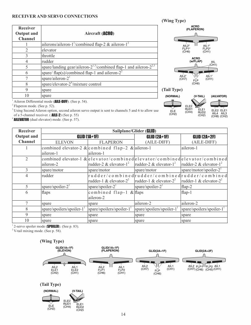
RECEIVER AND SERVO CONNECTIONS
ReceiverOutput and
ChannelAircraft (ACRO)
1 1 2
2 elevator3 throttle4 rudder5 1,3 2,3
6 2
7 1
8 4
9 spare10 spare
1 Aileron Differential mode (AILE-DIFF). (See p. 54).2 Flaperon mode. (See p. 52).3 Using Second Aileron option, second aileron servo output is sent to channels 5 and 6 to allow use of a 5-channel receiver. ( AILE-2) (See p. 55)
4 AILEVATOR (dual elevator) mode. (See p. 57).
ReceiverOutput and
Channel
Sailplane/Glider (GLID)GLID (1A+1F) GLID (2A+1F)
(AILE-DIFF)GLID (2A+2F)(AILE-DIFF)ELEVON FLAPERON
1 combined elevator-2 & aileron-1
c o m b i n e d f l a p - 2 & aileron-1
aileron-1 aileron-1
2 combined elevator-1 & aileron-2 rudder-2 & elevator-12 rudder-2 & elevator-12 rudder-2 & elevator-12
3 1
4 rudderrudder-1 & elevator-22 rudder-1 & elevator-22 rudder-1 & elevator-22
5 1 1 1
6 c o m b i n e d f l a p - 1 & aileron-2
7 spare spare aileron-2 aileron-28 1 1 1 1
9 spare spare spare spare10 spare spare spare spare
1 2-servo spoiler mode (SPOILER). (See p. 83).2 V-tail mixing mode. (See p. 58).
ACRO(FLAPERON)
AIL12
FLP22
(CH1)
AIL22
FLP12
(CH6)
AIL(CH1)
AIL11
(CH1)FLP(CH6)
ACRO(w/FLAP)
AIL21
(CH7)
(Wing Type)
(V-TAIL)
ELE1RUD2(CH2)
ELE2RUD1(CH4)
(NORMAL)
ELE(CH2)
(AILVATOR)
ELE1AIL3
(CH2)
ELE2AIL4
(CH8)
(Tail Type)
AIL1ELE2(CH1)
GLID(1A+1F)(ELEVON)
AIL2ELE1(CH2)
GLID(1A+1F)(FLAPERON)
AIL1FLP2(CH1)
AIL2FLP1(CH6)
AIL1(CH1)
FLP1(CH6)
FLP2(CH5)
AIL2(CH7)
GLID(2A+2F)
AIL1(CH1)
AIL2(CH7)
FLP(CH6)
GLID(2A+1F)
(Wing Type)
(V-TAIL)
ELE1RUD2(CH2)
ELE2RUD1(CH4)
(NORMAL)
ELE(CH2)
(Tail Type)
15
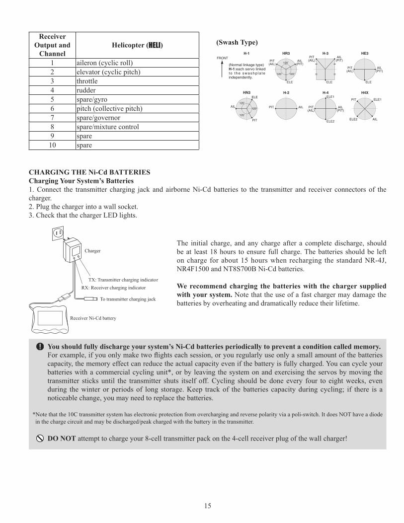
The initial charge, and any charge after a complete discharge, should be at least 18 hours to ensure full charge. The batteries should be left
NR4F1500 and NT8S700B Ni-Cd batteries.
We recommend charging the batteries with the charger supplied with your system. Note that the use of a fast charger may damage the batteries by overheating and dramatically reduce their lifetime.
You should fully discharge your system’s Ni-Cd batteries periodically to prevent a condition called memory.
capacity, the memory effect can reduce the actual capacity even if the battery is fully charged. You can cycle your batteries with a commercial cycling unit*, or by leaving the system on and exercising the servos by moving the transmitter sticks until the transmitter shuts itself off. Cycling should be done every four to eight weeks, even during the winter or periods of long storage. Keep track of the batteries capacity during cycling; if there is a noticeable change, you may need to replace the batteries.
*Note that the 10C transmitter system has electronic protection from overcharging and reverse polarity via a poli-switch. It does NOT have a diode
DO NOT attempt to charge your 8-cell transmitter pack on the 4-cell receiver plug of the wall charger!
CHARGING THE Ni-Cd BATTERIES Charging Your System’s Batteries 1. Connect the transmitter charging jack and airborne Ni-Cd batteries to the transmitter and receiver connectors of the charger. 2. Plug the charger into a wall socket. 3. Check that the charger LED lights.
ReceiverOutput and
ChannelHelicopter (HELI)
1 aileron (cyclic roll)2 elevator (cyclic pitch)3 throttle4 rudder56 pitch (collective pitch)789 spare10 spare
(Swash Type)HR3H-1 H-3
ELE ELE
ELE1
ELE2
120˚
120˚120˚
PIT(AIL)
AIL(PIT)
PIT(AIL)
AIL(PIT)
HN3
120˚
120˚
120˚
ELE
PIT
AIL
HE3
ELE
PIT(AIL)
AIL(PIT)
PIT(AIL)
AIL(PIT)
H-2
PIT
FRONT
AIL
H-4
ELE1
ELE2 AIL
PIT
H4X
(Normal linkage type)H-1:each servo linked to the swashp la te independently.
Charger
TX: Transmitter charging indicatorRX: Receiver charging indicator
To transmitter charging jack
Receiver Ni-Cd battery

16
Adjusting the length of the non-slip control sticks
to remove the rear case of the transmitter. First, remove the battery cover on the rear of the transmitter. Next, unplug the battery wire, and remove the battery and RF module from the transmitter. While you are removing the RF module, pay attention to the location of the pins that plug into the back of the module. Next, using a screwdriver, remove the four screws that hold the transmitter’s rear cover in position, and put them in a safe place. Gently ease off the transmitter’s rear
Using a small Phillips screwdriver, rotate the adjusting screw for each stick for the desired spring tension. The tension increases when the adjusting screw is turned clockwise.
board is on its locating pins, then very carefully reinstall the rear cover being mindful to guide the RF module connector pins through the slot in the case. When the cover is properly in place, reinstall and tighten the four screws. Reinstall the battery, cover and module.
Adjusting Display Contrast:
To adjust the display contrast, from the home menu press and hold the END BUTTON.Turn the DIAL while still holding the END BUTTON:
clockwise to brighten counterclockwise to darken the display
Let go off the DIALand the BUTTON.
You may change the length of the control sticks to make your transmitter more comfortable to hold and operate. To lengthen or shorten your transmitter’s
A counterclockwise. Next, move the locking piece B up or down (to lengthen or shorten). When the length feels comfortable, lock the position by turning locking piece B counterclockwise.
Stick tip A Locking piece B
Stick lever tension adjustment
Mode 2 transmitter with rear cover removed.
Aileron
Elevator
RudderStick Stick
17
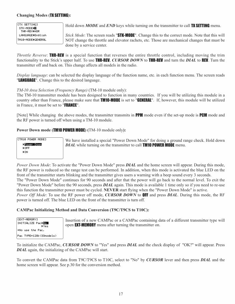
Changing Modes (TX SETTING):
Hold down MODE and END keys while turning on the transmitter to call TX SETTING menu.
Stick Mode: The screen reads "STK-MODE". Change this to the correct mode. Note that this will NOT change the throttle and elevator rachets, etc. Those are mechanical changes that must be done by a service center.
Throttle Reverse: THR-REV is a special function that reverses the entire throttle control, including moving the trim functionality to the Stick’s upper half. To use THR-REV, CURSOR DOWN to THR-REV and turn the DIAL to REV. Turn the transmitter off and back on. This change affects all models in the radio.
Display language: can be selected the display language of the function name, etc. in each function menu. The screen reads "LANGUAGE". Change this to the desired language.
TM-10 Area Selection (Frequency Range) (TM-10 module only):The TM-10 transmitter module has been designed to function in many countries. If you will be utilizing this module in a country other than France, please make sure that TM10-MODE is set to "GENERAL". If, however, this module will be utilized in France, it must be set to "FRANCE".
[Note] While changing the above modes, the transmitter transmits in PPM mode even if the set-up mode is PCM mode and the RF power is turned off when using a TM-10 module.
Power Down mode (TM10 POWER MODE) (TM-10 module only):
We have installed a special "Power Down Mode" for doing a ground range check. Hold down DIAL while turning on the transmitter to call TM10 POWER MODE menu.
Power Down Mode: To activate the "Power Down Mode" press DIAL and the home screen will appear. During this mode, the RF power is reduced so the range test can be performed. In addition, when this mode is activated the blue LED on the front of the transmitter starts blinking and the transmitter gives users a warning with a beep sound every 3 seconds. The "Power Down Mode" continues for 90 seconds and after that the power will go back to the normal level. To exit the "Power Down Mode" before the 90 seconds, press DIAL again. This mode is available 1 time only so if you need to re-use this function the transmitter power must be cycled. NEVERPower Off Mode: To use the RF power off mode, CURSOR DOWN to OFF and press DIAL. During this mode, the RF power is turned off. The blue LED on the front of the transmitter is turn off.
CAMPac Initializing Method and Data Conversion (T9C/T9CS to T10C):
Insertion of a new CAMPac or a CAMPac containing data of a different transmitter type will open EXT-MEMORY menu after turning the transmitter on.
To initialize the CAMPac, CURSOR DOWN to "Yes" and press DIAL and the check display of "OK?" will appear. Press DIAL again, the initializing of the CAMPac will start.
CURSOR lever and then press DIAL and the home screen will appear. See p.30 for the conversion method.

18
RADIO INSTALLATION
Follow these guidelines to properly mount the servos, receiver and battery.
• Make certain the alignment tab on the battery, switch and servo connectors is oriented correctly and “keys” into the corresponding notch in the receiver or connectors before plugging them in. When unplugging connectors, never pull on the wires. Always pull on the plastic connector instead.
• Receiver Antenna (72MHz band): It is normal for the receiver antenna to be longer than the fuselage. DO NOT cut or fold it back on itself. cutting or folding changes the electrical length of the antenna and may reduce range. Secure the
• If your aileron servo (or others) are too far away to plug into the receiver, use an aileron extension cord to extend the length of the servo lead. Additional Futaba extension cords of varying lengths are available from your hobby dealer. Always use an extension of the proper length. Avoid plugging multiple extensions together to attain your desired length. If distance is greater than 18” or multiple or high current draw servos are being used, use Futaba Heavy-Duty servo extensions.
and temperature extremes. For protection, wrap the receiver in foam rubber or other vibration-absorbing materials.It is also a good idea to waterproof the receiver by placing it in a plastic bag and securing the open end of the bag with a rubber band before wrapping it with foam rubber. If you accidentally get moisture or fuel inside the receiver, you may experience intermittent operation or a crash. If in doubt, send the receiver for service.
ServoRubber
grommet ServoRubber
grommet• Always mount the servos with the supplied rubber grommets. Do not over
tighten the screws. No part of the servo casing should contact the mounting
failure.
• Note the small numbers (1, 2, 3, 4) molded into each arm on the Futaba 4-arm servo arms. The numbers indicate how many degrees each arm is “off” from 90 degrees to correct for minute manufacturing deviations from servo to servo.
• To center the servos, connect them to the receiver and turn on the transmitter and receiver. Center the trims on the transmitter, then find the arm that will be perpendicular to the pushrod when placed on the servo.
• After the servos are installed, operate each servo over its full travel and check that the pushrods and servo arms do not bind or contact each other. Also make sure the controls do not require excess force to operate. If there is an objectionable buzzing sound coming from a servo, there is probably too much resistance in the control. Find and correct the problem. Even if there is no servo damage, excess battery drain will result.
• Use the mounting plateon the side of the fuselage opposite the engine exhaust, and where it won’t be inadvertently turned on or off during handling or storage. Be certain the switch moves without restriction and “snaps” from ON to OFF, and that the cutout allows full motion of the switch in both directions.

19
• When you install the switch harness to the helicopter, please use the switch cover. Generally sandwich the frame by switch and switch cover and securely tighten the screws. Different models might require different installations. In that case, please follow the model instruction manual.
Fasten about 5-10cm from the servo outlet so that the lead wire is neat.
Margin in the lead wire.
provide a margin so that the wire sticks out slightly and fasten it at suitable points. In addition, periodically check the wire during daily maintenance.
IMPORTANT: Since the 2.4GHz have different characteristics than that of the conventional 27MHz and 72MHz
Antenna
*Must be kept as straight as possible.
Coaxial cable
R6014FS Receiver
• The R6014FS has two antennas. These antennas have a diversity function to decrease the chance of a receiving error.
• Since the wavelength of the 2.4GHz is much shorter than that of the conventional frequencies 27MHz and 72MHz, it is very susceptible to loss of signal which results in a receiving error. In order to avoid this phenomenon, the R6014FS adopted a diversity antenna system.
• To obtain the best results of the diversity function, please refer to the following instructions;
1. The two antennas must be kept as straight as possible. Otherwise it will reduce the effective range.
2. The two antennas should be placed at 90 degrees to each other.
away from each other as much as possible. Larger models can have large metal objects that can attenuate the RF signal.In this case the antennas should be placed at both sides of the model. Then the best
3. The antennas must be kept away from conductive materials, such as metal and carbon by at least a half inch. The coaxial part of the antennas does not need to follow these guidelines, but do not bend it in a small radius.
4. Keep the antennas away from the motor, ESC, and other noise sources as much as possible.
Antenna Antenna
*The two antennas should be placed at 90 degrees to each other. *The main purpose of the photo demonstrates how the antenna should be placed.
protect it from vibration.

20
• The receiver contains precision electronic parts. It is the most delicate radio component on-board the model and should
vibration-absorbing material. If appropriate, waterproof the receiver by placing it in a plastic bag and closing the open end with a rubber band before wrapping it in foam. If moisture enters the receiver, intermittent operation or a failure may result. Wrapping the receiver in a plastic bag also protects it from fuel and exhaust residue which, in some models, can work its way into the fuselage.
Product Advisory — R6014FS ReceiverWhereas many previous receivers offered a signal output of 3.0 Volts, the latest generation of ICs has been designed to operate at lower voltages in order to increase their operational speeds. The R6014FS receiver utilizes such an IC and, as such, the nominal signal output voltage of the R6014FS receiver is 2.7 Volts.
While this variance in the output voltage will not affect most equipment in use today, it has been brought to our attention that some manufacturers’ products are not capable of operation with the lower signal voltage. That is, they will not operate below 3.0 Volts. Some examples of what we have had reported thus far include sequencers, cut-off valves, older servo designs and some recent non-Futaba digital servos.
they might not appear to initially. One such device functions perfectly on the ground and during a range check, yet when the operational temperature reaches 50°C (122°F), the device actually requires 2.8 Volts in order to function properly. As such, the servos will cease to operate properly.
Many manufacturers are updating or refining their products to ensure compatibility with the lower operational voltages. If you have any questions about the operation of such peripheral items we strongly suggest that you contact the manufacturer directly.
If you have already purchased items which can not operate below 3.0 Volts, we suggest that you either replace the item with an updated version or utilize a device to increase the voltage accordingly. There are a number of readily available devices that may be used to increase the voltage such as ElectroDynamics’
products, Smart-Fly’s Power Expander and Powersystem, etc.
Link Procedure (TM-10 module/R6014FS receiver only):Each transmitter has an individually assigned, unique ID code. In order to start operation, the receiver must be linked with the ID code of the transmitter with which it is being paired. Once the link is made, the ID code is stored in the receiver and no further linking is necessary unless the receiver is to be used with another transmitter. When you purchase another R6014FS, this procedure is necessary; otherwise the receiver will not work.
1. Place the transmitter and the receiver close to each other within one (1) meter. 2. Turn on the transmitter. 3. Check the LED that is placed on the front side of the transmitter to see if the RF signal is active. When the blue LED is
ON solid, the RF signal is being sent. 4. Turn on the receiver. 5. Press down the Easy Link(ID SET) switch for more than one second, and release the switch. The receiver starts the
linking operation.
now operate by your transmitter. Please refer to the table below for the LED status of the receiver's condition.
No signal reception Red : On Receiving signals Green: On Receiving signals, but ID is unmatched. Green: Blink Unrecoverable failure (EEPROM, etc.) Red and Green turn on alternately.
21
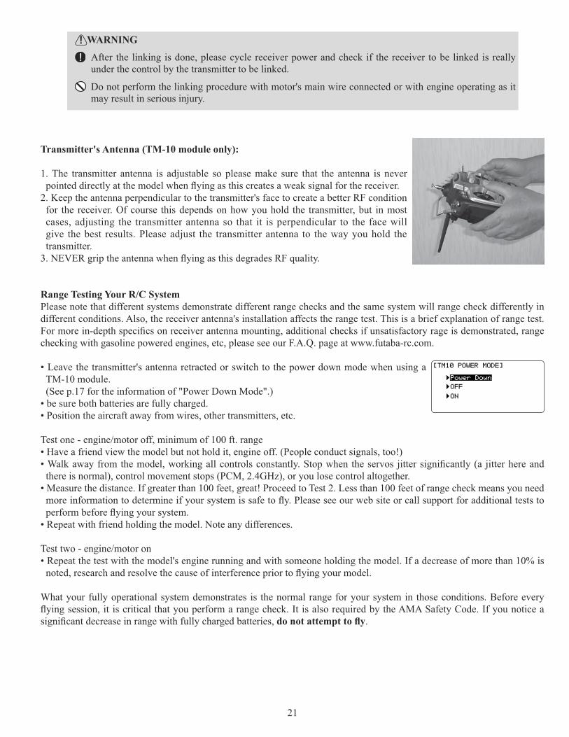
1. The transmitter antenna is adjustable so please make sure that the antenna is never
2. Keep the antenna perpendicular to the transmitter's face to create a better RF condition for the receiver. Of course this depends on how you hold the transmitter, but in most cases, adjusting the transmitter antenna so that it is perpendicular to the face will give the best results. Please adjust the transmitter antenna to the way you hold the transmitter.
Range Testing Your R/C System Please note that different systems demonstrate different range checks and the same system will range check differently in different conditions. Also, the receiver antenna's installation affects the range test. This is a brief explanation of range test.
checking with gasoline powered engines, etc, please see our F.A.Q. page at www.futaba-rc.com.
• Leave the transmitter's antenna retracted or switch to the power down mode when using a TM-10 module. (See p.17 for the information of "Power Down Mode".)
• be sure both batteries are fully charged. • Position the aircraft away from wires, other transmitters, etc.
• Have a friend view the model but not hold it, engine off. (People conduct signals, too!)
there is normal), control movement stops (PCM, 2.4GHz), or you lose control altogether. • Measure the distance. If greater than 100 feet, great! Proceed to Test 2. Less than 100 feet of range check means you need
• Repeat with friend holding the model. Note any differences.
• Repeat the test with the model's engine running and with someone holding the model. If a decrease of more than 10% is
What your fully operational system demonstrates is the normal range for your system in those conditions. Before every
.
WARNING
After the linking is done, please cycle receiver power and check if the receiver to be linked is really under the control by the transmitter to be linked.
Do not perform the linking procedure with motor's main wire connected or with engine operating as it may result in serious injury.

22
72 MHz bandCh. MHz Ch. MHz11 72.010 36 72.51012 72.030 37 72.53013 72.050 38 72.55014 72.070 39 72.57015 72.090 40 72.59016 72.110 41 72.61017 72.130 42 72.63018 72.150 43 72.65019 72.170 44 72.67020 72.190 45 72.69021 72.210 46 72.71022 72.230 47 72.73023 72.250 48 72.75024 72.270 49 72.77025 72.290 50 72.79026 72.310 51 72.81027 72.330 52 72.83028 72.350 53 72.85029 72.370 54 72.87030 72.390 55 72.89031 72.410 56 72.91032 72.430 57 72.93033 72.450 58 72.95034 72.470 59 72.97035 72.490 60 72.990
50 MHz Band (Amateur Radio Operator “HAM” license required)
Ch. MHz Ch. MHz00 50.800 01 50.82002 50.840 03 50.86004 50.880 05 50.90006 50.920 07 50.94008 50.960 09 50.980
It is very important that you display your transmitting channel number at all times. To install your flag, peel off the channel number’s backing sheet, and carefully stick the numbers to both sides of the number holder. Now you can snap the number holder

23
TRANSMITTER DISPLAYS & BUTTONS
leading to an immediate crash.
MODE BUTTON: (key)Press and hold MODE BUTTON for one second to open programming menus. Press N MODE BUTTON to switch Nbetween BASIC and ADVANCE menus. HELI only: Press MODE BUTTON to scroll between conditions in certainNfunctions.
END BUTTON: (key)Press END BUTTON to return to previous screen. Closes functions back to menus, closes menus to start-up screen.
CURSOR LEVER:Control CURSOR LEVERfunction.Press CURSOR LEVER BASIC or ADVANCE menu or a function.
Turn DIAL:Turn DIAL clockwise or counterclockwise to scroll through choices within an option of a function (for example, to
Press DIAL:Press DIAL to select the actual function you wish to edit from the menu.Press DIALmemory, copy one model memory over another, trim reset, store channel position in FailSafe, change model type, reset entire model. System will ask if you are sure. Press DIAL again to accept change.
PUSH
Rudder trimdisplay
Aileron trimdisplay
Elevator/Throttle trimdisplay
Modulation indicator(PCM1024/PPM FM)
(2.4G-7CH/10CH)
16/64/128: CAMPac display (10C data)9C: CAMPac display (9C/9CS data)
Batteryvoltage
Timers
Throttle/Elevator trimdisplay
Model numberand name
Dial
CURSOR lever
ENDkey
MODEkey
Total timer display <TIMER>Shows the cumulated ON time. (hours:minutes)Up/down timer display <ST1.ST2>(minutes:seconds)Model timer display <MDL>Shows the cumulated ON time for each model.(hours:minutes)
MIX: Mixer Alert
Resetting timers:Select the desired timer with CURSOR lever. The timer display flashes. To reset the timer, press Dial for one second.

24
WARNING & ERROR DISPLAYS An alarm or error indication may appear on the display of your transmitter for several reasons, including when the transmitter power switch is turned on, when the battery voltage is low, and several others. Each display has a unique soundassociated with it, as described below.
MODEL SELECTION ERROR: Warning sound: 5 beeps (repeated 3 times)The MODEL SELECTION warning is displayed when the transmitter attempts to load a model memory from a memorymodule (optional CAMPac) that is not currently plugged into the transmitter. When this occurs, model No. 01 is automatically loaded.
Reinsert the memory module, and recall the desired setup using the model select function.
LOW BATTERY ERROR: Warning sound: Continuous beep until transmitter is powered off.The LOW BATTERY warning is displayed when the transmitter battery voltage drops below 8.5V.
Land your model as soon as possible before loss of control due to a dead battery.
MIXER ALERT WARNING: Warning sound: 5 Beeps (repeated until problem resolved or overridden)
The MIXER ALERT warning is displayed to alert you whenever you turn on the transmitter with any of the mixing switches active. This warning will disappear when the offending switch or control is deactivated. Switches for which warnings will be issued at power-up are listed below:
ACRO:Throttle cut, idle-down, snap roll, airbrake GLID HELI:Throttle cut, throttle hold, idle-up
If turning a switch OFF does not stop the mixing warning: When the warning does not stop even when the mixing switchindicated by the warning display on the screen is turned off, the functions described previously probably use the sameswitch and the OFF direction setting is reversed. In short, one of the mixings described above is not in the OFF state. In this case, reset the warning display by pressing CURSOR LEVER. Then change one of the switch settings of the mixings duplicated at one switch.
BACKUP ERROR: Warning sound: 4 beeps (repeated continuously)The BACKUP ERROR warning occurs when the transmitter memory is lost for any reason. If this occurs, all of the data will be reset when the power is turned on again.[Note] At this warning display, the transmitter transmits in PPM mode even if the set-up mode is PCM mode.
Do not fly when this message is displayed: all programming has been erased and is not available. Return your transmitter to Futaba for service.
MEMORY MODULE INITIALIZE DISPLAYThis warning appears when an (optional) CAMPacMODE BUTTON is pressed, initialization of the module begins, after which the memory module can be used. Once the module is initialized, the display will not appear again.
The 10C CANNOT convert data from other radio types (i.e. 8U, 9Z). Installation of a CAMPac with data from another radio type will result in reinitialization of the CAMPac and loss of all data.
RF MODULE WARNING: Warning sound: A single long beep. The single beep lets you know that the RF module has been removed from the transmitter, or is not being read properly. The green RF light also goes out.

25
AIRCRAFT (ACRO) MENU FUNCTIONS
Please note that all BASIC menu functions are the same for airplanes (ACRO), sailplanes (GLID), and helicopters (HELI). The glider BASIC menu includes MOTOR CUT that is discussed in the Glider section and does not include IDLE-DOWN or THR-CUT; the helicopter BASIC
AIRPLANE (ACRO) FUNCTIONS ................................ 25Map of Functions ........................................................ 26Quick Guide to Setting up a 4-channel Airplane ...... 27
ACRO BASIC MENU FUNCTIONS ................................ 30MODEL Submenu: MODEL SELECT, COPY, NAME .......... 30 PARAMETER Submenu: RESET, TYPE, MODUL, ATL, AILE-2,CONTRAST, BACK-LIGHT, HOME-DISP, USER NAME, LOGIC SW ............................................................................. 33Servo REVERSE ........................................................... 38END POINT .................................................................. 39Idle Management: IDLE DOWN and THR-CUT .............. 40
D/R, EXP) .......... 42TIMER Submenu.......................................................... 45Auxiliary Channel assignments and CH9 reverse (AUX-CH) ............................................................................. 46TRAINER ..................................................................... 47TRIM and SUB-TRIM ................................................... 48SERVO Display ........................................................... 49Fail Safe and Battery FailSafe (F/S) ......................... 50
ACRO ADVANCE MENU FUNCTIONS ........................... 51Wing types ................................................................ 51FLAPERON ................................................................... 52FLAP TRIM .................................................................. 53Aileron Differential (AILE-DIFF) ................................. 54Using a 5-channel receiver: AILE-2 ............................ 55ELEVON (see tail types) ............................................... 56Tail types ................................................................... 56ELEVON ....................................................................... 56Twin Elevator Servos (AILEVATOR) ............................ 57V-TAIL ......................................................................... 58SNAP ROLL .................................................................. 59
..................................... 61ELEV-FLAP .................................................................... 62AIRBRAKE BUTTERFLY (crow) ..................................... 63THROTTLE-NEEDLE ........................................................ 65THROTTLE DELAY ......................................................... 66THROTTLE CURVE ........................................................ 67Linear, Prog. mixes 1-4 ............................................. 68Curve, Prog. mixes 5-8 ............................................. 71GYA gyro mixing (GYRO SENSE) ............................... 73

26
MAP OF ACRO BASIC FUNCTIONS
ACRO Basic Menu
( for one second)
(Startup screen)
(Basic Menu 1/2)
To return to the Startup screen, press the End key.
(Basic Menu 2/2)
To enter the Basic Menu, press the Mode key for one second.
Press Mode key to toggle back and forth between BASIC and ADVANCE menus.
Press Cursor lever to page up and down through the 2 pages of screens in each menu. Note that all functions which have more than one page have a <1/2> indicator in the upper right hand corner to indicate page 1 of 2 or page 2 of 2.
Use Cursor lever to highlight function in Menu screen. Then press the Dial to choose that function.
Mode Select
End Selection
Cursor Lever(Down/Up/Left/Right)
Dial Right or Left
Press Dial
Switch Up
Switch at Center
Switch Down
Stick Up
Stick Right
Stick Down
Stick LeftTurn Knob Right
Turn Knob LeftDial Left
Dial Right
Press Cursor Lever
C

27
A QUICK GUIDE: GETTING STARTED WITH A BASIC 4-CHANNEL AIRCRAFT
This guide is intended to help you get acquainted with the radio, to give you a jump start on using your new radio, and to give you some ideas and direction in how to do even more than you may have already considered. It follows our basic format of all programming pages: a big picture overview of what we accomplish; a “by name” description of what we're doing to help acquaint you with the radio; then a step-by-step instruction to leave out the mystery when setting up your model.For additional details on each function, see that function's section in this manual. The page numbers are indicated in the goals column as a convenience to you.
See p.26 for a legend of symbols used.
GOALS of EXAMPLE STEPS INPUTS for EXAMPLEPrepare your aircraft. Install all servos, switches, receivers per your model's instructions. Turn on
transmitter then receiver; adjust all linkages so surfaces are nearly centered. Mechanically adjust all linkages as close as possible to proper control throws. Check servo direction. Make notes now of what you will need to change during programming.
Name the model. P. 32.
[Note that you do not need to do anything to "save” or store this data. Only critical changes such as a MODELRESET require additional keystrokes to accept the change.]
Open the BASIC menu, then open the MODEL submenu.
Turn on the transmitter.
for 1 second. (If ADVANCE, again.)
C as needed to highlight MODEL.
to choose MODEL.Go to MODEL NAME. C to NAME.
(First character of model's name is highlighted.)
Input aircraft's name. Close the MODEL submenu. When proper character is displayed,
C to move to next character.Repeat as needed.
to return to BASIC menu.Reverse servos as needed for proper control operation. P. 38.
In the B A S I C menu, open (servo) REVERSE.
C to REVERSE.
to choose REVERSE.Choose desired servo and reverse its direction of travel. (Ex: reversing rudder servo.)
C to CH4: RUDD.
so REV is highlighted.
Repeat as needed. Adjust Travels as needed to match model's recommended throws (usually listed as high rates). P. 39.
From BASIC menu, choose END POINT. C to END POINT.
to choose END POINT.Adjust the servo's end points. (Ex: throttle servo) Close the function.
C to THROTTLE.
THROTTLE STICK.
until carb barrel closes as desired.
THROTTLE STICK.
until throttle arm just opens carb fully at full THROTTLE STICK.
Repeat for each channel as needed.

28
With digital trims you don’t shut the engine off with THROTTLE TRIM. Let's set up IDLE-DOWN and "throttle cut" (THR-CUT)now.
GOALS of EXAMPLE STEPS INPUTS for EXAMPLESet up IDLE-DOWN.P. 40.
IDLE-DOWN slows the engine's idle for landings, sitting on the runway, and maneuvers such as spins. The normal (higher idle) setting (when IDLE-DOWN is off) is for engine starting, taxi, and most
From the BASIC menu, choose IDLE-DOWN.
C to IDLE-DOWN.
to choose IDLE-DOWN.Activate and adjust IDLE-DOWN. C to MIX. to OFF.
C to center position. Screen now reads ON.
C to RATE.
to increase rate until engine idles reliably but low enough to sit still.
Optional: change switch command from C center-and-down to any other switch.
(Not needed in this example.)
Close the Function.
THR-CUT shuts the engine off completely
P. 41.
(NOTE: DO NOT assign IDLE-DOWN and THR-CUT to both positions of a 2position switch. See IDLE-DOWN for details.)
From the BASIC menu, choose THR-CUT. C to THR-CUT.
to choose THR-CUT.Activate, assign SWITCH and adjust. Close the function.
C to MIX. to OFF.C to SW. to C.C to POSI. to DOWN.C to RATE. C to down position.
THROTTLE STICK.
u n t i l t h r o t t l e b a r r e l c l o s e s completely.
(D/R,EXP).P. 42.
(Note that in the middle of the left side of the screen is the name of the channel AND the switch position you are adjusting. Two or even THREE rates may be set per channel by simply choos ing the des ired swi tch and programming percentages with the switch in each of its 2 or 3 positions.)
From the BASIC menu, choose D/R,EXP. C to D/R,EXP.
to choose D/R,EXP.Choose the desired control, and set the first (Ex: high) rate throws and exponential.
A to up position.C to CH:.
to choose CH>2 (elevator).[note the screen reads ELEV (UP)]
C to D/R.
ELEVATOR STICK.
to set desired “UP” percentage.
ELEVATOR STICK.
as needed to adjust “DOWN” percentage (normally set the same as down.)
C to EXP.
ELEVATOR STICK. to set.
ELEVATOR STICK. to set.

29
GOALS of EXAMPLE STEPS INPUTS for EXAMPLE Set the second (low) rate throws and exponential.
A to down position.C to D/R.
Repeat steps above to set low rate.Optional: change dual rate switch assignment. Ex: elevator to switch G (10CA) or E (10CH) with 3 positions.
C to SW. to G or E.
G or E to center position.Repeat steps above to set 3rd rate.
Where next? (Other functions you may wish to set up for your model.) TRAINER p. 47.
Elevator-to-flap, Rudder-to-aileron, flap-to-elevator, and other programmable mixes p. 68.Retractable Gear, Flaps on a Switch, Smoke systems, kill switches, and other auxiliary channel setups. p. 46.

30
MODEL submenu: includes three functions that manage model memory: MODEL SELECT, MODELCOPY and MODELNAME. Since these functions are all related, and are all basic features used with most models, they are together in the MODEL submenu of the BASIC menu.
NOTE: When you choose a new model in the MODEL SELECT function, if the new model is set to the other modulation, you must cycle the transmitter power to change
screen to remind you. You are still transmitting on the other modulation until you affect this change.
GOAL: STEPS: INPUTS:Select Model #3.
N O T E : T h i s i s o n e o f s e v e r a l functions for which the radio requires
Open BASIC menu, then open MODELsubmenu.
for 1 second. (If ADVANCE, again.)
C if required to MODEL.Choose Model #3. to 3.
for 1 second.
Are you sure? displays.Close.
Confirm proper modulation of new model memory.
If PPM, PCM or 2.4G
modulation.Where next? NAME the model: see p. 32.
Change MODEL TYPE (aircraft, heli, glider): see p. 34.Change modulation [FM (PPM PCM or 2.4G-10CH 7CH]: see p. 35.Utilize servo REVERSE: see p. 38.Adjust END POINTs: see p. 39.Set up IDLE-DOWN and THR-CUT for throttle management: see p. 40, 41.
MODEL SELECT: This function selects which of the 15 model memories in the CAMPac-
number. (Each model memory may be a different model type from the other memories.)
T9C/T9CS CAMPac data conversionAlthough a CAMPaccannot be used calling directly, it is possible to use it by the following method, copying to the model memories of a T10C transmitter. When using the CAMPac, it will be displayed, for example as "01<-Pac 01." Press DIAL for 1 second in this state and the check display of "Are you sure?" will appear. Press DIAL again, the data of CAMPac will be copied to model
number"01" of the T10C transmitter. As for the data of a function added by T10C, an initial value is set up at this time.
In addition, refer to p.17 for the initializing method of the CAMPac.
Note: If you are using the optional CAMPac-16K, your choices in MODEL SELECT and MODEL COPY will include 16-19, which are the model memories in the CAMPac. You do not have to COPY from the CAMPac to the transmitter prior to working with that model
31
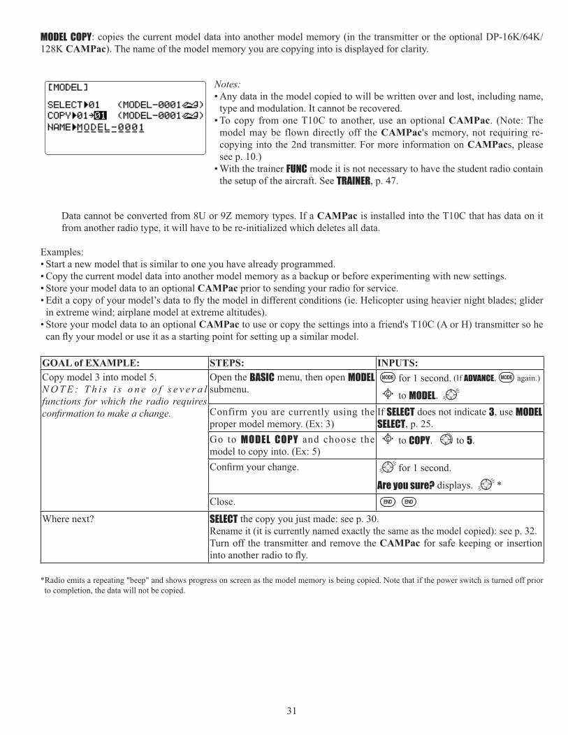
MODEL COPY128K CAMPac). The name of the model memory you are copying into is displayed for clarity.
Notes:• Any data in the model copied to will be written over and lost, including name,
type and modulation. It cannot be recovered. • To copy from one T10C to another, use an optional CAMPac. (Note: The
model may be flown directly off the CAMPac's memory, not requiring re-copying into the 2nd transmitter. For more information on CAMPacs, please see p. 10.)
• With the trainer FUNC mode it is not necessary to have the student radio contain the setup of the aircraft. See TRAINER, p. 47.
Data cannot be converted from 8U or 9Z memory types. If a CAMPac is installed into the T10C that has data on it from another radio type, it will have to be re-initialized which deletes all data.
Examples:• Start a new model that is similar to one you have already programmed. • Copy the current model data into another model memory as a backup or before experimenting with new settings. • Store your model data to an optional CAMPac prior to sending your radio for service.
in extreme wind; airplane model at extreme altitudes). • Store your model data to an optional CAMPac to use or copy the settings into a friend's T10C (A or H) transmitter so he
GOAL of EXAMPLE: STEPS: INPUTS:Copy model 3 into model 5. N O T E : T h i s i s o n e o f s e v e r a l functions for which the radio requires
Open the BASIC menu, then open MODELsubmenu.
for 1 second. (If ADVANCE, again.)
C to MODEL.Confirm you are currently using the proper model memory. (Ex: 3)
If SELECT does not indicate 3, use MODELSELECT, p. 25.
Go to MODEL COPY and choose the model to copy into. (Ex: 5)
C to COPY. to 5.
for 1 second.
Are you sure? displays. *Close.
Where next? SELECT the copy you just made: see p. 30. Rename it (it is currently named exactly the same as the model copied): see p. 32.Turn off the transmitter and remove the CAMPac for safe keeping or insertion
*Radio emits a repeating "beep" and shows progress on screen as the model memory is being copied. Note that if the power switch is turned off prior to completion, the data will not be copied.

32
MODEL NAME: assigns a name to the current model memory. By giving each model a name that is immediately recognizable,
a crash.
Adjustability and values: • Up to 10 characters long. • Each character may be a letter, number, blank, or a symbol. • The default names assigned by the factory are in MODEL-xxxx format
(MODEL-0001
NOTE: When you COPY one model memory over another, everything is copied, including the model's name. Similarly, if you change MODEL TYPE or do a MODEL RESET, the entire memory is reset, including MODEL NAMEwant to do after you COPY a model, change its type, or start from scratch, is rename the new copy to avoid confusion. If using multiple frequency modules to be able to transmit on multiple channels, we recommend using the last 2 characters to indicate the receiver's channel for clarity. For more information on frequency transmission, see p. 8.
GOAL of EXAMPLE: STEPS: INPUTS:Name model 3 “Cap-232_” (where the underline represents a blank space.)
Open MODEL submenu. for 1 second. (If ADVANCE, again.)
C to MODEL.Confirm you are currently using the proper model memory. (Ex: 3)
If SELECT does not indicate 3,
perform MODEL SELECT, p. 25.Go to N A M E and change the f i r s t character. (Ex: M to C)
C to M to C.
Choose the next character to change. C
Repeat the prior steps to complete naming the model.
to a (note: lower case is available)
Repeat.Close.
Where next? Change the MODEL TYPE to glider or helicopter: see p. 34.Change modulation [FM (PPM PCM or 2.4G-10CH 7CH]: see p. 35.Utilize servo REVERSE: see p. 38.Adjust servo travel with END POINT: see p. 39.
D/R,EXP): see p. 42.

33
PARAMETER submenu: sets those parameters you would likely set once, and then not disturb again. Once you have selected the correct model you wish to work with, the next step is setting up the proper parameters for this
• What is the model's type? • What type is the receiver’s modulation [FM (PPM PCM or 2.4G-10CH 7CH]?• Does the model have a normal throttle on channel 3 or do you need full range
trim on channel 3 (ATL)?• If you are utilizing either of the twin aileron functions, do you need to tell the
radio your receiver is only 5 channels?
First it is important to clear out any old settings in the memory from prior use, using the MODEL RESET.MODEL RESET: completely resets all data in the individual model you have currently selected. Don't worry - there is no way you can accidentally delete all models in your radio with this function. Only a service center can completely reset your radio's entire memory at once. To delete each model in your radio's memory (for example when selling), you must SELECTeach model, reset that memory, then go SELECT the next memory, etc.
Note that when you COPY one model memory into another or change the model's type, you need not delete all existing data COPY completely overwrites anything in the existing model memory, including MODEL NAME.
The MODEL TYPE function overwrites all data except name and MODUL.
GOAL of EXAMPLE: STEPS: INPUTS:Reset model memory 1.
N O T E : T h i s i s o n e o f s e v e r a l functions for which the radio requires
Confirm you are currently using the proper model memory. (Ex: 1)
On home screen, check model name and number on top left. If it is not correct, use MODEL SELECT, p. 30.
Open PARAMETER submenu. for 1 second. (If ADVANCE, again.)
to 2nd page of menu. C to PARAMETER.
Reset the Memory. for one second.
Are you sure? displays. *Close.
Where next? Now that the memory is reset, name has returned to the default (Ex: MODEL-0001).NAME the model: p. 32.COPY a different model into this memory: p. 31. SELECT a different model to edit or delete: p. 30. Change the MODEL TYPE to glider or helicopter: see p. 34. Change the receiver modulation [FM (PPM PCM or 2.4G-10CH 7CH]: see p. 35. Utilize servo REVERSE: see p. 38. Adjust servo travel with END POINT: see p. 39.
D/R,EXP): see p. 42.*Radio emits a repeating “beep” and shows progress on screen as the model memory is being reset. Note that if the power switch is turned off prior to completion, the data will not be reset.
34
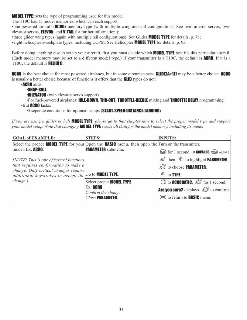
MODEL TYPE: sets the type of programming used for this model.The T10C has 15 model memories, which can each support:•one powered aircraft (ACROelevator servos, ELEVON, and V-TAIL for further information.);
MODEL TYPE for details, p. 78; •eight helicopter swashplate types, including CCPM. See Helicopter MODEL TYPE for details, p. 93.
MODEL TYPE(Each model memory may be set to a different model type.) If your transmitter is a T10C, the default is ACRO. If it is a T10C, the default is HELI(H1).
ACRO is the best choice for most powered airplanes, but in some circumstances, GLID(2A+1F) may be a better choice. ACROis usually a better choice because of functions it offers that the GLID types do not:
•ACRO adds: •SNAP-ROLL•AILEVATOR (twin elevator servo support) •For fuel-powered airplanes: IDLE-DOWN, THR-CUT, THROTTLE-NEEDLE mixing and THROTTLE DELAY programming.
•But ACRO lacks: •5 seperate conditions for optional setups (START SPEED DISTANCE LANDING)
If you are using a glider or heli MODEL TYPE, please go to that chapter now to select the proper model type and support your model setup. Note that changing MODEL TYPE resets all data for the model memory, including its name.
GOAL of EXAMPLE: STEPS: INPUTS:Select the proper MODEL TYPE for your model. Ex: ACRO.
[NOTE: This is one of several functions that requires confirmation to make a change. Only critical changes require additional keystrokes to accept the change.]
Open the BASIC menu, then open the PARAMETER submenu.
Turn on the transmitter.
for 1 second. (If ADVANCE, again.)
then C to highlight PARAMETER.
to choose PARAMETER.Go to MODEL TYPE. C to TYPE.Select proper MODEL TYPE.Ex: ACRO.
Close PARAMETER.
to ACROBATIC. for 1 second.
Are you sure? displays.
to return to BASIC menu.

35
Modulation select (MODUL): sets the type of modulation transmitted.The modulation of your receiver will determine whether you utilize FM (PPM PCM or 2.4G-10CH 7CH setting in MODULduring transmission. Note that you have to turn your transmitter off and back on before a modulation change becomes effective. If you choose PCM or 2.4G-10CH 7CH, be sure you understand and set the FailSafe (F/S ) settings as you intended (see p. 50). When utilize PPM or PCM setting, use the TP-FM module. When you utilize 2.4G-10CH 7CH setting, use the TM-10 2.4GHz module.
PCM = Pulse Code Modulation PPM = Pulse Position Modulation (also called FM)2.4G-10CH 7CH = FASST-2.4GHz system (10CH 7CH mode)
Adjustability:• PCM setting for all Futaba PCM1024 receivers, regardless of number of
• PPM setting for all Futaba compatible (negative shift) FM receivers, regardless of number of channels (ie. R127DF, R123F, R138DF, R148DF).
• Not compatible with PCM512 receivers such as the R128DP and R105iP. • Not compatible with other brands of PCM receiver, or positive shift FM
• You do not need a different module in the radio to transmit in PCM . For more information on PCM, please see our website.
• 2.4G-10CH setting for all Futaba FASST-2.4G Multi-ch mode receivers,
• 2.4G-7CH setting for all Futaba FASST-2.4G 7ch mode receivers, regardless of
NOTE: When you change models in MODEL SELECT, if the new model is set to the other modulation type,
to remind you until you do so. See p. 30, MODEL SELECT, for details.
GOAL of EXAMPLE: STEPS: INPUTS:Change model 1 from FM (PPM) to PCM.
Confirm you are currently using the proper model memory (Ex: 1)
On home screen, check model name and number on top left and the modulation on top right. If it is not the correct model, use MODEL SELECT, p. 30.
O p e n B A S I C m e n u , t h e n o p e n PARAMETER submenu.
for 1 second. (If ADVANCE, again.)
to 2nd page of menu. C to PARAMETER.
Go to MODUL and change setting. C to MODUL. to PCM . cycle power
Close menu and cycle power.
POWER OFF. POWER ON.Where next? Now that the model is in the proper modulation, the T10C should communicate
receiver. [Futaba receivers ending in F use PPM(ex: R148DF), ending in P use PCM (ex: R149DP)]. Change MODEL TYPESet F/S settings for when PCM or 2.4G receiver sees interference: see p. 50. Utilize servo REVERSE: see p. 38. Adjust servo travel with END POINT: see p. 39.
D/R,EXP): see p. 42.

36
Adjustable travel limit (ATL): makes the channel 3 TRIM LEVER (THROTTLE TRIM) effective only at low throttle, disabling the trim at high throttle. This prevents pushrod jamming due to idling trim changes. This function defaults to ON.If you are not using channel 3 for throttle, you may want trim operation the same as on all other channels. To do so, set ATLto OFF. If you need the ATL to be effective at the top of the stick instead of the bottom, reverse the THR-REV setting. Note that this affects all models in the radio, not just the model you are currently editing. See servo REVERSE, p. 38.
GOAL of EXAMPLE: STEPS: INPUTS:Change ATL from ON to OFF for battling robot, tank, airbrake and other channel 3 uses.
O p e n B A S I C m e n u , t h e n o p e n PARAMETER submenu.
for 1 second. (If ADVANCE, again.)
to 2nd page of menu.C to PARAMETER.
Go to ATL and Change. (Ex: to OFF) C to ATL. to OFF.Close.
Where next? Set up ELEVONSet up IDLE-DOWN and THR-CUT to adjust channel 3 servo at low-stick: see p. 40.
Utilize servo REVERSE: see p. 38.Adjust servo travel with END POINT: see p. 39.
D/R,EXP): see p. 42.
Second aileron (AILE-2) (ACRO GLID 1A+1F GLID 2A+1F only): changes the default choice for dual aileron servos from channels 6 (FLAPERON) to channels 5 and 6, or 7(AIL-DIF ) to channels 5 and 7. This allows you to utilize these 2 great functions while utilizing a 5-channel receiver. NOTE: Changing AILE-2 only tells the system which servos to utilize if FLAPERON or AIL-DIF is activated. You still must activate that function and complete its setup. For details on twin aileron servos, including using AILE-2, see p. 55.
LCD screen adjustment (CONTRAST BACK-LIGHT):
Adjustability:The following LCD screen adustments are possible. • Contrast adjustment• Backlighting brightness adjustment
CONTRAST: set a LCD contrast from +10(dark) to -10(bright). Also it can be set from the home screen. See Adjusting Display Contrast, p.16.BACK-LIGHT MAXkeys. Setting range: OFF(0) to 20(bright).BACK-LIGHT MIN MAX setting.
GOAL of EXAMPLE: STEPS: INPUTS:Change CONTRAST from 0 to +2. O p e n B A S I C m e n u , t h e n o p e n
PARAMETER submenu.for 1 second. (If ADVANCE, again.)
C to PARAMETER.Go to CONTRAST and change setting. (Ex: +2)
C to CONTRAST.
to +2.Close.
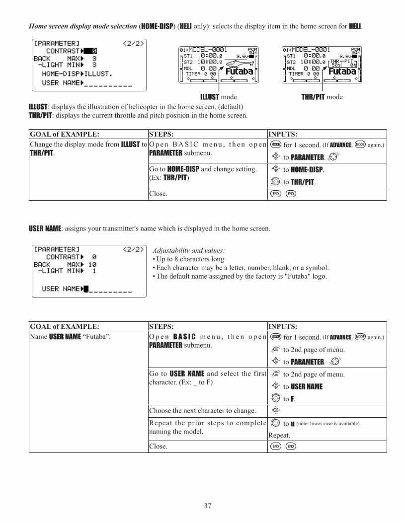
37
Home screen display mode selection (HOME-DISP) (HELI only): selects the display item in the home screen for HELI.
ILLUST: displays the illustration of helicopter in the home screen. (default)THR/PIT: displays the current throttle and pitch position in the home screen.
GOAL of EXAMPLE: STEPS: INPUTS:Change the display mode from ILLUST to THR/PIT.
O p e n B A S I C m e n u , t h e n o p e n PARAMETER submenu.
for 1 second. (If ADVANCE, again.)
C to PARAMETER.Go to HOME-DISP and change setting. (Ex: THR/PIT)
C to HOME-DISP.
to THR/PIT.Close.
USER NAME: assigns your transmitter's name which is displayed in the home screen.
Adjustability and values: • Up to 8 characters long. • Each character may be a letter, number, blank, or a symbol. • The default name assigned by the factory is "Futaba" logo.
GOAL of EXAMPLE: STEPS: INPUTS:Name USER NAME “Futaba”. O p e n B A S I C m e n u , t h e n o p e n
PARAMETER submenu.for 1 second. (If ADVANCE, again.)
to 2nd page of menu.C to PARAMETER.
Go to USER NAME and select the first character. (Ex: _ to F)
to 2nd page of menu.C to USER NAME
to F.Choose the next character to change. C
Repeat the prior steps to complete naming the model.
to u (note: lower case is available)
Repeat.Close.
THR/PIT modeILLUST mode

38
Servo reversing (REVERSE): changes the direction an individual servo responds to a CONTROL STICK motion. [Since channel 9 and 10 are switch only (and only available with a PCM or 2.4G-10CH mode), its servo REVERSE is in the AUX-CH control screen with its switch assignment. See p. 46.] For CCPM helicopters, be sure to read the section on SWASH AFR (p. 95) before reversing any servos.
Except with CCPM helicopters, always complete your servo reversing prior to any other programming. If you use pre-built ACRO GLID functions that control multiple servos, such as FLAPERON or V-TAIL, it may be confusing to tell whether the servo needs to be reversed or a setting in the function needs to be reversed. See the instructions for each specialized function for further details.
Always check servo direction prior to every flight as an additional
NOTE: THR-REV is a special function that reverses the entire throttle control, including moving the trim functionality to the Stick’s upper half. To use THR-REV, turn off the transmitter, hold down the MODE and END keys, turn on. CURSORDOWN to THR-REV and turn the DIAL to REV. Turn the transmitter off and back on. This change affects all models in the radio.
GOAL of EXAMPLE: STEPS: INPUTS:Reverse the direction of the elevator servo.
Open REVERSE function. for 1 second. (If ADVANCE, again.)
C to REVERSE.C h o o s e p r o p e r c h a n n e l a n d s e t direction. (Ex: ELE REV)
C to ELE.
to REV. for 1 second.Close.
Where next? Adjust servo travel with END POINT: see p. 39.D/R,EXP): see p. 42.
Set up trainer functions: see p. 47.
Logic switch selection (LOGIC SW): The various functions in the T10C can be selected by switch. The Logic switch can be assigned to the following functions: THR-CUT, IDLE DOWN, AUX-CH, TIMER, PROG. MIX, AIRBRAKE, ELEV-FLAP, and AILE-FLAPfunctions. The logic switch can activate functions by two switches combination. The 2 types of logic, either AND or OR, can be selected.
Adjustability:• Three logic switches can be used.
(Lsw1, Lsw2, and Lsw3)• SW(1): Any SWICH A-H or THR-
STKS, SW(2): Any SWICH A-H• Switch position (POSI)• Logic mode: AND or OR (MODE)
Logic combination table:SWITCH LOGIC
SW(1) SW(2) AND ORoff off off offoff on off onon off off onon on on on
GOAL of EXAMPLE: STEPS: INPUTS:Ex: Switch A and B are calculated by AND logic. (A = down, B = down)
Open BASIC menu, then open LOGIC SW menu.
for 1 second. (If ADVANCE, again.)
to 2nd page of menu.C to LOGIC SW.
Go to POSI and change setting. (Ex: DOWN)
C to POSI.
to DOWN.Next, SW= B, POSI=DOWN Repeat.Close.

39
End Point of servo travel adjustment (END POINT, also called EPA): the most flexible version of travel adjustment available. It independently adjusts each end of each individual servo’s travel, rather than one setting for the servo that affects both directions. Again, for CCPM helicopters, be sure to see SWASH AFR (see p. 95) prior to adjusting end points.
Adjustability:• Can set each direction independently. • Ranges from 0% (no servo movement at all) to 140%. At a 100% setting, the
throw of the servo is approximately 40° for channels 1-4 and approximately 55° for channels 5-8.
• Reducing the percentage settings reduces the total servo throw in that direction.
Examples:• Adjust the throttle high end to avoid binding at the carburetor, and low end to allow for proper carburetor closure.
• END POINTspoilers.
• Retract servos are not proportional. Changing END POINT will not adjust the servo.
END POINT adjusts only the individual servo. It will have no effect on any other servo that is operated in conjunction with this servo via mix or preset programming such as FLAPERON, AILEVATOR, etc. This is so that each individual servo can be
FLAPERON, make the adjustments in that function's controls. For CCPM helicopters, adjust the total travel of the function, such as collective pitch, in SWASH AFR.
Adjust the linkage or the END POINT? It is nearly always best to adjust your linkages to get as close as possible prior to utilizing END POINT. The higher the END POINT setting, the better position accuracy and the more servo power available at nearly any position (except if using digital servos). Higher END POINT values also mean longer travel time to reach the desired position, as you are utilizing more of the servo's total travel. (For example, using 50% END POINT would give you only half the steps of servo travel, meaning every click of trim has twice the effect and the servo gets there in half the time).• end point (and moving the linkage) = torque, accuracy, but transit time to get there. • end point (instead of adjusting linkages) = travel time, but torque, accuracy.
GOAL of EXAMPLE: STEPS: INPUTS:Decrease the flap servo throw in the upward di rect ion to 5% to a l low
travel to 85% to prevent binding.
Open END POINT function. for 1 second. (If ADVANCE, again.)
C to END POINT.Choose proper channel and move stick or knob in direction you want to adjust
C to FLAP.
VR(A)].
to 5%.*
VR(A). to 85%.Close.
Where next? Go to SERVO
Set up IDLE-DOWN and THR-CUTD/R,EXP): see p. 42.
Set up trainer functions: see p. 47.Set up twin aileron servos: see p. 51.Set up twin elevator servos: see p. 57.
*You can reset to the initial values by pressing the DIAL for one second.

40
Engine idle management: IDLE-DOWN and THR-CUT: functions which work with the digital THROTTLE TRIM to provide a simple, consistent means of engine operation. No more fussing with getting trim in just the right spot for landings or take offs! For additional engine adjustments, see THROTTLE-NEEDLE (p. 65) and THROTTLE DELAY (p. 66).
IDLE-DOWN (ACRO only): lowers the engine idle for: sitting on the runway prior to take off, stalls and spins, and landings.
Important note: The IDLE-DOWN function is not normally used when starting the engine, and its accidental operation may keep your engine from starting. The 10C warns that IDLE-DOWN is on when the transmitter is turned on. Be sure to turn off the function, or override the warning by pressing CURSOR lever if you intended the function to be on.
IDLE-DOWN to one side of a switch and THR-CUT to the other. There is no “normal” setting to start the engine. By default IDLE-DOWN is set to SWITCH Ccenter and down. This works well with THR-CUT also on SWITCH C
IDLE-DOWN or THR-CUT to the spring-loaded TRAINER SWITCH F (10CA) or H (10CH), then use the trainer function, you may risk loss of throttle control or deadstick for your student.
GOAL of EXAMPLE: STEPS: INPUTS:Decrease the throttle setting at idle with the flip of a switch for spins and landings.
Open BASICmenu, then open IDLE-DOWNfunction.
for 1 second. (If ADVANCE, again.)
C to IDLE-DOWN.Activate the function. C to MIX. to OFF.With THROTTLE STICK at idle, adjustthe rate until engine idles as desired.*
THROTTLE STICK.C to RATE. until engine idles as
desired.Optional: change switch assignment.Choose desired switch and position.**
C to SW. to desired SWITCH.C to POSI. to desired position.
Close.
Where next? THR-CUT: see p. 41.*Normally a value of 10- 20%. Secure the fuselage, engine running. Set the THROTTLE STICK to idle. Adjust the IDLE-DOWNswitch ON and OFF until the desired idle is achieved. Be sure to throttle up periodically to allow the engine to “clean out” and idle reliably.
*Also LOGIC SW(Lsw1 to 3) may be assigned. Set up LOGIC SW: See p. 38.
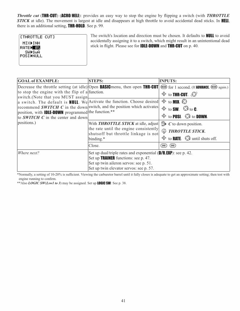
41
Throttle cut (THR-CUT) (ACRO HELI THROTTLE STICK at idle). The movement is largest at idle and disappears at high throttle to avoid accidental dead sticks. In HELI,there is an additional setting, THR-HOLD. See p. 99.
The switch's location and direction must be chosen. It defaults to NULL to avoid accidentally assigning it to a switch, which might result in an unintentional dead
IDLE-DOWN and THR-CUT on p. 40.
GOAL of EXAMPLE: STEPS: INPUTS:Decrease the throttle setting (at idle) to stop the engine with the flip of a switch.(Note that you MUST assign a switch. The default is NULL . We recommend SWITCH C in the down position, with IDLE-DOWN programmed to SWITCH C in the center and down positions.)
Open BASICmenu, then open THR-CUTfunction.
for 1 second. (If ADVANCE, again.)
C to THR-CUT.Activate the function. Choose desired switch, and the position which activates the function.**
C to MIX.C to SW. to C.C to POSI. to DOWN.
With THROTTLE STICK at idle, adjust the rate until the engine consistently shutsoff but throttle linkage is not binding.*
C to down position.
THROTTLE STICK.C to RATE. until shuts off.
Close.
Where next? D/R,EXP): see p. 42.Set up TRAINER functions: see p. 47.Set up twin aileron servos: see p. 51.Set up twin elevator servos: see p. 57.
**Also LOGIC SW(Lsw1 to 3) may be assigned. Set up LOGIC SW: See p. 38.

42
D/R,EXP): assigns adjusted rates and exponential.
Dual/Triple Rates:(ACRO GLID) they can be engaged by any stick position. Dual rates affect the control listed, such as aileron, not just a single (ex: channel 1) servo. For example, adjusting aileron dual rate will affect both aileron servos when using FLAPERON or AIL-DIF, and both aileron and elevator servos’ travel when using AILEVATOR or ELEVON or a CCPM helicopter.
Activation:• Any SWITCH, A-H. If you choose a 3-position switch, then that dual rate instantly becomes a triple rate (see example). • The glider programming offers you the choice of Cond. This option allows you to have a separate rate for each of
condition. (GLID)• Stick position (ACRO GLID
throw, the rudder responds at your lower rate, allowing small, gentle corrections. When the stick passes 90% (ie. stall turn), the rudder goes to high rate’s 90%, which is a MUCH higher amount of travel than your low rate at 89%.)
Ex: (At 100% = 1”) Low Rate = 50% High Rate = 100%At 89% Low Rate = .45”At 90% High Rate = .9”
[Note] Only if any stick is chosen by the item of "SW1", a switch can also be chosen by the item of "SW2." When operated simultaneously, the switch operation has priority over the stick operation. (ACRO)
Adjustability:• Range: 0 - 140% (0 setting would deactivate the control completely.) Initial
value=100%• Adjustable for each direction (ACRO GLID
the amount required to hold the model inverted, the model now has equal travel available from level upright or level inverted.)
Exponential:make the servo movement less or more sensitive around neutral for rudder, aileron, elevator, and throttle (except HELI type - use THROTTLE CURVE instead). (ACRO type—throttle EXP and THROTTLE CURVE can not be activated simultaneously. Why use expo? Many models require a large amount of travel to perform their best tricks. However, without exponential,
by setting different exponentials for each rate, you can make the effectiveness of small corrections similar in each rate, as in our example below.
The best way to understand exponential is to try it: • Having made no changes yet in the D/R,EXP screen, move SWITCH D to “down” (toward the AILERON STICK).• Cursor down to EXP and dial to +100%. • Move SWITCH D up. Hold the AILERON STICK SWITCH D down. • Notice how much less travel there is.
High Rate
High Rate
High RateLow Rate
Low Rate
100% 100%
100%30%0%
90% 90%0%

43
Adjustability:• More sensitive around neutral. (positive exponential, see example) • Less sensitive around neutral. (negative exponential, see example) • Adjustable for each direction. (ACRO GLID)
For throttle, exponential is applied at the low end to help nitro and gasoline engines have a linear throttle response, so that
Special note for helicopters: Helicopter model types have just a single rate for each switch position rather than a rate for each side of the servo’s travel per switch position. Additionally, setting the D/R,EXP for each switch position requires cursoring back to the No.setting, allowing dual rates to be assigned with idle-up and other features on certain switches, and does not require putting
Special note for conditions: The helicopter and glider programming offers you the choice of Cond.. This option allows you to have a separate rate for each of the 3 controls automatically selected when changing conditions, for a total of FIVE rates available. Simply change the switch choice to Cond. and then:(HELI) press the CURSOR LEVER to toggle through the 5 conditions while setting the rates.(GLID) activate the corresponding condition to edit the rates.
GOAL of EXAMPLE: STEPS: INPUTS:Set up dual rates and exponential in a HELI model.
Open D/R,EXP. for 1 second. (If ADVANCE, again.)
C to D/R,EXP.Choose channel. C to desired channel.
C to No>. to UP.Set rate and exponential (Ex: high rate = 95%, 0% exponential.)
C to D/R>. to 95%.
0% EXP.Go to 2nd switch position and set rate and exponential.
C to No>. to DN.
Repeat above.Optional: if using a 3 position switch, set 3rd rate.
C to No>. to CT.
Repeat above.Optional: assign dual rates to have one for each condition.
C to SW. to COND.
Repeat steps above to adjust for each condition.

44
GOAL of EXAMPLE: STEPS: INPUTS:Set up aileron triple rates on SWITCHC with travel settings of 75% (normal), 25% (slow roll) and 140% (extreme aerobatics) and exponential settings of 0%, +15%, and -40% respectively.
NOTE: Th i s no rma l r a t e has no exponential so it has a very linear, normal feel. This slow roll rate has positive exponential (the opposite of what most people normally use), which makes the servos more responsive around center. This makes the servos feel the same around center in the normal and low rates, but still gives a very slow roll rate at full stick.
The 3D rate (extreme aerobatics) has a very high distance of travel B nearly twice that of the normal rate. Therefore, using a very high negative exponential setting softens how the servos respond around center stick. This makes the servos respond similarly around center stick for a more comfortable feel.
Many modelers like to set up all 3 triple rates on a single 3-position switch, creating a “slow and pretty mode”, a “normal mode”, and a “wild stunts mode” all with the flip of a single switch. To do so, simply set up rates for all 3 controls and assign all 3 to the same 3-position switch.
Open D/R,EXP function. for 1 second. (If ADVANCE, again.)
C to D/R,EXP.Choose the channel to change (Ex: aileron is already selected)
C to desired channel.
Optional: change switch assignment. C to SW1. to C.Confirm switch is in desired position and set rate. (Ex: up = high rate, 75%).
C to D/R>.
C to up position.
AILERON STICK. to 75%.
AILERON STICK. to 75%.Move SWITCH to 2nd rate position and set this particular rate. (Ex: center = low rate, 25%).
C to center position.
AILERON STICK. to 25%.
AILERON STICK. to 25%.Optional: if using a 3 position SWITCH, move SWITCH to 3rd position and set this rate (Ex: down = 3D rate, 140%).
C to down position.
AILERON STICK. to 140%.
AILERON STICK. to 140%. Optional: instead of using a switch, you can set high rates to be triggered when the stick moves past a certain point. To test this, set aileron high rate to 25%. Now set switch assignment to AIL (90%). Move AILERON STICKto the right and notice the huge jump in travel after the stick moves 90% of its distance.
C to SW1. to AILE (90%).C to D/R>.
AILERON STICK. to 25%.
AILERON STICK. to 25%.
AILERON STICK and watch screen graph. See the change?!
You may also change the trigger point by holding the stick at the desired point, then pressing and holding the DIAL.
Set each rate’s EXP.(Ex: 0%, +15%, -40%)
C to EXP>.
C to up position.
EXP reads 0.
C to down position.
AILERON STICK. to +15%.
AILERON STICK. to + 15%.
C to center position.repeat to set low rate expo to -40%.
Repeat above steps for elevator and rudder. Close.
Where next?Set up TRAINER functions: see p. 47.Adjust the sensitivity of the trims: see p. 48.Set up twin aileron servos: see p. 51.Set up twin elevator servos: see p. 57.

45
TIMER submenu (stopwatch functions): controls three electronic clocks used to keep track of time remaining in a
Adjustability:• Count down timer: starts from the chosen time, displays time remaining. If the time is exceeded, it continues to count
below 0. • Count up timer: starts at 0 and displays the elapsed time up to 99 minutes 59 seconds. • Count down timer (Stop type): starts from the chosen time, displays time remaining, and stops at 0.• Model timer: cumulates ON time up to 99 hours 59 minites each model. Once Model timer function is turned off, the
cumulate time will also be reset to "0:00". • Independent to each model, and automatically updates with model change. • In either TIMER mode, the timer beeps once each minute. During the last twenty seconds, there's a beep each two seconds.
DOWN TIMER)• To Reset, choose the desired timer with the CURSOR lever (while at the startup screen), then press and hold DIAL for 1
second.• Activation by either direction of SWITCH A-H, by THROTTLE STICK (STK-THR) (Using the THROTTLE STICK is
convenient if you are keeping track of fuel remaining, or for an electric, how much battery is left), by LOGIC SWITCH Lsw1-Lsw3 or by the power SWITCH (PWR SW). Set up LOGIC SW: See p. 38.
• Also the reset switch can be assigned (SWITCH A-H or LOGIC SWITCH Lsw1-Lsw3)
GOAL of EXAMPLE: STEPS: INPUTS:
being control led by THROTTLE STICK position. This is utilized to keep track of actual Throttle on time to better
Open BASIC menu, then open TIMERfunction.
for 1 second. (If ADVANCE, again.)
to page 2.C to TIMER.
Go to TIMER<2>. C to 10 (TIMER<2>).Adjust time to 4 min. 30 sec., count down.
to 4. C to 00 (TIMER<2>).
to 30.Assign to THROTTLE STICK and set trigger point.
C to ON>SwA (TIMER<2>).
to STK THR.C to 50%. for 1 second to NULL.
THROTTLE STICK to desired
for 1 second to set.Close.
Where next? Adjust END POINTs
Set up TRAINER functions: see p. 47.
TIMER<1>
TIMER<2>
TIMER<3>(Home screen)

46
Auxiliary channel function (including channel 9-10 controls)(AUX-CHcontrols and the receiver output for channels 5-10. Also, the CH9-10 POSI are used to change the CH9-10 servo direction. Note that the CH9-10 functions are only visible in the AUX-CH screen when PCM or 2.4H-10CH modulation is selected. The 9-10th channels are not supported in FM modulation. The 8-10th channels are not supported in 2.4G-7CH modulation.
Adjustability:• channels 5-8 may be assigned to any SWITCH (A-H), LOGIC SWITCH
(Lsw1-Lsw3), slider [VR(D) and VR(E)], or knob [VR(A-C)] (for example, moving flaps to a switch or slider), but not the primary control sticks (use programmable mixes to do so, p. 68);
• channel 9-10 may be assigned to any SWITCH (A-H), LOGIC SWITCH (Lsw1-Lsw3) and the servo direction may be changed.
• multiple channels may be assigned to the same switch, slider or knob; • channels set to "NULL" are only controlled by mixes. (Ex: utilizing 2 channels
for 2 rudder servos. See mixes, p. 68.) • If GYRO SENSE, GOVERNOR, and THR-NEEDLE functions are activated, AUX-CH
settings of related channels become invalid automatically. Related channels: GYRO SENSE (ACRO): ch. 5, 7, or 8: see p. 73.GYRO SENSE (HELI): ch. 5: see p. 107.GOVERNOR (HELI): ch. 7, or ch. 7 and 8: see p. 108.THR-NEEDLE (ACRO HELI): ch. 8: see p. 65.
Remember that if you assign primary control of a channel to a switch which you later use for other functions (like
GOAL of EXAMPLE: STEPS: INPUTS:VR(E)]
and set channel 7 to NULL in preparation to use it as a smoke system control (the smoke system being activated later by a throttle-to-ch.-7 mix).
Open BASIC menu, then open AUX-CHfunction.
for 1 second. (If ADVANCE, again.)
to page 2. C to AUX-CH.Choose the channel to change. (ex: ch. 6.)
C to Ch 7.
Change primary control. (ex: to slider.) to Vr-E.Repeat as needed. (ex: ch. 7 to NULL.) C to Ch 7. to NULL.Close.
Where next? Programmable mixes: see p. 68.D/R,EXP): see p. 42.
Adjust SUB-TRIM of auxiliary channel to adjust center SWITCH position: see p. 49.Adjust END POINTs (sets end points of travel even when using a switch): see p. 39.

47
TRAINER: for training novice pilots with optional trainer cord connecting 2 transmitters. The instructor has several levels of controllability.
Adjustability:• NORM: When the TRAINER SWITCH is ON, the channel set to this mode can
be controlled by the student. The set channel is controlled according to any programming set at the student's transmitter.
• FUNC: When the TRAINER SWITCH is ON, the channel set to this mode can be controlled by the student, controlled according to any mixing set at the instructor's transmitter.
• MIX: When the TRAINER SWITCH is ON, the channel set to this mode can be controlled by both the student and the instructor, controlled according to any mixing set at the instructor's transmitter. And the student's mixing rate is adjustable. (default 30%)
[Note] However, it becomes invalid even if it sets up the channel which is not in a student's transmitter. The channel serves as operation by the instructor's transmitter automatically.
• OFF: The channel set to this mode cannot be controlled by the student even when the TRAINER SWITCH is ON. The set channel is controlled by the instructor only, even when the TRAINER SWITCH is ON.
• SWITCH: controlled by spring-loaded SWITCH F (10CA) or H (10CH) only. Not assignable. • Compatibility: The 10C may be master or student with any Futaba transmitter compatible with the cord. Simply plug
the optional trainer cord (For 10C series, sold separately) into the trainer connection on each transmitter, and follow the guidelines below.
Examples:FUNC,
5-channel helicopter practice is possible with a 4-channel transmitter.
• Set up the model in a second transmitter, use NORM mode to quickly and safely check proper operation of all functions, then allow
• Using NORM mode, set lower throws, different exponentials, even different auxiliary channel settings on the student radio (if it has these features).
• To ease the learning curve, elevator and aileron may be set to the NORM or FUNCmode, with the other channels set to OFF and controlled by the instructor.
GOAL of EXAMPLE: STEPS: INPUTS:Turn on the TRAINER system and set up so student has: fully functional control of aileron and elevator to support F L A P E R O N and A I L E VAT O R ; normal control of rudder to allow lowered travel; and no throttle channel control (with the instructor for safety).
Open BASICmenu, then open TRAINERfunction.
for 1 second. (If ADVANCE, again.)
to page 2. C to TRAINER.Activate TRAINER. to OFF.Choose desired channel(s) and proper training type(s).
C past AIL and ELE (default OK).C to THR, to OFF.C to RUD, to NORM.
Close.
Where next? Set student 10C to PPM (required regardless of receiver's modulation): see p. 35. D/R,EXP) on student 10C: see p.42.
Reset trims on student 10C: see p. 48.
Precautions: • NEVER turn on the student transmitter power. • ALWAYS set the student transmitter modulation mode to PPM.• BE SURE that the student and instructor transmitters have identical trim
settings and control motions. Verify by switching back and forth while moving the control sticks.
• FULLY extend the instructor's antenna. Collapse the student's antenna. (except 2.4GHz)
• Always remove the student transmitter's RF module (if it is a module-type transmitter).
• When the TRAINER function is active, the snap roll function is deactivated. Other functions, such as IDLE-DOWN and THR-CUT, which have been assigned to the same switch, are not deactivated. Always double check your function assignments prior to utilizing the TRAINER function.
• When you select a different model, the TRAINER function is deactivated in the current model for safety reasons.

48
TRIM submenu: resets and adjust effectiveness of digital trims.
The 10C has digital trims which are different from conventional mechanical trim sliders. Each TRIM LEVER is actually a two-direction switch. Each time the TRIM LEVER is pressed, the trim is changed a selected amount. When you hold the TRIM LEVER, the trim speed increases. The current trim position is graphically displayed on the start up screen. The TRIM submenu includes two functions that are used to manage the trim options.
HELI models only: OFFSET is available in the idle ups. If OFFSET is inhibited, adjustment of the TRIM LEVERS will adjust OFFSET is active, then moving the trims within any one condition will effect only that
condition. See OFFSET, p. 102.
Trim reset (RESET): electronically centers the trims to their default values. Note that the SUB-TRIM settings and the trim STEP rate are not reset by this command.
GOAL of EXAMPLE: STEPS: INPUTS:Reset trims to neutral after having adjusted all linkages.N O T E : T h i s i s o n e o f s e v e r a l functions for which the radio requires
Open BASICmenu, then open TRIMsubmenu.
for 1 second. (If ADVANCE, again.)
C to TRIM.Request . for 1 second.
Beep sounds.Close.
Where next? Adjust SUB-TRIMs: see p. 49.Adjust trim rate (STEP): see below.Adjust END POINTs: see p. 39.
D/R,EXP): see p. 42.
Trim step (STEP): changes the rate at which the trim moves when the TRIM LEVER is activated. It may be set from 1 to 40 units, depending on the characteristics of the aircraft. Most ordinary aircraft do well at about 2 to 10 units. Generally
GOAL of EXAMPLE: STEPS: INPUTS:Double the sensitivity (larger step) ofthe AILERON TRIM LEVERS for a first flight of an aerobatic model to ensure sufficient range to trim the model for
Open TRIM submenu and choose the STEP you wish to change. (Ex: aileron)
for 1 second. (If ADVANCE, again.)
C to TRIM.Adjust the size of the step. (Ex: incr. to 8)
C to AILE. to 8.
Repeat as desired for other channels. C to ELEV. to new setting.Repeat as needed.
Close.
Where next? Adjust sub trims: see p. 49.Adjust END POINTs: see p. 39.
D/R,EXP): see p. 42.

49
SUB-TRIM: makes small changes or corrections to the neutral position of each servo. Range is -120 to +120, with 0 setting, the default, being no SUB-TRIM.
We recommend that you center the digital trims before making SUB-TRIMchanges, and that you try to keep all of the SUB-TRIM values as small as possible. Otherwise, when the SUB-TRIMs are large values, the servo's range of travel is restricted on one side.
The recommended procedure is as follows: • measure and record the desired surface position; • zero out both the trims (TRIM RESET menu) and the SUB-TRIMs (this menu); • mount servo arms and linkages so that the control surface’s neutral is as correct as possible; and • use a small amount of SUB-TRIMGOAL of EXAMPLE: STEPS: INPUTS:
SUB-TRIM untilits center exactly matches the aileron servo's center, as they are to work
Open BASICmenu, then open SUB-TRIM. for 1 second. (If ADVANCE, again.)
C to SUB-TRIM.Choose the channel to adjust, andadjust C to FLAP
as needed. C to each channel, Repeat for other channels. as needed.Close.
Where next? Adjust trim steps: see p. 48.Adjust END POINTs: see p. 39.
D/R,EXP): see p. 42.
The servo submenu includes two features: • real-time bar-graph display to demonstrate exactly what commands the
transmitter is sending to the servos. (This can be particularly handy in setting up models with complicated mixing functions, because the results of each stick, lever, knob, switch input and delay circuit may be immediately seen.)
(channels 1-8)
GOAL of EXAMPLE: STEPS: INPUTS:View the result of reassigning channel 6 from VR(A) knob to three-position SWITCH C.
Cycle the channel 6 servo.
Comple t e de s i r ed p rog ramming function. (Ex: in AUX-CH, move ch. 6 to SWITCH C)
See AUX-CH for details. (p. 39.)
Open the SERVO function. for 1 second. (If ADVANCE, again.)
C to SERVO.Move each control to see exactly how operating. (Ex: SWITCH C in all positions)
C to center position.Note change in position of ch. 6 servo.
Prepare all servos to be cycled and cycle. Plug in servos. POWER ON.End cycling and close.
Where next? D/R,EXP): see p. 42.Set up desired programmable mixes: see p. 61.Set up dual aileron servos: see p. 51.Set up dual elevator servos: see p. 57.
SERVO display and cycle submenu: displays radio's output to channels 1-10.

50
FailSafe (loss of clean signal and low receiver battery) submenu (PCM 2.4G mode only) (F/S): sets responses in case of loss of signal or low Rx battery.
FailSafe (F/S
Adjustability:• Each channel may be set independently. (2.4G-7CH mode: ch3 only)• The NOR (normal) setting holds the servo in its last commanded position. • The F/S (FailSafe) function moves each servo to a predetermined position. • NOTE: the setting of the throttle's F/S also applies to the Battery F/S (see
below).
Examples:• The F/S
as possible. • Competition modelers often maintain the NOR function so that brief interference will not affect their model's maneuver. • Set the throttle channel so that the engine idles when there is interference (ACRO
from and recover from the radio interference and minimize damage if crashed. • For helicopters, NOR is typically the safest choice. • We also recommend setting a gasoline engine's electronic kill switch to the OFF position in the F/S function for safety reasons.
Updating F/S Settings: If you specify a F/S setting, the FailSafe data is automatically transmitted once each two minutes. (PCM) When you choose the F/S mode, check that your settings are as desired by turning off the transmitter power switch and verifying that the servos move to the settings that you chose. Be sure to wait at least two minutes after changing the
GOAL of EXAMPLE: STEPS: INPUTS:Change the receiver FailSafe command for channel 8 (gasoline engine kill switch) to a preset position.
N O T E : T h i s i s o n e o f s e v e r a l functions for which the radio requires
Open the BASIC menu, then open F/Sfunction.
for 1 second. (If ADVANCE, again.)
C to F/S.Choose Channel to change. (ex: Ch. 8) C to Ch 8.Set and fail safe command. that controls channel 8 to desired
OFF position.
for 1 second to store.Repeat as desired.Close.
Where next? F/S settings as described above.Read below for information on Battery FailSafe.Adjust END POINTs to gain proper F/S responses if needed: see p. 39.Adjust SUB-TRIM to gain proper F/S responses if needed: see p. 49.
Battery FailSafe (F/S): a second battery low warning feature (separate from the transmitter low voltage warning). When F/S function moves the
throttle to a predetermined position. When the Battery F/S function is activated, your engine will move to idle (if you haven't set a position) or a preset position. You should immediately land. You may temporarily reset the Battery F/Sfunction by moving the THROTTLE STICK to idle. You will have about 30 seconds of throttle control before the battery function reactivates.
Adjustability:• NOR F/S setting for throttle results in Battery F/S going to the servo position reached by moving THROTTLE STICK to
the bottom with TRIM LEVER centered; • F/S position setting for throttle results in Battery F/S also going to the same throttle servo position as the regular F/S.
If using a 6V (5-cell) receiver battery, it is very likely that your battery will be rapidly running out of charge before battery FailSafe takes over. It is not a good idea to count on battery FailSafe to protect your model at any time, but especially when using a 5-cell battery.

51
ACRO ADVANCE MENU FUNCTIONS:
Aircraft wing types (ACRO GLID):There are 3 basic wing types in aircraft models: • Simple. Model uses one aileron servo (or multiple servos on a Y-harness into a single receiver channel) and has a tail.
This is the default setup and requires no specialized wing programming. • Twin Aileron Servos. Model uses 2 aileron servos and has a tail. see Twin Aileron Servos. • Tail-less model (flying wing). Model uses 2 wing servos working together to create both roll and pitch control. see
ELEVON.
Twin Aileron Servos (with a tail) (ACRO GLID): Many current generation models use two aileron servos, plugged into two ELEVON, p. 56.)
• Ability to adjust each servo's center and end points for perfectly matched travel. • Redundancy, for example in case of a servo failure or mid-air collision. • Ease of assembly and more torque per surface by not requiring torque rods for a single servo to drive 2 surfaces.
• Set a negative percentage to reverse the operation of one of the servos.
Options:• 5-channel receiver. Set up AILE-2 (see p. 55) prior to continuing with FLAPERON or AIL-DIFF.• FLAPERON:
•Uses CH6 for the second servo (see AIL-2 to use CH5.)
•Provides FLAP-TRIM•Also allows aileron differential in its own programming (instead of activating AIL-DIFF).
• Aileron Differential (AIL-DIFF):•Uses CH7 for the 2nd servo (see AIL-2 to use CH5.)
AIRBRAKE. (see p. 63). •Allows for more up aileron travel than down for straighter rolls.
You will need to choose which of FLAPERON or AIL-DIFF is the better choice for your model's setup. If you need the ailerons FLAPERON AIL-DIFF
is probably the easiest choice. (For details on setting up a complex aerobatic plane, such as one with 4 wing servos using AIRBRAKE
com\faq\. Many other setup examples are also available at this location.)
NOTE: Only one of the three wing-type functions (FLAPERON, AIL-DIFF, and ELEVON) can be used at a time. All three
GOAL of EXAMPLE: STEPS: INPUTS:De-activate FLAPERON so that AIL-DIFF or ELEVON can be activated.
Open the FLAPERON function. for 1 second. (If BASIC, again.)
C to FLAPERON.De-activate the function. C to MIX. to INH.Close function.
Where next? Set up AILE-DIFF (see p. 54) or ELEVON (see p. 56).

52
Using FLAPERON (ACRO GLID 1A+1F ):
The FLAPERON
performed.
[Note] When changing the polarity of a rate, "change rate dir?" is displayed for a check. Please set up after pressing DIAL for 1 second and canceling an alarm display. (GLID only)
Once FLAPERON ELEVATOR-FLAP mixing), the radio commands both FLAPERON. A trimming
feature is also available (see FLAP-TRIMEND POINT and SUB-TRIM both still adjust each servo individually.
Adjustability:• Each aileron servo's up travel can be set separate from its down travel, creating aileron differential. (See example).
• AILE-2 AILE-2 function only commands the FLAP-
TRIM• The separate FLAPERON settings for each condition can be set. (GLID)
FLAP-TRIM
AIRBRAKEELEVATOR-FLAP FLAP-TRIM is activated.
GOAL of EXAMPLE: STEPS: INPUTS:Activate twin aileron servos, FLAPERON.
Input 10% less down travel than up travel (aileron differential) within the FLAPERON programming. (Decrease right aileron is down travel to 90%, decrease left aileron's down travel to 90%.)
of aileron travel available.
Open the FLAPERON function. for 1 second. (If BASIC, again.)
C to FLAPERON.Activate the function. C to MIX. to ACT.Optional: adjust the up/down travel separately for the 2 servos.(Ex: 90% down.)
C to AIL1. AILERON STICK.
to 90%.C to AIL2. AILERON STICK.
to 90%.Optional: adjust the aileron's travel so
travel to 50%.)
C to FLP2. to +50%.C to FLP1. to -50%.
Close menu.
Where next? Set FLAP-TRIM: see p. 53.Set up AIRBRAKE mix: see p. 63.
* If you receive an error message that OTHER WING MIXING IS ON, you must deactivate AIL-DIFF or ELEVON. see p. 51.
(GLID 1A+1F)(ACRO)

53
Using FLAP-TRIM (ACRO GLID )
FLAP-TRIM assigns the primary flaperon control [defaults to VR(A)] to allow trimming in flight of the flap action of FLAP-TRIM is made active with AIL-DIFF, it will not have any effect. The ONLY function that allows
AIL-DIFF AIRBRAKE.) Most modelers use AIRBRAKE, or programmable
FLAP-TRIM
changing the Flap Trim travel. (Note that there is only one setting, not independent settings for up and down travel.)
GOAL of EXAMPLE: STEPS: INPUTS:Add FLAP-TRIM to allow the model's
at any time during the flight,with a maximum travel of 5%travel set in FLAPERON.
Open the FLAP-TRIM function. for 1 second. (If BASIC, again.)
C to FLAP-TRIM.The function is automatically activated with FLAPERON; however, the default travel is 0.Adjust the travel available to the f laperons when turn ing the CH6 DIAL.(Ex: 5%).
to 5%.
Optional: Use as total flap control.Reassign CH6 is primary control in AUX-CH(Ex: right slider)
to 50%.C to AUX-CH.
C to CH6. to Vr-E.Close menu.
Where next? Adjust individual servo's SUB-TRIMs: see p. 49 and END POINTs: see p. 39. Set up AIRBRAKE mix: see p. 63 and ELEV-FLAP mix: see p. 62.
see p. 61.View additional model setups on the internet: www.futaba-rc.com\faq\.
(GLID)(ACRO)

54
Using Aileron Differential (AILE-DIFF)(ACRO GLID 2A+1F GLID 2A+2F):
& CH6, and AILE-DIFF controlling proper aileron operation of 2 aileron servos, plugged into CH1 and CH7. The ailerons AILE-DIFF, except if using AIRBRAKE (see p. 63.) (Note that even if you make FLAP-
TRIM active while using AILE-DIFF, it will not have any effect. ONLY AIRBRAKE AILE-DIFF
Please set up after pressing DIAL for 1 second and canceling an alarm display. (GLID only)
• The separate AILE-DIFF settings for each condition can be set. (GLID only)
GOAL of EXAMPLE: STEPS: INPUTS:Activate twin aileron servos using AIL-DIFF.Note that the function defaults to no difference in down travel vs. up travel. If you want differential travel, simply adjust each side. (Ex: 90%)
Open the AIL-DIFF function. for 1 second. (If BASIC, again.)
C to AIL-DIFF. *Activate the function. C to MIX. to ACT.
separately for the 2 servos. (Ex: adjust to 90%.)
C to AIL1. AILERON STICK.
to 90%.C to AIL2. AILERON STICK.
to 90%.Close menu.
Where next? Adjust individual servo's SUB-TRIMs: see p. 49 and END POINTs: see p. 39. Set up AIRBRAKE mix: see p. 63.Set up ELEV-FLAPSet up SNAP-ROLL Function: see p. 59. View additional model setups: www.futaba-rc.com\faq\.
*If you receive an error message that OTHER WING MIXING IS ON, you must deactivate ELEVON or FLAPERON. See p. 51.
(GLID 2A+1F GLID 2A+2F)(ACRO)

55
Using Twin Aileron Servos with a 5-channel receiver, AILE-2 (ACRO GLID ):
AILE-2 allows FLAPERON and AIL-DIFF with a 5-channel receiver. AILE-2 only tells the radio that you are using CH5 and CH6 (FLAPERON), or CH5 and CH7 (AIL-DIFF), not CH6 or CH7, as the second servo in FLAPERON or AILE-DIFF. You still must activate and set up the FLAPERON AILE-DIFF function.
Note that selecting CH6&5 or CH7&5 does NOT free up CH6 or CH7 to be used for other functions when using a receiver with more than 5 channels. Both 5 and 6 (FLAPERON AILE-DIFF) are dedicated to the FLAPERON or AILE-DIFF programming.
CH6 are already fully set up to operate as ailerons. Mix CH7 or CH8 (the second aileron servo on the other side) into ailerons to function properly.]
Aircraft tail types (ACRO GLID):
GOAL of EXAMPLE: STEPS: INPUTS:Adjust the second aileron servo output from CH6or7 to channels CH6&5.
Allows twin aileron servo operation with a 5-channel receiver.
Open the PARAMETER submenu. for 1 second. (If ADVANCE, again.)
C to PARAMETER.Select AILE-2 and change to CH6&5. C to AILE-2. to CH6&5.Close menu.
Where next? Finish setting up FLAPERON or AILE-DIFF. see Twin Aileron Servos: p. 51.View additional model setups on the internet: www.futaba-rc.com\faq\

56
There are 4 basic tail types in aircraft models:• Simple. Model uses one elevator servo and one rudder servo (or multiple servos on a Y-harness). This is the default. • Dual Elevator servos. Model uses 2 elevator servos. see AILEVATOR (ACRO) see p. 57. • Tail-less model. Model uses 2 wing servos together to create roll and pitch control. see ELEVON(ACRO GLID 1A+1F). see p. 56. • V-TAIL. Model uses 2 surfaces, at an angle, together to create yaw and pitch control. see V-TAIL (ACRO GLID). see p. 58.
Note: Only one of the three tail-type functions (AILEVATOR, V-TAIL, and ELEVON) can be used at a time. The radio provides a OTHER WING
MIXING IS ON will display. (See the wing type example on page 51.)
Using ELEVON(ACRO GLID 1A+1F
independently. This is also popular for ground model use, such as tanks, which drive two motors together for forward, and
Adjustability:• Requires use of CH1 and CH2.• Independently adjustable aileron travel allows aileron differential. • Independently adjustable elevator travel allows for differences in up vs. down
travel.• The separate ELEVON settings for each condition can be set. (GLID only)
[Note] When changing the polarity of a rate, "change rate dir?" is displayed for a check. Please set up after pressing DIAL for 1 second and canceling an alarm display. (GLID only)
NOTE: If ELEVON is active, you cannot activate FLAPERON, AILE-DIFF, or AILEVATOR. An error message OTHER WING MIXING IS ON displays and you must deactivate the last function to activate ELEVON.
setup. If large travels are specified, when the AILERON and ELEVATOR STICKS are moved at the same time the controls may bind or run out of travel.
( For details on setting up a complex aerobatic plane, please visit www.futaba-rc.com\faq\. Many other setup examples are also available at this location. )
GOAL of EXAMPLE: STEPS: INPUTS:Activate ELEVON.Adjust aileron down travel to 90% of up travel, creating aileron differential.
Open the ELEVON function. for 1 second. (If BASIC, again.)
C to ELEVON.Activate the function. C to MIX. to ACT.Optional: adjust the up/down travel separately for the servos as ailerons. (Ex: down to 90%.)
C to AIL1. AILERON STICK.
to 90%.C to AIL2. AILERON STICK.
to 90%.Optional: adjust the elevator travel of each servo. (Ex: right servo elev. travel to 98%, left to 105%.)
C to ELE2. to 98%.C to ELE1. to 105%.
Close menu.
Where next? Adjust individual servo's SUB-TRIMs: see p. 49 and END POINTs: see p. 39. D/R,EXP): see p. 42.
View additional model setups on the internet: www.futaba-rc.com\faq.html
(GLID 1A+1F)
(ACRO)

57
Dual Elevator Servos (with a rudder) (AILEVATOR) (ACRO): Many models use two elevator servos, plugged in separate receiver channels. (Flying wings without a separate aileron control use ELEVON. V-shaped tail models use V-TAIL, p. 58.
• Ability to adjust each servo's center and end points for perfectly matched travel.
• Ease of assembly, not requiring torque rods for a single servo to drive 2surfaces.
• Redundancy, for example in case of a servo failure or mid-air collision.
Adjustability:• CH2 and CH8 only. (With programmable mixing, could utilize CH5 as the 2nd elevator servo. See www.futaba-rc.com\
faq\ for examples.) THROTTLE-NEEDLE uses CH8 and cannot be active simultaneously. • Direction of each servo's travel may be reversed in REVERSE or the set percentages may be reversed here. • Elevator travels independently adjustable (both directions and percent). • Optional action as ailerons (defaults to 50%
AIL1 and 2 to 0 AIL1 and 2 to 0 here, and use 2mixes . AIL-to-ELEV and AIL-to-AUX2assigned switch is on. See p. 68.
AIRBRAKE/crow etc, please visit www.futaba-rc.com\faq\. Many other setups are also available.)
The AILEVATOR mixing function uses one servo on each of the two elevators, and combines the elevator function with the aileron function (unless aileron travel is set to 0). For aileron effect, the elevators are raised and lowered opposite of one another in conjunction with the ailerons.
Once AILEVATORprogramming moves your ailerons (ie. RUDDER-AILERON mixing), the radio automatically commands both elevator servos to also operate as ailerons. To deactivate this action, simply set the 2 aileron travel settings to 0 in the AILEVATOR function. This way the elevators will work only as elevators.
GOAL of EXAMPLE: STEPS: INPUTS:Activate twin elevator servos.Deactivate the elevator-acting-as-ailerons portion of this function.
Note: Depending upon your model's geometry, you may need to reverse oneservo or set a negative percentage here.
Open the AILEVATOR function. for 1 second. (If BASIC, again.)
C to AILEVATOR.Activate the function. C to MIX. to ACT.Optional: adjust up/down travel when operating as ailerons. (Ex: 0.)
C to AIL3. to 0%.C to AIL4. to 0%.
Optional: adjust total elevator travel of each servo. (Ex: right servo elevator travel to 98%, left to 96%.)
C to ELE2. to 98%.C to ELE1. to 96%.
Close menu.
Where next? Adjust individual servo's SUB-TRIMs: see p. 49 and END POINTs: see p. 39.Set up Twin Aileron Servos: see p. 51.Set up AIRBRAKE mix: see p. 63.

58
Using V-TAIL (ACRO GLID):
V-TAIL mixing is used with v-tail aircraft so that both elevator and rudder functions are combined for the two tail surfaces. Both elevator and rudder travel can be adjusted independently on each surface.
NOTE: If V-TAIL is active, you cannot activate ELEVON or AILEVATOR functions. If one of these functions is active, an error message will be displayed and you must deactivate the last function prior to activating ELEVON. see the wing example on page 51.
NOTE: Be sure to move the elevator and rudder sticks regularly while checking the servo motions. If a large value of
travel until no binding occurs.
Adjustability:• Requires use of CH2 and CH4. • Independently adjustable travels allow for differences in servo travels. • Rudder differential is not available. (To create rudder differential, set RUD1 and 2 to 0, then use two programmable mixes,
RUD-ELE and RUD-RUD, setting different percents for up and down. These are your new rudder travels. Trim and link off, switch assignment null so you can’t accidentally turn off rudder. see PROG.MIX, p. 68.)
(For details on setting up a complex plane, such as one with a v-tail AND a separate steerable nosewheel, please visit our FAQ at www.futaba-rc.com\faq\. Many other setup examples are also available at this location.)
GOAL of EXAMPLE: STEPS: INPUTS:Activate V-TAIL.
Adjust left elevator servo to 95% travel to match to right servo's travel.
Open the V-TAIL function. for 1 second. (If BASIC, again.)
C to V-TAIL.Activate the function. C to MIX. to ACT.optional: adjust the travels separately for the 2 servos as elevators. (Ex: set left to 95%.)
C to ELE1. to 95%.Repeat as necessary for other servos.
Close menu.
Where next? Adjust END POINTs: see p. 32 and SUB-TRIMs: see p. 49.D/R,EXP): see p. 42.
Set up ELEV-FLAP mix: see p. 62.View additional model setups on the internet: www.futaba-rc.com\faq\.

59
SNAP-ROLL) (ACRO):
the same input every time. It also removes the need to change dual rates on the 3 channels prior to performing a snap, as SNAP-ROLL always takes the servos to the same position, regardless of dual rates, inputs held during the snap, etc.
Note: Every aircraft snaps differently due to its C.G., control throws, moments, etc. Some models snap without aileron; others snap on elevator alone. Most models snap most precisely with a combination of all 3 surfaces. Additionally, rate of speed and acceleration when using the snap switch will affect how the model snaps. For information on using gyros with airplanes for cleaner precision maneuvers, such as snaps and spins without over rotation, see p. 74.
Adjustability:• Travel: Adjust the amount of elevator, aileron and rudder travel automatically applied. • Range: -120 to +120 on all 3 channels. Default is 100% of range of all 3 channels. • Directions:
Note: for simplicity, the radio refers to snaps that use “UP” or positive elevator as “U” or “UP” snaps. This is more commonly referred to as a positive or inside snap. “D” or “DOWN” snaps are more commonly referred to as negative or outside snaps.
• R/U = Right positive R/D = Right negative L/U = Left positive L/D = Left negative snap roll • Assignment of the 2 switches (DIR-SW1/2) to change snap directions is fully adjustable and optional. If you wish to have
only one snap, leave the switches as NULL. (If assigned, SW1 SW2• Caution: it is critical that you remember if you assigned switches to select the three additional snaps.
• For example, assign SWITCH A SWITCH A for elevator dual rates. SWITCH A DOWN) you pull your snap SWITCH. The model will:
•use the throws set in the snap programming (the low rate elevator has no effect); and
•Both of these may come as a great surprise and risk crashing if you are unprepared. • Safety Switch (SAFE-MOD): a safety may be set up on your landing gear SWITCH, preventing accidental snap rolls while
the landing gear is down. The safety switch is turned on and off with the landing gear SWITCH.• ON: the safety mechanism is activated when the landing gear SWITCH is in the same position as at the time this
feature is changed to ON. Snap rolls will not be commanded even if the snap roll SWITCH is turned on with the gear SWITCH in this position. When the landing gear SWITCH is moved to the opposite position, snap rolls may be commanded.
• OFF: activates the safety mechanism in the opposite position from the ON function. • FREE: the safety mechanism is completely turned off. Snaps can be commanded regardless of the gear SWITCH
POSITION.Note: The location of the safety switch always follows channel 5. If channel 5 is reassigned to switch C, for example, switch C is now the safety. If channel 5 is nulled or used as the second aileron servo, the safety function will not be available.
• Trainer Safety: SNAP-ROLL is automatically disabled when the trainer function is activated.

60
GOAL of EXAMPLE: STEPS: INPUTS:A c t i v a t e S N A P - R O L L . A d j u s t elevatortravel to 55%, rudder travel to 120%SAFE-MOD so snaps can not be performed when gear is down.
snap to 105%.
(Note: using negative percents can change any of the 4 snap directions. For example, change snap 1 to "down" by changing the elevator percent to -100%.)
Open the SNAP-ROLL function. for 1 second. (If BASIC, again.)
C to SNAP-ROLL.Activate the function. C to MIX. to OFF or ON.Adjust the travels as needed. (Ex: elevator to 55%, rudder to 120%.)
C to ELEV. to 55%.C to RUDD. to 120%.
Optional: Activate SAFE-MOD. [Ex: ON when SWITCH E (10CA) or G (10CH) is down, meaning snap function is deactivated when that switch is in the down position.]
E or G up. C to SAFE-MODE
to ON.
snap switch. Notice MIX reading is still OFF.
E or G down. Notice MIX reading changes to ON.
Optional: Assign switches to up/down and left/right. (Ex: Change to the left/down snap and adjust rudder to 105%.)
C to SW1. to A.C to SW2. to B.
A down B down. Repeat steps above to set percentages.
Close menu.
Where next? Set up programmable mixes: see p. 61. View additional setups on the internet:www.futaba-rc.com\faq\.

61
MIXES: the backbone of nearly every functionMixes are special programs within the radio that command one or more channels to act together with input from only one source, such as a stick, slider or knob.
There are a variety of types of mixes. Types:• Linear: Most mixes are linear. A 100% linear mix tells the slave servo to do exactly what the master servo is doing, using
100% of the slave channel’s range to do so. An example is FLAPERONto move exactly the same amount. A 50% linear mix would tell the slave servo, for example, to move to 50% of its range when the master’s control is moved 100%. (see p. 52.)
• Offset: An OFFSETservo is moved a set percent of its range. An example of this is AIRBRAKE
• Curve: Curve mixes are mostly used in helicopters, but may also be used in airplanes and gliders. An example is THROTTLE-NEEDLE mixing, where the in-flight needle’s servo is moved, changing the mixture, as the throttle servo is moved. (see p. 65.)
• Delay: Delay mixes are part of a few very special functions that make the servo move to its desired range more slowly. THROTTLE DELAY (simulates turbine engines, p. 66) and the elevator delay in AIRBRAKE are two examples of this (see p. 62). DELAY in HELI (see p. 103) is another example that slows the servo movement to the trim settings for the other conditions.
to use. Additionally, the 10C ACRO and GLID programs both provide 4 linear and 4 curve fully-programmable mixes (HELIprovides 4 linear and 2 curve) that allow you to set up special mixes to resolve flight difficulties, activate additional functions, etc.
Let’s look quickly at a few examples that are features we’ve already covered. This may help to clarify the mix types and the importance of mixes.
Additional examples: • Exponential is a preprogrammed curve mix that makes the servos’ response more (+) or less (-) sensitive around center
stick (works in conjunction with dual rate, a linear mix that adjusts the total range). see D/R,EXP, p. 42.• IDLE-DOWN and THR-CUT are two OFFSET pre-programmed mixes. These tell the throttle servo, when below a certain point,
to move toward idle an additional set percentage to help close the carburetor. see p. 40. • ELEV-TO-FLAP
model loop even tighter than it can on elevator alone. (see p. 62.)• THROTTLE-NEEDLE mixing is a curve mix (like PROG.MIX 5 to 8• THROTTLE DELAY mixing is a pre-programmed delay mix that slows down the response of the CH3 servo. (see p. 66.)
Next, we'll get an in-depth look at some pre-programmed mixes (simplicity) we’ve not covered yet, and last, look at the fully-programmable mix types.
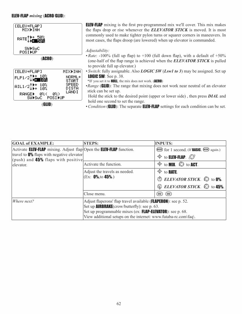
62
ELEV-FLAP mixing (ACRO GLID):
ELEV-FLAPELEVATOR STICK is moved. It is most
commonly used to make tighter pylon turns or squarer corners in maneuvers. In
Adjustability:• Rate
when the ELEVATOR STICK is pulled to provide full up elevator.)
• Switch: fully assignable. Also LOGIC SW (Lsw1 to 3) may be assigned. Set up LOGIC SW: See p. 38.*IF you set it to NULL, the mix does not work. (ACRO)
•Range (GLID): The range that mixing does not work near neutral of an elevator stick can be set up.
Hold the stick to the desired point (upper or lower side) , then press DIAL and hold one second to set the range.
• Condition (GLID): The separate ELEV-FLAP settings for each condition can be set.
(ACRO)
(GLID)
GOAL of EXAMPLE: STEPS: INPUTS:Activate ELEV-FLAP mixing. Adjust flap travel to 0%(push) and 45% flaps with positive elevator.
Open the ELEV-FLAP function. for 1 second. (If BASIC, again.)
C to ELEV-FLAP.Activate the function. C to MIX. to ACT.Adjust the travels as needed. (Ex: 0%,to 45%.)
C to RATE.
ELEVATOR STICK. to 0%.
ELEVATOR STICK. to 45%.Close menu.
Where next? FLAPERON): see p. 52.Set up AIRBRAKESet up programmable mixes (ex: FLAP-ELEVATOR): see p. 68. View additional setups on the internet: www.futaba-rc.com\faq\.

63
AIRBRAKE BUTTERFLY (crow) mixing (ACRO GLID):
Like FLAPERON and AILEVATOR, AIRBRAKE is one function that is really made up of a series of pre-programmed mixes all done for you within the radio. AIRBRAKE(often called "crow" or BUTTERFLY - see GLID, p. 80 for details) simultaneously
limit increases in airspeed in dives.
FLAP-ELEVATOR mixing together.
Adjustability:• Activation: Proportional by moving the THROTTLE STICK• Switch: Mix SWITCH is selectable. *Also LOGIC SW (Lsw1 to 3) may be assigned. Set up LOGIC SW: See p. 38.
• Linear(Inversely proportional to THROTTLE STICK): provides a proportional increase in amount of AIRBRAKEaction as THROTTLE STICK is lowered and assigned switch is on. Provides gradually more AIRBRAKE as you slow the engine. Includes selectable stick position where AIRBRAKE begins, gradually increasing to the same setting as the THROTTLE STICK is lowered. If you would like to have the airbrake be directly proportional to throttle stick, you will need to reverse the THR-REV function. Note that this changes the throttle stick direction for all models. See page 38 for instructions.
• Offset: Provides AIRBRAKE response immediately upon switch movement, going to a pre-set travel on each active channel
• During Airbrake operation, the elevator travel is displayed on the elevator trim display in the Startup screen. • Delayed reaction: You can suppress sudden changes in your model's attitude when AIRBRAKE BUTTERFLY is activated
by setting the delay (delay-ELEVreach their desired end point together. A setting of 100% slows the servo to take approximately one second to travel the prescribed distance. (GLID: B.FLY-ELEV function)
• ACRO): Using the aileron (when AILE-DIFF or FLAPERONcan be set to adjust the aileron and elevator settings in your airbrake rather than adjusting the model's actual aileron and
the trims are again adjusting the normal elevator trim. • Channels controlled AIRBRAKE, including set to 0 to
have no effect. • Twin aileron servos: If FLAPERON, ELEVON and AIL-DIFF functions are inhibited, then AIL1 and AIL2 settings will have no
effect. • If FLAPERON is active, the travel of the ailerons can be independently adjusted for the servos plugged into CH1 and
• If AIL-DIFF is active, then CH1 and CH7 may be independently adjusted. • Normally both ailerons are raised equally in AIRBRAKE, and the elevator motion is set to maintain trim when
the ailerons rise. Different amounts may be set for each aileron to correct for torque reactions and other unique characteristics of the model.
Be sure you understand what dropping ailerons will do when in AIRBRAKE BUTTERFLY. Along with creating an enormous amount of drag (desireble for spot landings), this also creates "wash-in", a higher angle of attack where the ailerons are, and cncourages tip stalling. If you are using this for aerobatic performance and not "sudden stops",
(GLID)(ACRO)

64
GOAL of EXAMPLE: STEPS: INPUTS:Activate AIRBRAKE on a FL APERON.model. Adjust the flaperon travel to 75%,with negative elevator (push) of 25%.
FLAPERON is active. see FLAPERON instructions.Open the AIRBRAKE function. for 1 second. (If BASIC, again.)
C to AIRBRAKE.Activate the function. Switch C in up position.
C to MIX. to OFF.Adjust the travels as needed. (Ex:Ailerons each 75%, Elevator -25%.)
C to AIL1. to 75%.C to ELEV. to -25%.C to AIL2. to 75%.
Opt ional : de lay how quickly the elevator servo responds.
C to delay-ELEV. to 25%.
Optional: change the mixing from full amount upon switch to proportional to the THROTTLE STICK's proximity to idle.
C to MODE. to Linear (0%).
THROTTLE STICK to desired 0point.
for 1 sec, until beeps (display changes if new setting is different from prior setting).
Close menu.
Where next? FLAPERON): see p. 52.Set up ELEV-FLAP mixing: see p. 62.Set up programmable mixes, for example, FLAP-ELEVATOR: see p. 67. View additional model setups on the internet: www.futaba-rc.com\faq\.
• Twin elevator servos: • If AILEVATOR is active, the AIL1 and AIL2 settings still only affect FLAPERON or AIL-DIFF servos, NOT the elevator servos.
(they would have the AIL3 and AIL4 settings.)

65
THROTTLE-NEEDLE mixing (ACRO HELI):
THROTTLE-NEEDLETHROTTLE STICK inputs for perfect engine tuning at all throttle settings. This function is particularly popular with
or installations with a high tank position. Not needed for fuel injection engines, which do this automatically.
Adjustability:• Five-point curve allows adjustment of engine mixture at varied throttle settings.
• The CH8 knob adjusts the high throttle mixture (may be deactivated. see AUX-CH).• Because both use CH8, this function cannot be used simultaneously with AILEVATOR.• An acceleration (ACCE) function (ACRO only) helps the engine compensate for sudden, large amounts of throttle input by
making the mixture suddenly richer, then easing it back to the proper adjustment for that throttle setting. This function
on rapid throttle input. • Separate curves are available (HELI only) for normal, idle-ups 1 and 2 combined, and idle-up 3. Immediately below MIX
the radio displays the curve you are editing; ex: >NORML; and then which condition is currently active by your switches ex: (ID1/2). Note that you can edit the mix for a different condition without being in that condition, to allow editing without having to shut off the helicopter’s engine every time. Be sure you are editing the proper curve by checking the name after the > and not the one in parentheses.
GOAL of EXAMPLE: STEPS: INPUTS:Activate THROTTLE-NEEDLE mixing.Adjust the points as follows to resolve a slight lean midrange problem:
1: 40%2: 45%3: 65%4: 55%5: 40%
Open the THROTTLE-NEEDLE function. for 1 second. (If BASIC, again.)
to page 2.C to THROTTLE-NEEDLE.
Activate the function. C to MIX. to ACT.
HELI only. Select the condition to edit. C to MIX. to ACT. as needed. Adjust the travels as needed to match your engine by slowly moving the stick to each of the 5 points, then adjusting the percentage at that point until the engine is properly tuned.
C to POINT-.
THROTTLE STICK to POINT1.
to 40%.
until POINT 2 is highlighted.
to 45%.
to POINT 3. to 65%.
to POINT 4. to 55%.
to POINT 5. to 40%
(HELI)(ACRO)

66
Throttle delay function THR-DELAY (ACRO):
The THR-DELAY function is used to slow the response of the throttle servo to simulate the slow response of a turbine engine. A 40% delay setting corresponds to about a one-second delay, while a 100% delay takes about eight seconds to respond. For helicopters, see DELAYS, p. 103.
This function may also be used to create a “slowed servo” on a channel other than throttle. This is accomplished by plugging the desired servo (Ex: gear doors) into CH3 (THR), throttle into an auxiliary channel such as 8, and then using
GOAL of EXAMPLE: STEPS: INPUTS:Activate THR-DELAY for a ducted-fan replica of a turbine-powered aircraft. Slow the servo response byone second.
Open the THR-DELAY function. for 1 second. (If BASIC, again.)
to page 2.C to THR-DELAY.
Activate the function. C to MIX. to ACT.Adjust the RATE to match the desired servo speed. (Ex: 40%.)
C to RATE. to 40%.
Close menu.
Where next? Set up THROTTLE-NEEDLE mixing: see p. 65.Adjust throttle’s END POINT: see p. 39.Adjust throttle exponential (D/R,EXP): see p. 42.Set up AILEVATOR: see p. 57.Set up programmable mixes, for example, RUDDER-AILERON: see p. 68.View additional model setups on the internet: www.futaba-rc.com\faq\
ACRO only. Optional: increase mixture when throt t le is applied rapidly-ACCE.(see above for details.)
C to ACCE.
THROTTLE STICK to idle.
THROTTLE STICK full open quickly.
as needed.
H E L I o n l y : s e t c u r v e s f o r o t h e r conditions.
C to condition name.
to next condition to edit.Repeat above steps as needed.
Close menu.

67
Throttle curve (THR-CURVE)(ACRO):
This function adjust the throttle operation curve for optimum the engine speed to throttle stick movement.
NOTE: If the throttle EXP function is activated, you can not use THR-CURVE function simultaneously.
Adjustability:• Separate curves for each switch position are available.• Moving and deleting the curve point: The curve point (-stk-) can be moved to the left or right by turning the DIAL (up to
DIAL for one second alternately.
GOAL of EXAMPLE: STEPS: INPUTS:Base point: Adjust base point of throttle curve until engine idles reliably.
-out-: output, servo position.
-stk-: curve point, stick position.
Open the THR-CURVE function. for 1 second. (If BASIC, again.)
C to THR-CURVE.Activate the function. C to MIX. to ON.
C to point 1 (-out-). to desired throttle servo position.
Optional: Assign the switch. C to SW. to desired switch. Optional: Move the curve point.(Ex: point 3)
C to point 3 (-stk-). to desired curve point to move to left or right.
Optional: Delete the curve point. And return the curve point.(Ex: point 3)
C to point 3 (-stk-). for one second to delete the curve point.
C to point 3 (-stk-). for one second to return.
Next point: Adjust the next point. Repeat as needed.Close.
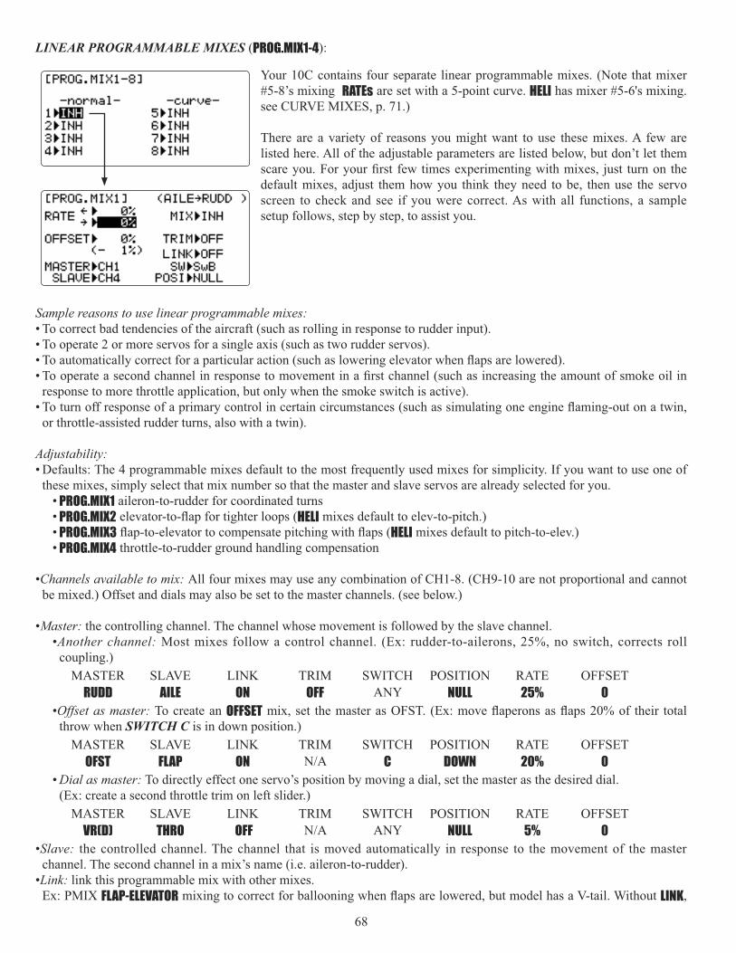
68
LINEAR PROGRAMMABLE MIXES (PROG.MIX1-4):
Sample reasons to use linear programmable mixes: • To correct bad tendencies of the aircraft (such as rolling in response to rudder input). • To operate 2 or more servos for a single axis (such as two rudder servos).
response to more throttle application, but only when the smoke switch is active).
or throttle-assisted rudder turns, also with a twin).
Adjustability:• Defaults: The 4 programmable mixes default to the most frequently used mixes for simplicity. If you want to use one of
these mixes, simply select that mix number so that the master and slave servos are already selected for you. • PROG.MIX1 aileron-to-rudder for coordinated turns• PROG.MIX2 HELI mixes default to elev-to-pitch.) • PROG.MIX3 HELI mixes default to pitch-to-elev.)• PROG.MIX4 throttle-to-rudder ground handling compensation
•Channels available to mix: All four mixes may use any combination of CH1-8. (CH9-10 are not proportional and cannot be mixed.) Offset and dials may also be set to the master channels. (see below.)
•Master: the controlling channel. The channel whose movement is followed by the slave channel. •Another channel: Most mixes follow a control channel. (Ex: rudder-to-ailerons, 25%, no switch, corrects roll
coupling.)MASTER SLAVE LINK TRIM SWITCH POSITION RATE OFFSET
RUDD AILE ON OFF ANY NULL 25% 0•Offset as master: To create an OFFSET
throw when SWITCH C is in down position.)MASTER SLAVE LINK TRIM SWITCH POSITION RATE OFFSET
OFST FLAP ON C DOWN 20% 0• Dial as master: To directly effect one servo’s position by moving a dial, set the master as the desired dial.
(Ex: create a second throttle trim on left slider.)MASTER SLAVE LINK TRIM SWITCH POSITION RATE OFFSET
VR(D) THRO OFF ANY NULL 5% 0•Slave: the controlled channel. The channel that is moved automatically in response to the movement of the master
channel. The second channel in a mix’s name (i.e. aileron-to-rudder). •Link: link this programmable mix with other mixes.
Ex: PMIX FLAP-ELEVATOR LINK,
Your 10C contains four separate linear programmable mixes. (Note that mixer #5-8’s mixing RATEs are set with a 5-point curve. HELI has mixer #5-6's mixing. see CURVE MIXES, p. 71.)
There are a variety of reasons you might want to use these mixes. A few are listed here. All of the adjustable parameters are listed below, but don’t let them
default mixes, adjust them how you think they need to be, then use the servo screen to check and see if you were correct. As with all functions, a sample setup follows, step by step, to assist you.

69
LINK ON, mixing is applied to both CH2 and CH4. MASTER SLAVE LINK TRIM SWITCH POSITION RATE OFFSET
FLAP ELEV ON OFF ANY NULL 5% 0•Trim: master’s trim affects slave. Not displayed if master is not CH 1-4, because 5-9 have no trim. Ex: two rudder servos.
With TRIM OFF, rudder trim would bind the two servos. TRIM ON resolves this. • On/off choices:
• SWITCH: Any of the positions of any of the 8 switches may be used to activate a mix. Up&Cntr, Cntr&Dn options allow the mix to be ON in 2 of the 3 positions of a 3-position SWITCH.
• NULL: No SWITCH can turn this mix OFF. This mix is active at all times. • LOGIC SW (Lsw1 to 3) may be assigned. Set up LOGIC SW: See p. 38.• STk-THR THROTTLE STICK OFST-to-(gear
doors) mix to open gear doors at idle, which is only active if throttle is below half.MASTER SLAVE LINK TRIM SWITCH POSITION RATE OFFSET
OFST AUX2 OFF NO STK-THR Stick at 1/2,for 1 sec.
100% 0
• Rate: the percentage of the slave’s range it will move upon maximum input from the master channel. Ex: RUDDER-AILERON
MASTER SLAVE LINK TRIM SWITCH POSITION RATE OFFSET RUDD AILE OFF OFF ANY NULL 50% 0
• Offset: Offsets the slave’s center relative to the master. Ex: Smoke valve opens wider per throttle servo position when smoke SWITCH is ON. Smoke servo’s neutral is moved down from THROTTLE STICK center to the bottom.
MASTER SLAVE LINK TRIM SWITCH POSITION RATE OFFSET THRO AUX2 OFF OFF E DOWN 100% 100%

70
GOAL of EXAMPLE: STEPS: INPUTS:Set up a FLAP-ELEV mix:
ON when SWITCH C is in the down position.
up (spoilers),
5% elevator movement when flaps move down,
LINK should be ON if model has twin e levator servos . Otherwise , L I N Kremains OFF.
(Flap has no trim lever, so TRIM is not an option.)
Open an unused programmable mix.(Ex: use PROG.MIX3 since it is already set-up for FLAP-ELEVATOR.)
for 1 second. (If BASIC, again.)
C to PROG.MIX-.C to 3 >.
Activate the function. C to MIX. to ON.Choose master and slave channels.(Ex: no need to change MASTER/SLAVE.)
already CH6
already CH2
Optional: set Master as OFST or VR(A-E).See above for details.
C to MASTER. to desired choice.
Set LINK and TRIM as needed.(Ex: leave LINK OFF, TRIM not available.)Assign SWITCH and position.(Ex: change from E to C, DOWN.)
C to SW. to C.C to POSI. to DOWN.
Optional: set switch to STk-THR to activate mix with THROTTLE STICK.(See above for details.)
C to SW. to STk-THR.C to POSI.
THROTTLE STICK to desired point.
for 1 second to set.Optional: set switch position to NULL.Makes mix active at all times. Not compatible with STk-THR.
C to POSI. to NULL.
Set rates. (Ex: Lo=0%, Hi=5%.) C to RATE.
VR(A) past center. Leave at 0%.
VR(A) past center. to 5%.Set OFFSET, if needed. (Ex: 0.) C to OFFSET. Leave at 0%.Close menu.
Where next? Adjust servo END POINTs: see p. 39.D/R,EXP): see p. 42.
Set up additional programmable mixes, ex: RUDDER-AILERON: see p. 68.View numerous additional mix setups: www.futaba-rc.com\faq\
Other Examples: • RUD-ELEV (ACRO GLID) mix: Compensate for pitching up or down when rudder is applied. • AIL-RUD mix (ACRO): Coordinate turns by applying rudder automatically with aileron input. All model types. • ELEV-PIT (HELI) mix: compensate for the loss of lift of tilting the model.

71
CURVE PROGRAMMABLE MIXES (PROG.MIX5-8)(HELI: PROG.MIX5-6 ):
Your 10C’s ACRO GLID programs contain four separate curve programmable mixes. HELI contains two. There are a variety
programmed curve mix is the THROTTLE-NEEDLE function. This curve is adjustable at 5 points, allowing you to adjust the motor’s tuning at 5 points along its RPM range.
One programmable curve mix defaults to RUDDER-AILERON. A linear mix that keeps the model from rolling in knife-edge is
mix. Inhibit the linear mix, then adjust the curve to get the right response all along the rudder channel’s travel.
• ACRO GLID Defaults: The 4 programmable curve mixes default to the most frequent choices, but can be set to any channel. • PROG.MIX5 rudder-to-aileron for roll coupling compensation (GLID mixes default to aileron-to-elev.) • PROG.MIX6 rudder-to-aileron for roll coupling compensation (GLID mixes default to aileron-to-elev.) • PROG.MIX7 rudder-to-elevator for pitch coupling compensation (GLID mixes default to elevator-to-airbrake.) • PROG.MIX8 rudder-to-elevator for pitch coupling compensation (GLID mixes default to elevator-to-airbrake.)
• HELI Defaults:• PROG.MIX5 aileron-to-elevator for coordinated turns • PROG.MIX6 aileron-to-elevator for coordinated turns
• Master: The controlling channel can only be a channel. Cannot be OFFSET or dial. • Trim: not available in curve mixes. • Offset: not available in curve mixes.

72
GOAL of EXAMPLE: STEPS: INPUTS:Set up a RUDD-ELEV curve mix on a model that pitches down severely at full rudder and not at all with minimal rudder input, and pitches worse on right rudder than left:
Point 1: 25%Point 2: 8%Point 3: 0%Point 4: 10%Point 5: 28%
ON when SWITCH C is down.
LINK should be ON if model has twin e levator servos . Otherwise , L I N Kremains OFF.
(Note that point 3 is 0%. Otherwise,the elevator would be retrimmed when the mix is active and no rudder input is given.)
Open an unused curve programmable mix. (Ex: use PROG.MIX7 since it is already set-up for RUDDER-ELEV.)
for 1 second. (If BASIC, again.)
C to PROG.MIX-.C to 7 >.
Activate the function. to page 2.C to MIX. to ON.
Choose master and slave channels.(Ex: do not change MAS or SLV).
already RUDD
already ELEV
Set LINK as needed. (Ex: off)Assign SWITCH and position.(Ex: change from F to C, DOWN.)
C to SW. to C.C to POSI. to DOWN.
Optional: set switch to STk-THR to activate mix with THROTTLE STICK.(See above for details.)
C to SW. to STk-THR.C to POSI.
THROTTLE STICK to desired point.
for 1 second to set.Optional: set switch position to NULL.Makes mix active at all times. Not compatible with STk-THR.
C to POSI. to NULL.
Set desired percent at the stick points. (Ex: listed at left.)
to page 1. C to POINT-1. to 25%.
Repeat for points 2-5.Close menu.
Where next? Adjust servo END POINTs: see p. 39.Set up AILEVATOR: see p. 57.Set up linear programmable mixes, ex: RUDDER-to-Aux2(twin rudder servos):see p. 68, or additional curve mix, ex: RUDDER-AILERON: see p. 71.View numerous mix setups: www.futaba-rc.com\faq\

73
GYA gyro mixing
GYA series gyros: GYA series gyros are a high performance, compact, and light weight AVCS gyro developed for model airplane. Integrated sensor and control circuit make it easy to mount. • GYA350: for airplane aileron, elevator, or rudder. • GYA351: for airplane ailerons, especially two servos such as when using FLAPERON.• GYA352: for airplane aileron, elevator, or rudder control. Two of these surfaces (axis) can be controlled by GYA352.
GYA series gyro operation modes: The GYA gyros have two operations modes: AVCS mode and Normal mode. • Normal mode: This mode performs general proportional control operation. For instance, it controls the gyro so that
changes are countered when the attitude of the aircraft is changed by cross-wind, etc. • AVCS mode: This mode performs both proportional and integrated control operation. The difference between Normal
mode and AVCS mode operation is that where as the Normal mode only counters changes in attitude, the AVCS mode returns to the original controlled variable simultaneously with countering changes in attitude. For example, during
performed automatically by the gyro.
Adjustability:• Plug the gyro's sensitivity adjustment to channel 5, 7, or 8 of the receiver.
(selectable)• Full switch assignability (SWITCH A-H)• Each rate setting may be set from 0 to NOR100% or AVC100% gain.
NOR: Normal mode gain. AVC: AVCS mode gain • Larger percentages indicate more gain, or gyro responsiveness. • MIX-1,2: Two surfaces' sensitivity can be adjusted independently.
Gyro gain adjustment: • When the servo hunts, the gyro gain is too high. Lower the gain until the hunting stops.
repeatedly.
Precautions: • When taking off and landing, always switch to the Normal mode. Taking off and landing in the AVCS mode is dangerous. • We recommend that you use the rudder control gyro in the Normal mode. In the AVCS mode, rudder operation is
necessary when turning because the weathervane effect is lost. Use the gyro in the Normal mode unless you are an expert in rudder operation.
• And we recommend that you also set to off (0%) mode for safety as follows.
GOAL of EXAMPLE: STEPS: INPUTS:Set up a GYA gyro setting. (Ex: MIX-1) Open and activate the GYRO SENSE
function.for 1 second. (If BASIC, again.)
C to GYRO SENSE.Activate the function. C to MIX-1. to ON.Optional: change switch assignment. Ex: select E.
C to SW
to E.Adjust gyro rates as needed. (Ex:UP to NOR70%, CNTR to 0% (off), DOWN to AVC70% as starting points.)
C to gyro rate
E up. to NOR 70%.
(0%).
E down. to AVC 70%.Close menu.

74
Special Additions, Functions, And Added Equipment Commonly Used On Powered Aircraft
Gyros: model every time throttle is applied. For many years gyroscopes have been used on model helicopters to control this. In competition aerobatics and scale aircraft competition alike, the usefulness of gyros has recently come to light. For in-depth information on gyro types, please see p. 106.
offers a twin-axis gyro, GYA-352, that controls two axes with a single gyro.) For 3D aerobatics (below stall speed, such as
gyros are frequently used to simplify take-offs and landings by keeping the model straight during throttle application.
Retracts: Retractable landing gear is often used on scale models for increased realism and on high performance models to decrease drag. The gear servo is typically plugged into CH5, which defaults to a 2-position switch for simplicity.
Mechanical retracts require the use of a specialized non-proportional retract servo. Retract servos go from full travel one direction to full travel the other direction, then mechanically hold the gear into the locked position. A regular servo used for mechanical retracts will continue to draw full power the entire time, prematurely draining the battery and risking crash of your model. End point will not adjust a retract servo.
Pneumatic (air driven) retracts use a standard servo to control an air valve which directs air into or out of the retract units, moving the gear up or down. Pneumatics are easier to install but require added maintenance of the air system.
Gear Doors: Some scale models with retracts also have separate gear doors to cover the scale gear. For one example of how to operate the gear doors separately from the retracts, please visit our website: www.futaba-rc.com\faq\.
Smoke Systems: Many scale and aerobatic models use smoke systems to provide increased realism or a more impressive
It is a good practice to set up a "safety" that shuts off the smoke oil if the throttle is lowered below half-stick. For a detailed example of a smoke system setup, please visit our website: www.futaba-rc.com\faq\.
Kill Switches: For safety reasons, it is strongly recommended that an electronic kill switch be installed in all gasoline-
Lastly, an electronic kill switch set to "off" prior to the aircraft's power being shut off adds an additional safety should someone accidentally turn on the mechanical kill switch on the exterior of the model.
Bomb Drops, Paratroopers, and other Released Items: Many sport and scale models include one or more of these fun add-ons. Typically, all are controlled by a simple micro-switch plugged into CH9 or CH10. The switch is assigned in AUX-CH.

75
GLIDER MODEL FUNCTIONS Please note that nearly all of the BASIC menu functions are the same for airplane (ACRO setup), sailplane (GLID 1A+1F2A+1F 2A+2F setups), and helicopter (HELI setups). The features that are identical refer back to the ACRO chapter. The glider BASIC menu includes MOTOR CUT and does not include IDLE-DOWN or THR-CUT.
Note that in all cases where ACRO programming labels channel 3 as throttle, GLID programming labels channel 3 as ARB(airbrake), since airbrakes are normally operated on channel 3 in gliders. This includes STK-THR reading STK-ARB.
GLIDER (GLID(1A+1F) (2A+1F) (2A+2F)) FUNCTIONS . 75 Table of contents........................................................ 75 Getting Started with a Basic 4-CH Glider ................ 76
GLIDER BASIC MENU FUNCTIONS .......................... 78 MOTOR CUT ................................................................ 79MODEL Submenu: MODEL SELECT, COPY, NAME .......... 30 PARAMETER Submenu: RESET, MODUL, ATL, AILE-2,CONTRAST, BACK-LIGHT, USER NAME, LOGIC SW ........ 33Model type (PARAMETER submenu) ........................... 78Servo REVERSE ........................................................... 38END POINT .................................................................. 39
D/R, EXP) .......... 42TIMER Submenu.......................................................... 45Auxiliary Channel assignments and CH9 reverse (AUX-CH) ............................................................................. 46TRAINER ..................................................................... 47TRIM and SUB-TRIM ................................................... 48SERVO Display ........................................................... 49Fail Safe and Battery FailSafe (F/S) ......................... 50
GLIDER ADVANCE MENU FUNCTIONS ..................... 80 FLAPERON ................................................................... 52FLAP TRIM .................................................................. 53Aileron Differential (AILE-DIFF) ................................. 54ELEVON (see tail types) ............................................... 56ELEVON ....................................................................... 56V-TAIL ......................................................................... 58Linear, Prog. mixes 1-4 ............................................. 68Curve, Prog. mixes 5-8 ............................................. 71ELEV-FLAP .................................................................... 62BUTTERFLY (modifyed version of AIRBRAKE) ............. 63BUTTERFLY................................................................... 87 AILE/RUDD .................................................................. 81AILE-FLAP (GLID(2A+2F) only) .................................... 82SPOILER MIX ............................................................... 83OFFSETs ...................... 84START DELAY (GLID(1A+1F) only) ................................. 85CAMBER MIX ............................................................... 85 CAMBER FLAP .............................................................. 86Channel 3’s function selection (CONDITION/FUNCTION) 88
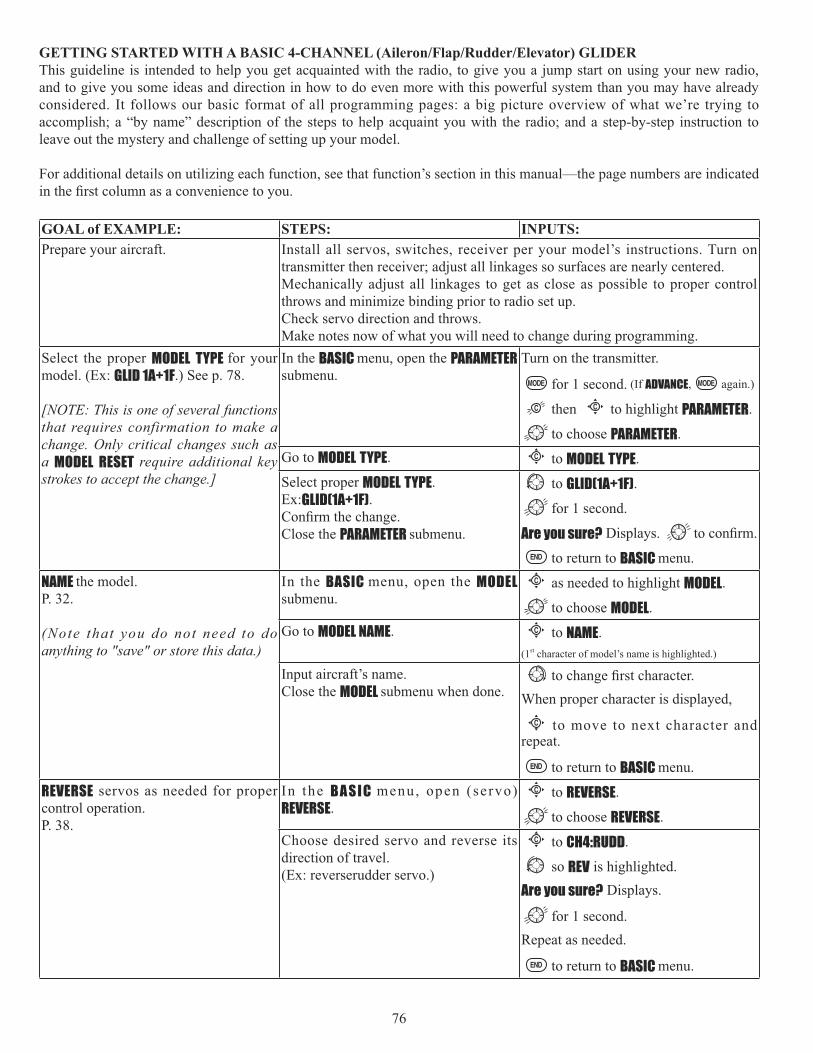
76
GETTING STARTED WITH A BASIC 4-CHANNEL (Aileron/Flap/Rudder/Elevator) GLIDER This guideline is intended to help you get acquainted with the radio, to give you a jump start on using your new radio, and to give you some ideas and direction in how to do even more with this powerful system than you may have already considered. It follows our basic format of all programming pages: a big picture overview of what we’re trying to accomplish; a “by name” description of the steps to help acquaint you with the radio; and a step-by-step instruction to leave out the mystery and challenge of setting up your model.
For additional details on utilizing each function, see that function’s section in this manual—the page numbers are indicated
GOAL of EXAMPLE: STEPS: INPUTS:Prepare your aircraft. Install all servos, switches, receiver per your model’s instructions. Turn on
transmitter then receiver; adjust all linkages so surfaces are nearly centered.Mechanically adjust all linkages to get as close as possible to proper control throws and minimize binding prior to radio set up.Check servo direction and throws.Make notes now of what you will need to change during programming.
Select the proper MODEL TYPE for your model. (Ex: GLID 1A+1F.) See p. 78.
[NOTE: This is one of several functions that requires confirmation to make a change. Only critical changes such as a MODEL RESET require additional key strokes to accept the change.]
In the BASIC menu, open the PARAMETER submenu.
Turn on the transmitter.
for 1 second. (If ADVANCE, again.)
then C to highlight PARAMETER.
to choose PARAMETER.Go to MODEL TYPE. C to MODEL TYPE.Select proper MODEL TYPE.Ex:GLID(1A+1F).
Close the PARAMETER submenu.
to GLID(1A+1F).
for 1 second.
Are you sure? Displays.
to return to BASIC menu.
NAME the model.P. 32.
(Note that you do not need to do anything to "save" or store this data.)
In the BASIC menu, open the MODEL submenu.
C as needed to highlight MODEL.
to choose MODEL.Go to MODEL NAME. C to NAME.
(1st character of model’s name is highlighted.)
Input aircraft’s name.Close the MODEL submenu when done. When proper character is displayed,
C to move to next character and repeat.
to return to BASIC menu.
REVERSE servos as needed for proper control operation.P. 38.
In the B A S I C menu, open (servo) REVERSE.
C to REVERSE.
to choose REVERSE.Choose desired servo and reverse its direction of travel. (Ex: reverserudder servo.)
C to CH4:RUDD.
so REV is highlighted.
Are you sure? Displays.
for 1 second.Repeat as needed.
to return to BASIC menu.

77
GOAL of EXAMPLE: STEPS: INPUTS:Adjust travels as needed to match model’s recommended throws (usually listed as high rates).P. 39.
In the BASIC menu, choose END POINT. C to END POINT.
to choose END POINT.Adjust the servos’ end points.
Close the function.
C to FLAP.
VR(A) until travel as desired.
VR(A). Repeat as needed.
(D/R,EXP)P. 42.
(Note that in the middle of the left sideof the screen is the name of the channel and the SWITCH position you are adjusting. Two or even three rates maybe set per channel by simply choosing the desired SWITCH and programming percentages with the SWITCH
Choose D/R,EXP. C to D/R,EXP.
to choose D/R,EXP.Choose the desired control, and set the first (Ex: high) rate throws and exponential.
C to CH>.
to choose CH>2 (elevator).
A to up position. [Note screen reads ELEV
(UP)]
C to D/R.
ELEVATOR STICK. to set.
ELEVATOR STICK. to set.(Normally the same for both directions.)
C to EXP.
ELEVATOR STICK. to set.
ELEVATOR STICK. to set.Set the second (low) rate throws and exponential.
C to D/R. A to down position.Repeat above to set low rate.
Optional: change dual rate SWITCHassignment. Ex: elevator to SWITCH Gwith 3 positions.
C to SW. to G.
G to center position.Repeat steps above to set 3rd rate.
to the left slider [VR(D)]. (AUX-CH)p. 46.
In the BASICmenu, open AUX-CH. C to AUX-CH. to choose AUX-CH.Choose CH6Change primary control to VR(D).Change other channels as needed.
C to CH6.
to VR(D).Repeat as required.
Return to the home screen.
Where next? (Other functions you may wish to set up for your model.)TRAINER p. 47.Multiple wing or tail servos. See wing types and tail types: p. 51, 56.OFFSETS, BUTTERFLY(AIRBRAKERetractable Gear, Smoke systems, kill switches, and other auxiliary channel setups: p. 46.Adjusting SUB-TRIMs to match servo centers: p. 49.

78
GLID-SPECIFIC FUNCTIONS STEP BY STEP. Those functions which are identical to the ACRO setups are referred directly to those pages.
MODEL TYPE: This function of the PARAMETER submenu is used to select the type of model programming to be used.
GLIDER TYPES:
MODEL TYPE• ACRO ACRO is a better choice because of functions it offers that the GLID types do not.
• ACRO provides: • SNAP-ROLL,• AILEVATOR (twin elevator servo support), • AIRBRAKE (a more assignable version of BUTTERFLY).• For nitro-powered sailplanes: IDLE-DOWN, THR-CUT, THROTTLE-NEEDLE mixing and THROTTLE DELAY programming.
• But ACROStart, Speed, Distance and Landing.
• GLID(1A+1F): The GLID(1A+1F) MODEL TYPE is intended for sailplanes with one or two aileron servos (or none), and a single TYPE is meant to be a very simplistic version to set up a basic
• GLID(2A+1F): The GLID(2A+1F) MODEL TYPE
trims and aileron differentials to make the sailplane perform certain maneuvers more easily.• GLID(2A+2F): The GLID(2A+2F) MODEL TYPE supports dual flap servos that can also act as ailerons, creating full-span
differentials to make the sailplane perform certain maneuvers more easily.
GOAL of EXAMPLE: STEPS: INPUTS:Change model1 is MODEL T YPE to GLID(1A+1F).
NOTE: This is one of the several funct ions that the radio requires
Confirm you are currently using the proper model memory. (Ex: 1)
On home screen, check model nameand number on top left.
If it is not the correct model (Ex: 1), use MODEL SELECT, p. 25.
Open PARAMETER submenu. for 1 second. (If ADVANCE, again.)
to 2nd page of menu.C to PARAMETER.
Change the MODEL TYPE. C to TYPE. to GLID(1A+1F).
for one second.
Are you sure?
Close.
GLID(1A+1F)(FLAPERON)
AIL1FLP2(CH1)
AIL2FLP1(CH6)
AIL1(CH1)
AIL2(CH7)
FLP(CH6)
GLID(2A+1F)
AIL1(CH1)
FLP1(CH6)
FLP2(CH5)
AIL2(CH7)
GLID(2A+2F)

79
Motor cut function (MOTOR CUT) (GLIDAIRBRAKE STICK position. The servo movement is largest at -30%.
The switch's location and direction must be chosen. It defaults to NULL to avoid accidentally assigning it to a switch, which might result in an unintentional dead
Adjustability:• RATE range of -30 to +30. The servo movement at 0% is maximum slow position of AIRBRAKE STICK. The servo
movement is largest at -30%. • SWITCH A-H fully assignable. Also LOGIC SW (Lsw1 to 3) may be assigned.• POSITION fully assignable, including NULL (mix always off) and Up&Cntr and Cntr&Dn to activate the mix in 2 separate
positions of the same SWITCH.
GOAL of EXAMPLE: STEPS: INPUTS:Decrease the rate to stop the motor
MUST assign a switch. The default is NULL.)
Open BASICmenu, then open THR-CUTfunction.
for 1 second. (If ADVANCE, again.)
C to THR-CUT.Activate the function. Choose desired switch, and the position which activates the function.
C to MIX. to OFF or ON.C to SW. to desired switch.C to POSI. to desired position.C to RATE. until turns off.
Close.
Where next? D/R,EXP): see p. 42.Set up TRAINER functions: see p. 47.Set up twin aileron servos: see p. 51.Set up twin elevator servos: see p. 57.
*Also LOGIC SW(Lsw1 to 3) may be assigned. Set up LOGIC SW: See p. 38.

80
GLIDER ADVANCE MENU
Varied wing types and tail types (twin aileron servos, twin elevator servos, elevon, v-tail, etc). See p. 51-58 for basic information.
• FLAPERON (GLID 1A+1Fp. 45.
• CAMBER FLAP• For sailplanes, this function is also used as wing camber. The amount depends on the model, but usually a small
amount (less than 10%) is preferred, since too much camber produces excess drag. Don’t use more than about
camber. Be sure to consult your model’s manual for guidelines. • Note that even though you may make CAMBER FLAP active while using AILE-DIFF, it will not have any effect. The
AILE-DIFF• Aileron Differential (AILE-DIFF): allows twin aileron servos to provide differential down travel from up travel. See p.
54.• Using a 5-channel receiver with FLAPERON and AILE-DIFF. See AIL-2, p. 55. • ELEVON• V-TAIL: for models with 2 servos operating together to create roll and pitch control. See p. 58. • AILEVATOR: not available in GLID model types.
Mixes:• Linear Programmable mixes (PROG.MIX1-4): fully assignable programmable mixes with a linear response. see p. 68. • Curved Programmable mixes (PROG.MIX5-8): fully assignable programmable mixes with a curved response. See p.
71.• ELEV-FLAP• BUTTERFLY: Often called crow, BUTTERFLY is the glider version of AIRBRAKE. (BUTTERFLY does not have the option to
activate it solely from a switch, and its activation switch. It always provides progressively more BUTTERFLY as the CHANNEL 3 (THROTTLE) STICK is lowered, or raised if used THR-REV, p.38.) See AIRBRAKE, p. 63.
Full Span Mixing: Flap-to-Aileron and Aileron-to-Flap• CAMBER-MIX AILE-FLAP
themselves.NOTE: When you have ELEV-FLAP mixing also, the trailing edge droops with the elevators, increasing pitch response.

81
AILE RUDD(GLID):
Adjustability:• RATE range of -100 to +100. Negative setting would result in opposite rudder (aileron) action from aileron (rudder). • SWITCH A-H fully assignable. Also LOGIC SW (Lsw1 to 3) may be assigned. Set up LOGIC SW: See p. 38.• POSITION fully assignable, including NULL (mix always on) and Up&Cntr and Cntr&Dn to activate the mix in 2 separate
positions of the same SWITCH.• Condition: The separate AILE RUDD
GOAL of EXAMPLE: STEPS: INPUTS:
corrects roll coupling.Open AILE RUDD mix submenu. for 1 second. (If BASIC, again.)
to 2nd page of menu.C to AILE RUDD.
Select the mixing mode. C to MODE. to RUDD AILE
Activate the function. C to MIX to ON.Set the rate. (Ex: 100% each way) C to FLP1.
RUDDER STICK. to +25%.
RUDDER STICK. to +25%.Repeat as needed.Close.
Where next? ELEV-FLAP mixing. See p. 62.BUTTERFLY. See p. 63.Use a mix to OFFSETView additional model setups on the internet: www.futaba-rc.com\faq\
You can select a pre-programed mix which is used to mix the rudders with aileron operation or the ailerons with rudder operation.Aileron-to-rudder mix (AILE RUDD): automatically creates a "coordinated turn". Rudder -to-aileron mix (RUDD AILE): used to counterract undesirable roll (roll coupling) that happens with rudder input, especially in knife-edge.

82
AILE-FLAP(GLID 2A+2F only):
Adjustability:• RATE• SWITCH A-H fully assignable. Also LOGIC SW (Lsw1 to 3) may be assigned. Set up LOGIC SW: See p. 38.• POSITION fully assignable, including NULL (mix always on) and Up&Cntr and Cntr&Dn to activate the mix in 2 separate
positions of the same SWITCH.• Condition: The separate AILE-FLAP
GOAL of EXAMPLE: STEPS: INPUTS:Turn on AILE-FLAP mixing. Set rate to100% for maximum possible flap travel with ailerons. Assign to SWITCHC center.
Open AILE-FLAP submenu. for 1 second. (If BASIC, again.)
to 2nd page of menu.C to AILE-FLAP.
Activate the function. C to MIX to ON.Set the rate. (Ex: 100% each way) C to FLP1.
AILERON STICK. to +100%.
AILERON STICK. to +100%.Repeat above to set FLP2.
Assign the SWITCH and position. C to SW. to C.C to POSI. to CENTER.
Close.
Where next? ELEV-FLAP mixing. See p. 62.BUTTERFLY. See p. 63.Use a mix to OFFSETView additional model setups on the internet: www.futaba-rc.com\faq\
This pre-programmed mix is used to create full span aileron action on a glider with 4wing servos. This increases the roll rate and decreases induced drag.
models in speed runs, you may wish to use a larger value approaching 100%.

83
SPOILER MIX (GLID SPOILERMIX works linking with BUTTERFLY function.
Adjustability:• Position: -100% to +100%, with a default of -50% (off), +50% (on)• Channel: Spoiler 1: ch8, 5 or 3 (ch8 or 3*), Spoiler 2: NULL, ch5 or 3 (NULL or ch3*) *GLID (2A+2F) mode
• Elevator setting: Rate: -100% to +100%, Delay: 0% to 100%• SWITCH A-H fully assignable. Also LOGIC SW (Lsw1 to 3) may be assigned. Set up LOGIC SW: See p. 38.
GOAL of EXAMPLE: STEPS: INPUTS:2-servo spoiler mode. Adjust the spoiler servo position to 60%.
Open the SPOILER MIX function and move to 2nd page.
for 1 second. (If BASIC, again.)C to SPOILER MIX.
to 2nd page.Activate the function. C to MIX. to ON.Assign the SPO2-CH. (Ex: CH3) C to SPO2-CH. to CH3.Adjust the spoiler servo position. (Ex: SPO1 SPO2=+55% to +60%)
C to +50%. (SPO1) to +60%.C to +50%. (SPO2) to +60%.
Optional: Set the elevator rate. (EX: 10%)
C to rate-ELE. to 10%.
Optional: Set the delay. (EX: 25%) C to dly-ELE. to 25%.Close menu.
Where next? Set up BUTTERFLY mixing: see p. 87.
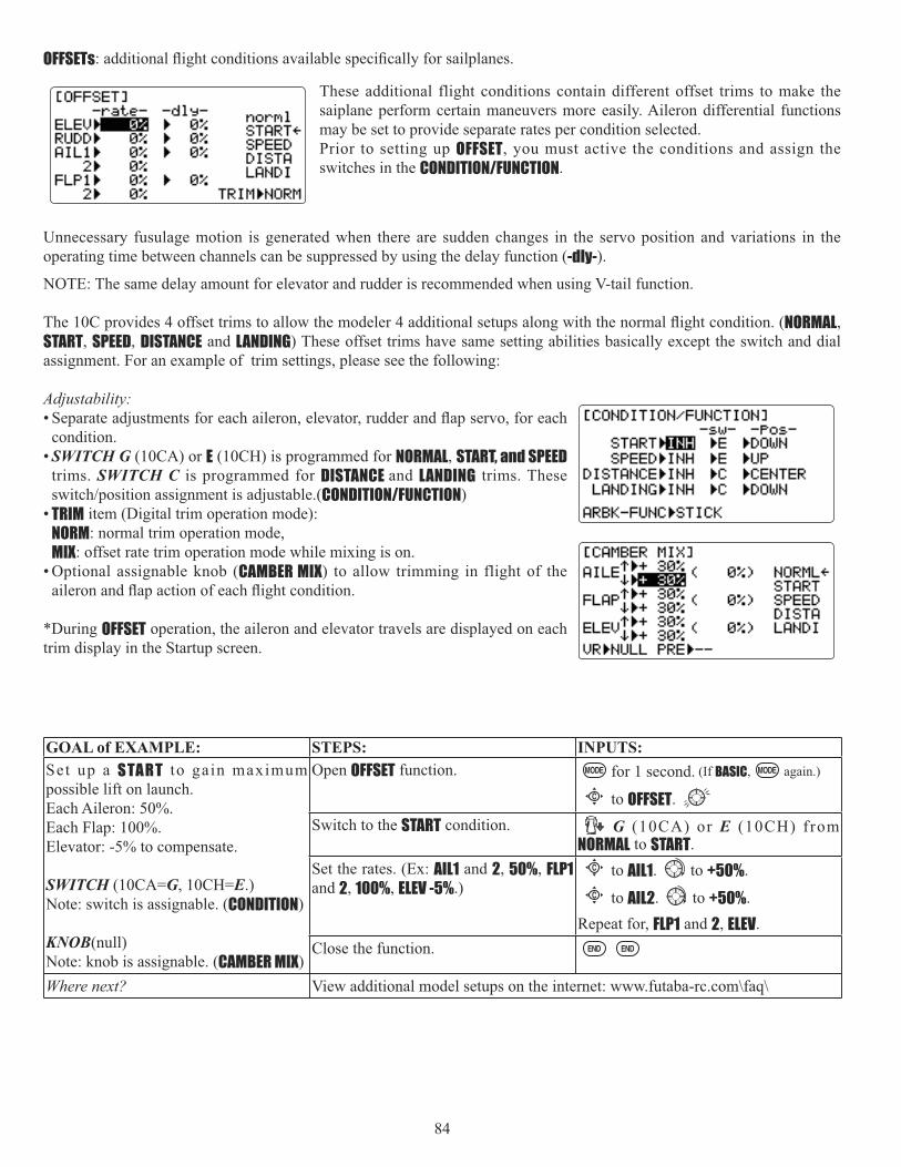
84
OFFSETs
Unnecessary fusulage motion is generated when there are sudden changes in the servo position and variations in the operating time between channels can be suppressed by using the delay function (-dly-).
NOTE: The same delay amount for elevator and rudder is recommended when using V-tail function.
NORMAL,START, SPEED, DISTANCE and LANDING) These offset trims have same setting abilities basically except the switch and dial assignment. For an example of trim settings, please see the following:
Adjustability:
condition.• SWITCH G (10CA) or E (10CH) is programmed for NORMAL, START, and SPEED
trims. SWITCH C is programmed for DISTANCE and LANDING trims. These CONDITION/FUNCTION)
• TRIM item (Digital trim operation mode): NORM: normal trim operation mode, MIX: offset rate trim operation mode while mixing is on.
• Optional assignable knob (CAMBER MIX) to allow trimming in flight of the
*During OFFSET operation, the aileron and elevator travels are displayed on each trim display in the Startup screen.
GOAL of EXAMPLE: STEPS: INPUTS:Set up a START to gain maximum possible lift on launch. Each Aileron: 50%.Each Flap: 100%.Elevator: -5% to compensate.
SWITCH (10CA=G, 10CH=E.)Note: switch is assignable. (CONDITION)
KNOB(null)Note: knob is assignable. (CAMBER MIX)
Open OFFSET function. for 1 second. (If BASIC, again.)
C to OFFSET.Switch to the START condition. G (10CA) or E (10CH) from
NORMAL to START.Set the rates. (Ex: AIL1 and 2, 50%, FLP1and 2, 100%, ELEV -5%.)
C to AIL1. to +50%.C to AIL2. to +50%.
Repeat for, FLP1 and 2, ELEV.Close the function.
Where next? View additional model setups on the internet: www.futaba-rc.com\faq\
These additional flight conditions contain different offset trims to make the saiplane perform certain maneuvers more easily. Aileron differential functions may be set to provide separate rates per condition selected. Prior to setting up OFFSET, you must active the conditions and assign the switches in the CONDITION/FUNCTION.

85
Camber Mixing (CAMBER MIX)(GLID):
This function adjusts the mixing rate of camber operation which operates the
changes caused by camber operation can be corrected.Also the operation reference point of camber control can be offset. (PRE)
NOTE: Camber control is not assigned at initial.
GOAL of EXAMPLE: STEPS: INPUTS:Ex: Set the mixing amount for aileron to 40%, camber control to VR(E) ,reference point to desired point.
Open the CAMBER MIX function. for 1 second. (If BASIC, again.)
C to CAMBER MIX.Choose desired slider. C to VR. to VR(E).Adjust the mixing amount for AILE.(Ex: adjust to 40%.)
C to AILE. VR(E). to 40%.
VR(E). to 40%.Set the reference point. C to PRE. or VR(E) to
desired point. for one second.Close menu.
Adjustability:• Rate: -100% to +100%, with a default of +30%• Reference point (PRE): The operation reference point of camber control can be offset. -100% to +100%, with a default of 0%.
START DELAY (GLID 1A+1F only):
START DELAY automatically switch the offset trims (OFFSET) from the STARTcondition's trims to the normal cndition's trims after proceeding the delay time (max.10sec.) which is set by the -dly- item when activating the START condition. (It is convenient for hand launch glider.)
NOTE: The same delay amount for elevator and rudder is recommended when using V-tail function.
Adjustability:• Delay time (-dly-) range of 0 to 100%. The delay time is 10 second at 100%.
GOAL of EXAMPLE: STEPS: INPUTS:Ex: delay time=5 second. Open ADVANCE menu, then open START
DELAY function.for 1 second. (If ADVANCE, again.)
C to START DELAY.Activate the function. C to MIX. to OFF or ON.Set the delay time. (Ex: 50% each surface)
C to ELEV. to 5O%.C to RUDD. to 5O%.
Repeat as needed.Close.

86
Flap Setting (CAMBER FLAP)(GLID):
CAMBER FLAP assigns the primary flap control [defaults to VR(A)] to allow
FLP1 2) can be adjusted
NOTE: If FLAP-TRIM is activated, you can not use CAMBER FLAP function simultaneously.
[Note] When changing the polarity of a rate, "change rate dir?" is displayed for a check. Please set up after pressing DIAL for 1 second and canceling an alarm display.
GOAL of EXAMPLE: STEPS: INPUTS:Ex: Set the maximum travel of 35% of Open the CAMBER FLAP function. for 1 second. (If BASIC, again.)
C to CAMBER FLAP.
separately. (Ex: adjust to 35%.)
C to FLP1. VR(A). to 35%.
VR(A). to 35%. Repeat.
Option: Adjust the center position of C to CENTER. to desired point.
Close menu.
Adjustability:• Rate: -100% to +100%, with a default of +30%• Center position (CENTER

87
BUTTERFLY (crow) mixing (GLID):
BUTTERFLY (often called "crow"- see GLIDand is usually used to make steep descents or to limit increases in airspeed in dives. Separate two BUTTERFLY settings are available. (CIR1 CIR2)
Adjustability:• Activation: Proportional by moving the THROTTLE STICK.• Switch: Mix SWITCH is selectable.
A to H: SWITCH A to HNULL: always on. Also LOGIC SW (Lsw1 to 3) may be assigned. Set up LOGIC SW: See p. 38.
• Inversely proportional to THROTTLE STICK: provides a proportional increase in amount of airbrake action as THROTTLE STICK is lowered (when SWITCH A (assignable) is in down position). Includes selectable stick position where airbrake begins. If you would like to have the airbrake be directly proportional to throttle stick, you will need to reverse the THR-REV function. Note that this changes the throttle stick direction for all models. See page 38 for instructions.
• Elevator settings: (adjustable in the B.FLY-ELE)B.FLY-ELE works linking with BUTTERFLY function. Elevator rate is adjustable in a 3 point curve. Point 1: PRESET point. (Fixed)Point 2: MID point. Position and rate are adjustable.Point 3: END point. Position and rate are adjustable.
• Delayed reaction: You can suppress sudden changes in your model's attitude when BUTTERFLY is activated by setting the delay (DELAYpoint together. A setting of 100% slows the servo to take approximately one second to travel the prescribed distance.
• Channels controlled: BUTTERFLY, including set to 0 to have no effect.
• Twin aileron servos: If AIL-DIFF function is inhibited, then AIL1 and AIL2 settings will have no effect. • If AIL-DIFF is active, then CH1 and CH7 may be independently adjusted. • Normally both ailerons are raised equally in BUTTERFLY, and the elevator motion is set to maintain trim when the ailerons
rise. Different amounts may be set for each aileron to correct for torque reactions and other unique characteristics of the model.
Be sure you understand what dropping ailerons will do when in BUTTERFLY. Along with creating an enormous amount of drag (desireble for spot landings), this also creates "wash-in", a higher angle of attack where the ailerons are, and encourages tip stalling. If you are using this for aerobatic performance and not "sudden stops", consider raising the

88
GOAL of EXAMPLE: STEPS: INPUTS:Activate BUTTERFLY.Adjust the aileron and flap travel to 75%.
Elevator settings are adjustable in the B.FLY-ELE.
Mix switch is selectable.
Open the BUTTERFLY function. for 1 second. (If BASIC, again.)
C to BUTTERFLY.Activate the function. SWITCH A in up position.
C to MIX to OFF.Adjust the travels as needed. (Ex: Ailerons each 75%, Flap 75%.)
C to AIL1 to 75%.C to FLAP to 75%.C to AIL2 to 75%.
Close menu.
Where next? View additional model setups on the internet: www.futaba-rc.com\faq\
Channel 3's function selection (CONDITION/FUNCTION):
Channnel 3's function is selectable in the ARBK-FUNC item. (Throttle stick, switches, or knobs)By choosing except STK, channel 3's function may be separated from BUTTERFLY's function, so channel 3 can be used for other functions.
Adjustability:• Channel 3's function:
STK: THROTTLE STICKSw-A to H: SWITCH A to HVr-A to Vr-E: KNOB A to E

89
HELICOPTER MODEL FUNCTIONS
Please note that nearly all of the BASIC menu functions are the same for airplane (ACRO setup), sailplane (GLID setups), and helicopter (HELI) setups. The features that are identical refer back to the ACRO chapter. The Helicopter BASIC menu includes the normal condition's throttle and collective pitch curves and revo. mixing. (idle-ups and throttle hold are advanced features and are in the ADVANCE menu).
HELICOPTER FUNCTIONS.......................................... 89Table of contents and reference info for helicopters . 89Getting Started with a Basic Helicopter ................... 90
HELI BASIC MENU FUNCTIONS .................................. 93MODEL Submenu: MODEL SELECT, COPY, NAME .......... 30 PARAMETER Submenu: RESET, MODUL, ATL, AILE-2,CONTRAST, BACK-LIGHT, HOME-DISP, USER NAME, LOGIC SW ............................................................................. 33MODEL TYPE (PARAMETERS submenu) ........................ 93Servo REVERSE ........................................................... 38SWASH AFR (swashplate surface direction and travelcorrection) (not in H-1) .............................................. 95THROTTLE MIX ............................................................ 96END POINT .................................................................. 39Setting up the Normal Flight Condition ................... 97THR-CUTmodels) ..................................................................... 98
D/R, EXP) .......... 42TIMER Submenu.......................................................... 45Auxiliary Channel assignments and CH9 reverse (AUX-CH) ............................................................................. 46TRAINER ..................................................................... 47TRIM and SUB-TRIM ................................................... 48SERVO Display ........................................................... 49Fail Safe and Battery FailSafe (F/S) ......................... 50
HELI ADVANCE MENU FUNCTIONS ............................. 99THROTTLE HOLD .......................................................... 99THR-CURVE, PIT-CURVE and REVO ............................. 100Idle-ups ................................................................... 101
............................................................. 102Delay ....................................................................... 103Hovering setups ...................................................... 104
........................................................ 105Gyros and governors ............................................... 106
..................................... 61Linear, Prog. mixes 1-4 ............................................. 68Curve, Prog. mixes 5-8 ............................................. 71THROTTLE-NEEDLE ........................................................ 65

90
GETTING STARTED WITH A BASIC HELICOPTER This guideline is intended to help you set up a basic (H-1) heli, to get acquainted with the radio, to give you a jump start on using your new radio, and to give you some ideas and direction on how to do even more with this powerful system than you may have already considered. It follows our basic format of all programming pages—a big picture overview of what we're trying to accomplish; a “by name” description of the steps to help acquaint you with the radio; and then a step-by-step instruction to leave out the mystery and challenge of setting up your model.
• Aileron: changes cyclic lateral (roll) . Rolls the helicopter. Tilts the swashplate to the left or right. CH1. • Elevator: changes cyclic pitch. Changes the helicopter’s angle of attack (nose up or nose down). Tilts the entire
swashplate fore and aft. CH2.• Rudder: changes the angle of the tail rotor. Yaws the helicopter left or right. CH4. • Collective Pitch: adjusts main rotor collective [angle of the paddles], changing the main blades’ pitch. Increased
collective pitch (with throttle) causes the helicopter to rise. Moves in conjunction with throttle on the THROTTLE STICK. CH6.
• Throttle: THROTTLE STICK. CH3. • REVO: mix that adds rudder in conjunction with pitch. This helps compensate for rotation of the helicopter caused by the
GOAL of EXAMPLE: STEPS: INPUTS:Prepare your helicopter. Install all servos, switches, receiver per your model's instructions. Set all trims,
dials and sliders to neutral.
horn to the ball link for proper geometry and that no slop is present.Mechanically adjust all linkages to get as close as possible to proper control throws and minimize binding prior to radio set up.
Select the proper MODEL TYPE for your model. Ex: HELI (H-1). See p. 93.
[ N O T E : T h i s i s o n e o f s e v e r a l functions for which the radio requires con f i rmat ion to make a change . Onlycritical changes require additional key strokes to accept the change.]
(If the correct model type was already displayed, be sure to do a model reset to discard any unwanted settings.)
In the BASIC menu, open the PARAMETER submenu.
Turn on the transmitter.
for 1 second. (If ADVANCE, again.)
then C to highlight PARAMETER.
to choose PARAMETER.Go to MODEL TYPE. C to TYPE.Select proper MODEL TYPE.Ex: HELI(H-1). Confirm the change. Close PARAMETER.
to HELICOPTER. for 1 second.
Are you sure? displays. C to SWASH.
to H-1. for 1 second.
Are you sure? displays.
to return to BASIC menu.Then, NAME the model. P. 32.
(You do not need to do anything to “ save” or store this data.)
In the BASIC menu, open the MODEL submenu.
C as needed to highlight MODEL.
to choose MODEL.Go to MODEL NAME. C to NAME.
(First character of model'sname is highlighted.)
Input aircraft's name.
Close the MODEL submenu when done.When proper character is displayed,
C to move to next character.
Repeat. to return to BASIC menu.

91
GOAL of EXAMPLE: STEPS: INPUTS:Reverse servos as needed for proper control operation. Ex: LEFT RUDDER STICK results in leading edge of tail rotor blades moving left. Reverse to operate properly. P. 38.
In the BASIC menu, open REVERSE. C to REVERSE.
to choose REVERSE.Choose desired servo and reverse its direction of travel. (Ex: reverse rudder servo.)
C to CH4:RUDD.
so REV is highlighted.
Are you sure? Displays.
for 1 second.Repeat as needed.
to return to BASIC menu.Adjust Travels as needed to match model's recommended throws (usually listed as high rates).P. 39.
In the BASIC menu, choose END POINT. C to END POINT.
to choose END POINT.Adjust the servos’ end points.(Ex: elevator servo)
Return to BASIC menu.
C to ELEV.
ELEVATOR STICK.
until up travel is as desired.
ELEVATOR STICK.
until down travel is as desired.
Repeat as needed. Activate THR-CUT. P. 98. Open THROTTLE-CUT function. C to THROTTLE-CUT.
to choose THR-CUT.Activate the function. Choose desired switch and position to activate.
C to MIX to OFF.C to SW. to C.C to POSI. to DOWN.
With THROTTLE STICK at idle, adjust the rate until the engine consistently shuts off, but throttle linkage is not binding.1
Close.
C to down position.
THROTTLE STICK.C to RATE. until shuts off.
Set up throttle curve for normal.2(Usually changes will not need to be
Open the THR-CURV/NOR function. Adjust if needed. Close the function.
C to THR-CURV/NOR. . C to 1 >.
to 5%. C to next point.
Repeat.Set up collective pitch curve for normal as base of -4, center of +5,end of +8 to +10 degrees of blade pitch for aerobatics.2 (If just learning to fly, ask your instructor.) P. 97.
Open the PIT-CURV/NOR function. Adjust each point to match desired
8%.)Close the function.
C to PIT-CURV/NOR. . C to 1 >.
to 8%. C to next point.
Repeat.
Set up revo. mixing for normal. (For heading-hold gyros, inhibit revo.) P. 97.
Open the REVO./NOR function. Adjust to your desired starting point. (Ex: 10%.)Close the function.
C to REVO./NOR. . C to 1 >.
to 10%. C to next point.
Repeat.
GYRO programming for proper setup. See p. 106.)
With radio on, move helicopter’s tail to the right by hand. The gyro should give right rudder input (leading edge of the tail rotor blades move left).If the gyro gives the opposite input, reverse direction on the gyro unit itself.

92
GOAL of EXAMPLE: STEPS: INPUTS:Learn how to operate HOVERING PITCHand HOVERING THROTTLE. See p. 104.
Notice at half throttle, the VR(C) dial adjusts the throttle separately from the pitch. VR(A) adjusts the pitch separately from the throttle.
for 1 second. (If ADVANCE, again.)
C to SERVO.
throttle to center
VR(C) VR(A) center dials.
properly balanced and will track without checking. Check receiver battery voltage! Always check voltage with a voltmeter prior to each and every engine start.(Never
and other problems can result in a dangerous crash with the possibility of injury to yourself, others and property.
Apply full collective and check that the swashplate remained level and there is no binding. Repeat for full cyclic pitch and roll. If not, adjust as needed to correct in END POINT: see p. 39.Important note: prior to setting up throttle hold, idle-ups, offsets, etc, be sure to get your normal condition operating properly.Checking setup prior to going airborne: Check voltage! Then, with the assistance of an instructor, and having completed all range checks, etc, gradually apply throttle until the helicopter becomes “light on the skids.” Adjust trims as needed to correct for any roll, pitch, or yaw tendencies. If the tail “wags,” the gyro gain is too high. Decrease gyro gain.Where next? (Other functions you may wish to set up for your model.)THROTTLE HOLD: P. 99.SUB-TRIM p. 49 and separate trims for conditions (OFFSETS): p. 102.Governor setup: p. 108.IDLE-UP p. 101.DELAYs to ease servo response when switching idle-ups: p. 103.Rudder-to-throttle and other programmable mixes p. 68.
1 Periodically move the throttle stick to full and back down to ensure proper servo settings. 2 It is critical that dials A and C be centered when the pitch and throttle curves are setup.

93
HELI-SPECIFIC BASIC MENU FUNCTIONS
MODEL TYPE: This function of the PARAMETER submenu is used to select the type of model programming to be used. Before MODEL TYPE
is a 10CA, the default is ACRO. If it is a 10CH, the default is HELI(H-1).
HELICOPTER SWASHPLATE TYPES: The 10C radios support 8 basic swashplate setups, including "single servo" (H-1-most helicopters use this type) and 7 types of CCPM (cyclic and collective pitch mixing). A "single servo" swashplate uses one servo for each axis: aileron, elevator (cyclic pitch), and collective pitch. CCPM helicopters utilize a combination of servos working together to achieve the 3 axes of motion. There are 7 basic CCPM types, displayed below. CCPM has several advantages, the most obvious of which is far less mechanical complexity to properly move the swashplate of the helicopter. Additionally, several servos working in unison (ex: HR3, all 3 servos together create elevator movement) dramatically increases the torque available as well as the precision and centering.
Please note that some helicopters are type HR3 or HN3, except off by 180 degrees. For example, the Kyosho® Caliber is HR3 but with the 2 parallel servos to the rear of the helicopter, not front. If your model's swashplate is off by 180 degrees, you will still use that swashplate type, but also use SWASH AFR (p.95) to adjust the functions as needed until it operates properly. Additionally, different angles of CCPM may also be created utilizing the fully assignable programmable mixes. (See our Frequently Asked Questions area at www.futaba-rc.com\faq\.)
Not operating quite like you expected? function (SWASH AFR) or reverse a single servo's direction (REVERSE). See SWASH AFR for details. (p.95)
Swashplate Types
HR3H-1 H-3
ELE ELE
ELE1
ELE2
120˚
120˚120˚
PIT(AIL)
AIL(PIT)
PIT(AIL)
AIL(PIT)
HN3
120˚
120˚
120˚
ELE
PIT
AIL
HE3
ELE
PIT(AIL)
AIL(PIT)
PIT(AIL)
AIL(PIT)
H-2
PIT
FRONT
AIL
H-4
ELE1
ELE2 AIL
PIT
H4X
(Normal linkage type)H-1:each servo linked to the swashp la te independently.

94
GOAL of EXAMPLE: STEPS: INPUTS:Change the MODEL TYPE and SWASH TYPE of model #3 from aircraft to 120degree CCPM with 2 servos working in unison for collective pitch and aileron [HELI(HR3)].
Confirm you are currently using the proper model memory. (example: 3)
On home screen, check model name and # on top left.
If it is not the correct model (example:3), see MODEL SELECT, p. 25.
Open PARAMETER submenu. for 1 second. (If ADVANCE, again.)
to 2nd page of menu.C to PARAMETER.
Select proper MODEL TYPE.(HELICOPTER)
C to TYPE.
to HELICOPTER. for 1 second.
Are you sure? displays. 1
Change to the desired SWASH TYPE (example, HR3.)
C to SWASH.
to HR3. for 1 second.
Are you sure? displays. Close.
Where next? If a single servo is not operating properly, REVERSE: see p. 38.If a control is operating backwards (i.e. Elevator), see SWASH AFR, p. 95.If unsure see SWASH AFR.
1 Radio emits a repeating “beep” and shows progress on screen as the model type is being changed. Note that if the power switch is turned off prior to completion, the model type will not be changed.

95
SWASH AFR (not in SWH1):
Swashplate function rate settings (SWASH AFR(travel) of the aileron, elevator (except H-2 ) and collective pitch functions, adjusting or reversing the motion of all servos involved in that function, only when using that function. Since these types utilize multiple servos together to create the controls, simply adjusting a servo's REVERSE or END POINT would not properly correct the travel of any one control. Since H-1 uses one servo for each function, there is no need for AFR in H-1.
This is fairly hard to explain but easy to see, so let's set up Kyosho® Caliber's swashplate settings as an example. With everything installed per factory instructions, set the model to HELI(HR3). Now let's adjust the swashplate properly.
operate backwards (reverse the whole function), or one servo operates backwards (reverse that servo alone).
Next check elevator. Remember, the aileron servo(s) operate correctly, so if elevator does not, we should only have 2choices left—the whole function needs to be reversed, or the servo(s) not shared with aileron need to be reversed.
Last is collective. If aileron and elevator are working properly, the only thing that could be wrong is the whole direction collective operates (reverse the whole function). In our example, HR3 is 180 degrees off from the swashplate of the Caliber. Therefore, it is very likely that several functions will not operate properly. The collective pitch operation is backwards; but reversing all three servos would also reverse the aileron and elevator operations. Changing the collective pitch rate, however, from +50% to -50%, will reverse the collective pitch without affecting the aileron action.
CHECKING FOR PROPER MOTION ON AN HR3 SWASHPLATEHR3 Swash Type PROPER MOTION WRONG MOTION HOW TO FIX
AILERON STICK. Swashplate tilts right. Swashplate tilts left. Reverse AIL setting in SWASHto -50%.
Back of Swashplate moves up.
Ch6 servo moves incorrectly; REVERSE.
Back of Swashplate moves down.
Ch1 servo moves incorrectly; REVERSE.
ELEVATOR STICK. Front of swash plate moves down; back of swashplate moves up.
S w a s h p l a t e m o v e s t h e opposite.
Reverse ELE setting in SWASH.(ex: +50 to -50)
Entire swashplate moves up. Ch2 servo moves incorrectly; REVERSE.
RUDDER STICK. The leading edges of tail blades rotate left.
Blades rotated right. REVERSE the rudder servo.
THROTTLE STICK. Entire Swashplate lifts. Swashplate lowers. Reverse PIT setting in SWASH.
GOAL of EXAMPLE: STEPS: INPUTS:Adjust the travel of the collective pitch from +50% to -23%, reversing the travel of all 3 servos and decreasing their travel in collective pitch only, on an HR3 SWASH TYPE.
Open SWASH AFR function. for 1 second. (If ADVANCE, again.)
C to SWASH AFR.Adjust PITC travel to -23%. C to PITC. to -23%.Close the menu.
Where next?Apply full collective and check that the swashplate remained level. If not, adjustservois travels as needed to correct. END POINT: see p. 39.Set up the normal condition: (THR-CURV/NOR, PIT-CURV/NOR, REVO./NORM):see p. 97.Set up D/R,EXP: see p. 42.

96
Throttle Mixing (THROTTLE MIX):
This function can be set for each flight condition, and is used to correct the tendency of the model to change altitude when the rotor is tilted by aileron, elevator, and rudder controls.
Adjustability:
GOAL of EXAMPLE: STEPS: INPUTS:Correct the tendency of the model to change altitude.
Open THROTTLE MIX function. for 1 second. (If BASIC, again.)
to 2nd page of ADVANCE menu.C to THROTTLE MIX.
Activate the function. C to MIX to ON.Adjust the rate.Ex: IDL1 (AIL to TH) 10%
C to IDL1 (AIL to TH) to 10%.
Repeat as needed.Close the menu.
Where next? HI/LOW-PIT : see p. 105.GOVERNOR set up: see p. 108.
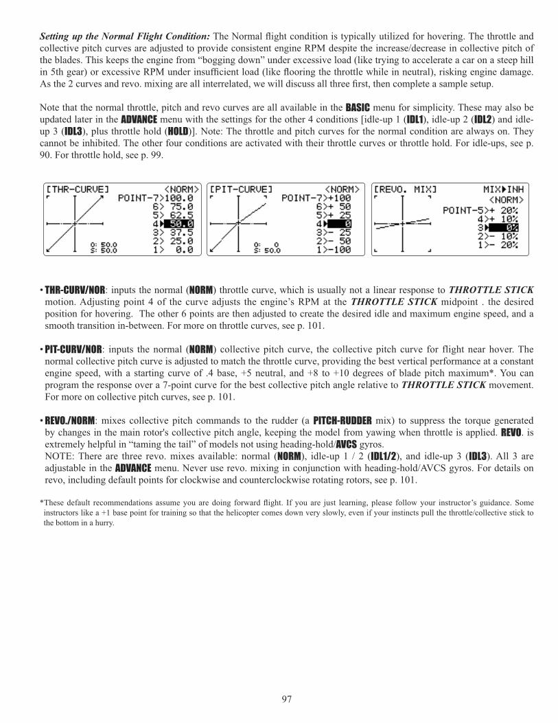
97
Setting up the Normal Flight Condition:
the blades. This keeps the engine from “bogging down” under excessive load (like trying to accelerate a car on a steep hill
Note that the normal throttle, pitch and revo curves are all available in the BASIC menu for simplicity. These may also be updated later in the ADVANCE menu with the settings for the other 4 conditions [idle-up 1 (IDL1), idle-up 2 (IDL2) and idle-up 3 (IDL3), plus throttle hold (HOLD)]. Note: The throttle and pitch curves for the normal condition are always on. They cannot be inhibited. The other four conditions are activated with their throttle curves or throttle hold. For idle-ups, see p. 90. For throttle hold, see p. 99.
• THR-CURV/NOR: inputs the normal (NORM) throttle curve, which is usually not a linear response to THROTTLE STICKmotion. Adjusting point 4 of the curve adjusts the engine’s RPM at the THROTTLE STICK midpoint . the desired position for hovering. The other 6 points are then adjusted to create the desired idle and maximum engine speed, and a smooth transition in-between. For more on throttle curves, see p. 101.
• PIT-CURV/NOR: inputs the normal (NORM) collective pitch curve, the collective pitch curve for flight near hover. The normal collective pitch curve is adjusted to match the throttle curve, providing the best vertical performance at a constant engine speed, with a starting curve of .4 base, +5 neutral, and +8 to +10 degrees of blade pitch maximum*. You can program the response over a 7-point curve for the best collective pitch angle relative to THROTTLE STICK movement. For more on collective pitch curves, see p. 101.
• REVO./NORM: mixes collective pitch commands to the rudder (a PITCH-RUDDER mix) to suppress the torque generated by changes in the main rotor's collective pitch angle, keeping the model from yawing when throttle is applied. REVO. is
AVCS gyros. NOTE: There are three revo. mixes available: normal (NORM IDL1/2), and idle-up 3 (IDL3). All 3 are adjustable in the ADVANCErevo, including default points for clockwise and counterclockwise rotating rotors, see p. 101.
the bottom in a hurry.

98
GOAL of EXAMPLE: STEPS: INPUTS:Set up Normal Flight Condit ion Throttle/Collective Pitch Curves and Revo.Base point: Adjust base point of throttle curve until engine idles reliably on ground. Adjust base point of collective pitch curve to achieve -4 degrees of blade pitch. Apply throttle until the model sits ‘light’ on its skids. Adjust base point of REVO. until model does not rotate its nose at all.
Open the THR-CURV/NOR function.5%.)
for 1 second. (If ADVANCE, again.)
C to THR-CURV/NOR.C to POINT-1. to 5%.
Open the PIT-CURV/NOR function. 8%.)
C to PIT-CURV/NOR.C to POINT-1. to 8%.
Open the REVO. /NORM function.4%.)
C to REVO. /NORM.C to MIX. to ON.C to POINT-1. to 4%.
Hover point: Adjust collective pitch curve to +5 degrees. Ease heli into a
throttle curves and rudder trim. Repeat until model hovers smoothly at half
REVO. points 2 and 3 until the model does not rotate its nose up on throttle application.
Adjust THR-CURV/NOR. Repeat above as needed.Adjust PIT-CURV/NOR. Repeat above as needed.Adjust REVO. /NORM. Repeat above as needed.
High point: Adjust collective pitch curve to +8 to +10 degrees. From hover, throttle up rapidly. If engine bogs, increase the throttle curve. If engine over-revs, increase the collective pitch curve at points 6 or 7. Apply full throttle while hovering, then descend back to hover. Adjust REVO. until the nose does not change heading.
Adjust THR-CURV/NOR. Repeat above as needed.Adjust PIT-CURV/NOR. Repeat above as needed.Adjust REVO. /NORM. Repeat above as needed.
Where next? GYRO function: see p. 107.Adjust HOV-THR and HOV-PIT if needed: see p. 104.Setting up Throttle Hold: see p. 99.Setting up idle-ups 1, 2 and 3: Throttle and collective pitch curves and revo.mixing (THR-CURVE, PIT-CURVE, REVO. MIX): see p. 101.GOVERNOR function: see p. 108.D/R,EXP: see p. 42.
THROTTLE CUT:The THROTTLE-CUT function is used to kill the engine at the end of a flight. The engine can be stopped with one touch of any switch, eliminating the need
helicopter THROTTLE-CUTlittle above idle). You must move the THROTTLE STICK back below the set point before the THROTTLE-CUT function can be reset, to avoid sudden engine acceleration. For a detailed example of throttle cut setup, see ACRO p. 41.
Note: Be sure to add the step of setting a trigger point by cursoring to THRO, then putting the THROTTLE STICK in the desired position and pressing and holding the dial for one second. Notice that this function cannot be reversed to trigger only above the stick point.

99
HELI-SPECIFIC ADVANCE MENU FUNCTIONS
THR-HOLD: This function holds the engine in the idling position and disengages it from the THROTTLE STICK when SWITCH E (10CH) or G (10CA) is moved. It is commonly used to practice auto-rotation.
Prior to setting up THR-HOLD, hook up the throttle linkage so that the carburetor is opened fully at high throttle, then use the digital trim to adjust the engine idle position. To have THR- HOLD maintain idle, move the THROTTLE STICK to the idle position, then move the hold SWITCH on and off and keep changing the offset value until the servo does not move. To lower the engine idle speed, or if you want to shut off, input a more negative number.
Adjustability:• Idling position: Range of -50% to +50% centered about the throttle idle position to get the desired engine RPM. • Switch assignment: Assigned to SWITCH G (10CA) or E (10CH) down.
Adjustable in the CONDITION SELECT (THR-HOLD item). (2-position type switch only)
• Throttle curve: Since the throttle is moved to a single preset position, no curve is available for THR-HOLD.
• Collective pitch curve: Independent curve, typically adjusted to create a blade pitch range of -4% to +10% to +12%, is automatically activated with THR-HOLD.
• Revo. mix: Since revo. mix adjusts for torque from the engine, no revo. mix is available for THR-HOLD.• Priority: The throttle hold function has priority over idle-up. Be sure that the throttle hold and idle-up SWITCHES are
in the desired positions before trying to start the engine. (We recommend starting your engine in throttle hold for safety reasons.)
• Gyro: Gyro programming includes an option to have a separate gyro setting for each condition, including THR-HOLD.This avoids the potential problem of the user being in the wrong gyro setting when going to THR-HOLD, resulting in an improper rudder offset and the model pirouetting.
GOAL of EXAMPLE: STEPS: INPUTS:Set up throttle hold.
Determine desired throttle position by idling engine, turn on THR-HOLD, and adjust percentage as required to reach the desired running point.
Open THR-HOLD function. for 1 second. (If BASIC, again.)
C to THR-HOLD.Activate the function. C to MIX. to OFF.Set desired engine position. C to POSI. to desired percent. Close.
Where next? PIT-CURVE for THR-HOLD: see p. 101.DELAY for THR-HOLD (to ease collective pitch response): see p. 103.GYRO setup: see p. 107.Setting up the Idle-Ups: Throttle and Collective pitch Curves and Revo. Mixing(TH-CURVE, PIT-CURVE, REVO. MIX) for idle-ups: see p. 101.D/R,EXP: see p. 42.

100
THR-CURVE and PIT-CURVE: These 7-point curves are utilized to best match the blade collective pitch to the engine RPM for consistent load on the engine. Curves are separately adjustable for normal, idle-up 1, idle-up 2, and idle-up 3. In addition, a separate collective pitch curve is available for throttle hold. Sample curves are displayed in the appropriate setup types (ex:
Suggested defaults: • Normal: Collective pitch curve that results in points 1, 4 and 7 providing .4, +5, (+8 to +10)* degrees pitch. A throttle
curve setting of 0, 25, 36, 50, 62.5, 75, 100%.
and the other being normal mode. The pitch curve will likely be similar to the normal curve above. • Idle-up 3: Collective pitch curve that results in points 1, 4 and 7 providing (.8 to .10), 0, (+8 to +10) degrees. A throttle
curve of 100, 75, 62.5, 50, 62.5, 75, 100 to provide full throttle for inverted maneuvers. • Throttle Hold pitch curve: Start with the normal pitch curve (for inverted autos, start from the idle-up 3 pitch curve), but
the bottom in a hurry.)
Adjustability:• Normal condition curves are editable in the BASIC menu for convenience. • All curves may be adjusted in the ADVANCE menu. • Automatically selected with the proper condition.
(including inverted). • To change which condition’s curve is being edited, cursor up to COND> and change the curve named. • For clarity, the name of the condition currently active (switched on in the radio) is shown in parentheses behind name of
condition whose curve is being edited. (Example: see curve displays below. Note that the normal condition is active but the idle-up 1 condition’s curves are currently being edited.
• Moving and deleting the curve point: The curve point (-stk-) can be moved to the left or right by turning the DIAL (up to DIAL for one second alternately.
• Copying the curve: To copy the current curve onto another condition’s curve, cursor up to COND> and press the DIAL for one second. Then select to desired condition and press the DIAL for one second.
• Idle-ups and throttle hold pitch curves may be edited even before the conditions have been made active. Activating their throttle curves activates these conditions.
REVO. MIX: This 5-point curve mix adds opposite rudder input to counteract the changes in torque when the speed and collective pitch of the blades is changed.
Adjustability:• Three separate curves available: normal for hovering; idle-ups 1 and 2 combined; and idle-3. • Normal condition curves are editable in the BASIC menu for convenience. • All curves may be adjusted in the ADVANCE menu.
that condition is activated in the programming (i.e. THROTTLE HOLD or THR-CURVE.)• To change which condition’s curve is being edited, cursor up above POINT5 and select. For clarity, the name of the
condition currently active (switched on at the radio) is shown in parentheses behind the name of the condition whose curve is being edited.

101
Revo. mixing rates are 5-point curves. For a clockwise-turning rotor, the rudder is mixed in the clockwise direction when collective pitch is increased; for counterclockwise-turning, the opposite. Change the operating direction setting by changing the signs of the numbers in the curve from plus (+) to minus (-) and vice versa. Suggested defaults:
Clockwise rotation: -20, -10, 0, +10, +20% from low throttle to high.Counterclockwise rotation: +20, +10, 0, -10, -20% from low throttle to high.Adjust to the actual values that work best for your model.
Revo. curves for idle-ups are often v-shaped to provide proper rudder input with negative pitch and increased throttle
throttle stick below half has increased throttle and negative pitch, therefore increasing torque and rotating the helicopter unless the revo. mix is also increasing appropriately.)
IDLE-UPS:different throttle curves, collective pitch curves, revo. mixing, and trims (except IDLE-3) to make the helicopter perform certain maneuvers more easily. Lastly, the gyro and dual rate functions may be set to provide separate rates per condition selected, including one for each idle-up.
to 0 pitch at half stick, positive pitch (climb upright) above half, and negative pitch (climb when inverted) below half stick. The throttle curve is adjusted to allow the engine to run consistently throughout the changes in pitch.
Additional idle-ups may be used to maximize the helicopter's flight characteristics in certain types of flight (i.e. fast forward motion, backward) or maneuvers (loops, rolls, stall turns), or even the same maneuver but changing from heading-
IDL3 does not include governor settings.)
Adjustability:• SWITCH G (10CA) or E (10CH) is programmed for normal (NORM), idle-up 1
(IDLE-UP1), and idle-up 2 (IDLE-UP2) curves. Adjustable in the CONDITION SELECT (IDLE-UP1/2, IDLE-UP3 items). (IDLE-UP1/2 3-position type switch only, IDL3 2-position type switch only)
• Activated with the throttle curve for that condition in THR-CURVE.• Curves are adjusted to maintain constant RPM even when the collective pitch
is negative (inverted). • Note that REVO.mixing has one curve for idle-ups 1 and 2 and a second curve just for idle-up3. • Gyro settings may be set separately for each idle-up. (See p. 101.)
conditions like gyro. (See p. 101.) • Activating OFFSET makes the TRIM LEVERS adjust the trim separately in each of the idle-up conditions.
For an example of throttle and pitch curves and revo, please see Normal Flight Condition Setup, p. 97.

102
OFFSET: Optional separate trims in addition to those for the normal condition. This function is used to automatically change
helicopter tends to drift to the right at high speed, so an aileron offset may be applied to offset the helicopter to the left. The necessary elevator offset varies with model geometry, so it must be determined by noting collective pitch changes at high speed. The rudder offset is affected by both revo. mixing and trim lever movement while in the offset function.
Adjustability:• Complete switch assignability, plus a CONDITION SELECT
switches between individual trims for each of the idle-ups. • When OFFSET is active (its switch is on), moving the TRIM LEVERS adjust
the stored offset, not the trims in the normal condition. • When OFFSET is inactive (its switch is off), the OFFSET and any trim adjustments
condition.)• When OFFSET
• Rapid jumps caused by large offsets can be slowed using the DELAY function.
*During OFFSET operation, the aileron, elevator, and rudder travels are displayed on each trim display in the Startup screen.
NOTE:
GOAL of EXAMPLE: STEPS: INPUTS:Set up separate trims for each of the three idle-up conditions.
Adjust the idle-up 2 rudder trim to correct for torque at high speeds.
Open the OFFSET function. for 1 second. (If BASIC, again.)
C to OFFSET.Activate the function. C to MIX. to OFF or ON.Change switch setting to Cond.(No need to change SW.)
already Cond.
Select IDL2. C to No. to IDL2.Adjust trim settings as needed. (Ex:rudder to +8%.)
C to RUDD. to +8%.
trims between normal and idle-up 2. E (T10CH) or G (T10CA) from NORMAL to IDL2. Check that rudder trim changes.
Where next? DELAY: see p. 103.THR-HOLD: see p. 99.Setting up the Idle-Ups: Throttle and Collective pitch Curves and Revo. Mixing (THR-CURVE, PIT-CURVE, REVO. MIX) for idle-ups: see p. 101.

103
DELAY: The Delay function provides a smooth transition between the trim positions whenever OFFSET, REVO. MIXING, or THROTTLE HOLD functions are turned on and off.
Adjustability:• Separate delay times are available for aileron, elevator, rudder, throttle, and
pitch.• With a 50% delay setting, the servo takes about a half-second to move to its
new position...quite a long time.
GOAL of EXAMPLE: STEPS: INPUTS:Set up a delay on all channels to ease
to another so there are no "hard jumps."
Open the DELAY function. for 1 second. (If BASIC, again.)
C to DELAY.Adjust AILE response as needed. (Ex: aileron to +8%.)
to +8%.
Repeat for other channels. C to ELEV. Repeat step above. Close menus and confirm slowed transitions. E (T10CH) or G (T10CA) from
NORMAL to IDL2. Check that servos move gradually to new positions.
Where next? THR-HOLD: see p. 99.Setting up the Idle-Ups: Throttle and Collective pitch Curves and Revo. Mixing (THR-CURVE, PIT-CURVE, REVO. MIX) for idle-ups: see p. 101.

104
HOVERING ADJUSTMENTS (HOV-THR and HOV-PIT):
curves for ideal setup.
Adjustability:
• Both adjustments may be inhibited if not desired. • Both adjustments may also be set to NULL, temporarily turning off the knob but maintaining the last memorized setting. • Adjustments may be memorized and then the knobs returned to center point to use that amount of adjustment. Allows
easy use of the trimming knobs for multiple models. (Note that when memorization is repeated with the knob offset from center, the trim value accumulates.)
• Adjustments are quickly reset to the initial value by turning the dial until the trim reads 0%, memorizing, then returning the knob to its center position.
• Note that all functions, including these, assume the model hovers at half stick. • Available in normal (NORM NORM/IDL1) condition only.
GOAL of EXAMPLE: STEPS: INPUTS:Fine-tune hovering with the hovering adjustments. Remember these affect only the hovering (normal) condition.
Adjust throttle and collective pitch curves until model hovers nicely. In
curves near hover point independently with HOV-THR and HOV-PIT knobs.
Open the HOV-THR function. for 1 second. (If BASIC, again.)
C to HOV-THR.Optional: change which knob adjust seach hovering curve. NULL locks in curve in last stored position.
C to VR.
to desired knob and direction.
Store the current dial settings prior to selecting another model.
C to RATE.
for one second to store.
or VR(C) to center.Close.
Open the HOV-PIT function. C to HOV-PIT.Store the current dial settings prior to selecting another model.
C to RATE.
for one second to store.
or VR(A) to center.Close.
Where next? THR-HOLD: see p. 99.Setting up the Idle-Ups: Throttle and Collective pitch Curves and Revo. Mixing (TH-CURVE, PIT-CURVE, REVO. MIX) for idle-ups: see p. 101.D/R,EXP: see p. 42.

105
HIGH/LOW PITCH (HI/LO-PIT):
idle-up 2, idle-up 3, throttle hold).
Adjustability:
• The conditions are activated in the CONDITION SELECT function (p.100). • Both adjustments may be set to MANUAL, temporarily turning off the knob. • Adjustments may be memorized and then return the knobs to center point to
use that amount of adjustment. Allows easy use of the trimming knobs for multiple models.
GOAL of EXAMPLE: STEPS: INPUTS:Set up a high pitch curve in the idle-up 1 condition.
Open the HI/LO-PIT function. for 1 second. (If BASIC, again.)
C to HI/LO-PIT.Select the idle-up 1 condition. C to NORM. to IDL1.Set the rate. (Ex: 80%) C to HI-PIT.
to 80%.Optional: change which knob adjusts high pitch curve.
C to VR.
to desired knob and direction. Store the current dial settings prior to selecting another model.
C to HI-PIT.
for one second to store.
or VR(E) to center.Close.
Where next? PIT-CURVE: see p. 100.HOV-PIT: see p. 104.

106
What is a gyro? A gyroscope is an electronic unit that senses motion and corrects for it. For example, if the wind blows
How does it help in helicopter setup? A good gyro will totally eliminate the need for revo. mixing. The gyro will sense and correct the unwanted motion for you, so you don’t have to spend time to get a complex curve operating properly.
Gyro sensor kinds: There are many different kinds of gyros. Early gyros were mechanical, with a spinning drum similar to a child’s gyroscope toy. The next generation utilized a special type of crystal, called piezoelectric, which sensed the motion
machines, or computer chips, sense the motion. SMM is far more accurate and less susceptible to inaccuracies caused by temperature changes, etc.
Types of gyro responses: • Normal: sense motion and dampen it (if the gyro rotates off course for 2 seconds, it corrects for 2 seconds).
until the same rotation is achieved. • Stick priority: a feature on most high-end gyros. The more input given on the channel the gyro controls, the less sensitive
the gain is automatically. This way, if you give a large input for a stall turn, for example, the gyro turns itself off and
model straight. (If your gyro does not include stick priority, you can manually create it. Please see www.futaba-rc.com\faq\.)
Choosing the right gyro for your skills, your helicopter, and your budget: • Mechanical: some are still available. They are very challenging to set up and not as reliable as piezo or SMM. • Non-Heading-Hold Piezo: these are now inexpensive gyros that are reliable and easy to set up. Some have dual rates and
• Heading-Hold Piezo: Until recently, the cream of the crop. Expensive, and more complex to set up. Adds GPS-like
• Heading-Hold SMM: 21st Century gyro technology. Computer chip technology. Expensive, easier set up, higher
using specialized digital servos. Examples:
• GY401: Simpler set up. Ideal for learning aerobatics through 3D. • GY502: Better centering than 401 for more advanced aerobatics. Ideal through Class III competition. • GY611: Exceptional center. Extremely fast response time. Requires specialized servo.
GYROgain, the more correction the gyro provides and the “softer” or less responsive the helicopter feels.) This function makes
Adjustability:• Plug the gyro’s sensitivity adjustment to channel 5 of the receiver. (not assignable) • STD GY• Full switch assignability or may select Cond. option. • Cond. option provides separate gyro settings, one for each condition, automatically selected with the condition. Allows
• Each gyro setting may be set from 0 to +100 (NOR100% to AVC100%) gain, equating to ATV settings of -100% to +100%.
Negative settings trigger normal mode; positive settings are AVCS mode. • Larger percentages indicate more gain, or gyro responsiveness. • Tail wagging or shaking indicates excessive gain settings. Turn down gyro setting until wag stops.

107
Gain Example for AVCS/Heading-hold Gyros (GY)
GOAL of EXAMPLE: STEPS: INPUTS:
1 and 2 and normal mode setting in idle-up3 and normal.
Open and activate the GYRO SENSEfunction.
for 1 second. (If BASIC, again.)
C to GYRO SENSE.Activate the function. C to MIX. to ACT.Optional: change gyro type to Heading-hold (GY).
C to MODE. to GY.
Optional: change switch assignment. Ex: select Cond.
C to SW. to Cond.
Adjust gyro rates as needed. (Ex: NORM, IDL3 to NOR 50%. IDL1 and 2to AVC 50% as starting points.)
C to NORM. to NOR 50%.C to IDL1. to AVC 50%.
Repeat.Close the function.
Where next? GOVERNOR: see p. 108.D/R,EXP: see p. 42.DELAY: see p. 103.
50%0% +100%
"Heading Hold Mode""Normal Mode"
CVA%001%0RON%001
GY
STD

108
GOVERNORS:
What is a governor? A governor is made up of a set of sensors which read the RPM of the helicopter’s head, and a control unit that automatically adjusts the throttle setting to maintain a constant head speed regardless of changes in pitch of blades, weather conditions, etc. Governors are extremely popular in competition helicopters due to the consistency provided.
How does it help in helicopter setup? The governor eliminates the need to spend large amounts of time setting up throttle curves, as it automatically adjusts the engine’s RPM to maintain the desired head speed.
GOVERNOR: The Governor mixing function is used to adjust the GV-1 (Governor) speed settings (rS1, rS2, rS3) from the transmitter. (If you are using a different governor, follow the manufacturer's instructions.)
Adjustability:
ch8 and changing CUT-CH setting.
not to assign governor off to a condition switch if you want the governor to function in that condition.
CH8 can be used for other functions.
be created using an additional channel and a programmable mix. See www.futaba-rc.com\faq\ for details.
GV-1 connectionsMagnetic sensor
Throttle servo
Control amp
Mixture servoConnected only whenfuel mixture functionused.
Throttlechannel
Speed setting channelConnected when speed set fromtransmitter
Governor ON/OFF / Mixture trim channelConnected when the governor is turned on and offfrom transmitter and when mixture trim function isused, or when mixture curve data is sent from transmit-ter to governor
Receiver

109
The GV-1 controls throttle when it is active, so the throttle will not obey any FailSafe settings preset for throttle in the
and the throttle obeys the FailSafe throttle commands.
Expert Tip: Mounting the GV-1 to the counter gear instead of the fan
Setting example:
Governor Speed Switch Position(Switch C or Cond.) Rate (%) Adjustment from Tx.
RS1: OFF UP or NORM 0Use up to 0%.
(Governor speed display reads “off”.)RS2: 1400 CNTR or IDL1 50 Speed adjusted by raising and lowering rate.RS3: 1700 DOWN or IDL2 100 Speed adjusted by lowering rate.
*The relationship of the governor speed setting rS1~rS3 and the switch positions conforms to the table above. *In throttle hold, always check that the governor is off. *If the speed value rises when the cut switch is activated, reverse the “DIR” setting from UP to DOWN or vice versa.
GOAL of EXAMPLE: STEPS: INPUTS:S e t u p a G V 1 g o v e r n o r t o u s e bo th channe l s i n to t he r ece ive r and switch between the governor settings automatically when changing conditions. Consider setting the battery Fail Safe settings and other helpful functions on the GV-1 itself.
Open and act ivate the G O V E R N O Rfunction.
for 1 second. (If BASIC, again.)
C to GOVERNOR.Activate the function. C to MIX. to ACT.Optional: change cut-off channel to channel 8 and assign switch and direction for on/off (channel 8).
C to cut-CH to +CH8.C t o c u t - S W . t o d e s i r e d
SWITCH.Optional: change switch assignment to select governor settings. Ex: select switch that selects the conditions.
C to SW.
to Cond.
Adjust governor speed settings per switch position or condition as needed.(Ex: defaults are fine.) Allows head speed adjustment from transmitter.
C to each Cond position.
or as needed.C to next Cond position. Repeat.
Close the function.
Where next? GYRO: see p. 107.Adjust FailSafe (F/S) settings (p. 50).
See p. 101.D/R,EXP and END
POINT SWASH AFR: p. 42, 39, 95.

110
GLOSSARY
rolls. Helicopters: combining 2 or more maneuvers, such as rolling loop.
4.8V: 4.8 volt battery pack, made of 4 Ni-Cd 1.2V cells. See Accessories.
5-cell: 6.0 volt battery pack, made of 4 alkaline cells or 5 Ni-Cd cells. See Accessories.
6V (6Volt): battery pack, made of 4 alkaline cells or 5 Ni-Cd cells. See Accessories.
ACCELERATION: a delay mix which richens engine mixture and then returns to normal to compensate for abrupt throttle changes. See THROTTLE-NEEDLE. ............................................................................................................................................ 65
Accessories: additional optional items which may be used with your 10C. ........................................................................ 10
ACRO: model type designed for use with powered aircraft. Selected in the MODEL submenu under TYPE. ........................... 34
ACRO vs GLID comparison. .................................................................................................................................................... 34
ACT. Active. Make a feature able to be utilized. Opposite of INH. Only visible in certain features.
Adjustable Function Rate: see SWASH AFR.
END POINT.
Adjustable Travel Limited (ATL): End point adjustment for low end only, for throttle channel. See ATL.
END POINT.
ADVANCEadvanced features.
AFR: Adjustable function rate. Used only in HELI model types with CCPM heads. See SWASH AFR.
AILE-2: second aileron servo assignment. See Twin aileron servos.
AILE1/2/3/4: Designation for the individual servos that are being commanded by the aileron command. Ex: when using ailevators, the two elevator servos are also acting as ailerons 3 and 4 (unless you set their values to 0). See Twin aileron servos and Twin elevator servos.
AILE/RUDD (GLID): You can select a pre-programed mix which is used to mix the rudders with aileron operation or the
especially in knife-edge. ...................................................................................................................................................... 81
Aileron: surface that controls the roll of the model. Also called cyclic roll on a helicopter.
Programmable mix. This is the default setup of one mix in GLID.
Aileron-to-rudder mix: Mixing that automatically creates a “coordinated turn”. Not a preprogrammed mix. See Programmable mix. This is the default setup of one curve mix in HELI GLID.
Aileron Differential: Decreased down aileron travel when compared to up aileron travel. Minimizes “dragging” the low wing and creates more axial rolls. See Twin aileron servos. .............................................................................................. 51
Ailevator: two elevators on separate channels, also capable of acting as additional ailerons. See Twin elevator servos.
AILEVATORS: (ACRO) Twin elevator servos plugged into separate channels, used to control elevator with the option to also act as ailerons in conjunction with the primary ailerons. ..................................................................................................... 56
Airbrake-to-elevator mixing: (GLID) Applies up or down elevator when airbrakes are deployed, correcting for any pitch change from the added drag. Not a preprogrammed mix. See Programmable mix.
Airbrake: (GLID CHANNEL 3 (NORMALLY THROTTLE) STICK.
AIRBRAKE: (ACRO

111
triggered by THROTTLE STICK POSITION. For similar glider programming, see BUTTERFLY. ...................................... 63
...................... 5
AST: Adjustable Servo Travel. See END POINT.
ATL: Adjustable Travel Limited. Standard type of trim used for throttle, where the trim is effective only in the idle portion of the THROTTLE STICK POSITION. Normal trims affect the entire travel of the servo (ex: elevator trims), but ATLtrims only the low end of the throttle movement, allowing throttle idle adjustments that donit over-drive the servo at full throttle. ................................................................................................................................................................................. 38
ATV: Older, less clear terminology for end point adjustment. See END POINT.
Autorotation: The ability of a helicopter to land safely without engine power, using the stored energy in the bladeis rotation
AUX-CH: Auxiliary channel setup. Used to assign which KNOBS SWITCHES SLIDERS control channels 5-9. Includes CH9 servo reverse. Also allows assignment of a channel to mixing only (assigned as NULL), with no primary control. .... 46
Backup battery: battery used to protect data storage in case of removal of master transmitter battery. In most Futaba radios, including the 10C, EEPROM data storage is used, so no backup battery is used or needed.
BACKUP ERROR: transmitter's hard-coded memory has been lost. Send for service immediately. ....................................... 24
Base-Loaded antenna: also called Whip antenna. Aftermarket equipment not approved by Futaba.
Basic model setups: guidelines to setting up the most basic models of each type. ........................ ACRO 27 GLID 76 HELI 90
BASIC .............. ACRO 30 GLID 78 HELI 93
Battery care and charging. (Charging the Ni-Cd batteries) ................................................................................................. 15
Battery FailSafe: determines how the receiver indicates an airborne pack low-battery warning. Defaults: 56% throttle, requires throttle to idle to override. To adjust the warning point, set a THROTTLE STICK POSITION in F/S. .............. 50
BEEP: tone emitted by transmitter to signify a variety of situations. See Error messages.
Binding: friction in a joint exceeding the movement of the linkage. Sticking or inability to continue movement. The servo
struggle.
GLIDreaction to lowering the brake flap, 2) increase brake flap area by including the flaperons, and 3) add lift to increase maneuverability. Not a preprogrammed mix. See Programmable mix.
Buddy Box: see Trainer box.
BUTTERFLY: (GLID) [also called crow, AIRBRAKE(ACROwithout spoilers or airbrakes. Note: More adjustable programming is available in ACRO, AIRBRAKE. ................................ 63
CAMBER FLAP (GLID........................................... 86
CAMBER MIX (GLID
changes caused by camber operation can be corrected. ....................................................................................................... 85
CAMPac .................................................... 10
CCPM: Cyclic (pitch and roll) Collective Pitch Mixing. Multiple servos work in unison on the helicopteris head to create one or more of the control functions. Ex: 3 servos set at 120 degrees operate the entire head. The 2 forward servos work together to rotate both the blade's pitch and the roll cyclic (aileron) in a HR3 head type. See MODEL TYPE, HELI.
CH5&6: setting in AILE-2 that allows the second aileron servo to be in channel 5. See Twin aileron servos.
CH6 or 7: default setting in AILE-2. Second aileron servo is in channel 6 or 7 depending on function used. See Twin aileron

112
servos.
AUX-CH. ...................................................................................... 46
Channel delay: see THROTTLE DELAY (ACRO) and DELAY(HELI).
Charge: to increase the electrical energy, measured as voltage, available in a battery pack. See Battery care and charging.
Condition: (HELI IDLEUP 1, 2, 3 and THROTTLE HOLD.
Contact information, North American Service Center. .......................................................................................................... 3
Copy model: see MODEL COPY.
Crow: see BUTTERFLY (GLID) and AIRBRAKE (ACRO).
Cursor: See SELECT BUTTONS.
Curve Mix: a mix that does not have the same reaction at all points along the master channel. See Programmable mix.
Cyclic: horizontal controls on a helicopter. Cyclic pitch is typically called elevator. Cyclic roll is typically called aileron.
RESET.
DELAY: (HELI) slows the servo’s reaction time when changing from one condition to another. Eases any “jumps” in transition from one pitch setting to another, etc. Also see THROTTLE DELAY, p. 59 (ACRO). ................................................................ 103
Delta peak charger: common name for a specialized charger designed and required to properly peak charge both NiMH and NiCd batteries, actually called a Zero Delta V Peak Charger. See Battery Care and Charging.
Dial: transmitter’s rotary control and button used in various ways during programming. .................................................. 11
Dial mix: mix that uses a knob or slider as the master control, moving the slave servo based upon the movement of the knob or slider. See Prog. mix.
Differential: uneven movement in each direction of a control surface. Usually used when discussing ailerons or when describing an undesirable unevenness in movement of other controls. See Twin aileron servos.
reversed polarity during charging. ....................................................................................................................................... 15
DIR-SW: switches that change between the 4 separate directions of snaps available. See SNAP ROLL.
Discharge: to deplete the electrical energy in a battery pack, usually to its lowest safe voltage, for storage or as a part of regular maintenance. See Battery care and charging.
DP16K: see CAMPac.
DSC: direct servo control. Programming and cable combination which allows operation of all receiver channels and functions without the transmitter transmitting. Plugs into trainer port of transmitter and special plug on receiver. Leave power off for both transmitter and receiver.
Dual aileron servos: (ACRO GLIDaction or aileron differential. See Twin aileron servos. ....................................................................................................... 51
Dual elevator servos: (ACRO GLID) a model using 2 servos on 2 separate channels to operate elevators. Includes elevon, V-tail, ailevator. See Twin elevator servos. ......................................................................................................................... 56
Dual rates (D/R,EXP
Includes exponential function, see EXP. ................................................................................................................................ 42
Elapsed Time Counter reset: see TIMER. ............................................................................................................................... 45
ELE1/2/3/4: designation for the individual servos that are being commanded by the elevator command. Ex: when using elevon, the two wing servos are acting as elevators 1 and 2. See Twin elevator servos.

113
Elevator: surface which controls the model’s rate of climb or descent. Also called cyclic pitch on helicopters.
Elevator-to-airbrake mix: (GLID) used to allow the model to loop even tighter on elevator input by having airbrakes work with elevators. Not a preprogrammed mix. See Programmable mix. This is the default programming for one curve mix in GLID.
ACRO GLIDslower speeds, make tighter loops or turns, etc. Not a preprogrammed mix. See Programmable mix. This is the default setting of one mix in ACRO and GLID.
Elevator-to-pitch mix: (HELI) used to adjust pitch to counter the loss of angle of attack when elevator input is given. Not a preprogrammed mix. See Programmable mix. This is the default setting of one mix in HELI.
ELEVONelevator servos. .................................................................................................................................................................... 56
Elevons: two surfaces, one on each wing, which work as both ailerons and elevators. See ELEVON.
END BUTTON: control button used during programming to return to previous menu or close menu altogether.
END POINT: often abbreviated EPA. Adjusts the total travel in each direction of proportional servos regardless of their control assignment. Ex: adjustment to AIL channel will adjust only the servo plugged into channel 1 even if being used
setting. .................................................................................................................................................................................. 39
Engine cut: see THROTTLE-CUT.
EPA: see END POINT.
........................................ 24
Exponential (D/R,EXP): adjustment to the relationship of STICK MOVEMENT to servo movement, typically used to soften
overly sensitive models around center. ................................................................................................................................ 42
FASST: Futaba Advanced Spread Spectrum Technology
FailSafe (F/S): sets servo positions when interference is encountered or signal is lost. Available only in PCM transmission mode. Also includes Battery FailSafe settings. .................................................................................................................... 50
FLAP1/2/3/4
Twin aileron servos and Twin elevator servos.
Flap-to-aileron mix: (ACRO GLID) used to create full span flap reaction in flight. Not a preprogrammed mix. See Programmable mix. This is the default setup of one mix in GLID.
Flap-to-elevator mix: (ACRO GLID
preprogrammed mix. See Programmable mix. This is the default setup of one mix in ACRO and GLID.
FLAPERON Twin aileron servos. ...................................................................................................................................................................... 51
FLAP-TRIM KNOB. May also be used as Twin aileron servos. .................. 53
Frequency: channel on which radio transmits. .................................................................................................................... 22
Frequency band: In the entire spectrum, transmissions are designated in terms of “frequency bands” which exhibit similar
control aircraft. 50MHz band is available for model use by those holding a HAM amateur radio operator’s license. 75MHz is solely for remote control ground models. 27MHz is legal for air or ground use. To change bands on the 9C, simply purchase and install a module on the proper band. Receiver band MUST be changed by a service center. ....................... 22
Fuel mixture control: (ACRO HELI) see THROTTLE-NEEDLE.

114
FUNC: function mode of TRAINER, allows student radio to use the computer programming for that channel in the master
TRAINER.
Gain: the responsiveness or amount of control given the gyro. On a high gain, the gyro is very active and overrides nearly all other actions. Too high a gain may result in “wagging” at the surface as the gyro over-corrects repeatedly in each direction. See GYRO SENS.
Gear doors: covers for retractable landing gear, may be operated separately from landing gear on some models. ............ 74
GLID: model type, glider. ...................................................................................................................................................... 75
Governor: electronic device that reads the speed at which the head is spinning, and adjusts the throttle servo to maintain the desired speed.
GOVERNOR: (HELI) programming which eases the setup of the GV-1 governor. ................................................................. 106
Gyros and Governors and GOVERNOR for details.
Gyro, gyroscope: equipment that senses change in direction and provides input to compensate for that change. For description of aircraft use, see p. 66. For description of types, and helicopter use, see GYRO SENS.
GYRO SENS (ACRO HELI): gyro sensitivity programming designed to ease the setup and use of gyroscopes on model airplanes and helicopters. Manual pages include extensive descriptions of gyro types. ............................................. 73, 106
Gyros and Governors ......................................................................................................................................................... 106
angle has been returned. See Gyros and Governors.
HELI: model type, rotary wing. See MODEL TYPE.
least support a 5-channel helicopter. The 9CA super and 9CH super radios both contain all needed programming. The 9CH super has a more heli-friendly layout (through switch positioning and no ratchet on throttle for easier hovering)
HI/LO-PIT (HELI ............................................................. 105
High band: 72MHz equipment on a channel from 36 to 60. Receiver channel may be changed to any channel within the ............................... 8
High Rate: See D/R,EXP.
Hover: to maintain a stationary position relative to a point on the ground.
HOVERING PITCH: see Hovering setups.
HOVERING THROTTLE: see Hovering setups.
THROTTLE STICK position (the ideal hovering point). .................................................................................................................................................................. 104
Idle management: varying settings and control of the modelis idle. Ex: using IDLE-DOWN to lower engine's idle point for landings and certain maneuvers; using THR-CUT function to safely and accurately shut the engine off as needed without requiring constant adjustment of throttle trims. ................................................................................................................... 40
IDLE-DOWN:: offset mix that slows the engineis idle point (decreasing the amount of travel of the throttle servo when at low THROTTLE STICK POSITION). Typically used to keep the model sitting still on the runway prior to take off, for slow aerobatic maneuvers such as spins, and for landings. See Idle management. ..................................................................... 40
IDLE-UPnormal condition. Note: the idle-ups are activated by activating their throttle curves. Also note that OFFSET is available to create separate trims within each condition. ...................................................................................................................... 101
115
THROTTLE-NEEDLE.
INH
Inhibit: see INH.
Installation: radio installation and setup. ............................................................................................................................. 18
instead learning to recognize the modelis behaviors when inverted and compensate appropriately.
Kill switch: (1) throttle cut switch to close carburetor (see THR-CUT, p. 40). (2) gasoline ignition engine kill switch which removes spark to the plugs to stop the engine. .................................................................................................................... 74
Launch setting: (GLID) see START-OFS.
Linear Mix: a mix that maintains the same relationship of master to slave throughout the whole range. Ex: a mix from
points of travel. See Programmable mix.
LINK: mixing function that allows multiple mixes to work in conjunction. See Programmable mix.
Lithium battery: see Backup battery.
Linear: linear, directly proportional. See AIRBRAKE.
Low Band: 72MHz equipment on a channel from 11 to 35. Receiver channel may be changed to any channel within the low band without needing retuning. ....................................................................................................................................... 8
LOGIC SW: can be assigned to the following functions: THR-CUT, IDLE DOWN, AUX-CH, TIMER, PROG. MIX, AIRBRAKE, ELEV-FLAP, and AILE-FLAP functions. The logic switch can activate functions by two switches combination. The 2 types of logic, either AND or OR, can be selected. ..................................................................................................................................... 38
LOW BATTERY Error messages.
Low rate: see D/R, EXP.
MANUAL: controlled by a switch. Ex: see AIRBRAKE.
Master: the primary control. See Programmable mix.
Mechanical gyro: uses a mechanical gyroscope (like a child’s toy gyro) to sense change of angle. See Gyros and Governors.
MEMORY MODULE INITIALIZE: warning to indicate that the CAMPac installed in the port is not yet formatted or formatted for a different model of transmitter. Pressing the Dial initializes the CAMPac, deleting any existing data and formatting the CAMPac for use in the 10C. See Error codes.
MHz: Megahertz. Unit used to express frequency. 72MHz channels are aircraft only frequencies; 75MHz are ground model only frequencies; 27MHz are air and ground both. 50MHz is legal for HAM amateur license holders. See Frequency.
Mix, mixing rate, mix offset, mix links: See Programmable mix.
MIXER ALERT Errormessages.
STICK movements. All 10C radios shipped in the US are Mode 2,with elevator and aileron on the right STICK. To change mode, please visit www.futaba-rc.com.
MODE BUTTON: control button on radio’s face used in various parts of programming. ................................................. 11
MODEL COPY: used to duplicate the settings of one model already in memory into a second model memory. Often used to

116
from the CAMpac data storage unit. ................................................................................................................................... 31
MODEL NAME: gives each model memory an 8-character name for easy recognition. In MODEL submenu. .......................... 32
MODEL RESET: restore all data in a single model memory to defaults, including name and model type. See RESET.
MODEL SELECT MODEL submenu. ................................................ 30
MODEL SELECTION ERROR: the memory last loaded in the transmitter is not currently available (usually because it is on a CAMPac not currently in the transmitter). See Error messages.
MODEL TYPE: select the type of model the aircraft is, including airplane, 2 glider types, and 5 heli types. ......................... 34
MODUL: modulation, means of transmitting data (PPM, PCM). In PARAMETER submenu. ..................................................... 35
components. Transmission frequency can be safely, legally and easily changed (including from band to band) by changing the module. TP-FM is the standard module, available on any 50MHz or 72MHz frequency. You may also purchase TP75FM for ground use, 75MHz. .......................................................................................................................................... 9
MOTOR CUT (GLIDposition. ................................................................................................................................................................................ 79
Name: see MODEL NAME.
Neckstrap: optional strap to suspend transmitter during use. Futaba stock # FTA8. See Accessories.
Ni-Cd: Nickel Cadmium rechargeable battery. Typically used to power transmitter and receiver. See Battery care and charging.
NiMH: Nickel Metal Hydride rechargeable battery. Newer battery technology than Ni-Cd. Longer run times but more
NORMAL: trainer mode that does not give student radio the computer programming features of the master radio. See Trainer.
NT8S: standard transmitter battery pack. See Accessories.
NULL: not assigned or never changed. Ex: a mix which has a null switch assignment is always active, and can never be
OFFSET: (HELI) separate trim settings available to each idle-up (using CONDITION) setting, or assigned to separate switches from the condition switches. When offset is ON, movement of the trim levers adjusts the OFFSET, not the normal condition's trims. .................................................................................................................................................................................. 102
OFFSETs ......................................................................... 84
Offset mix: mix that independently moves the slave servo a set percentage of its total throw, not in relation to any master. See Programmable mix.
PA2: Pilot Assist. Optional onboard device that uses optical sensors to correct modelis orientation to upright.
PARAMETER ATL. ... 33
PCM: Pulse Code Modulation. An electronically encoded method of transmitting data to a receiver to help minimize the effects of interference. (Transmission is on an FM wavelength, and uses FM crystals, module and trainer cord.). See Modulation.
Peak Charger: charger that automatically stops charging when the battery is fully charged (commonly called ipeakedi). See Battery care and charging.
Piezo gyro: gyro that uses a piezo crystal to sense angular changes. See Gyros and Governors.
Pitch-to-rudder mix: see REVO.

117
PITCH CURVE: (HELISTICKAdjusted to provide ideal blade response for various types of maneuvers being performed. For simplicity, the normal condition's curve may be set in the BASIC menu. All 5 curves are also adjustable in the ADVANCE menu. ......................... 99
PPM: Pulse Position Modulation. Also known as FM. Type of signal transmission. See Modulation.
Programmable mix: used to cause specific servo responses to specific inputs separate from the basic control setups. ........................................................................................................ 68
............................................................................................................................................ 18
Rate: amount of control given. Ex: see Programmable mix.
RESET: to delete all data in the existing model only. User CANNOT erase all data in the radio. Only service center can do so. Part of PARAMETER submenu. ......................................................................................................................................... 33
..................................................... 74
REVERSE: servo reversing. Used to reverse the direction of a servo to ease installation and set up. .................................... 38
Rudder-to-aileron mix: (ACRO GLID) used to counteract undesirable roll (roll coupling) that happens with rudder input, especially in knife-edge. Gives proper aileron input to counteract roll coupling when rudder is applied. Not a preprogrammed mix. See Programmable mix. This is the default programming for one linear and one curve mix in ACROand GLID.
Rudder-to-elevator mix: used to counteract undesirable pitch (pitch coupling) with rudder input, especially in knife edge Programmable mix. This is the default programming for one curve mix in ACRO.
Rudder-to-throttle mix: (HELI) adds throttle to counter the added load from increasing pitch of the tail blades, maintaining a constant head-speed with rudder. (This is a minor effect and is not critical in most helicopters.) Not a preprogrammed mix. See Programmable mix.
Rx: receiver.
SAFE MODE: feature in snap roll programming that does not allow a snap roll if landing gear is lowered. See Snap roll.
Sailplane: glider, non-powered model aircraft type. See GLID MODEL TYPE.
Select a model: see MODEL SELECT.
Service Center. ....................................................................................................................................................................... 3
SERVOuser movements. Also includes a servo test feature. ............................................................................................................ 49
Servo reversing: see REVERSE.
Servo Slow: see Channel delay.
Servo testing, servo display: See SERVO.
SET: to accept. Usually done by pressing and holding the dial when instructed.
Slave: channel that moves in response to the command of the master. See Programmable mix.
Slaving servos: see programmable mix. ............................................................................................................................. 68
Slider assignability: sliders on side of radio, known as VR(D) and VR(E) in programming, may be assigned to control channels 5-8 in AUX-CH, used as the primary control of a mix in programmable mixes, etc.
Slow: see Channel delay.
Smoke system: injects a specialized smoke oil into the hot exhaust to create air-show like smoke trails. ......................... 74
SNAP ROLL: (ACRO

118
switch. 10C of fers 4 separate snaps with 1 or 2 switches used for selection. ..................................................................... 59
SPOILER MIX (GLID SPOILERMIX works linking with BUTTERFLY function. ....................................................................................................................... 83
START DELAY (GLID 1A+1F only): automatically switch the offset trims (OFFSET) from the START condition's trims to the normal cndition's trims after proceeding the delay time (max.10sec.) which is preset when activating the START condition. It is convenient for hand launch glider. ................................................................................................................................ 85
Stick adjustments: change stick tension and height. ............................................................................................................ 16
STk-THR: assigned to THROTTLE STICK. See AIRBRAKE for example.
SUB-TRIM
.................................................................................................................................................................... 49
SWASH AFR: (HELI, CCPM types only) adjustment of the travel of all servos involved in the particular controlis movement only during the movement of that control. Ex: reverse the direction of movement of collective pitch while not affecting the direction of movement of either cyclic control. ................................................................................................................... 95
Swashplate type: (HELIfour available types of "CCPM." ......................................................................................................................................... 95
SWASH-THR (HELI): is corrected the tendency of the model to change altitude when the rotor is tilted by aileron, elevator, and other controls. ................................................................................................................................................................ 85
Switch programmability: MOST features are reassignable to a variety of switches, including simply moving an auxiliary AUX-CH.
10C at the time of this printing. ........................................................................................................................................... 10
........................................................................................................................................................ 9
Not a preprogrammed mix. See Programmable mix.
THR-DELAY: (ACRO) throttle delay, slows engine servo response to imitate the spool-up action of a turbine engine. May also be used creatively to create a delayed servo on a different function (see www.futaba-rc.com\faq\faq-9c.html.) ............... 66
THR-REV: reverses the throttle trim function to the top of the THROTTLE STICK. ........................................................... 38
THROTTLE-NEEDLE: (ACRO HELI) curve mix that adjusts a second servo, controlling the engine’s mixture, to get optimum RPM and performance from the engine at all settings. ........................................................................................................ 65
Throttle-to-rudder mix: used to compensate with rudder when throttle is applied on take off. Not a preprogrammed mix. See Programmable mix. This is the default setting of a mix in ACRO and GLID.
THROTTLE CURVE: (HELI) adjusts how the servo responds to the THROTTLE STICK position along a 5 point curve. Separate curves available for each idle-up and normal. For simplicity, normal curve may be edited from BASIC menu. All curves may be edited together in the ADVANCE menu. Activating an idle-up’s throttle curve is what activates that idle-up. .86,89
Throttle cut or throttle kill: THR-CUT. (ACRO HELI) Offset mix which closes the throttle servo to a set position when the ............................................. 40
THROTTLE HOLD: (HELI) makes the throttle servo non-responsive to THROTTLE STICK position, and moves the throttle to idle. Used to practice autorotations. NOTE: THR-HOLD must be activated, then the default pitch curve adjusted properly. ............................................................................................................................................................................................. 99
THROTTLE MIX (HELIaltitude when the rotor is tilted by aileron, elevator, and rudder controls. .......................................................................... 96

119
Throttle trim adjustment: see ATL to change throttle trim from “idle only” to full trim control like all other channels. See THR-REV to reverse THROTTLE STICK completely, including moving trim to the top of the THROTTLE STICK. See also Idle management for details on idle down and throttle cut functions.
TIMERmay be programmed. ........................................................................................................................................................... 45
TP-FM: single-frequency module. See Module.
TRAINER: software that allows 2 radios to be connected via trainer cord, giving student control of all or some of the FUNC trainer mode allows student to use mixing in the master transmitter, for
........................................... 47
Trainer box: stripped-down radio system which does not have the ability to transmit, is used only as a student’s radio when instructing while using a trainer cord and the trainer programming.
Accessories.
TRIM menu: adjusts rate at which the trim responds to movement of the trim sliders. Also has a reset function to reset the model’s electronic trims to zero. .......................................................................................................................................... 48
TRIM OFFSET: (HELI) sets an offset or adjustment of trim when switching between conditions. See OFFSET.
TRIM option in mixes: ability to adjust the slave servo’s center when the master servo’s center is adjusted using the trim Programmable mix. ........................................................ 61
D/R,EXP.
differential, and elevon. ....................................................................................................................................................... 51
Twin elevator servos: use of 2 or more servos on separate channels to control the elevator of a model. Includes elevon, ailevator, V-tail. .................................................................................................................................................................... 58
Tx: transmitter.
Voltmeter, voltage reading: displays transmitter voltage on home screen. .......................................................................... 23
VR(A-E): variable rate controls. Knobs and sliders on the radio. See switch assignment chart for default assignments.VR(A-C) are knobs; VR(D-E) are sliders on the case sides.
V-tail model Mix: (ACRO GLID) programming used to control a V-tail model’s tail surfaces, with 2 servos operating 2control surfaces as both rudder and elevator. See Twin elevator servos.
Warning messages: cautions provided by the radio when certain potential problems exist. See Error messages.
Warranty information. ............................................................................................................................................................ 3
Website: www.futaba-rc.com. Internet location of extensive technical information Futaba products. ................................. 3
Whip antenna: aftermarket, shortened antenna. Not approved by Futaba.