11-1: digital codes 11-2: principles of digital transmission 11-3: transmission efficiency 11-4:...
TRANSCRIPT

11-1: Digital Codes11-2: Principles of Digital Transmission11-3: Transmission Efficiency11-4: Basic Modem Concepts11-5: Wideband Modulation11-6: Broadband Modem Techniques11-7: Error Detection and Correction11-8: Protocols
Chapter 11
The Transmission of Binary Data in Communication Systems

11-1: Digital CodesNeed an efficient methods of transmission, conversion, and reception of digital data.
Early Digital Code (the Morse code)http://www.glassgiant.com/geek/morse/
Modern Binary Codes The most widely used data communication code is the 7-bit
binary code known as the American Standard Code for Information Interchange (ASCII).
ASCII code can represent 128 numbers, letters, punctuation marks, and other symbols.
ASCII code combinations are available to represent both uppercase and lowercase letters of the alphabet.
http://www.asciitable.com/

11-2: Principles of Digital Transmission
Data can be transmitted in two ways:• Parallel• Serial
Data transfers in long-distance communication systems are made serially.
In a serial transmission, each bit of a word is transmitted one after another.
Parallel data transmission is not practical for long-distance communication.

Figure 11-4: Serial transmission of the ASCII letter M

Serial Transmission: Expressing the Serial Data Rate The speed of data transfer is usually indicated as
number of bits per second (bps or b/s).Another term used to express the data speed in
digital communication systems is baud.Baud rate is the number of signaling elements or
symbols that occur in a given unit of time.A signaling element is simply some change in the
binary signal transmitted.

Bit Rate = Baud x N
where N is the number of bit in one symbol

Figure 11-6: Asynchronous transmission with start and stop bits.

Figure 11-8: Synchronous data transmission.

Example 11-1 A block of 256 sequential 12-bit data words is transmitted serially in 0.016 s. Calculate (a) the time duration of 1 word, (b) the time duration of 1 bit, and (c) the speed of transmission in bits per second.
Solution:a. tword = 0.016 / 256 = 0.000625 = 625 (ms) b. tbit = 625 ms / 12 bits = 52.0833 (ms) c. bps = 1 / tbit = 19,200 (bps) or 19.2 (kbps)
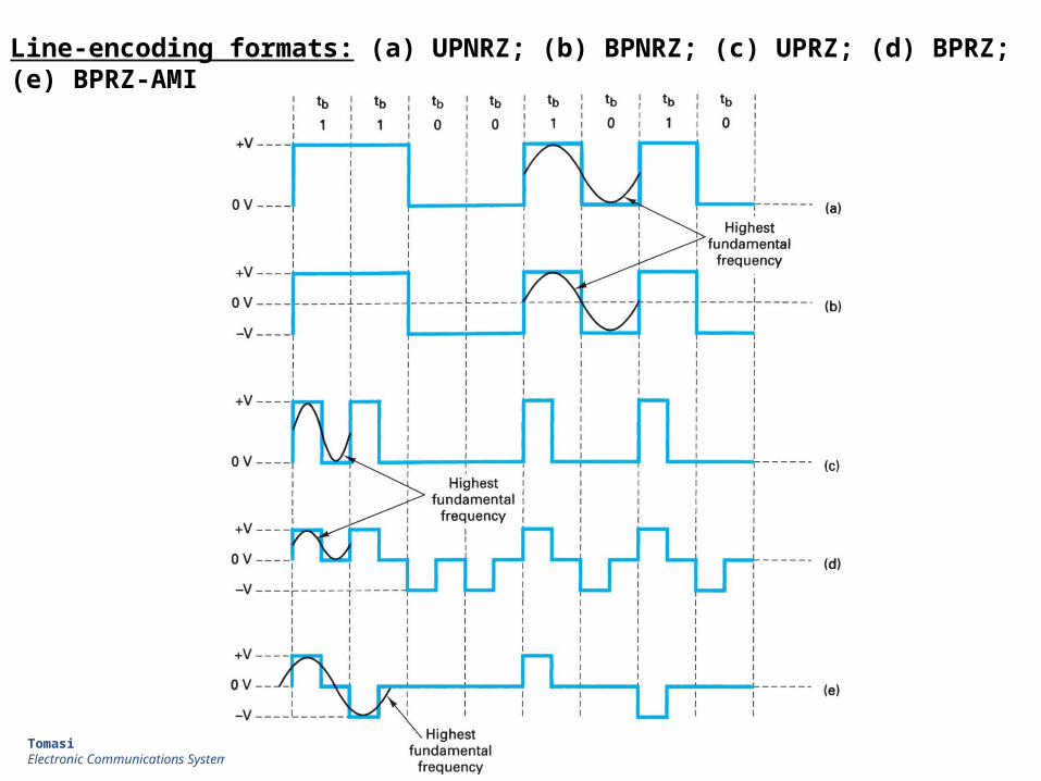
Line-encoding formats: (a) UPNRZ; (b) BPNRZ; (c) UPRZ; (d) BPRZ; (e) BPRZ-AMI
TomasiElectronic Communications Systems, 5e

Line-Encoding Summary
TomasiElectronic Communications Systems, 5e

11-3: Transmission Efficiency
Hartley’s Law The amount of information that can be sent in a given
transmission is dependent on the bandwidth of the communication channel and the duration of transmission.
Mathematically, Hartley’s law is
C = 2B
where C is the channel capacity (bps) and B is the channel bandwidth.
Hartley’s law for multiple coding levels
C = 2B log2N
where N is the number of different encoding levels per time interval.

Transmission Media and Bandwidth
The two types of wire cable: Coaxial cable has a center conductor surrounded by an
insulator over which is a braided shield. The entire cable is covered with a plastic insulation.
A twisted-pair cable is two insulated wires twisted together.

11-4: Basic Modem Concepts
Digital data are transmitted over the telephone and cable television networks by using broadband communication techniques involving modulation, which are implemented by a modem, a device containing both a modulator and a demodulator.
Modems convert binary signals to analog signals capable of being transmitted over telephone and cable TV lines and by radio, and then demodulate such analog signals, reconstructing the equivalent binary output.

There are four widely used modem types:1. Conventional analog dial-up modems.2. Digital subscriber line (DSL) modems.3. Cable TV modems.4. Wireless modems.
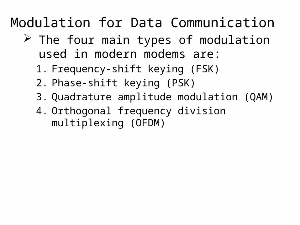
Modulation for Data Communication The four main types of modulation used in
modern modems are:1. Frequency-shift keying (FSK)
2. Phase-shift keying (PSK)
3. Quadrature amplitude modulation (QAM)
4. Orthogonal frequency division multiplexing (OFDM)

TomasiElectronic Communications Systems, 5e
Copyright ©2004 by Pearson Education, Inc.Upper Saddle River, New Jersey 07458
All rights reserved.
(a) Binary signal (b) FSK signal

Noncoherent FSK demodulator
TomasiElectronic Communications Systems, 5e
Copyright ©2004 by Pearson Education, Inc.Upper Saddle River, New Jersey 07458
All rights reserved.

Figure 11-18: Binary phase-shift keying

BPSK modulator: (a) truth table; (b) phasor diagram; (c) constellation diagram
TomasiElectronic Communications Systems, 5e
Copyright ©2004 by Pearson Education, Inc.Upper Saddle River, New Jersey 07458
All rights reserved.

BPSK transmitter
TomasiElectronic Communications Systems, 5e
Copyright ©2004 by Pearson Education, Inc.Upper Saddle River, New Jersey 07458
All rights reserved.
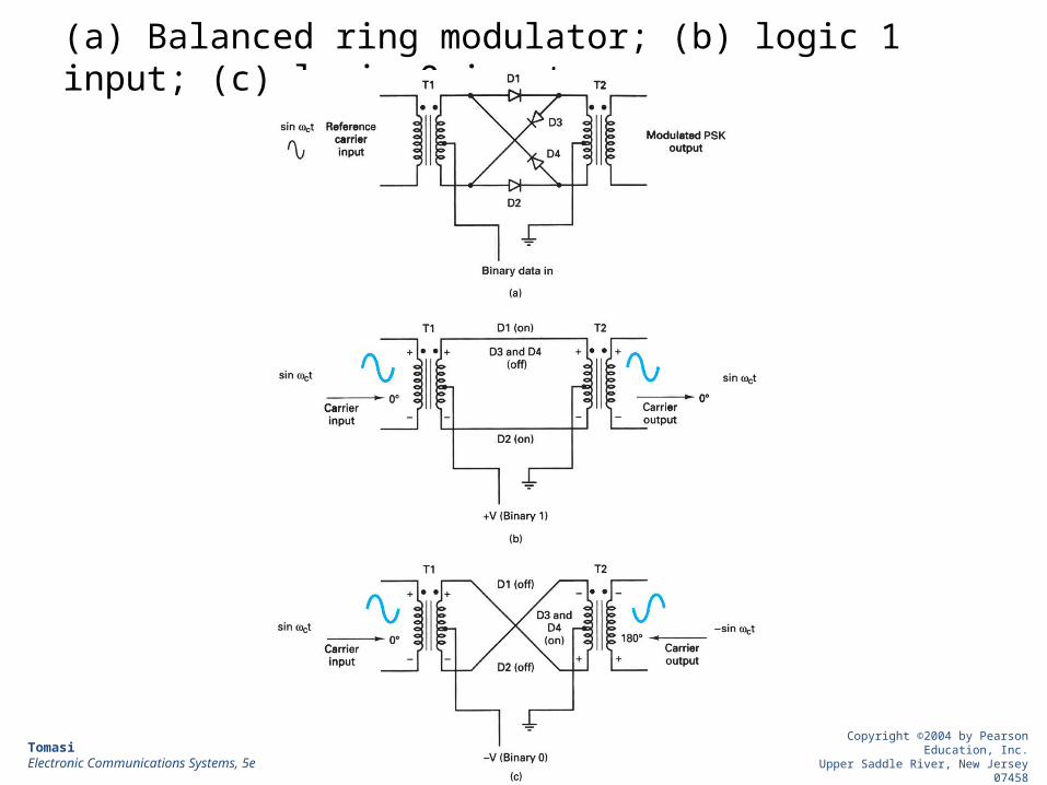
(a) Balanced ring modulator; (b) logic 1 input; (c) logic 0 input
TomasiElectronic Communications Systems, 5e
Copyright ©2004 by Pearson Education, Inc.Upper Saddle River, New Jersey 07458
All rights reserved.

QPSK modulator: (a) truth table; (b) phasor diagram; (c) constellation diagram
TomasiElectronic Communications Systems, 5e
Copyright ©2004 by Pearson Education, Inc.Upper Saddle River, New Jersey 07458
All rights reserved.

QPSK modulator
TomasiElectronic Communications Systems, 5e
Copyright ©2004 by Pearson Education, Inc.Upper Saddle River, New Jersey 07458
All rights reserved.

Modulation for Data Communication: QAM
One of the most popular modulation techniques used in modems for increasing the number of bits per baud is quadrature amplitude modulation (QAM).
QAM uses both amplitude and phase modulation of a carrier.
In 8-QAM, there are four possible phase shifts and two different carrier amplitudes.
Eight different states can be transmitted.With eight states, 3 bits can be encoded for each
baud or symbol transmitted.Each 3-bit binary word transmitted uses a different
phase-amplitude combination.

Figure 11-29: A constellation diagram of a QAM signal.

Spectral Efficiency and NoiseSpectral efficiency is a measure of how fast data can
be transmitted in a given bandwidth (bps/Hz).Different modulation methods give different
efficiencies.
Modulation Spectral efficiency, bps/Hz
FSK <1
BPSK 1
QPSK 2
8-PSK 3
16-QAM 4

Spectral Efficiency and Noise (cont.)
The signal-to-noise (S/N) ratio clearly influences the spectral efficiency.
The greater the noise, the greater the number of bit errors.
The number of errors that occur in a given time is called the bit error rate (BER).
The BER is the ratio of the number of errors that occur to the number of bits that occur in a one second interval.

When high-speed binary data is transmitted over a communication link errors will occur.
These errors are changes in the bit pattern caused by interference, noise, or equipment malfunctions.
The number of bit errors that occur for a given number of bits transmitted is referred to as the bit error rate (BER).
11-7: Error Detection and Correction

Example 11-3
Data is transmitted in 512-byte blocks or packets. Eight sequential packets are transmitted. The system BER is 2: 10,000 or 2 X 10⁻⁴. On average, how many errors can be expected in this transmission?
Solution: 8 packets X 512 bytes = 4096 bytes 4096 bytes X 8 bits = 32,768 bits Average number of errors = 32,768 x (2 x 10-4) = 6.5536

The process of error detection and correction involves adding extra bits to the data characters to be transmitted. This process is generally referred to as channel encoding.
Error Detection and Correction (cont.)
The data to be transmitted is processed in a way that creates the extra bits and adds them to the original data. At the receiver, these extra bits help in identifying any errors that occur in transmission caused by noise or other channel effects.
Channel encoding methods fall into to two separate categories, error detection codes and error correction codes.

Error Detection One of the most widely used systems is known as parity, in
which each character transmitted contains one additional bit, known as a parity bit.
The cyclical redundancy check (CRC) is a mathematical technique used in synchronous data transmission that effectively catches 99.9 percent or more of transmission errors.

Figure 11-51 A parity generator circuit
Odd parity: 10110011 00101001
Even parity 10101001 00110011
1
11
11
000
0
0
1
0
1
1
1
Error Correction: Block-Check Character The block check character (BCC) is also known as a
horizontal or longitudinal redundancy check (LRC). It is the process of logically adding, by exclusive-ORing,
all the characters in a specific block of transmitted data. The final bit value for each horizontal row becomes one
bit in a character known as the block-check character (BCC).

Figure 11-54 Vertical and horizontal redundancy checks
(even)
0