11 mile6 00 -...
TRANSCRIPT

1
Model: 202308/202310/202312Lit. #: 98-1513/12-12 ENGLISH
160016001 MILE

4
Fusion™ 1 Mile ARC™ - Laser Rangefinder Binocular202308 / 202310 / 202312
An advanced Fusion of our finest technologies.
The ultimate in efficiency, our new Fusion 1 Mile ARC melds the best of Bushnell binoculars with world-leading laser rangefinding capabilities. Every detail is magnified with rich contrast and stunning clarity from edge to edge using premium fully multi-coated optics and BaK4 prisms. At the push of a button, it displays the exact distance to your target from 10 yards to 1 mile. With built-in Angle Range Compensation, BOW Mode delivers Line-of-sight, degree of angle, and true horizontal distance and RIFLE Mode provides line-of-sight, degree of angle, and bullet-drop / hold-over data. With new Matrix Display Technology™, RainGuard® HD anti-fog coating and a fully waterproof design to ensure reliability and clarity in all conditions, it’s the best of all worlds.
This booklet will help you achieve optimum performance by explaining its adjustments and features as well as how to care for this device. To ensure optimal performance and longevity, please read these instructions before using you’re Fusion 1 Mile ARC™ laser rangefinder.

5
HOW OUR DIGITAL TECHNOLOGY WORKSThe Fusion™ 1 Mile ARC™ emits invisible, eye safe, infrared energy pulses. The Fusion 1 Mile ARC‘s Advanced Digital microprocessor and ASIC chip (Application-Specific Integrated Circuit) results in instantaneous and accurate readings every time. Sophisticated digital technology instantaneously calculates distances by measuring the time it takes for each pulse to travel from the rangefinder, to the target, and back.
RANGING ACCURACYThe ranging accuracy of the Fusion 1 Mile ARC is plus or minus one yard / meter under most circumstances. The maximum range of the instrument depends on the reflectivity of the target. The maximum distance for most objects is 1000 yards / 914 meters while for highly reflective objects the maximum is 1 mile / 1600 meters. Note: You will get both longer and shorter maximum distances depending on the reflective properties of the particular target and the environmental conditions at the time the distance of an object is being measured.
The color, surface finish, size and shape of the target all affect reflectivity and range. The brighter the color, the longer the range. White is highly reflective, for example, and allows longer ranges than the color black, which is the least reflective color. A shiny finish provides more range than a dull one. A small target is more difficult to range than a larger target. The angle to the target also has an effect. Shooting to a target at a 90 degree angle (where the target surface is perpendicular to the flight path of the emitted energy pulses) provides good range while a steep angle on the other hand, provides limited ranging. In addition, lighting conditions (e.g. the amount of sunlight) will affect the ranging capabilities of the unit. The less light (e.g. overcast skies) the farther the unit’s maximum range will be. Conversely, very sunny days will decrease the unit’s maximum range.

6
GETTING STARTED
INSERTING THE BATTERYThe battery compartment is located between the objective barrels. Simply remove the battery cap by rotating it counter clockwise and insert a CR-123 3-volt lithium battery into the compartment negative end first, then replace the battery cap.
NOTE: It is recommended that the battery be replaced at least once every 6 months.
SETTING THE DISPLAY FOCUS AND DIOPTER ADJUSTMENT Before you begin using your laser rangefinder binoculars, a few simple, one-time adjustments should be made to ensure that you can get sharp focus of objects by just using the main focus knob on the binoculars. This process will compensate for any variations in the eyesight or vision of the individual user:
1. Leave the rubber eyecups in their “up” position if you are not wearing glasses, or twist them down if you are. Grasp the left and right sides of the binocular, and pull them apart or push them together while looking through the binocular to adjust the eyepiece spacing until your view is a single circular image.
2. While looking through the binoculars, press the power button to turn on the display. Look through just the right side of the binocular-you will see a red aiming circle in the center. Point the binocular at a plain background. 3. Rotate the display focus (right eyecup) until the circular reticle appears as sharp as possible to your right eye. This compensates for any difference between your vision and the correct focus for the laser. 4. Next, continuing to look through the right side only, aim at a distant object (preferably one containing fine detail such as a tree or sign), and adjust the binocular’s center focusing knob until it appears as sharp as possible to your right eye.

7
5. Finally, view the same object through only the left side of the binocular, and rotate the diopter adjustment (left eyecup) until it appears sharp to your left eye (do not touch the center focus knob while doing this). This compensates for any vision differences between your left and right eyes.
Once set, note the number on the left and right binocular tubes that the index mark on each eyecup is lined up with. With the display focus and diopter adjustment set to these positions, you should be able to obtain sharp viewing of objects at any distance by simply adjusting the center focus knob while you look through the binocular. There is no need to re-adjust the display focus or diopter adjustment, unless you share the binocular with another user, or if your eyes become tired over a long period of use. OPERATIONAL SUMMARY While looking through the binocular, depress the power button once to activate the Matrix Display. Place the aiming circle (located in the center of the field of view) upon a target at least 10 yards away, depress and hold the power button down until the range reading is displayed near the bottom of the in-view display. Crosshairs surrounding the aiming circle indicate that the laser is being transmitted. Once a range has been acquired, you can release the power button. The crosshairs surrounding the aiming circle will disappear once the power button has been released (i.e. the laser is no longer being transmitted). Note: Once activated, the display will remain active and display the last distance measurement for 3 seconds. You can depress the power button again at any time to distance to a new target. As with any laser device, it is not recommended to directly view the emissions for long periods of time with magnified lenses. The maximum time the laser is transmitted (fired) is 10 seconds. To re-fire, press the button down again.
Matrix DISPLAY INDICATORSYour Fusion 1 Mile ARC Matrix Display™ incorporates the following illuminated indicators:

8
3
12
6
7
89
5
Angle Range Compensation Modes Rifle ( ) or Bow ( ) Mode (1)
Battery Life Indicator (2)
Aiming Circle (3)
Targeting Modes BullsEye ( ) or Brush ( ) Mode (5)
Primary Numeric Display (displays Line-of-sight Distance) (6)
Holdover / Bullet-drop measure for Rifle Mode Units (IN, CM, MOA or mil) (7) Variable Sight-In Distance (8)
Secondary Numeric Display (9) (Toggles from Degree of Angle to Holdover / bullet drop for Rifle mode) (Toggles from Degree of Angle to True Horizontal Distance for Bow Mode)

9
ANGLE RANGE COMPENSATION The Fusion 1 Mile ARC is an advanced premium laser rangefinder binocular featuring a built-in accelerometer-based inclinometer that digitally displays the exact angle from -90 to +90 degrees of elevation and is +/- 1.0 degree accurate. The Bushnell® Fusion 1 Mile ARC™ solves a problem hunters have been faced with for years. The problem: Bow and rifle hunters have struggled with extreme uphill and downhill angles because of how these angles alter true horizontal distance to your target. The Solution: ARC’s integrated inclinometer provides elevation angle to allow for distance compensation when targeting objects that are either uphill or downhill. This data is then combined with internal algorithmic ballistic formulas.
ARC (ANGLE RANGE COMPENSATION) MODESBow Mode ( ): Displays line of sight distance, degree of elevation, and true horizontal distance from 10-99 yards / meters and a maximum inclination of +/- 90°.
Rifle Mode ( ): Calculates and displays the amount of bullet drop, at the target in inches, centimeters, MOA or MIL. The amount of bullet drop is determined by the line of sight distance to the target, degree of elevation, along with the specific ballistic characteristics of the caliber and ammunition load. When you range your target, the line of sight, degree of elevation, and bullet-drop/holdover in inches, centimeters, MOA or MIL will be displayed from 100 to 800 yards/meters with a maximum inclination of +/- 90°. One of eight ballistic groups (identified as A, B, C, D, E, F, G, and H) for center fire rifles and two ballistic groups (Identified as I and J) for Black Powder / Muzzleloaders can be selected by the user, with each formula representing a given combination of caliber and loads. The ballistic groups are selected by the user in the SET-UP menu.
Regular Mode (ARC OFF): This mode does not provide any degree of elevation or compensated distance, but instead, line of sight distance only.

10
BATTERY LIFE INDICATORBattery Indicator:
Full charge 1/2 battery life remaining Very low charge level (not blinking) Battery Indicator Blinks - Battery needs to be replaced and unit will not be operable.
UNIT OF MEASURE OPTIONS The Fusion 1 Mile ARC can be used to measure distances in yards or meters. The unit of measure indicators are located in the lower right portion of the Matrix Display.
ACTIVE LASER Crosshairs surrounding the aiming circle indicate that the laser is being transmitted. Once a range has been acquired, you can release the power button. The crosshairs surrounding the circle will disappear once the power button has been released (i.e. the laser is no longer being transmitted). SELECTIVE TARGETING™ MODES The Fusion 1 Mile ARC was especially designed with hunters in mind. The selective targeting modes allow you to adjust the performance parameters of the unit to suit your specific situation and environment. To move from one mode to another, press the POWER button once to turn on the unit. While looking through the eyepiece, press the MODE button and quickly release. The different targeting modes available and mode indicators are listed below:
Standard with Automatic SCAN (Display Indicator – none) This setting allows most targets to be distanced up to 1760 yards. Used for moderately reflective targets that are typical of most distancing situations. The minimum

11
distance in the standard mode is 10 yards. To use the Automatic SCAN feature, simply hold down on the POWER button for approximately 3 seconds and move the rangefinder from object to object while leaving the POWER button depressed. Automatic SCAN will allow the range to be continuously updated as multiple objects are targeted.
BullsEye™ (Display Indicator - ) This advanced mode allows easy acquisition of small targets and game without inadvertently getting distances to background targets that have stronger signal strength. When more than one object has been acquired, distance of the closer object will be displayed and a crosshair will surround the BullsEye™ indicator informing the user that distance to the closer object is being displayed.Once in this mode, press the POWER button to turn the unit on. Next, align the aiming circle onto the object (i.e. deer) that you want distance to. Next, press and hold the POWER button and move the laser slowly over the deer until crosshairs surround the BullsEye indicator. If the laser beam recognized morethan one object (i.e. deer and background trees), distance of the closer object (i.e. deer) will be displayed and crosshairs will surround the BullsEye indicator informing the user that distance to the closer object is being displayed (Figure 1). There may be times when only the laser beam only sees one object in its path. In this case, the distance will be displayed, but because more than one object was not acquired, crosshairs will not surround the BullsEye indicator.
Figure 1
12
TIP: While pressing the POWER button, you can move the device slowly from object to object and intentionally force the laser to hit multiple objects to ensure that you are only displaying the closest of the objects recognized by the laser.
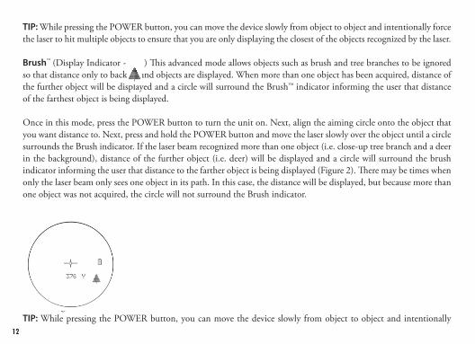
Brush™ (Display Indicator - ) This advanced mode allows objects such as brush and tree branches to be ignored so that distance only to background objects are displayed. When more than one object has been acquired, distance of the further object will be displayed and a circle will surround the Brush™ indicator informing the user that distance of the farthest object is being displayed.
Once in this mode, press the POWER button to turn the unit on. Next, align the aiming circle onto the object that you want distance to. Next, press and hold the POWER button and move the laser slowly over the object until a circle surrounds the Brush indicator. If the laser beam recognized more than one object (i.e. close-up tree branch and a deer in the background), distance of the further object (i.e. deer) will be displayed and a circle will surround the brush indicator informing the user that distance to the farther object is being displayed (Figure 2). There may be times when only the laser beam only sees one object in its path. In this case, the distance will be displayed, but because more than one object was not acquired, the circle will not surround the Brush indicator.
Figure 2TIP: While pressing the POWER button, you can move the device slowly from object to object and intentionally

13
force the laser to hit multiple objects to ensure that you are only displaying the furthest of the objects recognized by the laser.
Once the device has shut off, the unit will always default back to the last targeting mode used.
MENU SETUP – SELECTION OF DISPLAY BRIGHTNESS, BOW, RIFLE, REGULAR MODES, UNIT OF MEASURE, SIGHT-IN DISTANCE AND BALLISTIC CORRECTION
DISPLAY BRIGHTNESS
Matrix Display Technology™ dramatically improves contrast, clarity and light transmission while increasing brightness of the digital readout, making distance readings legible in low light environments.
There are four intensity settings to choose from and this is the first setting within the SETUP menu. Press the MODE button for 3 seconds to get into the SETUP menu. The existing brightness setting will be flashing (i.e. BRIGHT 1, BRIGHT 2, BRIGHT 3, or BRIGHT 4), pressing the MODE button will toggle between the four brightness settings. “ BRIGHT 1” is the lowest intensity while “BRIGHT 4” is the brightest.
Simply press the MODE button until the desired brightness setting is displayed and select by pressing and releasing the POWER button.
There are two ARC (Angle Range Compensation) modes and one REGULAR mode. The two ARC modes are BOW mode and RIFLE mode.
To select between these modes, first turn the unit “ON” by pressing and releasing the POWER button. Next, press

14
and hold the MODE button for three seconds to get into the SETUP menu. The brightness is displayed first and can be changed by pressing the MODE button or accepted by pressing the POWER button. Then press the power button until you see the existing compensation mode indicated by either the “Bow” symbol ( ), the “Rifle” symbol ( ) lit with one of the ballistic groups (A thru J) displayed and flashing, or no indicators lit and the message (ARC OFF) flashing.
The modes can be cycled through in a circular fashion by pressing and releasing the mode button. The order of modes is a follows: BOW, RIFLE A, RIFLE B, RIFLE C, RIFLE D, RIFLE E, RIFLE F, RIFLE G, RIFLE H, RIFLE I, RIFLE J, REG, etc. When the bow selection is displayed, the “BOW” icon will flash and when a “RIFLE: selection is displayed, the “RIFLE” icon and ballistic group will be flashing. When the (ARC OFF) is displayed, the message (ARC OFF) will flash within the display.
Once the desired distance compensation mode is displayed, select it by pressing and releasing the POWER button. Following this selection, the current unit of measure, “Y” for yards or “M” for meters will flash in the display and the SETUP icon is still lit. Pressing the MODE button will toggle the unit of measure. When the desired unit of measure is displayed, press the POWER button to accept the unit of measure.
If the user chooses RIFLE mode, and after having determined unit of measure, the user has the following options:
1. Variable Sight-In (VSI™) - Allows the rifle hunter to choose from four sight-in distances (100, 150, 200, or 300 yards or meters) and provides holdover / bullet-drop data in inches, centimeters, MOA or MIL. The “SD” (Sight-In Distance) indicator will turn on and the current Sight-In Distance number will blink within the display (I.e. 100, 150, 200, or 300). The Sight-In Distance options can be cycled through in a circular fashion by pressing and releasing the mode button. Once the desired Sight-In Distance is displayed, select it by pressing and releasing the power button. 2. And finally, if RIFLE mode was chosen, and as long as unit of measure and a sight-in distance was selected, you

15
have the option of determining how you would like hold-over / bullet-drop displayed. If measurement units are in yards, you will be able to choose between inches, MOA or MIL. The “CM” for centimeters or “IN” for inches will flash in the display and the SETUP icon is still lit. Once the desired ballistic measure is displayed, select it by pressing and releasing the power button. If units of measure selected previously was Meters, then your hold-over / bullet-drop will automatically be displayed in centimeters.
Upon returning to the normal operating menu, the current compensation mode and unit of measure will be identified in the display as indicated below.
SETUP menu Normal Operating Menu

16
When the unit automatically powers down, operation will always return to the normal operation (i.e. away from SETUP) with the last used ARC mode active (i.e. BOW, RIFLE, or REGULAR) along with the last used TARGETING modes active (Standard SCAN, BULLSEYE, or BRUSH). If the unit turns off while in the SETUP menu, the unit will always return to the last mode(s) still active.
Once the range is displayed, continue to hold the POWER button down for approximately 2 seconds while holding the aiming circle on the object and keeping the unit as steady as possible so as to allow the inclinometer enough time to measure angle. Then release the POWER button. Once you have released the power button, the line of sight will be displayed along with unit of measure. Beneath the line of sight distance and unit of measure, the degree of angle will be displayed for approximately 1.5 seconds, and will then automatically switch to the compensated range. The line of sight distance, unit of measure and automatic toggle from degree of angle to compensated distance will continue for 5 seconds at which time the display will automatically shut off.
BOW MODE EXAMPLELine of sight is 32 yards, angle is -44 degrees, and the Angle Range Compensated distance is 23 yards. Instead of shooting as 32 yards, shoot as 23 yards. If you were to shoot as if 32 yards, you would shoot over the top of the deer because of the severe angle.
Line of Sight = 32YDegree of Angle = -44°Compensated Distance = 23Y

17
If in BOW mode, the line of sight distance will display in the primary numeric display and the inclination and horizontal distance will display in the secondary numeric displays. Bushnell determined through extensive testing and interviews with high-profile bow hunting experts that multiple bow ballistic groups were not necessary. Bow-hunters want to know true horizontal distance because that is how they practice shooting, and once they confidently know that, they can make any necessary adjustments. Giving the bow-hunter anything else other than horizontal distance creates additional confusion and uncertainty.
Many people mistakenly believe that uphill shots perform differently from downhill shots because of gravity. However, it is not due to gravity, but more of an aberration of the sighting system used on bows. The sighting pin on a bow resides several inches above the mechanical axis of the arrow. For example, when one is aiming 23 degrees up an incline, the arrow is at a different angle.
RIFLE MODE EXAMPLELine of sight is 376 yards, angle is -33 degrees, and the bullet-drop/holdover is 28 inches. ARC not only takes into account ballistic data based off your caliber and load from distances of 100-800 yards, but also compensates for any uphill and downhill angles which also affect bullet-drop.
Line of Sight = 376 YardsDegree of Angle = -33°Holdover/Bulletdrop = 28 Inches

18
If in RIFLE mode, the ballistic group will be displayed in the bullet drop numeric field anytime that the primary numeric display is showing dashes (i.e. no target acquired). When a target is acquired in RIFLE mode, the line of sight distance will display in the secondary numeric displays. The “IN” icon (i.e. inches) will light next to the bullet drop numeric display, if the unit of measure is set to Yards (Y). If the unit of measure is set to Meters (M), the bullet drop will be calculated and displayed in centimeters and the “IN” icon will be turned off. If the bullet drop / hold over reads “ ,” this means the compensated distance is beyond what can be displayed, and or beyond ballistic calculations and user will need to hold low.
REGULAR MODE (ARC OFF)This mode does not provide any degree of elevation or compensated distance, but instead, line of sight distance only. The secondary display will still appear below the line of sight numeric display, but there will not be any information displayed in this secondary numeric display.
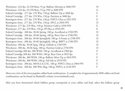
KNOWING WHICH BALLISTIC GROUP TO SELECTBushnell engineers have worked with Sierra® Bullets’ ballistic programs and grouped many of the most popular calibers and loads into eight ballistic groups (A,B,C,D,E,F,G,H). Once you know what caliber and load you are shooting simply look through the chart to determine which one of the eight ballistic groups match with your particular load and caliber. For Muzzleloaders, we have worked with PowerBelt Bullets to incorporate ballistic data into two ballistic groups (I and J).
POPULAR CALIBER & LOAD COMBINATIONS Federal Cartridge.224 dia. 22-250 Rem, 55 gr. Bear Claw at 3600 fps GFederal Cartridge.224 dia. 22-250 Rem, 60 gr. Partition at 3500 fps FRemington Arms .224 dia. 22-250 Remington Arms , 50 gr. V-Max at 3725 FPS HRemington Arms .224 dia. 22-250 Remington Arms , 55 gr. PSP at 3680 FPS G
19
Winchester .224 dia. 22-250 Rem, 55 gr. Ballistic Silvertip at 3680 FPS HWinchester .224 dia. 22-250 Rem, 55 gr. PSP at 3680 FPS GFederal Cartridge .277 dia. 270 Win, 150 gr. Ballistic Tip at 3060 fps FFederal Cartridge .277 dia. 270 Win, 150 gr. Partition at 3000 fps FRemington Arms .277 dia. 270 Win, 140 gr. PSPCL Ultra at 2925 FPS ERemington Arms .277 dia. 270 Win, 150 gr. SPCL at 2850 FPS DWinchester .277 dia. 270 Win, 150 gr. Partition Gold at 2930 FPS EWinchester .277 dia. 270 Win, 150 gr. PP-Plus at 2950 FPS EFederal Cartridge .308 dia. 30-06 Spring, 180 gr. AccuBond at 2700 FPS DFederal Cartridge .308 dia. 30-06 Spring, 180 gr. Bear Claw at 2700 FPS DRemington Arms .308 dia. 30-06 Springfield, 180 gr. A-Frame at 2700 FPS DRemington Arms .308 dia. 30-06 Springfield, 180 gr. BRPT at 2700 FPS DWinchester .308 dia. 30-06 Sprg, 180 gr. FailSafe at 2700 FPS DWinchester .308 dia. 30-06 Sprg, 180 gr. Partition Gold at 2750 FPS DFederal Cartridge.308 dia. 300 WSM, 180 gr. AccuBond at 2960 fps FFederal Cartridge.308 dia. 300 WSM, 180 gr. Bear Claw at 3025 fps FWinchester .308 dia. 300 WSM, 180 gr. Ballistic Silver Tip at 3010 FPS FWinchester .308 dia. 300 WSM, 180 gr. Fail Safe at 2970 FPS FRemington Arms .308 dia. 300 R.S.A.U.M., 180 gr. PSPCL Ultra at 2960 FPS ERemington Arms .308 dia. 300 Wby Mag, 180 gr. PSPCL at 3120 FPS F
Above are a few of the most popular caliber/load combinations. A complete list of approximately 2000 caliber and load combinations can be found on Bushnell’s website (www.bushnell.com).
After you have determined which ballistic group corresponds to your caliber and load, select this ballistic group

20
(See MENU SETUP above). The internal formula will determine amount of bullet drop/holdover in inches or centimeters based upon distance, angle, and ballistics of your caliber and load.This state-of-the-art digital technology allows the hunter or shooter to know precisely where to hold for an effective shot. This information should be treated as a helpful guide or tool and in no way should it ever replace practice and familiarity with your rifle, cartridge and load. We encourage practice shooting at different ranges so you know how your rifle, cartridge and load will perform under various conditions. Always know what is behind your bullet; if you don’t know, don’t take the shot.
EXAMPLEYou have a 300 WSM and are shooting the following Winchester brand load: 180 gr. Ballistic Silver Tip bullet at 3010 FPS muzzle velocity. This combination falls under Ballistic Group “F”. After setting the rangefinder to ballistic group “F”, go to the range and sight in your riflescope at 100 yards. If you then take a shot at a target at 317 yds, the bullet drop will be 9 inches. If the shot is at angle of 27 degrees upward, then the corrected bullet drop will be 8 inches.
WHAT IF YOUR CALIBER IS NOT LISTED?While we have taken great care to include as many calibers and brand names in our ballistics tables, new loads are always being developed. In addition, some shooters load their own ammunition with unique ballistic characteristics. If you cannot find your load in our ballistic tables, you can still use the bullet drop feature of the laser rangefinder. As above, sight in your rifle at 100 yds. Then shoot the rifle, without adjusting the riflescope, at 300 yds. Measure the bullet drop from the point of aim. Using this drop, select the ballistic group from below. If you will be shooting longer distances then you may want to check the bullet drop at 500 yds. Because there is enormous variation in rifle barrels, chambers, and hand loads, you should thoroughly test the ballistic setting before actual hunting. You may need to move up or down one group depending upon your tests.

21
BULLET DROP
Use: @300 yds @300 m @500 yds @500 m
A 25-31 inches 63-79 cm 114-146 inches 291-370 cm
B 20-25 inches 50-63 cm 88-114 inches 225-291 cm
C 16-20 inches 40-50 cm 72-88 inches 182-225 cm
D 13-16 inches 34-40 cm 61-72 inches 155-182 cm
E 12-13 inches 30-34 cm 55-61 inches 139-155 cm
F 10-12 inches 25-30 cm 47-55 inches 119-139 cm
G 8-10 inches 20-25 cm 39-47 inches 99-119 cm
H Less than 8 inches Less than 20 cm Less than 39 inches Less than 99 cm

22
OPTICAL DESIGN The Fusion 1 Mile ARC features 8x/10x/12x magnification and fully multi-coated optics and also includes:
PC-3® PHASE COATINGBaK-4 glass roof prisms which are then phase corrected with our proprietary PC-3® phase coating. This compensates for phase shifts of light rays to deliver the pinnacle of razor-sharp clarity and resolution.
XTR® TECHNOLOGYThe ultimate optical performance enhancer, this Bushnell-exclusive technology employs multiple layers of anti-reflective coatings to maximize light transmission
RAINGUARD® HDThe outer surfaces of the objective and eyepiece lenses are coated with RainGuard® HD. RainGuard® HD is Bushnell’s permanent, patented, hydrophobic (water repellant) lens coating that prevents fogging by causing condensation from rain, sleet, snow or even your own breath to bead up into much smaller droplets than on standard coatings. Smaller uniform droplets scatter less light which results in a clearer, brighter view.

23
CLEANINGGently blow away any dust or debris on the lenses (or use a soft lens brush). To remove dirt or fingerprints, clean with a soft cotton cloth, rubbing in a circular motion. Use of a coarse cloth or unnecessary rubbing may scratch the lens surface and eventually cause permanent damage. For a more thorough cleaning, photographic lens tissue and photographic-type lens cleaning fluid or isopropyl alcohol may be used. Always apply the fluid to the cleaning cloth – never directly on the lens.
SpecificationS 8x32 10x42 12x50
Weight 30.8 oz 31 oz 32.7oz
Ranging Accuracy +/- 1 yard
Range 10yds-1 mile / 10-1600 meters
Magnification 8x 10x 12x
Objective Diameter 32 mm 42 mm 50 mm
Optical Coatings Fully Multi-Coated
RainGuard HD Coating Yes
Display Red Matrix Display
Power Source 3-volt lithium (CR-123)
Field Of View377 ft @ 1000 yds /
126m @ 1000m305 ft @ 1000 yds / 101 m @ 1000 m
252 ft @ 1000 yds / 84 m @ 1000 m
Long Eye Relief 18 mm 18 mm 16 mm
Exit Pupil 4.0 mm 4.2 mm 4.2 mm
Waterproof Yes
Included Accessories Battery, Carrying Case, Strap

24
TWO-YEAR LIMITED WARRANTY
Your Bushnell® product is warranted to be free of defects in materials and workmanship for two years after the date of purchase. In the event of a defect under this warranty, we will, at our option, repair or replace the product, provided that you return the product postage prepaid. This warranty does not cover damages caused by misuse, improper handling, installation, or maintenance provided by someone other than a Bushnell Authorized Service Department.
Any return made under this warranty must be accompanied by the items listed below:1. A check/money order in the amount of $10.00 to cover the cost of postage and handling2. Name and address for product return3. An explanation of the defect4. Proof of Date Purchased5. Product should be well packed in a sturdy outside shipping carton, to prevent damage in transit,
with return postage prepaid to the address listed below:
IN U.S.A. Send To: IN CANADA Send To: Bushnell Outdoor Products Bushnell Outdoor Products Attn.: Repairs Attn.: Repairs 9200 Cody 25A East Pearce Street, Unit 1 Overland Park, Kansas 66214 Richmond Hill, Ontario L4B 2M9
For products purchased outside the United States or Canada please contact your local dealer for applicable warranty information.
In Europe you may also contact Bushnell at: BUSHNELL Outdoor Products Gmbh European Service Centre Mathias-Brüggen-Straße 80 D-50827 Köln GERMANY Tél: +49 (0) 221 995 568 0 Fax: +49 (0) 221 995 568 20
This warranty gives you specific legal rights. You may have other rights which vary from country to country.
©2012 Bushnell Outdoor Products

25
TROUBLE SHOOTING TABLE If unit does not turn on - LCD does not illuminate:
• DepressPOWERbutton.• Checkandifnecessary,replacebattery.
If unit powers down (display goes blank when attempting to power the laser):•Thebatteryiseitherweakorlowquality.Replacethebatterywithagoodquality3-voltlithiumbattery(CR-123).
If target range cannot be obtained:•MakesureDisplayisilluminated.•Makesurethatthepowerbuttonisbeingdepressed.•Makesurethatnothing,suchasyourhandorfinger,isblockingtheobjectivelenses(lensesclosesttothetarget)thatemitand receive the laser pulses.•Makesureunitisheldsteadywhiledepressingpowerbutton.
NOTE: The last range reading does not need to be cleared before ranging another target. Simply aim at the new target using the display reticle, depress the power button and hold until new range reading is displayed.
Specifications, instructions, and the operation of these products are subject to change without notice.

26
FCC NOTEThis equipment has been tested and found to comply with the limits for a Class B digital device, pursuant to Part 15 of the FCC Rules. These limits are designed to provide reasonable protection against harmful interference in a residential installation. This equipment generates, uses and can radiate radio frequency energy and, if not installed and used in accordance with the instructions, may cause harmful interference to radio communications. However, there is no guarantee that interference will not occur in a particular installation. If this equipment does cause harmful interference to radio or television reception, which can be determined by turning the equipment off and on, the user is encouraged to try to correct the interference by one or more of the following measures:
• Reorientorrelocatethereceivingantenna.• Increasetheseparationbetweentheequipmentandreceiver.• Connect the equipment into an outlet on a circuit different from that to which the receiver is connected. • Consultthedealeroranexperiencedradio/TVtechnicianforhelp.
Shielded interface cable must be used with the equipment in order to comply with the limits for a digital device pursuant to Subpart B of Part 15 of FCC Rules.
Specifications and designs are subject to change without any notice or obligation on the part of the manufacturer
FDA SAFETYClass 1 laser product in accordance with IEC 60825-1:2007.Complies with 21 CFR 1040.10 and 1040.11 for laser products except for deviations pursuant to Laser Notice No. 50, dated June 24, 2007.
Caution: There are no user controls, adjustments or procedures. Performance of procedures other than those specified herein may result in access to invisible laser light.