11 - freeit.free.frfreeit.free.fr/knovel/strengthening of reinforced concrete... · both the design...
TRANSCRIPT

288 Strengthening of reinforced concrete structures
288
11Case studies of carbon fibre bonding
worldwide
M A SHAW AND J F DREWETT
11.1 Introduction
The following case studies utilising the carbon fibre/polymer compositestrengthening concept have been incorporated into this book to illustratesome practical examples of different strengthening applications. TheROBUST project which has recently been completed has not, as yet,any proven practical examples of the strengthening of existing bridge orbuilding structures.
Sika Ltd, Hertfordshire, UK, one of the members of the ROBUST Con-sortium, has developed over a number of years a procedure for strengthen-ing, using a system approach comprising an advanced epoxy structuraladhesive and a range of carbon fibre/epoxy polymer laminates. This com-bined system is known as the Sika CarboDur system.
Sika have been in the forefront of structural adhesive engineering in theconstruction industry for many years. Structural adhesives have been spe-cifically developed to transfer stresses from one substrate to another for arange of different situations. Typical applications include segmental bridgeconstruction and strengthening structures using external plate bondingtechniques. Each material has undergone intensive research and develop-ment and site trials to comply with the industry’s demands of cost effective-ness, performance and durability.
In the past external strengthening had been successfully carried out withsteel plates and epoxy-based structural adhesives. There are limitations toboth the design and practical aspects when using plates and these have beenhighlighted in the earlier chapters. Sika have been involved with over 200CarboDur projects worldwide, many of which would not have been possibleusing traditional strengthening techniques. The case histories selectedshow the adaptability and cost effectiveness of the technique and the globalacceptance of the CarboDur system.
SOR11 12/19/98, 4:24 PM288

Case studies of carbon fibre bonding worldwide 289
11.2 System properties
The general properties of the system are shown below. The carbon fibrelaminates are manufactured by the pultrusion process to the Swiss FederalLaboratories for Material Testing and Research (EMPA) specification.
11.2.1 Sika CarboDur laminates
Sika CarboDur laminates consist of:
• carbon fibre reinforced with epoxy matrix• fibre volumetric content �68%.
The laminates are available in a range of different grades. The minimumand maximum properties are shown in Table 11.1. Intermediate grades liewithin this range.
11.2.2 Structural adhesive, Sikadur 30
The properties of Sikadur 30 are
• two-part solvent free epoxy adhesive• density 1800kg/m�3
• glass transition point about 62 °C• flexural modulus 12 800 Nmm�2
• compressive strength about 90Nmm�2
• tensile strength about 30Nmm�2
• tensile slant shear strength about 18Nmm�2
• moisture uptake �0.5%.
For the case histories included in this chapter, the application of theCarboDur system has generally followed the procedure outlined below:
• The substrate surfaces were prepared to remove all contaminants.– Concrete: fine and coarse aggregate exposed and fine gripping
texture achieved by blast cleaning,
Table 11.1 Minimum and maximum properties of Sika CarboDur laminates
Minimum Maximumproperties properties
Thickness (mm) 1.2 1.4Width (mm) 50 150E-modulus (Nmm�2) 165000 300000Ultimate tensile strength (Nmm�2) 1450 3050
SOR11 12/19/98, 4:24 PM289

290 Strengthening of reinforced concrete structures
– Timber: surfaces planed or grit blasted,– Masonry: fine gripping texture achieved by blast cleaning or
scabbling.• Substrate surfaces vacuum cleaned to remove dust.• CarboDur carbon fibre laminates cut to length at factory or on site.• Preprepared laminate bonding surface cleaned.• Sikadur 30 structural adhesive applied to laminate and substrate.• Carbon fibre laminate pressed into position on substrate by hand.• Carbon fibre laminate bedded into adhesive using hard hand rubber
roller to extrude excess adhesive and produce void free bondline.• Surplus adhesive removed from substrate and laminate.
11.3 Case histories
11.3.1 Kings College Hospital, London, UK
11.3.1.1 The problem
In June 1996, this was the first project in the UK to use a carbon fibrestrengthening system for external poststrengthening. The project involvedthe overall refurbishment and extension of the Normanby College suitefor the new Joint Education Centre. As part of the refurbishment brief, anextra floor was required for accommodation. This was achieved by convert-ing the roof slab to a floor slab thereby increasing the live load capacity to3.0kN m�2. The construction of the existing building consisted of a rein-forced concrete frame with cast in situ troughed floors. The upper storeyextension was designed as a lightweight steel frame structure, howevercalculations on the existing roof slab established that in its present form, theslab could not sustain the additional live load.
To resolve the problem, three options were considered:
• Demolish the existing roof and construct a new floor.• Provide a secondary steel frame to support existing slab or new separate
floor.• Externally poststrengthen the roof slab by external plate bonding.
The first option was considered time consuming and expensive. Thesecond option was not feasible owing to the long spans. Thereforethe option of poststrengthening was preferred, based on its cost effective-ness and speed of application. The initial design showed that steel plates75mm wide and 6.0 mm thick were required to provide the additionalreinforcement.
SOR11 12/19/98, 4:24 PM290

Case studies of carbon fibre bonding worldwide 291
11.3.1.2 The solution
The original roof slab was formed from 400 mm deep tapered ribs 80mmwide at the bottom located at 600 mm centres spanning 11.0 m. Because theplate width to thickness ratio was less than 50 and it would be necessary toslice the plates for handling purposes within a restricted working area, theuse of the CarboDur strengthening system was specified by the structuralengineers, Lawrence Hewitt Partnership. To achieve the desired strength-ening requirements, the laminates used were 50 mm wide, 1.2mm thick withan E-modulus of 155 000 Nmm�2.
In competitive tender, Concrete Repairs Ltd (CRL) secured the subcon-tract to supply and install the CarboDur system for the main contractorJohn Mowlem Construction Plc.
CRL prepared the floor rib soffits by needle gunning and vacuuming;this method of preparation was checked on site by performing pull-offtests using a ‘limpet’. The pull-off values achieved were in the region of3.0 N mm�2 with a failure in the concrete. The 50 mm wide CarboDurlaminates arrived on site in 250 m long rolls, preboxed for protection (Fig.11.1). The individual laminates were then cut on site using a guillotine,cleaned to remove surface contaminants and coated with the epoxy adhesive.
At the same time the concrete bond surface was coated with adhesive(Fig. 11.2). The laminates were then offered up to the beams (Fig. 11.3) and
Figure 11.1 The complete CarboDur strengthening system.
SOR11 12/19/98, 4:24 PM291

292 Strengthening of reinforced concrete structures
Figure 11.2 Application of adhesive to CarboDur laminate.
Figure 11.3 Positioning an 11.0 m laminate to underside of rib.
SOR11 12/19/98, 4:25 PM292

Case studies of carbon fibre bonding worldwide 293
Figure 11.4 Bedding CarboDur laminate into adhesive with hand roller.
rollered into position (Fig. 11.4) to ensure good adhesive contact and toeliminate voids. The next day antipeel bolts were installed at the ends of thelaminate by drilling through the CarboDur laminate into the concrete andusing chemical anchors. The strengthening work was completed within thefour weeks programme at a cost of around £60000 using a total of 1100 m ofCarboDur laminates.
11.3.2 Strengthening of the Rhine bridge Oberriet,Meiningen, Switzerland
11.3.2.1 The problem
11.3.2.1.1 Introduction
The three span bridge was built in 1963 and crosses the border over theRiver Rhine between Austria and Switzerland, linking the towns ofMeiningen (Vorarlberg) to Oberriet (St Gallen) (Walser and Steiner,1997). The end spans are 35.1m in length with a central span of 45m(Fig. 11.5).
A thorough investigation and structural analysis according to currentSIA (Swiss Engineers and Architects) load standards had shown thatbesides normal maintenance, the bridge deck was in need of transversestrengthening. This was due to the fact that in 1963, the bridge deck hadbeen designed for standard 14 tonne truck loads.
293
SOR11 12/19/98, 4:25 PM293

294 Strengthening of reinforced concrete structures
Figure 11.5 General view of Oberriet bridge.
11.3.2.2 The solution
11.3.2.2.1 Strengthening options
Different solutions were available to guarantee the future structural safetyunder today’s traffic loads.
• replacing the entire bridge deck• improving the cross-section characteristics by providing a concrete
overlay• strengthening by bonding additional reinforcement to the existing deck.
Because the existing concrete slab was in good condition and the chloridecontent exceeded the critical values only in the outer 10mm, it was decided,for economical reasons, not to replace the total deck slab. The additionalconcrete thickness necessary to reach full flexural capacity would, however,have caused unacceptable longitudinal stress. Therefore bonding additionalreinforcement to the deck became the preferred solution. Structural ele-ments strengthened with bonded reinforcement, according to general prac-tice, should have a residual total safety of d � R � 1.2 after failure of theadded strengthening. The fact that the required strengthening factor wasabout 2.15 meant that the sectional area of the deck slab still had to beincreased.
SOR11 12/19/98, 4:25 PM294

Case studies of carbon fibre bonding worldwide 295
Figure 11.6 Cross-section of Oberriet bridge structure.
It was possible to meet all the structural requirements by bonding trans-versal strengthening strips and adding 8cm to the slab thickness (Fig. 11.6).Adding new concrete also allowed the removal of the chloride-contaminated concrete layer by hydro demolition. CarboDur laminates80 mm wide and 1.2mm thick were chosen for strengthening. A total of 160strips, 4 m long, bonded at 75cm intervals were used.
Thanks to this concept, the bridge today is as good as new and fully meetstoday’s stringent safety standards.
11.3.2.2.2 Structural analysis and design
The stress results for the strengthened cross-section are represented in Fig.11.7. The zones with negative bending moments were strengthened withnormal steel reinforcement embedded in the concrete overlay. The stresstransference between the old and new concrete was assured by shear con-nectors. For the dead loading, before bonding of the CarboDur laminates,stress results indicated an almost zero stress situation in the middle of thedeck slab, which leads to the assumption that the existing strain is zero.
Assuming the following values for the calculations:
• Steel II: yield stress, fsy � 350 Nmm�2
• Steel S 500: fsy � 460 Nmm�2
• Concrete 1963: compressive stress, fc � 32.5 Nmm�2
• Concrete 1996: B45/35: fc � 23 Nmm�2
• CarboDur laminate: fLu � 2000Nmm�2, ftk � 3000 Nmm�2.
The results in the middle of the deck slab were as follows:
• Ultimate bending moment before strengthening, MRO � 75KN mm�1
• Ultimate bending moment with added concrete, MR1 � 106KN mm�1
SOR11 12/19/98, 4:25 PM295

296 Strengthening of reinforced concrete structures
Md–167 kNm/m'
133 kNm/m'
15 kNm/m'
Limits MdM permanentd
M /y before strengtheningR RM /y after adding concreteR RM /y final new cross sectionR R
–43 kNm/m'
–50 kNm/m'
65 kNm/m'
88 kNm/m'
Figure 11.7 Transversal bending moments in the deck slab.
Figure 11.8 Determination of the ultimate bending moment.
Cross-section Strains Stresses Forces
Increase concrete areaB45/35
A �=1005 mm
A =772 mm
b=750 mm
A =96 mm
148
d�=
40m
md=
303m
m
h=33
0mm
s
s
ε
x=46
mm
=–1.37‰
ε �=–0.185‰
ε =7.62‰
∆ε =8.42‰
c
s
s
M =136.1 KNmR
σ =–20.7N/mm
σ �=–38.8N/mm
σ =350N/mm
σ =1982N/mm
c
s
LLL
s• • • • •
• • • • •D =421.5KN
D �=39.0KN
Z =270.2KN
Z =190.3KN
c
s
s
L
250
2
2
2 284
46
80
2
2
2 2
• Ultimate bending moment with additional CarboDur strengthening,MR2 � 181.4KN mm�1.
The results for MR2 are represented in Fig. 11.8. The planes of elongationwere determined on the basis of mean elongation values, whereas tensilestresses of steel and CarboDur laminates correspond to maximum elonga-tion for the formulation of the conditions of equilibrium. The followingcoefficients were taken as a ratio of mean to maximum elongation: CFRPstrip KL � 0.7/steel Ks � 0.9.
Figure 11.8 also shows that failure of the CarboDur laminate strip occursduring the yielding of steel but before failure of the concrete. The total
SOR11 12/19/98, 4:25 PM296

Case studies of carbon fibre bonding worldwide 297
strengthening factor of 2.4 is the result of increased concrete thickness loadfactor of 1.4 � CarboDur laminate safety factor of 1.7. Under maximumservice load of mser � 88.9KN mm�1, the requirement that total safetyd � R � 1.2 after failure of the CarboDur laminates is met. The fact thatthe CarboDur laminates do not have any plastic deformation capability isaccounted for by the choice of the value fLu � 2/3 ftk.
11.3.2.2.3 Application of the CarboDur strengthening system
The underside of the bridge deck was prepared by blast cleaning to exposethe coarse and fine aggregate and to give the proper roughness of 0.5–1.0 mmpeak trough amplitude for bonding. To assure a good bond of the epoxyadhesive to the concrete immediately prior to the bonding operations, theconcrete surface was cleaned by vacuum cleaner to remove all dust.
The pretreated substrate was uneven and full of cavities due to debriswithin the original cast concrete. Substrate reprofiling work was carried outwith a compatible epoxy mortar along the proposed bond line, executedon the day preceding the actual bonding operations. Immediately after thefinal cleaning of the substrate, the adhesive was applied by trowel onto theconcrete (Fig. 11.9).
Owing to the lightweight nature of the CarboDur laminates only twooperatives were required to carry the 4.0 m long laminates to the area ofapplication. The two operatives then applied them onto the underside of
Figure 11.9 Application of the Sikadur epoxy adhesive.
SOR11 12/19/98, 4:25 PM297

298 Strengthening of reinforced concrete structures
Figure 11.10 Installation of CarboDur laminate.
Figure 11.11 Photographic cross-section of core taken from bondedlaminate showing adhesive interface and omission of voids, Rhinebridge, Oberriet.
SOR11 12/19/98, 4:25 PM298

Case studies of carbon fibre bonding worldwide 299
Figure 11.12 Determining the concrete surface preparation by a ‘pull-off’ test.
the bridge deck (Fig. 11.10). The CarboDur laminates were then carefullypressed on by means of a hard rubber roller. This method of pressing on byroller has successfully been tested on concrete beams at EMPA (Fig. 11.11).Entrapped air in the adhesive interface was checked by means of infraredthermography.
11.3.2.2.4 Quality assurance
After preparation of the substrate, the surface was inspected visually forweak areas, cracks and inclusions in the concrete such as wood. Tensilebond strengths were used to assess the adequacy of the surface preparationby means of pull-off tests with glued-on steel disks (Fig. 11.12). Preliminaryinvestigations had already shown that the concrete of the deck of theOberriet bridge was of excellent quality. Readings for the tensile bondstrength were in the range of 3.3–3.7 Nmm�2.
The evenness of the concrete surface was checked with a metal straightedge (Fig. 11.13). The maximum allowable deviation of 5 mm over a lengthof 2 m and 1mm over a length of 0.3m was exceeded for 10% of the surface.Such areas were reprofiled by levelling with a compatible Sika epoxymortar to the prescribed admissible tolerances.
To assess site mixing during the bonding operations, prisms of the epoxyadhesive, two per day, 12 in total, were prepared for laboratory testing to
SOR11 12/19/98, 4:25 PM299

300 Strengthening of reinforced concrete structures
Figure 11.13 Checking the evenness of the reprofiled surface.
Figure 11.14 Completed strengthening work on Rhine bridge, Oberriet.
SOR11 12/19/98, 4:25 PM300

Case studies of carbon fibre bonding worldwide 301
measure the compressive strength and flexural modulus. A final inspectionof the applied plates incorporated a visual inspection and a check for hollowspots by tapping the surface with a small hammer (Fig. 11.14).
11.3.3 Strengthening of masonry walls in an officebuilding, Zurich, Switzerland
11.3.3.1 The problem
11.3.3.1.1 Introduction
Two existing six storey apartment houses built in the 1930s were convertedinto a large office building. Consequently, a complete redesign of the struc-tural load bearing system was necessary. Furthermore, many items of thepresent building codes had to be taken into consideration because theydiffered considerably from those at the time of the original construction, inparticular with respect to the earthquake and wind load standards.
Amongst many other alterations, old wooden floors and all of the innerload bearing walls and one entire façade had to be removed and replacedby reinforced concrete slabs and columns. Only parts of the interiorunreinforced masonry (URM) fire wall remained in place. These alterationschanged both the stiffness and the load bearing capacity of the wholestructure.
In the longitudinal direction, two new concrete walls were calculated toresist the earthquake loads. But for the critical transversal direction, onlytwo internal concrete load bearing walls of the staircase and parts of theURM fire wall were available to transmit the horizontal loads down into thefoundation. The interior URM fire wall had, therefore, to be strengthenedconsiderably.
11.3.3.2 The solution
11.3.3.2.1 Strengthening options
Three options were considered:
1 demolishing and reconstructing a new fire wall,2 strengthening the existing wall by applying a reinforced shotcrete skin,3 strengthening the wall using the CarboDur carbon fibre strengthening
system.
The carbon fibre option was chosen based on the following advantages:
• creates minimum interference with other construction work
SOR11 12/19/98, 4:25 PM301

302 Strengthening of reinforced concrete structures
• no dimensional changes in wall thickness• cost effective solution to resist earthquake loads• maintenance free system• no special tools or heavy equipment required on site• short duration time on site resulting in a reduction in programme time.
11.3.3.2.2 Strengthening details
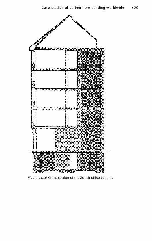
The CarboDur strengthening system was utilised on one side of the wall forthree storeys (Fig. 11.15) using 100mm wide strips, 1.2mm in thicknesslaid diagonally across the wall (Fig. 11.16). The practical advantage of usingthe CarboDur laminates was lightness of the material. One long length oflaminate was used, therefore, eliminating the need for lap joints. In additionthe crossover detail was very simple.
The existing render was removed from the wall and the surface was gritblasted in the areas to be bonded to achieve an open textured profile. Localprotuberances were removed mechanically. Prior to the application of theadhesive, the surfaces were vacuum cleaned to remove dust.
The CarboDur laminates were anchored in the adjacent new reinforcedconcrete column. In order to achieve optimal adhesion between the carbonfibre laminate and the grouting mortar, the anchorage zone of the laminateswas slightly curved and provided with a special bonding bridge. In additionto this, steel ties were placed across the laminates and fixed into the con-crete with an epoxy resin. All anchorage zones were then grouted with acompatible epoxy mortar.
To ensure the highest quality of work, specialist contractors were usedtogether with the following on site quality assurance programme:
• continuous visual over-all inspection by a supervising engineer,• adhesion tests on the prepared surfaces,• dewpoint control of the substrates prior to bonding and grouting,• sampling of all epoxy batches, as used and mixed on the site, to measure
compressive strength and flexural modulus,• recording of all delivery documents, including production numbers and
expiry dates.
11.3.3.2.3 Conclusion
With this strengthening, the lateral resistance and the ductility of the inte-rior URM fire wall could be increased many times over at reasonable costs.It took no more than four days to carry out all the strengthening work. Thiswas the first ever project where carbon fibre laminates had been used tostrengthen a masonry wall (Fig. 11.17).
SOR11 12/19/98, 4:25 PM302
Case studies of carbon fibre bonding worldwide 303
Figure 11.15 Cross-section of the Zurich office building.
SOR11 12/19/98, 4:25 PM303

304 Strengthening of reinforced concrete structures
Figure 11.16 Application of the CarboDur plates to the masonry wall.
304
Figure 11.17 URM fire wall strengthened with CarboDur carbon fibrestrengthening system.
SOR11 12/19/98, 4:25 PM304

Case studies of carbon fibre bonding worldwide 305
11.3.4 Strengthening of historic wooden bridge,Switzerland
11.3.4.1 The problem
11.3.4.1.1 Historical background
In 1807 a covered wooden bridge near Sins in Switzerland was designedand constructed to allow horse drawn vehicles to cross over the river(Fig. 11.18). The original supporting structure design consisted of archesstrengthened by suspended truss members. On the western side of thebridge this construction can still be seen and is currently in good condition.
During the Civil War in 1847 because the bridge was identified as astrategic crossing point, the eastern side was partially destroyed. In 1852,this section of the bridge was rebuilt with a modified supporting structuremade up from a combination of suspended truss members with interlockingtensioning transoms. The present permitted vehicle load carrying capacityof the bridge is 20 tonnes.
During its life the bridge has been rehabilitated in different ways. Themost recent investigation which consisted of a load test identified thatthe wooden pavement and several cross beams were incapable of carryingthe current vehicle loading requirements.
Figure 11.18 General view of wooden bridge, Sins, Switzerland.
SOR11 12/19/98, 4:26 PM305

306 Strengthening of reinforced concrete structures
11.3.4.2 The solution
11.3.4.2.1 Strengthening details
In 1992, strengthening work commenced on the bridge and the originalwooden pavement was replaced with 20cm thick transversely prestressedbonded wooden planks. The most highly loaded cross beams were streng-thened using carbon fibre plates bonded to the external surfaces. Each crossbeam was constructed from two oak beams placed upon each other sepa-rated by wooden blocks to increase the depth (Fig. 11.19). The dimensionsof the upper beam were 300 mm by 300mm and of the lower beam 370mmdeep by 300mm wide.
To achieve the required bonding surface, the beams had to be prepared.The most suitable method of preparation for this project was achieved byusing a portable planing system (Fig. 11.20). The cross beams were streng-thened with 1.0mm thick plates at widths of 250mm at the upper leveland 200 mm at the lower level (Fig. 11.21). Once the preparation wascarried out and dust removed, the plates were bonded to the beams(Fig. 11.22).
Figure 11.19 Cross-section of the historic bridge near Sins. Selectedcross beams were strengthened with carbon fibre plates.
SOR11 12/19/98, 4:26 PM306

Case studies of carbon fibre bonding worldwide 307
Figure 11.20 Portable system to plane the surface of the woodencross beams.
Figure 11.21 View of strengthened cross beams.
SOR11 12/19/98, 4:26 PM307

308 Strengthening of reinforced concrete structures
Figure 11.22 A close-up of the bonded plate to the underside of thebeam.
Figure 11.23 The use of bonded gauge studs to monitor long termperformance.
SOR11 12/19/98, 4:26 PM308

Case studies of carbon fibre bonding worldwide 309
The Swiss Federal Laboratories for Material Testing and Research(EMPA) used pulse infrared thermography to assess the in situ suitability ofthe bonding operation. The use of strain gauges and gauge studs to monitorthe long term performance of the strengthening technique is currently beingused on selected cross beams (Fig. 11.23).
11.3.4.2.2 Conclusion
The success of this project has given confidence and practical experience inthis method for poststrengthening timber structures. For the future preser-vation of historic bridges and similar structures, this poststrengtheningtechnique offers many advantages over traditional strengthening methods.Because carbon fibre plates are thin, strong and flexible, they can be de-signed and installed to provide a cost effective solution which does notdetract visually from the original design of the structure.
11.3.5 Strengthening subways, Tyne and Wear, UK
11.3.5.1 The problem
Following an assessment of the structure by South Tyneside MBC it wasnecessary to upgrade the flexural loading capacity of subways to accommo-date 40 tonne vehicle loadings.
Figure 11.24 Applying CarboDur laminate to underside of underpass,Tyne and Wear.
SOR11 12/19/98, 4:26 PM309

310 Strengthening of reinforced concrete structures
Figure 11.25 View of completed bonding operation, subways, Tyneand Wear.
11.3.5.2 The solution
To increase the flexural capacity, 100mm wide, 1.2mm thick carbon fibrelaminates were bonded to the roof of the subway. The CarboDur laminatesand adjacent concrete roof were overlaid with 15.0mm of prebagged poly-mer modified Gunite and coated with a high performance protective con-crete coating. The total length was 130m (Figs. 11.24 and 11.25).
11.3.6 Underpass at Great Missenden,Buckinghamshire, UK
11.3.6.1 The problem
The underpass was understrength to sustain current loading requirementsof 40 tonnes.
11.3.6.2 Solution
Cracks in the soffit of the deck were first injected with an epoxy resin. Minorconcrete repairs were also carried out prior to bonding the 100mm wide,1.2mm thick CarboDur laminates. The total length was 172m (Figs. 11.26and 11.27).
SOR11 12/19/98, 4:26 PM310

Case studies of carbon fibre bonding worldwide 311
Figure 11.26 General view of the underpass, Great Missenden.
Figure 11.27 Completed bonding operation of underpass, GreatMissenden.
SOR11 12/19/98, 4:26 PM311

312 Strengthening of reinforced concrete structures
11.3.7 Strengthening of loggia slabs (balconies),Magdeburg, Olvenstedt, Germany
11.3.7.1 The problem
All the slabs in a multistorey block of flats were sagging due to fatigue andinsufficient reinforcement. This reduced the safe use of the balconies. Toenable levelling of the upper surface and to compensate for the new deadload and existing live loads, the balconies needed strengthening.
11.3.7.2 The solution
The underside of the loggia slabs was strengthened with three 50mmwide, 1.2mm thick carbon fibre laminates. The total length was 1140m(Figs. 11.28 and 11.29).
Figure 11.28 View showing block of flats, Magdeburg.
SOR11 12/19/98, 4:26 PM312
Case studies of carbon fibre bonding worldwide 313
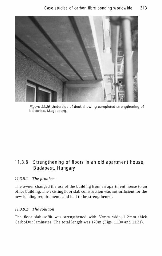
Figure 11.29 Underside of deck showing completed strengthening ofbalconies, Magdeburg.
11.3.8 Strengthening of floors in an old apartment house,Budapest, Hungary
11.3.8.1 The problem
The owner changed the use of the building from an apartment house to anoffice building. The existing floor slab construction was not sufficient for thenew loading requirements and had to be strengthened.
11.3.8.2 The solution
The floor slab soffit was strengthened with 50mm wide, 1.2mm thickCarboDur laminates. The total length was 170 m (Figs. 11.30 and 11.31).
SOR11 12/19/98, 4:26 PM313

314 Strengthening of reinforced concrete structures
Figure 11.30 Apartment house, Budapest.
Figure 11.31 Application of CarboDur laminates.
SOR11 12/19/98, 4:26 PM314
Case studies of carbon fibre bonding worldwide 315
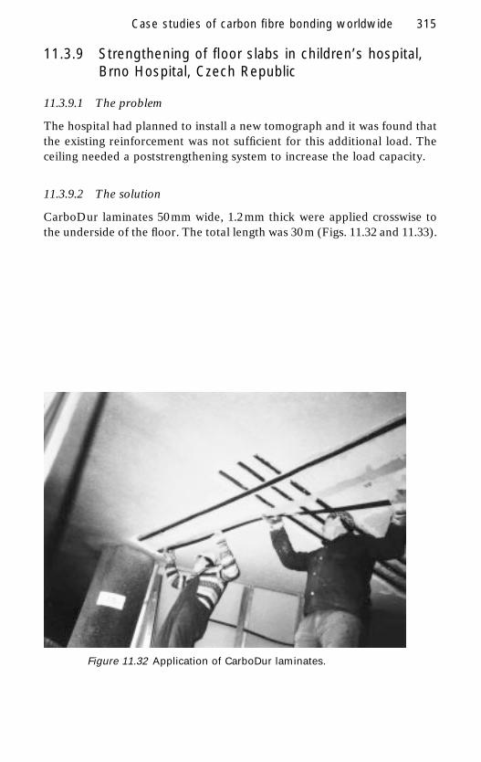
11.3.9 Strengthening of floor slabs in children’s hospital,Brno Hospital, Czech Republic
11.3.9.1 The problem
The hospital had planned to install a new tomograph and it was found thatthe existing reinforcement was not sufficient for this additional load. Theceiling needed a poststrengthening system to increase the load capacity.
11.3.9.2 The solution
CarboDur laminates 50 mm wide, 1.2 mm thick were applied crosswise tothe underside of the floor. The total length was 30m (Figs. 11.32 and 11.33).
Figure 11.32 Application of CarboDur laminates.
SOR11 12/19/98, 4:26 PM315

316 Strengthening of reinforced concrete structures
Figure 11.33 Completed installation.
11.3.10 Floor strengthening of town hall, Auckland, NewZealand
11.3.10.1 The problem
During the course of the construction work on the town hall it was foundthat the two mezzanine floors in the main entrance area did not havesufficient reinforcement to comply with current codes. The engineersneeded to design a poststrengthening system that could be installed toincrease the live load capacity of the existing floors (Fig. 11.34).
11.3.10.2 The solution
The floor slab soffits were strengthened with 50mm, 1.2 mm thickCarboDur laminates installed at 600mm intervals. The total length was200m (Fig. 11.35).
SOR11 12/19/98, 4:26 PM316

Case studies of carbon fibre bonding worldwide 317
Figure 11.35 View showing plates bonded to structural floor slabsubstrate.
317
Figure 11.34 General view of town hall, Auckland.
SOR11 12/19/98, 4:27 PM317

318 Strengthening of reinforced concrete structures
11.3.11 Strengthening of apartment balconies due to highdeflections: multistorey flats in Loano, Genova,Italy
11.3.11.1 The problem
The cantilever balconies on a multistorey block of flats had an end deflec-tion in excess of 12mm, together with associated cracks in the concrete. Thebalcony slabs had been underdesigned and required strengthening.
11.3.11.2 The solution
Poststrengthening of the balconies was carried out using four plates, 50mmwide, 1.2mm thick and 1.2 m in length on the upper surface of the slab andbeam. A load test was carried out and the deflection was reduced to 2.0mm(Fig. 11.36).
Figure 11.36 Load testing of balcony at Loano.
SOR11 12/19/98, 4:27 PM318

Case studies of carbon fibre bonding worldwide 319
11.3.12 Strengthening of a concrete waffle slab, Stuttgart,Germany
11.3.12.1 The problem
To upgrade the college complex another floor was to be added to thebuilding. To bear the additional load, the original roof slab had to bestrengthened to comply with the new floor loadings.
11.3.12.2 The solution
The slab was strengthened with 500 m of 80mm wide, 1.2 mm thick lami-nates and 250 m of 50mm wide, 1.2 m thick laminates. The thin section ofthe plates allowed the simple detailing of crossovers at the intersections ofthe beams (Figs. 11.37 and 11.38).
Figure 11.37 Offering CarboDur laminates up to the roof beams,Stuttgart.
SOR11 12/19/98, 4:27 PM319

320 Strengthening of reinforced concrete structures
Figure 11.38 The completed project with simple crossover detailsshown, Stuttgart.
11.3.13 Strengthening of longitudinal concrete bridgebeams, Niederwartha near Dresden, Germany
11.3.13.1 The problem
The whole concrete road bridge had to be repaired due to fatigue andenvironmental influences. An assessment of the bridge found that thelongitudinal beams required strengthening to increase the live load capacity(Fig. 11.39).
11.3.13.2 The solution
The beams were strengthened on the underside with a total of 250m, 80mmwide, 1.2mm thick CarboDur laminates and 250m of 50 mm wide, 1.2mmthick CarboDur laminates (Fig. 11.40).
SOR11 12/19/98, 4:27 PM320

Case studies of carbon fibre bonding worldwide 321
Figure 11.40 View of post-strengthened beam.
321
Figure 11.39 General view of repair work, concrete bridge,Niederwarthar near Dresden.
SOR11 12/19/98, 4:27 PM321

322 Strengthening of reinforced concrete structures
11.3.14 Horgen ferry bridge, Switzerland
11.3.14.1 The problem
A deficit of lateral reinforcement in the top deck of this reinforced concretebridge necessitated a strengthening programme. The lack of reinforcementand resultant moment diagram is shown in Fig. 11.41. The shaded area ofthe diagram shows the reduced moment 4.0m from the edge of the bridgeparapet.
11.3.14.2 The solution
To overcome this loading problem, strengthening of the deck transverselywas carried out in 1997 from the top surface using over 700m of CarboDurlaminates (Fig. 11.42). The thickness of the CFRP plates resulted in mini-mum alteration to the structure.
Figure 11.41 Moment diagram for Horgen ferry bridge: lateralmoment, solid line; movement of resistance of steel reinforcement,dashed line; moment deficit, shaded area.
SOR11 12/19/98, 4:27 PM322

Case studies of carbon fibre bonding worldwide 323
11.3.15 Devonshire Place bridge, Skipton, UK
11.3.15.1 The problem
Mouchel was appointed by North Yorkshire County Council to repairDevonshire Place bridge in Skipton, North Yorkshire. The bridge has aprecast prestressed concrete hollow section edge beam. A number of thetendons in the edge beam were damaged during an inspection, weakeningthe edge of the bridge in flexure.
11.3.15.2 The solution
Using knowledge gained from the extensive work done on ROBUST,a single sheet of CarboDur laminate plate was bonded to the undersideof the bridge to replace the lost flexural capacity. The traditional approachof bonding steel plates was clearly not suitable for this bridge due toaccess restrictions. In addition, the existing concrete was not thick enoughto support anchor bolts which would have been required if steel plateswere used. The CarboDur laminate was bonded to the bridge with Sikadur30 adhesive. The plate bonding required no bolts or scaffolding andthe bridge remained open during the process which was completed withinone day.
2400 mm 3200 mm
2000 mm
6000 mm
1300
mm
CarboDur CFRP Strip
Iv Iv
Figure 11.42 Lateral poststrengthening of the deck with a total of700m of CarboDur CFRP strips.
SOR11 12/19/98, 4:27 PM323

324 Strengthening of reinforced concrete structures
11.3.16 Nestlé chocolate factory, Tutbury, UK
11.3.16.1 The problem
Mouchel was commissioned by Nestlé to inspect and access the capacity ofa number of main beams supporting a factory floor in Tutbury to cater fora 30% increase in floor loading due to the installation of new plant andprocessing equipment. The brief also stipulated that there was to be mini-mal disruption to the factory operations.
11.3.16.2 The solution
Mouchel designed the strengthening scheme utilising the CarboDur lami-nate plate. In total 11 beams were required to have their flexural capacityincreased by 30% to cater for the extra loading. This was achieved bybonding one strip of CarboDur laminate plate, 120mm wide by 1.2 mmthick, centrally along the soffit of each of the beams. Around 100m ofCFRP plate was required for the entire operation. No scaffolding equip-ment was required, due to the lightness of the CarboDur plates, whichmeant minimum disruption to the factory operations and short contractduration. Sikadur 30 adhesive was used to bond the plates to the soffits ofthe beams. The carbon fibre composite bonding operation was completed inless than two days.
11.4 References
Farmer N (1997) ‘Strengthening with CFRP laminates’, Construct Repair II(7) 2–4.Midwinter K N (1997) ‘Plate bonding carbon fibre and steel plates’, Construct
Repair II(7) 5–9.Meier U (1995) ‘Strengthening of structures using carbon fibre/epoxy composites’,
Construct Building Mater 9(6) 341–351.Schwegler G (1994) ‘Masonry construction strengthened with fibre composites
in seismically endangered zones’, 10th European Conference on EarthquakeEngineering, Vienna.
Shaw M (1997) ‘Structural strengthening with external plate bonding’, InternationalConference on Building Envelope Systems & Technology, Bath, UK, April 1997.
Walser R and Steiner W (1997) ‘Strengthening of the Rhine bridge Oberriet-Meiningen’, Proc. Recent Advances in Bridge Engineering – Advanced rehabilita-tion, durable materials, non-destructive evaluation and management, ed. U Meierand R Betti, July 1997, pp 127–133.
SOR11 12/19/98, 4:27 PM324