1.1 the rich - na62.web.cern.ch · pdf filethe last straw chamber and the lkr calorimeter is...
TRANSCRIPT

1.1 The RICH
1
1.1 The RICH
A detector is needed to fulfill the following tasks:
• Separate π+ from µ+ between 15 and 35 GeV/c momentum providing a muon suppression
factor of at least 10−2
• Measure the pion crossing time with a resolution of about 100 ps or better;
;
• Produce the L0 trigger for a charged track.
A Ring Imaging Cherenkov (RICH) detector is the natural candidate for particle identification. The first requirement leads to the choice of Neon gas at about atmospheric pressure as the Cherenkov radiating medium; a reasonable compromise between the number of produced photoelectrons (1) (roughly linear with the length of the radiating medium) and the available space in the NA62 layout between the last straw chamber and the LKR calorimeter is achieved with a gas container not longer than 18 m in the beam direction. The second requirement leads to the choice of fast single anode photomultipliers, while the first one would point to PM as small as possible and packed as close as possible. A brief explanation of the choices is given in the following.
When a particle of velocity (in units of speed of light c) crosses a medium with index of refraction , it emits a radiation at an angle with respect to the particle trajectory such that:
forming a Cherenkov cone of half angle . The threshold velocity , below which no radiation is
emitted, is given by yielding , while the maximum angle of emission is
reached for .
The momentum threshold for a particle of mass to emit Cherenkov radiation is:
In order to have full efficiency for a 15 GeV/c momentum pion, the threshold should be about 20%
smaller or 12.5 GeV/c, corresponding to (n−1)=62×10−6 which corresponds almost exactly to Neon at atmospheric pressure. In a RICH detector, the Cherenkov cone is reflected by a spherical mirror, placed at the downstream end of the radiating volume, onto the mirror focal plane (which is located at the upstream end of the gas container). The cone image is a ring of radius
Where is the mirror focal length.

NA62 TD Document
2
The number of emitted photons through a radiator thickness per unit of photon energy is predicted by the Franck-Tamm equation as a function of the Cherenkov angle (assuming a charged particle of unit charge):
The actual number of photoelectrons (i.e. electron produced by photons impinging on the PM
photocathode) is a convolution of the previous equation, the spectral response of the PM, the reflectivity of the mirror, the transparency of the gas and of any medium in front of the PM, the geometrical acceptance of the PM, multiplied by the radiator length L, i.e. the mirror focal length. Each of these quantity depends on the photon energy. Even if the index of refraction depends on it, it is traditional to summarize the performances of a RICH through a quality factor N0:
where a good detector can have N0 around 100 cm−1. If the probability to produce more than one photoelectron in the same PM is not negligible (as in our case) what is really meaningful is the number of fired PM Nhit which will be smaller than Np.e..
1.1.1 Expected Performances The RICH performance expectations have been validated testing a full length prototype with particle beams. These results are described in section 1.1.6.
1.1.2 The Vessel The RICH vessel must contain the Neon gas without leak and will be operated in slight overpressure w.r.t. the external atmosphere. The gas density must remain constant (within 1%) over long time. The PM will be located at the upstream end of the vessel: together with their support structure they must be outside the fiducial acceptance of the apparatus, bringing the diameter of the vessel to 3.8 m.
Figure 1 Schematic drawing of the RICH detector; the downstream section of the vessel is cut to show the mirrors and the beam pipe.
1.1.2.1 The Vessel Functional Requirements (FR) FR.1. Develop a rational installation strategy with in-situ part assembly and alignment possibilities for this large size vessel.
FR.2. Provide a tight, clean and non-reflective containment to the radiator gas. Provide a stiff gas containment, keeping in mind possible pressure variations, between 0 and 150mbar overpressure.

1.1 The RICH
3
FR.3. Provide an interface to the two photomultiplier arrays at the upstream end near 3 and 9 o'clock, keeping in mind gas and light tightness and space requests for services and access.
FR.4. Hold the mirror support panel at the downstream end; provide possibilities for fine-adjustment.
FR.5. Support a beam pipe.
FR.6. Provide minimal-material budget, in the form of "entrance window" and "exit window" respectively, of the frontal surfaces at the upstream and downstream vessel ends. The minimal-material outer diameters are dictated by criteria of downstream photon acceptance. Furthermore, minimal material near the beam axis is especially important.
FR.7. Provide as rational as possible an interface between the decay vacuum volume (the downstream end of which is materialized as STRAW 4, see chapter 3.1) and the radiator gas volume.
FR.8. Incorporate strategic flexibility, such that the important investment in hardware could be re-used with ease in a possible, second-generation Experiment with neutral, undeflected beam.
Figure 2 Main parameters of the integration of the rotated vessel in NA62; section along y=0 plane.
1.1.2.2 Proposed Solution From the combination of FR.5 , FR.6 and FR.7 , it is logical to aim at a vessel design with centered beam pipe, and to rotate the entire vessel (by 2 mrad) with embedded beam pipe about a vertical axis, such that it be aligned along the deflected, secondary NA62 beam (see Figure 3).
Then, it follows that the minimal-material requirement extends up to r = 1.1 m at the entrance, and 1.4 m at the exit1
It can be argued that the vessel does not have to be as high as that. Such remark would hint at making a vessel of e.g. race-track shape, resulting in a smaller radiator gas volume. However, at these scales, it
. The two photomultiplier arrays count up for a diameter of about 0.7 m each. Adding up necessary overhead such as flanges, it results in a vessel about 4.2 m wide at the entrance.
1 Due to the photon geometrical coverage of LAV11 and LAV12, respectively.

NA62 TD Document
4
is mandatory to aim at constructions providing stiffness by traction2
. This argument drives the following shaping of the vessel parts:
Figure 3 The RICH upstream end is offset in +X direction by 36mm to accommodate the deviated beam inside the vacuum tube. This lateral displacement with respect to STRAW4 is compensated by an eccentric interface ring (in red). The downstream end of the RICH is centered on the experimental axis, so that the whole vessel is in fact rotated by 2mrad.
- circular, rather than elliptical or race-track, outer cylinder. Outer diameter >4m at entrance;
- windows as membranes rather than bending-stiff panels ;
- bridging of the diameter gap between entrance window and outer cylinder: conical sheet rather than thick, flat plate perpendicular to axis. Protrude the cone by appropriate, short cylinders to receive the flanges of the photomultiplier array.
Technological difficulties with non-circular flanges are another argument in favour of a circular concept.
2 For a load of pressure type, deflections scale with the fourth power of the relevant linear dimension in case the stiffening comes from bending, and with the second power in case of traction.

1.1 The RICH
5
The windows would be sheets welded in inner and outer flanges, all in aluminum alloy 50833
Figure 4
. The welded assembly would be hydro-formed, to give the membrane sheet the optimal shape, and at the same time induce the optimal strain hardening in the sheet material (see ). Although detailed dimensioning has yet to be done, it is believed that the sheets would be 4 and 3mm thick, for entrance and exit window respectively.
All other components would be in ferro-pearlitic structural steels like S235 or S355. Indeed, there do not seem to exist (non-)magnetic requirements on equipment, so far downstream of the NA62 spectrometer magnet. The integrity and cleanliness of the inner surfaces would be achieved by an epoxy painting. One could think of either a two-component, room-temperature cure system, or, if possible for our dimensions, a well-known "epoxy coating", being a spraying of a mono-component epoxy powder, sticking by electrostatic forces, then cured in an oven. One should select a process resulting in a "mat", non-reflective surface. The steel sheet thickness will be driven by technological issues, and is believed to range between 5 and 10mm4
The cylindrical container shall be made in several parts, to be bolted together in-situ. The parts can be of gradually somewhat diminishing diameter. The diameter of the last part is driven by the size of the mirror support panel
.
5
The total cylinder length is about 17m, driven by the mirror focal length.
. Intermediate parts shall not hinder the reflected light. The concept of interface between adjacent cylindrical vessel parts is a copy of that of the vacuum and helium tanks of NA31/NA48. It allows small adjustments in rotation about all three principal axes, prior to compressing the O-ring seal.
There is a cast-in-concrete bottle neck of passage at the downside of the main shaft to the ECN3 cavern, being about 3.87 m wide. Thus, we have set a limit of 3.83 m on the dimension of each vessel part. Parts of greater diameter have to be kept below limit length, and vice-versa, long parts shall not exceed the limit diameter. We have four parts in the current design6
The remaining main steel part in the vessel assembly is the "cone" in front. Even though short in z, it has the greatest diameter of all parts, and is quite complicated.
.
Upstream of the entrance window, there is an intermediate vessel piece bridging the gap to STRAW 4 (see Figure 3 and Figure 4). The RICH entrance window is thus the unique separator between the decay vacuum volume and the RICH radiator gas volume. The intermediate piece would also be in structural steel, and is a vacuum vessel. The entrance window has to stand up to 1.15 bar. The rest of the vessel, including exit window, has to stand up to 0.15 bar. A special interface ring will allow the intermediate
3 4.5% Mg, 1% Mn, mass fractions.
4 Indeed, 1mm or even less would already be sufficient to stand the pressure.
5 Currently, the support panel rather than the minimal-material aperture requirement, drive the outer diameter of the exit window.
6 It turns out that ECN3 passage, rather than transport, sets the stricter requirement.

NA62 TD Document
6
vessel piece to be connected to STRAW 4. For the initial Experiment with charged beam, this ring will have to be machined with eccentricity, in order to cope with the transverse offset of the RICH, about 43 mm. For a future neutral beam run, a new, concentric, ring would be the only necessary piece of new equipment.
Figure 4 Upstream extremity of the RICH showing the PMT flange and the aluminum beam window (section along y=0 plane). The beam pipe diameter near the upstream end of the RICH has been
designed to be Ø ≥ 170 mm in order to prevent any material in front of the SAC photon acceptance.
In order to minimize material, especially at the upstream side, the beam pipe "starts" at the inner flange of the entrance window, with a minimal-engineering connection, thus simply flanged. Longitudinal decoupling is sought far downstream, in front of the LKR cryostat. Consequently, the beam pipe assembly in the RICH and even further downstream, is allowed to move, in z, according to any displacement of the entrance window. Inside the vessel, pipe weight will be supported, and transverse movement blocked, by thin wires. The exit window is decoupled from the vacuum system. The beam pipe continues through the window's inner hole. The window is connected to the beam pipe with a special bellows, providing radiator gas tightness. The window could be taken off from the vessel without disturbing the vacuum (see Figure 5).

1.1 The RICH
7
Figure 5 Main parameters of the vessel near the downstream end; section along y=0 plane.
1.1.3 The Gas System There are five important requirements that need to be met by a suitable radiator gas for the NA62 RICH detector.
• Appropriate refractive index at atmospheric pressure
• Good light transparency in the visible and near UV
• Low chromatic dispersion
• Low atomic weight to minimize radiation length
• Non-flammable
Looking at the above criteria it is relatively straightforward to identify Neon as the most appropriate choice. Besides its suitable refractive index, Neon has a small chromatic dispersion combined with a low atomic mass. The RICH operating range starts at wavelength > 190nm which makes its performance quite insensitive to impurities in the gas. For example, the light absorption for trace pollutants of Oxygen and H2
O become noticeable only at wavelength below 190 nm. However, residual gases affect also the refractive index, which deteriorates the Cherenkov angle resolution, if their concentrations vary in time.

NA62 TD Document
8
CO2
Figure 6 is used as transition gas during the filling and emptying of the radiator and residual quantitative
could therefore be present in the gas. shows the light transparency of CO2 for an average light path length of 25.5m and different CO2 concentrations. The plot indicates that for low CO2 concentrations the transparency is near 100% down to wavelength of 195 nm. Test beam measurements confirm that the signal loss due to a residual CO2
concentration of 1% is smaller than 0.3%.
Figure 6 Relative light transparency in residual CO2 gas for a light path length of 25.5 m, for 0.1% (red), 1% (blue) and 10% of CO2
A number of relevant detector and gas system parameters are summarized in
(green) (2).
Table 1.
Table 1 Relevant detector and gas system parameter.
RICH radiator volume ≈ 200 m3 Operating gas 100% Ne
Residual trace gas concentrations: CO2 O2 H2O N2
< 0.1% < 0.1% < 0.1% < 0.5 %
Operating pressure Between 990 and 1010mbar (absolute)
Max. over/under pressure (rel. to atmosphere) + 150 mbar
- 0 mbar
Pressure regulation accuracy ± 1 mbar Flushing and purging flow rates 3 to 10 m3/h Gas density stability < 1% Detector leak rate < 1.0 * 10-2 Std. cc/s
0.75
0.8
0.85
0.9
0.95
1
175 180 185 190 195 200 205 210 215 220

1.1 The RICH
9
1.1.3.1 Outline of the Gas Modules The Rich gas radiator is a cylindrical vessel with an overall volume of 200m3. For mechanical reasons the gas pressure needs to be kept above atmospheric pressure with a maximum overpressure of 150 mbar.
To reduce design overheads and optimize long-term maintenance cost the gas system is build-up of functional modules (Table 2), which are technically very similar to the ones used in the LHC experiments.
Table 2 Gas system modules and their locations.
Module Situated in
Neon Supplies Gas Building B920
Distribution Module Experimental Area ECN3
Circulation and Pump Module
Build. 883 CO2
Buffer Volume (size 1 m
Absorber Module 3
Purifier (optional)
)
Circulation Module
PC4003
Pressure Control
PI
Buffer
~1’000 litre
2-3bar
PT
YV 6x23/1
6x24 PI6x24
To exhaust150 mbar
PSV
6x4
2
Flushing Gases
6181PI
PCV6x61
Hv6x62/1 6x61
HV 6x41
PT
ZC6x21
PC6x21
YV 6127/2
6126
100 mbar
PSV
61X
X
PT6xYZ
Purge
PT6x04
TT
Run
YV 6127/1
Exhaust
CO AbsorberModule
2O and H OPurifier2 2
Optional
Hv6x62/2
Air
CO2
ECN3
B 883
Exhaust
Neon or Co2 Inlet
GasAnalysis
GasAnalysis
GasAnalysis
GasAnalysis
GasAnalysis
FICV 6121
HV 6127
Openif P < 0 mbar
orP > 150 mbar
PSHL
Figure 7 Schematic layout of the RICH gas system (blue = RICH radiator volume). The upper part shows the distribution located in the experimental hall. The lower part shows schematically the modules situated in B883.

NA62 TD Document
10
A schematic drawing of the gas system is shown in Figure 7. The large volume combined with a relatively expensive gas (135 CHF/m3) requires special precautions for a cost effective filling of the detector. As the vessel is unable withstand vacuum, the radiator volume is first filled with carbon-dioxide to replace air. The gas is then circulated in closed loop, and the Neon is introduced while absorbing the CO2 in a molecular sieve filter.
All remote valves, instruments and sensors (pressure, temperatures and flows) are read-out by a programmable control computer (PLC) allowing remote filling or emptying of the detector.
In the following a short technical description of the modules is given.
1.1.3.1.1 The Distribution Module (DM) The DM is located in the experimental cavern near the detector itself; a schematic layout of the module is shown in the upper part of Figure 7. Two gas inlets and two gas outlets, one of each at the bottom and on top of the detector, connect the distribution rack to the radiator, thus the higher density CO2 gas can be filled from the bottom and the lower density Neon from the top. The inlet flow is metered using a variable area flow meter; pressure transmitters measure the pressures at the inlet, inside the radiator and at the outlet.
All four gas lines have pneumatic shut-off valves, so that the detector can be hermetically isolated from the system. The DM contains a passive and pneumatically driven pressure protection, which open the radiator volume to atmosphere if the pressure exceed the mechanically allowed limits ( 0 < Pvessel < 150 mbar).
From the DM the radiator can be purged manually with CO2 or air in single pass mode.
1.1.3.1.2 The Circulation Module (CM) When running in closed loop mode the outlet gas from the radiator must be compressed for return to the surface and re-cycling through the CO2 absorber. Using a dry membrane compressor the gas is compressed by about 0.5 to 1.0 bar.
The CM is shown in Figure 8. The return gas from the radiator is entering the circulation module and the pressure at this point is regulated by means of a remotely controlled bypass valve around the compressor.

1.1 The RICH
11
PV 4003 PCV 4018
ZC4003
4017
Pump 4101
PI
1234
PT PIPT PI
PC4003
4004PSH
4004
HV 4115HV 4002
4006
Pump 4201HV 4215HV 4210
optional
4006 4006NV 4112
NV 4212
/1 /2/1
from pressuresensor
PCV 4021
PSL4023 4021
PI
Supply N7 bar
2
GF 4020
Vac.pump
HV
4113
HV
4112
HV
421
3
HV
421
2
HV
4010 HV
401
8HV
4014YV 4040NV 4019HV 4110
HV 4030
YV 4001 HV 4041
option 2option 1
option 3
HV
4009
HV
4008
HV 4007
Figure 8 Component layout of the pump or Circulation Module.
1.1.3.1.3 The CO2 Absorber Module (AM) The motivation for the CO2 AM is a cost effective filling of the large radiator volume in closed loop circulation with a minimal loss of Neon (see section 1.1.3.2).
The AM (Figure 290) consists of two absorption cartridges of identical size (24 litre volume), which are installed in parallel. One of the cartridges is in operation while the second one can be regenerated. To allow a fast and efficient regeneration the cartridges are equipped with heating jackets (+180oC) and active cooling.
Each cylinder contains approximately 15 kg Molecular Sieve 13X, and can absorb up to 3.5 Nm3 of CO2 gas. After saturation with CO2 the cartridges can be regenerated by either:
• lowering the pressure to a few mbar (absolute) at room temperature, or by
• lowering the pressure and heating up to 180o
The first method is very fast (regeneration time between 10 and 20 min.), but yields a lower absorption capacity. The second method combines low pressure and high temperature prolonging the cycle time to approximately 5 hours, but it provides a higher absorption capacity and an outlet purities of a few ppm residual CO2 concentration.
C
To absorb 200 m3 of CO2 between 100 and 150 cycles are required if both methods are used. In the beginning the returned CO2 concentrations is near 100% and one cartridge will saturate in 10 to 20 minutes. As the CO2 concentration in the loop diminishes the saturation time of the cartridges prolongs gradually. When the CO2 fraction reaches a few %, the 2nd regeneration method can be used, to reduce the residual CO2 fraction after the absorber module to less than 5 ppm.
The CO2 concentrations in the gas are monitored at the inlet and outlet of the module.

NA62 TD Document
12
1.1.3.2 Filling and Emptying of the Detector Before introducing the Neon, the entire system (gas system and radiator) is filled with clean CO2 to remove air from the system. When the residual air in the radiator is at the required level the inlet flow is switched to Neon. As soon as the Neon fraction in the radiator outlet flux exceeds a few % the system is changed to closed loop circulation and the CO2 absorber is switched on. The circulation flow rates can range from 3 and 10 m3/h, so that in the beginning the capacity of one absorber cartridge will be used up quickly, and if high flow rates are used the absorption may be interrupted by the regeneration cycles of the CO2 absorber. The Neon input flow is regulated by the pressure in the system and will, therefore, automatically match the quantity of CO2 absorbed. When the residual CO2 concentration in the radiator is at the required level, the circulation flow can be stopped, and the radiator pressure is ramped up (or down) to the desired value.
To empty the Neon, the vessel can be purged in single pass mode with CO2 or Air.
1.1.3.3 Running of the Detector The neon density influences the refractive index n following the relation
Figure 9 Schematic layout of the CO2 Absorber Module.

1.1 The RICH
13
where is neon refractive index at NTP (1.000067), is the neon density at NTP ( 0.9001 kg/m3), and the density at operating conditions (≈ 0.814 kg/m3 for T= 25oC and P= 1 bar).
Since the detector performance is rather immune to impurities one can envisage operating the detector with a sealed gas volume without continuous gas renewal. This concept is advantageous because temperature variations will in this case not influence the gas density.
At the beginning of a physics run the radiator pressure will be set accurately to the desired operation pressure, e.g. 1000 mbar (absolute). The gas density is then left constant by closing all valves to the radiator volume.
To guaranty sufficient stability for long physics runs the leak rate of the detector should be smaller than 1.0 * 10-2 Std. cc/s. In case the leak tightness or the gas purity requirements cannot be met it is possible to upgrade the system with a density feed-back loop and a purifier module, so that the gas system can be operated in closed loop with in-line purification. In this case the radiator pressure can be regulated such that the gas density remains unchanged following the average Temperature of the vessel:
is the universal gas constant ( 8.314472 J/K mol) and the atomic mass of Neon (20.179 gr/mol).
1.1.4 The Mirrors A mosaic of spherical mirrors is used to image the Cherenkov cone into a ring on its focal plane. To avoid absorption of reflected light on the beam pipe the mirrors are divided into two spherical surfaces: one with the centre of curvature to the left and one to the right of the beam pipe. The total reflective surface exceeds 6 m2, so that it is practical to use a matrix of 20 mirrors (see Figure 12 and Figure 13).
1.1.4.1 Mirror Layout and Quality The RICH detector uses spherical mirrors with a nominal curvature radius of 34m and hence a focal length of 17m. Twenty mirrors will be needed, 18 of hexagonal shape (35 cm side) and two of semi-hexagonal shape (see Figure 10 and Figure 11). The two latter ones are used in the centre and have a circular opening to accommodate the beam pipe. The mirrors are made from 25mm thick glass substrate coated with aluminium. A thin dielectric film is added for protection and to improve the reflectivity.
There are three main optical parameters that must be met by each mirror:
• A D0 not larger than 4 mm (the D0
• A radius of curvature within ±20 cm from the nominal one.
is the minimum diameter of a circle which collects 95% of the light of a point–like source placed in the curvature centre)
• In the wavelength range between 195 and 650 nm the average reflectivity should be better than 90%.

NA62 TD Document
14
Figure 10 Dimensions of an hexagonal mirror. The positions of the two holes to support the mirror are indicated.
Figure 11 Dimensions of a semi-hexagonal mirror. The positions of the two holes to support the mirror are indicated.

1.1 The RICH
15
1.1.4.2 The Mirror Supports
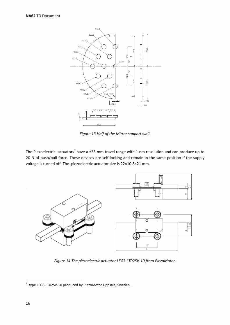
The mirror support structure has to sustain a total weight of approximately 400 kg and must guarantee long-term stability of the mirror positions. On the other hand it is important not to add too much material to minimize photo-nuclear reactions which can deteriorate the veto capabilities of the subsequent detectors. In that context, a 10 cm thick carbon-fiber or aluminium honeycomb structure has been chosen as mirror support structure (see Figure 13).
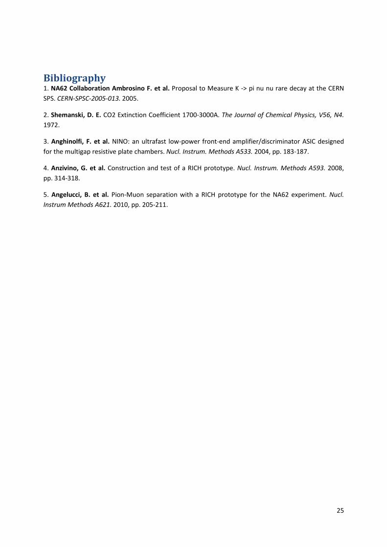
Each mirror must be supported and adjustable for alignment. Two holes, 12 mm wide, will be drilled on the not-reflecting surface of the mirror leaving the barycentre in the middle of them, with an inter-distance of 540 mm for the hexagonal mirrors and of 70 mm for the semi-hexagonal ones. A dowel with a spherical head will be inserted on each mirror hole and will be used to sustain the mirror. Piezo-electric actuators(see Figure 14) will allow a remotely controlled orientation of each hexagonal mirror. The two half-hexagonal mirrors in the center are fix.
Figure 12 The mirrors layout with the detail of the support for one mirror.
NA62 TD Document
16
Figure 13 Half of the Mirror support wall.
The Piezoelectric actuators7
have a ±35 mm travel range with 1 nm resolution and can produce up to 20 N of push/pull force. These devices are self-locking and remain in the same position if the supply voltage is turned off. The piezoelectric actuator size is 22×10.8×21 mm.
Figure 14 The piezoelectric actuator LEGS-LT02SV-10 from PiezoMotor.
7 type LEGS-LT02SV-10 produced by PiezoMotor Uppsala, Sweden.

1.1 The RICH
17
1.1.4.3 The Mirror Alignment The mirror alignment will be routinely checked during data taking selecting particles whose Cherenkov rings are completely contained in a single mirror and with a track angle measured by the magnetic spectrometer. However, the first time and perhaps later during the periodical shut-down a laser alignment will be done. The laser alignment starts with one mirror that will be chosen as reference. A laser beam, originating in the focal plane, will be directed to that mirror and oriented so that the reflected beam impinges on a selected point in the focal plane. The laser beam will be translated, parallel to itself, to a neighbour mirror by means of two high quality retro-reflectors: this mirror can then be aligned in such a way that the reflected laser beam impinges on the same point as for the reference mirror. The laser beam needs to be adjusted close to the borders of each mirror, because an accurate translation can be done only over a few centimetres. This procedure will be iterated to cover all the mirrors. Two reference mirrors will be chosen, one for the mirrors pointing to the left and one for those pointing to the right of the beam pipe. The laser beam will be prepared as parallel as possible using a telescopic optical device.
1.1.5 The Photon Detection System The granularity of the photon detection is an essential parameter to optimize the angular resolution of the detector. On the other hand the number of photo detectors has large impact on the cost of the RICH apparatus. A reasonable compromise between the number of sensors, the photon acceptance and the sensor dimensions must be found. According to the experiment simulation, a total of 2000 photomultipliers is sufficient to match the detector requirement. This arrangement leads 1000 PMT’s on each side and to a photo-sensor pitch of 18mm.
1.1.5.1 The Photomultipliers (PMT) Several photomultiplier options have been investigated and the best compromise between fast response, small dimensions and cost seems to be the Hamamatsu R7400 series (see Table 3). These metal cover single anode photomultipliers exist in several versions and three of them have been tested in the laboratory and in the beam.
• The U-04 was considered for its spectral response ranging from the red to close UV but was discarded because of its low efficiency compared to other versions.
• The U-06 version has a quartz entrance window which allows to be sensitive up to 165 nm.
• TheU-03 model has a UV glass entrance window which cuts the sensitivity at 185 nm.
Due to other factors (mirror reflectivity, neon transparency, separation windows in the vessel, etc.) no major difference has been seen between the two latter types of PMT’s in a test beam held in 2007, therefore the cheaper U-03 has been selected. In Table 3 the main properties of the PM (at 800 V) are summarized.
Figure 15 and Figure 16 show the dimensions and the spectral sensitivity of the R7400U-03 PMT . The selected PMT’s have a minimum gain of 5×10⁵ at 800 V; the first delivered 328 PMT’s have an average gain of (8±2)×105 at 800 V.

NA62 TD Document
18
Table 3 Main characteristics of Hamamatsu R7400U-03 photomultiplier at 800 V
PM R7400U-03 Type Head on; Metal
PackageTube for UV-visible range
Size 16 mm Active diameter 8 mm Min λ 185 nm Max λ 650 nm Peak sensitivity 420 nm Cathode Radiant Sensitivity 62 mA/W Window UV glass Cathode Type Bialkali Cathode Luminous Sensitivity 70 mA/lm Anode Luminous Sensitivity 50 A/lm Gain 7.0×10⁵ Dark current after 30 min. 0.2 nA Rise Time 0.78 ns Transit Time 5.4 ns Transit Time Spread 0.28 ns Number of Dynodes 8 Applied Voltage 800 V
Figure 15 Dimensions of the Hamamatsu R7400U-03 photomultiplier: side view (left), rear view (right).
The 8 dynode voltages are provided by a Hamamatsu E5780 HV divider (2.8 MΩ total resistance) with cylindrical shape with 17.0±0.2 mm diameter and 15.0÷0.5 mm length. It has three connectors: a RG-174/U cable for signal output and two AWG22 cables for the high (negative) voltage supply and for grounding.

1.1 The RICH
19
Figure 16 Spectral sensitivity for different Hamamatsu R7400 photomultipliers.
The PMT time response is of great importance for the RICH and has been investigated in detail. The Transit Time Spread given by the supplier is expressed in FWHM because the response has important tails and is far from a Gaussian shape. Several systematic contributions have been identified in the time distribution:
• a small peak before the main peak, attributed to the electron extraction from the first dynode instead from the photocathode;
• a second small peak about 1.2 ns after the main peak is attributed to electrons extracted from the photocathode, after reflection from the first dynode towards the cathode and coming back to the same dynode.
1.1.5.2 The PMT Power Supply The PMTs need 800-1000 V negative voltage (we assume 900 V in the following) supplied with low noise. To reduce cost, four PMTs are supplied by a single HV channel, so that about 500 HV channels are needed. CAEN 12 or 24-channels HV boards8 fulfil the requirements and they can be inserted in appropriate standard CAEN crates9
8 CAEN 12-channels A1733N or 24-channels A1535S boards
. The HV system will be remotely controlled by the DCS system. The 12-channel s A1733N board has a maximum of 4(3) kV output voltage (dual range) with 2(3) mA
9 CAEN SY1527 (16 slots) or SY2527 (6 slot)

NA62 TD Document
20
maximum output current. The voltage and current resolutions are 250 mV and 200 nA, respectively; the voltage ripple is smaller than 30 mV pp. The 24-channels A1535S has a maximum 3.5 kV output voltage, with 500 mV resolution, and 3 mA output current, with 500 nA resolution; the typical voltage ripple is smaller than 20 mV pp; all HV channels have a common floating return.
1.1.5.3 The Frontend Electronics The PMT output signal has a roughly triangular shape with the same rise time as the PMT (0.78 ns on average) and a fall time about twice the rise time. At 900 V PMT supply voltage (average gain of 1.5×10⁶) the output charge is about 240 fC corresponding to a peak current of 200 µA and to a negative peak voltage of 10 mV over 50 Ω. There is also a large variation in gain performances among the PMT’s. In order to profit of the fast PMT response, the 8-channel NINO ASIC (3) was chosen as discriminator. This chip has an intrinsic resolution of 50 ps and was developed for the output signal of multigap resistive plate chambers. To match the optimal NINO performance region, the PMT output is sent to a current amplifier with differential output: a 32-channel customized printed circuit will be used for this purpose, sending the output to a board containing 4 NINO ASIC. The NINO chip is operated in time-over-threshold mode and its LVDS output signal is sent to 512-channels TELL1 boards equipped with HPTDC chips with 97.7 ps LSB producing 19 bits long words (corresponding to a maximum of 51 µs). Both the leading and trailing edge of the LVDS signal are recorded providing information on the original signal width, used for the time slewing correction in the analysis.
Figure 17 View of one of the flanges with 1000 PMT’s. The cooling system is shown.

1.1 The RICH
21
1.1.5.4 The PMT Support To simplify the access to the photomultipliers the PMT’s are mounted outside the radiator gas volume. This PMT assembly consists of two independent flanges: a radiator flange with quartz windows and an independent aluminium flange holding the PMT’s. A schematic cross-section of the arrangement is shown in Figure 19. The aluminium flange holding the PMT’s is shown in Figure 18. The radiator flange is shown in Figure 17.
The light exit holes on the radiator flange are covered with a highly reflective aluminized Polyethylenterephthalat (trade name Mylar) foil and they have the shape of a truncated circular parabolic (also called “Winston Cone” ) to tunnel the light through the window aperture. On the outside of each hole (the PM side) a 1 mm deep, 14 mm wide cylindrical hole allows to position and glue the quartz window (a 0.5 mm deep, 2 mm thick groove accommodates the glue).
Figure 18 One of the aluminum flanges which holds the PMT's.

NA62 TD Document
22
Figure 19 View of one of the two stainless steel flanges which separate the Neon gas from the PMTs.
Figure 20 Detail of the PM support structure: the upper part (purple) is the aluminum flange holding the PMTs with the O-ring ( black); the bottom part(red) is the flange of the radiator volume with the
quartz window in blue.

1.1 The RICH
23
The PMT’s are mounted on the external aluminium flange in front of the quartz windows. They are isolated from environment light and water cooled. A cylindrical hole, 16.5 mm wide and 10 mm high will be drilled in the aluminium flange for each PM, followed by a 17.5 mm wide and 22 mm high hole for the HV divider. A 1 mm thick O-ring (with 17.5 mm outer and 13.5 mm inner diameter) will be placed in front of the PMT (kept in place by a 2 mm thick gorge in the hole placed 0.5 mm above the end ) and pressed against the quartz window to avoid external light to reach the PMT. A 5±1 mm thick O-ring (with the same outer and inner diameter of the 1-mm O-ring) will be placed on the back of the PMT (after the end of the HV divider) to close the hole and avoid external light; this O-ring also guarantees a good thermal contact between the PMT and the aluminium flange and absorbs the tolerance in the PMT total length .
1.1.5.5 The Cooling System The PMT HV divider will dissipate about 0.3 W per tube or 300 W per side (1000 PM) and a cooling system is required to avoid a local heat source on the radiator. A water cooling pipe (ф=10mm copper) situated inside an aluminium rod in between the PMT rows is used to remove the heat. An industrial chiller10
unit is used to cool and pump the water .
1.1.6 Prototype Test Beam Results A RICH prototype was built to demonstrate the feasibility of the RICH project. In 2007 the prototype vessel was installed in the ECN3 cavern and commissioned. The radiator was cylindrical, 17 m long and 60 cm diameter, filled with Neon gas at atmospheric pressure. A spherical mirror with 17 m focal length was used with PMT’s placed in the mirror focal plane.
1.1.6.1 The 2007 Prototype Test Beam In fall 2007 the RICH prototype was equipped with 96 PMT’s of different types and exposed to a 200 GeV/c momentum negative pions beam derived from the CERN SPS. An event time resolution of 65 ps was measured with an average number of 17 hits per event; the Cherenkov angle resolution turned
out to be 50 µrad with some bias induced by the limited number of PMT’s used in this test. Both Hamamatsu R7400U-03 and U-06 PM were tested and the latter type showed a 30% broader time resolution than the first one without a major improvement in light collection efficiency (the U-06 has a quartz entrance window). This result drove the choice of the U-03 type for the final detector.
The results of the 2007 prototype test beam have been published in (4).
1.1.6.2 The 2009 Prototype Test Beam In spring 2009 the RICH prototype was equipped with 414 PMT’s of Hamamatsu R7400U-03 type to
validate the π−µ separation. The prototype was exposed to a positive beam derived from the CERN SPS with adjustable beam momentum. Positrons had an average number of 19 hits per event; the time
resolution of the previous test was confirmed. The π−µ separation between 15 and 35 GeV/c was
measured at various momenta and the µ suppression factor was estimated to be 1% integrated in the range of interst. In a first part of the test the same mirror as in 2007 was used, while in a second part a
10 For example Fryka Kältetechnik DLK402 between -10 and +40 C at a maximum power of 380 W.

NA62 TD Document
24
new mirror was installed; both mirrors have been manufactured by the same supplier, but the former was aluminized and coated with MgF2 by the supplier while the latter was aluminized and coated with SiO2 and HfO2 at CERN in an attempt to improve the total mirror reflectivity. No major difference between the two mirrors was observed in the data.
The results of the 2009 prototype test beam have been published in (5).
25
Bibliography 1. NA62 Collaboration Ambrosino F. et al. Proposal to Measure K -> pi nu nu rare decay at the CERN SPS. CERN-SPSC-2005-013. 2005.
2. Shemanski, D. E. CO2 Extinction Coefficient 1700-3000A. The Journal of Chemical Physics, V56, N4. 1972.
3. Anghinolfi, F. et al. NINO: an ultrafast low-power front-end amplifier/discriminator ASIC designed for the multigap resistive plate chambers. Nucl. Instrum. Methods A533. 2004, pp. 183-187.
4. Anzivino, G. et al. Construction and test of a RICH prototype. Nucl. Instrum. Methods A593. 2008, pp. 314-318.
5. Angelucci, B. et al. Pion-Muon separation with a RICH prototype for the NA62 experiment. Nucl. Instrum Methods A621. 2010, pp. 205-211.