1100r+ user manual
TRANSCRIPT

1100R+ User Manual

Table of Contents Setup ............................................................................................................ 1
Introduction ................................................................................................................................... 1 Cirris Customer Support ................................................................................................................ 1 You Should Have Received ........................................................................................................... 1 You May Have Received ............................................................................................................... 2 Tester Options ............................................................................................................................... 2 Setting up the Tester ..................................................................................................................... 3 Connecting a Printer ...................................................................................................................... 4 Attaching Scanner Add-ons ........................................................................................................... 5
Tester Basics .............................................................................................. 8
Basic Operation ............................................................................................................................. 8 Downloading Updates and Changing the Language ...................................................................... 8 Security ......................................................................................................................................... 8 Changing the Speaker Volume ...................................................................................................... 9 Adapters ...................................................................................................................................... 10 Installing Adapters ....................................................................................................................... 12 Duplicating the Adapter Setup ..................................................................................................... 14 Cable Signatures ......................................................................................................................... 15 Adapter Signatures ...................................................................................................................... 16 The Loaded Test Program and other Memory Locations ............................................................. 16
Using the Tester ........................................................................................ 17
Creating a Test Program ............................................................................................................. 17 Learning a Cable With No Connections ....................................................................................... 18 Learning a Single-Ended Cable ................................................................................................... 19 Documenting a Test Program ...................................................................................................... 20 Testing a Cable ........................................................................................................................... 21 Test Summaries .......................................................................................................................... 23 USB Thumb Drive ....................................................................................................................... 24 Managing Test Programs ............................................................................................................ 26 Importing Compressed Wirelists/Script Files ............................................................................... 29
Using CTLWIN ........................................................................................... 30
Common Uses for CTLWIN ......................................................................................................... 30 Running the CTLWIN Software ................................................................................................... 30 Editing Test Programs ................................................................................................................. 31 Help for CTLWIN ......................................................................................................................... 32
Preferences & Settings ............................................................................. 33
What are Preferences and Settings? ........................................................................................... 33 1100 R+ Factory Defaults ............................................................................................................ 34 Restoring Factory Default Preferences and Settings ................................................................... 34 What Happens When a Cable is Tested? .................................................................................... 34 User Preferences ........................................................................................................................ 35 Test Mode ................................................................................................................................... 36 External Switch............................................................................................................................ 36 Fault Location .............................................................................................................................. 37 Auto Start .................................................................................................................................... 37 Test Count ................................................................................................................................... 38
Auto Print .................................................................................................................................... 38 Digital Outputs ............................................................................................................................. 39 Factory Defaults .......................................................................................................................... 39 Volume ........................................................................................................................................ 39
Low Voltage Settings ................................................................................ 40
Learn and Test Parameter Settings ............................................................................................. 40 Connection Resistance ................................................................................................................ 42 LV Insulation Resistance ............................................................................................................ 43 Component Resistance ............................................................................................................... 44
Component Setting & Test ....................................................................... 45
Learn Components ...................................................................................................................... 45 Components Learned and Tested ............................................................................................... 45 Links ............................................................................................................................................ 46 4-Wire Kelvin ............................................................................................................................... 47
Cable Error Messages .............................................................................. 51
Low Voltage Errors ...................................................................................................................... 52 Component Errors ....................................................................................................................... 55
Digital I/O ................................................................................................... 56
Overview of Digital I/O ................................................................................................................. 56 Output Examples ......................................................................................................................... 59 Setting up the Events Outputs ..................................................................................................... 61
Tester Configuration ................................................................................. 62
1100 Upgrade Application ........................................................................................................... 62 1100 Utilities Application ............................................................................................................. 63 1100 File Compression Utility ...................................................................................................... 65 SPC Data Collection .................................................................................................................... 67 Changing Volume and Display Controls ...................................................................................... 69 Checking Version Information ...................................................................................................... 69
Software Installation Guide ...................................................................... 70
Requirements for a Station or Network Server............................................................................. 70 Installing easy-wire Software and Cirris Server Software ............................................................. 70 Starting the Software ................................................................................................................... 70 Updating the Server Configuration............................................................................................... 71 (1100) easy-wire PC Control for Benchtop Testers ...................................................................... 71 (CR, CH2) Attaching to a Network Database Server ................................................................... 71
General Information .................................................................................. 72
Calibration ................................................................................................................................... 72 Adapters and Fixturing ................................................................................................................ 72 Service ........................................................................................................................................ 72 Conditions for Operation .............................................................................................................. 72
Appendix ................................................................................................... 73
Specifications .............................................................................................................................. 73 Warranty...................................................................................................................................... 74

1
Setup
Setup
Introduction
This manual’s purpose is to help with the following:
Set up the tester Operate the tester Train new operators
The 1100R+ Quick Reference Guide is in the front pocket of this manual. Keep this document near the tester to help operators and technicians recall basic tester functions.
Cirris Customer Support
If you need assistance with your 1100R+ tester, a customer support representative is ready to assist you.
In the USA, call Cirris customer service toll-free at 1-800-441-9910. Outside the USA, enter the URL www.cirris.com/contact.html in your internet browser to find the Cirris Sales Office nearest you.
You Should Have Received
1100R+ Tester
Power Supply
CTLWIN Kit
Quick Reference Guide
Users Manual
Power Cord Plug type varies with country of receipt.
Probe
USB Thumb Drive

2
Setup
You May Have Received
Tester Options The 1100R+ tester can be equipped with additional options, such as networking and scripting capability. If you have already purchased either of these options, a sticker on the back of the tester identifies the option(s) you received. Each option is described below. To add either or both of these options to your 1100R+, call Cirris customer service at 1-800-441-9910. Networking Networking allows you to store test programs in a central location, easily collect test results, keep track of test programs, and make sure each tester on your production floor has access to the same test information. Additionally, you can easily back up test information to prevent it from being lost or deleted. Ultimately, operating multiple testers is more effective and time efficient with a network. SPC Data Collection SPC Data Collection allows you to store specific test data and retrieve that data for analysis. To enable SPC Data Collection, see 1100 Utilities Application on page 63. For more information, see SPC Data Collection on page 67. Scripting Scripting allows you adapt the tester’s behavior to fit your needs, extend applications by adding new features, and ease automation of tasks in the tester. Scripting can also be used to create and print custom labels for wire identification (see “Create Labels” in the Scripting manual). To enable scripting, see 1100 Utilities Application on page 63.
Adapters
Interchangeable adapter cards for connecting cables to the tester.
Scanner Add-ons Each Scanner Add-on provides 128 test points. Connect up to seven for a total of 1024 test points.
Networking Made Easy Kit Contains the Networking Made Easy CD and network setup instructions.

3
Setup
Setting up the Tester
1. Connect the power supply and
power cord together, then plug the tester into a grounded power outlet. The power supply can accept line voltages of either 120 VAC 60 hertz or 240 VAC 50 hertz.
2. Connect the probe to the tester.
3. On the back of the 1100R+
tester you will find two USB ports. If desired, insert the thumb drive into either port for access.
Note: Although not required, a thumb drive allows extra storage capacity and test program mobility. A thumb drive is required to set up a network. For more information, see USB Thumb Drive on page 24.
4. Turn on the tester and make sure
the main menu is displayed.
Note: If connecting either a printer or Scanner Add-ons, see the applicable sections that follow; otherwise, skip to Tester Basics on page 8.
These digits may be different, but the main screen should look similar to this.
SIGNATURE 1100R+ Set Preferences Set Up Test Program TEST: 1B4137-4Z020
Probe
Well grounded power is essential for the tester to operate accurately.
Power Supply
Power Cord
4
Setup
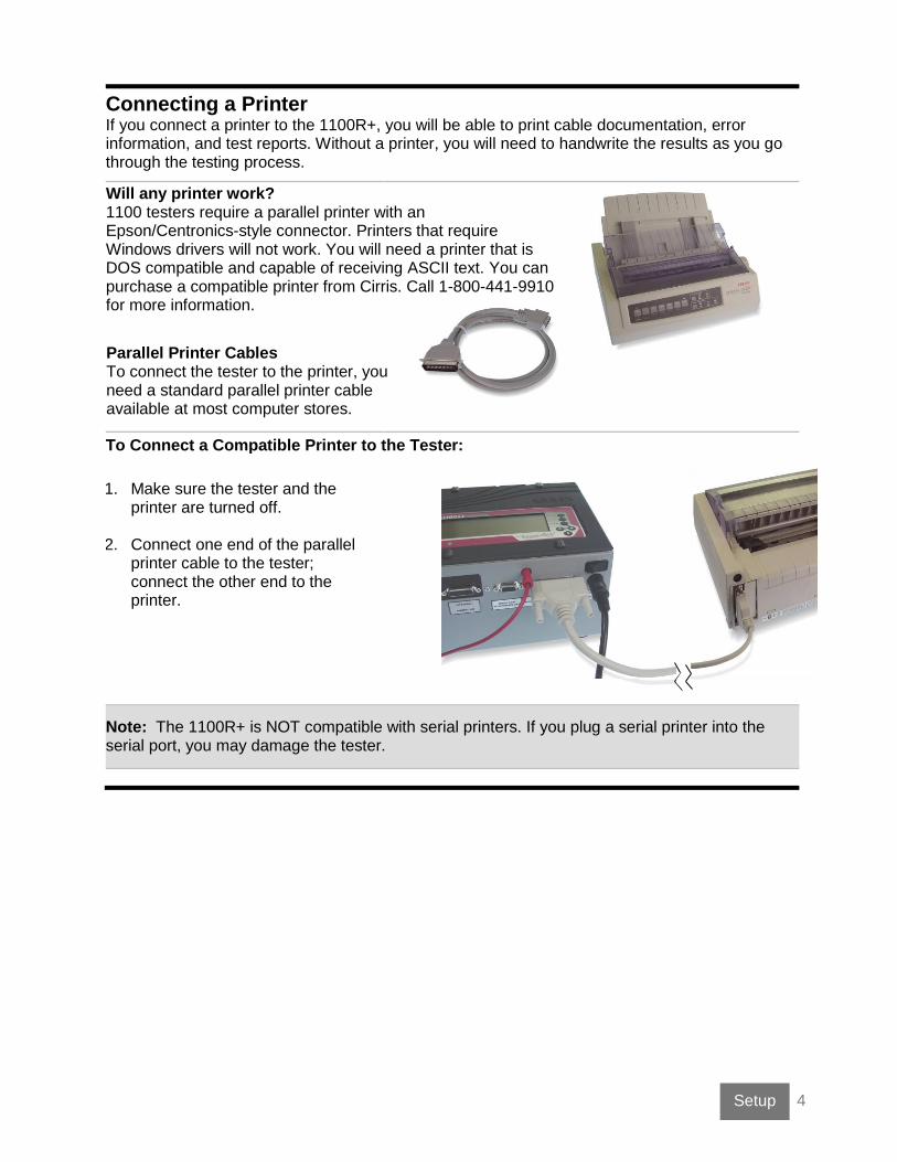
Connecting a Printer If you connect a printer to the 1100R+, you will be able to print cable documentation, error information, and test reports. Without a printer, you will need to handwrite the results as you go through the testing process.
To Connect a Compatible Printer to the Tester:
1. Make sure the tester and the
printer are turned off.
2. Connect one end of the parallel printer cable to the tester; connect the other end to the printer.
Note: The 1100R+ is NOT compatible with serial printers. If you plug a serial printer into the serial port, you may damage the tester.
Will any printer work? 1100 testers require a parallel printer with an Epson/Centronics-style connector. Printers that require Windows drivers will not work. You will need a printer that is DOS compatible and capable of receiving ASCII text. You can purchase a compatible printer from Cirris. Call 1-800-441-9910 for more information.
Parallel Printer Cables To connect the tester to the printer, you need a standard parallel printer cable available at most computer stores.

5
Setup
Attaching Scanner Add-ons Each Scanner Add-on provides an additional 128 test points. You can connect up to seven Scanner Add-ons to the 1100R+ tester for a total of 1024 points.
1. With the tester turned off, use a coin
or screwdriver to turn the fasteners on the removable J1-J2 cover plate to the horizontal position.
Note: The only time to remove the J1-J2 cover plate is when attaching a Scanner Add-on.
2. Turn the fasteners on the removable
J2-J4 cover plate to the horizontal position.
3. Remove both cover plates from the
tester.
4. Carefully remove the scanner assembly
and put it upside-down next to the tester.
Horizontal Position
J1-J2 Cover Plate
Horizontal Position
J3-J4 Cover Plate
Scanner Assembly

6
Setup
5. Remove the plastic cover piece on the
side of the tester.
6. Carefully place the scanner assembly back into the tester. Make sure the Add-on connector sticks out to the side of the tester.
7. Mate the Add-on connectors; make
sure they are fully connected.
8. Push the connectors into the main
unit.
To remove the plastic rivets holding the cover piece, use a
screwdriver or a hard flat object to push in the rivet, and then remove the rivet.
Cover Piece
Add-on Connector
Scanner Assembly
Scanner Add-on

7
Setup
9. Attach the Scanner Add-on to the
base tester using the side latches.
If connecting more than one Scanner Add-on, repeat the procedure attaching the next Add-on to the previous one.
10. Re-attach the cover plates.
11. Use a permanent marker to write the
adapter positions on each Add-on cover plate.
Note: Labeling the coverplates identifies adapter positions to help you understand tester prompts and error messages.
Side Latch
Continue this sequence on subsequent Add-ons.
Label the first Add-on coverplate:
J6 J8
J5 J7
Label the second Add-on coverplate:
J10 J12
J9 J11

8 Tester Basics
Tester Basics
Basic Operation
Downloading Updates and Changing the Language All 1100R+ testers come with the newest version of tester software when purchased; however, new software is released regularly. You can connect a computer to the tester using the serial port that comes with the CTLWIN kit, and use the 1100 Upgrade Application to update the tester software. This application can also be used to change the tester interface language if needed. English and Spanish are currently available; other languages may be available in the future. For more information, see “1100 Upgrade Application” on page 62.
Security When using your 1100R+, you may see a lock symbol next to a menu selection. This symbol indicates the selection cannot be changed. By connecting a computer to the tester, you can choose to lock or unlock certain menu selections. This capability might be used if, for example, you wanted to keep operators from creating new Test Programs or from changing the tester settings. For more information, see “1100 Utilities Application” on page 63.
Menu Lock Symbol
Menu Title
Always on top line in capital letters
Up/Down Buttons
Scroll menu options and setting
Selection Buttons
Select menu options
Available Directional Buttons
Displayed on top line, may include:
Top of list: more below
Scroll up or down
Scroll up or go back
Back Button
Returns to the previous or main menu
Good/Bad LEDs
Green if cable passes the test; Red if cable has errors
SIGNATURE 1100R+ Set Preferences Set Up Test Program TEST: 39E92F-4Z020
9 Tester Basics
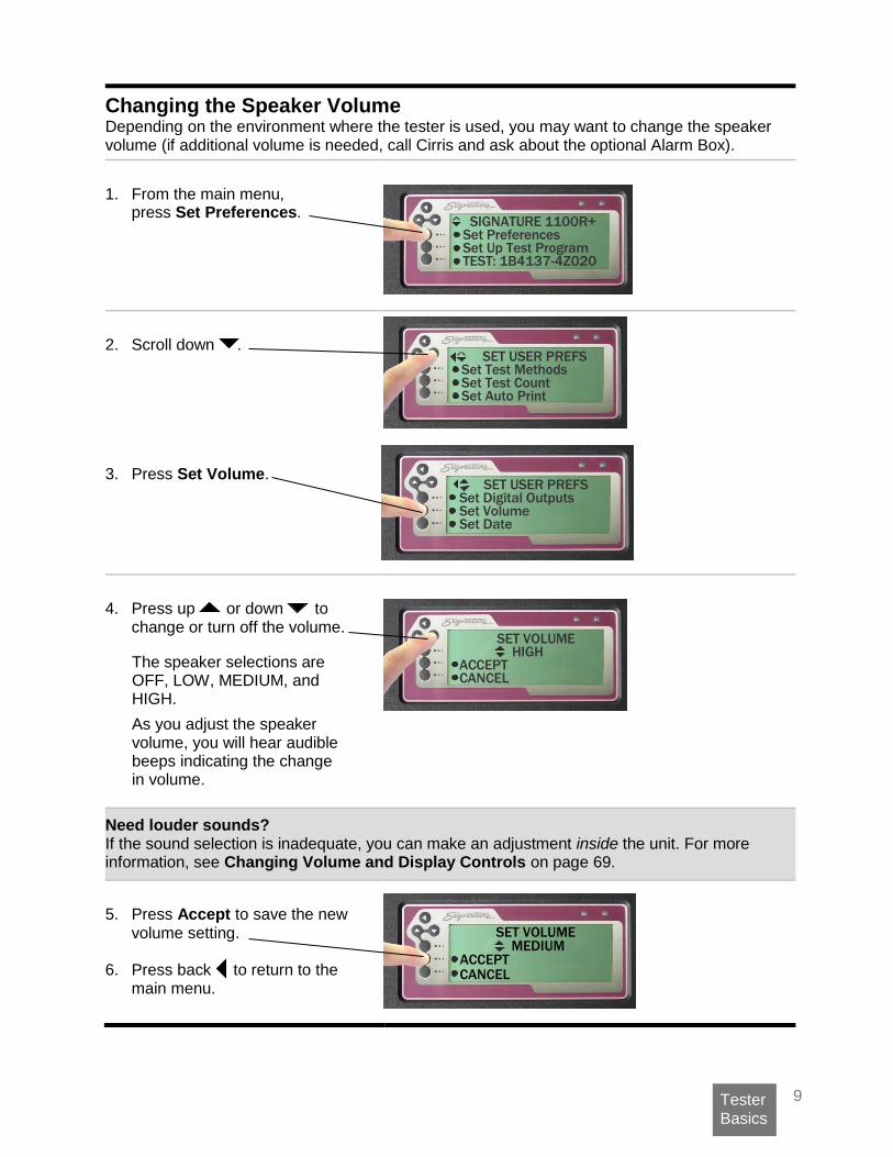
Changing the Speaker Volume Depending on the environment where the tester is used, you may want to change the speaker volume (if additional volume is needed, call Cirris and ask about the optional Alarm Box).
1. From the main menu,
press Set Preferences.
2. Scroll down .
3. Press Set Volume.
4. Press up or down to
change or turn off the volume.
Need louder sounds? If the sound selection is inadequate, you can make an adjustment inside the unit. For more information, see Changing Volume and Display Controls on page 69.
5. Press Accept to save the new
volume setting.
6. Press back to return to the main menu.
The speaker selections are OFF, LOW, MEDIUM, and HIGH.
As you adjust the speaker volume, you will hear audible beeps indicating the change in volume.
SET VOLUME
ACCEPT CANCEL
MEDIUM
SIGNATURE 1100R+ Set Preferences Set Up Test Program TEST: 1B4137-4Z020
SET USER PREFS Set Test Methods Set Test Count Set Auto Print
SET USER PREFS Set Digital Outputs Set Volume Set Date
SET VOLUME HIGH ACCEPT CANCEL
10 Tester Basics
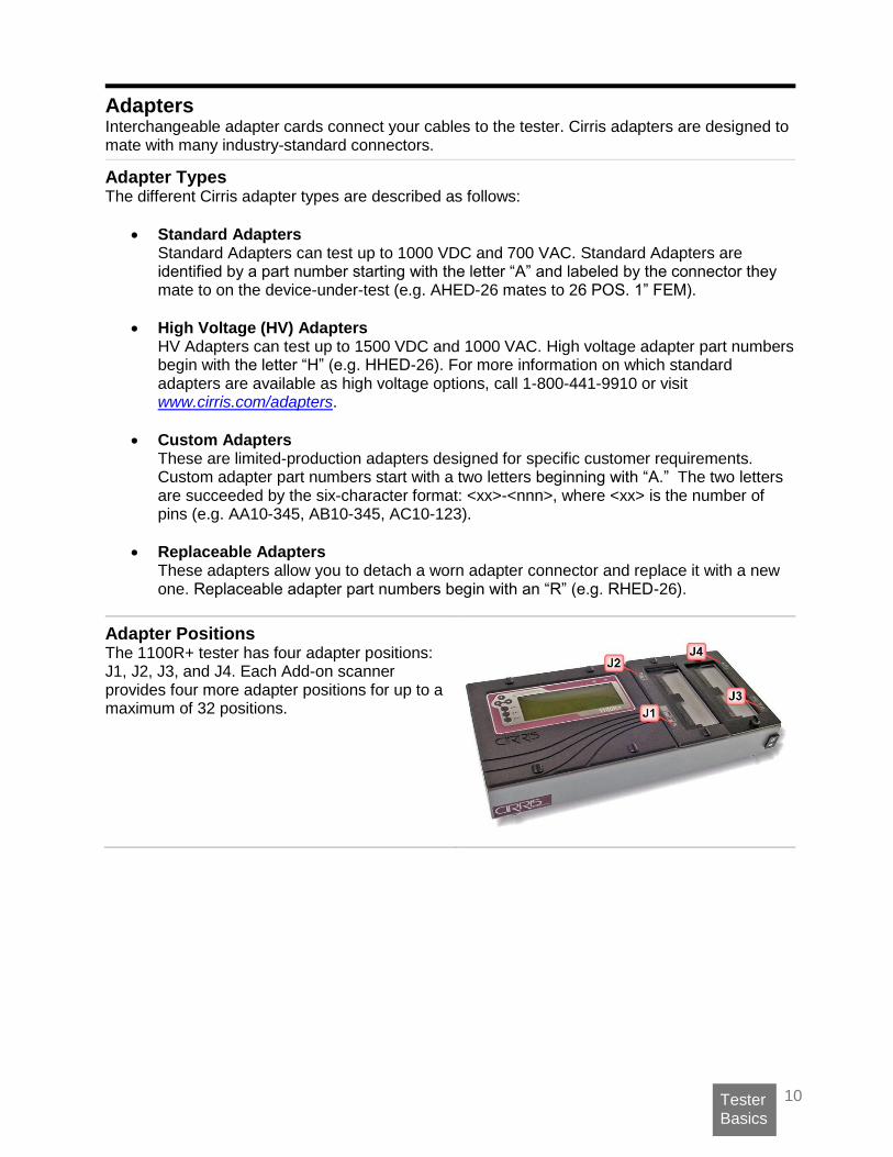
Adapters Interchangeable adapter cards connect your cables to the tester. Cirris adapters are designed to mate with many industry-standard connectors.
Adapter Types The different Cirris adapter types are described as follows:
• Standard Adapters Standard Adapters can test up to 1000 VDC and 700 VAC. Standard Adapters are identified by a part number starting with the letter “A” and labeled by the connector they mate to on the device-under-test (e.g. AHED-26 mates to 26 POS. 1” FEM).
• High Voltage (HV) Adapters HV Adapters can test up to 1500 VDC and 1000 VAC. High voltage adapter part numbers begin with the letter “H” (e.g. HHED-26). For more information on which standard adapters are available as high voltage options, call 1-800-441-9910 or visit www.cirris.com/adapters.
• Custom Adapters These are limited-production adapters designed for specific customer requirements. Custom adapter part numbers start with a two letters beginning with “A.” The two letters are succeeded by the six-character format: <xx>-<nnn>, where <xx> is the number of pins (e.g. AA10-345, AB10-345, AC10-123).
• Replaceable Adapters These adapters allow you to detach a worn adapter connector and replace it with a new one. Replaceable adapter part numbers begin with an “R” (e.g. RHED-26).
Adapter Positions The 1100R+ tester has four adapter positions: J1, J2, J3, and J4. Each Add-on scanner provides four more adapter positions for up to a maximum of 32 positions.

11 Tester Basics
Adapter Sizes
Cirris adapters come in three sizes: Single-High, Double-High, and Quad-High.
• Single-high Adapters Each single-high adapter supports up to 28 test points and consumes 32 test points. Single-high adapters can occupy any of the four “J” positions.
This image shows a single-high adapter in position J1 (positions J2, J3, and J4 are still available).
• Double-high Adapters Each double-high adapter supports up to 64 test points and consumes 64 test points. Double-high adapters can occupy the J1 and J3 positions.
This image shows a double-high Adapter in position J1 (positions J3 and J4 are still available).
• Quad-high Adapters Each quad-high adapter supports up to 120 test points and consumes 128 test points. Quad-high adapters can only occupy position J1. This image shows a quad-high adapter in the J1 position (no other positions available).
12 Tester Basics
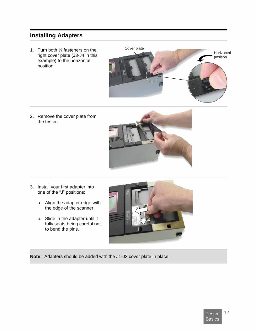
Installing Adapters
1. Turn both ¼ fasteners on the
right cover plate (J3-J4 in this example) to the horizontal position.
2. Remove the cover plate from
the tester.
3. Install your first adapter into
one of the “J” positions: a. Align the adapter edge with
the edge of the scanner.
b. Slide in the adapter until it fully seats being careful not to bend the pins.
Note: Adapters should be added with the J1-J2 cover plate in place.
Cover plate
Horizontal position
13 Tester Basics
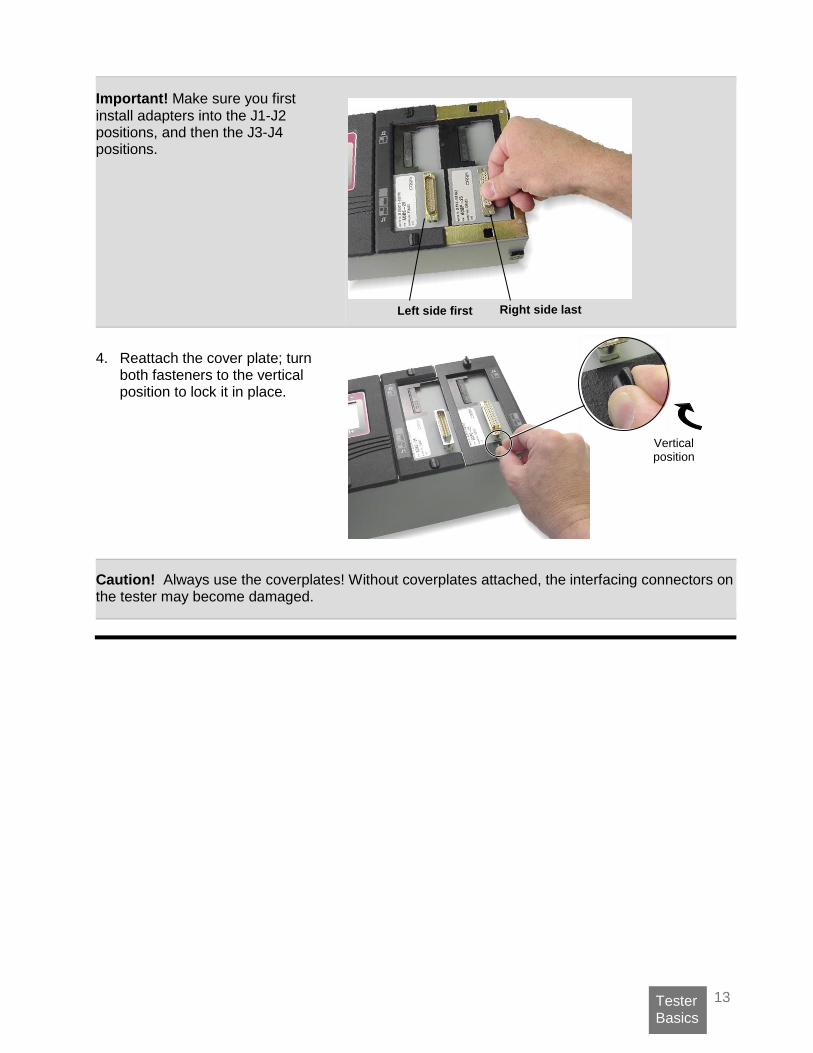
Important! Make sure you first install adapters into the J1-J2 positions, and then the J3-J4 positions.
4. Reattach the cover plate; turn
both fasteners to the vertical position to lock it in place.
Caution! Always use the coverplates! Without coverplates attached, the interfacing connectors on the tester may become damaged.
Vertical position
Left side first Right side last

14 Tester Basics
Duplicating the Adapter Setup Duplicating the adapter setup for a test is required in order to keep test results consistent. If you retrieve a test program from memory, you must install the adapters in the same positions defined when the test program was created.
When you begin a new test, the adapters can be placed in any available position.
When you recall the same test from memory, the adapters must be inserted in the original positions. Can’t remember where the adapters go? Don’t worry. If you saved the test program, the original positions will be displayed in the tester (see “Adapter Signatures” on page 16), or on the documentation used for the test.
Pins, Nets, and Net Lists
The word pin is generically used in this manual and in the tester interface to describe an individual contact or terminal in a connector.
An interconnection between two or more pins in a cable is called a net. When the tester learns a cable, it assigns each net in the cable a number.
All of the nets for a cable make up a net list. In some Cirris products, the term wire list is used interchangeably with the term net list.
RIGHT
WRONG
Matches the original setup.
Does not match the original setup.
Adapter positions in the original test setup.

15 Tester Basics
Cable Signatures
When learning a cable, the tester mathematically derives an 11-digit alphanumeric code for the cable called a Cable Signature. The cable signature helps you quickly identify a proper test setup.
The First Part of the Cable Signature.
The first part of the cable signature is called the Connection Signature, which helps identify a particular cable. The tester derives the connection signature from:
The wire pattern of the tested cable.
The adapters used.
The position where adapters are installed.
The Last Part of the Cable Signature.
The last part of the Cable Signature is called the Parameter Signature, which identifies Test Parameter Settings for the test.
Some examples:
The cable signature for each of these cables indicates they have identical connections, but different Test Parameter Settings.
These two cables are tested with the same Test Parameter Settings, but have different connections and connectors.
1B4137-4Z020
1B4137-4Z020
3F09EF–2J8NH
3F09EF–52AE3
3F09EF–2J8NH
54GF03–2J8NH
Note: If you changed
the name of a test program on your PC, that name will be displayed instead of the cable signature.
CABLE LEARNED Verify Test Save Test TEST: 1B4137-4Z020

16 Tester Basics
Adapter Signatures
Each adapter has an Adapter Signature. The tester uses the Adapter Signature to identify the adapter and ensure the test setup is correct.
You can view the required adapter signatures in the tester by doing one of the following:
• From the main menu, press “Set Up Test Program.” Then press “EDIT,” “View Other Settings,” and “View Adapters.”
• Start a test without an adapter and press “Show Required List.”
The Loaded Test Program and other Memory Locations
When you power up the 1100R+ tester, the cable signature or file name of the last loaded test is displayed on the main menu.
The last loaded test changes whenever you:
Learn a new cable
Retrieve a test from memory.
Internal Memory The C drive is the tester’s internal memory and the default drive. In addition to the last loaded test program, the C drive contains up to 99 memory locations where test programs can be stored.
For example, this screen shows test programs stored in memory locations 4, 5, and 6.
External memory A USB thumb drive is external memory, which expands your storage capacity. For more information, see USB Thumb Drive on page 24.
If you are using a thumb or network drive, the corresponding drive letter(s) will display on the screen.
REQUIRED ADAPTERS J1 F5B4E0 J2 03FAC1
SIGNATURE 1100R+ Set Preferences Set Up Test Program TEST: 1B4137-4Z020
The tester recognizes the Adapter Signature because of jumpers on the Adapter PC board. Adapter Signatures identify how many pins are in the adapter, where pin 1 is, and how the pins are numbered.
C: 4: A39CB4-2J8NH 5: 8E10C4-2J8NH 6: B34892-6F8N0
Saved test programs will be stored even if the tester is powered off.
C: <D:> <H:> 1: E3248D-2J8NH

17 Using the Tester
Using the Tester
Creating a Test Program A test program can be created by “learning” a sample cable. It is important to ensure the learned sample cable is a good cable. To create a test program from a sample cable:
1. Attach the sample cable:
Remove the J3-J4 cover plate.
Install the correct adapters.
Replace the cover plate.
Connect the sample cable.
2. Learn the sample cable:
From the main menu, press Set Up Test Program.
Press Create New Test.
Press LEARN.
3. Verify the sample cable:
If recreating a test previously verified: Make sure the new cable signature
or file name matches the previously verified test.
If this is the first time creating the test: Press Verify Test.
Scroll down .
Verify that the learned connections
match the build list of the cable exactly.
Double check the Test Parameter Settings.
Cover Plate Adapters
SIGNATURE 1100R+ Set Preferences Set Up Test Program TEST: 39E92F-4Z020
*If a printer is connected,
you can verify by printing. For more information, see Documenting a Test
Program on page 20.
1100H+ Cable Documentation
Cable Signature: 39E92F-4Z020J1 Adapter Signature: F5B4E0J2 Adapter Signature: 03FAC1
Connection Resistance: <Auto .5
CABLE LEARNED Verify Test Save Test Test: 39E92F-4Z020
CABLE LEARNED Verify Test Save Test Test: 39E92F-4Z020

18 Using the Tester
You’ve created a test program!
Press the back button to return to the CABLE LEARNED menu.
Remove the sample cable.
You are ready to:
• Save the learned test in memory.
• Start testing.
Learning a Cable With No Connections A test program can be created without connections by learning when no connections are present. This is useful when testing assemblies such as connectors or single-ended cables.
1. Install the correct adapters.
Remove the J3-J4 cover plate.
Install the correct adapters.
Replace the cover plate.
2. Learn the test setup.
From the main menu, press Set Up Test Program.
Press Create New Test.
Press LEARN.
3. Verify that there are no connections.
Press CONTINUE LEARN.
4. The test program is ready for use.
Save the learned test.
Start testing.
CABLE LEARNED Verify Test Save Test TEST: 39E92F-4Z020
At least one adapter must be installed to learn.
WARNING! No Connection(s) Found CONTINUE LEARN
CABLE LEARNED Verify Test Save Test TEST: 39E92F-4Z020
SIGNATURE 1100R+ Set Preferences Set Up Test Program TEST: 39E92F-4Z020

19 Using the Tester
Learning a Single-Ended Cable A test program can be created with a single-ended cable. This can help you ensure all the pins that should be wired are wired. Conversely, you can also discover if your single-ended cable has been wired to a pin that shouldn’t be wired.
1. Install the correct adapters.
Install the correct adapters.
Replace the cover plate.
Attach your single-ended cable.
2. Prepare the single-ended cable for a Learn.
From the main menu, press Set Up Test Program.
Press Create New Test.
Press Set Learn Settings.
Press Set Components.
Scroll down to SE Wires and SE Pins (to change the capacitance threshold, see #3 below).
3. Your cable’s threshold may change depending on its capacitance. The shorter/smaller the cable, the less capacitance there will be. To change the default threshold (in pF): Press SE Wires or SE Pins twice
(the first time will turn it off, the second time will take you to the SET SE_WIRES or SET SE_PINS screen).
Toggle the up and down arrows to increase or decrease the threshold.
At least one adapter must be installed to learn.
SIGNATURE 1100R+ Set Preferences Set Up Test Program TEST: 39E92F-4Z020
SET LRN COMPONENTS 4W Kelvin: OFF SE Wires: > 26.0 pF SE Pins: < 10.0 pF
SET LRN COMPONENTS 4W Kelvin: OFF SE Wires: > 26.0 pF SE Pins: < 10.0 pF
SET SE_WIRES > pF 26.0 pF ACCEPT CANCEL
20 Using the Tester
4. Scroll back to the CREATE NEW TEST screen and press Learn. It is normal to get a No Connection(s) Found warning message.
Press CONTINUE LEARN.
5. Learn background capacitance by removing the cable.
As prompted on the screen, remove your cable.
Press Continue.
Note: Everytime you test a batch of cables, you will be asked (once per batch) to remove the cable so that the tester may learn the background capacitance.
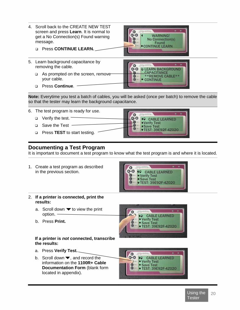
6. The test program is ready for use.
Verify the test.
Save the Test
Press TEST to start testing.
Documenting a Test Program It is important to document a test program to know what the test program is and where it is located.
1. Create a test program as described
in the previous section.
2. If a printer is connected, print the results:
a. Scroll down to view the print option.
b. Press Print.
If a printer is not connected, transcribe the results:
a. Press Verify Test.
b. Scroll down , and record the information on the 1100R+ Cable Documentation Form (blank form located in appendix).
WARNING! No Connection(s) Found CONTINUE LEARN
LEARN BACKGROUND CAPACITANCE **REMOVE CABLE** CONTINUE
CABLE LEARNED Verify Test Save Test TEST: 39E92F-4Z020
CABLE LEARNED Verify Test Save Test TEST: 39E92F-4Z020
CABLE LEARNED Verify Test Save Test TEST: 39E92F-4Z020
CABLE LEARNED Verify Test Save Test TEST: 39E92F-4Z020
21 Using the Tester
Testing a Cable
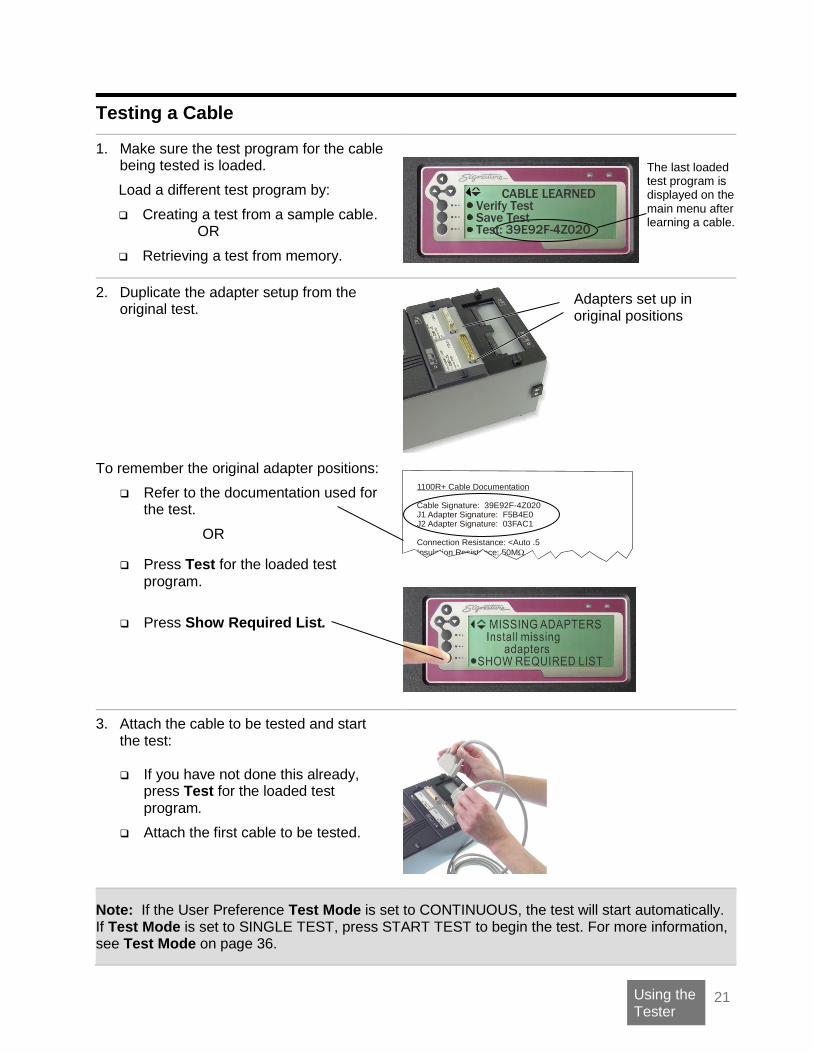
1. Make sure the test program for the cable being tested is loaded.
Load a different test program by:
Creating a test from a sample cable.
OR
Retrieving a test from memory.
2. Duplicate the adapter setup from the original test.
To remember the original adapter positions:
Refer to the documentation used for the test.
OR
Press Test for the loaded test program.
Press Show Required List.
1100R+ Cable Documentation
Cable Signature: 39E92F-4Z020J1 Adapter Signature: F5B4E0J2 Adapter Signature: 03FAC1
Connection Resistance: <Auto .5
Insulation Resistance: 50M
3. Attach the cable to be tested and start the test:
If you have not done this already,
press Test for the loaded test program.
Attach the first cable to be tested.
Note: If the User Preference Test Mode is set to CONTINUOUS, the test will start automatically. If Test Mode is set to SINGLE TEST, press START TEST to begin the test. For more information, see Test Mode on page 36.
Adapters set up in original positions
The last loaded test program is displayed on the main menu after learning a cable.
CABLE LEARNED Verify Test Save Test Test: 39E92F-4Z020

22 Using the Tester
The cable is tested. The tester performs a low voltage test on the cable. With factory default User Preferences, the tester repetitively performs the low voltage test on the cable searching for intermittent errors. The tester continues to do the intermittent test until the cable is removed or the test-run has ended.
If the cable passes:
The green LED will turn on.
The screen will display PASSED ALL TESTS.
If the Test Mode is set to
CONTINUOUS, the tester will automatically scan for intermittents and emit a tick tick tick sound.
Each tick signifies a good low voltage test of the cable.
If the cable fails:
The red LED will turn on.
The screen will display the type of error.
You can press View Errors or Print Errors to see the detailed error message.
The tester will sound an error tone,
based on the type of error.
Single Beeps = Open Two Beeps = Short Three Beeps = Miswire
4. Remove cable from the tester. When the cable is removed, the screen will prompt you to attach the next cable.
Note: If the screen does not display the ATTACH CABLE prompt after removing the tested cable, it means the tester still sees connections. Check your adapter or adapter cables for shorts.
For more information on error messages, see “Cable Error Messages” on page 51.
If the User Preference Test Mode is set to SINGLE, the tester will not perform the intermittent test.

23 Using the Tester
Test Summaries A test summary displays the results of a batch of tested cables.
To Display a Test Summary: 1. Test a good cable.
2. Scroll down . 3. Press Get Summary Count.
This screen shows the total number of tested cables, the number of bad tested cables, and the number of good tested cables. If you have a printer connected:
Press here to print the test summary.
The printed test summary shows the cable signature, parameter signature, cable serial number, parameter settings, adapter connections, and cable counts for a batch of tested cables. If desired, attach the printed test summary to a batch of tested cables to substantiate the test results of the batch.
Note: You can change the format of the Test Summary to display the count for good cables only. For more information, see Test Count on page 38.
Clearing or Resetting a Test Summary:
When you finish a run of cables and have the summary data you need, press STOP TEST RUN to complete the run. The summary counts (Total, Good, and Bad) will be reset to 0 in preparation for another run.
Probing the Pins The probe helps determine the pin count, identify flying leads, and locate cable errors. When you probe a point in a net, the tester initially displays up to six test points of the net. For large nets, you may have to scroll down to view all points of the net.
PASSED ALL TESTS
Remove Cable STOP TEST RUN START NEW TEST
PASSED ALL TESTS
Remove Cable STOP TEST RUN START NEW TEST
24 Using the Tester
USB Thumb Drive Cirris has supplied you with an external storage device, commonly referred to as a USB thumb drive. All 1100R+ testers released after August 1st, 2008 are equipped with USB ports. If your 1100R+ was released at an earlier date, contact your Cirris representative for upgrade information.
The thumb drive allows you to do the following:
Backup test programs.
Copy test programs between 1100 testers.
Copy test programs between the tester and a PC.
Custom File Names for Wirelists When you copy test programs to your PC via thumb drive, you can rename your wirelists with custom file names and then copy them back to the tester.
How file names function
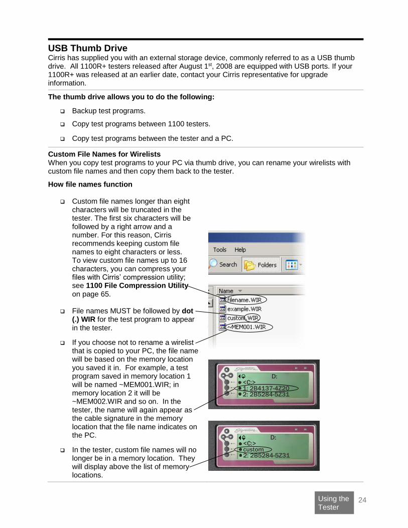
Custom file names longer than eight characters will be truncated in the tester. The first six characters will be followed by a right arrow and a number. For this reason, Cirris recommends keeping custom file names to eight characters or less. To view custom file names up to 16 characters, you can compress your files with Cirris’ compression utility; see 1100 File Compression Utility on page 65.
File names MUST be followed by dot (.) WIR for the test program to appear in the tester.
If you choose not to rename a wirelist that is copied to your PC, the file name will be based on the memory location you saved it in. For example, a test program saved in memory location 1 will be named ~MEM001.WIR; in memory location 2 it will be ~MEM002.WIR and so on. In the tester, the name will again appear as the cable signature in the memory location that the file name indicates on the PC.
In the tester, custom file names will no longer be in a memory location. They will display above the list of memory locations.
D: <C:> 1: 2B4137-4Z20 2: 2B5284-5Z31
D: <C:> custom 2: 2B5284-5Z31

25 Using the Tester
Creating Folders On your PC, you can organize test programs into folders and then copy the folders into the tester via the thumb drive.
How folders function
If you copy a folder to the tester, it will appear on the tester screen after you select the thumb or network drive letter. Press the folder’s button to view the files in the folder.
As with file names, folder names longer than eight characters will be truncated in the tester. The first six characters will be followed by a right arrow symbol and a number.
After you select a folder, you can press the button next to the symbol “<. .>” to take the screen up one folder level.
D: <C:> <folder> 1:
D: <C:> <newfol 1> 1:
D:\folder <C:> <. .> custom

26 Using the Tester
Managing Test Programs Saving test programs speeds up test setups and eliminates the need to maintain “known good” sample cables to reprogram the tester. You can load saved test programs, delete unwanted test programs, and copy test programs from one location to another. You can also import wirelists/ scripts that have been compressed using the 1100 File Compression Utility.
Saving a Test Program
You can save a test program after learning and verifying a sample cable OR after editing a test program.
To save the Loaded Test:
1. From the main menu, scroll down .
2. Press Manage Files.
3. Press Save.
4. Select:
a. drive letter (optional),
b. a folder (optional),
c. and a memory location.
Selecting a memory location saves the test program in the tester.
Note: Write down the test program information on the 1100R+ Cable Documentation or 1100R+ Test Program Location Listing (blank forms in appendix).
The selected drive displays here.
CABLE LEARNED Verify Test Save Test TEST: 39E92F-4Z020
SIGNATURE 1100R+ Manage Files Version Information Print: 39E92F-4Z020
C: <D:> <H:> 1:
H: <C:> <D:> <folder1>
H:/folder <D:> <. .> 1:

27 Using the Tester
Loading a Test Program
1. From the main menu, press Set Up Test Program.
2. Press Load Test.
3. Navigate to the location where the
test program has been saved.
4. Select the test program you wish to load.
To find the correct test, use the 1100H+ Test Program Location Listing or other documentation you may have used.
Deleting a Test Program 1. Return to the Main Menu.
2. Scroll down and press
Manage Files.
3. From the “Manage Files” menu, press Delete Files.
The 1100R+ allows you to mark the files you wish to delete enabling you to delete more than one file at a time. 4. Press Mark Files.
The Delete Marked button is disabled when no files are marked.
5. Navigate to the location of the test program(s) you wish to delete.
C: <E:> <F:> <Z:>
SIGNATURE 1100R+ Manage Files Version Information Print: 39E92F-4Z020
DELETE 0 FILES Mark Files Delete Marked CANCEL
C: <D:> 1: E3248D-2J8NH 2: B34892-6F8N0
28 Using the Tester
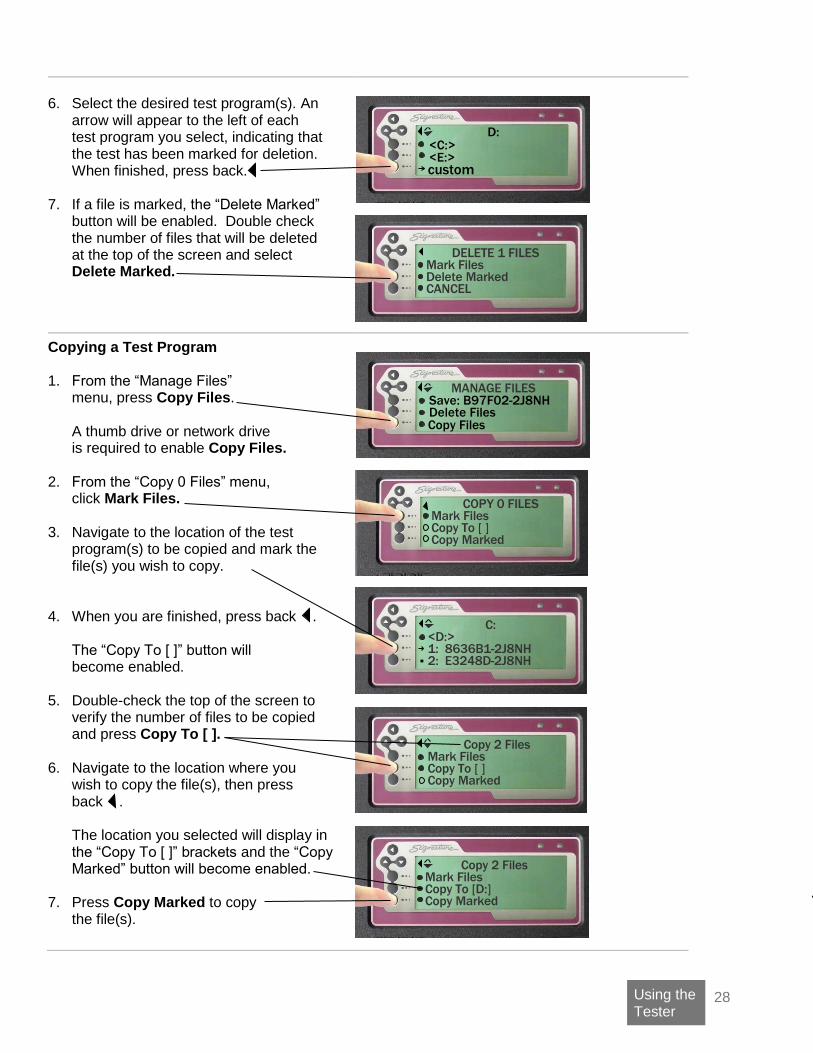
6. Select the desired test program(s). An arrow will appear to the left of each test program you select, indicating that the test has been marked for deletion. When finished, press back.
7. If a file is marked, the “Delete Marked”
button will be enabled. Double check the number of files that will be deleted at the top of the screen and select Delete Marked.
Copying a Test Program 1. From the “Manage Files”
menu, press Copy Files. A thumb drive or network drive is required to enable Copy Files.
2. From the “Copy 0 Files” menu, click Mark Files.
3. Navigate to the location of the test program(s) to be copied and mark the file(s) you wish to copy.
4. When you are finished, press back .
The “Copy To [ ]” button will become enabled.
5. Double-check the top of the screen to
verify the number of files to be copied and press Copy To [ ].
6. Navigate to the location where you wish to copy the file(s), then press back .
The location you selected will display in the “Copy To [ ]” brackets and the “Copy Marked” button will become enabled.
7. Press Copy Marked to copy
the file(s).
D: <C:> <E:>
custom
DELETE 1 FILES
Mark Files Delete Marked CANCEL
MANAGE FILES Save: B97F02-2J8NH Delete Files
COPY 0 FILES
Mark Files Copy To [ ] Copy Marked
Copy Files
C: <D:> 1: 8636B1-2J8NH 2: E3248D-2J8NH
Copy 2 Files Mark Files Copy To [ ] Copy Marked
Copy 2 Files Mark Files Copy To [D:] Copy Marked
29 Using the Tester
Importing Compressed Wirelists/Script Files You can only import wirelists or script files if they have been compressed with the “1100 File Compression Utility.” Files can be compressed into a bundle of files that can be imported into the tester simultaneously, or they can be compressed individually. Before attempting to import your files, see “1100 File Compression Utility” on page 65.
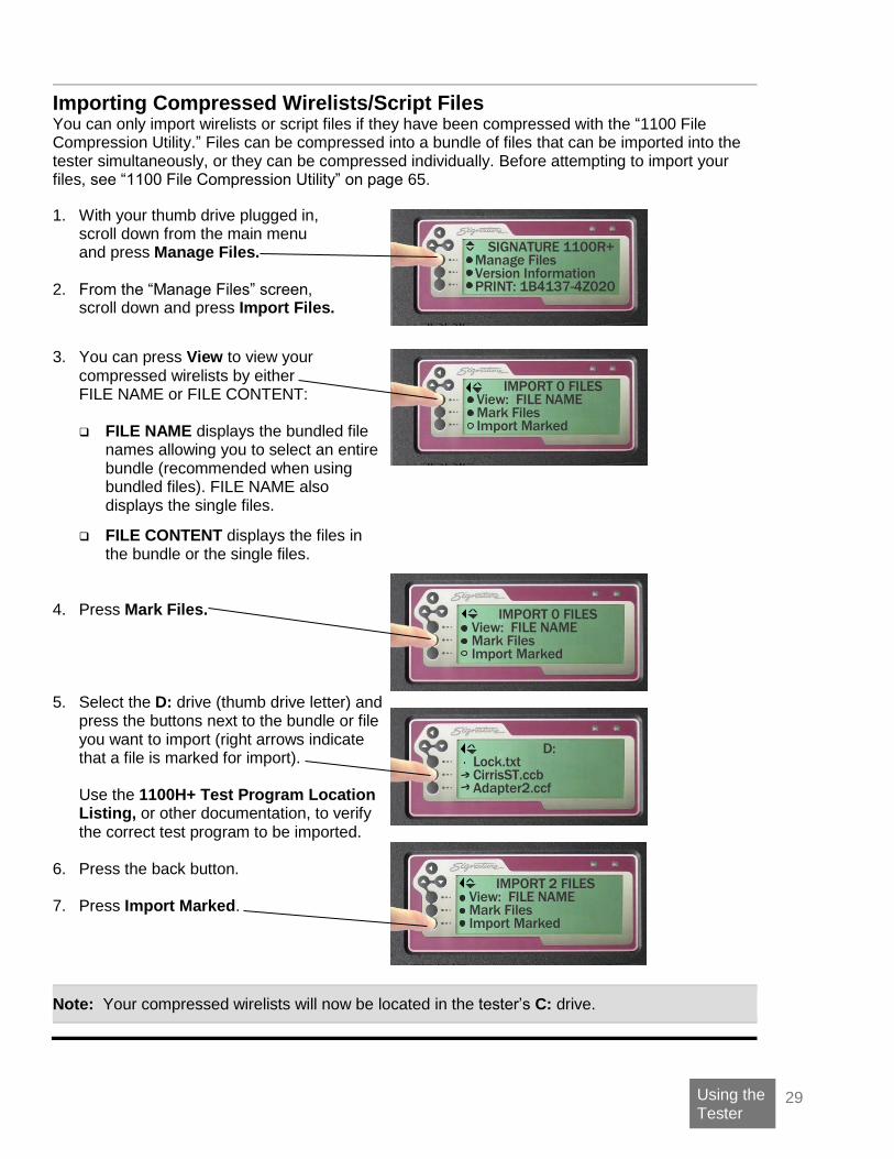
1. With your thumb drive plugged in, scroll down from the main menu and press Manage Files.
2. From the “Manage Files” screen,
scroll down and press Import Files.
3. You can press View to view your compressed wirelists by either FILE NAME or FILE CONTENT:
FILE NAME displays the bundled file
names allowing you to select an entire bundle (recommended when using bundled files). FILE NAME also displays the single files.
FILE CONTENT displays the files in the bundle or the single files.
4. Press Mark Files.
5. Select the D: drive (thumb drive letter) and press the buttons next to the bundle or file you want to import (right arrows indicate that a file is marked for import). Use the 1100H+ Test Program Location Listing, or other documentation, to verify the correct test program to be imported.
6. Press the back button.
7. Press Import Marked.
Note: Your compressed wirelists will now be located in the tester’s C: drive.
IMPORT 0 FILES View: FILE NAME Mark Files Import Marked
D: Lock.txt CirrisST.ccb Adapter2.ccf
IMPORT 2 FILES View: FILE NAME Mark Files Import Marked
IMPORT 0 FILES View: FILE NAME Mark Files Import Marked
SIGNATURE 1100R+ Manage Files Version Information PRINT: 1B4137-4Z020
30 CTLWIN
Using CTLWIN Included with your tester is the CTLWIN kit, which contains a software installation disk and PC-interface cable. CTLWIN is a Windows program that allows you to access test programs in the tester’s memory. By using CTLWIN, you can:
Copy/move test programs between an 1100R+ and a PC. Create custom point labels. Edit, create, and organize test programs on a PC. Create links and define components.
For CTLWIN installation instructions and PC requirements, see the Cirris Software Installation Guide.
Common Uses for CTLWIN
Copy Test Programs If you have multiple 1100R+ testers, you can create a test program on any tester, and use CTLWIN to copy the same test program to other testers.
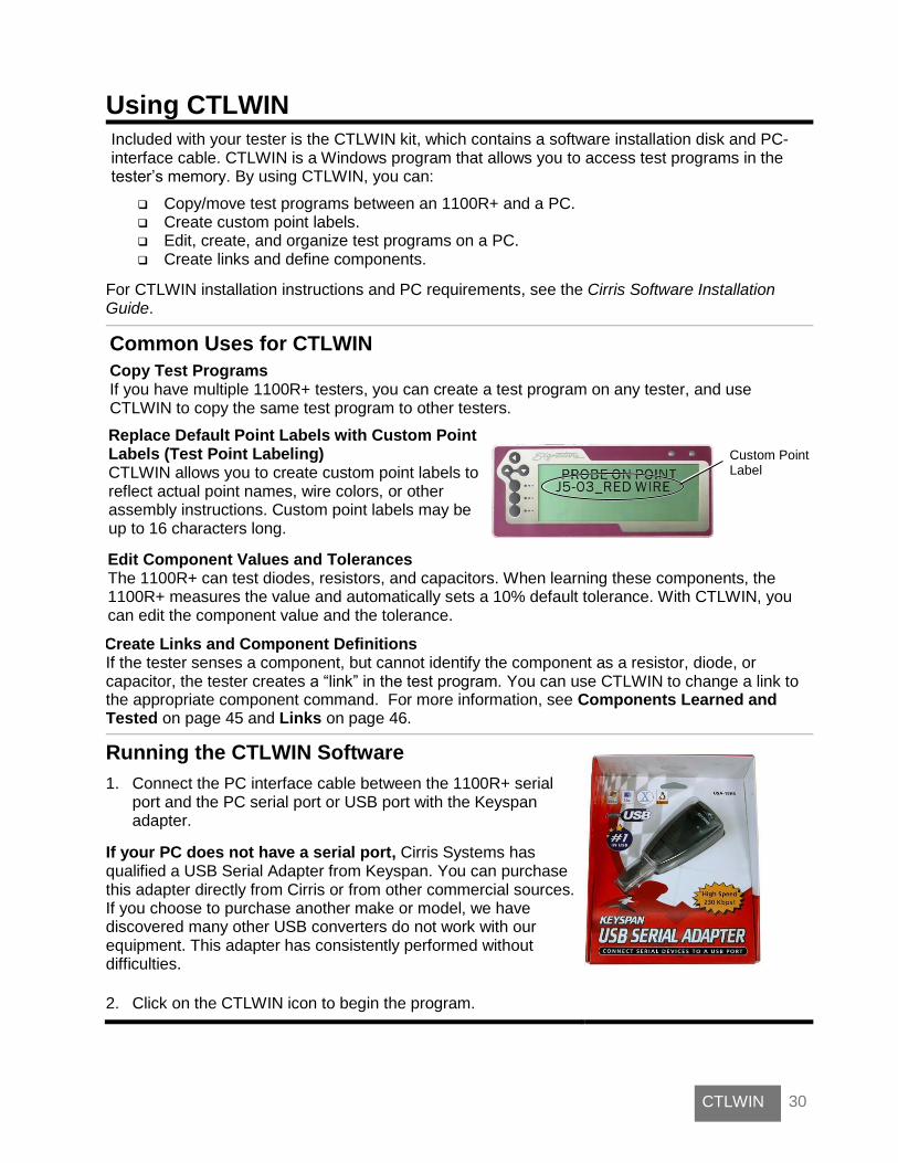
Replace Default Point Labels with Custom Point Labels (Test Point Labeling) CTLWIN allows you to create custom point labels to reflect actual point names, wire colors, or other assembly instructions. Custom point labels may be up to 16 characters long.
Edit Component Values and Tolerances The 1100R+ can test diodes, resistors, and capacitors. When learning these components, the 1100R+ measures the value and automatically sets a 10% default tolerance. With CTLWIN, you can edit the component value and the tolerance.
Create Links and Component Definitions If the tester senses a component, but cannot identify the component as a resistor, diode, or capacitor, the tester creates a “link” in the test program. You can use CTLWIN to change a link to the appropriate component command. For more information, see Components Learned and Tested on page 45 and Links on page 46.
Running the CTLWIN Software
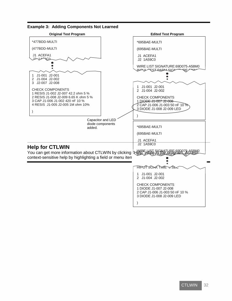
1. Connect the PC interface cable between the 1100R+ serial port and the PC serial port or USB port with the Keyspan adapter.
If your PC does not have a serial port, Cirris Systems has qualified a USB Serial Adapter from Keyspan. You can purchase this adapter directly from Cirris or from other commercial sources. If you choose to purchase another make or model, we have discovered many other USB converters do not work with our equipment. This adapter has consistently performed without difficulties.
2. Click on the CTLWIN icon to begin the program.
Custom Point Label

31 CTLWIN
Editing Test Programs The following examples illustrate how to edit test programs using CTLWIN:
Example 1: Changing Default Cable Description and/or Point Labels
Original Test Program Edited Test Program
Example 2: Modifying Component Test Values and Links
Original Test Program Edited Test Program
*477BDD-MULTI
(477BDD-MULTI
J1 ACEFA1 J2 1A59C0
1 J1-001 J2-0012 J1-004 J2-0023 J2-007 J2-008
CHECK COMPONENTS1 RESIS J1-002 J2-007 42.3 ohm 10 %2 RESIS J1-008 J2-009 6.64 K ohm 10 %3 CAP J1-006 J1-002 420 nF 10 %4 LINK J1-005 J2-005
)
*477BDD-MULTI
(477BDD-MULTI
J1 ACEFA1 J2 1A59C0
1 J1-001 J2-0012 J1-004 J2-0023 J2-007 J2-008
CHECK COMPONENTS1 RESIS J1-002 J2-007 42.2 ohm 5 %2 RESIS J1-008 J2-009 6.65 K ohm 5 %3 CAP J1-006 J1-002 420 nF 10 %4 RESIS J1-005 J2-005 1M ohm 10%
)
*DT SONAR MODULE
(984123-2J8NM
J1 D507F1
CONNECTION RESIS 10.0 ohm LV INSULATION RESIS 100 K ohm INSULATION RESIS 5.00 M ohm
1 J1-001 J1-002 2 J1-003 J1-004
LABELS J1-001 = HEADER_PIN1 J1-002 = HEADER_PIN2 J1-003 = RED_WIRE J1-004 = BLUE_WIRE
)
*984123-2J8NM
(984123-2J8NM
J1 D507F1
CONNECTION RESIS 10.0 ohm LV INSULATION RESIS 100 K ohm INSULATION RESIS 5.00 M ohm
1 J1-001 J1-002 2 J1-003 J1-004
)
Default point labels assigned custom point labels.
Cable description changed from the Cable Signature to a custom description.
Link command changed to a resistor command.
Learned resistor values and default tolerances edited.
32 CTLWIN
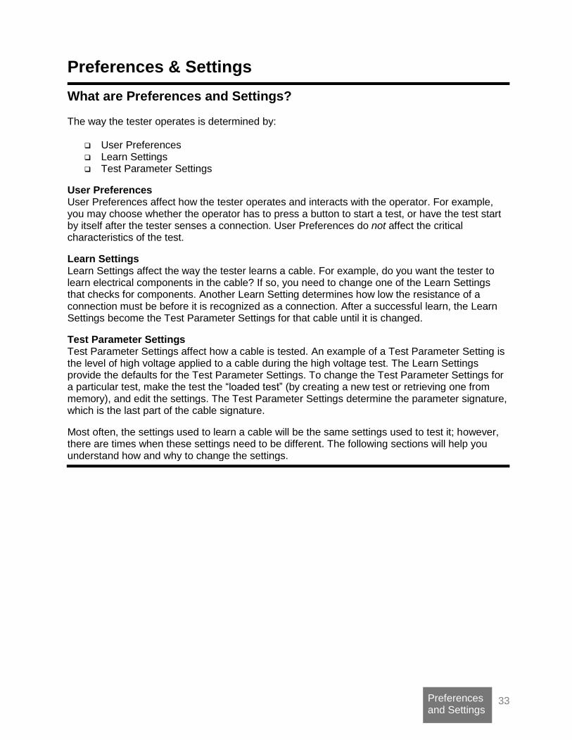
Example 3: Adding Components Not Learned
Original Test Program Edited Test Program
*477BDD-MULTI
(477BDD-MULTI
J1 ACEFA1 J2 1A59C0
1 J1-001 J2-0012 J1-004 J2-0023 J2-007 J2-008
CHECK COMPONENTS1 RESIS J1-002 J2-007 42.2 ohm 5 %2 RESIS J1-008 J2-009 6.65 K ohm 5 %3 CAP J1-006 J1-002 420 nF 10 %4 RESIS J1-005 J2-005 1M ohm 10%
)
Help for CTLWIN You can get more information about CTLWIN by clicking “Help” while in the program. Access context-sensitive help by highlighting a field or menu item and pressing “F1.”
*695BAE-MULTI
(695BAE-MULTI
J1 ACEFA1 J2 1A59C0
WIRE LIST SIGNATURE:69D075-A58M0INSUL TEST PARM SIGNATURE:2J6NH
1 J1-001 J2-0012 J1-004 J2-002
CHECK COMPONENTS1 DIODE J1-007 J2-0082 CAP J1-006 J1-003 50 nF 10 %3 DIODE J1-008 J2-009 LED
)
*695BAE-MULTI
(695BAE-MULTI
J1 ACEFA1 J2 1A59C0
WIRE LIST SIGNATURE:69D075-A58M0INSUL TEST PARM SIGNATURE:2J6NH
HIPOT SOAK TIME 0 SEC
1 J1-001 J2-0012 J1-004 J2-002
CHECK COMPONENTS1 DIODE J1-007 J2-0082 CAP J1-006 J1-003 50 nF 10 %3 DIODE J1-008 J2-009 LED
)
Capacitor and LED diode components added.
33 Preferences and Settings
Preferences & Settings
What are Preferences and Settings? The way the tester operates is determined by:
User Preferences Learn Settings Test Parameter Settings
User Preferences User Preferences affect how the tester operates and interacts with the operator. For example, you may choose whether the operator has to press a button to start a test, or have the test start by itself after the tester senses a connection. User Preferences do not affect the critical characteristics of the test.
Learn Settings Learn Settings affect the way the tester learns a cable. For example, do you want the tester to learn electrical components in the cable? If so, you need to change one of the Learn Settings that checks for components. Another Learn Setting determines how low the resistance of a connection must be before it is recognized as a connection. After a successful learn, the Learn Settings become the Test Parameter Settings for that cable until it is changed.
Test Parameter Settings Test Parameter Settings affect how a cable is tested. An example of a Test Parameter Setting is the level of high voltage applied to a cable during the high voltage test. The Learn Settings provide the defaults for the Test Parameter Settings. To change the Test Parameter Settings for a particular test, make the test the “loaded test” (by creating a new test or retrieving one from memory), and edit the settings. The Test Parameter Settings determine the parameter signature, which is the last part of the cable signature.
Most often, the settings used to learn a cable will be the same settings used to test it; however, there are times when these settings need to be different. The following sections will help you understand how and why to change the settings.

34 Preferences and Settings
1100 R+ Factory Defaults
The tables below list settings in the 1100R+ and their corresponding factory defaults.
User Preferences Factory Defaults
Test Mode CONTINUOUS
External Switch OFF
Fault Location OFF
Auto Start OFF
Test Count Good Only
Auto Print OFF
Digital Outputs Pin 7 = Good Light On Pin 8 = Bad Light On
Volume Medium
Low Voltage Settings Factory Defaults
Connection Resistance 10.0Ω
LV Insulation Resistance 100KΩ
Component Resistance OFF
Restoring Factory Default Preferences and Settings The factory defaults for User Preferences, Learn Settings, and Test Settings for the loaded test may be restored at any time.
1. From the main menu, press
Set Preferences.
2. Scroll down and press Set Factory Default.
3. Press RESET.
What Happens When a Cable is Tested? To understand how to set the preferences and settings, you need to have a basic idea of what happens when a cable is tested.
When the tester is set up with factory default preferences and settings, there are two parts to the test:
Note: The intermittent test will not occur if the User Preference Test Mode is set to SINGLE.
First Part Low Voltage Test
The tester checks the cable for opens, shorts, and miswires.
Second Part Intermittent Test
Until the cable is removed, the tester repeatedly runs low voltage tests to check for intermittent errors.
SIGNATURE 1100R+
Set Preferences Set Up Test Program TEST: DT Solar

35 Preferences and Settings
User Preferences User Preferences affect the way the tester performs and interacts with the operator, but do not affect the critical characteristics of the test. User Preferences can be changed in the tester.
Changing User Preferences
1. From the main menu, press Set Preferences.
2. Press the desired User Preference option,
see below: Set Test Methods allows you to access the following preferences:
• Test Mode
• External Switch
• Fault Location
• Auto Start
From this screen, you can also select Set Test Count and Set Auto Print.
3. Scroll down to access the following:
• Digital Outputs
• Factory Defaults
• Volume
Each 1100R+ User Preference is described on the following pages.
SIGNATURE 1100R+ Set Preferences Set Up Test Program TEST: Red Wire
SET USER PREFS
Set Test Methods Set Test Count Set Auto Print
SET USER PREFS Set Test Methods Set Test Count Set Auto Print
36 Preferences and Settings
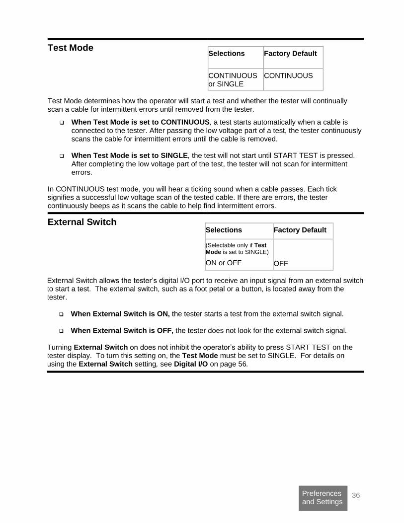
Test Mode
Selections Factory Default
CONTINUOUS or SINGLE
CONTINUOUS
Test Mode determines how the operator will start a test and whether the tester will continually scan a cable for intermittent errors until removed from the tester.
When Test Mode is set to CONTINUOUS, a test starts automatically when a cable is connected to the tester. After passing the low voltage part of a test, the tester continuously scans the cable for intermittent errors until the cable is removed.
When Test Mode is set to SINGLE, the test will not start until START TEST is pressed. After completing the low voltage part of the test, the tester will not scan for intermittent errors.
In CONTINUOUS test mode, you will hear a ticking sound when a cable passes. Each tick signifies a successful low voltage scan of the tested cable. If there are errors, the tester continuously beeps as it scans the cable to help find intermittent errors.
External Switch
Selections Factory Default
(Selectable only if Test Mode is set to SINGLE)
ON or OFF
OFF
External Switch allows the tester’s digital I/O port to receive an input signal from an external switch to start a test. The external switch, such as a foot petal or a button, is located away from the tester.
When External Switch is ON, the tester starts a test from the external switch signal.
When External Switch is OFF, the tester does not look for the external switch signal. Turning External Switch on does not inhibit the operator’s ability to press START TEST on the tester display. To turn this setting on, the Test Mode must be set to SINGLE. For details on using the External Switch setting, see Digital I/O on page 56.
37 Preferences and Settings
Fault Location
Selections Factory Default
ON or OFF ON
Fault Location determines which end of the cable displays open, short, or miswire first in the tested assembly.
When Fault Location is ON, the tester will display an asterisk “*” next to the pin or pins closest to the open or short.
When Fault Location is OFF, the fault location information will not be displayed. Because finding fault locations with the tester takes more time, only the fault locations of the first five errors will be displayed. If fault locations are required for more than five errors, the operator corrects the errors listed and retests the assembly. The tester locates opens using capacitance and shorts using resistance. For examples of errors where Fault Location is used, see Shorts on page 52 and Opens on page 53.
Note: For Fault Location to work well, the custom test fixturing should be no greater than one-half the length of the wires in the tested device.
Auto Start
Selections Factory Default
YES or NO NO
Auto Start allows you to have the tester automatically start testing when turned on.
If Auto Start is ON, the 1100R+ will automatically start testing using the loaded test in memory.
If Auto Start is OFF, the tester screen will show the main menu. This feature can be helpful when the tester is built into automated test equipment where the tester interface cannot be easily accessed. If you need to access the normal tester interface once Auto Start has been turned on, you may do so by turning on the tester and pressing CANCEL before the Auto Test countdown expires.

38 Preferences and Settings
Test Count
Selections Factory Default
GOOD CABLES ONLY or ALL CABLES
ALL CABLES
Test Count determines the types of tested cable counts listed in the test summary.
When Test Count is set to ALL CABLES, the test summary includes three counts: total cables tested, cables tested good, and cables tested bad.
When Test Count is set to GOOD CABLES ONLY, the test summary includes the count for good cables only.
The factory default ALL CABLES is more informative. However, some customers prefer to use GOOD CABLES ONLY.
Auto Print
Auto Print determines whether the tester will automatically print test results after each test.
When Auto Print is ON, you can select one of six reports that will automatically print test results. Depending on the type of selected report, the report will print after one of the following: (1) a good or bad cable is tested, (2) a good cable is tested, or (3) a bad cable is tested.
When Auto Print is OFF, the tester will print test results only when an operator presses PRINT TEST SUMMARY.
Auto Print allows you to select one of three standard reports or one of three custom reports. The standard reports are: All, Standard; Good, Standard; and Bad, Standard. The All, Standard prints a one-line report after each test, whether the cable tests good or bad. The Good, Standard prints a full page report after a cable tests good. The Bad, Standard prints a full page report after a cable tests bad. The reports autoall.rpt, autogood.rpt, and autobad.rpt can be customized if you purchased the scripting option. Being able to customize reports allows you to put your company name on the report and choose the data displayed on the report. Regardless of the type of report selected, you can print a Test Summary after any test when testing a run of cables. Remember, when you select a report, the same report will be used for all test programs until you change the report selection.
Selections Factory Default
ON or OFF OFF

39 Preferences and Settings
Digital Outputs
Selections Factory Default
Disable/Enable pins 5, 6, 7, 8, 10, 11
pin 7 = Cable Counted Good pin 8 = Cable Counted Bad
Digital Outputs determines how the tester controls the output pins on the the digital I/O port. The 1100R+ has six digital outputs which can drive an external device according to various “events” in the tester. These events occur as the tester powers up, learns a cable, tests a cable, and displays test results. Controlling an output line requires two triggering events. For more information, see
Digital I/O
on page 56.
Factory Defaults Factory Defaults restores the factory settings for the tester’s User Preferences and Learn Settings.
Volume
Selections Factory Default
Off, Low, Medium, High Medium
Volume allows you to turn off or adjust the volume of the tester. If you need louder sound, you can make an adjustment inside the unit. For more information, see Changing Volume and Display Controls on page 69.

40 Low Voltage Settings
Low Voltage Settings
Learn and Test Parameter Settings Learn Settings affect the way the tester learns a cable. After you learn a cable, the Learn Settings become the Test Parameter Settings for that cable, which determine how a cable is tested.
Changing Learn Settings 1. From the main menu, press
Set Up Test Program. 2. Press Create New Test.
3. Press Set Learn Settings.
4. Select the appropriate category.
5. Select the specific Learn Setting you want to change. You may need to scroll down to see all settings in the category.
6. Set the desired value for the Learn Setting. Some Learn Settings toggle between two values, and others scroll through a range of values.
7. Press ACCEPT or back to exit the
specific Test Setting. 8. Press back to exit the category of Learn
Settings. 9. Press back to exit the SET LEARN
SETTINGS menu.
Note: If you purchased SPC Data Collection, you can apply it to all learned tests it from the SET LEARN SETTINGS screen or to a single test from the EDIT screen, see “SPC Data Collection” on page 67.
SET UP TEST Create New Test Load Test EDIT: 39E92F-4Z020
SIGNATURE 1100R+ Set Preferences Set Up Test Program TEST: 39E92F-4Z020
SET LEARN SETTINGS Set Res Thresholds Set Components Set Up SPC

41 Low Voltage Settings
Changing Test Parameter Settings Note: You can only change the Test Parameter Settings of the loaded test program.
1. Make sure the test program you want to edit is loaded.
2. Load a new test program by learning a
cable or retrieving the test from memory.
3. From the main menu, press Set Up Test Program.
4. Press Edit to edit the loaded test program.
5. Select the category of test settings you want to edit.
6. Select the specific test setting you want to edit.
7. Set the desired value for the Test Parameter Setting. When selected, some Test Parameter Settings toggle between two values, while others scroll to the desired value.
8. Press ACCEPT or back to exit the specific test setting.
9. Press back to exit the category of test settings
10. Press back to exit the edit menu. If you made changes, a screen briefly confirms the changes in the loaded test program.
If you retrieve a loaded test from a memory location, the test is not updated until saved.
Each Learn and Test Parameter Setting used for setting Low Voltage Resistance thresholds is described on the following pages.
The cable signature or file name of the loaded test will display in the main menu.
SIGNATURE 1100R+ Set Preferences Set Up Test Program TEST: 39E92F-4Z020
SET UP TEST Create New Test Load Test EDIT: 39E92F-4Z020
EDIT: 39E92F-4Z020 Set Res Thresholds Set Up SPC View Other Settings
TEST EDITED Print Test Save Test TEST: 39E92F-720A8

42 Low Voltage Settings
Connection Resistance (Conn Res) How good are the connections in a cable? The Connection Resistance setting specifies the maximum resistance a connection can have, and still be considered good as opposed to having high resistance. When learning a cable, the connections in the cable must be lower in resistance than the Connection Resistance setting to be learned as connections. When testing a cable, the connections in the cable must be lower than the Connection Resistance setting to pass the test.
Guidelines on Connection Resistance
To allow for cable and tester tolerances, you should generally select a Connection Resistance at least 20% or 0.2 Ω (whichever is greater) above the resistance of the actual connections.
Over time, heavily used adapters can develop worn contacts, which will add to the connection resistance measurement. Cirris recommends replacing worn adapters before they affect the measured connection resistance and create high resistance errors. If you must use adapters with substantial wear, you will have to increase the Connection Resistance setting to get cables to pass.
The 1100R+ can measure the actual connection resistance and give you a suggested value for the Connection Resistance setting. To Calculate a Suggested Connection Resistance Setting: 1. Attach a sample cable.
2. From the main menu, press Create New Test, Set Learn Settings, Set Lrn Res Thrsholds, and Calculate Conn Res.
3. The tester measures the resistance of each wire and displays a Suggested Res value, which is 20% greater than the highest resistance in the sample cable.
To help determine a better Connection Resistance setting, measure the variances of several sample cables, connect each cable and press Calc New Sample.
Note: Use Calculate Conn Res with caution. A bad sample cable may cause the suggested value to be higher than it should be.
Zero Resistance Connection
Resistance
Setting
Infinite Resistance
Selections Factory Default
0.1Ω-100KΩ, 500KΩ 1MΩ, 5MΩ
10.0Ω
HIGH RESISTANCE GOOD OPEN

43 Low Voltage Settings
LV Insulation Resistance
(LV Insul Res)
The LV Insulation Resistance setting only affects the low voltage test where the basic cable pattern and gross insulation problems are identified. This setting determines how high the insulation resistance must be between cable nets to pass the low voltage test. The tester displays SHORT for an unintended resistance between nets that is less than the LV Insulation Resistance setting. In addition, the LV Insulation Resistance setting determines at what resistance intended connections are considered open; as opposed to having high resistance. Guidelines on LV Insulation Resistance The factory default of 100KΩ should work well for most cable testing applications. The higher you raise the LV Insulation Resistance setting, the longer it takes for the tester to perform the low voltage part of the cable test.
Note: Resistances above the LV Insulation Resistance setting will be ignored during a learn.
Selections Factory Default
0.1Ω-100KΩ, 500KΩ, 1MΩ, 5MΩ
100KΩ
Zero Resistance LV Insulation
Resistance
Setting
Infinite Resistance Connection
Resistance
Setting
Zero Resistance LV Insulation
Resistance
Setting
Infinite Resistance
PASSES LV SHORT PASSES LV SHORT
HIGH RESISTANCE GOOD OPEN
44 Low Voltage Settings
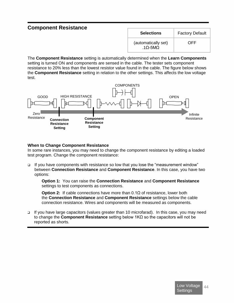
Component Resistance
The Component Resistance setting is automatically determined when the Learn Components setting is turned ON and components are sensed in the cable. The tester sets component resistance to 20% less than the lowest resistor value found in the cable. The figure below shows the Component Resistance setting in relation to the other settings. This affects the low voltage test. When to Change Component Resistance In some rare instances, you may need to change the component resistance by editing a loaded test program. Change the component resistance: If you have components with resistance so low that you lose the “measurement window”
between Connection Resistance and Component Resistance. In this case, you have two options:
Option 1: You can raise the Connection Resistance and Component Resistance settings to test components as connections.
Option 2: If cable connections have more than 0.1Ω of resistance, lower both the Connection Resistance and Component Resistance settings below the cable connection resistance. Wires and components will be measured as components.
If you have large capacitors (values greater than 10 microfarad). In this case, you may need
to change the Component Resistance setting below 1KΩ so the capacitors will not be reported as shorts.
Selections Factory Default
(automatically set) .1Ω-5MΩ
OFF
Zero Resistance Component
Resistance
Setting
Infinite Resistance Connection
Resistance
Setting
COMPONENTS
HIGH RESISTANCE GOOD OPEN

45 Component Setting & Test
Component Setting & Test
Learn Components
Selections Factory Defaults
On or Off for: Resistors, Diodes, Capacitors, 4W Kelvin
Off for all Component types
The Learn Components setting is found in Learn Settings. Learn Components determines whether the tester looks for the existence of components when learning a cable. From the main menu, select Set Up Test Program, Create New Test, Set Learn Settings, and Set Components. If you learn a cable with components, the Parameter Signature (the last five digits of the Cable Signature) is displayed as MULTI.
When Learning an Assembly with Components After learning a cable assembly, the technician should verify the test program (see page 17). When verifying the test program of a cable assembly with components, you must assure that each component in the learned cable assembly is identified with the appropriate component or link command. The following topics in this section can help you understand how to do this.
Components Learned and Tested
The 1100R+ can learn and test resistors, capacitors, diodes, and 4-Wire Kelvin. Though 4-Wire Kelvin is not technically a component, the tester interface uses the term “component” to describe certain electrical characteristics between points. Some components may not be learned, but can be effectively tested if the test program is edited using CTLWIN. The chart below compares learns and test capability for the tester.
Learn Test
Resistors: 0.1Ω to 100KΩ >100KΩ to 5MΩ learn as links.
Resistors: 0.1Ω to 1MΩ
Capacitors: 400 nF to 100 μF Capacitors: 5nF to 100F ± 10% ± 20pF (relative measurements to 10pF)
Common silicon diodes
Zener diodes: Learn as a standard diode as long as zener voltage > 4V
Common silicon diodes
Zener diodes: Test as standard diode as long as zener voltage > 4V
LEDs
Note: The tester does not learn or test germanium diodes, Shottky diodes, or diodes in series with some resistors. The tester recognizes these components as opens and shorts.
4-Wire Kelvin: 0.001 to 10.0 % 0.001 Same as Learn

46 Component Setting & Test
Links
In some cases, the tester may sense the electrical characteristics of a component, but cannot determine if the component is a resistor, diode, or capacitor. When this occurs, the tester creates a “link” in the test program. During the low voltage test, the tester assures the linked points have a higher resistance than the Component Resistance Setting. Links may be created automatically by the tester or by the technician setting up the test.
Links created automatically by the tester When verifying a learned test program, a technician may recognize that the tester created links in the test program’s net list. In some cases, the tester may have assigned a component a link because it was outside the tester’s learn range. However, in some instances, the component can still be effectively tested if the technician uses CTLWIN to edit the links assigned by the tester. For example, in order to speed the learn process for the majority of cables, the tester does not
learn component resistances higher than 100KHowever, the tester does assign links to
resistors with values above 100K and below the Low Voltage Insulation Resistance setting,
which can be set up to 5M. If the tester creates a link for a resistance between 100Kand
1M, the technician can use CTLWIN to replace the link with a resistance command, thus testing the resistance value.
Links created by the technician In some instances, the technician setting up the test program may need to use CTLWIN to create links in the test program.

47 Component Setting & Test
4-Wire Kelvin The 1100R+ can be used to perform 4-Wire Kelvin resistance measurements. This capability allows you to null out fixturing resistance and measure very low resistances (down to 0.001 Ω). The standard 2-wire resistance measurement requires a single test point for every connection on the device-under-test. The 4-wire measurement requires two correctly paired test points for every connection. One test point supplies current (typically referred to as “force”), while the other senses voltage (typically referred to as “sense”). You may connect force to sense on the contact mechanism to the device-under-test and see a very small interface resistance. However, if you bring force and sense together directly on the contact of the device-under-test, you will eliminate all sources of interface resistance. This extra effort may not be feasible. For more information, see Four Wire Kelvin Testing at http://www.cirris.com/testing/resistance/fourwire.html.
Note: 2-wire and 4-wire testing can be put into any combination on the 1100R+ tester.
Building 4-Wire Fixturing
For the purpose of 4-wire testing, the 1100R+ test points are considered either Type 1 (T1) or Type 2 (T2) points. Each 4-wire pair from the tester must have one of each point. The tester uses T1 points as either force or sense; it uses T2 points as the compliment. While you can use any standard adapter to run 4-wire fixturing from the tester, Cirris suggests using one of the Cirris AHED series adapters. The AHED adapters map T1 and T2 points in a uniform, alternating pattern (as shown on the next page). The probe can also be used to identify T1 and T2 points as described further in this section.
The 1100R+ tester must learn a 4-wire fixture. When the fixture is learned, the first scanned point of each 4-wire pair becomes the visible point in the net list. Both test points are listed below the net list in the 4-wire Kelvin Pairs.
48 Component Setting & Test
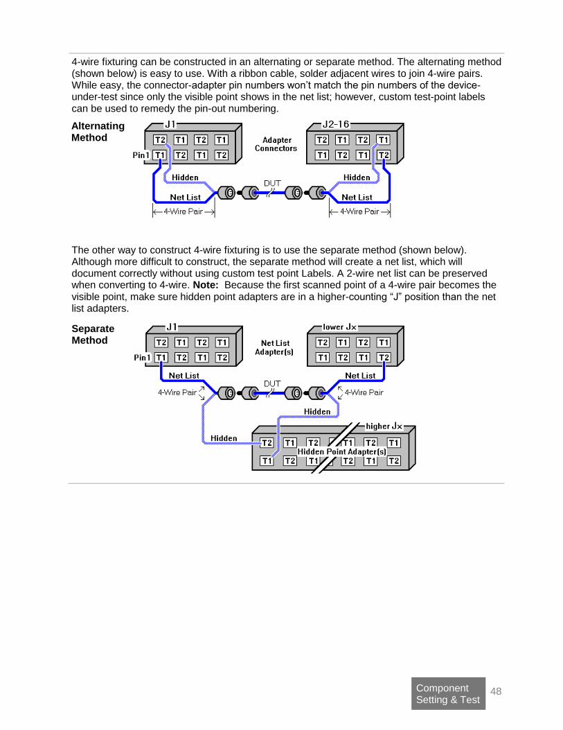
4-wire fixturing can be constructed in an alternating or separate method. The alternating method (shown below) is easy to use. With a ribbon cable, solder adjacent wires to join 4-wire pairs. While easy, the connector-adapter pin numbers won’t match the pin numbers of the device-under-test since only the visible point shows in the net list; however, custom test-point labels can be used to remedy the pin-out numbering.
Alternating Method
The other way to construct 4-wire fixturing is to use the separate method (shown below). Although more difficult to construct, the separate method will create a net list, which will document correctly without using custom test point Labels. A 2-wire net list can be preserved when converting to 4-wire. Note: Because the first scanned point of a 4-wire pair becomes the visible point, make sure hidden point adapters are in a higher-counting “J” position than the net list adapters.
Separate Method

49 Component Setting & Test
The Location of Kelvin Points in Fixturing
The location where the 4-wire pair physically joins the test-point connection of the device-under-test is called a Kelvin point.
Each 4-wire measurement requires two Kelvin points: one at each end of the tested device. The Kelvin points should be placed as close to the device-under-test as possible. This is because the 4-wire test measures from Kelvin point to Kelvin point, so any contact and lead resistance between the Kelvin points is added to the resistance measurement of the device-under-test. The diagram below shows how the location of the Kelvin points will affect the resistance measurement of the device-under-test.
DUT #1: The measurement is only of the device-under-test. This is ideal, but in real situations, it may be impossible.
DUT #2: The measurement includes part of the fixture. Warning! If a lot of the fixture is between a Kelvin point and the device-under-test, the 4-wire test will be considerably compromised.
DUT #3: The measurement tests only part of the device-under-test. For example, by using probe pins, you can eliminate the resistance of a connector from the measurement.
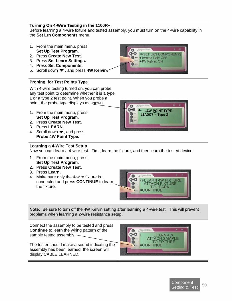
50 Component Setting & Test
Turning On 4-Wire Testing in the 1100R+ Before learning a 4-wire fixture and tested assembly, you must turn on the 4-wire capability in the Set Lrn Components menu.
1. From the main menu, press
Set Up Test Program. 2. Press Create New Test. 3. Press Set Learn Settings. 4. Press Set Components. 5. Scroll down , and press 4W Kelvin.
Probing for Test Points Type
With 4-wire testing turned on, you can probe any test point to determine whether it is a type 1 or a type 2 test point. When you probe a point, the probe type displays as shown. 1. From the main menu, press
Set Up Test Program. 2. Press Create New Test. 3. Press LEARN. 4. Scroll down , and press
Probe 4W Point Type.
Learning a 4-Wire Test Setup Now you can learn a 4-wire test. First, learn the fixture, and then learn the tested device.
1. From the main menu, press Set Up Test Program.
2. Press Create New Test. 3. Press Learn. 4. Make sure only the 4-wire fixture is
connected and press CONTINUE to learn the fixture.
Note: Be sure to turn off the 4W Kelvin setting after learning a 4-wire test. This will prevent problems when learning a 2-wire resistance setup.
Connect the assembly to be tested and press Continue to learn the wiring pattern of the sample tested assembly. The tester should make a sound indicating the assembly has been learned; the screen will display CABLE LEARNED.
4W POINT TYPE J1A007 = Type 2
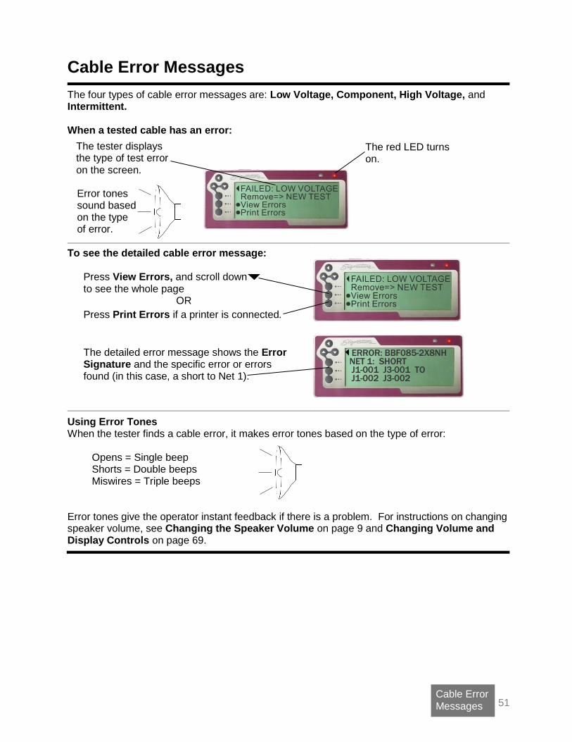
51 Cable Error
Messages
Cable Error Messages
The four types of cable error messages are: Low Voltage, Component, High Voltage, and Intermittent. When a tested cable has an error:
To see the detailed cable error message:
Press View Errors, and scroll down to see the whole page
OR
Press Print Errors if a printer is connected.
The detailed error message shows the Error Signature and the specific error or errors found (in this case, a short to Net 1).
Using Error Tones When the tester finds a cable error, it makes error tones based on the type of error:
Opens = Single beep Shorts = Double beeps Miswires = Triple beeps
Error tones give the operator instant feedback if there is a problem. For instructions on changing speaker volume, see Changing the Speaker Volume on page 9 and Changing Volume and Display Controls on page 69.
The red LED turns on.
Error tones sound based on the type of error.
The tester displays the type of test error on the screen.
ERROR: BBF085-2X8NH NET 1: SHORT J1-001 J3-001 TO J1-002 J3-002
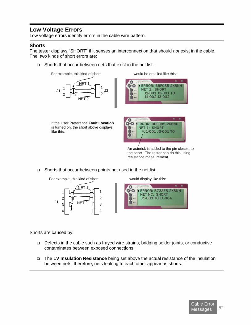
52 Cable Error
Messages
Low Voltage Errors Low voltage errors identify errors in the cable wire pattern.
Shorts The tester displays “SHORT” if it senses an interconnection that should not exist in the cable. The two kinds of short errors are:
Shorts that occur between nets that exist in the net list.
For example, this kind of short
would be detailed like this:
If the User Preference Fault Location
is turned on, the short above displays like this.
An asterisk is added to the pin closest to the short. The tester can do this using resistance measurement.
Shorts that occur between points not used in the net list.
For example, this kind of short
would display like this:
Shorts are caused by:
Defects in the cable such as frayed wire strains, bridging solder joints, or conductive contaminates between exposed connections.
The LV Insulation Resistance being set above the actual resistance of the insulation
between nets; therefore, nets leaking to each other appear as shorts.
ERROR: B73AE5-2X8NH NET NC: SHORT J1-003 TO J1-004
NET 1
NET 2
1
2
1
2 J3 J1
NET 1
NET 2
1
2
3
4
J1
1
2
3
4
ERROR: BBF085-2X8NH NET 1: SHORT J1-001 J3-001 TO J1-002 J3-002
ERROR: BBF085-2X8NH NET 1: SHORT *J1-001 J3-001 TO

53 Cable Error
Messages
Opens The tester displays “OPEN” if it does not sense an interconnection that should exist in the cable.
For example, if this is correct and this was the error, the error would display like this:
If the User Preference Fault Location is turned on, the open above would be displayed like this. An asterisk is added to the pin closest to the open. The tester can do this by sensing the lower capacitance of the unconnected pin.
Opens are caused by:
Defects in the cable, such as missing or cut wires, defective or un-inserted connector contacts, or cold solder joints.
The LV Insulation Resistance setting being set lower than the actual resistance of a wire connection.
The Component Resistance setting being set lower than an electronic component in the cable.
Miswires The tester displays “MISWIRE” if it senses that a contact, which should have a valid connection, is connected to an incorrect contact.
As shown in this example, the miswire error is indicated as a contact “OPEN” to where it should go, and “MISWIRE” to where it does go.
Miswires are caused by:
Wiring errors in the cable.
ERROR:E8C464-2X8NH NET 1: OPEN J1-001 TO J3-001 MISWIRE J3-002
NET 1
NET 2
1
2
1
2 J3 J1 J1
1
2 J3 pr
1
2
ERROR:E8C464-2X8NH NET 2: OPEN J1-002 TO J3-002 MISWIRE J3-001
ERROR: 1C4873-2X8NH NET 2: OPEN J1-002 TO J3-002
NET 1
1
2 J1
1
2 J3 pr
NET 1
NET 2
1
2
1
2 J3 J1
and these were the errors, the error message would look like this: For example, if this is correct
ERROR: 1C4873-2X8NH NET 2: OPEN * J1-002 TO J3-002

54 Cable Error
Messages
High Resistance Errors The tester displays a High Resistance error when a cable interconnection has too much resistance.
High Resistance errors are caused by:
Defects in the cable, such as partially inserted or dirty connector contacts or poorly crimped wires.
High resistance in the adapter or tester connector contacts. In this case, the 1100R+
connectors that interface with the adapters may be worn or damaged and need to be replaced.
A “Connection Resistance” setting too low for the tested assembly. In this case, the wire
or contact resistance is greater than the “Connection Resistance” setting, but less than the “LV Insulation Resistance” setting.
A component, such as a resistor, exists in the cable which has not been learned in the
test program.
Intermittent Errors The 1100R+ looks for Intermittent Errors in a cable during the Intermittent Test. Intermittent errors include the same short and open errors found in the low voltage cable test as described in the previous section. What’s the difference between Intermittent Errors and Low Voltage Errors? To be an Intermittent Error, the tester must sense the cable wire pattern:
1. Was good,
2. Then changed to bad,
3. Then changed back to good.
Intermittent errors are caused by:
Cable defects that are detected only when the cable is moved or wiggled during the test.
The ultimate causes are the same as those described in the previous section for opens and shorts.
55 Cable Error
Messages
Component Errors The 1100R+ displays a component error if it senses a problem with an electrical component programmed into the cable test. The tester detects component errors during the low voltage cable test.
Bad Resistor and Bad Capacitor The tester displays these messages when it senses a component with a measured value outside the tolerance for the component programmed in the cable test.
Possible causes:
The wrong value component is installed in the cable.
The correct component is installed, but is out of tolerance.
The connection to the component has high resistance and therefore, has affected the tester’s ability to correctly measure the component value.
Missing Resistor, Missing Capacitor, and Missing Diode The tester displays these messages when it does not sense a component where it should be in the cable.
Possible causes:
A connection to the component is open.
The component has not been installed, is missing, or has a resistance greater than 1 MΩ.
Bad Diode The tester displays this message when it senses a defective diode condition.
Possible causes are:
The diode’s forward or reverse bias voltage drop is out of tolerance.
The installed diode is outside the measurement capability of the tester.
Reversed Diode The tester displays this message when it senses a diode’s orientation is reversed. Possible cause:
The diode is reversed in the cable.
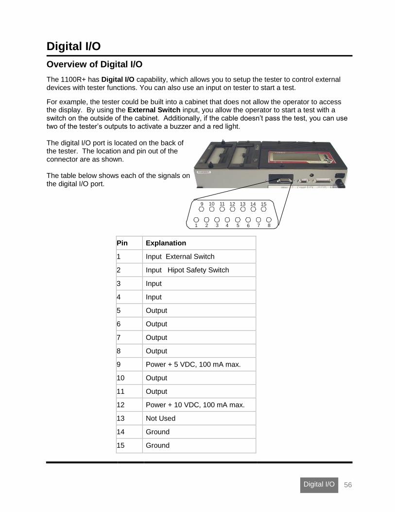
56 Digital I/O
Digital I/O
Overview of Digital I/O
The 1100R+ has Digital I/O capability, which allows you to setup the tester to control external devices with tester functions. You can also use an input on tester to start a test.
For example, the tester could be built into a cabinet that does not allow the operator to access the display. By using the External Switch input, you allow the operator to start a test with a switch on the outside of the cabinet. Additionally, if the cable doesn’t pass the test, you can use two of the tester’s outputs to activate a buzzer and a red light.
The digital I/O port is located on the back of the tester. The location and pin out of the connector are as shown. The table below shows each of the signals on the digital I/O port.
9 10 11 12 13 1514
1 2 3 4 5 6 7 8
Pin Explanation
1 Input External Switch
2 Input Hipot Safety Switch
3 Input
4 Input
5 Output
6 Output
7 Output
8 Output
9 Power + 5 VDC, 100 mA max.
10 Output
11 Output
12 Power + 10 VDC, 100 mA max.
13 Not Used
14 Ground
15 Ground

57 Digital I/O
Inputs There are four inputs in the 1100R+. VDC logic is typically used to control an input; however, any VDC up to a nominal 24 volts may be used. Inputs used for the tester’s External Switch (and Hipot Safety Switch capability on 1100H+ testers) are described below. If needed, other inputs can be assigned by using the scripting option.
Using the External Switch Input The 1100R+ has the ability to start a test based on input from an external switch, such as a foot pedal or sensor, in automated test equipment. To use the External Switch input, you must set the User Preference External Switch to YES. For more information, see User Preferences on page 35 and External Switch on page 36. The External Switch input is on pin 1 of the digital I/O connector. If a VDC +5 (logic high) is applied to pin 1, and then removed, this high to low transition will cause the tester to behave as if START TEST were pressed. You can use the VDC +5 power source on the I/O connector to supply the VDC +5 through the switch circuit as shown below. Do not apply a VAC to the input.
Pin 9 DC +5 Volts
Pin 1External Switch Input
Using the Hipot Safety Switch Input on the 1100H+ Tester (use this as a reference). The 1100H+ allows you to regulate the application of the hipot portion of the test by closing an external Hipot Safety Switch. Palm switches (a foot pedal or sensor wired in series) in automated test equipment can be used. To use the Hipot Safety Switch input, you must first set the users preference Safety Switch to YES. For more information, see User Preferences on page 35. The Hipot Safety Switch input is on pin 2 of the digital I/O connector. When a VDC +5 (logic high) is applied to pin 2, the tester allows the hipot test to proceed. You can use the VDC +5 power source on the digital I/O connector to supply the VDC +5 through the switch circuit. Do not apply a VAC to the input. Refer to the schematic above for application, using pin 2 instead of pin 1 for the safety switch.
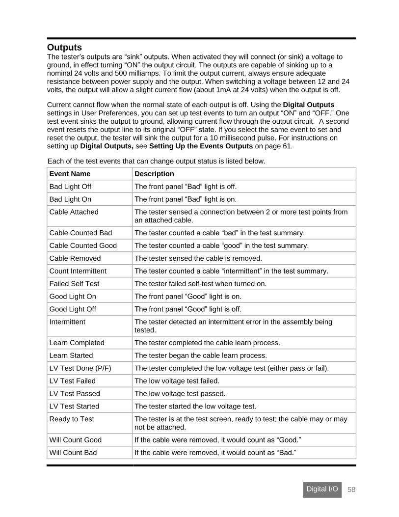
58 Digital I/O
Outputs The tester’s outputs are “sink” outputs. When activated they will connect (or sink) a voltage to ground, in effect turning “ON” the output circuit. The outputs are capable of sinking up to a nominal 24 volts and 500 milliamps. To limit the output current, always ensure adequate resistance between power supply and the output. When switching a voltage between 12 and 24 volts, the output will allow a slight current flow (about 1mA at 24 volts) when the output is off.
Current cannot flow when the normal state of each output is off. Using the Digital Outputs settings in User Preferences, you can set up test events to turn an output “ON” and “OFF.” One test event sinks the output to ground, allowing current flow through the output circuit. A second event resets the output line to its original “OFF” state. If you select the same event to set and reset the output, the tester will sink the output for a 10 millisecond pulse. For instructions on setting up Digital Outputs, see Setting Up the Events Outputs on page 61.
Each of the test events that can change output status is listed below.
Event Name Description
Bad Light Off The front panel “Bad” light is off.
Bad Light On The front panel “Bad” light is on.
Cable Attached The tester sensed a connection between 2 or more test points from an attached cable.
Cable Counted Bad The tester counted a cable “bad” in the test summary.
Cable Counted Good The tester counted a cable “good” in the test summary.
Cable Removed The tester sensed the cable is removed.
Count Intermittent The tester counted a cable “intermittent” in the test summary.
Failed Self Test The tester failed self-test when turned on.
Good Light On The front panel “Good” light is on.
Good Light Off The front panel “Good” light is off.
Intermittent The tester detected an intermittent error in the assembly being tested.
Learn Completed The tester completed the cable learn process.
Learn Started The tester began the cable learn process.
LV Test Done (P/F) The tester completed the low voltage test (either pass or fail).
LV Test Failed The low voltage test failed.
LV Test Passed The low voltage test passed.
LV Test Started The tester started the low voltage test.
Ready to Test The tester is at the test screen, ready to test; the cable may or may not be attached.
Will Count Good If the cable were removed, it would count as “Good.”
Will Count Bad If the cable were removed, it would count as “Bad.”

59 Digital I/O
Output Examples
Controlling an LED Let’s say you want to turn on an LED while a cable is attached to the tester. In the User Preference Set Digital Output, you can choose to configure one of the outputs. In this case, choose output pin 10. For this output pin, select Cable Attached to set, and Cable Removed to reset the output. In this example, the LED requires only 20 mA; therefore, we can use the +5 VDC supply on the digital I/O port to power our circuit. Use a resistor in series with the LED to limit the current going through it.
Pin 9DC +5 Volts
Pin 10Output
Resistor
LED
How do you choose the resistor? The LED in this instance has a forward bias voltage-drop of two volts; therefore, three volts must drop across the current-limiting resistor. Knowing voltage drop and current through the circuit, Ohms Law can be used to determine the resistor value.
R =V
I=
3 Volts
0.020 Amps= 150 Ohms
When the cable is attached, the tester will pull the output to ground allowing current to flow in the circuit, and the LED will turn on. When the cable is removed, current though the output will stop, and the LED will turn off.
Turning on a Light Let’s say that instead of an LED you want to turn on a light bulb powered from a 120 VAC wall outlet. A relay can be used to control the light bulb. In this example, we select a relay that has a coil voltage of 12 volts and draws less than 100 milliamps so we can use the +12 VDC power supply on the tester. The relay circuit is as shown.
Pin 6 Output
Diode
Relay
Pin 12 +12 VDC
A diode, such as a 1N4002, is added across the relay to protect the digital I/O port from the reverse current created from the coil when the output turns off.

60 Digital I/O
Activating an Air Valve Let’s say you want to control an air valve for equipment that will automatically stamp “tested good” on each assembly that passes a test. In the User Preference Set Digital Output, you can select Cable Counted Good to both set and reset the output. Remember, if the same event is selected for set and reset, the tester will sink the output for a 10-millisecond pulse. In this case, a pulse is all we need to make our stamp mechanism function. In the example below, the solenoid for the air piston requires VDC 24 and 300 milliamps (the coil resistance is 80 ohms).
Note: The digital I/O port can only supply 100 milliamps at either VDC 5 or 10; however, the output can sink up to 24 VDC. In this case, you can use an external power supply for the valve circuit as shown below.
Pin 5Output
Pins 14 & 15Ground
ValveSolinoid
DC PowerSupply
+24 V
Diode
In this example, a 1N4002 is added across the relay to protect the digital I/O port from the reverse current created from the coil when the output turns off.

61 Digital I/O
Setting up the Events Outputs The 1100R+ has six outputs that can drive an external device according to various “events” in the tester. These events occur as the tester powers up, learns a cable, tests a cable, and displays the test results. Controlling an output line requires two triggering events.
1. From the main menu, press Set Preferences.
2. Scroll down and press Set Digital Outputs.
3. Scroll up or down to the digital output pin
you want to setup.
4. Press S (set).
5. Scroll up or down to the test event you
want to start the operation of the output device; press Accept.
6. Press R (reset).
7. Scroll up or down to the event needed to stop the operation of the output device and press Accept.
8. Press back to leave the Digital Output
selection menu.
The S event sets (or sinks) the output pin to ground thereby allowing current to flow through the output circuit.
The R event resets the output pin to the original no current flowing state.
Note: Two of the outputs are factory enabled with default triggers. The pin 7 output is set with “Good Light On” and reset with “Good Light Off.” Pin 8 is set with “Bad Light On” and reset with “Bad Light Off.”
62 Tester Configuration
Tester Configuration
1100 Upgrade Application Using the “1100 Upgrade Application,” you can update the tester software and change the interface language. English and Spanish are now available for the1100R+ tester. Other languages may be available in the future. To update the software and select an interface language, you need to obtain a file containing the “1100 Upgrade Application” and the current 1100 tester software. You can access this file from cirris.com, or it can be emailed or mailed to you. You will need a PC that can provide a serial interface for your tester. If you do not have a PC with a serial port, you may use a USB port with a Cirris qualified Keyspan USB-to-serial adapter. A serial cable is provided with the CTLWIN kit you received with the tester. To download the upgrade file from cirris.com:
1. Type the URL www.cirris.com/1100r in your web browser.
2. Log in or create a user account.
3. On the 1100H+ page select the Software tab.
4. Click on the file 1100 utilities under Downloads.
5. In Windows Explorer, navigate to the downloads folder and find the 1100 Utilities zip file. Right-click and select Extract All. In the window that opens, click Extract in the bottom right corner. When the file finishes loading, double click 1100_Utilities.
6. In the File Download dialogue box that comes up, click Run to install the 1100 Upgrade software, or click Save if you will be installing the software on other stations.
The software installation should take a few seconds. When the software is installed, an 1100 Upgrade utility icon will appear on the computer desktop.
To run the 1100 Upgrade Application:
With the tester turned ON and connected to the PC, double click the 1100 Upgrade Utility icon. In the Download Utility screen, select a language and click Download. When the download is complete the tester will reboot with the selected language and updated software.

63 Tester Configuration
1100 Utilities Application This Application has two tabs. The “Security Manager” tab allows you to lock or unlock specific tester menu selections. If scripting has been purchased, you can enable the scripting option in the “Option Manager” tab.
The PC you connect to the tester must have a serial port or use a USB-to-serial adapter. Cirris has qualified the Keyspan USB-to-serial adapter; other adapters may work correctly. You can purchase this adapter from a local distributor or from Cirris. You must install the 1100 Utilities software on a PC. This software can be downloaded from cirris.com. Additionally, the tester must have version 4.5a software or higher installed to utilize this feature. To download and install the 1100 Utilities software:
1. Type the URL www.cirris.com/1100r in your web browser.
2. Log in or create a user account.
3. On the 1100H+ page select the Software tab.
4. Click on the file 1100 utilities under Downloads.
5. In Windows Explorer, navigate to the downloads folder and find the 1100 Utilities zip file. Right-click and select Extract All. In the window that opens, click Extract in the bottom right corner. When the file finishes loading, double click 1100_Utilities.
6. In the File Download dialogue box that comes up, click Run to install 1100 Utilities, or click Save if you will be installing the software on other stations.
The software installation should take a few seconds. When the software is installed, an 1100 Utilities icon will appear on your computer desktop.
To run the 1100 Utilities software:
1. You received a serial cable in the CTWIN kit included with your tester. Connect this cable between the serial interface of your PC and the tester.
2. Turn the tester on.
3. Double-click on the 1100 Utilities icon on the desktop. When the 1100 Utilities software establishes communication with the tester, the tester displays REMOTE.

64 Tester Configuration
The Security Manager tab When the 1100 Utilities Application opens, the Security Manager tab is active. The boxes with a check mark consist of the tester’s present security settings.
Tester Status
Features affected by Security
Group settings
Load and Save security profiles Transfer a profile to and from the analyzer
To change the security settings:
Check or uncheck the boxes for the security settings you want.
Click Save To Tester. If you want to review the settings that have been saved to the tester, click Load From Tester. If you want to duplicate the security settings later, click Save To File to save the setting information on the PC you are using. Click Load From File to access previously saved security settings.
The Option Manager tab When you click the Option Manager tab, you can see the tester serial number recorded in the tester’s hardware. To enable scripting, enter the enable key you obtained from Cirris when scripting was purchased, and click Send To Tester. The Option Manager window should update to show Script under Enabled Features.

65 Tester Configuration
1100 File Compression Utility This utility allows you to compress a group of wirelists and scripts into a bundle, and copy them to the tester simultaneously via a thumb drive. You can also compress individual files. Compressed files create more space in the tester’s memory. Another benefit of this utility is if you copy compressed files to the tester via a thumb drive, custom file names up to 16 characters will display in the tester. Without the utility, custom file names longer than 8 characters will be truncated in the tester.
Compressing the Wirelists 1. Select Windows
Start>Programs>Cirris System Corporation>1100 Utilities and double-click on FileCompression1100.exe.
2. When the “1100 File Compression
Utility” opens, select your desired Compression Mode: “All files compressed and
bundled into a single .ccb file” allows you to import multiple compressed files at one time.
“Each file compressed into its own .ccf file” allows you to import compressed files individually.
Note: The compressed bundle file extension .ccb stands for “Cirris Compressed Bundle.” The compressed single file extension .ccf stands for “Cirris Compressed File.”
3. When you have made your selection,
click Select Tester Files.

66 Tester Configuration
4. Browse to the location of your files.
If you selected “All files compressed and bundled into a single .ccb file,” select all the files you want in the bundle and click Open. If you selected “Each file compressed into its own .ccf file,” select the desired file and click Open.
5. Insert a thumb drive into your PC and
browse to the thumb drive location.
6. If you selected “All files compressed and bundled into a single .ccb file,” name the file using a maximum of 8 characters and click Save. If you selected “Each file compressed into its own .ccf file,” the name will be auto-generated based on the original file name. Click Save.
7. Transfer the thumb drive from your
PC to the tester and power on the tester.
8. Import the wirelists from the thumb drive into the tester (see Importing Compressed Wirelists/Script Files on page 29).

67 Tester Configuration
SPC Data Collection SPC stands for Statistical Process Control. It pertains to a series of ways you can manage a collection of data. SPC Data Collection allows you to store the following information. These data elements are always stored as part of SPC Data Collection:
• Run Number
• Analyzer Serial number
• Cable Description (if defined)
• Cable File Name
• Operator Name (if defined)
• Date and Time tested
• Signature These data elements are stored as part of Summary data:
• Total Tested
• Total Good
• Total Bad
• Error Types Summary
• Custom, per group (if stored in scripting)
• Custom, per cable (if stored in scripting) These data elements are stored if Values is turned ON:
• Net or Instruction Label
• Net or Instruction Measurement These data elements are stored if Error Text is turned ON:
• Error Number
• Error Code
• Error Type
• Error Text Additional data elements may be stored using scripting in conjunction with SPC Data Collection.
Activating SPC Data Activate through the Option Manager tab in the 1100 Utilities Application (see 1100 Utilities Application on page 63).

68 Tester Configuration
Enabling SPC Data To enable SPC Data collection for the loaded test: 1. From the main menu, press
Set Up Test Program. 2. Press EDIT. 3. Press Set Up SPC.
4. Press SPC Data.
When SPC Data Collection is enabled, you can select which “Values” and “Error” data you wish to be stored by turning Values and Error Text ON or OFF.
Storing SPC Data Before you can collect SPC data, you must first create a folder named spc_data on the root of either a thumb drive or network drive (if you are using a network drive, the spc_data folder must be located in the directory that you named as DIRECTORY FOR TESTER FILE STORAGE when you set up the network using Networking Made Easy).
During testing, results are stored in a temporary file. When the test run is complete, you must return to the main menu for the results to be copied to the “spc_data” folder. The file will be given a name, which will be the serial number of the tester followed by “.C_D” (i.e. If you have a tester with the serial number 463658, the file name in the “spc_data” folder will be 00463658.C_D).
Note: Subsequent runs of SPC Data will not overwrite previously stored information. Newer SPC Data will be appended to the end of the existing data file.
Retrieving and Analyzing SPC Data
SPC Link: Cirris SPC Data can be read and stored by the SPC Link software that comes with the SPC Data Collection package. Instructions for use are included with the PC software.
SPC Made Easy: SPC Made Easy not only reads and stores SPC Data, but allows you
to graph and chart specific data making analysis quick and easy. SPC Made Easy makes it possible for you to: look for defects, view production rates, measure efficiency, and manage data. A demonstration of SPC Made Easy can be obtained from Cirris by calling 1-800-441-9910.
SET UP SPC SPC Data: DISABLED Values: ON Error Text: ON
SET UP SPC SPC Data: ENABLED Values: ON Error Text: ON
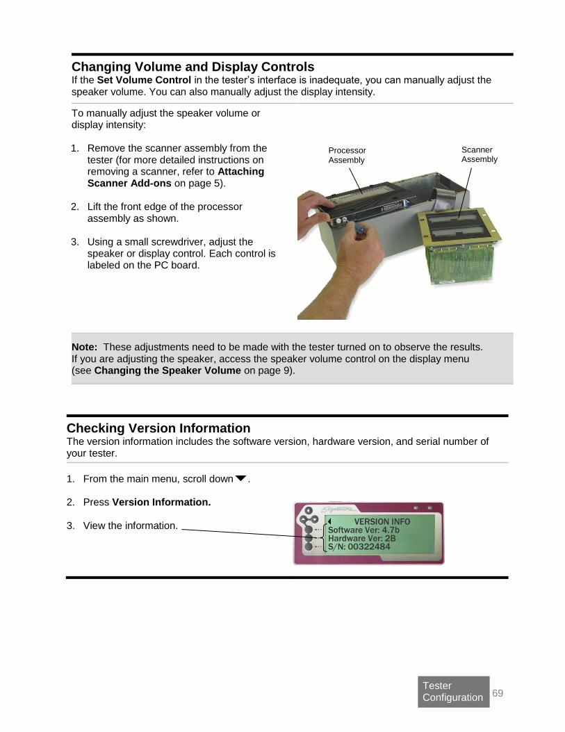
69 Tester Configuration
Changing Volume and Display Controls If the Set Volume Control in the tester’s interface is inadequate, you can manually adjust the speaker volume. You can also manually adjust the display intensity.
To manually adjust the speaker volume or display intensity: 1. Remove the scanner assembly from the
tester (for more detailed instructions on removing a scanner, refer to Attaching Scanner Add-ons on page 5).
2. Lift the front edge of the processor assembly as shown.
3. Using a small screwdriver, adjust the speaker or display control. Each control is labeled on the PC board.
Note: These adjustments need to be made with the tester turned on to observe the results. If you are adjusting the speaker, access the speaker volume control on the display menu (see Changing the Speaker Volume on page 9).
Checking Version Information The version information includes the software version, hardware version, and serial number of your tester.
1. From the main menu, scroll down .
2. Press Version Information.
3. View the information.
Scanner Assembly
Processor Assembly
VERSION INFO Software Ver: 4.7b Hardware Ver: 2B S/N: 00322484

70 General Information
Software Installation Guide
Requirements for a Station or Network Server
• 2.0 GHz min. processor speed
• Windows 7® or later
• 15 GB hard drive space
• 4 GB RAM
• 256 MB min. video memory
• 1024 x 768 min display resolution
• Sound (for audible feedback)
• USB 2.0 or 3.0 port
• Internet connection: Not required, but if available, can facilitate support issues. For assistance:
• Call Cirris toll-free at 1-800-441-9910 or email [email protected]. • Outside the US, contact the Cirris office nearest you.
Updating a Previous Installation
IMPORTANT! Back up your database before you update your Cirris software installation.
Depending on the software version that is currently installed, you may need to perform special steps before installing the current version.
• If your previously installed software version is older than 2008.2.0, you must remove the previous version and store its data files before you install the new version.
• If your previously installed software version is 2008.2.0 or newer, proceed with the instructions below.
Note: If you are unsure of the previously installed version number, start your easy-wire software and check the version information (located on the right side of the easy-wire main menu) before proceeding.
Installing easy-wire Software and Cirris Server Software There may be driver conflicts between your tester and Windows. We therefore advise you to install the software before attaching the tester. 1. Install Cirris Server Software on the server by downloading Cirris Server Software from cirrris.com and
following the installation steps as they appear on screen. This will allow networking on all easy-wire stations.
2. Install easy-wire on each of the client PCs in the same manner by downloading easy-wire from
cirris.com and following the installation steps as they appear on screen.
Starting the Software 1. Double-click the easy-wire software icon to start the software.

71 General Information
2. Make sure you select the appropriate tester type in the User Login window.
Note: If you’ve updated an existing installation, the user name and password will be the same. 3. The main menu will display. If you have updated an existing installation, the software should allow you to
access your previous data.
Updating the Server Configuration Share the Cirris folder with those who have read/write permissions. Default folder location: C:\Users\Public\Public Documents\Cirris.
(1100) easy-wire PC Control for Benchtop Testers If you purchased your 1100 tester with easy-wire software, your tester will already be enabled to interface with your PC. If you purchased your 1100 tester without easy-wire and have since purchased the PC Control feature, follow these steps: 1. Install the easy-wire software on a PC.
2. Connect your tester to the PC.
3. Launch easy-wire Software. In the easy-wire main menu, click Utilities, Setup System Options, Enable
Features.
4. Follow the prompts in the “Features Available on this Tester” window.
1) Contact Cirris and provide the given serial number.
2) Enter the Feature Key that Cirris will have provided to you.
Press Install the Feature.
(CR, CH2) Attaching to a Network Database Server
1. On each station that will be attached to your network, click the Windows Start button.
2. Click on All Programs, Cirris Systems Corporation, [Installed Software], Attach Station to Network.
3. When the “Convert Stand Alone Station to Network Server” window appears, click Find Server Location to locate the database configuration file. This file will be located on the Network Database Server with the following default path: C:\Users\Public\Documents\Cirris\common\CirrisDataAccessServer.ini.
4. Click Convert.
72 General Information
General Information
Calibration Each new 1100R+ comes with a complimentary certificate of calibration. Cirris recommends that the tester be recalibrated on a one-year interval. For customers in the USA, Cirris offers complete calibration services in compliance with ANSI/NCSL Z540-1-1994 and MIL-STD 45662A. To verify calibration and functionality, you can purchase the 1100R+ Performance Check Kit. The 1100R+ Performance Check Kit has a valid calibration period of 2 years, after which it must be replaced. In addition to the performance check kit, you need a calibrated volt meter and high voltage probe capable of measuring the highest voltage the tester can output.
Note: In the event a Cirris tester is found to be out of calibration, there are no adjustable controls. The tester, or the affected portions, must be sent back to a Cirris facility for repair.
Adapters and Fixturing The contacts on Cirris adapters, or other fixturing that mate to the device-under-test, may wear due to repeated insertion cycles. Contact wear can result in higher connection resistances, which increases the measured resistances for the tested device. For this reason Cirris recommends customers evaluate the number of mating cycles and the cycle life of fixture contacts to determine maintenance intervals for testing and/or replacing fixturing contacts. A good way to check fixture contact resistance is to build and use a shorting block. For information on creating shorting blocks, see http://www.cirris.com/adapters/test-adapt.html.
Service All Cirris testers are designed as modules for easy servicing. Should your Cirris tester require service—as directed by Cirris support personnel—you may need to send the affected module or the entire tester back to Cirris for repair. During the repair period, a loaner tester can be sent to you if needed. You should not attempt to service any circuit board at the component level. All component-level service should be performed by Cirris technicians.
Conditions for Operation Your 1100R+ tester is intended to be used indoors at a temperature of 10°C (50°F) to 40°C (104°F). Best performance can be obtained at a relative humidity less than 75%. Insulation Resistance Measurements will degrade over 75% relative humidity. The unit can be mounted in a ventilated compartment. Be sure not to block the vents on the back of the tester. The unit can be mounted in a ventilated compartment. Never apply live voltages to the test points or probe input of your Cirris tester. Power supplies and other accessories not approved by Cirris may cause damage or present a hazard. If you use a Cirris product in a manner not specified in this manual and the accompanying help system, the protection provided by the product may be impaired.

73 Appendix
Appendix
Specifications
Test Point Capacity 128 to 1024 test points expandable in 128 point increments
Test Voltage Levels ≤ 5VDC 6mA maximum
Connection Resistance Sensitivity
0.1 – 100 K (± 1%)
Also: 500K, 1M, 5M (± 10%)
LV Insulation Resistance
0.1 - 100K (± 1%)
Also: 500K 1 M, 5 M (± 10%)
Test rate (typical) 128 test points in .25 seconds
Usable humidity range Relative humidity above 75% may adversely affect test
Component Specifications
Resistor: Learn 0.1 to 100 K ± 1%; Test 0.1 to 1M
Capacitor: Learn 5nF to 100 F ± 10%; Test 5nF to 100F ±
10% ± 20pF (relative measurements to 10 pF) Diode: Learn silicon diodes, zeners; Test silicon diodes, zeners and LEDs
Four-Wire Kelvin Resistance
0.005 to 10 (± 2%) ± 0.005. Current: 1A to 1.2; 0.25A to
10; <7mA above 10
I/O Port 4 inputs (0-24 VDC); 6 User programmable outputs (Sink: 24 VDC, 500mA max); Source Voltages: +5VDC 100mA, +10VDC 100mA.
Parallel Port Standard Epson/Centronics-type parallel interface
Memory Nonvolatile storage of up to 99 test programs
Power 100-250 VAC, 47-63 Hz, maximum 50 Watts
Dimensions and weight Main unit: 14.25” wide x 6.75” deep x 2.4” high (36.2cm wide x 17.2cm deep x 13.4cm high) Weight 9.7 pounds (4.4 kilograms)
Scanner Add-on: 6.25” wide x 6.75” deep x 2.4” high (15.9cm wide x 13.4cm deep x 13.4cm high), weight: 6.3 pounds (2.8 kilograms)

74 Appendix
Warranty
Cirris Systems Corporation warrants the Signature 1100R+ Cable Analyzer to be free of defects in materials or workmanship for a period of one (1) year from the date of delivery to you, as evidenced by receipt of your warranty registration form. In the event a defect develops due to normal use during the warranty period, Cirris Systems Corporation will repair or replace the analyzer with a new or reconditioned unit of equal value. In the event of replacement with a new or reconditioned model, the replacement unit will continue the warranty period of the original analyzer. The replacement unit will generally ship within one working day for customers in the USA. If the analyzer failure results from accident, abuse, or misapplication, Cirris Systems Corporation shall have no responsibility to replace the analyzer or refund the purchase price. Defects arising from such causes will be considered a breach of this warranty. Cirris Systems Corporation is not responsible for special, incidental, or consequential damages resulting from any breach of warranty, or under any other legal theory, including lost profits, downtime, goodwill, damage to or replacement of equipment and property, and any costs of recovering materials used with the Signature 1100R+ Cable Analyzer. ANY IMPLIED WARRANTIES ARISING OUT OF SALES OF THE SIGNATURE 1100R+ CABLE ANALYZER, INCLUDING BUT NOT LIMITED TO IMPLIED WARRANTIES OF MERCHANTABILITY AND FITNESS FOR A PARTICULAR PURPOSE ARE LIMITED IN DURATION TO THE ABOVE STATED ONE (1) YEAR PERIOD. CIRRIS SYSTEMS CORPORATION SHALL NOT BE LIABLE FOR INCIDENTAL OR CONSEQUENTIAL DAMAGE, EXPENSES, OR ECONOMIC LOSS. Some states do not allow limitations on length of implied warranty or the exclusion or limitation of incidental or consequential damages, therefore the above limitations and exclusions may not apply to you. This warranty gives you specific legal rights. You may also have other legal rights, which vary from state to state. Cirris Systems Corporation Salt Lake City, Utah PURCHASE DATE: ____________________ SERIAL NUMBER: _______________________
1100R+ Warranty
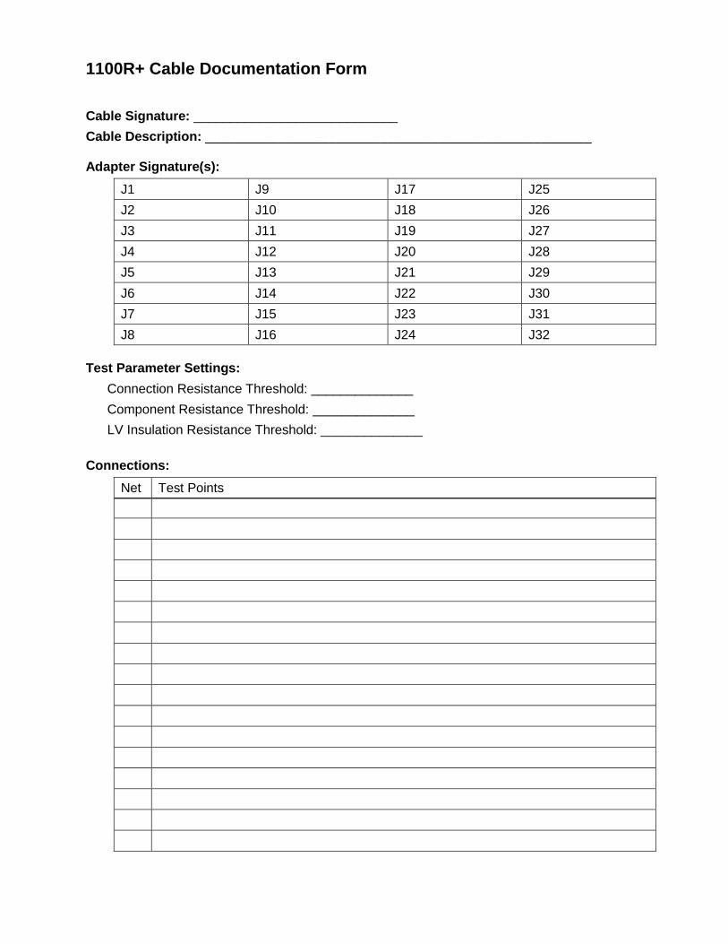
1100R+ Cable Documentation Form Cable Signature: ____________________________
Cable Description: _____________________________________________________ Adapter Signature(s):
J1 J9 J17 J25
J2 J10 J18 J26
J3 J11 J19 J27
J4 J12 J20 J28
J5 J13 J21 J29
J6 J14 J22 J30
J7 J15 J23 J31
J8 J16 J24 J32
Test Parameter Settings:
Connection Resistance Threshold: ______________
Component Resistance Threshold: ______________
LV Insulation Resistance Threshold: ______________
Connections:
Net Test Points

Connections continued:
Net Test Points
Components:

Notes:

1100R+ Test Program Location Listing Unit Serial Number: ______________________
Drive Folder Mem. Loc.
Part Number
Cable Description
Cable Signature/ File Name
Index
A
Adapter double-high · 11 installing · 12 quad-high · 11 setup · 14 Signatures · 16 single-high · 11 sizes · 11
Adapters Checking · 69
Auto Start Test · 36
B
Bad component error · 54 Bad LED · 50, 8
C
Cable error messages · 1–57 component · 54 error tones · 50 intermittent · 53 low voltage · 51–53 viewing · 50
Cable Signatures · 15 Calculating connection resistance · 41 Calibration · 69 Capacitors, testing · 43, 44 Component
default values · 29 errors · 54 Resistance Setting · 43 test values · 30 testing · 44
Conditions for Operation · 69 Connection Signature · 15 Continuous Test Mode · 35 Contrast · See Display adjustment CTLWIN
examples · 30 installing · 29 uses · 29
Customer Support · 1
D
Default Point Labels · 29 Digital I/O · 55 Display adjustment · 68 Documenting
Cable Documentation Form · 72–74 Memory Location Listing · 75
Download Utility · 61
E
Editing Test Parameter Settings · 40 Error messages · See Cable error messages Error Tones · 50 External Switch · 35
F
Factory Defaults · 33 Fault Location · 36 Fixturing
Checking · 69 Folders · 23, 24 Four-Wire Testing · 46
buiding fixturing · 46 Kelvin Points · 48 learning test · 49 point types · 46 probing point types · 49 turning on · 49
G
Good LED · 8
H
Hardware version · 68 High resistance errors · 53
I
I/O Port · 55 Intermittent errors · 53
L
Labels · 2 · See Scripting manual · 40-42 Leaky diode error · 54 Learn and Test Settings · 39–49
changing · 39 Component Resistance · 43 learn · 32 Learn Component · 44 LV Insulation Resistance · 42 restoring factory defaults · 33 Test Parameter · 32
Learn Component Setting · 44 LEDs · See Components, testing Links · 29, 30, 45 Loaded test · 16 Low voltage errors · 51–53 LV Insulation Resistance Setting · 42
M
Memory deleting · 27 deleting from · 26 external · 16 internal · 16 loading from · 26 saving to · 25
Missing component error · 54 Missing diode error · 54 Miswire errors · 52
N
Nets · 14 Networking · 2
O
Open error · 52 Outputs
example circuits · 57–59 setting up · 60
P
Parameter Signature · See Test Parameter Signature Pins · 14 Point Labels · 29 Preferences · See User Preferences Printer · 4 Printing
cable documentation · 19 errors · 50 labels (see Scripting manual, p. 40-42) · 2 test reports · 37 test summaries · 22
Probe installing · 3 using · 22
R
Reports · 18, 19, 37
S
Saving test programs · 25 Scanner Add-ons
attaching · 5–7 labeling · 7
Scripting · 2, 56 Serial Number · 68 Service · 69 Short error · 51 shorting blocks · 69 Shottky diodes · See Components, testing Signatures
Adapter · 16 Cable · 15 Connection · 15 Test Parameter · 15
Single Test Mode · 35 Software version · 68 Software Version · 61 SPC Data Collection · 66 Speaker Volume · See Volume Control Specifications · 70
T
Test Mode · 35 Test Parameter Settings · 32 Test Parameter Signature · 15 Test Program Location Listing · 27, 28, 75 Test programs
creating · 17 documenting · 18, 19
Test summary · 22 Testing · 20, 33 Thumb drive · 3, 16, 23
U
User Preferences · 32 Auto Start Test · 36 External Switch · 35 Fault Location · 36 restoring factory defaults · 33 Test Mode · 35
V
Version information · 68 Volume control
manual adjustment · 68 User Preference · 9
W
Warranty · 71
Z
Zener diodes · See Components, testing

Signature 1100R+ User Manual
Version 2017.2.0
© 2016 Cirris Systems Corporation
401 North 5600 West Salt Lake City, UT 84116
USA www.cirris.com