11/11/04© university of wisconsin, cs559 fall 2004 last time shading interpolation texture mapping...
TRANSCRIPT
11/11/04 © University of Wisconsin, CS559 Fall 2004
Last Time
• Shading Interpolation
• Texture mapping– Barycentric coordinates for triangles

11/11/04 © University of Wisconsin, CS559 Fall 2004
Today
• Texture Anti-Aliasing
• Texture boundaries
• Modeling introduction

11/11/04 © University of Wisconsin, CS559 Fall 2004
Texture Recap
• We must reconstruct the texture image at the point (s,t)
• Time to apply the theory of sampling and reconstruction
Triangle in 8x8 Texture Map, I(s,t)
s
t
Triangle in world space
Interpolated (s,t) – we need a texture sample from I(s,t)
I(s,t)

11/11/04 © University of Wisconsin, CS559 Fall 2004
Textures and Aliasing
• Textures are subject to aliasing:– A polygon pixel maps into a texture image, essentially sampling the
texture at a point
– The situation is essentially an image warp, with the warp defined by the mapping and projection
• Standard approaches:– Pre-filtering: Filter the texture down before applying it
• Useful when the texture has multiple texels per output image pixel
– Post-filtering: Take multiple pixels from the texture and filter them before applying to the polygon fragment
• Useful in all situations

11/11/04 © University of Wisconsin, CS559 Fall 2004
Point Sampled Texture Aliasing
• Note that the back row is a very poor representation of the true image
Texture map
Polygon far from the viewer in perspective projection
Rasterized and textured
11/11/04 © University of Wisconsin, CS559 Fall 2004
Mipmapping (Pre-filtering)
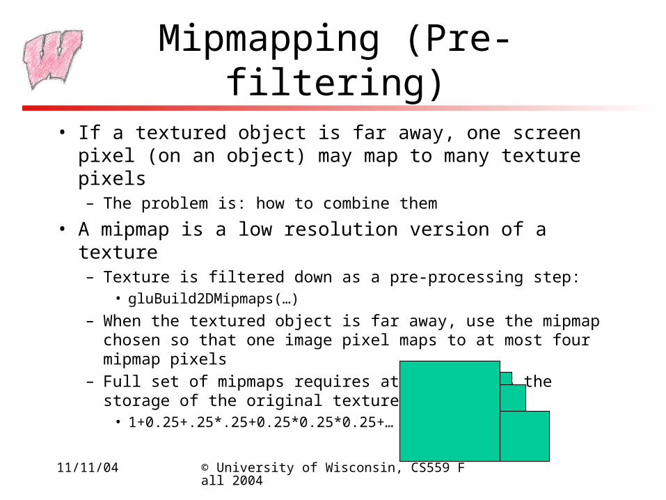
• If a textured object is far away, one screen pixel (on an object) may map to many texture pixels– The problem is: how to combine them
• A mipmap is a low resolution version of a texture– Texture is filtered down as a pre-processing step:
• gluBuild2DMipmaps(…)
– When the textured object is far away, use the mipmap chosen so that one image pixel maps to at most four mipmap pixels
– Full set of mipmaps requires at most 1.3333 the storage of the original texture (in the limit)
• 1+0.25+.25*.25+0.25*0.25*0.25+…

11/11/04 © University of Wisconsin, CS559 Fall 2004
Many Texels for Each Pixel
Texture map with pixels drawn on it.Some pixels cover many texture elements (texels)
Polygon far from the viewer in perspective projection
11/11/04 © University of Wisconsin, CS559 Fall 2004
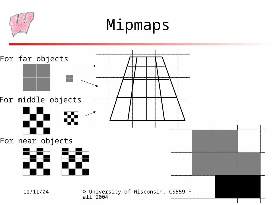
Mipmaps
For near objects
For far objects
For middle objects

11/11/04 © University of Wisconsin, CS559 Fall 2004
Mipmap Math
• Define a scale factor, =texels/pixel– A texel is a pixel from a texture is actually the maximum from x and y
– The scale factor may vary over a polygon
– It can be derived from the transformation matrices
• Define =log2 tells you which mipmap level to use
– Level 0 is the original texture, level 1 is the next smallest texture, and so on
– If <0, then multiple pixels map to one texel: magnification
11/11/04 © University of Wisconsin, CS559 Fall 2004
Post-Filtering
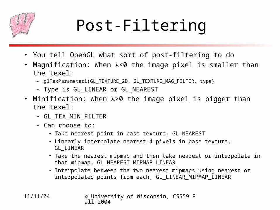
• You tell OpenGL what sort of post-filtering to do
• Magnification: When <0 the image pixel is smaller than the texel:– glTexParameteri(GL_TEXTURE_2D, GL_TEXTURE_MAG_FILTER, type)
– Type is GL_LINEAR or GL_NEAREST
• Minification: When >0 the image pixel is bigger than the texel:– GL_TEX_MIN_FILTER– Can choose to:
• Take nearest point in base texture, GL_NEAREST• Linearly interpolate nearest 4 pixels in base texture, GL_LINEAR• Take the nearest mipmap and then take nearest or interpolate in that mipmap, GL_NEAREST_MIPMAP_LINEAR
• Interpolate between the two nearest mipmaps using nearest or interpolated points from each, GL_LINEAR_MIPMAP_LINEAR

11/11/04 © University of Wisconsin, CS559 Fall 2004
Filtering Example
Level 0
Level 2
Level 1
s=0.12,t=0.1=1.4=0.49
NEAREST_MIPMAP_NEAREST:level 0, pixel (0,0)
LINEAR_MIPMAP_NEAREST:level 0, pixel (0,0) * 0.51+ level 1, pixel (0,0) * 0.49
NEAREST_MIPMAP_LINEAR:level 0, combination ofpixels (0,0), (1,0), (1,1), (0,1)
LINEAR_MIPMAP_LINEAR:Combination of level 0 and level 1, 4 pixels from each level, using 8 pixels in all

11/11/04 © University of Wisconsin, CS559 Fall 2004
Boundaries
• You can control what happens if a point maps to a texture coordinate outside of the texture image– All texture images are assumed to go from (0,0) to (1,1) in texture
space – means that the mapping is independent of the texture size– The problem is how to extend the image to make an infinite space
• Repeat: Assume the texture is tiled– glTexParameteri(GL_TEXTURE_2D, GL_TEXTURE_WRAP_S, GL_REPEAT)
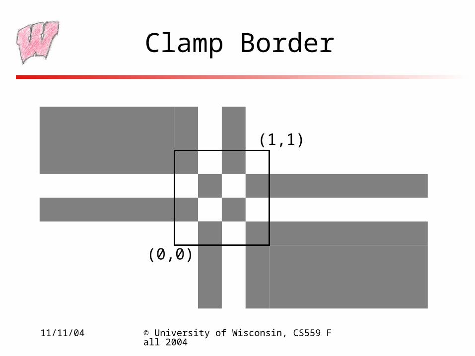
• Clamp to Edge: the texture coordinates are truncated to valid values, and then used
– glTexParameteri(GL_TEXTURE_2D, GL_TEXTURE_WRAP_S, GL_CLAMP)
• Can specify a special border color:– glTexParameterfv(GL_TEXTURE_2D, GL_TEXTURE_BORDER_COLOR, R,G,B,A)

11/11/04 © University of Wisconsin, CS559 Fall 2004
Repeat Border
(0,0)
(1,1)
11/11/04 © University of Wisconsin, CS559 Fall 2004
Clamp Border
(0,0)
(1,1)

11/11/04 © University of Wisconsin, CS559 Fall 2004
Border Color
(0,0)
(1,1)

11/11/04 © University of Wisconsin, CS559 Fall 2004
Other Texture Stuff
• Texture must be in fast memory - it is accessed for every pixel drawn– If you exceed it, performance will degrade horribly– Skilled artists can pack textures for different objects into one
image
• Texture memory is typically limited, so a range of functions are available to manage it
• Specifying texture coordinates can be annoying, so there are functions to automate it
• Sometimes you want to apply multiple textures to the same point: Multitexturing is now in most new hardware

11/11/04 © University of Wisconsin, CS559 Fall 2004
Yet More Texture Stuff
• There is a texture matrix: apply a matrix transformation to texture coordinates before indexing texture
• There are “image processing” operations that can be applied to the pixels coming out of the texture
• There are 1D and 3D textures– Mapping works essentially the same
– 3D textures are very memory intensive, and how they are used is very application dependent
– 1D saves memory if the texture is inherently 1D, like stripes

11/11/04 © University of Wisconsin, CS559 Fall 2004
Procedural Texture Mapping
• Instead of looking up an image, pass the texture coordinates to a function that computes the texture value on the fly– Renderman, the Pixar rendering language, does this
– Available in a limited form with fragment shaders on current generation hardware
• Advantages:– Near-infinite resolution with small storage cost
– Idea works for many other things
• Has the disadvantage of being slow in most cases

11/11/04 © University of Wisconsin, CS559 Fall 2004
Other Types of Mapping
• Environment mapping looks up incoming illumination in a map– Simulates reflections from shiny surfaces
• Bump-mapping computes an offset to the normal vector at each rendered pixel– No need to put bumps in geometry, but silhouette looks wrong
• Displacement mapping adds an offset to the surface at each point– Like putting bumps on geometry, but simpler to model
• All are available in software renderers like RenderMan compliant renderers
• All these are becoming available in hardware

11/11/04 © University of Wisconsin, CS559 Fall 2004
The Story So Far
• We’ve looked at images and image manipulation
• We’ve looked at rendering from polygons
• Next major section:– Modeling

11/11/04 © University of Wisconsin, CS559 Fall 2004
Modeling Overview
• Modeling is the process of describing an object
• Sometimes the description is an end in itself– eg: Computer aided design (CAD), Computer Aided Manufacturing
(CAM)
– The model is an exact description
• More typically in graphics, the model is then used for rendering (we will work on this assumption)– The model only exists to produce a picture
– It can be an approximation, as long as the visual result is good
• The computer graphics motto: “If it looks right it is right”– Doesn’t work for CAD

11/11/04 © University of Wisconsin, CS559 Fall 2004
Issues in Modeling
• There are many ways to represent the shape of an object
• What are some things to think about when choosing a representation?

11/11/04 © University of Wisconsin, CS559 Fall 2004
Choosing a Representation
• How well does it represents the objects of interest?
• How easy is it to render (or convert to polygons)?
• How compact is it (how cheap to store and transmit)?
• How easy is it to create?– By hand, procedurally, by fitting to measurements, …
• How easy is it to interact with?– Modifying it, animating it
• How easy is it to perform geometric computations?– Distance, intersection, normal vectors, curvature, …

11/11/04 © University of Wisconsin, CS559 Fall 2004
Categorizing Modeling Techniques
• Surface vs. Volume– Sometimes we only care about the surface
• Rendering and geometric computations
– Sometimes we want to know about the volume• Medical data with information attached to the space• Some representations are best thought of defining the space filled,
rather than the surface around the space
• Parametric vs. Implicit– Parametric generates all the points on a surface (volume) by
“plugging in a parameter” eg (sin cos, sin sin, cos)– Implicit models tell you if a point in on (in) the surface (volume) eg
x2 + y2 + z2- 1 = 0
11/11/04 © University of Wisconsin, CS559 Fall 2004
Parameterization
• Parameterization is the process of associating a set of parameters with every point on an object– For instance, a line is easily parameterized by a single value
• Actually, the barycentric parameterization for a line
– Triangles can be parameterized by their barycentric coordinates
– Polygons can be parameterized by defining a 2D space in the plane of the polygon, and using the 2D coordinates to give you 3D
• Several properties of a parameterization are important:– The smoothness of the mapping from parameter space to 3D points
– The ease with which the parameter mapping can be inverted
– Many more
• We care about parameterizations for several reasons– Texture mapping is the most obvious one you have seen so far

11/11/04 © University of Wisconsin, CS559 Fall 2004
Techniques We Will Examine
• Polygon meshes– Surface representation, Parametric representation
• Prototype instancing and hierarchical modeling– Surface or Volume, Parametric
• Volume enumeration schemes– Volume, Parametric or Implicit
• Parametric curves and surfaces– Surface, Parametric
• Subdivision curves and surfaces
• Procedural models