112 general information - helmacab.nl · iec 60092-352 0,6/1 kv +90°c marine cables. if a cable is...
TRANSCRIPT

112
10/2017
Halogen-free refers to the absence of halogens, such as chlorine and fluorine, and is determined on the basis of halogen content and the acidity of gases of a cable. IEC 60754-1 determines the halogen content of the material. To meet the requirements as halogen-free the halogen content of the material may not exceed 0,5 % or 5 mg/g. IEC 60754-2 determines the degree of acidity of gases evolved during combustion. The limit values are 4,3 for pH and 10 mikroS for conductivity.
Standard for materials: IEC 60092-360
Insulation material:The following designations are used for insulation materials in this catalog. All materials are halogen-free.XLPE stands for cross-linked polyethylene compound. It has excellent mechanical and electrical characteristics.
Sheathing material:The designation SHF1 stands for thermo-plastic compound. This material is halogen-free, highly flame-retardant and has low smoke emission.The designation SHF2 stands for oil resistant thermosetting compound. This material is halogen-free, highly flame-retardant and has low smoke emission.
Definition of terms:Oil resistanceSheathing material is oil resistant according to method IEC 60811-404 and requirements from IEC 60092-360/SHF2. The oil resistance is demonstrated by immersion in IRM902 oil for 24h at 100°C.
Flame-retardant To be flame-retardant, the cables must withstand the test specified in IEC standard 60332-3 or IEC 60332-1. Flame-retardant cables do not propagate fire, and are self-extinguishing.
Test on bunched cables IEC 60332-3Burning is allowed up to max. 2.5 meters from the burner within specified time.
IEC 60332-1 is the test for single insulated wire and cable. Test procedure and require-ments according to the picture below.
Min. 50 mm of the cable, measured from the upper support, must remain unburned after the specified time.
Fire-resistantIEC 60331-1 Test method for fire with shock at a temperature of at least 830 °C for 90 minutes for cables of rated voltage up to and including 0,6/1,0 kV and with an overall diameter exceeding 20 mm.
IEC 60331-2 Test method for fire with shock at a temperature of at least 830 °C for 90 minutes for cables of rated voltage up to and including 0,6/1,0 kV and with an overall diameter not exceeding 20 mm.
Smoke emission refers to visibility in a fire. The greater the light trans-mittance, the better the visibility. When tested in accordance with IEC 61034-1 (test method) and IEC 61034-2 (test requirements) the smoke emission of a cable during fire must not exceed the following values.
27m3 cube smoke chamber
Requirements: 60 % lighttransmittance
IEC 60332-3-22 is the test for bunched cables. Burning time describes how long the burner is directed towards the bunch of cables. The requirement for passing the test is that after the burner has been removed the cables must extinguish themselves. Burning may not occur more than 2.5 m from the burner as shown in the figure.
All Helkama cables comply with the most severe requirements of category A. Amount of burning material is 7 litres/m and burning time 40 minutes.
50 mm
475 550 600 mm mm mm
830 °C / 90 min
Un 3A
110 mm
gas burner 500 mm
General information

113
10/2017
Recommended minimum bending radius, (R):
Radius (R)
Outer diameter
(D)
LKM-HF During installation R = 6x D < 25mmLKMM-HF During installation R = 9x D > 25mmLKEM-HF Fixed installation R = 4x D < 25mm Fixed installation R = 6x D > 25mm
During installation R = 9x D Fixed installation R = 6x D
RFE-HFRFE-HF(i)RFA-HFRFA-HF(i)RFE-FRHFRFE-FRHF(i)RFA-FRHFRFA-FRHF(i)LKSM-SHF2 120°CLKSM-SHF2 120°CRFE-SHF2 120°CRFE-SHF2 (i) 120°C
LKSM-HFLKSM-EMCRFE-EMC-FRHF RFE-EMC-FRHF(i)LKSM-VFDLKMSM-HFLKAM-HFLKM-FRHFLKMM-FRHFLKSM-FRHFLKMSM-FRHFLKAM-FRHF
BENDING RADIUS
DIAMETER TOLERANCE
Cable outer diameter, mm. Tolerance 1 – 10 ±0,5mm 10,1 – 20 ±1,0mm 20,1 – 30 ±1,5mm
Cable outer diameter, mm. Tolerance30,1 – 40 ±2,0mm 40,1 – 50 ±2,5mm 50,1 – 60 ±3,0mm
(according to HD 308 S2)
0,6/1kV Normal type G-type (with earth conductor)
1-core
2-cores
3-cores
4-cores
5-cores
7-cores and above
BN BU
Black numbers on white base
Last core yellow/green.
Black numbers on white base
1,8/3kV LKSM-VFD
1-core
3-cores
3-cores + 3-ground cores
BU = Blue, BN = Brown, BK = Black, GY = Grey, Y/G = Yellow/Green
Sheath marking: Lot number, cable type, cable size, voltage, temperature, standards, manufacturer’s name, production month and meter marking printed on the sheath
CORE IDENTIFICATION
250V pair cables
Pair number a b2 3 43 5 64 7 85 9 10etc. Each pair white - blue. Cores numbered 1, 2, 3, 4, 5....
250V triple cables
Each triplewhite-blue-redCores numbered 1, 2, 3, 4, 5....
250V quad cables
(Quad)cable is built up as a star quad with the following identification1 core white2 core blue3 core white4 core blue
134
2
250V multicore cables
2-cores Black numbers on white base
3-cores Black numbers on white base
4-cores Black numbers to 37-cores on white base
1 2
1 23
114
10/2017
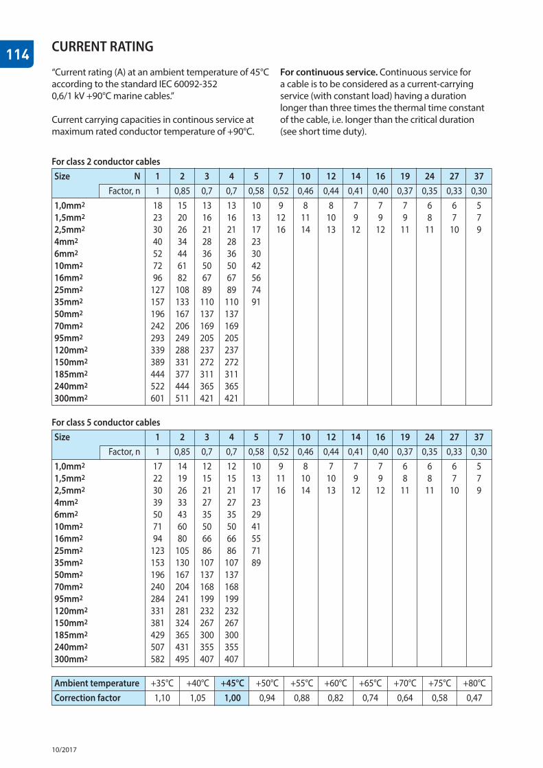
“Current rating (A) at an ambient temperature of 45°C according to the standard IEC 60092-352 0,6/1 kV +90°C marine cables.”
Current carrying capacities in continous service at maximum rated conductor temperature of +90°C.
CURRENT RATING
For continuous service. Continuous service for a cable is to be considered as a current-carrying service (with constant load) having a duration longer than three times the thermal time constant of the cable, i.e. longer than the critical duration (see short time duty).
For class 2 conductor cablesSize N 1 2 3 4 5 7 10 12 14 16 19 24 27 37 Factor, n 1 0,85 0,7 0,7 0,58 0,52 0,46 0,44 0,41 0,40 0,37 0,35 0,33 0,301,0mm2 18 15 13 13 10 9 8 8 7 7 7 6 6 51,5mm2 23 20 16 16 13 12 11 10 9 9 9 8 7 72,5mm2 30 26 21 21 17 16 14 13 12 12 11 11 10 94mm2 40 34 28 28 23 6mm2 52 44 36 36 30 10mm2 72 61 50 50 42 16mm2 96 82 67 67 56 25mm2 127 108 89 89 74 35mm2 157 133 110 110 91 50mm2 196 167 137 137 70mm2 242 206 169 169 95mm2 293 249 205 205 120mm2 339 288 237 237 150mm2 389 331 272 272 185mm2 444 377 311 311 240mm2 522 444 365 365 300mm2 601 511 421 421
For class 5 conductor cablesSize 1 2 3 4 5 7 10 12 14 16 19 24 27 37
Factor, n 1 0,85 0,7 0,7 0,58 0,52 0,46 0,44 0,41 0,40 0,37 0,35 0,33 0,301,0mm2 17 14 12 12 10 9 8 7 7 7 6 6 6 51,5mm2 22 19 15 15 13 11 10 10 9 9 8 8 7 72,5mm2 30 26 21 21 17 16 14 13 12 12 11 11 10 94mm2 39 33 27 27 23 6mm2 50 43 35 35 29 10mm2 71 60 50 50 41 16mm2 94 80 66 66 55 25mm2 123 105 86 86 71 35mm2 153 130 107 107 89 50mm2 196 167 137 137 70mm2 240 204 168 168 95mm2 284 241 199 199 120mm2 331 281 232 232 150mm2 381 324 267 267 185mm2 429 365 300 300 240mm2 507 431 355 355 300mm2 582 495 407 407
Ambient temperature +35°C +40°C +45°C +50°C +55°C +60°C +65°C +70°C +75°C +80°CCorrection factor 1,10 1,05 1,00 0,94 0,88 0,82 0,74 0,64 0,58 0,47

115
10/2017
SHORT CIRCUIT CURRENT
Maximum permissible short circuit current.0,6/1 kV +90°C marine cables.
Based on formula:
Ik = 226 X X In
Formula 1:
Ik = 146 X
Ik = Maximum permissible short circuit current. S = Cross-section of the conductor in mm2. t = Duration of the short circuit in s. Tk = Maximum rated conductor temperature, Tb = Maximum rated conductor temperature, normal, °C Formula 1: For 0,6/1kV cable with XLPE or HF90 with maximum operating temperature of +90°C (Tb) and short circuit temperature of +250°C (Tk).
St
St
234 + Tk234 + Tb
SHORT CIRCUIT FACTOR Short Circuit Factor can be calculated by following formula:
SHORT CIRCUIT FACTOR =SHORT CIRCUIT CURRENT
CURRENT RATING
Cross-section of Duration of the short circuit in s.the conductor in mm2 0,2 0,5 1 2 3 10 1,0 0,3 0,2 0,1 0,1 0,1 0,0 1,5 0,5 0,3 0,2 0,2 0,1 0,1 2,5 0,8 0,5 0,4 0,3 0,2 0,1 4 1,3 0,8 0,6 0,4 0,3 0,2 6 2,0 1,2 0,9 0,6 0,5 0,3 10 3,3 2,1 1,5 1,0 0,8 0,5 16 5,2 3,3 2,3 1,7 1,3 0,7 25 8,2 5,2 3,7 2,6 2,1 1,2 35 11,4 7,2 5,1 3,6 3,0 1,6 50 16,3 10,3 7,3 5,2 4,2 2,3 70 22,9 14,5 10,2 7,2 5,9 3,2 95 31,0 19,6 13,9 9,8 8,0 4,4 120 39,2 24,8 17,5 12,4 10,1 5,5 150 49,0 31,0 21,9 15,5 12,6 6,9 185 60,4 38,2 27,0 19,1 15,6 8,5 240 78,4 49,6 35,0 24,8 20,2 11,1 300 97,9 61,9 43,8 31,0 25,3 13,9 Short circuit current in kA
RATED VOLTAGESDesignating the of the rated voltages of cables are Uo/U (Um), where
Uo is the rated power-frequency voltage between phase conductor and earth ormetallic screen, for which the cable is designed.
U is the rated power-frequency voltage between phase conductors for which the cable is designed.
Um is the maximum value of the “highest system voltage” for which the cable may be used.
For DC voltages, maximum of 1,5 times the AC voltage. may be provided that thevoltage to earth does not exceed U0DC.
Cable AC DC voltage U0 U Um U U0DC
250V 150V 250V 300V 375V 250V 0,6/1kV 0,6kV 1,0kV 1,2kV 1,5kV 0,9kV 1,8/3kV 1,8kV 3,0kV 3,6kV – –

116
10/2017
SHORT TIME DUTY
INTERMITTENT SERVICE
Short time duty according to the standard IEC 60092-352 0,6/1 kV +90°C marine cables. If a cable is intended to supply motor or equipment operating for periods of half an hour or one hour, its current rating given in table “current rating”, may be increased using the relevant correction factors given by formula:
correction 1,12 factor 1-exp(-ts/T)
(ts = service time, min. T = Time constant, min.)
T = 0,245 x d 1,35 (d = Overall diameter of the cable, mm.)
Correction factor for intermittent service according to the standard IEC 60092-352
The correction factor given hereby has been roughly calculated for periods of 10 min, of which 4 min are with a constant load and 6 min without load.
Intermittence period = 10min.Intermittence ratio = 40%.
1-exp(-10/T) 1-exp(-4/T)
Overall Service Time Critical diameter of time, min. constant, duration, the cable, min. min. mm. 30 60 T 3x T 1 1,058 1,058 0,245 0,735 2 1,058 1,058 0,625 1,87 3 1,058 1,058 1,08 3,24 4 1,058 1,058 1,59 4,78 5 1,058 1,058 2,15 6,46 6 1,058 1,058 2,75 8,26 7 1,058 1,058 3,39 10,2 8 1,059 1,058 4,06 12,2 9 1,059 1,058 4,76 14,3 10 1,061 1,058 5,48 16,5 20 1,126 1,066 14,0 41,9 30 1,255 1,105 24,2 72,5 40 1,403 1,173 35,6 107 50 1,554 1,254 48,2 145 60 1,705 1,341 61,6 185 Correction factor.
Fi =
=
Overall diameter of Correction the cable, mm. factor. 1 1,000 2 1,001 3 1,012 4 1,042 5 1,083 6 1,127 7 1,170 8 1,208 9 1,242 10 1,273 20 1,433 30 1,490 40 1,518 50 1,534 60 1,544
117
10/2017
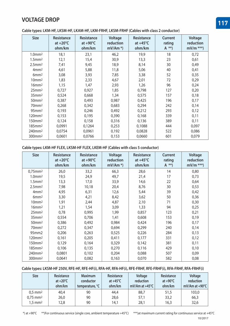
VOLTAGE DROP
Cable types: LKM-HF, LKSM-HF, LKAM-HF, LKM-FRHF, LKSM-FRHF (Cables with class 2 conductor)
Size Resistance Resistance Voltage Resistance Current Voltage at +20°C at +90°C reduction at +45°C rating reduction ohm/km ohm/km mV/Am *) ohm/km A **) mV/m ***) 1.0mm2 18,1 23,1 46,2 19,9 18 0,72 1.5mm2 12,1 15,4 30,9 13,3 23 0,61 2.5mm2 7,41 9,45 18,9 8,14 30 0,49 4mm2 4,61 5,88 11,8 5,06 40 0,41 6mm2 3,08 3,93 7,85 3,38 52 0,35 10mm2 1,83 2,33 4,67 2,01 72 0,29 16mm2 1,15 1,47 2,93 1,26 96 0,24 25mm2 0,727 0,927 1,85 0,798 127 0,20 35mm2 0,524 0,668 1,34 0,575 157 0,18 50mm2 0,387 0,493 0,987 0,425 196 0,17 70mm2 0,268 0,342 0,683 0,294 242 0,14 95mm2 0,193 0,246 0,492 0,212 293 0,12 120mm2 0,153 0,195 0,390 0,168 339 0,11 150mm2 0,124 0,158 0,316 0,136 389 0,11 185mm2 0,0991 0,1264 0,253 0,1088 444 0,097 240mm2 0,0754 0,0961 0,192 0,0828 522 0,086 300mm2 0,0601 0,0766 0,153 0,0660 601 0,079
Cable types: LKM-HF FLEX, LKSM-HF FLEX, LKEM-HF (Cables with class 5 conductor)
Size Resistance Resistance Voltage Resistance Current Voltage at +20°C at +90°C reduction at +45°C rating reduction ohm/km ohm/km mV/Am *) ohm/km A **) mV/m ***) 0,75mm2 26,0 33,2 66,3 28,6 14 0,80 1.0mm2 19,5 24,9 49,7 21,4 17 0,73 1.5mm2 13,3 17,0 33,9 14,6 22 0,64 2.5mm2 7,98 10,18 20,4 8,76 30 0,53 4mm2 4,95 6,31 12,6 5,44 39 0,42 6mm2 3,30 4,21 8,42 3,62 50 0,36 10mm2 1,91 2,44 4,87 2,10 71 0,30 16mm2 1,21 1,54 3,09 1,33 94 0,25 25mm2 0,78 0,995 1,99 0,857 123 0,21 35mm2 0,554 0,706 1,41 0,608 153 0,19 50mm2 0,386 0,492 0,984 0,424 196 0,17 70mm2 0,272 0,347 0,694 0,299 240 0,14 95mm2 0,206 0,263 0,525 0,226 284 0,13 120mm2 0,161 0,205 0,411 0,177 331 0,12 150mm2 0,129 0,164 0,329 0,142 381 0,11 185mm2 0,106 0,135 0,270 0,116 429 0,10 240mm2 0,0801 0,102 0,204 0,088 507 0,09 300mm2 0,0641 0,082 0,163 0,070 582 0,08
Cable types: LKSM-HF 250V, RFE-HF, RFE-HF(i), RFA-HF, RFA-HF(i), RFE-FRHF, RFE-FRHF(i), RFA-FRHF, RFA-FRHF(i)
Size Resistance Maximum Resistance Voltage Resistance Voltage at +20°C conductor at +45°C reduction at +90°C reduction ohm/km temperature, °C ohm/km mV/Am at +45°C ohm/km mV/Am at +90°C 0,5 mm2 40,4 90 44,4 88,7 51,5 103,0 0,75 mm2 26,0 90 28,6 57,1 33,2 66,3 1,5 mm2 12,8 90 14,1 28,1 16,3 32,6
*) at +90°C **) For continuous service (single core, ambient temperature +45°C) ***) at maximum current rating for continuous service at +45°C