1120 ieee transactions on very large scale ...web.eecs.umich.edu/~sadya/pubs/tvlsi2002_fixed.pdf1120...
TRANSCRIPT

1120 IEEE TRANSACTIONS ON VERY LARGE SCALE INTEGRATION (VLSI) SYSTEMS, VOL. 11, NO. 6, DECEMBER 2003
Fixed-Outline Floorplanning: EnablingHierarchical Design
Saurabh N. Adya, Member, IEEE, and Igor L. Markov, Member, IEEE
Abstract—Classical floorplanning minimizes a linear combina-tion of area and wirelength. When simulated annealing is used, e.g.,with the sequence pair representation, the typical choice of movesis fairly straightforward. In this paper, we study the fixed-outlinefloorplan formulation that is more relevant to hierarchical designstyle and is justified for very large ASICs and SoCs. We empir-ically show that instances of the fixed-outline floorplan problemare significantly harder than related instances of classical floor-plan problems. We suggest new objective functions to drive sim-ulated annealing and new types of moves that better guide localsearch in the new context. Wirelength improvements and optimiza-tion of aspect ratios of soft blocks are explicitly addressed by thesetechniques. Our proposed moves are based on the notion of floor-plan slack. The proposed slack computation can be implementedwith all existing algorithms to evaluate sequence pairs, of which weuse the simplest, yet semantically indistinguishable from the fastestreported [28]. A similar slack computation is possible with manyother floorplan representations. In all cases the computation timeapproximately doubles. Our empirical evaluation is based on a newfloorplanner implementation Parquet-1 that can operate in bothoutline-free and fixed-outline modes. We use Parquet-1 to floor-plan a design, with approximately 32000 cells, in 37 min using atop-down, hierarchical paradigm.
Index Terms—Floorplanning, hierachical design, physicaldesign, placement, VLSI CAD.
I. INTRODUCTION
WE DESCRIBE the classical floorplanning frameworkand compare it to a modern fixed-outline formulation.
A. Classical Outline-Free Floorplanning
A typical floorplanning formulation entails a collection ofblocks, which can represent circuit partitions in applications.Each block is characterized by area (typically fixed) and shape-type, e.g., fixed rectangle, rectangle with varying aspect ratio,an L-shape, a T-shape, or a more general rectilinear polygon, etc(such shapes may optimize layouts of special types of circuits,e.g., datapaths). A solution to such a problem, i.e., a floorplan,specifies a selection of block shapes and overlap-free place-ments of blocks. Depending on shape constraints, a floorplan-ning formulation can be discrete or continuous. For example, ifat least one block is allowed to assume any rectangular shapewith fixed area and aspect ratio in the interval (where
) the solution space is no longer finite or discrete. Multiple
Manuscript received May 31, 2002; revised March 28, 2003.The authors are with the Department of Electrical Engineering and Com-
puter Science, University of Michigan, Ann Arbor, MI 48104 USA (e-mail:[email protected]).
Digital Object Identifier 10.1109/TVLSI.2003.817546
Fig. 1. Example to show that area-minimal placements do not hold forminimum wirelength objectives. Blocks A and B, connected by 2-pin nets tofixed pins P1 and P2, respectively. The blocks touch in no optimal solution ifthe pins are sufficiently far from each other.
aspect ratios can be implied by an IP block available in severalshapes as well as by a hierarchical partitioning-driven designflow for ASICs [26], [13] where only the number of standardcells in a block (and thus the total area) is known in advance. Inmany cases, e.g., for row-based ASIC designs, there are onlyfinitely many allowed aspect ratios, but solution spaces con-taining a continuum are used none the less, primarily becauseexisting computational methods cannot handle such a large dis-crete solution space directly [13]. We point out that in the clas-sical floorplanning formulations, movable blocks tend to havefixed aspect ratios, but the overall floorplan is not constrained byan outline. While several recent works allow for variable blockaspect ratios, the more modern fixed-outline formulation (seeSection I-B) has not been addressed.
Objective functions not directly related to area typically in-volve a hypergraph that connects given blocks. While moreinvolved hypergraph-based objective functions have been pro-posed, the popularity of the half-perimeter wirelength (HPWL)function is due to its simplicity and relative accuracy, giventhat routes are not available. The HPWL objective became evenmore relevant [13] with the wide use of multilayer over-the-cellrouting in which more nets are routed with shortest paths.
A fundamental theorem for many floorplan representations,says that at least one area-minimal placement can be repre-sented [20]. This does not hold for objectives that include wire-length because none of the optimal solutions may be “packed”which implies that more nets can be routed with shortest paths.Fig. 1 shows a small example that area-minimal placements donot hold for minimum wirelength objectives. We also note thatlack of incremental move structures in a floorplan representa-tion is an important weakness of typical topological floorplan-ners. Thus wirelength has to be calculated from scratch aftereach floorplan evaluation. For designs with many of wires, cal-culating the wirelength from scratch after each move can slowdown the floorplanner considerably [1].
For the remaining part of this paper, we will be dealing withthe area and HPWL objectives only, but even this simplified set-ting implies multi-objective optimization. Mathematically, besttradeoffs are captured by the nondominated frontier (NDF), alsoknown as the Pareto front.
1063-8210/03$17.00 © 2003 IEEE
ADYA AND MARKOV: FIXED-OUTLINE FLOORPLANNING: ENABLING HIERARCHICAL DESIGN 1121
Definition: A solution of a multi-objective optimizationproblem belongs to the nondominated frontier if no othersolution improves upon one of the objective functions whilepreserving (or improving) other objective functions.1 Of thoseworks on abstract floorplanning that address both objectives,most minimize a linear combination [27], [23], [28] witharbitrarily chosen coefficients. By a simple corollary of thedefinition of NDF, this produces nondominated solutions, mostlikely different for different coefficients. Note, however, thatarea and wirelength have different dimensions. Given thatnet lengths have the same order of magnitude as the and
dimensions of the floorplan itself, areas tend to be severalorders of magnitude larger than wirelengths and path delays.One can take the square root of the area so that the the termsbecome of the same magnitude. However, even if one tries torelate the area of a region to its perimeter, that relation dependson the aspect ratio (the rectangle 1 100 has perimeter length202, and the rectangle 10 10 has perimeter length 40, eventhough both have area 100). Since aspect ratio changes inthe course of floorplanning, one cannot come up with a fixedcoefficient. Moreover, net length may be much larger than theperimeter because of the large number of nets. Here again,there is no fixed coefficient because the net length changesduring the course of floorplanning and it is difficult to predictoptimal net lengths (some nets may be very short and somemay be very long). The problem is exacerbated, because fordifferent designs, different coefficients may be required to findthe NDF. In our experiments, area terms dominated wirelengthterms unless highly problem-specific coefficients are used. Inother words, it is difficult to fully automate a floorplanner thatexplores nondominated solutions with respect to wirelength andarea objectives. The relationship between linear combinationobjectives and the Pareto curve (NDF) is studied in [12]. Itis shown that with a suitable choice of coefficients, any pointon the “lower convex hull” of the NDF can be found. Thissuggests a systematic method of modifying the coefficientsto probe the hull and also characterizes the limitations of thelinear combination approach.
To summarize, classical floorplan approaches entail difficultmulti-objective optimization and often rely on representationsthat may not capture any minimum wirelength solutions.
B. Modern Fixed-Outline Floorplanning
As pointed out in previous works [13], [4], some of fun-damental difficulties in classical floorplanning are gracefullyresolved in the context of modern ASIC design. Modern hier-archical ASIC design flows based on multilayer over-the-cellrouting naturally imply fixed-die placement and floorplanningrather than the variable-die style, associated with channelrouting, two layers of metal and feedthroughs. Each top-downstep of such a flow may start with a floorplan of prescribedaspect ratio, and with blocks of bounded (but not fixed) aspectratios. The objective is to minimize wirelength subject to: 1)the fixed floorplan outlines, and perhaps 2) zero whitespace.Floorplans with no whitespace are called “mosaic” by Hong
1The design of optimization heuristics can be viewed as a problem with atleast two objective functions—runtime and solution quality.
(a)
(b)
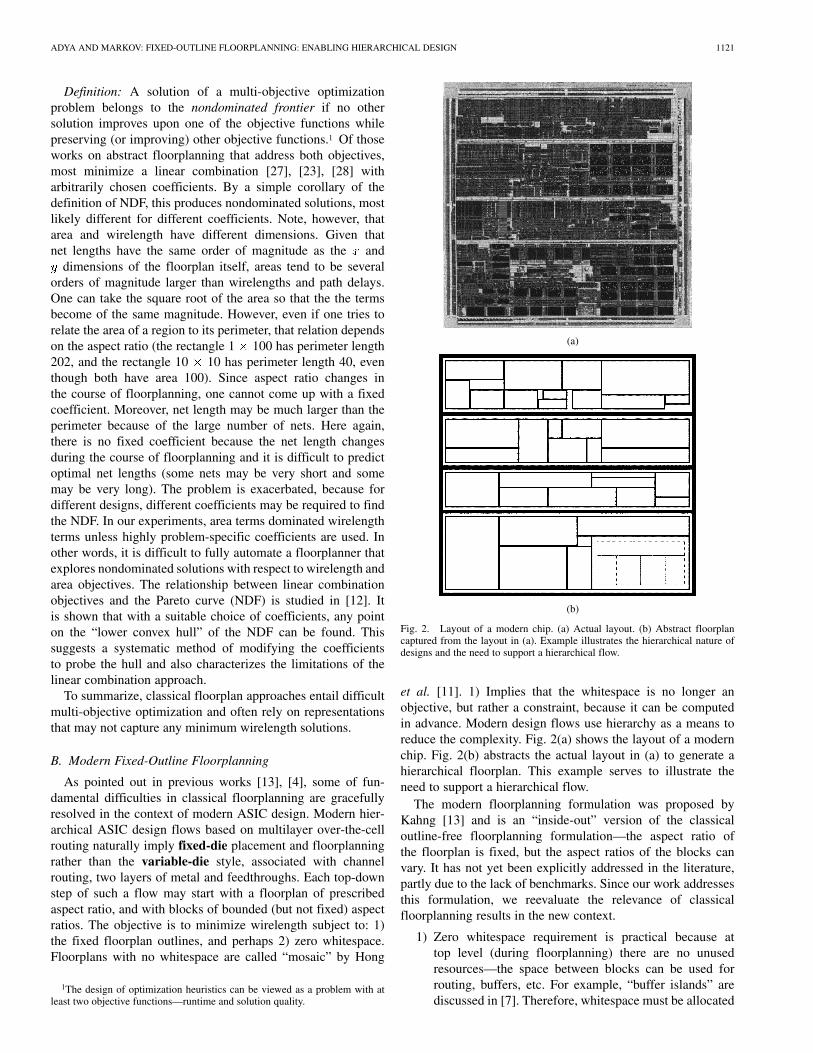
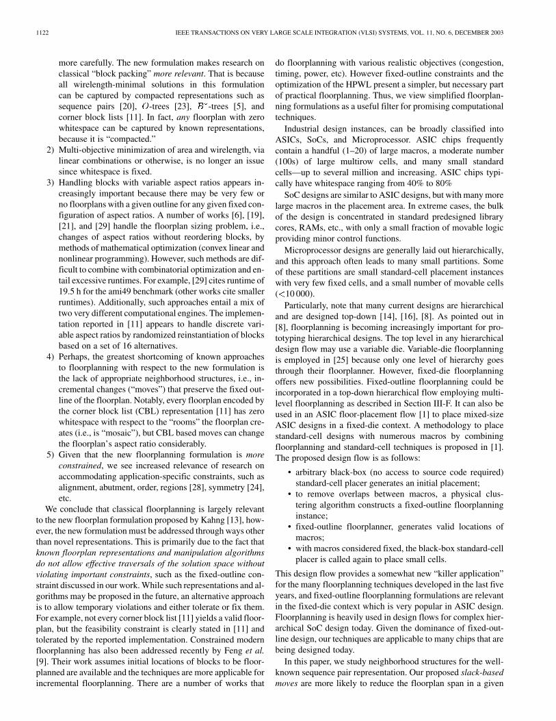
Fig. 2. Layout of a modern chip. (a) Actual layout. (b) Abstract floorplancaptured from the layout in (a). Example illustrates the hierarchical nature ofdesigns and the need to support a hierarchical flow.
et al. [11]. 1) Implies that the whitespace is no longer anobjective, but rather a constraint, because it can be computedin advance. Modern design flows use hierarchy as a means toreduce the complexity. Fig. 2(a) shows the layout of a modernchip. Fig. 2(b) abstracts the actual layout in (a) to generate ahierarchical floorplan. This example serves to illustrate theneed to support a hierarchical flow.
The modern floorplanning formulation was proposed byKahng [13] and is an “inside-out” version of the classicaloutline-free floorplanning formulation—the aspect ratio ofthe floorplan is fixed, but the aspect ratios of the blocks canvary. It has not yet been explicitly addressed in the literature,partly due to the lack of benchmarks. Since our work addressesthis formulation, we reevaluate the relevance of classicalfloorplanning results in the new context.
1) Zero whitespace requirement is practical because attop level (during floorplanning) there are no unusedresources—the space between blocks can be used forrouting, buffers, etc. For example, “buffer islands” arediscussed in [7]. Therefore, whitespace must be allocated
1122 IEEE TRANSACTIONS ON VERY LARGE SCALE INTEGRATION (VLSI) SYSTEMS, VOL. 11, NO. 6, DECEMBER 2003
more carefully. The new formulation makes research onclassical “block packing” more relevant. That is becauseall wirelength-minimal solutions in this formulationcan be captured by compacted representations such assequence pairs [20], -trees [23], -trees [5], andcorner block lists [11]. In fact, any floorplan with zerowhitespace can be captured by known representations,because it is “compacted.”
2) Multi-objective minimization of area and wirelength, vialinear combinations or otherwise, is no longer an issuesince whitespace is fixed.
3) Handling blocks with variable aspect ratios appears in-creasingly important because there may be very few orno floorplans with a given outline for any given fixed con-figuration of aspect ratios. A number of works [6], [19],[21], and [29] handle the floorplan sizing problem, i.e.,changes of aspect ratios without reordering blocks, bymethods of mathematical optimization (convex linear andnonlinear programming). However, such methods are dif-ficult to combine with combinatorial optimization and en-tail excessive runtimes. For example, [29] cites runtime of19.5 h for the ami49 benchmark (other works cite smallerruntimes). Additionally, such approaches entail a mix oftwo very different computational engines. The implemen-tation reported in [11] appears to handle discrete vari-able aspect ratios by randomized reinstantiation of blocksbased on a set of 16 alternatives.
4) Perhaps, the greatest shortcoming of known approachesto floorplanning with respect to the new formulation isthe lack of appropriate neighborhood structures, i.e., in-cremental changes (“moves”) that preserve the fixed out-line of the floorplan. Notably, every floorplan encoded bythe corner block list (CBL) representation [11] has zerowhitespace with respect to the “rooms” the floorplan cre-ates (i.e., is “mosaic”), but CBL based moves can changethe floorplan’s aspect ratio considerably.
5) Given that the new floorplanning formulation is moreconstrained, we see increased relevance of research onaccommodating application-specific constraints, such asalignment, abutment, order, regions [28], symmetry [24],etc.
We conclude that classical floorplanning is largely relevantto the new floorplan formulation proposed by Kahng [13], how-ever, the new formulation must be addressed through ways otherthan novel representations. This is primarily due to the fact thatknown floorplan representations and manipulation algorithmsdo not allow effective traversals of the solution space withoutviolating important constraints, such as the fixed-outline con-straint discussed in our work. While such representations and al-gorithms may be proposed in the future, an alternative approachis to allow temporary violations and either tolerate or fix them.For example, not every corner block list [11] yields a valid floor-plan, but the feasibility constraint is clearly stated in [11] andtolerated by the reported implementation. Constrained modernfloorplanning has also been addressed recently by Feng et al.[9]. Their work assumes initial locations of blocks to be floor-planned are available and the techniques are more applicable forincremental floorplanning. There are a number of works that
do floorplanning with various realistic objectives (congestion,timing, power, etc). However fixed-outline constraints and theoptimization of the HPWL present a simpler, but necessary partof practical floorplanning. Thus, we view simplified floorplan-ning formulations as a useful filter for promising computationaltechniques.
Industrial design instances, can be broadly classified intoASICs, SoCs, and Microprocessor. ASIC chips frequentlycontain a handful (1–20) of large macros, a moderate number(100s) of large multirow cells, and many small standardcells—up to several million and increasing. ASIC chips typi-cally have whitespace ranging from 40% to 80%
SoC designs are similar to ASIC designs, but with many morelarge macros in the placement area. In extreme cases, the bulkof the design is concentrated in standard predesigned librarycores, RAMs, etc., with only a small fraction of movable logicproviding minor control functions.
Microprocessor designs are generally laid out hierarchically,and this approach often leads to many small partitions. Someof these partitions are small standard-cell placement instanceswith very few fixed cells, and a small number of movable cells( 10 000).
Particularly, note that many current designs are hierarchicaland are designed top-down [14], [16], [8]. As pointed out in[8], floorplanning is becoming increasingly important for pro-totyping hierarchical designs. The top level in any hierarchicaldesign flow may use a variable die. Variable-die floorplanningis employed in [25] because only one level of hierarchy goesthrough their floorplanner. However, fixed-die floorplanningoffers new possibilities. Fixed-outline floorplanning could beincorporated in a top-down hierarchical flow employing multi-level floorplanning as described in Section III-F. It can also beused in an ASIC floor-placement flow [1] to place mixed-sizeASIC designs in a fixed-die context. A methodology to placestandard-cell designs with numerous macros by combiningfloorplanning and standard-cell techniques is proposed in [1].The proposed design flow is as follows:
• arbitrary black-box (no access to source code required)standard-cell placer generates an initial placement;
• to remove overlaps between macros, a physical clus-tering algorithm constructs a fixed-outline floorplanninginstance;
• fixed-outline floorplanner, generates valid locations ofmacros;
• with macros considered fixed, the black-box standard-cellplacer is called again to place small cells.
This design flow provides a somewhat new “killer application”for the many floorplanning techniques developed in the last fiveyears, and fixed-outline floorplanning formulations are relevantin the fixed-die context which is very popular in ASIC design.Floorplanning is heavily used in design flows for complex hier-archical SoC design today. Given the dominance of fixed-out-line design, our techniques are applicable to many chips that arebeing designed today.
In this paper, we study neighborhood structures for the well-known sequence pair representation. Our proposed slack-basedmoves are more likely to reduce the floorplan span in a given
ADYA AND MARKOV: FIXED-OUTLINE FLOORPLANNING: ENABLING HIERARCHICAL DESIGN 1123
direction (H or V) than random pair-wise swaps and block rota-tions used in most works based on sequence pairs. Wirelengthminimization and handling aspect ratios of soft blocks are alsomore transparent with slack-based moves.
The remaining part of the paper is organized as follows.Section II discusses the background on floorplanning andthe sequence pair representation. We introduce the conceptof floorplan slack in Section III, and also discusss betterlocal-search in the annealing context and special moves aimedat HPWL minimization and handling soft-blocks using slacks.Fixed-outline floorplanning and applications to hierarchicalfloorplan design is also explained. Section IV presents empir-ical validation of our work and future directions are discussedin Section V.
II. BACKGROUND: THE SEQUENCE PAIR
FLOORPLAN REPRESENTATION
An overwhelming majority of floorplanners rely on the sim-ulated annealing framework [26] but differ by internal floorplanrepresentations.
The sequence pair representation for classical floorplans ofblocks has been proposed in [20]. Unlike most new graph-basedrepresentations, it consists of two permutations (orderings) ofthe blocks. The two permutations capture geometric relationsbetween each pair of blocks. Recall that since blocks cannotoverlap, one of them must be to the left or below from the other,or both. In sequence pair
(1)
In other words, every two blocks constrain each other in eithervertical or horizontal direction. The sequence pair represen-tation is shift invariant since it only encodes pairwise relativeplacements. Therefore, placements produced from sequencepairs must be aligned to given horizontal and vertical axes,e.g., and . Multiple sequence pairs may encode thesame block placement, e.g., for three identical square blocks,both , and encode theplacement with straight on top of , and aligned with onthe right.
The original work on the sequence pair representation[20] proposed an algorithm to compute placements from asequence pair by constructing the horizontal (H) and vertical(V) constraint graphs. The H and V graphs have verticeseach—one for each of block, plus “the source” and “thesink.” For every pair of blocks and there is a directed edge
in the graph if is to the left of according to thesequence pair [(1)]. Similarly there is a directed edgein the graph if is above according to the sequence pair[(1)]—exactly one of the two cases must take place. Verticesthat do not have outgoing edges are connected to the sink, andvertices that do not have incoming edges are connected to thesource. Both graphs are considered vertex-weighted, where theweights in the H graph represent horizontal sizes of blocks, andthe weights in the V graph represent vertical sizes of blocks.Sources and sinks have zero weights.
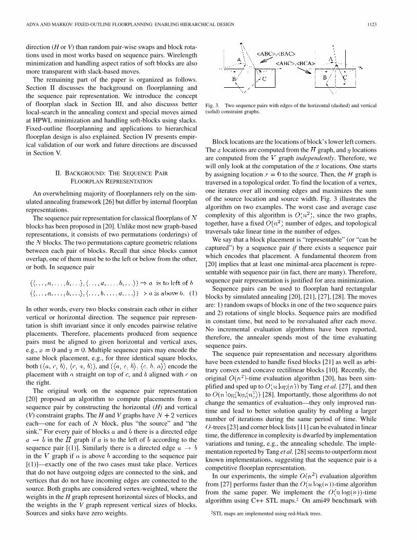
Fig. 3. Two sequence pairs with edges of the horizontal (dashed) and vertical(solid) constraint graphs.
Block locations are the locations of block’s lower left corners.The locations are computed from the graph, and locationsare computed from the graph independently. Therefore, wewill only look at the computation of the locations. One startsby assigning location to the source. Then, the graph istraversed in a topological order. To find the location of a vertex,one iterates over all incoming edges and maximizes the sumof the source location and source width. Fig. 3 illustrates thealgorithm on two examples. The worst case and average casecomplexity of this algorithm is , since the two graphs,together, have a fixed number of edges, and topologicaltraversals take linear time in the number of edges.
We say that a block placement is “representable” (or “can becaptured”) by a sequence pair if there exists a sequence pairwhich encodes that placement. A fundamental theorem from[20] implies that at least one minimal-area placement is repre-sentable with sequence pair (in fact, there are many). Therefore,sequence pair representation is justified for area minimization.
Sequence pairs can be used to floorplan hard rectangularblocks by simulated annealing [20], [21], [27], [28]. The movesare: 1) random swaps of blocks in one of the two sequence pairsand 2) rotations of single blocks. Sequence pairs are modifiedin constant time, but need to be reevaluated after each move.No incremental evaluation algorithms have been reported,therefore, the annealer spends most of the time evaluatingsequence pairs.
The sequence pair representation and necessary algorithmshave been extended to handle fixed blocks [21] as well as arbi-trary convex and concave rectilinear blocks [10]. Recently, theoriginal -time evaluation algorithm [20], has been sim-plified and sped up to by Tang et al. [27], and thento [28]. Importantly, those algorithms do notchange the semantics of evaluation—they only improved run-time and lead to better solution quality by enabling a largernumber of iterations during the same period of time. While
-trees [23] and corner block lists [11] can be evaluated in lineartime, the difference in complexity is dwarfed by implementationvariations and tuning, e.g., the annealing schedule. The imple-mentation reported by Tang et al. [28] seems to outperform mostknown implementations, suggesting that the sequence pair is acompetitive floorplan representation.
In our experiments, the simple evaluation algorithmfrom [27] performs faster than the -time algorithmfrom the same paper. We implement the -timealgorithm using C++ STL maps.2 On ami49 benchmark with
2STL maps are implemented using red-black trees.
1124 IEEE TRANSACTIONS ON VERY LARGE SCALE INTEGRATION (VLSI) SYSTEMS, VOL. 11, NO. 6, DECEMBER 2003
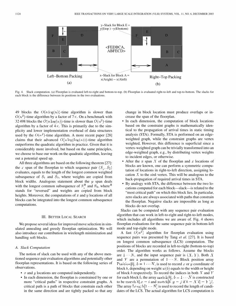
Fig. 4. Slack computation. (a) Floorplan is evaluated left-to-right and bottom-to-top. (b) Floorplan is evaluated right-to-left and top-to-bottom. The slacks foreach block is the difference between its positions in the two evaluations.
49 blocks the -time algorithm is slower than-time algorithm by a factor of 7 . On a benchmark with
32 498 blocks the -time is slower than -timealgorithm by a factor of 4 . This is primarily due to the sim-plicity and lower implementation overhead of data structuresused by the -time algorithm. A more recent paper [28]claims that their advanced -time algorithmoutperforms the quadratic algorithm in practice. Given that it isconsiderably more involved, but based on the same principles,we choose to base our work on the quadratic algorithm, leavingout a potential speed up.
All three algorithms are based on the following theorem [27]:the span of the floorplan to which sequence pairevaluates, equals to the length of the longest common weightedsubsequence of and , where weights are copied fromblock widths. Analogous statement about the span dealswith the longest common subsequence of and , wherestands for “reversed” and weights are copied from blockheights. Moreover, the computations of and locations of allblocks can be integrated into the longest common subsequencecomputations.
III. BETTER LOCAL SEARCH
We propose several ideas for improved move selection in sim-ulated annealing and greedy floorplan optimization. We willalso introduce our contribution in wirelength minimization andhandling soft blocks.
A. Slack Computation
The notion of slack can be used with any of the above men-tioned sequence pair evaluation algorithms and potentially otherfloorplan representations. It is based on the following series ofobservations.
• and locations are computed independently.• In each dimension, the floorplan is constrained by one or
more “critical paths” in respective constraint graphs. Acritical path is a path of blocks that constrain each otherin the same direction and are tightly packed so that any
change in block location must produce overlaps or in-crease the span of the floorplan.
• In each dimension, the computation of block locationsbased on the constraint graphs is mathematically iden-tical to the propagation of arrival times in static timinganalysis (STA). Formally, STA is performed on an edge-weighted graph, while the constraint graphs are vertexweighted, However, this difference is superficial since avertex-weighted graph can be trivially transformed into anedge-weighted graph, e.g., by distributing vertex weightsto incident edges, or otherwise.
• After the span of the floorplan and locations ofblocks are known, one can perform a symmetric compu-tation of locations in right-to-left direction, assigning lo-cation to the sink vertex. This will be analogous to theback-propagation of required arrival times in STA.
• By analogy with STA, the difference between the two lo-cations computed for each block—slack—is related to the“most critical path” on which this block lies. In particular,zero slacks are always associated with paths that constrainthe floorplan. Negative slacks are impossible as long asblocks do not overlap.
Slacks can be computed with any sequence pair evaluationalgorithm that can work in left-to-right and right-to-left modes,which includes all algorithms we are aware of. Fig. 4 showsfloorplan evaluations for the same sequence pair in bottom-leftmode and top-right mode.
A fast algorithm for floorplan evaluation usingsequence pairs was presented by Tang et al. [27]. It is basedon longest common subsequence (LCS) computation. Thepositions of blocks are recorded in left-to-right (bottom-to-top)order. The algorithm works as follows. Assume the blocksare , and the input sequence pair is . Bothand are a permutation of . Block position array
, is used to record or coordinate ofblock , depending on weight equals to the width or heightof block respectively. To record the indices in both andfor each block , the array is constructedto be and if .The array is used to record the length of candi-dates of the LCS. The actual algorithm for LCS computation is

ADYA AND MARKOV: FIXED-OUTLINE FLOORPLANNING: ENABLING HIERARCHICAL DESIGN 1125
Fig. 5. Pseudocode for LCS_ORIG. (X;Y ) is the input sequence pair. The computation is in left-to-right mode.
Fig. 6. Pseudocode for SP_EVAL_ORIG. It computes the location of blocks in bottom-left mode. xSize and ySize are the floorplan span. widths[1 � � �N ] andheights[1 � � �N ] hold the dimensions of blocks.
Fig. 7. Pseudocode for SP_EVAL_REV. It computes the location of blocks in top-right mode. SP_EVAL_REV reverses the two sequences of the sequence pairbefore calculating the LCS.
shown in Fig. 5. To calculate the actual positions of the blockstwo calls to LCS_ORIG are made. X-positions are calculated byinitializing the weights array with the widthsof blocks and invoking LCS_ORIG( ). Y-positionsare calculated by initializing the weights array withthe heights of blocks and invoking LCS_ORIG( ),where is the sequence in reversed order. Fig. 6 showsthe pseudo code to evaluate the floorplan in bottom-left mode,given a sequence pair using LCS computations.
To evaluate the floorplan in the top-right mode we need toevaluate the LCS of the two sequences in right-to-left order.This can be achieved easily by reversing the two sequences andinvoking LCS_ORIG. The pseudo code for SP_EVAL_REV ispresented in Fig. 7. It reverses the two sequences, andbefore calling the original algorithm. To compute the slacks weneed the locations of the bottom-left corner of each block whenevaluating the sequence pair in top-right mode. Lines 12 through16 of SP_EVAL_REV achieve this.
1126 IEEE TRANSACTIONS ON VERY LARGE SCALE INTEGRATION (VLSI) SYSTEMS, VOL. 11, NO. 6, DECEMBER 2003
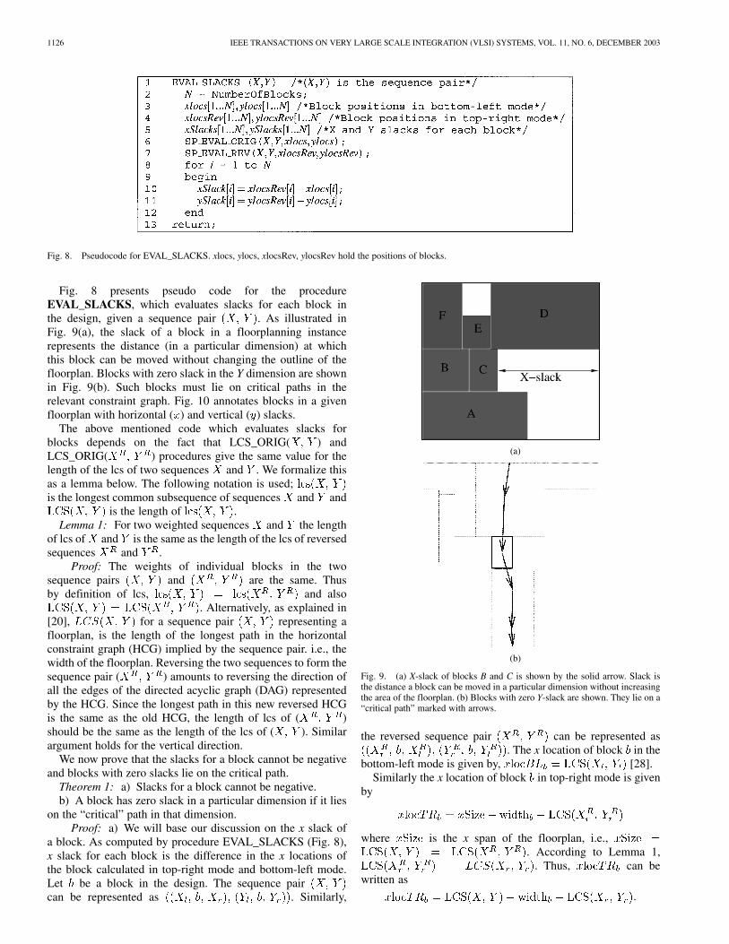
Fig. 8. Pseudocode for EVAL_SLACKS. xlocs, ylocs, xlocsRev, ylocsRev hold the positions of blocks.
Fig. 8 presents pseudo code for the procedureEVAL_SLACKS, which evaluates slacks for each block inthe design, given a sequence pair . As illustrated inFig. 9(a), the slack of a block in a floorplanning instancerepresents the distance (in a particular dimension) at whichthis block can be moved without changing the outline of thefloorplan. Blocks with zero slack in the Y dimension are shownin Fig. 9(b). Such blocks must lie on critical paths in therelevant constraint graph. Fig. 10 annotates blocks in a givenfloorplan with horizontal ( ) and vertical ( ) slacks.
The above mentioned code which evaluates slacks forblocks depends on the fact that LCS_ORIG( ) andLCS_ORIG( ) procedures give the same value for thelength of the lcs of two sequences and . We formalize thisas a lemma below. The following notation is used;is the longest common subsequence of sequences and and
is the length of .Lemma 1: For two weighted sequences and the length
of lcs of and is the same as the length of the lcs of reversedsequences and .
Proof: The weights of individual blocks in the twosequence pairs and are the same. Thusby definition of lcs, and also
. Alternatively, as explained in[20], for a sequence pair representing afloorplan, is the length of the longest path in the horizontalconstraint graph (HCG) implied by the sequence pair. i.e., thewidth of the floorplan. Reversing the two sequences to form thesequence pair ( ) amounts to reversing the direction ofall the edges of the directed acyclic graph (DAG) representedby the HCG. Since the longest path in this new reversed HCGis the same as the old HCG, the length of lcs of ( )should be the same as the length of the lcs of ( ). Similarargument holds for the vertical direction.
We now prove that the slacks for a block cannot be negativeand blocks with zero slacks lie on the critical path.
Theorem 1: a) Slacks for a block cannot be negative.b) A block has zero slack in a particular dimension if it lies
on the “critical” path in that dimension.Proof: a) We will base our discussion on the x slack of
a block. As computed by procedure EVAL_SLACKS (Fig. 8),x slack for each block is the difference in the x locations ofthe block calculated in top-right mode and bottom-left mode.Let be a block in the design. The sequence paircan be represented as . Similarly,
(a)
(b)
Fig. 9. (a) X-slack of blocks B and C is shown by the solid arrow. Slack isthe distance a block can be moved in a particular dimension without increasingthe area of the floorplan. (b) Blocks with zero Y-slack are shown. They lie on a“critical path” marked with arrows.
the reversed sequence pair can be represented as. The x location of block in the
bottom-left mode is given by, [28].Similarly the x location of block in top-right mode is given
by
where is the x span of the floorplan, i.e.,. According to Lemma 1,
. Thus, can bewritten as

ADYA AND MARKOV: FIXED-OUTLINE FLOORPLANNING: ENABLING HIERARCHICAL DESIGN 1127
(a)
(b)
Fig. 10. A slack-based move in a highly suboptimal floorplan of benchmark hp. x and y slacks are shown as percentages of the respective spans of the floorplan.Module cmp3—the smallest with zero y slack—is moved upon the module cntu, which has the high y slack. This move improves vertical span and slightlyworsens the horizontal span, but the floorplan area is reduced.
For two sequences and , if, then
the lcs of sequences and is ,and the length of this {\rm lcs} is
, which cannot be greater than . Thus,by contradiction, the following inequality holds:
We have proved that for any block , its x slack is nonnegative.This holds true for the y slack too.
b) As above, we base our discussion on the x critical path.A critical path of a floorplan in x dimension is defined as thelongest x path of the floorplan. There can be more than one crit-ical path. However the length of all the critical paths is the sameand equal to the , where is the sequence pairrepresenting the floorplan. If a block lies on the x critical paththen is a part of the lcs of and . As shown in Theorem1-a), the following equality holds:
1128 IEEE TRANSACTIONS ON VERY LARGE SCALE INTEGRATION (VLSI) SYSTEMS, VOL. 11, NO. 6, DECEMBER 2003
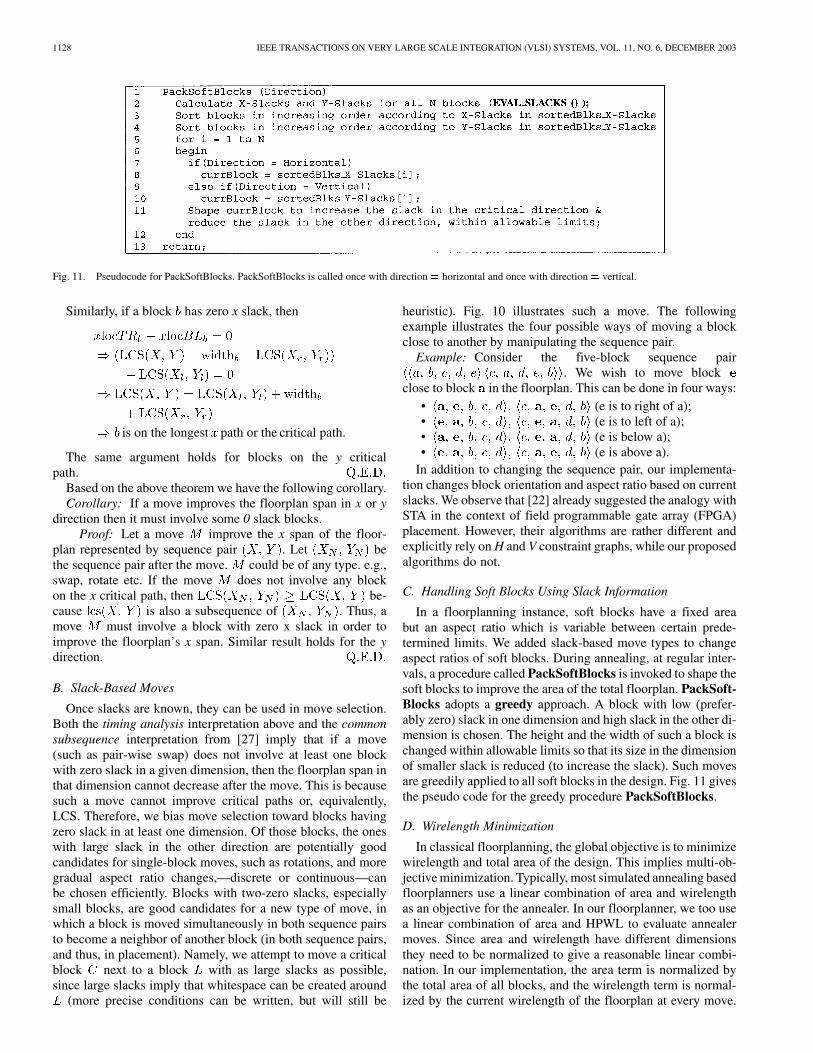
Fig. 11. Pseudocode for PackSoftBlocks. PackSoftBlocks is called once with direction = horizontal and once with direction = vertical.
Similarly, if a block has zero x slack, then
is on the longest path or the critical path.
The same argument holds for blocks on the y criticalpath.
Based on the above theorem we have the following corollary.Corollary: If a move improves the floorplan span in x or y
direction then it must involve some 0 slack blocks.Proof: Let a move improve the x span of the floor-
plan represented by sequence pair . Let bethe sequence pair after the move. could be of any type. e.g.,swap, rotate etc. If the move does not involve any blockon the x critical path, then be-cause is also a subsequence of . Thus, amove must involve a block with zero x slack in order toimprove the floorplan’s x span. Similar result holds for the ydirection.
B. Slack-Based Moves
Once slacks are known, they can be used in move selection.Both the timing analysis interpretation above and the commonsubsequence interpretation from [27] imply that if a move(such as pair-wise swap) does not involve at least one blockwith zero slack in a given dimension, then the floorplan span inthat dimension cannot decrease after the move. This is becausesuch a move cannot improve critical paths or, equivalently,LCS. Therefore, we bias move selection toward blocks havingzero slack in at least one dimension. Of those blocks, the oneswith large slack in the other direction are potentially goodcandidates for single-block moves, such as rotations, and moregradual aspect ratio changes,—discrete or continuous—canbe chosen efficiently. Blocks with two-zero slacks, especiallysmall blocks, are good candidates for a new type of move, inwhich a block is moved simultaneously in both sequence pairsto become a neighbor of another block (in both sequence pairs,and thus, in placement). Namely, we attempt to move a criticalblock next to a block with as large slacks as possible,since large slacks imply that whitespace can be created around
(more precise conditions can be written, but will still be
heuristic). Fig. 10 illustrates such a move. The followingexample illustrates the four possible ways of moving a blockclose to another by manipulating the sequence pair.
Example: Consider the five-block sequence pair. We wish to move block
close to block in the floorplan. This can be done in four ways:• (e is to right of a);• (e is to left of a);• (e is below a);• (e is above a).
In addition to changing the sequence pair, our implementa-tion changes block orientation and aspect ratio based on currentslacks. We observe that [22] already suggested the analogy withSTA in the context of field programmable gate array (FPGA)placement. However, their algorithms are rather different andexplicitly rely on H and V constraint graphs, while our proposedalgorithms do not.
C. Handling Soft Blocks Using Slack Information
In a floorplanning instance, soft blocks have a fixed areabut an aspect ratio which is variable between certain prede-termined limits. We added slack-based move types to changeaspect ratios of soft blocks. During annealing, at regular inter-vals, a procedure called PackSoftBlocks is invoked to shape thesoft blocks to improve the area of the total floorplan. PackSoft-Blocks adopts a greedy approach. A block with low (prefer-ably zero) slack in one dimension and high slack in the other di-mension is chosen. The height and the width of such a block ischanged within allowable limits so that its size in the dimensionof smaller slack is reduced (to increase the slack). Such movesare greedily applied to all soft blocks in the design. Fig. 11 givesthe pseudo code for the greedy procedure PackSoftBlocks.
D. Wirelength Minimization
In classical floorplanning, the global objective is to minimizewirelength and total area of the design. This implies multi-ob-jective minimization. Typically, most simulated annealing basedfloorplanners use a linear combination of area and wirelengthas an objective for the annealer. In our floorplanner, we too usea linear combination of area and HPWL to evaluate annealermoves. Since area and wirelength have different dimensionsthey need to be normalized to give a reasonable linear combi-nation. In our implementation, the area term is normalized bythe total area of all blocks, and the wirelength term is normal-ized by the current wirelength of the floorplan at every move.
ADYA AND MARKOV: FIXED-OUTLINE FLOORPLANNING: ENABLING HIERARCHICAL DESIGN 1129
The term in the simulated annealing algorithm is calculatedas follows
is the linear weight attributed to the HPWL termand its value is between 0 and 1. During the annealing, all movesfor which is negative are accepted. All moves with a positiveare accepted if ,where is a random number between 0 and 1. Thus theprobability of accepting a bad move decreases as isreduced.
Additional moves are designed to improve the wirelength. Fora given block , we calculate, using analytical techniques, its“ideal” location that would minimize quadratic wirelength ofits incident wires.3 We determine the ideal location ofblock which minimizes the following function
The ideal location of block is simply the averageof the position of all modules connected to block . We thenidentify the block closest to the ideal location. This is done byexpanding a circle centered at the ideal location and identifyingthe closest block . We then attempt to move block in thesequence pair so that in both sequences it is located next to . Asexplained in Section III-A, we evaluate the four possible waysto do that, and choose the best. Thus an attempt is made to move
close to its ideal location to minimize quadratic wirelength.Another type of move attempts to minimize both the floorplan
size and wirelength objectives at the same time. Find a blockclosest to the ideal location of the chosen block such that theblock has large slack in at least one dimension. Dependingon whether has a large slack in the X dimension or in the Ydimension, we place with a horizontal relation or a verticalconstraint relative to , respectively. Empirical measurementsconfirm that adding the proposed move types improves finalfloorplans.
E. Fixed-Outline Constraints
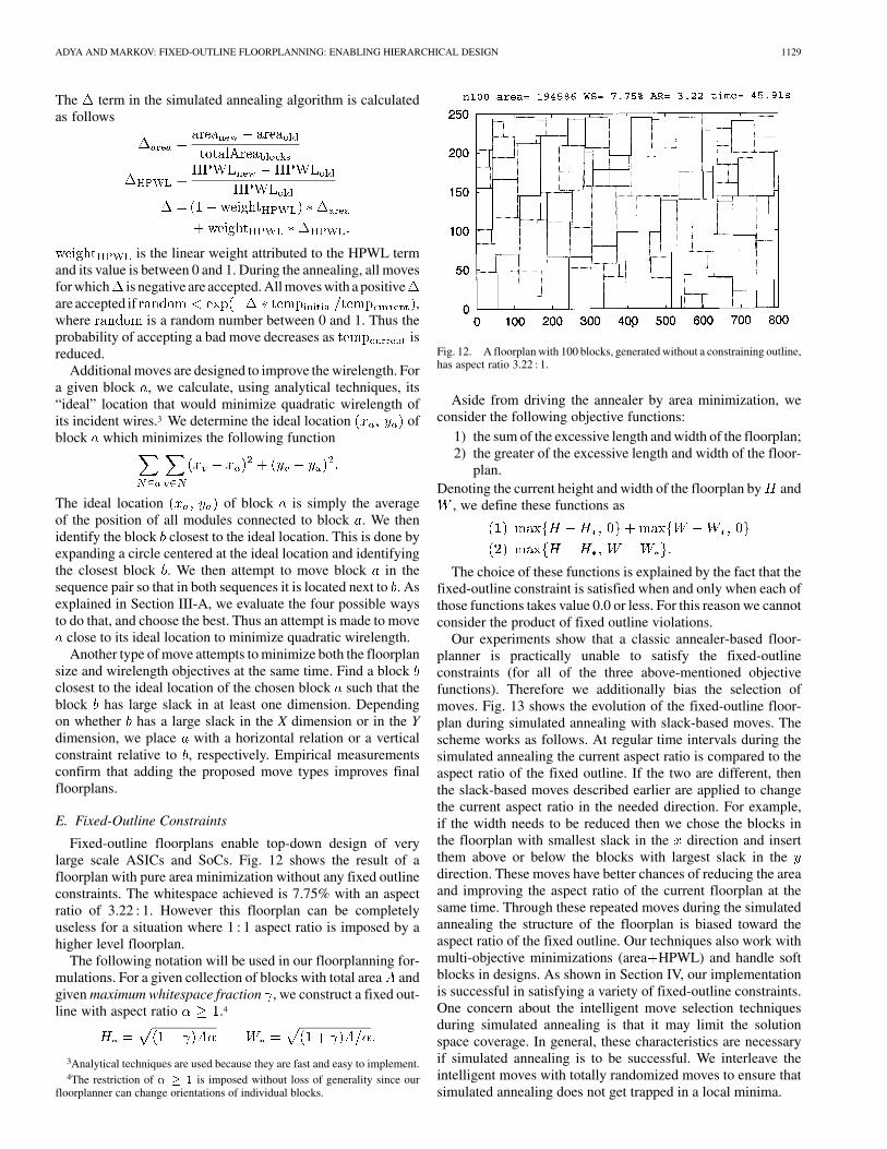
Fixed-outline floorplans enable top-down design of verylarge scale ASICs and SoCs. Fig. 12 shows the result of afloorplan with pure area minimization without any fixed outlineconstraints. The whitespace achieved is 7.75% with an aspectratio of 3.22 : 1. However this floorplan can be completelyuseless for a situation where 1 : 1 aspect ratio is imposed by ahigher level floorplan.
The following notation will be used in our floorplanning for-mulations. For a given collection of blocks with total area andgiven maximum whitespace fraction , we construct a fixed out-line with aspect ratio .4
3Analytical techniques are used because they are fast and easy to implement.4The restriction of � � 1 is imposed without loss of generality since our
floorplanner can change orientations of individual blocks.
Fig. 12. A floorplan with 100 blocks, generated without a constraining outline,has aspect ratio 3.22 : 1.
Aside from driving the annealer by area minimization, weconsider the following objective functions:
1) the sum of the excessive length and width of the floorplan;2) the greater of the excessive length and width of the floor-
plan.Denoting the current height and width of the floorplan by and
, we define these functions as
The choice of these functions is explained by the fact that thefixed-outline constraint is satisfied when and only when each ofthose functions takes value 0.0 or less. For this reason we cannotconsider the product of fixed outline violations.
Our experiments show that a classic annealer-based floor-planner is practically unable to satisfy the fixed-outlineconstraints (for all of the three above-mentioned objectivefunctions). Therefore we additionally bias the selection ofmoves. Fig. 13 shows the evolution of the fixed-outline floor-plan during simulated annealing with slack-based moves. Thescheme works as follows. At regular time intervals during thesimulated annealing the current aspect ratio is compared to theaspect ratio of the fixed outline. If the two are different, thenthe slack-based moves described earlier are applied to changethe current aspect ratio in the needed direction. For example,if the width needs to be reduced then we chose the blocks inthe floorplan with smallest slack in the direction and insertthem above or below the blocks with largest slack in thedirection. These moves have better chances of reducing the areaand improving the aspect ratio of the current floorplan at thesame time. Through these repeated moves during the simulatedannealing the structure of the floorplan is biased toward theaspect ratio of the fixed outline. Our techniques also work withmulti-objective minimizations (area HPWL) and handle softblocks in designs. As shown in Section IV, our implementationis successful in satisfying a variety of fixed-outline constraints.One concern about the intelligent move selection techniquesduring simulated annealing is that it may limit the solutionspace coverage. In general, these characteristics are necessaryif simulated annealing is to be successful. We interleave theintelligent moves with totally randomized moves to ensure thatsimulated annealing does not get trapped in a local minima.

1130 IEEE TRANSACTIONS ON VERY LARGE SCALE INTEGRATION (VLSI) SYSTEMS, VOL. 11, NO. 6, DECEMBER 2003
Fig. 13. Snap-shots from fixed-outline floorplanning. The number ofannealing moves is fixed, but if the evolving floorplan fits within the requiredfixed-outline, annealing is stopped earlier. If at the end of annealing thefixed-outline constraints are not satisfied, it is considered a failure and a freshattempt is made.
F. Hierarchical Layout
Hierarchical design is becoming increasingly attractive as away to manage design complexity [18], [15]. It is argued in[18] that hierarchy is needed for humans, not for algorithms.The need for hierarchical design makes it imperative that thewhole design flow support a hierarchical design methodology.We argue that fixed-outline floorplanning is an integral compo-nent of such a multilevel hierarchical flow. As discussed in [15],the top level floorplan might need to be fixed early on in thedesign cycle to avoid costly iterations later. Once the top-levelfloorplan is finalized, the high-level blocks and their shapes im-pose a fixed-outline constraint on the lower levels of design. Adesign team might decide to implement each high-level blockflat, in which case there would be no need for a fixed-outlinefloorplanning tool. However, if the design team decides to im-plement high-level blocks in a hierarchical fashion as well thenfixed-outline floorplanning becomes necessary. With increasingchip sizes, such a scenario is not unrealistic.
We use our techniques in fixed-outline floorplanning to de-velop a hierarchical floorplanning flow which is justified forvery large ASICS and SoCs. We employ a simple connectivitybased clustering scheme to create a top-level of hierarchy withclustered blocks. Each top-level clustered block is soft with as-pect ratios allowed from 0.75 to 1.5 and has an area equal to1.15 sum of area of all subblocks. Thus a whitespace of 15%is allotted to each top-level block, so that Parquet can find a so-lution satisfying the fixed-outline constraints. The connectivitybased clustering we use, is a multilevel greedy approach em-ploying a series of passes until the design reduces to manage-able size. In each pass we group highly connected cells together.Thus the design size reduces by a factor of 2 in each pass. We re-move any net that connects cells only within a cluster. More in-volved clustering schemes, like multiway partitioning, could beemployed for better HPWL minimization. We use these experi-ments to show that the fixed-outline floorplanner acts as an en-gine to enable hierarchical floorplanning. The top-level design
is floorplanned without any fixed-outline constraints and the ob-jective is to minimize area. The top-level clustered blocks im-pose fixed-outline constraints on the subblocks. Each top-levelblock is now floorplanned with these constraints.
IV. EMPIRICAL VALIDATION
We implement a floorplanner based on simulated annealing,Parquet-1. Runtimes are measured (in seconds) on a 1000 MHzPC/Intel system that runs Linux. Implementations are in C++and compiled with .5
A. Annealing Schedule
Parquet-1 mostly follows a geometric cooling schedule.The initial temperature is chosen to be high enough (i.e.,
) for most designs under consideration.For a design with blocks, the temperature is decreased by afactor of every moves, as follows:
At certain deterministically defined temperatures, varies. Thecooling is rapid in the initial phase (low value of ) and veryslow at the end (high value of ). Thus most of the time duringannealing is spent at low temperatures. is changed with tem-perature as follows
There is also an option to run the annealer for a specified lengthof time. In this mode the temperature schedule remains the samebut the number of moves between each iteration changes.
B. Classical Floorplanning Context
Table I compares Parquet-1 to leading-edge floorplanningresults on standard MCNC benchmarks in the area-only mini-mization context with no fixed-outline constraints. According tothose results, our floorplanner is competitive with published im-plementations both in terms of final area and runtimes. We note,however, that all recently reported floorplanners easily achievewhitespace well below 10%, therefore leaving very little pos-sible improvement.
Table II shows results for simultaneous minimization of areaand wirelength in a design. Results for different wirelengthweights are presented.
Table III presents the area minimization results for designswith soft blocks. All blocks have a variable aspect ratio. Table IVpresents the area and HPWL minimization results for designswith soft blocks.
In Section IV-C, we show that fixed-outline floorplanning issignificantly harder than outline-free floorplanning.
5The C++ source code of Parquet is available on the Web at http://vl-sicad.eecs.umich.edu/BK/parquet/.

ADYA AND MARKOV: FIXED-OUTLINE FLOORPLANNING: ENABLING HIERARCHICAL DESIGN 1131
TABLE IOUTLINE-FREE AREA MINIMIZATION RESULTS FOR ENHANCED O-TREE (ON SUN ULTRA60), TCG (ON SUN ULTRA60), CBL (ON SUN SPARC 20), FAST-SP
(ON SUN ULTRA 1) AND PARQUET-1 (ON 1000 MHz PC/INTEL SYSTEM). AVERAGES AND MINIMA FOR PARQUET-1 ARE OVER 100 INDEPENDENT STARTS
TABLE IIOUTLINE-FREE, AREA + HPWL MINIMIZATION RESULTS. A LINEAR COMBINATION OF AREA AND HALF PERIMETER WIRELENGTH IS MINIMIZED DURING
SIMULATED ANNEALING. RESULTS FOR DIFFERENT HPWL WEIGHTS ARE PRESENTED. AVERAGES AND MINIMA ARE OVER 100 INDEPENDENT STARTS
TABLE IIIOUTLINE-FREE, AREA MINIMIZATION RESULTS WITH SOFT BLOCKS.
SLACK-BASED MOVES ARE APPLIED DURING ANNEALING TO MODIFY THE
ASPECT RATIO OF SOFT BLOCKS. ALL BLOCKS HAVE A VARIABLE ASPECT
RATIO. AVERAGES AND MINIMA ARE OVER 100 INDEPENDENT STARTS
C. Fixed-Outline Floorplanning
The standard version of the floorplanner, without any of theslack based moves could not solve a single instance within thefixed outline, although it gave competitive area results. We trieddifferent objective functions to drive the annealer as explainedin Section III-E. When using the objective of minimizing thesum of excessive length and excessive width of the floorplan,the final aspect ratio of the floorplan is biased slightly toward therequired aspect ratio. However, just changing the objective func-tion was not powerful enough and the floorplanner could not sat-isfy the fixed-outline constraints for a single instance. This con-firms the inadequacy of the classical minimum-area (min-area)floorplanning formulation and algorithms in the fixed-outlinecontext.
To achieve fixed-outline floorplan, we consider three objec-tives in terms of excessive height and width as described inSection III-E (the sum of and the greater of) and the area. Westop the annealer as soon as it finds a solution satisfying a given
TABLE IVOUTLINE-FREE, AREA+ HPWL MINIMIZATION RESULTS WITH SOFT BLOCKS.
AVERAGES AND MINIMA ARE OVER 100 INDEPENDENT STARTS
fixed outline. If the current outline is smaller, its aspect ratiocan be different from the aspect ratio of the fixed outline. If theannealer’s temperature schedule runs out and no satisfying so-lution is found, we deem this a failure.
We constrained our final solutions to have a maximum white-space of 15% and tried to achieve floorplans satisfying differentfixed-outlines. Experiments are performed on n100 benchmarkand the results are averaged for 50 runs for each aspect ratio.
Fig. 14 shows plots of: 1) the probability of success of sat-isfying the fixed outline constraint versus desired aspect ratioof the fixed outline and 2) the average runtimes for all runsversus the desired aspect ratio of fixed outline. The plots reflectthe difficulty in satisfying fixed-outline floorplans with givenaspect ratios, which highly depends on the dimensions of theblocks. As seen from the plots, our simulated annealer fairlyoften failed to satisfy the given outline, however, the probabilityof success is typically over 50%, i.e., at least five in ten startsare successful. This consistent rate of success suggests that ourslack-based moves indeed improve local search (simulated an-nealing without slack-based moves is never able to satisfy the
1132 IEEE TRANSACTIONS ON VERY LARGE SCALE INTEGRATION (VLSI) SYSTEMS, VOL. 11, NO. 6, DECEMBER 2003
Fig. 14. Probability of success and average runtimes for floorplanningdesign n100 with fixed-outline constraints performed by annealing withthree alternative objective functions and slack-based moves. The maximumwhitespace for the design is 15%. i.e., = 15%. In order to remove noise weplotted average of 50 runs for each aspect ratio.
fixed outline). Also note that in most of the unsuccessful at-tempts the final solutions are within 1–2% from the desired out-line, yet we regard them as failures.
Out of the three objective functions we tried, minimizing thesum of excessive width and height and minimizing the area ismore successful than minimizing the maximum of excessivewidth or height. Finding an explanation of this empirical resultremains an open problem.
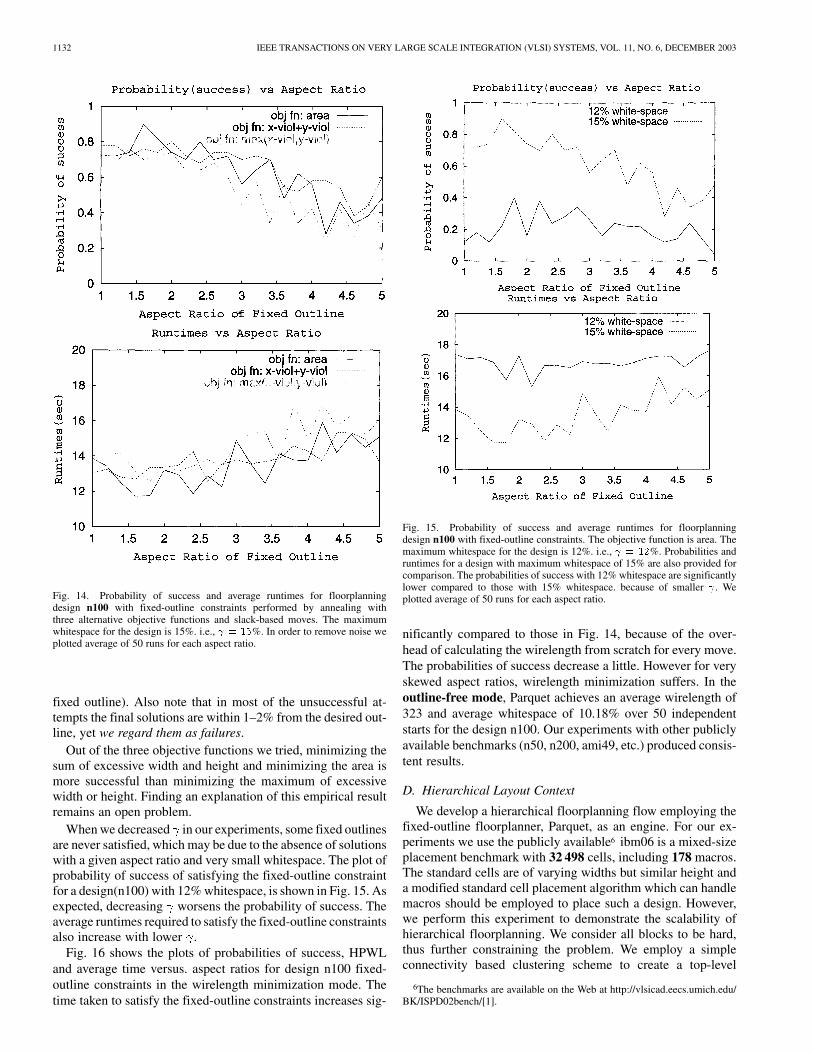
When we decreased in our experiments, some fixed outlinesare never satisfied, which may be due to the absence of solutionswith a given aspect ratio and very small whitespace. The plot ofprobability of success of satisfying the fixed-outline constraintfor a design(n100) with 12% whitespace, is shown in Fig. 15. Asexpected, decreasing worsens the probability of success. Theaverage runtimes required to satisfy the fixed-outline constraintsalso increase with lower .
Fig. 16 shows the plots of probabilities of success, HPWLand average time versus. aspect ratios for design n100 fixed-outline constraints in the wirelength minimization mode. Thetime taken to satisfy the fixed-outline constraints increases sig-
Fig. 15. Probability of success and average runtimes for floorplanningdesign n100 with fixed-outline constraints. The objective function is area. Themaximum whitespace for the design is 12%. i.e., = 12%. Probabilities andruntimes for a design with maximum whitespace of 15% are also provided forcomparison. The probabilities of success with 12% whitespace are significantlylower compared to those with 15% whitespace. because of smaller . Weplotted average of 50 runs for each aspect ratio.
nificantly compared to those in Fig. 14, because of the over-head of calculating the wirelength from scratch for every move.The probabilities of success decrease a little. However for veryskewed aspect ratios, wirelength minimization suffers. In theoutline-free mode, Parquet achieves an average wirelength of323 and average whitespace of 10.18% over 50 independentstarts for the design n100. Our experiments with other publiclyavailable benchmarks (n50, n200, ami49, etc.) produced consis-tent results.
D. Hierarchical Layout Context
We develop a hierarchical floorplanning flow employing thefixed-outline floorplanner, Parquet, as an engine. For our ex-periments we use the publicly available6 ibm06 is a mixed-sizeplacement benchmark with 32 498 cells, including 178 macros.The standard cells are of varying widths but similar height anda modified standard cell placement algorithm which can handlemacros should be employed to place such a design. However,we perform this experiment to demonstrate the scalability ofhierarchical floorplanning. We consider all blocks to be hard,thus further constraining the problem. We employ a simpleconnectivity based clustering scheme to create a top-level
6The benchmarks are available on the Web at http://vlsicad.eecs.umich.edu/BK/ISPD02bench/[1].

ADYA AND MARKOV: FIXED-OUTLINE FLOORPLANNING: ENABLING HIERARCHICAL DESIGN 1133
Fig. 16. Probability of success, HPWL and average runtimes for floorplanningdesign n100 with fixed-outline constraints in HPWL minimization mode. Themaximum whitespace for the design is 15%. i.e., = 15%. The probabilitiesof success are slightly lower compared to Fig. 14, because of multiobjectiveminimization. Also, the wirelength minimization suffers when required aspectratios are skewed. We plotted average of 50 runs for each aspect ratio.
of hierarchy with 238 clustered blocks (each top-level blockhaving approximately 128 blocks). Big macros are kept outof this clustering. A whitespace of 15% is allotted to eachtop-level clustered block. Each top-level clustered block issoft with aspect ratios allowed from 0.75 to 1.5. The top-leveldesign is floorplanned without any fixed-outline constraintsand the objective is to minimize area. The top-level floorplanis shown in Fig. 17(a). The top-level clustered blocks imposefixed-outline constraints on the subblocks. Each top-levelblock is now floorplanned with these constraints. The final
flat floorplan of ibm06 is shown in Fig. 17(b). We achieveda dead-space of 17.44% in 37 minutes. In comparison floor-planning ibm06 design flat achieved a deadspace of 55.62% in1070 minutes. We tried speeding up the flat floorplanning byusing the fast sequence pair evaluation algorithm[27]. However, as pointed out in Section II,algorithm performed worse than algorithm. While,in our experiments we only used a single level of hierarchy,the flow could be easily changed to handle multiple levels offloorplanning hierarchy. Also, we considered only area as anobjective, but a linear combination of area and wirelength canalso be considered as an objective. We perform the hierarchicalfloorplanning experiment to demonstrate that multilevel floor-planning is much more scalable than flat floorplanning. Indeed,floorplanning almost 32K objects flat using the sequence pairrepresentation would require inordinate amounts of time. Thefloorplan obtained by hierarchical floorplanning can furtherbe compacted using efficient layout compaction schemes oremploying low temperature annealing. However, with close to32K objects as in our case, it might be too costly to even try lowtemperature annealing with the sequence pair representation.We conclude that in comparison to the flat floorplanner, thehierarchical floorplanner scales much better in terms of runtimeand solution quality. Thus, hierarchical floorplanning can usedto floorplan a large number of top-level blocks efficiently andalso to support a multilevel hierarchical design flow.
V. CONCLUSION
Our work makes an important step in identifying and eval-uating fundamental optimization techniques that are successfulfor wirelength optimization in large-scale fixed-outline floor-planning. In perspective, we expect our techniques to be usefulin: 1) floorplanning with more realistic objective functions; 2)during related optimizations with additional degrees of freedomsuch as added logic [re-]synthesis; and 3) in nonclassical designflows such as virtual prototyping. These extensions will be ex-plored in our future work.
This work points out that a nonstandard floorplanningformulation fixed-outline floorplanning is significantly harderthan classic min-area outline-free floorplanning. We implementan annealing-based floorplanner Parquet-1 that uses a recentlydiscovered [27] sequence pair evaluation algorithm and studyits performance both in the fixed-outline and outline-freecontexts. We use the concept of slacks in a floorplan for betterlocal search and also to use it to handle soft blocks. These newtechniques when incorporated into the simulated annealingframework perform well and achieve an area utilization closeto 99% for MCNC benchmarks within reasonable time. Wealso introduce special moves based on analytical methods tobetter drive wirelength (HPWL) minimization during simulatedannealing. For the standard formulation, our floorplanner iscompetitive, both in terms of runtime and solution quality, withother leading-edge implementations and represents currentstate-of-the-art. However, our implementation experiences se-rious difficulties in the fixed-outline context until the algorithmis modified. In particular, more relative whitespace is requiredto satisfy an outline of a given area when its aspect ratio isfixed.

1134 IEEE TRANSACTIONS ON VERY LARGE SCALE INTEGRATION (VLSI) SYSTEMS, VOL. 11, NO. 6, DECEMBER 2003
(a) (b)
(c)
Fig. 17. Hierarchical Floorplanning of ibm06 design with 32 498 blocks. ibm06 is a mixed-size design and has 178 macros. We use a connectivity based clusteringscheme to reduce the design size at top level to 238 clustered blocks (each top-level block having approximately 128 blocks). Big macros are kept out of thisclustering. All blocks are hard. The top level is floorplanned without any fixed-outline constraints. The top-level blocks impose fixed-outline constraints on thelower level. The top-level floorplan is shown in Figure (a). The final flat floorplan is shown in Figure (b). 17% deadspace was achieved in 37 m. In comparison toFig 17(a) and (b), (c) shows the floorplan of ibm06 obtained by flat floorplanning. 55% deadspace was achieved in 1070 m.
We propose new objectives that more successfully driveour annealing-based floorplanner to satisfy fixed-outlineconstraints. New types of slack-based moves, that may beapplicable to most floorplanner implementations based onsimulated annealing, are introduced. These special movesperformed during annealing provide better control of theand dimensions of the floorplan. We study the sensitivityof relative whitespace in the design on the effectiveness ofour proposed methods. We also study the effect on wirelengthminimization when trying to achieve various fixed-outlines.
Our experiments show that classical methods fail for fixed-outline instances constructed from standard MCNC benchmarksand other publicly available benchmarks, but when new objec-tives and slack-based moves are added to our Parquet-1 im-plementation, it finds acceptable fixed-outline floorplans for avariety of aspect ratios. We also conclude that minimizing thesum of excessive width and height is a more successful approachthan minimizing the greater of the two.
We demonstrate a top-down, hierarchical floorplanning flowwith a single level of hierarchy. We are able to floorplan 32 498
blocks and achieve a dead-space of 17.44% in 37 minutes. Incomparison flat floorplanning achieved a deadspace of 55.62%in 1070 minutes.
We do not necessarily advocate our particular way of doinghierarchical floorplanning, and plan to study this in our futurework. We also note that large designs can be first partitionedusing recursive bisection, but not necessarily all the way downto the level of detail where the differences in block sizes andshapes complicate recursive bisection. Our on-going work [1]aims to combine recursive bisection and floorplanning tech-niques in the context of mixed-mode placement. In our on-goingresearch we are extending the proposed methods to top-down,multilevel hierarchical floorplanning and related applications tostandard-cell placement with large macro cells.
REFERENCES
[1] S. N. Adya and I. L. Markov, “Consistent placement of macro-blocksusing floorplanning and standard-cell placement,” in Proc. ISPD, 2002,pp. 12–17.
ADYA AND MARKOV: FIXED-OUTLINE FLOORPLANNING: ENABLING HIERARCHICAL DESIGN 1135
[2] S. N. Adya and I. L. Markov, “Fixed-outline floorplanning through betterlocal search,” in Proc. ICCD, 2001, pp. 328–334.
[3] A. E. Caldwell, A. B. Kahng, A. A. Kennings, and I. L. Markov, “Hy-pergraph partitioning for VLSI CAD: Methodology for reporting, andnew results,” in Proc. DAC , 1999, pp. 349–354.
[4] A. E. Caldwell, A. B. Kahng, and I. Markov, “Can recursive bisectionalone produce routable placements?,” in Proc. DAC, 2000, pp. 477–482.
[5] Y. C. Chang, Y. W. Chang, G. M. Wu, and S. W. Wu, “B -trees: Anew representation for nonslicing floorplans,” in Proc. DAC, 2000, pp.458–463.
[6] P. Chen and E. S. Kuh, “Floorplan sizing by linear programming approx-imation,” in Proc. DAC, 2000, pp. 468–471.
[7] J. Cong, T. Kong, and D. Z. Pan, “Buffer block planning for interconnect-driven floorplanning,” in Proc. ICCAD, 1999, pp. 358–363.
[8] W. Dai, D. Huang, C. Chang, and M. Courtoy, “Silicon virtual proto-typing: The new cockpit for nanometer chip design,” in Proc. ASP-DAC,2003, pp. 635–639.
[9] Y. Feng, D. P. Mehta, and H. Yang, “Constrained “modern” floorplan-ning,” in Proc. ISPD, 2003, pp. 128–134.
[10] K. Fujuyoshi and H. Murata, “Arbitrary convex and concave rectilinearblock packing using sequence pair,” in Proc. ISPD 1999, pp. 103–110.
[11] X. Hong et al., “Corner block list: An effective and efficient topologicalrepresentation of nonslicing floorplan,” in Proc. ICCAD 2000, pp. 8–13.
[12] A. Jagannathan, S. W. Hur, and J. Lillis, “A fast algorithm for context-aware buffer insertion,” ACM Trans. Design Automation Electron. Syst.(TODAES), vol. 7, no. 1, pp. 173–188, January 2002.
[13] A. B. Kahng, “Classical floorplanning harmful?,” in Proc. ISPD 2000,pp. 207–213.
[14] J. Koehl, D. E. Lackey, and G. Doerre, “IBM’s 50 million gate ASICs,”in Proc. ASP-DAC 2003, pp. 628–634.
[15] D. E. Lackey, “Design planning methodology for rapid chip deploy-ment,” in Proc. IEEE/DATC Electronic Design Process Workshop, 2001.
[16] A. Mehrotra, L. V. Ginneken, and Y. Trivedi, “Design flow and method-ology for 50M gate ASIC,” in ASP-DAC 2003, pp. 640–647.
[17] J. Lin and Y. Chang, “TCG: A Transitive Closure Graph based represen-tation for nonslicing floorplans,” in Proc. DAC 2001, pp. 764–769.
[18] L. Scheffer, “Data modeling and convergence methodology in integra-tion ensemble,” in Proc. IEEE/DATC Electronic Design Process Work-shop, 2001.
[19] T. S. Moh, T. S. Chang, and S. L. Hakimi, “Globally optimal floorplan-ning for a layout problem,” IEEE Trans. Circuits Syst. I, vol. 43, pp.713–720, Sept. 1996.
[20] H. Murata, K. Fujiyoshi, S. Nakatake, and Y. Kajitani, “VLSI moduleplacement based on rectangle-packing by the sequence pair,” in Proc.IEEE Trans. CAD, vol. 15, 1996, pp. 1518–1524.
[21] H. Murata and E. S. Kuh, “Sequence-pair based placement methods forhard/soft/pre-placed modules,” in Proc. ISPD 1998, pp. 167–172.
[22] S. Nag and K. Chaudhary, “Post-placement residual-overlap removalwith minimal movement,” DATE ‘99, pp. 581–586.
[23] Y. Pang, C. K. Cheng, and T. Yoshimura, “An enhanced perturbing al-gorithm for floorplan design using the O-tree representation,” in Proc.ISPD 2000, pp. 168–173.
[24] Y. Pang, F. Balasa, K. Lampaert, and C. K. Chang, “Block placementwith symmetry constraint based on the O-tree nonslicing representa-tion,” in Proc. DAC 2000, pp. 464–468.
[25] F. Remond, “Monterey usage at STMicroelectronics,” DAC 02.[26] N. Sherwani, Algorithms For VLSI Design Automation, 3rd
ed. Norwell, MA: Kluwer, 1999.[27] X. Tang, R. Tian, and D. F. Wong, “Fast evaluation of sequence pair
in block placement by longest common subsequence computation,” inProc. DATE 2000, pp. 106–111.
[28] X. Tang and D. F. Wong, “FAST-SP: A fast algorithm for block place-ment based on sequence pair,” in Proc. ASPDAC 2001.
[29] F. Y. Young, C. C. N. Chu, W. S. Luk, and Y. C. Wong, “Floorplanarea minimization using Lagrangian relaxation,” in Proc. ISPD 2000,pp. 174–179.
Saurabh N. Adya (M’00) received the B.S. degreein electronics and communication engineering fromKarnataka Regional Engineering College, Sarathkal,Mangalore University, India, in 1999, and the M.S.degree in computer science and engineering fromthe University of Michigan, Ann Arbor, in 2002. Heis currently working toward the P.h.D. degree at theUniversity of Michigan.
From 1999 to 2000, he worked as an IC DesignEngineer at Texas Instruments, India. His current re-search interests are in the general area of VLSI CAD
and specifically, physical design for VLSI.
Igor L. Markov (M’97) received the M.A. and Ph.D.degrees from the University of California, Los An-geles (UCLA), in 1994 and 2000, respectively.
Currently, he is an Assistant Professor in theDepartment of Electrical Engineering and ComputerScience, University of Michigan, Ann Arbor. Hisresearch interests includes quantum computing andin combinatorial optimization with applications tothe design and verification of integrated circuits. Heis coauthor of more than 60 publications.
Dr. Markov is serving on technical program com-mittees for the International Conference on Computer-Aided Design (ICCAD),Design, Automation and Test in Europe (DATE), International Symposium onPhysical Design (ISPD), Great Lakes Symposium on VLSI (GLSVLSI), Inter-national Workshop on System-Level Interconnect Prediction (SLIP), and Inter-national Workshop on Logic and Synthesis (IWLS) in 2003. He received theBest Ph.D. Student Award for 2000 from UCLA.