114063c - manual user rs-232 communications series e,ie . - myers power...
TRANSCRIPT

114063C RS-232 Users Manual
RS-232 Communications
“Series E / IE” and “Series EM”
Users Manual

114063C RS-232 Users Manual
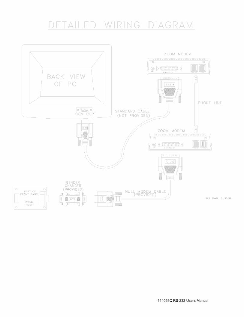
INTRODUCTION: This manual is intended to explain the operation and communication protocol for the “Series E”, “Series IE” and “Series EM” Emergency Lighting Central Inverter. Serial Communication can be established by means of a computer using Hyper-Link windows based software or using a Terminal device. CONNECTION: The Central Inverter has a 9 pin Sub-D Female connector located on the front panel located on the door of the inverter. See the Installation Guide for the exact location of the connector. The Connector between the computer and the Inverter is a straight connection. Do not use a Null Modem Cable that flips pins 2 and 3. Pin 2 and Pin 3 are the Data send and receive lines; Pin 5 is the Ground. Optical isolation on the Interface card provides galvanic isolation between the computers ground and the Inverters ground. PC Connector DB-9 “E”, “IE” and “EM” Central Inverter
Connector DB-9
Straight Connection Pins used = 2,3 5
Illustration 1 – Interconnect Schematic for RS-232 Connection Communication is established through a standard ASCII format of 8 Data bits, 1 Stop bit, No parity, No Flow Control, and a Baud rate of 19,200 BPS.
114063C RS-232 Users Manual
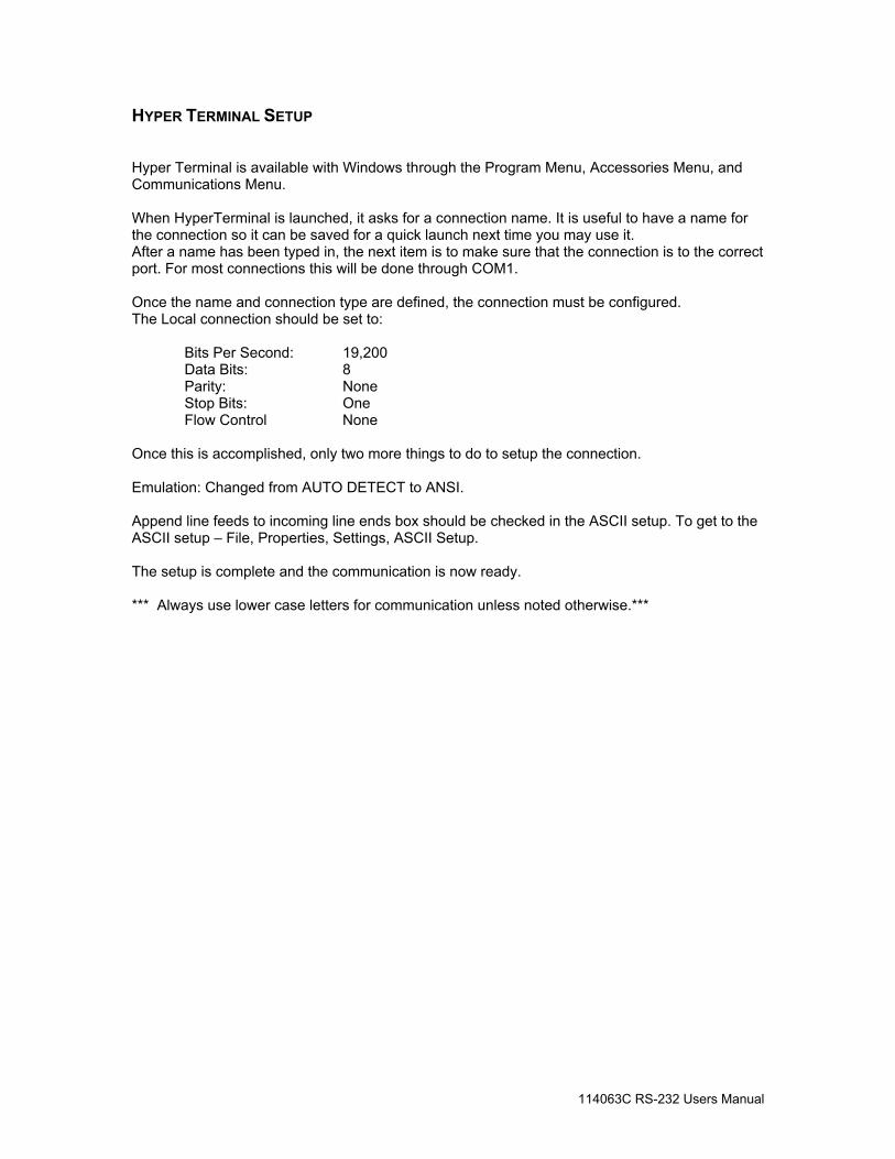
HYPER TERMINAL SETUP Hyper Terminal is available with Windows through the Program Menu, Accessories Menu, and Communications Menu. When HyperTerminal is launched, it asks for a connection name. It is useful to have a name for the connection so it can be saved for a quick launch next time you may use it. After a name has been typed in, the next item is to make sure that the connection is to the correct port. For most connections this will be done through COM1. Once the name and connection type are defined, the connection must be configured. The Local connection should be set to: Bits Per Second: 19,200 Data Bits: 8 Parity: None Stop Bits: One Flow Control None Once this is accomplished, only two more things to do to setup the connection. Emulation: Changed from AUTO DETECT to ANSI. Append line feeds to incoming line ends box should be checked in the ASCII setup. To get to the ASCII setup – File, Properties, Settings, ASCII Setup. The setup is complete and the communication is now ready. *** Always use lower case letters for communication unless noted otherwise.***

114063C RS-232 Users Manual
Shell Command The first command the PC needs to send to the interface is the shell command. The shell command acknowledges that the PC is connected. To execute the shell command type “shell” and press enter. Remember that lower case letters must be used. Upper Case characters are ignored!! During the shell command, there is no echo back of the characters as they are typed on the computer. If a typing error is made, when the “ENTER” key is pressed, the display will not change. The correct spelling of “shell” and the “ENTER” key must be executed correctly before the command prompt is displayed. Once the shell command is sent, the command prompt (CMD>) will appear at the hyper-terminal display screen. Once this command prompt (CMD>) appears, then the user can then query the machine. The command prompt. CMD> Once communication is established, all characters will be echoed back to the computer and the monitor will display what characters the user sends. Help screen Once the shell command is executed and the command prompt appears the user may type “help” for a listing of various commands available to the user. Now that communication is established, the characters will be echoed back to the display. So, when “help” is typed, “help” will be displayed. CMD>help ver Display current firmware version. fax Fax setup wizard. set point Display or modify set points. meter Display meter values. status Display present status. alarms Display alarms. dump Dump logs (alarms, tests, events). dt Display and change date-time setting. help List shell commands with brief descriptions. exit Exit from shell. Version The Revision level of the software is available by the “ver” command. CMD>ver

114063C RS-232 Users Manual
Fax Setup Wizard The fax modem option when purchased can be setup through the “fax” command. The information that can be entered through the setup wizard is the following points: CMD>fax Street Address City State ZIP Code Building Name Building Location Location within Building Emergency Contact Name Emergency Contact Phone# Unit Phone# User Defined 1 User Defined 2 User Defined 3 User Defined 4 User Defined 5 Inverter Fault faxes report : Disabled Charger Fault faxes report : Disabled Output Fault faxes report : Disabled Overload faxes report : Disabled Overload Shutdown faxes report : Disabled High Ambient faxes report : Disabled High VAC faxes report : Disabled Low VAC faxes report : Disabled Low Battery faxes report : Disabled Near Low Battery faxes report : Disabled Utility faxes report : Disabled Load Reduction faxes report : Disabled Runtime faxes report : Disabled Circuit Breaker faxes report : Disabled Overtemp faxes report : Disabled When a field is displayed, changes can be made. Once the changes are made, the interface sends back the changes. If the field data is correct, press “ENTER” and the next filed will be displayed.

114063C RS-232 Users Manual
Alarm Set point When the set point command is entered the following data is displayed: CMD>setpoint lvac: 108.0 off hvac: 132.0 off nlbatt: 111.0 off lbatt: 105.0 off htemp: 45.0 off lrc: 0.0 off lvac is the Low Voltage AC alarm, hvac is the High Voltage AC alarm, nlbatt is the Near Low Battery Voltage alarm, lbatt is the Low Battery Voltage Alarm, htemp is the High temperature alarm set point, and lrc is the Load Reduction Fault set point. To change the set points the tab must be used as the delimiter. To change the low voltage alarm to 105 VAC, type “lvac” and then tab and type”105” and then tab and then type “on” or “off” to turn the alarm on or off. Example: CMD>setpoint lvac 105 on Notice how there is a space between the word set point and lvac. The “TAB” character achieved this space. When the user presses “TAB”, a character is sent to the interface, this character inserts the space and also uses the “TAB” character as a delimiter between the data in the string. The other set points can be changed by the same manner. Meter Functions To read Voltages and currents, the meter command may be used. To use, type, “meter” and press enter. The following display will occur. CMD>meter vin: 118.3 vout: 118.3 iout: 12.3 vbatt: 54.1 ibatt: 0.1 tbatt: -61.1 tint: 29.8 imin: 0 days: 0 vaout: 1453.8 iwatts: 6.6

114063C RS-232 Users Manual
Status The statuses of the machine are accessible by typing “status” and enter. The following message occurs when status command is sent: CMD>status Battery Power: 0 Battery Charging: 1 Line Present: 1 System Ready: 1 Alarms The alarm status of the machine is available through the “alarms” command. When the alarm command is typed, the following information is available. CMD>alarms Inverter: 0 Charger: 0 Output: 0 Overload: 0 Overload Shutdown: 0 High Ambient: 0 High VAC: 0 Low VAC: 0 Low Battery: 0 Near Low Battery: 0 Utility: 0 Load Reduction: 0 Runtime: 0 Circuit Breaker: 0 Overtemp: 0 The format is binary. A “1” indicates that the alarm is present; a “0” indicates that no alarm is present. Alarms, Events, and Tests Dump The dump command displays all of the memory content for Events, Tests or Alarms. The dump command must be followed by a tab and then either alarms, tests or events as the second field. Example – Dump followed by tab and alarms would display all alarms stored in memory to date.

114063C RS-232 Users Manual
Date and Time The date and time can be viewed by typing the “dt” command. When dt is sent, the interface sends back the date and time information. Each parameter of the date and time are assigned a number. The dt command produces the following message: CMD>dt (1) day of week: 1..7 (2) month: 1..12 (3) day of month: 1..31 (4) year: 0..99 (5) hours: 0..23 (6) minutes: 0..59 TUE AUG 10, 2004 11:03:57 The Parameter day of week is 1 and its data is 1 through 7. 1 is Sunday, and then the days follow in sequential order. To change the parameter, type the dt command then the tab and then the parameter number and then the tab and then the parameter information. The tab is used as a delimiter between the commands and parameter number and parameter data. If the tab is not used, the command will be ignored and no change will be made.

114063C RS-232 Users Manual
CONFIGURING THE ZOOM MODEM (OPTIONAL) Connect the 9VDC Power Adapter Connect the PC serial port to the modem’s serial port On the PC, bring up a terminal communications program such as HyperTerminal. Configure HyperTerminal to the following:
19,200 BPS 8 Data Bits
No Parity No Stop Bits
No Flow Control Make sure there is communication by typing AT<enter> until the message “OK” appears. Type the following AT commands:
ATM1 <enter> (speaker on until connected) AT&D0 <enter> (ignore DTR)
AT&K0 <enter> (no flow control) ATS0=1 <enter> (auto-answer after one ring) AT&W0 (store to non-volatile memory)
DIALING THE ZOOM MODEM Type AT<enter> until the message “OK” appears Type for example:
ATD9, 16109545224 <enter> ATD is the command 9,16109545224 is the phone number –9, for outside line.
Wait for the message “connected” To hang up: Type three plus signs (+++) and wait for the message “OK” Type ATH0 <enter> to hang up or, Type ATO0 <enter> to enter online mode again

114063C RS-232 Users Manual
LOCATION OF THE RS232 PORT FOR “E” & “IE” 6-16.7k
LOCATION OF THE RS232 PORT FOR “E” & “IE” 1.5 –5.0k
PHONE LINE HOOKUP FOR E-MAIL MODEM OPTION.
PHONE LINE HOOKUP FOR E-MAIL MODEM OPTION.

114063C RS-232 Users Manual
LOCATION OF THE RS232 PORT FOR “EM” 1.0 – 2.8k
PHONE LINE HOOKUP FOR E-MAIL MODEM OPTION.
RS232 PORT BEHIND FRONT PANEL
114063C RS-232 Users Manual
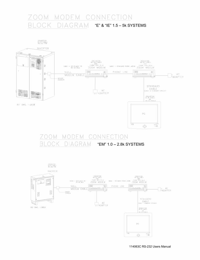
“E” & “IE” 1.5 – 5k SYSTEMS
“EM” 1.0 – 2.8k SYSTEMS
114063C RS-232 Users Manual