118 surface treatment engineering research and design ...€¦ · -max residual stress...
TRANSCRIPT

A critical evaluation of residual stresses in
spheroidal graphite cast iron due to mechanical
testing
HW Theunissen, D.G. Hattingh, J Maczek, A. Els-BotesDepartment of Mechanical Engineering, Port Elizabeth Technikon,Private BagX6011, Port Elizabeth, South AfricaEMail: [email protected]
Abstract
The understanding of the relationship between residual stresses and the effects ofmechanical testing on these stresses needs to be evaluated to develop a testingmethod to ensure the separation of Grey Cast Iron and Spheroidal Graphite (SG)Cast Iron for Automotive Safety Critical Components. Residual Stresses inmanufactured components are those stresses that exist without prior applicationof service or external loads'. Virtually all manufacturing and surface treatmentsinduce residual stresses into a component which may either be beneficial ordetrimental to the mechanical properties. This paper investigates the effect of anapplied load on the residual stresses within spheroidal graphite castings. In orderto measure the residual stresses present by means of the Centre Hole DrillingMethod, the locked-in stresses must be relieved by removing material to enable asensor to register the change in strain. In the final analysis the data will assistwith the development of a test specification whereby Safety Critical CastComponents can be load tested without inducing detrimental stresses into aspheroidal Graphite Casting, but would cause failure of a Grey Casting.
1 Introduction
Residual Stresses are internal stresses that are present in almost allcomponents that are manufactured, heat-treated or assembled. However, their
Transactions on Engineering Sciences vol 25, © 1999 WIT Press, www.witpress.com, ISSN 1743-3533

118 Surface Treatment
effects are often not evident until the component is subjected to an external loador exposed to an adverse environment. Residual Stresses are a phenomenon thathave been given many names and are receiving increased attention from theengineering research and design community. Many opportunities for theoptimisation of design and manufacturing parameters are directly dependent onthe better understanding of residual stresses".
This study of residual stresses in spheroidal graphite cast iron arosefrom a local foundry that established a need to develop a more reliable testprocedure for its Cast Safety Critical Automotive Components to compliment itscurrent ultra-sonic testing.
2 Test Method
The test requires the destruction of grey cast iron specimens, whichresult from inadequate inoculation, but induce no detrimental stresses into aspheroidal graphite cast iron specimen. This test would then eliminate the greycast iron components from the system and only allow SG specimens to proceedto the next phase of manufacture. The test to which the components weresubjected, was simply the application of a predetermined load at a specificlocation, as illustrated in figure 1, resulting in the destruction of the grey castiron specimens.
Figure 1: Arrows indicates the point of application of the strain gauges.(a) Shows the strain gauge and where the test load was applied(b) Shows the reference gauge for components CCC58/59
This investigation considered four components, each consisting of tenindividual specimens, five being right hand side and the other five being lefthand side automotive components. The test load for each of the components wasdetermined by performing destructive load tests on grey cast iron componentswith the same geometry as that of the SG cast iron components.
A 'before and after' residual stress measurement was taken at the area ofthe load application assessing any variation in the residual stress magnitude dueto the applied test load, see figure 1. However, due to the semi-destructivenature of the drilling method and the relaxing of the stresses around the hole due
Transactions on Engineering Sciences vol 25, © 1999 WIT Press, www.witpress.com, ISSN 1743-3533

Surface Treatment 119
to the drilling, the same specimen could not be used. To overcome this, anumber of specimens that were not subjected to the test load were used toestablish the residual stresses present. The components tested in thisinvestigation are listed in table 1.
ComponentMA 69MA 70CCC58CCC59
DescriptionRight Hand SideLeft Hand SideRight Hand SideLeft Hand Side
Test Load046 kN038 kN
Table 1: Test Components.
3 Residual Stress Measurement
The Automatic Centre Hole High Speed Drilling method of residualstress measurement was chosen over other methods because of its ability todetermine the residual stress distribution with depth, ease of operation and costeffectiveness. The evaluation software enables on-line measurement, while thechange-of-strain measurements, the principal stresses of the plane residual stressstate and their orientation can be viewed on the monitor in relation to the drilleddepth. The equipment also allows for a quick and accurate alignment of the endmill to the drilling location as well as easy measurement of the hole diameterafter drilling.
3.1 Description of Equipment and Drilling Procedure
The measurement of residual stresses require the internal stresses to berelieved by means of the destructive removal of successive layers of material.The equipment used was an Automatic Centre Hole Drilling device using a high-speed end mill is illustrated in figure2.
Figure 2: RESTAN Drilling Equipment.
Transactions on Engineering Sciences vol 25, © 1999 WIT Press, www.witpress.com, ISSN 1743-3533

120 Surface Treatment
The Residual Stress Equipment (RESTAN) consists of four major components:
3.1.1. Drilling DeviceThis drilling device houses an air turbine motor into which an inverted
end mill is taper locked. The turbine rotates at about 300 OOOrpm at a pressure of4.5 bar. To enable accurate alignment, the device consists of an optical aligningdevice to align the end mill to the centre of strain gauge's drilling location. Thehead is attached to the main frame via a V-slide and rack and pinion whichallows for the quick setting of the end mill to the strain gauge drilling location.The frame is controlled by a stepper motor, which allows for computercontrolled feed of the end mill through the centre of the strain gauge into thespecimen.
3.1.2. AmplifierThe amplifier that was used for the measurements was a MGC
amplifier, manufactured by HBM, which is computer controlled during thedrilling operation. The three gauge rosette was wired to the amplifier using afour-lead quarter bridge circuit and in conjunction with the amplifier, recordedthe strain magnitudes after each incremental step (cut).
3.1.3. Electronic DeviceThe function of the Electronic Device is to interface the computer
signals, the solenoid valve controlling the air supply to the turbine motor and thestepper motor.
3.1.4. Computer/SoftwareSINT Technology of Italy developed the software in collaboration with
HBM of Germany. This software controls the electronic unit and the MGCamplifier, as well as the processing of the strain data according to the number ofincremental steps when the drilling operation is completed.
3.1.5. Strain GaugesThe measurements were taken using a Micro-Measurements EA-06-
062RE-120 3-grid Rosette strain gauge as illustrated in figure 3.
Figure 3: Micro Measurement's EA-06-062RE-1203 grid Rosette Strain Gauge.
Transactions on Engineering Sciences vol 25, © 1999 WIT Press, www.witpress.com, ISSN 1743-3533

Surface Treatment 121
3.2 Measurement Procedure
The strain gauge was applied at the predetermined load point on eachsample. The three grids were connected to the MGC amplifier after which, theDrilling Device was positioned over the specimen and drilling head aligned andlevelled to the drilling location on the strain rosette. The feet of the DrillingDevice were secured to the worktable and the end mill was brought as close aspossible to the strain rosette and locked in this position as illustrated in figure 4.
Figure 4: Positioning of the Drilling Headon Strain Gauge Surface
The drilling parameters such as, number of incremental steps, depth aswell as the delay time (interval between cuts) were predetermined and enteredinto the software. After the gauges were zeroed, drilling commenced. The holeswere drilled to a depth of 2mm in 30 steps with the depths increasingincrementally from 0.01mm to 0.13mm. When the drilling was completed, theeccentricity of the hole was measured using the optical device in accordance withthe requirements set out in ASTM E837.94 (a). These measurements wereentered into the software for the final data processing of the strain resultscorresponding to their incremental depths.
3.3 Nomenclature
DZE
A ; B
a ; b
a
= hole diameter= gauge circle diameter= depth of hole= Young's modulus
= geometric constants as determined by ASTM 837.94(a)
= data reduction coefficients
= angle from the first principal strain from first strain gauge
Transactions on Engineering Sciences vol 25, © 1999 WIT Press, www.witpress.com, ISSN 1743-3533

122 Surface Treatment
Sgi Ey ;SG = relieved strains values, where a, b & c correspond with thegrids 1,2&3.
Gmax^min- maximum and minimum principal stresses
3.4 Calculation of Results
The principal stresses were determined according to the ASTM837.94(ar method of calculation.
Principal Stresses:
<TI & 0*2 = - " ±
Principal Angle:
tan 2a = — —
(1)
(2)
where: a - and: 6 = 2EB (3)
4 Results
Figure 5 illustrates the typical residual stresses present at full depth inloaded and unloaded specimens. This allowed for the establishment of a residualstress range for any specific set of components. The results for the unloaded andloaded specimens all fell within this range.
Residual Stress MA 69/70 (70 loaded to 46kN)
X X X X
Specimen Number
Figure 5: Range for Residual Stresses, Max -487MPa Min -72MPa
The hardness and residual stress results for two of the specimens testedare shown in figure 6. The graph illustrating the extreme (greatest maximum and
Transactions on Engineering Sciences vol 25, © 1999 WIT Press, www.witpress.com, ISSN 1743-3533

Surface Treatment 123
least maximum) residual stress results of these two specimens tested, while themean of the two is also plotted. It should be noted that specimen MA 70_2a,loaded to 46kN, produced the lowest residual stresses and specimen CCC 58_2a,which remained unloaded, produced the highest residual stresses.
No residual stresses were measured on grey castings, however theywere used to determine the test loads for SG castings.
Combined Mechanical Tests
(/)COQ)C-a03X
Q.
0.4 0.6 0.8 1 1.2 1.4 1.6 1.8 2 2.2 2.4 2.6 2.8 3 3.2 3.4 3.6 3.8 4
Depth from surface in mm
I Max Residual Stress (CCC58_2a)Mean Macro Hardness (CCC58_2a)Mean Macro Hardness (MA70_2a)
-Max Residual Stress (MA70_2a)-Mean Residual stressMicro Hardness (CCC58_2a)Micro Hardness (MA70_2a)
Figure 6: Combined Results showing the Micro and MacroHardnesses and the Extreme and Mean Residual Stresses.
Figure 7: SEM micrograph illustrating the fracture surface at 773x magnificationof Charpy Impact V-Notch test specimen with a 2319x magnification ofthe circled area.
Transactions on Engineering Sciences vol 25, © 1999 WIT Press, www.witpress.com, ISSN 1743-3533

124 Surface Treatment
Figure 7 shows the fracture modes of a ferritic ductile iron that wastested in a Charpy Impact Test at ambient temperature. The only modes offracture visible was ductile tearing and microvoid coalescence^. The dullfracture surface can be considered as a 100% shear surface according to ASTME23\ All the Impact specimens exhibited the same mechanical behaviour andfracture surface.
5 Discussion
The fundamental comparison in this investigation was betweenunloaded and loaded components and the result of these loads on the residualstresses, hardness and impact values.
The Macro hardness results were evaluated at three areas around thedrilled hole; on the surface, 2mm and 4mm below the surface, with four hardnessvalues taken at each level, as illustrated in figure 8. The average macro hardnessvalues at each depth was then plotted as illustrated on the hardness plot in figure6.
Figure 8: Area around the drilled hole where themacro and micro hardnesses were taken.
Ten micro hardness readings were also recorded at an average of 0.2mmfrom the edge of the hole and from a depth of 0.4mm to 4mm. Figure 6 indicatesthe mean micro hardness results projected to the surface.
It was observed that the average hardness for both the micro and macrohardness and for the loaded and unloaded specimens were all within 2% at adepth of 4mm while at 2mm there was an 8% difference between the twohardnesses. The graph in figure 6 indicates a steady decline in the macrohardness corresponding to the residual stresses with depth; it also depicts themicro hardness having a more rectilinear trend showing less change in hardnesswith depth next to the hole. This shows a constant hardness from the surface to4mm depth, confirmed by the final macro and micro hardness values beingwithin 3% of each other.
Transactions on Engineering Sciences vol 25, © 1999 WIT Press, www.witpress.com, ISSN 1743-3533
Surface Treatment 125
Examination of the !4 size Charpy Impact specimen fracture surfacesindicated that all the fractures exhibited a 100% shear surface according toASTM E23. The trend of Lateral Expansion showed a range of 0.36mm to0.52mm with an average of 0.46mm. The trend continued for the ImpactEnergy, having a minimum value of 8.5J and a maximum of 10J.
These results remained constant irrespective of the components beingsubjected to the test load or not.
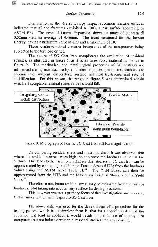
The nature of SG Cast Iron complicates the evaluation of residualstresses, as illustrated in figure 5, as it is an anisotropic material as shown infigure 9. The mechanical and metallurgical properties of SG castings areinfluenced during manufacture by a number of process parameters such as, thecooling rate, ambient temperature, surface and heat treatments and rate ofsolidification. For this reason, the range in figure 5 was determined withinwhich all acceptable residual stress values should fall.
Irregular graphitenodule distrbution
klands of Pearlitealong grain boundaries
Figure 9: Micrograph of Ferritic SG Cast Iron at 220x magnification
On comparing residual stress and macro hardness it was observed thatwhere the residual stresses were high, so too were the hardness values at thesurface. This leads to the assumption that residual stresses in SG cast iron can beapproximated by estimating the Ultimate Tensile Stress (UTS) from the hardnessvalues using the ASTM A370 Table 2B"\ The Yield Stress can then beapproximated from the UTS and the Maximum Residual Stress % 0.7 x YieldStress"".
Therefore a maximum residual stress may be estimated from the surfacehardness. Not taking into account any surface hardening processes.
This however was not a primary focus of this investigation and warrantsfurther investigation with respect to SG Cast Iron.
The above data was used for the development of a procedure for thetesting process which in its simplest form is, that for a specific casting, if thespecified test load is applied, it would result in the failure of a grey castcomponent but not induce detrimental residual stresses into a SG casting.
Transactions on Engineering Sciences vol 25, © 1999 WIT Press, www.witpress.com, ISSN 1743-3533

126 Surface Treatment
6 Conclusion
The results obtained for the loaded specimens fall within the typicalrange of residual stresses found in the unloaded specimens tested. Therefore, itcan be concluded that loading the components to their pre-determined test loadswill have no detrimental effect on the residual stresses in the SG Castings, butwould result in the failure/destruction of a grey casting. This was further provedby the tests carried out on the hardness and the Impact resistance of the testcomponents, which revealed negligible differences between loaded and unloadedcomponents.
Out of this investigation there has arisen a number of researchopportunities that could be addressed in the future, for example, the relationshipbetween residual stresses and surface hardness in SG Cast Iron.
7 Acknowledgements
1. National Research Foundation, Industrial Partner and the Port ElizabethTechnikon for their financial assistance.
2. Mr P McGrath, PE Technikon for technical assistance.3. Mr T Tonkin, for the manufacture of test specimens.4. Manufacturing Research Center, Port Elizabeth Technikon.
8 References
iReleigh, N.C. Measurement of Residual Stresses by the Hole-Drilling StrainGage Method, Tech Note TN-503-4, Measurements Group, 1993." Hattingh, D.G, du Preez, K.H. The analysis of process effects of55Cr3 springsteel on residual stresses and the relation to fatigue properties, SurfaceTreatment. Computational Mechanics Publications, 1997, p209-218"*Sines, G. Carlson, R. Hardness Measurement for Determination of ResidualStresses, ASTM Bulletin, 1952, p35-37"ASM Metals Handbook 9* edition, Fractography, vol 12, 1987Standard Methods for Notched Bar Impact Testing Metallic Materials, E23,Annual Book of ASTM Standards, July 1988.Standard Test Method for Determining Residual Stresses by Hole DrillingStrain-Gage Method, E837-94a, Annual Book of ASTM Standards, August1994.™Mordfin, L. Measurement of Residual Stresses: Problems and opportunities.National Bureau of Standards.
Transactions on Engineering Sciences vol 25, © 1999 WIT Press, www.witpress.com, ISSN 1743-3533