11th generation full high definition plasma display
DESCRIPTION
Panasonic Plasma Service ManualTRANSCRIPT

This Seminar covers the following models: TH-42PX80U, TH-50PX80U, TH-42PZ80U, TH-46PZ80U
TH-50PZ80U, TH-42PZ85U, TH-46PZ85U, and TH50PZ85U
11th Generation Full High Definition Plasma Display TV
National Training Panasonic Technology and Service Company

2
This page is purposely left blank.
2 Panasonic ideas for life

3
3 Panasonic ideas for life
Prepared byCesar Perdomo
Panasonic Service and Technology CompanyNational Training
Copyright ©
2008 by Panasonic Service and Technology CompanyAll rights reserved. Unauthorized copying and distribution is a violation of law.
WarningThis service information is designed for experienced repair technicians only and is not designed for use by the general public. It does not contain warnings or cautions to advise non-technical individuals of potential dangers in attempting to service a product. Products powered by electricity should be serviced or repaired only by experienced professional technicians. Any attempt to service or repair the product or products dealt with in this service information by anyone else could result in serious injury or death.
!

4
4 Panasonic ideas for life
Table Of ContentsSubject Page
Topics 5 Models Line-up (46” PDP TV Introduction for 2008) 6 Models Comparison 7 TH-XXPX80U TH-42PX80U Comparison to Last Year’s Models 8 Connectors Location (TH-42PX80U) 9 Power Supply/Signal Process/Panel Drive Circuit 10 -11 Power Supply (Standby) TH-42PX80U-TH50PX80U 12 Standby Operation 13 Connectors Location on the P board (TH-42PX80U) 14 Power On Operation TH-42PX80U-TH50PX80U 15 Power On Circuit Explanation 16 Voltages Distribution (TH-42PX80U) 17-18 TH-XXPZ80U and TH-XXPZ85U Boards Name and Function (TH-XXPZ80U/PZ85U) 20 Board Layout 21 TH-42PZ85U 22-23 TH-42PZ85U Connectors Location 24 TH-42PZ85U D Board and C Boards Location 25 Start-up Process 26-27 Start-up Process Block Diagram 28 Start up Process Description 29 Start up Process Description 30 Start-up Process Explanation 31 Sub-Voltages Distribution Block Diagram 32 Sub-Voltages Distribution Explanation 33 Troubleshooting 10 blinks Condition At Plug in (Schematic) 34 Troubleshooting 10 blinks Condition At Plug in 35 Power On Operation Block Diagram 37 The Power On Circuit Explanation 38 Voltages Distribution 39 Troubleshooting 10 blinks Condition Power On (Schematic) 40 Troubleshooting 10 blinks Condition Power On 41 Circuit Operation When A6 and A7 are Removed 43 Circuit Operation When A6 and A7 are Removed 44 Picture of connector A6 and A7 location 45 Power LED Blinking timing chart 47 D board SOS Detect 48
Subject Page D board SOS Detect (Explanation) 49-51 2 Blinks Error Code Block Diagram 52 Troubleshooting 2 Blinks Error Code 53 5 Blinks Error Code Block Diagram 54 Troubleshooting 5 Blinks Error Code 55 D16280(D280) Location (8 Blinks) 56 8 Blinks SOS Detect Circuit 57 Sustain Drive Board (SS) Isolation 58 Sustain Drive (SS) Board Isolation (Explanation) 59 SC/SU/SD Board Isolation (Explanation) 60 DRV Reset (6 Blinks) 61 Drive Reset Circuit Explanation 62 SU/SD Board Isolation (Pictorial) 63 SC/SU/SD Board Isolation (Explanation) 64 SC/SU/SD Board Isolation (Block Diagram) 65 Symptoms caused by defective SD boards 66 Symptom Caused By Defective SU Board 67 A board SOS Detect Block Diagram 68 A board SOS Detect (Explanation) 69 Digital Signal Processor Block Diagram (TH-42PZ85U) 71 Digital Signal Processor Explanation (TH-42PZ85U) 72 Switching to 4:3 to confirm problem with the A board 73 D Board (Format Converter/Plasma AI Processor) 74 Circuit Explanation 75-76 Pictures Of symptoms caused by the D board 77 Service Mode 79 Internal Test Patterns 80 Self Check 81 Check Point 82 Self Check Menu 83 How To Reset 84 Data Copy To SD Card 86-87 Data Copy From SD Card to The TV 88 How to Copy Self Check Data To SD Card 89-90 Software Upgrade 91-94 Picture Refresh 95-96 Extension Cable List 97-98 Extension Cable TH-XXPX80U (A Board) (P Board) 99-102

5
5 Panasonic ideas for life
Topics
Models Line-up (46” PDP TV Introduction for 2008)
HD Models/Full HD Models
Standby Operation
Power-on Operation
Shutdown Detect Circuit
Troubleshooting
Signal Process Circuit
Panel Drive Circuit
Adjustments
Service Notes

6
Models Line-up (46” PDP TV Introduction for 2008)
6 Panasonic ideas for life
2008 Panasonic PDP TV Series (11th Generation)
42” 46” 50” 58” 65”
HD TH-42PX80U (1 P Board) TH-50PX80U
(1 P Board)
FHD TH-42PZ80U (1 P Board)
TH-46PZ80U (2 P Boards)
TH-50PZ80U (2 P Boards)
FHD TH-42PZ85U (1 P Board)
TH-46PZ85U (2 P Boards)
TH-50PZ85U (2 P Boards)
FHD TH-42PZ800U (1 P Board)
TH-46PZ800U (2 P Boards)
TH-50PZ800U (2 P Boards)
TH-58PZ800U (2 P Boards)
FHD TH-46PZ850U TH-50PZ850U TH-58PZ850U TH-65PZ850U
Panasonic has introduced a 46” PDP TV for 2008
All the new 42” PDP TVs only have 1 “Power Supply” (P) board.
The 46”, 50”, and 58” models, with the exception of TH-50PX80U, have 2 “Power Supply” (P) boards.
These boards have different part numbers

7
2008 Models Comparison
7
HD FULL HD
Model TH-42PX80U TH-50PX80U
TH-42PZ80U TH-46PZ80U TH-50PZ80U
TH-42PZ85U TH-46PZ85U TH-50PZ85U
Resolution 1,024 by 768 (42”) 1,366 by 768 (50”) 1,920 by 1,080 1,920 by 1,080
PC Input 1
D Board Yes Yes
A Board Yes Yes Yes
Contrast Ratio 15,000:1 20,000:1 30,000:1
Panasonic ideas for life
Panel Life Expectancy = 100,000 HrsAltitude/Elevation Rating = 2800 Meter (9240 feet)

8
TH-42PX80U Comparison to Last Year’s Models
8 Panasonic ideas for life
The Models TH-42PX80U and TH-50PX80U do not have a D board. The circuits normally found in the D board on previous models, are now built into the A board.
TH-42PX75U (2007 Model) TH-42PX80U (2008 Model)
D Board
No D Board

9
Connectors Location (TH-42PX80U)
9 Panasonic ideas for lifeThis slide shows the location of the connectors on all the boards

10
Power Supply/Signal Process/Panel Drive Circuit
10 Panasonic ideas for life
TH-42PX80U

11
Power Supply/Signal Process/Panel Drive Circuit
11 Panasonic ideas for life
The PDP TV consists of several circuits.
The Power Supply:
This circuit provides the voltages necessary to drive all the circuits in the TV.
Signal Processing/CPU:
This circuit is designed to perform all the functions necessary to process any input signal.
The CPU provides commands to turn on the TV. It communicates with other components on the TV via the bus line. It also provides protection by monitoring the supply voltages for abnormalities.
Panel Drive Circuit:
This circuit provides the control drive pulses to the drive circuit boards to drive the panel.
12
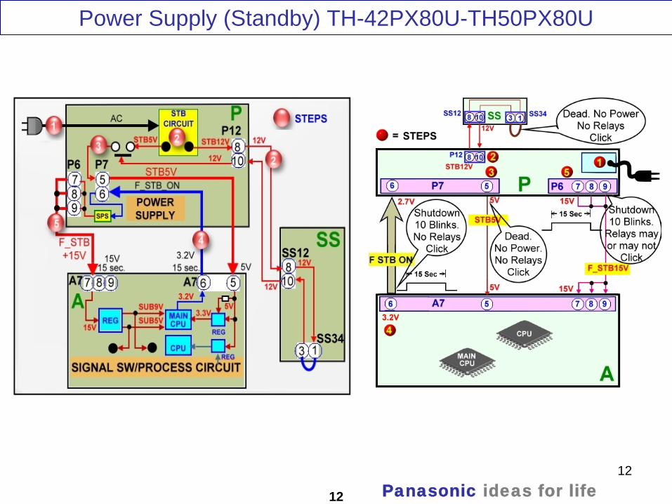
Power Supply (Standby) TH-42PX80U-TH50PX80U
12 Panasonic ideas for life

13
Standby Operation
13 Panasonic ideas for life
When the TV is plugged in:
AC is applied to the standby circuit in the power supply to produce STB12V and STB5V.
The STB12V is routed thru the SS board and it’s returned back to the P board to turn on a switching circuit that outputs the STB5V. If the STB5V is missing, the TV is dead (No power)
The STB5V is output from the P board at pin 5 of connector P7 and it is applied to pin 5 of connector A7 on the A board.
The STB5V is applied to a 3.3V regulator to power the Main CPU (IC1100) on the A board.
When the Main CPU (IC1100) receives 3.3V, it outputs a temporary 2.7V/3.2V command that is provided to pin 6 of connector P7 on the P board. The function of this command is to turn on the circuit that generates the “F+15V” in the P board.
The P board outputs the F+15V to pins 7, 8, and 9 of connector A7 in the A board. This voltage is applied to a regulator circuit that generates: SUB9V, SUB5V, and SUB3.V.If any of these voltages (F+15V, SUB9V, SUB5V, and SUB3.3V) are missing, the TV shuts down and the power LED blinks 10 times.

14
Connectors Location on the P board (TH-42PX80U)
14 Panasonic ideas for life
This picture shows the location of the connectors on the P board

15
Power On Operation TH-42PX80U-TH50PX80U
15 Panasonic ideas for life

16
Power On Circuit Explanation
16 Panasonic ideas for life
1. The power command from the power switch on the S board or the remote control receiver on the K board is provided to the Main CPU on the A board thru connector A1. The CPU on the A board outputs the “F_STB_ON” Command and the PANEL_STB_ON” command.
2. The “F_STB_ON” command is provided to pin 6 of connector P7 of the power supply to develop the F_STB+15V.
3. The “PANEL_STB_ON” is used to turn on the STB3.3V regulator on the A board. The output voltage is applied to the “Panel” CPU on the A board (Formerly located in the D board).
4. When the “Panel” CPU on the A board is energized, it outputs the “PANEL_MAIN_ON” Command (3.2V) to pin 11 of connector P25 on the P board.The PANEL MAIN ON command turns on the power supply circuit that outputs the Vsus, Vda, 15V, and 5V.

17
Voltages Distribution (TH-42PX80U)
17 Panasonic ideas for life

18
Voltages Distribution (TH-42PX80U)
18 Panasonic ideas for life

19
19 Panasonic ideas for life
TH-XXPZ80U and TH-XXPZ85U
Because of the similarities between the TH-XXPX80U, the TH-XXPZ80U, and TH-XXPZ85U, from this point forward, the material used in the guide is based on the TH-XXPZ85U.

20
Boards Name and Function (TH-XXPZ80U/PZ85U)
20
Board Name Function Board Name Function
P Power Supply D Format Converter, Plasma AI, Sub-Field Processor
PB Fan control C1 Data Driver (Upper Right) A Speaker out, Sound Processor AV Terminal,
AV Switch C2 Data Driver (Upper Left)
DC-DC Converter Digital Signal Processor, Microcomputer HDMI Interface, Peaks Lite 2, Full HD
SC Scan Drive G Front terminal, AV3, Key Switch SU Scan out (Upper) K Remote receiver, Power LED SD Scan out (Lower) S Power Switch SS Sustain Drive
GS SD Card Slot GH HDMI3 in
Panasonic ideas for life

21
21
Panasonic has been using single scan addressing in our standard definition (SD) Plasma TVs for a while now. In 2006 (9th generation), Panasonic started using single scan addressing in our 42” HD models.In 2007 (10th generation), the 50” HD models were added to the list of TV using single scan addressing.For 2008 (11th generation), the 42” and 50” (Not yet confirmed in 58” and 65”) Full HD models (PZ80, PZ85, and PZ800 (Not yet confirmed in PZ850) were also added to the list.
Board Layout
Panasonic ideas for life

22
TH-42PZ85U
22 Panasonic ideas for lifeThis is a picture of the TV with the rear cover removed

23
TH-42PZ85U Pictorial Boards Layout
23
In this line of Full HD Plasma TVs, the number of boards used have been reduced. Both the DG board and the H board are no longer used. The circuits found in these boards are now part of the A board.
Panasonic ideas for life
24
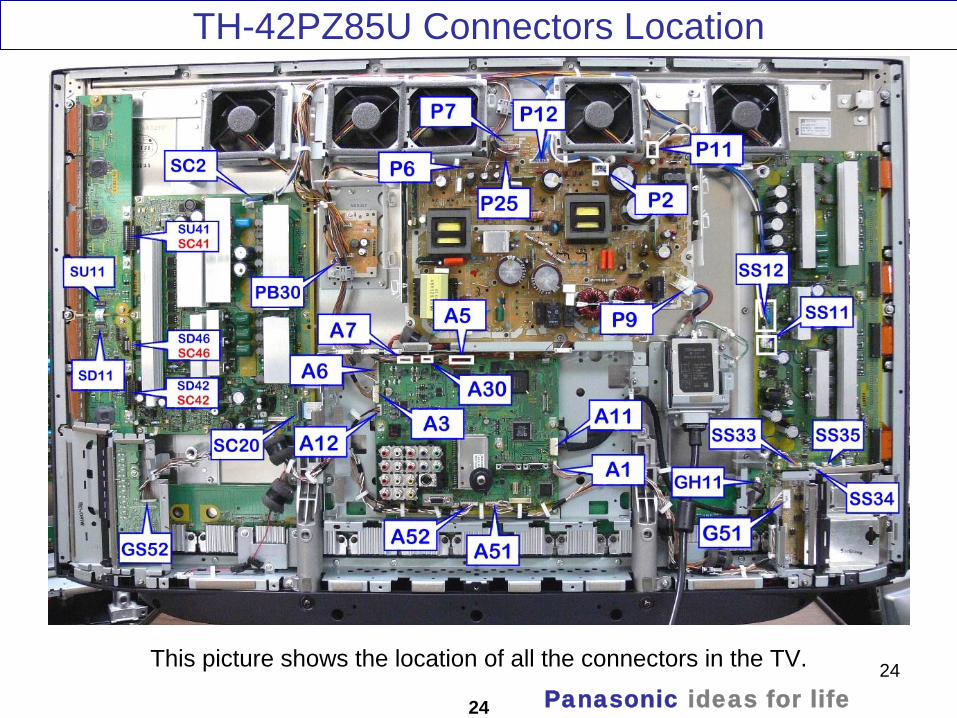
TH-42PZ85U Connectors Location
24
This picture shows the location of all the connectors in the TV.
Panasonic ideas for life

25
TH-42PZ85U D Board and C Boards Location
25
This picture shows the location of the D board and its connectors.
Panasonic ideas for life
26
Start-up Process
26 Panasonic ideas for life

27
27
Upon connecting the Panasonic Plasma Display Television to the AC line, the sound of relays being triggered can be heard from the Power Supply board. Also a red light from the Optical jack on the back of the TV can be observed.
Approximately 15 seconds later, the click sound from the relays can be heard again and the red LED inside the Optical jack turns off.
This condition is normal and by paying attention to this sequence of events, we can confirm the operation of several circuits inside the TV.
Start-up Process
Panasonic ideas for life

28
Start-up Process Block Diagram
28
STB3.3V
Panasonic ideas for life

29
Start up Process Description
29
When the TV is plugged in:AC is applied to the power supply board (P) through connector P9. The ACis applied to the standby circuit to produce STB12V and STB5V.
The STB5V is routed thru the SS board to turn on a circuit which function is to allow theoutput of the STB5V through connector P7.
The STB5V is output from the P board at pin 5 of connector P7 and it is applied to pin 5 of connector A7 on the A board.
The STB5V is applied to a 3.3V regulator to power the Main CPU (IC1100) on the A board. The 3.3V becomes STB3.3V.
The STB3.3V is applied to the power LED and the remote control receiver in the K board.
When the Main CPU (IC1100) receives 3.3V, it outputs a 2.7V command that is provided to the P board and the SOS Detect circuit within the A board. This command only lasts approximately 15 seconds and it is called “F-STB-ON”. The function of this command is to turn on the circuit that generates the “F-STB-14V” in the P board.
The function of the 2.7V command applied to the SOS Detect circuit in the A board together with the STB5V, is to activate the “SOS DETECT” circuit in the A board.
The F+15V from connector P6 on the P board is applied to connector A6 in the A board. This voltage is applied to a regulator circuit that generates: SUB9V, SUB5V, and SUB3.V.
Panasonic ideas for life

30
30
Start-up Process (Detailed Circuit)This is a detailed block diagram of the start up process
Panasonic ideas for life
31
Start-up Process Explanation
31
When AC is applied to the TV, the Standby circuit outputs 5Vdc and 12Vdc. The 5V is applied to the Power CPU and a switching IC MC552 on the power supply circuit. The 5V is also provided to the SS board. A jumper at connector SS34 of the SS board routes the 5V back into the power supply board to turn on the switching circuit inside the CPU MC701. When this circuit is on, MC552 turns on and the STB5V is output to the A and D boards. The STB5V is output to the A Boards thru pin 5 of connector P7.The STB5V is applied to a 3.3V regulator (IC4000) on the A board to provide the supply voltage (STB3.3V) to the Main CPU (IC1100).
The STB3.3V is also applied the Remote Control receiver and the power LED on the K board.
When the Main CPU IC1100 on the A board receives the 3.3V, it outputs the SUB_ON/TUNER_SUB_ON command (2.7V) to the Power MCU (MC701) located on the Power Supply board.
The power supply MCU outputs commands to turn on the circuits necessary to generate the F+15V.
The F+15V from the P board is applied to the 5V/9V regulators, IC5400 and IC5401on the A board. The voltage outputs from these ICs are called SUB5V and SUB9V and are used by various circuits on the A board. To avoid catastrophic failures, they are monitored by an SOS Detect circuit for over-voltage and over-current conditions. This SOS Detect circuit is controlled by the TUNER_SUB_ON command from the Main CPU (IC1100). The SUB5V and SUB9V from IC5400 and IC5401 are connected to the CPU for voltage presence detection.
Any abnormalities of the SUB5V or SUB9V triggers the SOS circuit. The TV shuts down and the power LED blinks 10 times. This happens while the TV is off (Before turning on the power).
Panasonic ideas for life

32
Sub-Voltages Distribution
32 Panasonic ideas for life

33
Sub-Voltages Distribution
33
• The F+15V from the P board is the source that supplies the DC-DC converter (IC5400 and IC5401) in the A board. The A board outputs 9V, 5V, and 3.3V.
• The 9V is only used by the A board.• The 5V, besides being used in the A board, is also distributed to the K and GH boards.• The 3.3V is used in the A board and it’s also provided to the GH and GS boards.• A 10 blinks code from the power LED indicates abnormalities on any of these voltages.
Panasonic ideas for life
34
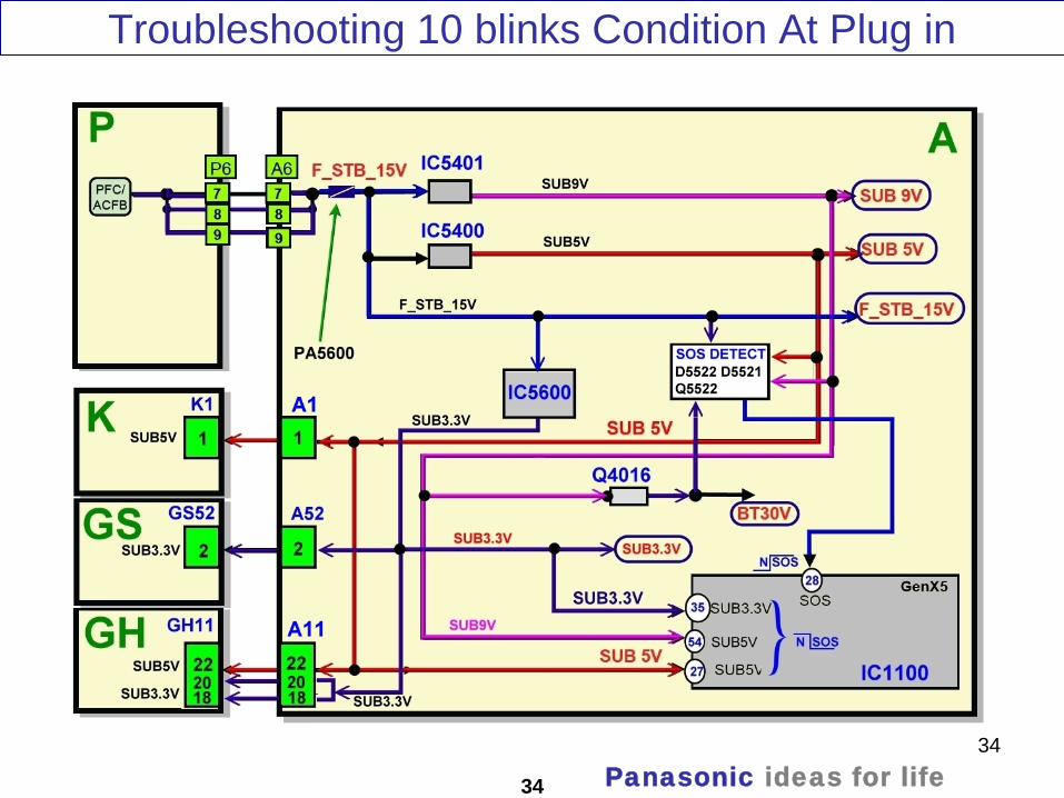
Troubleshooting 10 blinks Condition At Plug in
34 Panasonic ideas for life

35
Troubleshooting 10 blinks Condition At Plug in
35 Panasonic ideas for life
1. Missing/Shorted F_STB_15V
2. Missing/Shorted SUB9V, SUB5V, and SUB3.3V
3. Wrong diagnostic by the A board
These 3 conditions can cause the TV to shutdown and the power LED to blink 10 times
To troubleshoot a PDP TV that is shutting down and the power LED blinks 10 times:
Find out if 15V is output at pin 7,8,or 9 of connector P6 of the P board. If no voltage is output,
the P board may be defective.
If the F_STB_15V voltage is OK, it’s likely that the A board is defective.
Since some of the Sub-voltages generated by the A board are connected to the K, GS, and
GH boards, it’s also likely that one of these board may cause the unit to shut down and the
power LED to blink 10 times.
Disconnect connector A1/K1 to isolate the K board.
Disconnect connector A/52GS52 to isolate the GS board.
Disconnect connector A11/GH11 to isolate the GH board.
The defective board is found when the connector that provides the Sub-voltages to that board
is removed and the TV no longer shuts down.
Note: When taking voltage reading, place the voltmeter probe at the test point, component, or connector’s pin indicated before connecting the TV to the AC line. This will ensure voltage reading accuracy before the TV shuts down.
36
Power On Operation
36 Panasonic ideas for life
37
Power On Operation
37
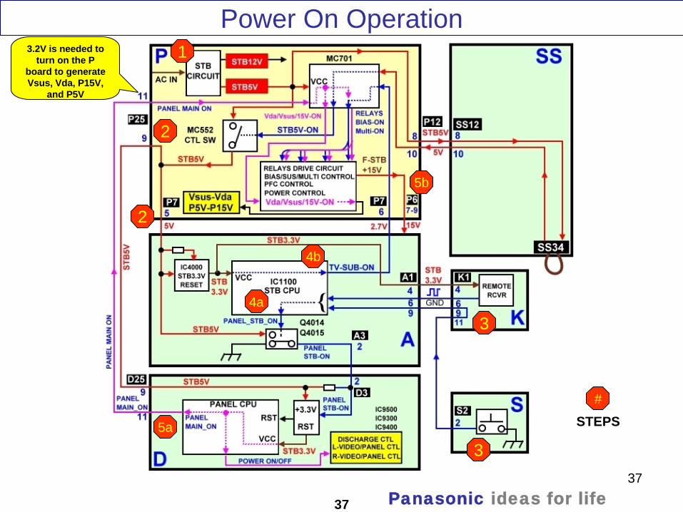
3.2V is needed to turn on the P
board to generate Vsus, Vda, P15V,
and P5V
1
2
2
3
34a
4b
5a
5b
#
STEPS
Panasonic ideas for life

38
The Power On Circuit Explanation
38
The power command from the power switch on the S board or the remote control receiver on the K board is provided to the CPU in the A board.
The CPU on the A board outputs the “PANEL_STB_ON” command and the “F_STB_ON” command.
The “PANEL_STB_ON” is provided to the D board to turn on the STB3.3V regulator. The output voltage is applied to the CPU in the D board.
The “F_STB_ON” command is provided to the power supply to develop the F_STB+15V.
When the CPU on the D board is energized, it outputs the “PANEL_MAIN_ON” and the “POWER ON/OFF Commands.The PANEL MAIN ON command turns on the power supply circuit that outputs the Vsus, Vda, 15V, and 5V.
The POWER ON/OFF command turns on the Video/Panel Control and the Discharge Control circuits in the D board.
Panasonic ideas for life

39
Voltages Distribution
39 Panasonic ideas for life

40
Troubleshooting 10 blinks Condition At Power On
40 Panasonic ideas for life

41
Troubleshooting 10 blinks Condition At Power On
41 Panasonic ideas for life
1. Missing/Shorted F_STB_15V
2. Shorted P15V
3. Missing/Shorted SUB9V, SUB5V, and SUB3.3V
4. Missing Vda (Shorted Vda causes 5 blinks)
5. Wrong diagnostic by the A board
These 5 conditions can cause the TV to shutdown and the power LED to blink 10 times
To troubleshoot a PDP TV that is shutting down and the power LED blinks 10 times:
Isolate the SC and the SS boards (They may cause a 10 blinks shutdown). Disconnecting P6
and P7 allows for only the panel drive section to be driven. If the LED on the SS board and
the LED on the SC board are lid, then the SS and the SC boards are OK and the A board is
suspected to be defective
If the LEDs on the SS and SC boards are not lid, then isolate them one at time.
If the SS and SC boards are OK, then the P board may be defective.
Note: The P15V and the F_STB_15V are created by the same circuit in the power supply circuit. A shorted P15V, normally causes the TV to shut down and the power LED to blink 2 times.
Sometimes a shorted P15V affects the F_STB_15V and this causes the TV to shutdown making the power LED blink 10 times.

42
Circuit Operation When Connectors A6 and A7 are Removed
42 Panasonic ideas for life

43
Circuit Operation When A6 and A7 are Removed
43
3.2V is needed to turn on the P board to generate Vsus, Vda, F_STB15V, P15V, and P5V
2.7V is needed to turn on the P
board to generate just the F_STB15V
The A, K, GH, and S board are disabled when A6 and A7 are disconnected
If STB5V is not provided to the A board, the CPU is
disabled
IC9003
Panasonic ideas for life

44
44
The result obtained on previous generations when D3 was disconnected, can now be obtained by disconnecting A6/P6 and A7/P7.
When these connectors are removed, the A, K, GH, and S boards are disabled.
Normally Pin 2 of connector A3 is grounded by Q4014-Q4015. When A6 and A7 are disconnected pin 2 is no longer grounded. This allows for the 3.3V regulator on the D board to output 3.3V to the Panel CPU (IC9003).
The Panel CPU (IC9003) outputs a command that is provided to 2 different circuits.
The “Panel Main On” command (3.2V) is connected to pin 11 of connector P25 on the power supply turning on the circuit that generates Vsus, Vda, P15V, and P5V.
The “Power On/Off” command (3.2) is connected to the Video/Panel Control and Discharge circuit to output the panel drive control pulses.
This method of isolation is useful when troubleshooting problems where the A, GH, K, or S board are suspected to be defective.
Circuit Operation When A6 and A7 are Removed
Panasonic ideas for life

45
Connector A6 and A7 location
45
It may not be necessary to remove the metal plate in front of the input jacks when disconnecting connectors A6 and A7. To remove the metal plate in front of the input jacks, remove the 6 screws shown on Figure 1.
Figure 1
Figure 2
Panasonic ideas for life
46
46
When an abnormality occurs in the unit, the “SOS Detect” circuit is triggered and the TV shuts down. The power LED on the front panel will flash a pattern indicating the circuit that has failed.
SOS DETECT (SHUTDOWN)
Panasonic ideas for life

47
Number of blinks Contents Check point
1 Communication Error with
Microcomputer
D, A
2 15V SOS D
3 3.3V SOS D
4 Power Supply SOS P
5 5V SOS D
6 SC Energy recovery SOS
SC, SU, SD, D, P
7 SC floating voltage SOS
SC, SU, SD, D, P
8 SS Energy recovery SOS
SS, D, P
9 Panel Configuration SOS D
10 Sub 5V SOS, Main 3.3V SOS, DTV9V
SOS, Tuner SOS
A
12 Sound SOS A
13 Communication Error with Peaks
Lite-2
A
Power LED Blinking timing chart
47 Panasonic ideas for life

48
D board SOS Detect
48 Panasonic ideas for life

49
D board SOS Detect
49
• Protection circuits are incorporated in the unit to prevent the failure of a single circuit or component from creating catastrophic damage.
• A shutdown condition occurs when there is an over voltage, a short or a drop in any of the voltage lines. Also the shutdown circuit is triggered when the fans are drawing more current than normal.
• Normally the CPU of the D board and the CPU of the A board detect when a shutdown condition has been triggered.
• When an abnormality has occurred, the unit protection circuit operates and the TV is reset to the stand-by mode. At this time, the defective block can be identified by the number of blinks of the POWER LED on the front of the unit.
• IC9003 of the D board detects conditions that make the power LED blinks 2, 3, 4, 5, 6, 7, 8, or 9 times.
• The following table identifies the areas where a problem is suspected according to the number of times that the POWER LED blinks.
• 2 Blinks SOS: Pin 62 of the CPU IC9003 monitors the 15V line. During normal operation pin 62 is kept high. If the 15V line is missing or shorted, a low is provided to pin 62. As a result, the unit shuts down and the power LED blinks 2 times.
• 3 Blinks SOS: IC9805 is a 3.3V regulator located on the D board. Its output is monitored by IC9003. If the 3.3V is not present at pin 61, the CPU (IC9003) shuts down the unit. The power LED blinks 3 times.
Panasonic ideas for life

50
D board SOS Detect
50
• 4 Blinks SOS: When an over voltage condition of the voltage lines from the power supply occurs, pin 18 of MC701 goes high. This high is provided to pin 67 of IC9003 of the D board triggering the “POWER SOS” circuit. When this happens, the TV shuts down and the power LED blinks 4 times. Primarily the P board causes 4 blinks, followed by the D board.
• 5 Blinks SOS: Pin 60 of the CPU IC9003 monitors the 5V line. During normal operation, pin 60 is kept high. If the 5V line is missing or shorted, a low is provided to pin 60. As a result, the unit shuts down and the power LED blinks 5 times.
• 6 Blinks SOS: Pin 65 of the CPU IC9003 monitors the status of the SC board. During normal operation, a low is applied to pin 65. If the SC board becomes defective, a high is provided to pin 65. As a result, the unit shuts down and the power LED blinks 6 times.
• 7 Blinks SOS: Pin 68 of the CPU IC9003 monitors the status of the SC, SU, SD board. During normal operation, a low is applied to pin 76. If the SC, SU, or SD board becomes defective, a high is provided to pin 68. As a result, the unit shuts down and the power LED blinks 7 times.
• 8 Blinks SOS: Pin 66 of the MPU IC9003 monitors the status of the SS board. During normal operation, pin 8 of connector SS33 outputs a low to pin 66. If the SS board becomes defective, a high is provided to pin 66. As a result, the unit shuts down and the power LED blinks 8 times.
Panasonic ideas for life

51
D board SOS Detect
51
• A defective D board may also be responsible for the 2, 3, 4, 5, 6, 7, 8, or 9 blinks of the power LED. A defective component on the D board may supply the MPU (IC9003) an erroneous input that causes the unit to shut down, with the power LED blinking a number of times.
Panasonic ideas for life

52
2 Blinks Error Code
52 Panasonic ideas for life
1. Missing P15V
2. A short of the P15V
3. Wrong diagnostic by the D board
These 3 conditions can cause the TV to shutdown and the power LED to blink 2 times
P15V Distribution
53
Troubleshooting 2 Blinks Error Code
53 Panasonic ideas for life
When troubleshooting a PDP TV that is shutting down and the power LED blinks 2 times:
Find out if 15V is output at pin 1 of connector P7 of the P board.
If no voltage is output, measure resistance between pin 1 of connector P7 and ground (Chassis). If a shorted 15V is detected, find out if it’s coming from the P board or if it’s coming from any of the other boards that the 15V volt is connected to.
If the P board is OK, disconnect the connectors providing the P15V to all these boards while measuring resistance between pin 1 of connector P7 and ground.
The defective board is found when the connector that provides the P15V to that board is removed and the short circuit is no-longer present.

54
5 Blinks Error Code
54 Panasonic ideas for life
1. Missing P5V
2. A short of the P5V
3. A short of the Vda line (Note: missing Vda from the P board does not cause 5 blinks)
4. Wrong diagnostic by the D board
These 4 conditions can cause the TV to shutdown and the power LED to blink 2 times
P5V and Vda Distribution
55
Troubleshooting 5 Blinks Error Code
55 Panasonic ideas for life
When troubleshooting a PDP TV that is shutting down and the power LED blinks 5 times:
Find out if pin 1 of connector P12 is shorted to ground. If it is, possibly the panel is bad. If there is no short circuit, proceed to check the P5V line.
Find out if 5V is output at pin 5 of connector P25 of the P board.
If no voltage is output, measure resistance between pin 5 of connector P25 and ground (Chassis). If a shorted 5V is detected, find out if it’s created on the P board or if it’s created on any of the other boards that the 5V volt is connected to.
If the P board is OK, disconnect the connectors providing the P5V to all these boards while measuring resistance between pin 5 of connector P25 and ground.
The defective board is found when the connector that provides the P15V to that board is removed and the short circuit is no-longer present.

56
56
D16280(D280) Location (8 Blinks)
Anode
D16280(D280)
PANEL
TH-42PZ85U
To pin 66 IC9003
N 2.7V SOS
Panasonic ideas for life
57
8 Blinks SOS Detect Circuit
57
There is an extra SOS Detect circuit in the Sustain board. This circuit is used to monitors for short circuit condition of the sustain electrodes in the panel. Under normal condition, D16282 conducts keeping Q16280 on. When Q16280 is on, a low is provided to the anode of D16280 (D280).If a short circuit is detected, Q16280 turns off and a high is provided to the anode of D16280 (D280). This high is provided to pin 66 of the CPU in the D board. When this happens, the TV shuts down and the power LED blinks 8 times.To determine if the 8 blinks is caused by the D board, SS board, or the
Panel:• Isolate the SS board and check if the TV stays on when it’s turned on.• If the TV does not stay on after disconnecting the SS board, the D board
is defective.
• If the TV stays on, then the SS or the Panel is defective. • If the anode of D16280 (D280) is high (2.7V) at the time the unit shuts down, the Panel is defective.
• If the anode is low, the SS board is defective.
Panasonic ideas for life
58
Sustain Drive Board (SS) Isolation
58
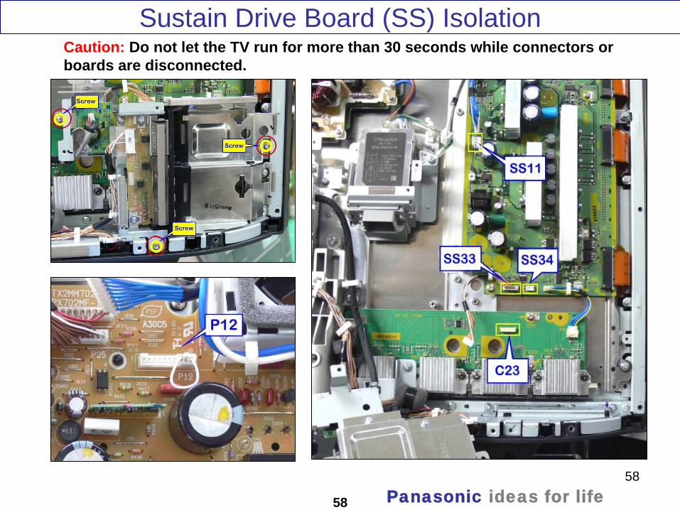
Caution: Do not let the TV run for more than 30 seconds while connectors or boards are disconnected.
Panasonic ideas for life
59
59
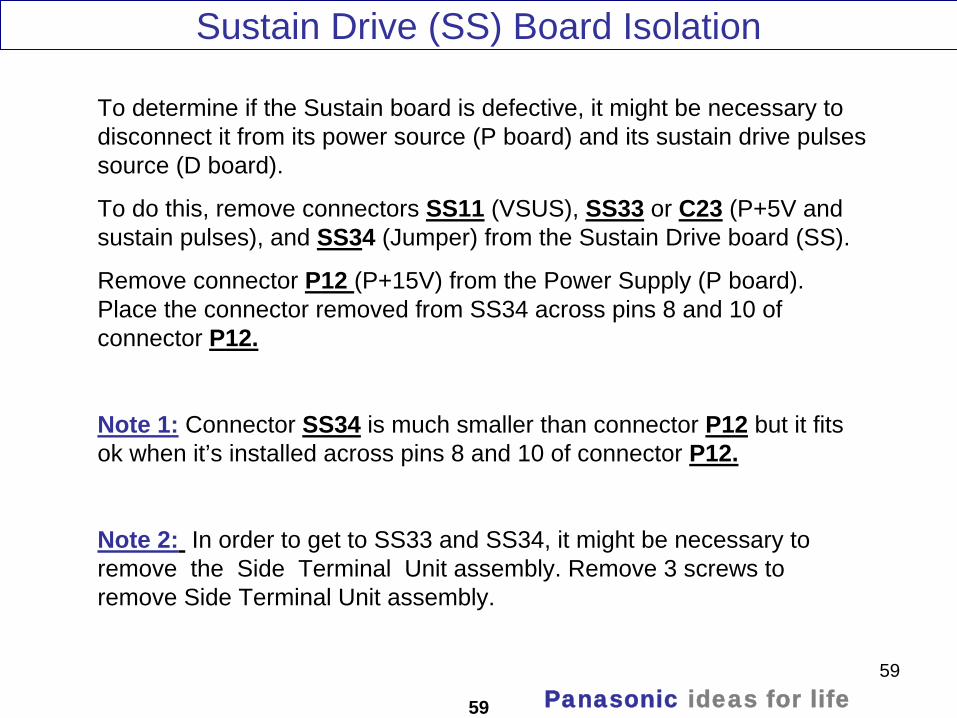
Sustain Drive (SS) Board Isolation
To determine if the Sustain board is defective, it might be necessary to disconnect it from its power source (P board) and its sustain drive pulses source (D board).
To do this, remove connectors SS11 (VSUS), SS33 or C23 (P+5V and sustain pulses), and SS34 (Jumper) from the Sustain Drive board (SS).
Remove connector P12 (P+15V) from the Power Supply (P board). Place the connector removed from SS34 across pins 8 and 10 of connector P12.
Note 1: Connector SS34 is much smaller than connector P12 but it fits ok when it’s installed across pins 8 and 10 of connector P12.
Note 2: In order to get to SS33 and SS34, it might be necessary to remove the Side Terminal Unit assembly. Remove 3 screws to remove Side Terminal Unit assembly.
Panasonic ideas for life

60
60
SC/SU/SD Board IsolationTo isolate the Scan Drive Section (SC, SU, and SD board), remove connectors SC2 (Vsus) and SC20 (P+15V, P+5V, and Scan pulses) from the SC board.
When this is done, the display is completely black (No picture)
Caution: Do not let the TV run for more than 30 seconds while connectors or boards are disconnected.
This procedure could be useful when troubleshooting 7 blinks problems.
Panasonic ideas for life

61
DRV Reset (6 Blinks)
61 Panasonic ideas for life

62
Drive Reset Circuit Explanation
62
The DRV RST circuit of the D board is used to monitor the physical connection of the D board to the C board. DRV RST input to IC9500 and IC9003 must be high for the unit to operate. The D board provides the 5V source needed to power the C boards. On the C1 board and the C2 board, the 5V is routed back to the D board via connector C11/D31, C21/D33 to activate the 5V SENSE circuit. A voltage divider consisting of R9157 and R9162 (For TH-42PZ85U) develops a voltage drop that causes the collector of transistors Q9058, Q9059, and Q9060 to become low. As a result, the base voltage of Q9061 also becomes low causing its collector to go high. The output voltage is applied to IC9500 and IC9003 as DVR RST.
When the 5V SENSE circuit does not detect 5V from the C1 board and the C2 board, the DVR RST output becomes low. The unit goes into shutdown and the power LED blinks 6 times.
Panasonic ideas for life

63
63
Caution: Pay close attention to the VF Ground Screws.Resistance between VF ground and Chassis ground should be in the Kilo-ohms range
SU/SD Board Isolation
Panasonic ideas for life

64
64
SC/SU/SD Board Isolation (Explanation)
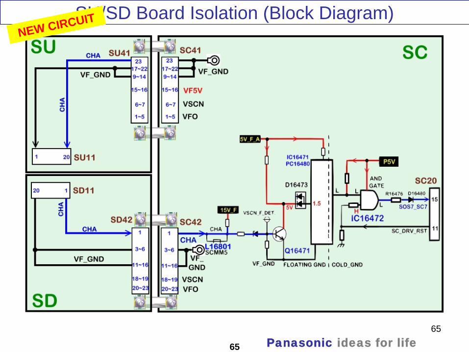
Unlike previous models of Panasonic Plasma TVs, the 2008 models are designed not to turn-on if either the SU or SD board is disconnected.
Disconnecting either causes the unit to shutdown and the power LED to blink 7 times.
Unplugging any of the connectors SC41/SU41, SU11/SD11, andSC42/SD42, opens the interlocked connection between VF_GND and CHA on the SC board. This floats point “CHA” and Q16471 turns on. IC16471 and PC16480 output a high to the “And” gate (IC16472) triggering shutdown.
Panasonic ideas for life
65
65
SU/SD Board Isolation (Block Diagram)NEW CIRCUIT
Panasonic ideas for life
66
66
Symptoms caused by defective SD boards
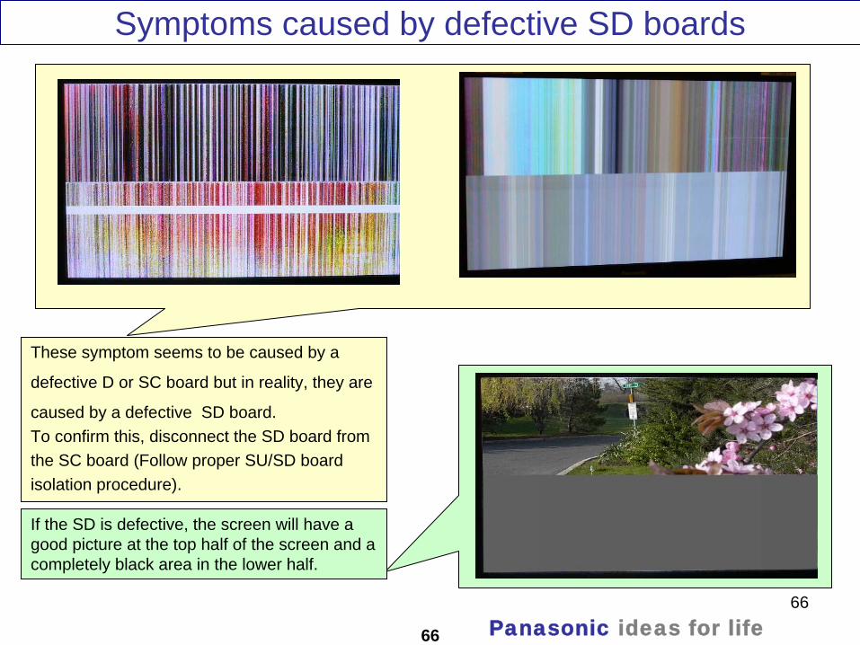
These symptom seems to be caused by a
defective D or SC board but in reality, they are
caused by a defective SD board.To confirm this, disconnect the SD board from the SC board (Follow proper SU/SD board isolation procedure).
If the SD is defective, the screen will have a good picture at the top half of the screen and a completely black area in the lower half.
Panasonic ideas for life

67
Disconnect the SU board from the SC board. (Follow proper SU/SD board isolation procedure) If the SU is defective, the screen will have a good picture at the bottom half of the screen and a completely black area in the upper half.
67
Symptom Caused By Defective SU Board
This is what normally a non shutdown problem caused by the SU board looks like
Panasonic ideas for life

68
A board SOS Detect Block Diagram
68
If a fan is disconnected, place a jumper between pin 2
and pin 3 of the missing fan connector
Panasonic ideas for life

69
A board SOS Detect (Explanation)
69
10 Blinks SOS: The voltage regulators IC5400 and IC5401 in the A board generate SUB9V and SUB5V. The 9V and 5V from these ICs are monitored by IC1100. Any abnormality on the SUB9V or SUB5V lines, triggers the shutdown circuit and the MPU shuts down the unit. The power LED blinks 10 times.
11 Blinks SOS: The ventilation fans are monitored for proper operation. If one of the fans opens or increases resistance, the resulting current change is applied to pin 61 of the main CPU. This triggers the Fan SOS and the TV shuts down. The power LED blinks 11 times.
To prevent the TV from shutting down when one of the fans is disconnected, a jumper should be placed between pin 2 and pin 3 of the missing fan connector.
12 Blinks SOS: On the A board, transistor Q2301 monitors the Sound 15V line and the operation of the audio power amplifier IC2301. If the audio output circuit, IC2301, or the 15V lines develops a short to ground, transistor Q2301 goes into conduction and applies a high to pin 70 of the MPU, IC1100, triggering a SOS condition. The power LED blinks 12 times.
A short circuit in the sound P15V normally shuts the TV down and the power LED blinks 2 times. It can also cause the TV to shutdown and make the power LED blink 12 times.
Panasonic ideas for life

70
70
Digital Signal Processor
Panasonic ideas for life

71
Digital Signal Processor Block Diagram (TH-42PZ85U)
71 Panasonic ideas for life
72
Digital Signal Processor Explanation (TH-42PZ85U)
72
The main function of the A board is to select and process one of the incoming video signals. Video inputs 1 and 2, Component Video Inputs 1 and 2, PC input, and the composite video output of the tuner are all are connected to IC3001 for selection. The video output signal of the switch can be in any of the three formats: Video, Y/C, or Y, Pb, Pr. The selected output enters IC4510, the HDMI IF Receiver/Decoder IC, for A/D conversion. A comb filter inside IC4510 converts the composite video signal of the main picture to Y and C (luminance and chrominance) signals. S-Video, which is already Y/C separated, simply passes through the comb filter. The chrominance data is then applied to the Chroma Demodulator circuit to separate the color signal into Pb and Pr data. At the completion of this process, the format of the composite or S-Video signal is now the same as a digital 480i component signal. If the incoming video is in the 480p, 720P, or 1080i format, the Y, Pb, and Pr signals undergo A/D (analog to digital) conversion only. The 10 bit YUV data is provided to a video switch. The HDMI receiver section of IC4510 converts the incoming HDMI signals to a YUV video signal. The Video interface circuit selects between the two HDMI sources and outputs the YUV signal to the switch. The output of the switch is provided to another switch located inside the PEAKS LITE IC, IC8001. Digital television reception of the tuner is output in the form of an IF (Intermediate Frequency) signal IC8300 contains a detector circuit that retrieves the Transport stream from the IF signal. The transport stream then enters the DTV I/F (Interface) section of IC8001 where the video signal is extracted and converted to YUV data. The output is provided to the Video Input I/F for selection. The JPEG data of the SD card enters the JPEG I/F section of IC8001 for conversion into YUV data and output to the Video Input I/F circuit. The video input interface outputs the selected picture data to the video process circuit. This Video Process section of the IC performs all picture control operations such as brightness, contrast, color, tint, etc. On Screen Display data such as channel numbers, Digital TV closed caption, and picture adjustments are mixed with the video data. The output signal is then applied to the LVDS (Low Voltage Differential Signaling) transmitter for conversion into serial data. The LVDS transmitter transfers the video information from the A board to the D board. It distributes signals with low-jitter, while creating little noise. It reduces power consumption and the generated noise from data transmission. Another benefit of the LVDS standard is minimal concern for cable length. The main MCU handles all video applications. It serves as the controller that monitors all operations of the TV section (not display) of the unit.
Panasonic ideas for life
73
73
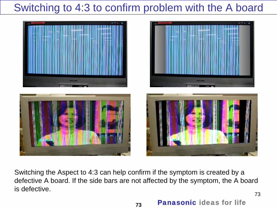
Switching to 4:3 to confirm problem with the A board
Switching the Aspect to 4:3 can help confirm if the symptom is created by a defective A board. If the side bars are not affected by the symptom, the A board is defective.
Panasonic ideas for life

74
D Board (Format Converter/Plasma AI Processor)
74
To D5
To P25
To C21
C2 board
To C12
C1 board
To C11
C1 board
Panasonic ideas for life

75
Circuit Explanation
75
The D board consists of a Video/Panel Control circuit, a Discharge Control circuit, and a Microprocessor Control circuit.
The LVDS (Low Voltage Differential Signaling) signal from the A board is processed by the Video/Panel Control circuit (IC9300 and IC9400).
The Discharge Control circuit outputs the Control Data, Sustain Data, and Scan Control Data. The Control Data is used by the Data Drive Circuit boards (C boards). The Sustain Control Pulses are used by the Sustain board and the Scan Control Pulses are used by the Scan board.
The Main CPU IC9003 has multiple functions. It provides the command to turn on/off the Power Supply and the Panel Drive circuit within the D board. It also monitors a number of voltages and circuits providing protection by shutting down the TV when an abnormality is detected. This condition is communicated to the Main CPU in the A board. When this happens, the power LED blinks a specified number of times indicating the circuit that has failed.
Supply voltages P15V, P5V, and STB5V from the power supply are used to drive the circuits on the D board. Other voltages (1.2V, 2.5V, and 3.3V) derived from the P15V are used by the Video/Panel Control ICs (IC9300 and IC9400) and the Discharge Control IC (IC9500).The P15V is monitored by the Main CPU (IC9003) for missing voltage condition.
The P5V is used by the level shifter ICs, IC9802, IC9803, and IC9019. Their functions is to change the Scan Control Pulses level from 3.3V to 5V before they are output to the SC board via connector D20. The P5V is monitored by the Main CPU (IC9003) for voltage drop condition.
The STB5V is applied to a 3.3V regulator (IC9011). The 3.3V output by this IC is used as the supply source (VCC) by the Main CPU IC9003.
Panasonic ideas for life

76
Circuit Explanation (Continue)
76
The LVDS signal form the A board is converted to “video data” by IC9300 and IC9400.
The digital video data is converted to progressive scan and mixed with the OSD data. Other adjustments such as white balance, contrast and color are also corrected by IC9300 and IC9400.
The Plasma AI (Adaptive brightness Intensifier) circuit analyzes the video program level for the distribution of dark and bright components. This circuit is also used to speed up the scanning process and control the number of sustain periods. This increases the brightness and improves the contrast ratio.
The D board provides the scan, sustain and data drive signals.The scan pulses are output to the SC board. The sustain pulses are output to the SS board. The data drive signals are output to the C1 and C2 boards. The C1 board drives the right portion of the panel and the C2 board drives the left portion
Panasonic ideas for life

77
77
Pictures Of symptoms caused by the D board
Panasonic ideas for life

78
78
Adjustments
Panasonic ideas for life
79
Service Mode
79
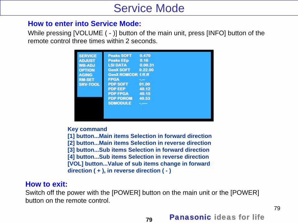
While pressing [VOLUME ( - )] button of the main unit, press [INFO] button of the remote control three times within 2 seconds.
How to enter into Service Mode:
How to exit:Switch off the power with the [POWER] button on the main unit or the [POWER] button on the remote control.
Key command[1] button...Main items Selection in forward direction[2] button...Main items Selection in reverse direction[3] button...Sub items Selection in forward direction[4] button...Sub items Selection in reverse direction[VOL] button...Value of sub items change in forward direction ( + ), in reverse direction ( - )
Panasonic ideas for life

80
80
To access the internal patterns, select [AGING] from the main adjustment menu and press the [3] or [4] button of the remote control to select the desired pattern.
Internal Test Patterns
Panasonic ideas for life
81
Self Check
81
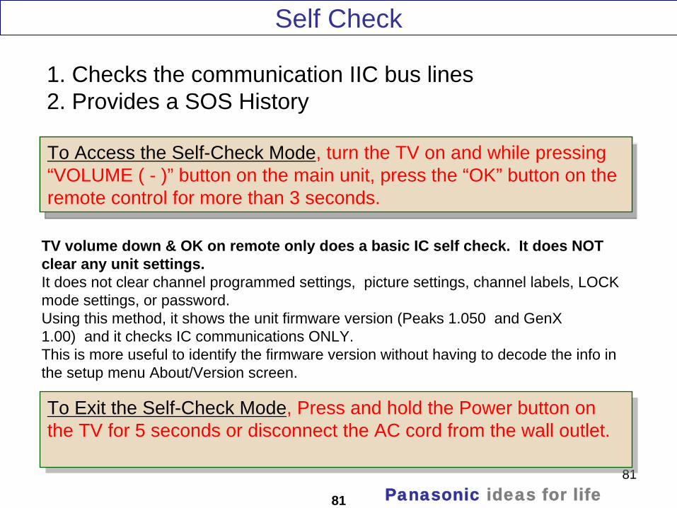
1. Checks the communication IIC bus lines2. Provides a SOS History
To Access the Self-Check Mode, turn the TV on and while pressing “VOLUME ( - )” button on the main unit, press the “OK” button on the remote control for more than 3 seconds.
To Access the Self-Check Mode, turn the TV on and while pressing “VOLUME ( - )” button on the main unit, press the “OK” button on the remote control for more than 3 seconds.
To Exit the Self-Check Mode, Press and hold the Power button on the TV for 5 seconds or disconnect the AC cord from the wall outlet.
To Exit the Self-Check Mode, Press and hold the Power button on the TV for 5 seconds or disconnect the AC cord from the wall outlet.
TV volume down & OK on remote only does a basic IC self check. It does NOT clear any unit settings.It does not clear channel programmed settings, picture settings, channel labels, LOCK mode settings, or password.Using this method, it shows the unit firmware version (Peaks 1.050 and GenX 1.00) and it checks IC communications ONLY.This is more useful to identify the firmware version without having to decode the info in the setup menu About/Version screen.
Panasonic ideas for life

82
Check Point
82 Panasonic ideas for life

83
Self Check Menu
83 Panasonic ideas for life

84
How To Reset
84
Reset forces the TV to factory shipment setting.To reset the TV:Press and hold the “VOLUME ( - )”button on the TV and press the “MENU” button on the remote control for more than 3 seconds.
Note: All customer programmed parameters will be erased.
To Exit:Disconnect the AC cord from wall outlet.
Panasonic ideas for life
85
85
Data Transfer (TV to SD Card – SD Card To TV) How to Copy Self Check Data To SD Card Software Upgrade
Picture Refresh Extension Cable Kit
Panasonic ideas for life

86
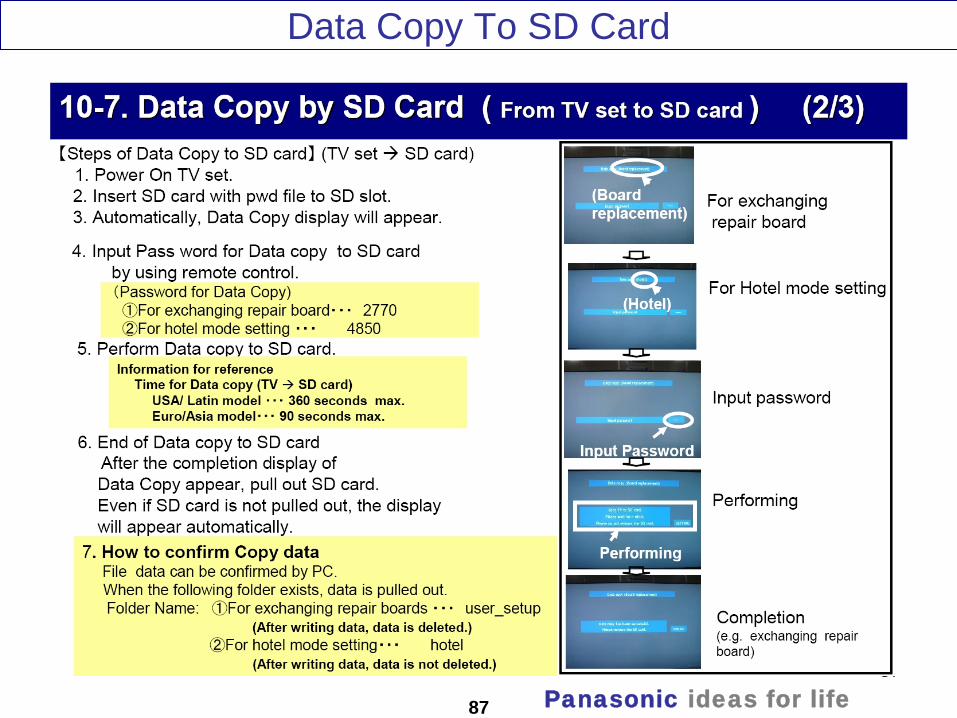
Data Copy To SD Card
86 Panasonic ideas for life
87
87 Panasonic ideas for life
Data Copy To SD Card
88
88 Panasonic ideas for life
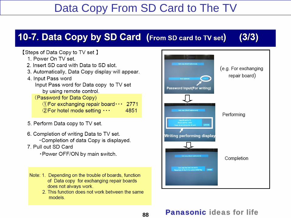
Data Copy From SD Card to The TV

89
89 Panasonic ideas for life
How to Copy Self Check Data To SD Card

90
90 Panasonic ideas for life
How to Copy Self Check Data To SD Card

91
91 Panasonic ideas for life
Software Upgrade

92
92 Panasonic ideas for life
Software Upgrade

93
93 Panasonic ideas for life
Software Upgrade

94
94 Panasonic ideas for life
Software Upgrade

95
95 Panasonic ideas for life
Picture Refresh

96
96 Panasonic ideas for life
Picture Refresh
97
97 Panasonic ideas for life
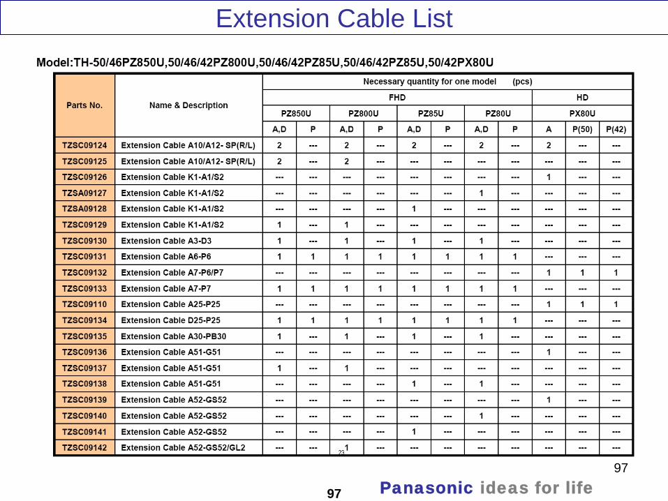
Extension Cable List

98
98 Panasonic ideas for life
Extension Cable List

99
99 Panasonic ideas for life
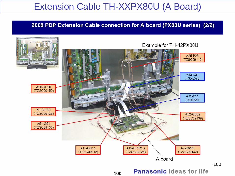
Extension Cable TH-XXPX80U (A Board)
100
100 Panasonic ideas for life
Extension Cable TH-XXPX80U (A Board)

101
101 Panasonic ideas for life
Extension Cable TH-XXPX80U (P Board)

102
102 Panasonic ideas for life
Extension Cable TH-XXPX80U (P Board)

103
Closing session
103 Panasonic ideas for life
Thank you!