1.2 equilibrium of a deformable body from: mechanics of
TRANSCRIPT

1.2 Equilibrium of a Deformable Body
From: Mechanics of MaterialsBy: R.C. HibbelerSolutions by: A.J.P. Schalkwijk MEng

Sum the moments around point A:
Example 1-1, page 11: Determine the resultant loadings acting on the cross section at C of the machine shaft show. The shaft is supported by bearings at A and B, which exert only vertical forces on the shaft.
Determine the reaction forces from the free-body diagram:

Sum the vertical forces:
Sum the vertical forces:
Section the axle at C and create the two free-body diagrams:
Sum the horizontal forces:
Sum the moments around point C:

Since load W is lifted with constant velocity the problem can be regarded static, meaning equilibrium of forces in all directions. First create the free-body-diagrams:
Example 1-2, page 12: The hoist consists of the beam AB and attached pulleys, the cable, and the motor. Determine the resultant internal loadings acting on the cross section at C if the motor is lifting the 500 lb load W with constant velocity. Neglect the weight of the pulleys and beams.

Section the beam at C and create the free-body-diagrams:

note 1: a cable can only transmit tension forces in a straight line. For a cable to transmit a force 'around a corner' external members are required. In this case rollers.
note 2: do not 'double' the loading force on the cable (2x 500 lb). The actual load on the cable is 500 lb. The reaction force is 500 lb. One should not add the load and reaction force.
Consider the example below. Mass M is hanging by a cable and hook H from block A. Block A is supported by columns B and C, who both rest on the floor. The full system is static, meaning the forces on each component are in equilibrium. The free-body-diagram of each component is shown.
The cable and hook are under tension. Block A is both under tension and compression (bending). Column B and C are under compression.

If we now study the free-body-diagram of the cable one could (mistakenly) conclude that the cable is loaded with 100 lb from each end, thus a total load of 200 lb. This is not the case. The action force (A) is 100 lb. The reaction force (R) is equal and opposite the action force, and thus is 100 lb. This is Newtons 3rd law of motion!
Another way of looking at this is; if the action force (A) is lowered, the reaction force (R) is lowered equally, keeping the free-body balanced. The reaction force is not an independent force.
So, to calculate the average stress in the cable's cross section, use 100 lb (action force)! Not 200 lb (action + reaction force)!:

Example 1-3, page 14: Determine the resultant internal loadings acting on the cross section at G of the wooden beam shown. Assume the joints at A, B, C, D and E are pin connected.
Calculate the resultant distributed load and its position:

Create the free-body-diagram and calculate the reaction forces. Since all joints are pin connected, moments are not generated.
*centroid calculation for triangle:
AB, BC and BD are 2-force members, meaning there are just 2 forces acting on each member and since there is equilibrium the forces are equal, opposite and collinear. This means FCy=0.AE is a 3-force member since forces are acting at A, E, D and the 900lb load.

Now calculate the forces in members AB and BD:
Section the beam at G and create the free-body-diagrams:

* The negative sign means that the actual force and moment is in the opposite direction as sketched in the free-body-diagram.
Now calculate M, N and V using the left section:

Example 1-4, page 15: Determine the resultant internal loadings acting on the cross section at B of the pipe shown. The pipe has a mass of 2kg/m and is subjected to both a vertical force of 50N and a couple moment of 70Nm at its end A. It is fixed-connected to the wall at C.
Create the free-body diagram of section ADB.

Main forces at section B:

Problem 1-1, page 16: Determine the resultant internal normal force acting on the cross section through point A in each column. In (a) segment BC weighs 180lb/ft and segment CD weighs 250lb/ft. In (b), the column has a mass of 200kg/m.
Create the free-body-diagrams of the segments up to section A and determine the reaction forces:

Problem 1-2, page 16: Determine the resultant internal torque acting on the cross sections through points C and D on the shaft. The support bearings at A and B allow free turning of the shaft.
Create the free-body diagram and determine the reaction forces: The 3 moments cancel each other out so there are no reaction forces.
Section the shaft at C and D and calculate the reaction forces:
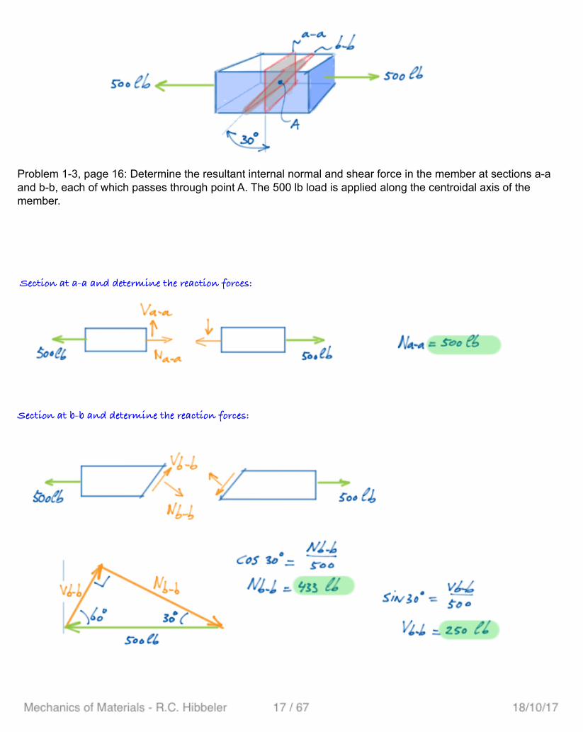
Section at b-b and determine the reaction forces:
Problem 1-3, page 16: Determine the resultant internal normal and shear force in the member at sections a-a and b-b, each of which passes through point A. The 500 lb load is applied along the centroidal axis of the member.
Section at a-a and determine the reaction forces:

Create the free-body diagram and determine the reaction forces:
Problem 1-5, page 17: Determine the resultant interal loadings on the cross section through point D of member AB.

Section at D and create the free-body diagram:

Problem 1-6, page 17: Determine the resultant internal loadings on the cross sections located through points D and E of the frame.
Create the free-body-diagram and calculate the reaction forces:

Section at D and create the free-body-diagram:
Since BC is a 2-force member it is known that Ve and Me are zero.
Double check the left side section:

Problem 1-7, page 17: Determine the resultant internal loadings on the cross section located through points D and E of the frame.
Member AB is a two-force member since it is pin connected and has no external loading acting on it. Create the free-body diagram and determine the reaction force:

Section at E and create the free-body diagram:
Section at D and create the free-body diagram:

Section at C and determine the internal loadings:
Problem 1-9, page 17: Determine the resultant internal loadings on the sections through points C and D of the pliers. There is a pin at A, and the jaws at B are smooth.
Create the free-body-diagram of the separate parts and determine the reaction forces:

Section at D and determine the internal loadings:

Since the hinge is 'locked' the tray is not able to rotate CW. The hinge can be considered as fixed. Create the free-body diagram and determine the reaction forces:
Since 2 arms support the tray all resultant internal loadings shall be devided by 2 *:
* note: the book does not divide the answers by 2
Problem 1-11, page 18: The serving tray T used on an airplane is supported on each side by an arm. The tray is pin connected to the arm at A and at B there is a smooth pin. (The pin can move within the slot in the arms to permit folding the tray against the front passenger seat when not in use). Determine the resultant internal loadings in the arm on the cross section through point C when the tray arm supports the loads shown.
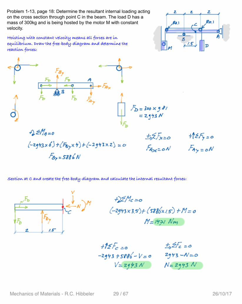
Problem 1-13, page 18: Determine the resultant internal loading acting on the cross section through point C in the beam. The load D has a mass of 300kg and is being hosted by the motor M with constant velocity.
Hoisting with constant velocity means all forces are in equilibrium. Draw the free-body-diagram and determine the reaction forces:
Section at C and create the free-body-diagram and calculate the internal resultant forces:

Hoisting at constant speed means all forces are equalized. Section at B and create the free-body-diagram and determine the resultant internal loadings.
Problem 1-14, page 19: The 800 lb load is being hoisted at a constant speed using motor M, which has a weight of 90 lb. Determine the resultant internal loadings acting on the cross section through point B in the beam. The beam has a weight of 40 lb/ft and is fixed to the wall at A.

Section at B and determine the internal loadings:
Problem 1-15, page 19: The pipe has a mass of 12 kg/m. If it is fixed to the wall at A, determine the resultant internal loadings acting on the cross section located at B. Neglect the weight of the wrench CD.
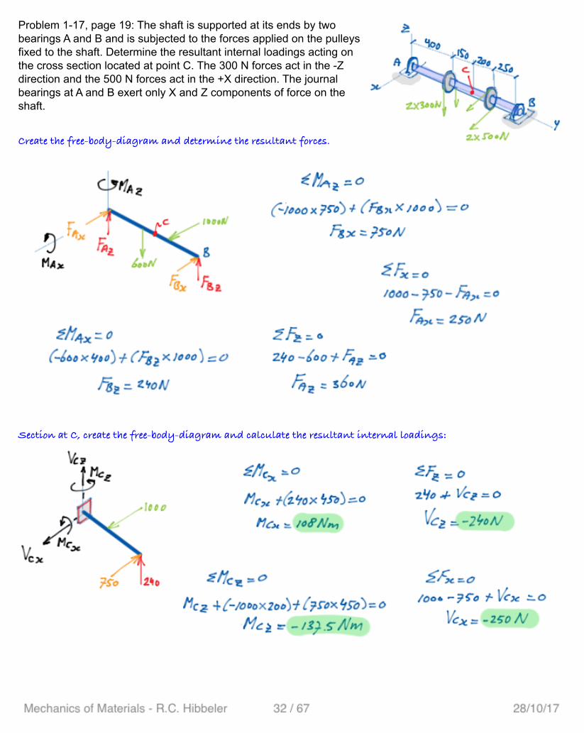
Problem 1-17, page 19: The shaft is supported at its ends by two bearings A and B and is subjected to the forces applied on the pulleys fixed to the shaft. Determine the resultant internal loadings acting on the cross section located at point C. The 300 N forces act in the -Z direction and the 500 N forces act in the +X direction. The journal bearings at A and B exert only X and Z components of force on the shaft.
Create the free-body-diagram and determine the resultant forces.
Section at C, create the free-body-diagram and calculate the resultant internal loadings:
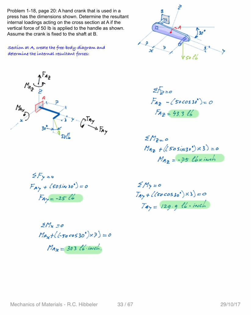
Problem 1-18, page 20: A hand crank that is used in a press has the dimensions shown. Determine the resultant internal loadings acting on the cross section at A if the vertical force of 50 lb is applied to the handle as shown. Assume the crank is fixed to the shaft at B.
Section at A, create the free-body-diagram and determine the internal resultant forces:

Problem 1-19, page 20: The curved rod AD of radius R has a weight per length of W. If it lies in the horizontal plane, determine the resultant internal loadings acting on the cross section through point B. Hint: The distance from the centroid C of segment AB to point O is CO=0.9745r.
Create the free-body-diagram and determine the resultant internal loadings.