12 srs-drivenevolution ofdissipative solitons in fiber...
TRANSCRIPT

12SRS-Driven Evolution of Dissipative Solitons in Fiber LasersSergey A. Babin, Evgeniy v: Podivilov, Denis S. Kharenko, Anastasia E. Bednyakova, Mikhail P.
Fedoruk, Olga v: Shtyrina, Vladimir L. Kalashnikov, and Alexander A. Apolonski
12.1
Introduction
It is known that in optical media with anomalous dispersion, in particular in afiber laser cavity [1- 3], it is possible to generate spectrally limited stable pulsesthat are called optical solitons. It was also found [4 - 6] that the regime of normaldispersion is more suitable for generating high-energy femtosecond pulses. In thisregime, the femtosecond laser oscillator generates chirped pulses, that is, pulseswith frequency modulation across its spectrum. The energy of these pulses maybe ten or even hundred times more than that obtained for conventional solitonsgenerated in the laser cavity with anomalous dispersion.
A cavity with net normal dispersion can be designed in different ways, and theregimes of generated chirped pulses are classified accordingly. Haus in his paper[7] proposed to use a scheme with alternating cavity parts of negative and positive dispersion thus providing dispersion management (DM). If total dispersionof such a DM cavity is close to zero, the oscillator generates so-called stretchedpulses characterized by strong variations of the pulse duration at its round-trip.If the net cavity dispersion is positive and large enough, the pulse varies slowlyin the normal-dispersion (amplifying) part of the cavity taking the shape close toparabolic. Such pulses are called self-similar [8] or similaritons [9]. Strong spectralfiltering in the cavity is necessary in this case [10] to obtain stable pulses. As shownin [11], the similariton and soliton regimes can be realized sequentially inside onecavity in the parts with different dispersion signs.
The concept of dissipative solitons provides a unique frame of understandingfor the existence and properties (including nearly constant parameters) of chirpedpulses that can form and propagate stably in all-normal dispersion laser cavities[12-14]. High energy of the dissipative soliton is reached by means of high pulsechirping and the corresponding increase in its duration at fixed peak power.
Introduced in the 1990s [15, 16] as an extension of the term soliton, the termdissipative soliton (DS) describes localized structures of an electromagnetic fieldin nonconservative systems, where energy exchange with environment becomes
Nonlinear Optical Cavity Dynamics: From Microresonators to Fiber Lasers, First Edition.Edited by Philippe Grelu.© 2016 Wiley-VCH Verlag GmbH & Co. KGaA. Published 2016 by Wiley-VCH Verlag GmbH & Co. KGaA.

2781 12 SRS-Driven Evolution of Dissipative Solitons in Fiber Lasers
important in addition to a balance between nonlinearity and dispersion (or diffraction). Therefore, a balance between gain and loss is also needed to form a stablestructure (see [17, 18] for a review of the DS basic principles and their emergencein optics, hydrodynamics, biology, etc.). Since the gain-to-Ioss balance is a typicalrequirement for laser generation, the concept of DSs has been successfully appliedfor description of pulse dynamics in a laser cavity (see [19, 20] for a review), especially for a broad class of passively mode-locked lasers [21]. The DS concept isalso useful for practical purposes implying for the new cavity designs, in particular,those providing generation of high-energy femtosecond pulses. Being intrinsicallyone-dimensional, stable, and hands-free, all-fiber design of femtosecond oscillators is one of the most attractive for these purposes.
Implementation of the DS concept in fiber lasers led to the generation of rv 10 n]pulses in a scheme with dispersion compensation [22] and 20 n] pulses in an allnormal-dispersion (ANDi) fiber laser consisting of normal-dispersion elementsonly [23]. The pulses are externally compressed to < 200 fs. It appeared that energyscaling is possible by the fiber cross-section enlargement. As a result, the pulseenergy in fiber oscillators has been increased to rv 100 n] at rv 100 fs duration [24].
In theory, stable chirped pulses in normal-dispersion cavity are usuallydescribed in the frame of cubic-quintic Ginzburg-Landau equation (CQGLE)applicable for small variations of the pulse parameters along the cavity; see, forexample, [17,19]. There exists an analytical solution of the equation [25] relevantto optical fibers in the case of relatively small chirp parameterf defined as
f = T d , (12.1)4
where T is a pulse duration and d is its spectral width. Though the solutionobtained in [25] is exact, it is applicable to the pulses close to spectrally limitedones, f ~ 1. In contrast, in the discussed experiments dealing with energyscaling in fiber lasers, net normal dispersion value is high and pulses with chirpparameterf ~ 10 - 30 are generated. So, new approaches are needed for solvinga problem of limitations arising at the DS energy scaling by means of cavitylengthening.
In this chapter, we give an overview of our results on the theoretical description of highly chirped DS (HCDS) based on the approximate analytical solution ofGinzburg- Landau equation in high-chirp limit and its stability analysis [26, 27].Following the developed analytical model describing stable HCDS solutions, westudy experimentally the regime of highly chirped pulses in an Yb-doped fiberlaser with passive mode-locking via nonlinear polarization evolution (NPE) andtest the model predictions. The generated pulses are shown to have equal phaseshifts induced by nonlinearity and dispersion, thus acquiring a linear chirp inaccordance with the HCDS concept. The pulse chirp parameter grows almost linearly with the cavity length leading to nearly linear increase of the pulse energy.The linear scaling, in turn, is valid only up to some extent, beyond which the stability of the regime degrades significantly. The reason of the stability break is shown(both theoretically and experimentally) to be an excessive rotation of the polarization ellipse in the cavity. Therefore, polarization-maintaining fibers for increasing

12.2 Generation of Highly Chirped Dissipative Solitons in Fiber Laser Cavity 1279
the scaling range of the HCDS regime can be a good choice. As a result of thisstudy, an all-fiber configuration free of NPE overdriving based on long PM andshort SM parts was proposed [28]. In this configuration, it appears possible toincrease the cavity length up to 120 m, thus generating stable DSs with energies> 20 nJ and chirp parameters! > 200 being compressible down to ",,200 fs [29].At this stage, a new limiting factor comes into play, namely stimulated Ramanscattering (SRS).
The detailed analysis of the SRS-driven evolution of DS in such long cavities hasbeen performed in the frame of nonlinear Schrodinger equation (NSE) in whichSRS term is added, and the model has been compared with the experiments[30]. It appears possible to realize stable DS in the presence of strong SRS effect.Moreover, with a new laser scheme based on the critical elements describedearlier and an additional Raman feedback loop, stable linearly chirped DSs atStokes-shifted wavelength, so-called Raman dissipative solitons (RDS) wererecently demonstrated [31]. Together with the main DS, the Raman DS (RDS) ofdifferent orders form a multicolor complex of coherent pulses with higher totalenergy that can be, under certain conditions, compressed to sub-100 fs duration.Potential applications of the RDSs and the DS - RDS complexes are discussed atthe end of this chapter.
12.2
Generation of Highly Chirped Dissipative Solitons in Fiber Laser Cavity
12.2.1
Modeling
Newell showed in 1974 [32] that, in approximation of slowly varying amplitude,the equation for an envelope of the electromagnetic wave has a universal form andmay be reduced to the cubic Ginzburg-Landau equation (CGLE). This equationand its generalizations, for example, including different higher-order nonlinearand dissipative effects, are used as a basis for description ofwave dynamics in various physical phenomena, from hydrodynamics and plasma to femtosecond lightpulses [7]. It is also important that this class of equations has soliton solutions inthe broad range of physical parameters. It is clear that the solitons are observablein the experiment if they are stable. Therefore, many papers are devoted to thenumerical studies of CGLE solutions stability, see, for example, [17] and citationstherein.
As mentioned in Section 12.1, a physically important class of the solitonsolutions of Ginzburg - Landau equation is the highly chirped dissipative solitons(HCDS). Strongly inhomogeneous phase distribution characterizes physicalltheir capacity to redistribute energy without loss of stability. As will be demonstrated later, this property can provide energy scalability of HCDS. In the case ofslow saturable absorber, whose relaxation time is comparable to or greater thanthe pulse duration, the CGLE can be solved exactly [33]. The solutions obtained

280 I 12 SRS-Driven Evolution of Dissipative Solitons in Fiber Lasers
in that paper have a spectral profile with sharp edges, typical for DSs. In the caseof fast nonlinearity, where the response time of the medium is much shorterthan the pulse duration, attempts of the DS description in the frame of CGLEapproach revealed that the solutions are unstable against amplitude blow up[34]. A reason of such behavior is physically obvious for positive self-amplitudemodulation (SAM): an intensity growth enhances a nonlinear gain that inducesa further increase of intensity. As a result of such positive feedback, the peakpower increases unlimitedly. Physical senselessness of such a solution is obvious:a nonlinear gain cannot grow unlimitedly. Hence, one may conclude that theCGLE should be modified by an inclusion of SAM saturation.
From this point of view, a simplest master equation for the envelope £(z, t) =1/V2(Az,tei(cvt-kZ) + A;,te-i(cvt-kZ)) may be rewritten as [17]
which is usually named as the CQGLE. Here, z coordinate is normalized by cavitylength L. The first two terms describe group-delay dispersion (GDD) and selfphase modulation (SPM) distributed along the cavity; therefore, they grow withL. In long cavities (in the HCDS regime), these terms are much higher than theremaining four-point action terms describing a difference between loss and gain(()), spectral filtering (a), SAM (K), and SAM saturation (() at a cavity round-trip.All the parameters are positive for the chosen designation. Spectral filtering is naturally present due to a finite width of the gain spectrum and may be enhanced byinsertion of the additional filters into the cavity. SAM is implemented in experiments in various ways, namely by I(err lensing [6], nonlinear optical loop mirror(NOLM) [4, 35], saturable absorber [36], or via nonlinear polarization evolution(NPE) [5, 7], thus providing mode-locking.
Equation (12.2) is applicable ifvariations of the pulse parameters are small at thecavity round-trip. As was shown in [37], Eq. (12.2) is applicable for the descriptionof high-energy HCDSs formation in a Ti : Sa laser. The CQGLE also proved itseffectiveness in the modeling of fiber lasers [14,38-40]. A typical block schemeof ring fiber laser, which can be considered in the framework of CQGLE, is shownin Figure 12.1a.
The complex pulse envelope A(t) averaged along a cavity can be found as asolution of Eq. (12.2) under the stationarity condition aA = iqA, where q is theazwave vector shift. An exact weakly chirped dissipative soliton solution of theCQGLE, which exists in a region of normal GDDs has been first demonstratedin [41]. Such a soliton can be expressed in the form A = a(t)l+if' if' correspondsto dimensionless chirp parameter introduced earlier in the limit I' rv I » 1)and its existence is provided by some fixed algebraic relations between theparameters of Eq. (12.2) [25]. Stability analysis and study of existence domainfor this chirped soliton solution were performed in [25,42,43]. The high chirplimitI --+ 00 requires that changes of a field phase prevail over the field amplitudethat corresponds to the following conditions imposed on the system parameters:spectral filtering is much weaker than the round-trip GDD (a « fJ2L), and SAM

12.2 Generation of Highly Chirped Dissipative Solitons in Fiber Laser Cavity 1281
(a)
Calculation
model L
Out
(b)
Experimentalsetup -----+
+-- 980 nm pump
Yb3+
WDM
QWP 40/0 PBS QWP
•-~- -;(--0- -- ~~--Collimator Y 0 Y HWP Collimator
Mon. ut
Figure 12.1 (a) Block scheme of a fiber laser with ring cavity configuration, (b) typicalscheme of the real experimental setup.
is much weaker than the net SPM (K « yL). These conditions have to be fulfilledsimultaneously to enhance the phase effects causing pulse chirping. In this limit,the chirp parameter is expressed simply via coefficients describing equationparameters (see [25], for instance):
f ~ 3L/(2a/P2 + K/y). (12.3)
The exact solution [25, 41] becomes singular for f > 0; that is why powerful technique to analysis of HCDSs withf » 1 based on the WI(B ideology wasinvented in [26,44]. Such an approach has been expanded in various generalizations of the nonlinear Ginzburg- Landau equation [45, 46]. In the next section, wepresent a sketch of the theory for energy scalable HCDSs.
12.2.1.1 Analytical Solution of CQGLE in the High Chirp Limit
In a nutshell, an HCDS solution ofEq. (12.2) in the limits off» 1; a ~ P2L/2f «P2L and K ~ yL/f « yL can be expressed in the following way [26,27]. A scalingin the time domain t = rf allows expressing a wave envelope in the form
A(z, t) = a(r, z)ei!'P(r,z)-iqz, (12.4)
where ¢(t) = fl.J!(t/f, z) is a phase. The physical sense of such a scaling is thata chirped pulse is stretched by f times in the time domain compared with atransform-limited pulse. In this case, the time (r) derivatives of a and l.J! becomefinite in the limit of f ~ 00, and we can define explicitly the vanishing termsof Eq. (12.2). Substituting Eq. (12.4) in Eq. (12.2) and separating its real andimaginary parts results in two equations for a'P and?!!:. (see [27]).az az
The first principal step consists of the assumption that for an HCDS if » 1)
one may neglect the terms of the order of 0(1/f2 ). In a steady-state regime with
( ~: = 0), it allows obtaining the strict relationship between an instantaneous
power pet) = perf) = a2(r) and an instantaneous frequency O(t) = a¢ = aqJ(r):at ar
(12.5)

(12.6)
2821 12 SRS-Driven Evolution of Dissipative Solitons in Fiber Lasers
where Pm = q/y is a peak power at a pulse center where Q == o. Thus, the shapeof a pulse is defined explicitly by its instantaneous frequency. The requirementP(rf) > 0 in Eq. (12.5) leads to the conclusion that the spectrum has to be truncated at some maximum frequency deviation ~:
~2 _ 2yPm- /3
2•
It is important that the theory allows explicit expressing an instantaneousfrequency in the form of first-order ordinary differential equation (for detailssee [27]).
The second principal step concerns excluding of the physically meaninglesssolutions corresponding to dO. = 00, that can be realized by the regulariza
dttion technique [26, 47] removing the divergences. It leads to the two-valuedexpressions for the HCDS peak power Pm:
+ 3 ( V· 2 (5')Pm = 8( 2 - C ± (2 - C) - 16~ , (12.7)
(12.8)
(12.10)
where parameter C == 2ay / K: /32 is introduced. Thus, there exist only two nonsingular HCDSs of CQGLE; its instantaneous frequency can be expressed in thefollowing form:
dQ =~ [Q2(t) +~ (1 + C) _ lOy P ] (p _/32 Q2(t)) .dt 3yL /32 ( 3/32 m m 2y
The solution to this equation may be written in an implicit form [26] for bothpositive (Pm = P~) and negative (Pm = P;) branches of Eq. (12.7):
arctanh (Q(t)) + 1:. arctan (Q(t)) = i.. (12.9)~ R R~ T
Here, Ll = V'!:J..Pm defines the width of a truncated HCDS spectrum,/32
T = 6~2L 2 is a characteristic time that defines a pulse duration, and R/32SKD. (l+R )
is a parameter defining the pulse shape. The last can be expressed as
R=V1+C_~(Pm 3
The third principal step of the theory is its representation in the Fourier domain.With a scaled time variable t = fr, one may come to
A(ro) =1 / dr a(r)ei!ClJ'Cr)-wr). (12.11)
In the high-chirp limit off ---+ 00, the integral can be calculated by the method ofstationary phase that results in the following asymptotical expression [48]:
A (co) = f a(r*)eif(qJ(T*)-WT*) •
-if~ Ir=r' (1 + 0(1/1)),(12.12)

12.2 Generation of Highly Chirped Dissipative Solitons in Fiber Laser Cavity 1283
where r*(OJ) is the point of stationary phase defined by condition ~~ Ir=r' = OJ for
any frequency w. Taking into account of a2(r) = pet) = Pm - f!1.Q2(t) and d2
; =2y dr
!~~ that is defined by Eq. (12.8) result in [27]
61CyL 1lew) =IA(w)1 2
~ -- 2 2 2 (1 + 0(1/!)) atlwl < L1.(K w +RL1
(12.13)
At Iwi> L1, there is no point of stationary phase and, thus, the integral(Eq. (12.11)) tends to zero (l(w) = 0) asymptotically for! --+ 00.
As a result, the theory allows expressing the HCDS energy:
- / dw 121CyL arcctg(R)£= -l(w)=-- .
21C (KL1 R(12.14)
The most impressive phenomenon, which is revealed by the theory presented,is an energy scalability of HCDSs. As one can see, the HCDS shape P(t)/P± =
B(t/T), spectral profile l(w)/l(O) = A(w/L1), and pulse energy £ depend on theonly parameter R. If all six parameters of the initial equation are changed at anR value kept fixed, then the HCDS shape in time domain and its spectrum willchange in a self-similar way, that is, its amplitude, duration, and chirp as well as thespectral amplitude and width will scale with the conservation of soliton shape. Inthe limiting case of (Pm « 1 (R --+ (0), the solution pet) tends to sech2(t/T), thatis, to the transform-limited CGLE solution. However, an opposite limit (R --+ 0)corresponds to an HCDSs with rectangular profile.
Pulse energy, see Eq. (12.14), in these limiting cases tends to lim £ = 0 andR-+oo
lim £ = 00. The last limit for rectangular pulse reveals the phenomenon of perfectR-+O
energy scalability of HCDSs, which is analogous to the dissipative soliton reso-nance reported in [49 - 51], and can be explicated in the form of so-called "masterdiagram" [44]. An iso-gain curve (J = 0 on the master diagram corresponds to condition of the HCDS marginal stability and the dissipative resonance condition forit is lim £K3/2(1/2/ya1/2 = 00. If the parameters of spectral filtering, SAM, and
C-+2/3
net-gain (J are kept on some constant level, the energy scaling can be provided bysimple scaling of fiber length L.
It is important to note, that HCDS solutions exist in the limited regions of thewhole domain of CQGLE parameters [27]. Since the pulse power must take onlypositive real values, it follows from Eq. (12.7) that the HCDS solutions are absent in
the region C == 2ay / P2/( < 2 - 4~. The definitional domain for analytical solu-
tions is shown in Figure 12.2 on the ( C, ~) plane. Numbers (I) and (II) denote
the regions where HCDSs do not exist [27]. The condition of the pulse spectrumlimitation R2 > 0 defines the HCDS existence regions for the positive (Pm = P~)
(IV) and the negative (Pm = P;;) (III, IV) branches. In this diagram, the dissipative resonance condition (R = 0) corresponds to the dividing border between theregions III and IV.

2841 12 SRS-Driven Evolution of Dissipative Solitons in Fiber Lasers
0.25 ..-------,------.-------,----.--------,~II
0.21- ·.."'····························..·.. ········.:.··· ; ., , -;
0.15~
~b
0.1
0.05
04···....
0 0.4 0.8 1.2 1.6 2
C
Figure 12.2 Solution existence areas in theplane (C, (jt; /K): positive (Pm = P~) branchof the analytic solution exists in the area IV,negative (Pm = P;) branch-in the areas III
and IV. Coordinates of the example numerical solutions are marked by points. Dottedlines illustrate the paths with self-similarpulse shape corresponding to R= const [27].
12.2.1.2 Comparison of Analytics with Numerics
It is important to analyze the stability of both branches of HCDS existing in theregions III and IV. Such an analysis was based on the numerical solution of Eq.(12.2). The technical details of the calculations can be found in [27].
In region IV of Figure 12.2, the points with coordinates (C, (5'/K) equal to(0.9,0.04), (0.5,0.13), (0.75,0.006), (1.5,0.007) are marked by the numbers 1,2,3,and 4, respectively. For each point, we performed several simulations with variousinitial conditions including a Gaussian shape pulse, an analytical solution, andwhite noise [27]. It was found that for any parameter set inside region IV, thereexists a stable analytical solution (positive branch). Numerical simulation withany initial perturbation converges to this solution. On the contrary, in region III,it was not possible to obtain any stable solution, even if the analytical solutionsfor negative branch were taken as the initial approximation. All the initialapproximations either decay after 300- 500 round-trips or broaden unlimitedlyin time domain at the constant amplitude. Note that a similar behavior hasbeen observed in [42] for the negative branch of the solution for weakly chirpedsoliton [41].
The obtained results lead to the conclusion that the negative branch solution isunstable in its all-definitional domain (regions III and IV), whereas the positivebranch solution is stable in its region of existence (IV).
In region II, both solution are absent since R2 < O. We performed simulationsfor several points in regions I and III with different parameters of the initialequation. It was found that in region I there exist stable solutions correspondingto weak chirp f ~ 1, whereas highly chirped solutions f » 1 are absent in thisregion. At the same time, we have not succeeded in realizing any stable eitherweakly or highly chirped solution in region III. Therefore, it is possible to

12.2 Generation of Highly Chirped Dissipative Solitons in Fiber Laser Cavity 1285
1 1
0.8 0.8
2: 0.6 + E 0.6Q
::::: 0.4 0:: 0.4
0.2 0.2
0 02.45 2.45
0.1 0.48 0.1(a) (b)
Figure 12.3 (a) Comparison betweennumerics (color) and positive branch of theanalytical solution (solid black) for the spectral shape. (b) Time-domain shape of the
positive branch (solid) and fitting (dashed)by parabola and sech2
. Additional blackcurve shows analytics in the limit R ~ 0(R= 0.1).
conclude that region IV is the only domain of existence and stability for all thehighly chirped solutions of Eq. (12.2).
We also compared numerical simulation and analytical solution in points 1-4of region IV in Figure 12.2. For all these points, the result of numerical simulation coincides with the analytical solution for positive branch in all its definitionaldomain (Figure 12.3). This means that the shape of the HCDS solution of theEq. (12.2) at high chirp condition actually depends only on the value of parameterR being independent of other parameters of the equation. The values of parameterR for curves intersecting the points 1, 2, 3, and 4 shown in Figure 12.2 are equal toR ~ 1.03,0.65,0.48,2.45, correspondingly. The performed numerical analysis hasshown that along these curves the solutions are self-similar, that is, the shape ofthe pulse and the shape of its spectrum do not change.
In Figure 12.3, the spectral and temporal shapes of HCDS are shown at variousvalues of parameter R, corresponding to dashed lines in Figure 12.2. Analyticalsolutions are obtained from Eqs. (12.5) and (12.9). According to discussion in theanalytical section, at R = 2.45 the pulse shape is approximated well by the expression sech2
, that is, is close to the shape of standard NLSE soliton. With decreasingR the shape is changed and tends to parabolic one in point 3 (near the left borderof region IV). In the limiting case ofR -+ 0 (exactly at the left border of region IV),the pulse takes the shape close to rectangular one: P = P~(l - R2tan2(R tiT)) att < !..!!...
R 2Since exact solutions of CQGLE [25, 41-43] are singular at high chirp, our
demonstration of stable HCDSs of CQGLE has high theoretical and practicalsignificance [27, 44]. Only one of two solutions appears to be stable (+ branch innotation of paper [26]) in the absence of gain saturation. This is similar to the caseof weakly chirped solitons [25, 41-43]. This fact is rather common and followsfrom more general mathematical theory of bifurcations. In addition, directcomparison of the analytical solutions for the pulse spectra with the numericalones demonstrates the 10-2 -10-4 accuracy for chirp parameters f > 10. Theexistence domain for the stable HCDS solutions with possibility of its self-starthas been found in the CQGLE parameters set. Meanwhile it has been shown thatthe stable solutions correspond to the HCDS family with only one parameter

2861 12 SRS-Driven Evolution of Dissipative Solitons in Fiber Lasers
R described by the expression (12.10). Inside this family the pulse shape ischanged from the conventional soliton shape of sech2 at R --+ 00, to rectangularone at R --+ 0, with a shape close to parabolic one in between: at R rv 0.5. Thisparameter may be calculated for any experimental configuration and one canperform a quantitative comparison with experiment that makes a significant stepin development of analytical theory.
The obtained theoretical results make it possible to classify experimentallyobserved HCDS pulses and to optimize experimental schemes aiming at thegeneration of pulses with various shapes.
12.2.2
Experiment and its Comparison with Simulation
Since the approximate analytical solution is applicable in the high-chirp limit,f » 1, it corresponds to conditions of most experiments with fiber lasers ofANDi type generating highly chirped pulses (HCP) [23, 29, 52, 53]. This modelalso shows that spectral shaping may be achieved even without strong spectralfiltering produced by an additional filter element. Stability analysis of the solution[26] performed in papers [27, 54] has shown that only one of two solutionbranches appears to be stable. At that, stable solutions may be represented asone-parameter family with composite parameter R defining the pulse shape, asshown in Section 12.2.1.
In this section, we explore the developed analytical model [26, 27] for verification of the HCDS regime in the experiment, for optimization of the experimental scheme and for testing of energy scaling possibilities by means of cavitylengthening.
A scheme of the experimental setup that we use to study the regimes with HCPin a Yb-doped fiber laser [28] is presented in Figure 12.1b. The scheme is similarto those in [13,23], but with one significant difference-we do not use any additional spectral filters for achieving the HCP regime. The laser consists of fiberand bulk optics parts. The fiber part includes (clockwise starting from the lefttop side): WDM coupler with 45 cm and 30 cm fiber tails, 15 cm active singlemode fiber (SMF) with high Yb3+ concentration, 80 cm passive XPI060 SMF ofvariable length and isolator with 30 and 85 cm tails. In the bulk optics part, wehave quarter-wave (QWP) and half-wave plates (HWP), polarization beam splitter (PBS), 4% plate to monitor intracavity parameters of the laser and second QWPto produce slightly elliptic polarization at the input of the fiber part, necessary forNPE effect.
As the active fiber is highly doped its absorption amounts to 900 dB m- I at976 nm. A polarization insensitive fiber isolator has 2 dB losses at 1030 nm. Thepumping is produced by a single-mode laser diode (LD) of up to 400 mW opticalpower at 976 nm. A monitoring port formed by 4% plate is used for measurementsof the intracavity power and spectra. An output pulse train is observed on theoutput port of PBS used for output pulse width and power measurements. Thepulse width is measured by scanning interferometric autocorrelator operating in

12.2 Generation of Highly Chirped Dissipative Solitons in Fiber Laser Cavity 1287
the range from 10 fs to 6 ps. The pulse spectrum is measured by Yokogawa opticalspectrum analyzer with wavelength range from 600 to 1700 nm and wavelengthresolution of 0.02 nm. The pulse train is also monitored by a fast oscilloscope incombination with a I-GHz photodiode.
In the experiment, we have realized the HCP regime at four different values ofcavity length: 4.5, 3.6, 3.2, and 2.6 m with the corresponding repetition rate 44,55, 63, and 78 MHz. In all configurations, the studied HCP regime is found to bestable. Its self-starting is achieved by means of HWP tuning, without any external amplitude modulator. The threshold pump power for stable mode-locking isvaried from 250 to 350 mW. At lower powers, the laser generates CW radiation orstochastic pulses. At higher power, the mode-locking is unstable and tends to CWregime. Note that the power range of stable operation is significantly reduced incase of the longest cavity.
Several measurements of spectrum, autocorrelation trace and laser power havebeen taken for each cavity length. Both the intracavity and extracavity spectra havesteep edges with more than 30 dB contrast that is typical for HCDS regime. Fullwidth of the intracavity spectrum at -10 dB level is in the range of 12 -14 nm. Themeasured output pulse width varies from 1.3 ps for the shortest cavity to 3 ps forthe longest cavity. The pulses were compressed externally by diffraction gratingpair to about 250 fs [28].
The energy of output pulses, measured at the output port of PBS is presentedin Figure 12.4a. Dotted line is a linear fit for the first three groups of points.Different points in one group correspond to mode-locking regimes with differentlevel of pump power and slightly different adjustments of the phase plates, correspondingly. The energy value for the fourth group of points deviates significantlyfrom the linear dependence and, therefore, this group was excluded from thefitting. We consider this point and reasons of its deviation in later sections.Note that the intracavity power is rv 2 times higher than the output one andamounts to 1 nJ.
We can also calculate chirp parameter (Eq. (12.1)) using measured values ofthe full spectral width ~ and duration of the chirped pulse T. The dependence of
20lIl,,,,,,,;0.7 1.2 . . .
15....{ ...J....
_......................................
....0.6 10 L,rn
..s C\J 0.8E- 0.5 2 2.5 3 3.5 4 <l
>.
..............J...............f ·········~ 0.60) -0 44 MHz.
Q5 Qc 0.4 >-.. 55 MHz.W C\I 0.4 63 MHz ...
0.3 78 MHz.0.2
0.2 01.5 2 2.5 3 3.5 4 4.5 200 250 300 350 400
(a) Length of cavity (m) (b) Pump power (mW)
Figure 12.4 (a) Energy of the output pulses depends on cavity length; inset -dimensionlesschirp parameter defined by Eq. (12.1); (b) nonlinearity and dispersion phase shift ratio overone round-trip in the cavity [28].

2881 12 SRS-Driven Evolution of Dissipative Solitons in Fiber Lasers
the dimensionless chirp parameter versus cavity length is presented in the insetin Figure 12.4a. Note that the chirp parameter value at the longest length is alsoout of the linear trend, similar to the pulse energy. Let us compare the obtainedexperimental results with theoretical relations [26, 27].
Since our experimental results are in the area of applicability of the analyticalsolution, we should observe the same behavior in the theory and experiment. Oneof the important consequences of the theory is possibility of scaling provided bythe linear dependence of chirp parameter on the cavity length (see Eq. (12.3)).As can be seen from the experiment (inset in Figure 12.4a), it is true for threeexperimental points with cavity lengths shorter than 4 m, but at the fourth pointthe chirp parameter deviates significantly from the linear dependence, similar tothe pulse energy (Figure 12.4a). Reasons of this deviation will be also discussedlater.
Another important theoretical issue characterizing HCDS is a balance betweennonlinearity and dispersion phase shifts (Eq. (12.6)), so in theory their ratioshould be equal to unity (as presented in Figure 12.4b by thick line). The figurealso presents experimental points for this ratio calculated from the measured dataand the specified fiber parameters. Average peak power Po defining nonlinear
phase shift is calculated as Po = L~=l PiLil L~=l Li' where Pi and Li is the peakpower and length in the ith section of cavity correspondingly (see Figure 12.lb).We have divided the cavity into three sections having different power levels. Firstone is between the fiber input and active fiber (minimum peak power). Secondone is between active fiber and isolator (maximum peak power). Third one isbetween isolator and PBS.
The derived experimental points are marked by different colors/signscorresponding to different lengths (as in Figure 12.4a). The points locate aroundtheoretical value in the region between 0.8 and 1.2 for all pump power andlength values. We can, therefore, conclude that highly chirped pulses obtainedin the experiment can be attributed to dissipative solitons. It is an importantresult meaning that a femtosecond oscillator can be described analytically bythe developed theory in its applicability domain, f > 10. In order to explainsignificant deviation of the last point in length dependence (corresponding tothe longest cavity length) both for energy and chirp parameters, we have appliednumerical simulation described in the next section.
12.2.3
NPE Overdriving and its Influence on Dissipative Solitons
As follows from the experimental data (Figure 12.4) simultaneous linear growth ofthe chirp parameter and pulse energy with the cavity length breaks at some criticalpoint (corresponding to cavity length of 4-4.5 m) that contradicts the analytical model predicting unlimited linear growth. To identify reasons leading to suchcritical behavior, we should go beyond the scalar model of CQGLE and performnumerical simulation in vectorial NPE model.

(12.16)
12.2 Generation of Highly Chirped Dissipative Solitons in Fiber Laser Cavity /289
To describe directly polarization vector evolution, we should treat vectorialequation for electromagnetic field amplitude E(z, t) (see, e.g., [55]):
aE± = [i fJ2 !:.- _ iyI + ~(IE 12 _ IE 12)] Eaz 2 at2 - 3 + - ±
go 1+--W- 2 E+, (12.15)
1 + - [1 + J...~] -Ws ~i ot2
1= 1£+12 + I£j, W = / I(t)dt = / j(Q);~,
where Ws = Ps TR is the saturation energy, TR = Lno/ c is the cavity round-triptime, ~1 is the half width of the gain spectrum, go is the small-signal gain
coefficient, and E± = (E1 ± iE2 )/ -12 are right-hand and left-hand circularpolarizations of the electric field. In the simulation, we use experimental values ofthe dispersion, nonlinearity, and loss coefficients presented in Section 12.2.2. Ateach cavity length, an optimization of the output power is performed by means ofthe waveplates rotation thus changing polarization state. The calculated outputpulse energy grows linearly with the cavity length. The growth is terminatedat some critical length similar to that in experiments [28]. The higher thepolarization ellipticity the lower the critical length and maximum pulse energy,accordingly. Herewith, the value of polarization rotation angle tends to n /2 at thecritical length thus leading to ambiguity in SAM.
These results agree in general with previous results on normal-dispersion cavityfiber lasers [13, 23, 56] where NPE "overdriving" was mentioned, but here we clarify in detail the physical mechanism of limitations at cavity lengthening, explainedon the base of the vectorial NPE model [55] . Note that the existence of criticallength was mentioned in paper [56] where similar pulse energy level (~1 nn hasbeen obtained in 18-m long (9.9 MHz) cavity of Er-doped fiber laser generatinglinearly chirped pulses compressed down to S 200 fs. In paper [57], a possibilityof energy scaling by cavity lengthening of Yb-doped fiber lasers is analyzed on thebasis of numerical simulation demonstrating gradual degradation of stability atlengthening from rv 10 to rv 100 m.
The presence of critical length and its value in our experiments agree with theperformed numerical simulation based on vectorial model for NPE effect [28]. Therelatively low value of critical length in our case is defined by significant losses inbulk optics part of the cavity and light input-output of the fiber. Atthat, the reason for the HCDS regime break at critical length is found to be defined by theexcessive (> n /2) rotation angle via NPE effect in the fiber leading to instabilities/stochasticity and multiple pulse regimes. For lower losses and lower ellipticityof the pulse polarization at the fiber input, the model predicts larger critical length,but its maximum value will be limited by random birefringence of the fiber andits sensitivity to environment.
Based on the earlier results, we can propose a possible way how to overcomethis limit. To keep the rotation angle lower than n /2, one should increase the totallength of the cavity by means of the polarization maintaining (PM) fiber in which

290 I 12 SRS-Driven Evolution of Dissipative Solitons in Fiber Lasers
rotation is absent, whereas the length of the conventional non-PM SMF fiber partshould be fixed (or even shortened) to keep the NPE-induced rotation angle within1r/2 limit. As a result, nonlinear phase shift (and corresponding dispersion shift)accumulated along the PM-fiber part will lead to the HCDS pulse formation, whilenonlinear polarization rotation in SMF part will provide stable mode-locking. Theexperiments in this configuration confirm the absence of NPE overdriving effect,but revealed new limiting factor of cavity lengthening, namely SRS resulting in DSenergy conversion into noisy Raman pulse (RP) generated at the Stokes-shiftedwavelength. This effect will be considered in detail in the next section.
12.3
Scaling of Dissipative Solitons in All-Fiber Configuration
12.3.1
Different Ways to Increase Pulse Energy, Limiting Factors
Scaling of the pulse energy in the ANDi laser generating highly chirped DSsis possible by increasing its cavity length or mode-field diameter of the fiber.Outstanding results on energy scaling were obtained by implementing intracavitylarge-mode-area (LMA) photonic crystal fibers [24, 36]. Peak power of generatedpulses achieves level of about 1M~ which is close to the self-focusing thresholdin the fiber of rv2 MW [58]. At the same time, LMA fibers (with a core diameter> 20 J.l m) are not strictly single-mode, which adversely affects not only the qualityof the beam, but also the stability of the single-pulse regime [59]. Moreover, suchschemes utilize free-space polarization optics at the expense of environmentalstability.
The most successful attempt of the YDFL cavity lengthening [23] resulted in thegeneration of < 200 fs dechirped pulses with energy increased to rv 20 nJ at 12.5MHz repetition rate (with 6 J.l m core fiber and free-space optics). Using a narrow(5 nm) spectral filter inside a resonator, it was possible to obtain generation at arepetition frequency of 3 MHz [60]. In this case, the pulse energy at the output ofthe oscillator was 15 nl, and the duration after compression was 670 fs. In addition,the work focuses on the prospects of amplification of such pulses, since the radia- tion of a chirped pulse generator can be sent directly to an amplifier, without usinga stretcher, preamplifier, and modulator. Jiang et al. [61] reduced the pulse repetition frequency to 2.3 MHz using an Er-doped fiber as the active medium, whichalso acts as an efficient spectral filter. They succeeded to reach acceptable environmental stability in 90-m long SMF with NPE mode-locking in spite of its extremesensitivity. High long-term stability of repetition frequency and laser operationwas observed for more than two weeks, although the NPE effect in a long SMFis very sensitive to external influences. The maximum pulse energy at the laseroutput was 9.4 nJ.
Interesting results have also been obtained in attempts to increase the resonatorlength without spectral filters. The creation of a high-energy femtosecond pulse

12.3 Scaling of Dissipative Solitons in All-Fiber Configuration 1291
system with a repetition frequency of 4 MHz (resonator length 50 m) is reportedin [62]. Here, the resonator of the master generator is made of SMF-28 telecommunication fiber with a core diameter of 8.5 ~ m. Mode-locking is provided by theNPE effect, and the active medium is Yb-doped GTWave double-clad fiber. Themaster generator has two outputs with a total energy of 1'.1 10 n] per pulse. I(obtsevet al. [63] also increased the Yb laser length to a record value of 3.8 km, therebyreducing the repetition frequency to 77 kHz and increasing the pulse energy to3.9 ~]. However, this regime was no longer the regime of highly chirped pulses: thespectral width was only 0.35 nm and the duration of the generated pulse was 3 ns.The autocorrelation function (ACF) ofsuch pulses has a two-scale structure with anarrow peak and a broad valley, which correspond to stochastic mode-locking forwhich pulse compression is problematic. As the authors showed later by numeri-cal simulation [57], a transition from coherent (chirped) pulses to stochastic onesin the SMF based schemes with NPE mode-locking occurs at the fiber length ofabout 100 m that is agreed with experiments [61]. In most other experiments, thislength is shorter (1'.1 10 m) because of higher losses and higher sensitivity to environment increasing random birefringence of the fiber, see discussion at the end ofthe previous section.
As reported in [64], the problem of stochastic regime in such ultralong SMFcavities can be principally solved by using another mode-locking technique, forexample, point-action saturable absorber based on single-wall carbon nanotubes.The authors use a synchronously scanning streak camera and a monochromatorto directly measure the pulse spectrogram. This measurement showed that thepulses have a relatively clean temporal profile, and its average chirp appears tobe nearly linear in a broad range thus demonstrating a principal possibility ofso-called giant-chirp oscillators. However, the authors note that it is not possible to compensate for the chirp over several nanoseconds pulse duration with anypractical compression scheme. Moreover, the chirp characteristic has a significantspread in each point of about 0.1 part of the whole frequency range; therefore, itseems hardly possible to compress the pulses by more than 10 times.
Other ways to improve stochastic regime in ultralong cavities include morecomplicated cavity design [65] and implementation of active mode-locking technique [66] in Er-doped fiber laser. In [65] pulse energy of nearly 1.7 ~ ] is obtainedat repetition rate is 35.1 kHz in a fiber laser with a linear-ring cavity. In [66], erbiumfiber laser generates chirped pulses with energy 34 n] at 163.8 kHz repetition rate.
Endeavors to improve environmental stability involved also a use of PM fibers incombination with saturable absorber mirror (SAM) [67] demonstrating generationof 1 n] pulses at 17 MHz rate. In similar linear scheme with PM fibers and semiconductor SAM [60], pulse energy exceeded 2 nl, but in both schemes dechirpedpulses are longer (2: 300 fs) than in NPE-based lasers because of long SAM relaxation time. In addition, all the discussed schemes utilize free-space optics thatdegrades both the system stability and limits possibilities of its practical use.
For practical applications of a laser system an all-fiber design is the mostdesirable, that is also true for femtosecond lasers. All-fiber NPE-based Yboscillator delivering 1.8 nl, 179 fs dechirped pulses at 33 MHz repetition rate

2921 12 SRS-Driven Evolution of Dissipative Solitons in Fiber Lasers
was demonstrated by Schultz et at. [68]. The same group later developed anall-fiber Yb laser with higher (3.6 nn pulse energy [69]. Recently, good resultswere demonstrated with the use of NOLM [70] and NALM [71] (nonlinearoptical or amplifying loop mirror, correspondingly) mode-locking techniques inan all-PM fiber cavity providing exceptional environmental stability. In [71], theauthors develop an all-PM all-fiber giant chirp oscillator and present an evidentpossibility of energy upscaling by cavity lengthening. At the maximum cavitylength L = 100 m, laser generates stable chirped pulses with energies of 16 nJ thatcan be compressed to 370 fs duration. At further cavity lengthening, the authorsobserved a strong Stokes signal induced by SRS and significant stability reductionof a laser generation. They interpreted this fact that SRS is the main reason ofthe stability break treating this mechanism as a fundamental limitation of energyscalability [72].
Note that in the hybrid SM - PM fiber oscillator free of NPE-overdriving discussed at the end ofSection 12.2.3, proposed and realized in earlier papers [28,29],the SRS effect is observed at comparable pulse energies achieved in shorter cavity,but it does not break the pulse stability even at higher pulse energies. This effectlimits the DS energy above the SRS threshold converting all the excess energyinto noisy pulse generated at the Stokes-shifted wavelength, but without stabilitybreak. The experimental realization of such an all-fiber oscillator together withresults on its output parameters and further scaling limitations are presented inthe next section.
12.3.2
SRS Threshold for Dissipative Solitons at Cavity Lengthening
The basic design of the DS all-fiber laser is depicted in Figure 12.5. This YDFLscheme is similar to conventional ring schemes of NPE mode-locked DS fiberlasers [13, 19, 20, 23, 24, 73]. A key difference is that the cavity is divided intotwo parts: very long passive PM fiber part (blue on the scheme) and very short
A Isolator B c
Figure 12.5 Experimental setup of an all-fiber highly chirped OS fiber oscillator.

12.3 Scaling of Dissipative Solitons in All-Fiber Configuration 1293
SMF part (red on the scheme) between polarization controller (PC) and PBS.Such configuration was proposed for elimination of NPE overdriving (see Section12.2.3) thanks to the possibility to control a rotation angle of the polarizationellipse by varying the length of SMF part of the cavity. The first realization ofscheme [29] has confirmed the validity of this concept demonstrating stablemode-locking in a 30-m fiber cavity. In addition to mode-locking, the SMFpart is also responsible for the pulse amplification, balancing the losses on thePBS output and spectral filtering naturally defined by the Yb3+ gain bandwidthand the spectral function of WDM I (see [29, 30] for details). Moreover, sincethe SMF part is much shorter than the PM part, the effects of mode-locking,gain, and filtering may be treated as point-action, while DS evolution definedby nonlinearity, dispersion, and the studied SRS effect is distributed along thePM fiber. It is an important assumption that is used for further simulations inSection 12.4.1. Mention that a cloud-inset on the scheme corresponds to the
. modification that allows us to convert a noisy Raman pulses to a new type of thesolitons - RDSs. This opportunity is discussed in detail in Section 12.4.3.
The SMF part of the cavity with optimal length L SMF rv 1.5 m consists of nonPM SMFs: passive fiber (Nufern 1060-XP) and a 15 cm piece of active Yb3+ -dopedfiber (CorActive Yb-17-05) pumped by 976 nm single-mode LD via 976/1030 nmwavelength division multiplexer (WDMI ). Small-signal Yb3+ gain is rv25 dB atspectral maximum (rv 1025 nm). A PC and a PBS set before and after the SMFpart provide NPE-driven self-amplitude modulation. The DS part consists of onlyPM fiber components: long section (L pM =25-115 m) ofpassive PM fiber (NufernPM980-XP), a PM isolator, and a 1% PM splitter, that is used for a monitoring theintracavity parameters of the generated pulses. The core diameter of the PM fiberused is d ~ 5.5 J.1 m. The dispersion coefficient measured by the fiber white lightinterferometer has the value of /32 = 0.023 pS2 m- I . At the outputs, we have someadditional fiber splitters that are not present in Figure 12.5 being used for simultaneous measurements of power, radio frequency (RF) and optical spectra. Alloutputs of the laser were protected by angled physical contact (APC) connectors.
For a pulse compression, we use a standard double-pass compressor consistingof a grating pair (not shown in Figure 12.5 for simplicity). The pulse width ismeasured by scanning interferometric autocorrelator (Avesta AA-20DD) withinput pulse duration ranges from 10 fs to 6 ps and by FROG (produced byMesaphotonics) with the extended range up to 100 ps (hand made by means ofan additional motorized translation stages). The pulse spectrum is characterizedby conventional optical spectrum analyzer (Yokogawa 6370). Pulse train andradio frequency beating spectrum were monitored at the same time by 1-GHzphotodiode on the oscilloscope and on Agilent N9010A spectrum analyzer,correspondingly.
A linearly polarized pulse is equally affected in PM fiber by dispersion andself-phase modulation providing large linear chirp [28]. So, the fiber laser exhibitsgeneration of stable pulses in all the studied range of the cavity lengths with theirduration 30 - 70 ps nearly proportional to cavity length. The key advantage is thatthe lengthening of PM-part does not lead to the stability loss: the total cavity

2941 72 SRS-Driven Evolution of Dissipative Solitons in Fiber Lasers
20
10
co 0:s~ -10cQ)
~ -20
-30
-20-10 0 10 20
Frequency (kHz)
1000 1020 1040 1060 1080 1100
Wavelength (nm)
20
10
co:s.~ -10cQ)
~ -20
-30
1000 1020 1040 1060 1080 1100
Wavelength (nm)
Figure 12.6 The measured optical pulse spectrum (in -inside the cavity at 1% port, out-out of the PM splitter): spectrum for a maximum OS output energy for 30 m and 90 mcavity length is present on (a) and (b) correspondingly.
length can be easily increased from L rv 30 m to L rv 120 m (repetition rate goesdown from rv7 to rv1.7 MHz). However, already at the L = 30 m (that is abouttwo times more than in Chong et at. [23]) another limiting factor comes into play,namely SRS. In addition to the main DS peak (centered at 1015 nm), a Ramanpeak (centered at 1060 nm) appears in the generated spectrum (see Figure 12.6).It becomes stronger for longer cavities, where a noisy RP develops with an energycomparable with that for a DS. This effect limits DS maximum energy withoutdeteriorating its stability: RF spectra measured at rv 750 MHz remain narrow(rv 1 kHz) and are of high ~ontrast (rv 60 dB, see insets in Figure 12.6) in all studiedrange. For a 30 m cavity length, the maximum pulse energy achieved is 23 nJ(> 150 mW output power at 390 mW pumping), 17 nJ of which corresponds tothe DS. To the moment of publication [29], this result was about one order ofmagnitude higher than the pulse energy in previous all-fiber YDFL configurations[68, 69], and comparable with the best results for SMF-based ANDi laser withbulk optics [23]. Notably, we used fibers of smaller diameters together with lowerpump powers.
To our surprise, we have succeeded in the generation of stable DS pulses atlengths up to L = 120 m (corresponding to the repetition rate F rv 1.7 MHz). AtL = 60 m and L = 90 m, the pulse energy reaches the maximum value of 27 nJ (23nJ of which corresponds to the DS). At the same time, the energy of intracavityDS pulse remains constant at different pump powers. In longer cavity (120 m), theoutput DS energy slightly decreases. Nevertheless, at all cavity lengths the optical spectrum has a shape characteristic for a highly chirped DS (with steep edges,see Figure 12.6b). More detailed discussion on intracavity and extracavity pulseenergies can be found in [74].
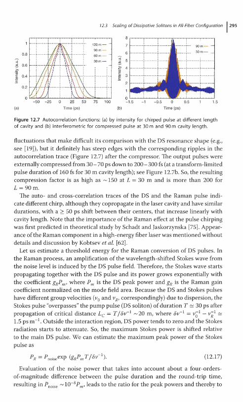
For all cavity lengths, the ACF for both chirped and dechirped DS pulseshas been measured. The intensity autocorrelation trace has triangle shape,see Figure 12.7a, that corresponds to the rectangular pulse shape of the sameduration, in accordance with theoretical predictions [26, 27]. In terms of analytic solution for highly chirped DS [26, 27], this domain is characterized by asingle composite parameter R tending to zero. However, the DS spectrum has
12.3 Scaling of Dissipative Solitons in All-Fiber Configuration 1295
8,.....-..-.--.-..,.....-.,.....,................--...........-.--rr""""-'--'--'''''''''''''''''''''''''''''-''''''''-''''''''''''''''''''''''''
1.5-1 -0.5 a 0.5
Time (ps)
2 1- :
120 m - .. 7 1-......•..••....•... ;......•.." ; _ : ..
90m
60m- ..
30 m - ~ 5 1- ; , " ..
C 41-·..· ·· ..· ·, ·· ..· ·.. ··· ..j· .. ·· ..'(j)c2 31-···..···· .. ·· ....··;...... ·· .. ·......·.. ·; .... ·· .......f:
-50 -25 a 25 50 75 100
Time (ps) (b)
0.8
::J
~ 0.6C'(j)c 0.4Q)
E0.2
(a)
Figure 12.7 Autocorrelation functions: (a) by intensity for chirped pulse at different lengthof cavity and (b) interferometric for compressed pulse at 30 m and 90 m cavity length.
fluctuations that make difficult its comparison with the DS resonance shape (e.g.,see [19]), but it definitely has steep edges with the corresponding ripples in theautocorrelation trace (Figure 12.7) after the compressor. The output pulses wereexternally compressed from 30- 70 ps down to 200 - 300 fs (at a transform-limitedpulse duration of 160 fs for 30 m cavity length); see Figure 12.7b. So, the resultingcompression factor is as high as rv 150 at L = 30 m and is more than 200 forL = 90m.
The auto- and cross-correlation traces of the DS and the Raman pulse indicate different chirp, although they copropagate in the laser cavity and have similardurations, with a 2 50 ps shift between their centers, that increase linearly withcavity length. Note that the importance of the Raman effect at the pulse chirpingwas first predicted in theoretical study by Schadt and Jaskorzynska [75]. Appearance of the Raman component in a high-energy fiber laser was mentioned withoutdetails and discussion by I(obtsev et ale [62].
Let us estimate a threshold energy for the Raman conversion of DS pulses. Inthe Raman process, an amplification of the wavelength-shifted Stokes wave fromthe noise level is induced by the DS pulse field. Therefore, the Stokes wave startspropagating together with the DS pulse and its power grows exponentially withthe coefficient gRPm' where Pm is the DS peak power and gR is the Raman gaincoefficient normalized on the mode field area. Because the DS and Stokes pulseshave different group velocities (va and vR' correspondingly) due to dispersion, theStokes pulse "overpasses" the pump pulse (DS soliton) of duration T ~ 30 ps afterpropagation of critical distance Le = T / EJv- 1
rv 20 m, where EJv- 1 = vOl - V~l ~
1.5 ps m- l . Outside the interaction region, DS power tends to zero and the Stokesradiation starts to attenuate. So, the maximum Stokes power is shifted relativeto the main DS pulse. We can estimate the maximum peak power of the Stokespulse as
(12.17)
Evaluation of the noise power that takes into account about a four-ordersof-magnitude difference between the pulse duration and the round-trip time,resulting in Pnoise rv 10-8Pm' leads to the ratio for the peak powers and thereby to

2961 12 SRS-Driven Evolution of Dissipative Solitons in Fiber Lasers
the following ratio of the Raman and DS pulse energies:
(12.18)
The Raman-component energy, ER r-JPRT, becomes comparable with theenergy of the DS pulse, E = Pm T, at critical intracavity energy estimated asEcr ~ 188v-1/ gR. This estimate corresponds to r-J 10 nJ for our 5.5 Il m fiber withthe Raman gain coefficient gR ~ 2.5 W- I km- I . Note that critical output energyin the experiment is about two times higher than the intracavity one [29].
The smaller the core diameter, the lower the critical intracavity energy at whichRaman scattering becomes significant. Therefore, to push further the scaling ofthe all-fiber dissipative-soliton laser, one should combine our approach with LMAfibers [24]. The Raman effect in this case will be suppressed because of the lowercoefficient gR. In such a combined SMF-PM all-fiber configuration with a 25 Ilm core LMA, the estimation above gives Ecr r-J0.5 Il J. As additional steps in thedirection of the energy upscaling, one can increase the dispersion parameter 8v- l
.
Expression (12.17) can be also rewritten through chirp parameterf. SubstitutingEqs. (12.1) and (12.6) and taking that 8v-1 ~ ~SRSf32' we obtain
(12.19)
where ~SRS is the Stokes shift in the fiber. Thus, the Raman gain induced by theDS depends mainly on its chirp parameterf since ~ < ~SRS andgR < y in fibers. Itmeans that the SRS effect becomes much more important for highly chirped DSs.
Influence of noise and SRS on the DS energy scalability can also be consideredin terms of DS master diagram [49]; its representation in a two-dimensionalparametric space [76] is shown in Figure 12.8. Without noise and SRS a dissipativesoliton is perfectly energy-scalable. The zero-level iso-gain defining the thresholdof DS stability against a vacuum excitation is shown by solid black curve inFigure 12.8 and demonstrates the DS resonance existence for a chirped DS:limc~2/3E = 00. A soliton is unstable to right of this curve. However, such-aperfect scalability, for example, in the form of dissipative soliton resonance, canbe broken by a noise amplification and an SRS. When a noise and SRS contributethe DS stability border changes drastically (compare black, pink, and blue lines inFigure 12.8) so that an asymptotically unlimited accumulation of energy becomesimpossible and the so-called "dissipative soliton resonance" disappears.
Although the Raman scattering is a parasitic effect in the problem of femtosecond fiber lasers energy scaling, it will be especially interesting to study in detail thefeatures of the generated Stokes radiation and its interaction with the DS, whichwill help to answer the question why such a strong Raman scattering does notdeteriorate the soliton in such a long cavity. Theoretical and experimental studyof the detailed evolution for the DS in long fiber cavities in the presence of strongSRS effect is presented in the next section.

72.4 SRS-Driven Evolution of Dissipative Solitons in Fiber Laser Cavity 1297
With SRS
ISale DS I
1000
100
~>-..
~ 10~C")
::.c:lJ..J
Withnoise andno SRS
.... ...........' ............
'1'
I,I
I
I
0.1
C = ay/pK
O. 1 "-----_--'---'---'----'--.............................__....I.....-----'-----'---'-L.......L.....JL.-.l-L-__..........
0.01
Figure 12.8 Stability thresholds (0" = 0) ofHCDS solutions of CQGLE without noiseand SRS (solid black curve), with noise andno SRS (red dashed curve), as well as withnoise and SRS (blue dashed-dotted curve).A sole HCDS exists below and left of the
corresponding curves. The parameters ofCQGLE are K = 0.1 yL and s= 0.05yL. Thespectral filtering parameter a = 366 fs2
corresponds to an approximately 40 nmbandwidth. Other details can be found in[76].
12.4
SRS-Driven Evolution of Dissipative Solitons in Fiber Laser Cavity
12.4.1
NSE-Based Model in Presence of SRS
In this section, we report on the comprehensive theoretical and experimentalstudy of the new physical effects defining DS formation and evolution in thepresence of strong SRS. We demonstrate that SRS acts not only as an additionalchannel of energy dissipation destroying DS, but can also support it enablingthus the generation of a stable "DS-Raman pulse" bound complex in all-fiberring laser cavities with order-of-magnitude larger lengths (> 100 m) than inconventional NPE-mode-locked DS fiber lasers [19, 20, 23, 24, 73]. We alsodiscuss the influence of SRS conversion and noise influence on the DS energyscalability. As a result, we have identified the maximal reachable energy of DSwith a cavity lengthening.
We study an YDFL experimental scheme that is described in Section 12.3 anddepicted in Figure 12.5. As already discussed, the main feature of the scheme isthat it provides stable (overdriving-free) mode-locking via NPE in a short SMFpart, whereas the cavity length is increased independently by means of PM fiber.Consider first the case without the cloud-inset.

298/ 12 SRS-Driven Evolution of Dissipative Solitons in Fiber Lasers
12.4.1.1 Model Details
For numerical modeling of a fiber laser, we take into account the discreetness ofits intracavity elements. Thus, the effects of mode-locking, gain, and filtering inthe short SMF are treated as point-action, while DS evolution inside the long PMfiber in the presence of strong SRS is studied with generalized NLSE; see [19,20,77] and citation therein. To include the new effect of the DS spectrum conversionvia Raman effect (in the PM fiber the DS and Raman pulses are equally polarizedthat was directly checked), we add SRS term in the equation, similar to the case ofsuper-continuum generation (see, e.g., [78, 79]):
aA = _l2 a2~ + P3 a3~ + iy (A(Z, t) ((X) R(t')IA(z, t _ t') 12dt') ' (12.20)az 2 at 6 at io
where A(z, t) is the electric field envelope, /32 and /33 are the second- and thirdorder dispersion coefficients at the central frequency wo' r is the I(err nonlinearity coefficient, and R(t) is the Raman response function, which includes bothinstantaneous electronic and delayed Raman contribution. In our simulations,we use the multiple-vibrational-mode model for the Raman response describedin [80]. The calculated peak Raman gain (with the Stokes shift LlA = 45 nm) isnearly equal to the experimental value of gR = 2.5 W-1 km-1 [29]. The specificfiber parameters that are used in simulations throughout the paper are as follows:/32 = 22ps2 km-1 and/33 = 0.037ps3 km-I, r = 6W-1 km-1
.
The equation was solved by using the symmetrized split-step Fourier-transformmethod. The simulations are run until the pulse field reaches the steady state aftera certain number of cavity round-trips, taking into consideration the contributionof the point-action WDM having a stepwise transmission spectrum, amplificationin Yb3+-fiber and the NPE-induced intensity modulation described later.
Amplification in an Yb-doped active fiber l with a Lorentzian line of a 40 nmbandwidth, a central wavelength of Ao = 1025 nm, and a small-signal gain coefficient of go(Ao) ~ 170 dB m-1 was simulated in the spectral domain. The gainsaturation is modeled according to
(E) - gog - 1 +EjE '
sat
(12.21)
(12.22)
where the total gaingol equals to 25 dB, E = J-~::2 IA(z, t)12dt is the signal energy,Esat = PsatTR is the saturation energy, and TR is the cavity round-trip time. Theamplifier noise is simulated by an additive complex "white" noise with 10-7 Waverage power, which results in spectral noise level -40 dB relative to DS power(Figure 12.11b).
Since the SMF part in our scheme is short compared with PMF, the angle ofthe NPE-induced polarization rotation in SMF is small. So, we can describe theaction of the NPE-based modulator in a scalar form by the cubic-quintic nonlinear term for the pulse amplitude A(t) [39] and rewrite the nonlinear modulatortransmission p, depending on the incident power P = IAI 2 in the following form:
P = Pmax - (~r -1) 2(Pmax - Pmin)'

Without feedback
12.4 SRS-Driven Evolution of Dissipative Solitons in Fiber Laser Cavity 1299
With feedback
I ~.;;. r\.1 ........... 'JIltJ \.
A
8
c
n! !
___.Ji L
_.~E
D
Figure 12.9 The calculated shapes of the generated pulses in corresponding points(A,B,C,D,E) of the scheme without and with the feedback loop shown in cloud-insetof Figure 12.5. The RP in box C (right) present before it attenuated by factor R.
-60 -50 -40 -30 -20 -10 o (dB)
250
en 200S<D 150E~ 100
50
10 20
BC PBS
30
1120
1080£:0>c<D
Q5 1040>ctlS
1000
A
o 10 20
BC PBS
30
(a) Distance (m) (b) Distance (m)
Figure 12.10 Evolution of the pulse shape (a) and spectrum (b) along PMF of L = 30 m inthe scheme of Figure 12.5 without feedback loop.
where Pmin = 0.05 characterizes the minimal transmission at low powers andPmax = 0.5 is the maximum transmission at the critical power Per = 850 W, whichcorresponds to the experimental data for the PBS splitting ratio in the DS regime.
12.4.1.2 Simulation, Comparison with Experiment
The numerical results have been compared with the experimental data obtained.First, such a comparison was made for L = 30 m.
Calculated pulse shapes are shown in Figure 12.9 (left column) in differentpoints of the cavity. Stationary pulse evolution along the cavity is shown inFigure 12.10. A high-power (> 500 W) DS with a duration of 30 ps at point A(z = 0) propagates without significant changes of the shape, but its intensity is

300 I 72 SRS-Driven Evolution of Dissipative Solitons in Fiber Lasers
800
40
600~0.5 I
E 20~ c
ECD 400 a::l3 ~ 00 0 50
0...Time (ps) C
"US200 c -20Q)
:g
0 -400 50 100 150 200 250 1000 1020 1040 1060 1080
(a) Time (ps) (b) Wavelength (nm)
Figure 12.11 Calculated and measured pulse shapes (a) and spectra (b) and at the outputport E in scheme of Figure 12.5 without feedback loop. Calculated and measured ACF andCCF traces are present in inset.
decreased down to 350 W (z.= 30 m) due to generation of a noisy RP (representedby the lower stripe of"<"-shaped trace in Figure 12.10a). The DS and RP becomefully separated due to dispersion at point B (z = 30 m), with spacing between thecenters up to 50 ps. Pulse shapes at points A and B corresponding to the entranceand exit points of the PM fiber are also shown in Figure 12.9. Then, in a shortSMF the pulses are filtered and amplified in an Yb3+ fiber. The power of the DSpulse reaches rv 1 kW while amplification of the Stokes pulse is much smaller asits spectrum is far off the Yb3+ gain maximum. The amplified pulse is then equallydivided by (a) PBS dumping the counter-polarized part (Figure 12.9, panel E inleft column) out of the cavity and (b) sending the co-polarized part back intothe PM fiber. The DS evolution then starts again at point A (z = 0) of the PMF.Note that the residual part of the RP generated on the previous round-trip entersthe PMF together with the DS (the weak lower stripe in Figure 12.10a and therelevant forerunner (left) pulse in Figures 12.9 and 12.11a).
The corresponding spectra of the DS (centered at 1015 nm) and the RP (centeredat 1060 nm) (Figure 12.10b) do not vary substantially and demonstrate significantnoise of the RP. The calculated output spectra (port E in Figure 12.10) for the PMFlength 30 m are compared in Figure 12.11b with the experimental ones de~on
strating their good agreement. The corresponding pulse shapes in the time domainare also given here. One can see that the spectral structure realized in the experiment and numerical simulation does not correspond to that of a plain DS in theabsence of SRS (dashed curves in Figure 12.11b'!R = 0). Thus, the blue shift of theDS spectrum can be attributed to the SRS, which "eats" a red spectral part of DS.The spectral shift is limited by the WDM1 loss increase at < 1005 nm.
The corresponding temporal pulse profiles calculated with and without the SRSterm are shown in Figure 12.11a. The SRS-driven DS has 1.5-times higher powerand 3-times shorter duration than the Raman-free DS. This means that the SRSeffect leads to strong temporal- spectral filtering of the DS, resulting in its specificshape.
In the experiment, ACF and cross-correlation function (CCF) were extractedfrom experimentally measured FROG trace [81]. The experimental results shown
12.4 SRS-Driven Evolution of Dissipative Solitons in Fiber Laser Cavity 1301
------------
90
1
- - - - OS+Raman, calc. I--- OS only, calc.
A OS only, expo
60
50
S 40E->. 300><Dcw 20~
10
030 60
Cavity length (m)
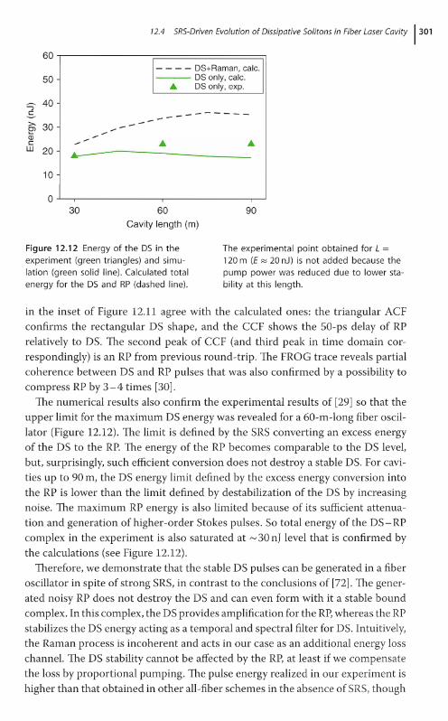
Figure 12.12 Energy of the DS in theexperiment (green triangles) and simulation (green solid line). Calculated totalenergy for the DS and RP (dashed line).
The experimental point obtained for L =120 m (E ~ 20 nJ) is not added because thepump power was reduced due to lower stability at this length.
in the inset of Figure 12.11 agree with the calculated ones: the triangular ACFconfirms the rectangular DS shape, and the CCF shows the 50-ps delay of RPrelatively to DS. The second peak of CCF (and third peak in time domain correspondingly) is an RP from previous round-trip. The FROG trace reveals partialcoherence between DS and RP pulses that was also confirmed by a possibility tocompress RP by 3-4 times [30].
The numerical results also confirm the experimental results of [29] so that theupper limit for the maximum DS energy was revealed for a 60-m-long fiber oscillator (Figure 12.12). The limit is defined by the SRS converting an excess energyof the DS to the RP. The energy of the RP becomes comparable to the DS level,but, surprisingly, such efficient conversion does not destroy a stable DS. For cavities up to 90 m, the DS energy limit defined by the excess energy conversion intothe RP is lower than the limit defined by destabilization of the DS by increasingnoise. The maximum RP energy is also limited because of its sufficient attenuation and generation of higher-order Stokes pulses. So total energy of the DS - RPcomplex in the experiment is also saturated at 1'./ 30 nJ level that is confirmed by
the calculations (see Figure 12.12).Therefore, we demonstrate that the stable DS pulses can be generated in a fiber
oscillator in spite of strong SRS, in contrast to the conclusions of [72]. The generated noisy RP does not destroy the DS and can even form with it a stable boundcomplex. In this complex, the DS provides amplification for the RP, whereas the RPstabilizes the DS energy acting as a temporal and spectral filter for DS. Intuitively,the Raman process is incoherent and acts in our case as an additional energy losschannel. The DS stability cannot be affected by the RP, at least if we compensatethe loss by proportional pumping. The pulse energy realized in our experiment ishigher than that obtained in other all-fiber schemes in the absence of SRS, though

3021 12 SRS-Driven Evolution of Dissipative Solitons in Fiber Lasers
SRS-induced energy conversion defines an upper limit for the DS energy andsubstantially changes the DS energy scalability.
In the next section, we show that the RP noise seen in Figure 12.11, can besuccessfully suppressed by the feedback loop, shown as a cloud-like inset inFigure 12.5.
12.4.2
Generation of Stokes-Shifted Raman Dissipative Solitons
In the previous section, we demonstrated that SRS in the fiber laser converts theexcess energy out of the coherent DS to a noisy Stokes-shifted RP thus limitingthe maximum DS energy [29, 30]. The RP noise is ascribed to the fact that it startsfrom spontaneous emission reaching high energy after only one round-trip of theDS, which acts as a pump for the RP. Because of the difference in group velocities,the RP afterwards runs away from the DS.
In this section, we study a possibility to initiate the Raman pulse not from noise,but from a seed pre-pulse provided by a feedback for the RP at proper timingdefined by the group velocity dispersion (see cloud-inset on Figure 12.5). As aresult, we have discovered that a feedback provided by re-injection of an RP intothe laser cavity leads to its transformation into a coherent RDS. Together, DS andRDS form a stable complex ofhigher total energy and broader spectrum than thoseof the DS alone.
If the pre-pulse is re-injected into a laser cavity with the proper amplitude, itwill then be synchronously amplified by the DS circulating in the cavity, similarto synchronous pumping mode-locking technique [79,82]. The difference in thegroup velocities of DS and RP is compensated by the bypass fiber of the feedbackloop providing a necessary delay for the RP.
To test the effect of the RP feedback on the pulse structure, we first did numerical simulations with the generalized NLSE 12.20 . The pulse shapes calculated withfeedback are shown in the diagrams of Figure 12.9. Evolution of the pulse temporaland spectral shapes along the cavity is shown in Figure 12.13. A stable noise-freeRP was found for the feedback coefficients R =Pf / P = 10-2 -10-6, where P is thecirculating light power with its small re-injected part Pf.
The RP and DS co-propagate together as one stable two-color complex. Foroscillator cavities longer than 80 m, the complex becomes unstable. In the range ofcavity lengths supporting the stable complex, increase of the pump power leads toa multipulse regime similar to conventional solitons [83 - 87]. Within each complex, the energy is nearly equally divided between the DS and the noise-free RP(see Figure 12.9, panel B in right column). The pulse evolution along the cavity(Figure 12.13) demonstrates how a stable noise-free RP is formed at the beginning of PMF due to conversion of the "red" part of the DS into the Stokes-shiftedwavelengths around 1060 nm. Then, the DS and RP separate due to dispersion.The delay line (DL) in the feedback loop compensates the dispersion shift and afterpartial outcoupling through ports D and E and amplifying in Yb3+ fiber, evolutionstarts again at point A. As can be seen (Figure 12.9), the feedback makes pulse

72.4 SRS-Driven Evolution of Dissipative Solitons in Fiber Laser Cavity1
303
-60 -50 -40 -30 -20 -10 0 (dB)
300 AB C PBS A B C PBS
250 1120
W 2001080
-S: 0..c 00,
Q) 150 cE Q)
i= 100 Q5 1040>~
50~
1000
00 10 20 30 40 0 10 20 30 40
(a) Distance (m) (b) Distance (m)
Figure 12.13 Evolution of the pulse shapesand spectra along the PMF and SMF (withthe active Yb3+-doped part) sections in ascheme of Figure 12.5 with the Raman feedback loop comprising the delay line (OL)
shown as the white box, with parameterssimilar to that in the experiment. PointsA, B, (, 0, E, and PBS (polarization beamsplitter) of the scheme of Figure 12.5 aremarked at the corresponding distances [31].
.-------======----------r 40
200
100
10~~~ 50~ -500 0 500
(]) 100 Time (fs):::>~
~20 ~o
-25030 'i:Y~~0
0..
0'"40 ~vo
0~o
50 v}(y-0 0 50 100 150 200 250
(a) (b) Time (ps)
Figure 12.14 Pulse shapes: (a) the simulatedfeedback-defined evolution of the intracavity pulses in the scheme of Figure 12.5(point B) versus the round-trip number.The zero time offset is bound to the position of the main dissipative soliton. (b)
The calculated OS and ROS pulse shapesinside the cavity (point B in Figure 12.5)and their instant frequencies. Inset: thedechirped OS-ROS complex with 70-psdelay compensation in the Raman feedbackloop [31].
evolution basically different (compare also Figure 12.10 with Figure 12.13). Thenoise is eliminated and the energy becomes concentrated in well-defined temporaland spectral ranges.
Figure 12.14a shows the transition from noise (the pre-pulse) to the steady-statepulse. In the initial state of the laser, amplification of noise starts at both fundamental and Raman wavelengths. Then, two chirped pulses are formed almostsimultaneously. The resulting complex of two bound dissipative solitons (the mainand Raman ones) circulates in the cavity in an extremely stable manner. The temporal shapes of stationary DS and RP are depicted in Figure 12.14b. Analysis ofthe RP spectral and temporal shape together with its spectral phase shown inFigure 12.14b led us to the conclusion that the noise-free RP realized numericallyin the scheme shown in Figure 12.5 can be called a RDS.
Based on the detailed comparison, we can conclude that the RDS realized in[31] has the same equilibrium characteristics and demonstrates similar evolution

304/ 12 SRS-Driven Evolution of Dissipative Solitons in Fiber Lasers
dynamics as the chirped pulses generated in the ANDi laser configuration agreedto be dissipative solitons [14, 19,88]. In addition to similar characteristics of theRDS and DS: temporal and spectral shapes, chirp and extracavity compressionfactors as well as their sensitivity to spectral filtering, the dissipative soliton natureof the coherent linearly chirped Raman pulse was also confirmed by a possibilityof its description in the frame of CQGLE (see [31] for details).
We presented above all the basic arguments including the solutions of the twomain equations in order to formulate unambiguously that the new stable Ramanshifted pulses are dissipative solitons. A fair comparison of NLSE and CGLE isa very demanding task, and we made only the first steps in this direction. Theapproximation of the uniformly distributed cavity relevant for CGLE is ratherrough for any laser generating dissipative solitons, since typical amplitude variation at point-action dissipative sections (gain, filtering, outcoupling, etc.) of thelaser cavity amount to about 1 order of magnitude, while temporal and spectralwidths may exhibit much smaller changes; see [19,20] and citations therein. Thesame is true for the new dissipative soliton generated via Raman process, wherethe amplitude variations are even stronger because of much higher Raman gainand lower feedback coefficient. The pulse widths are also slowly varying here, similar to that for conventional DS. We call a new soliton centered at 1060 nm a RamanDS in order to emphasize its origin leading to quantitative difference of the pulsedynamics from the main DS at similar qualitative behavior. The average characteristics of the DS and RDS are nearly the same and close to the dissipative solitonsolutions of CGLE.
12.4.2.1 Proof-of-Principle Experiment
To verify such promising theoretical predictions, we realized experimentallythe scheme shown in Figure 12.5 with feedback loop. The data presented inFigures 12.15 and 12.16 show that the pulses realized in the experiment arebasically different from those observed without feedback, but in good agreement
20 1- -------- Without feedback I20
"I I
EEc 0
c0
E Eco co:s gc c"U5 -20 "U5 -20c cQ) Q)
E E
Wavelength (nm)(a)
1000 1020 1040 1060 1080
(b)
1000 1020 1040 1060
Wavelength (nm)
1080
Figure 12.15 Output spectra: calculated (a)and measured (b) at the OS (blue) and ROSoutput (red) ports for the 40-m long cavitywith the feedback coefficient R = 10-4 andwithout feedback (gray). Note that the (i)
the spectral division between output portsin the experiment (rv 10 dB) is not as highas in the simulations (> 40 dB), and (ii) theROS port has significant spectral ripplesaround 1010nm [31].

12.4 SRS-Driven Evolution of Dissipative Solitons in Fiber Laser Cavity 1305
o 0
-RDS
50 100-50 0
Time(ps)
100 -100
(b)
50-50 0
Time (ps)
-os
O+---....~L£..-.--,--~~----I
-100
::j
~
:ffi 0.5c<D
E
(a)
2
Q5 4~oa..
8.,.-----;;---------.,...--------,
6 i::lTl~ ~
-0.2 0 0.2
Frequency (kHz)
-2 -1.5 -1 -0.5 0 0.5
(c) Time (ps)
1.5 -2 -1.5 -1 -0.5 0 0.5
(d) Time (ps)
1.5
Figure 12.16 Autocorrelation traces andradio frequency beating spectra of therealized pulses. The measured (points)autocorrelation traces of the OS (a) andROS (b), and the calculated (lines) forthe 40-m cavity oscillator with the feedback coefficient R = 10-4 . Inset: the corresponding FROG traces; Interferometric ACF
traces shown for OS (c) abd ROS (d) aftera double-pass compressor consisting of agrating pair. The compressor introducesone-pass group delay dispersion of 0 ~
-0.7 pS2. Insets: Radio frequency spectrameasured at a repetition rate of 5 MHz with1 Hz bandwidth [31].
with the RDS predicted by simulation. The RDS's spectrum has a typical shapewith steep edges, similar to the DS. The FROG trace (Figure 12.16) shows that thephases, pulse durations, and shapes of the DS and RDS are similar. The durationof the dechirped DS and RDS is measured to be 250-300fs and 300-400fs,correspondingly; see Figure 12.16c and d. The compression factor for the RDSis better than 100, that is, 1'-/30 times higher than that for the noisy RP in [29,30], and only slightly lower than that for the DS. The measured interferometricACF for the RDS has a contrast close to 8:1 (Figure 12.16c and d), only slightlydeviating from that for the dechirped DS. A radio frequency beat signal measuredat the fundamental repetition rate and its 150th harmonic are also similar forthe DS and RDS exhibiting a high contrast in the range of 60 -100 dB (see insetsin Figures 12.16c and d). These values are comparable with those for the 1'-/10 nJSRS-free DS generated in all-fiber configurations of Yb-doped fiber oscillators(see, e.g., [70]) and only slightly worse than the best results for the 1'-/3 nJ Er-dopedfiber oscillators [11]. In our case, the total pulse energy at the DS and RDS outputsis 25 nJ, with nearly equal division inside the cavity and a fourfold difference atthe outputs because of selective DS amplification.

3061 12 SRS-Driven Evolution of Dissipative Solitons in Fiber Lasers
The first-order RDS described earlier substantially differs from a classicalRaman soliton, which is a version of fundamental conservative soliton andappears as a result of the Raman frequency shift in the anomalous dispersionrange [79, 82], for example, in transmission lines [89]. As the RDS is bound withthe DS via a nonlinear Raman process, they are also different from one-color (Le.,of the same spectrum) bound solitons, or multisoliton complexes based on I(errnonlinearity [18,83-87]. In our case (see Figure 12.14b), the DS and RDS forma stable two-wavelength chirped DS complex that could be de-chirped into asingle pulse under certain conditions. The fringe pattern in Figure 12.14b (inset)results from merging of the compressed coherent DS and RDS pulses behindthe compressor. The fringe separation (rv 40 fs) is defined by the whole spectralrange of the solitonic DS + RDS complex, whose compressibility can be similarto the cases of nonlinear spectral broadening in fiber [79] or a Raman-activemode-locked laser [90]. It is worth noting that the fringe visibility, which showsthe coherence quality, depends on the feedback, with the highest coherencereached for the values 10-4 < R < 10-2• The results of simulation also show thatthe coherence of the RDS and DS is immune to noise variations in a broad range.
We also found that the shape of RDS is very sensitive to parameters of linearspectral filters, similar to that for conventional dissipative solitons. More detailedanalysis of RDS characteristics depending on cavity parameters is presented in thenext section.
12.4.3
Characteristics of Raman dissipative Solitons
In this section we analyze how the optical spectra of DS and RDS are sensitive tovariations of cavity parameters: linear and nonlinear (SRS-induced) filtering andthe Raman feedback loop.
12.4.3.1 Variation of the Soliton Spectra with Filter Parameters
Linear filtering is provided by two WDM couplers, whose spectra are sensitiveto temperature and can vary in the range of several nanometers. The first filter(marked as WDM1 in Figure 12.5) is a self-made PM-fiber coupler based on theinternal Lyot filter consisting of a properly oriented short PM-fiber piece anda PBS. Such a WDM coupler/splitter has a typical sinusoidal spectral function(Figure 12.17a) providing the wavelength division 1015/1060 nm for two outputcoupler arms. The second coupler (WDM2 in Figure 12.5 of the paper) is a commercial one having a stepwise transmission spectrum function with the cutoffat 1005 nm. The influence of the filtering effect of WDM1 on the DS is small,but nonlinear filtering becomes important due to strong Raman conversion,similar to that in the case of a noisy Raman pulse observed without WDM1 anddelay loop in [30]. As follows from our simulations, the SRS effect "eats" thelong-wavelength wing of the DS spectrum thus pushing the soliton spectrum outof the gain maximum (1025-1030 nm) toward the WDM2 -induced cutoff at 1005nm. This effect defines the short-wavelength edge of the generated spectrum.

12.4 SRS-Driven Evolution of Dissipative Solitons in Fiber Laser Cavity 1307
Wavelength (nm)
0.8
0.6
0.4
0.2
01000
(a)
1--WDM1 1--WDM2
1020 1040 1060 1080
Wavelength (nm)
20
IEc 0Eco:3-C.~ -20Q)
~
(b)
1000 1020 1040 1060 1080
Figure 12.17 (a) Transmission spectra of theWDM, and WDM2 couplers of the experimental scheme (Figure 12.5 of the paper).(b) Simulation results for the DS (blue)and RDS (red) spectra at different WDM,
coupler parameters: 1010/1055 nm (solid)and 1015/1060 nm (dashed) at the fixedWDM2 parameters (the cutoff wavelength at1005 nm), for 70 ps Raman delay and 1025(1030) nm gain maximum.
By numerically varying the exact position of the spectral maximum of theWDM1 filter (Figure 12.17a), we found that the RDS spectral width is verysensitive to these variations. As one can see in Figure 12.17b that a shift of only 5nm (the minimum value we can control in the experiment) leads to a significantchange of both the RDS position and width. Because the RDS spectrum obtainedwith the 1015/1060 nm filter fits better to the transmission function of the WDM1
coupler measured under the experimental conditions (Figure 12.17a), we usedthese data for comparing the calculated and experimental spectra (Figure 12.15).
12.4.3.2 Variation of the Soliton Spectra with the Raman Feedback Parameters
The maximum intracavity energy of the dissipative soliton depends on thefeedback value R = Pi jP logarithmically according to the equation for the SRSthreshold energy, Eth ~ In(ljR)6v-1 jgR' where 6v-1 = v;1- V~l is the inversegroup velocity difference of the DS and RDS, and gR is the Raman gain coefficient.The threshold energy for the experimental parameters is estimated as Eth rv 10nJ. Variation of the soliton spectral shape with the feedback coefficient inexperiment and simulation is presented in Figure 12.18. At the value R < 10-6,
the re-injected power Pi approaches the energy of the spontaneous emissionat the Stokes-shifted wavelength (Psp / P rv 10-7 ), and the feedback becomesinsufficient to overcome noise. At R > 10-2, the single DS + RDS complex splitsinto two similar pulse complexes separated in time. Stable pulses in 40-m cavityare realized for R = 10-2 -10-6 and delays in the range 50-80ps (with optimumat rv70 ps).
12.4.4
Generation of Multicolor Soliton Complexes and Their Characteristics
The scheme shown in Figure 12.5, with additional feedback loops can be used forgenerating next-order Stokes pulses of similar spectral and temporal shapes.

1-- R=-50dB I
1-- R=-70dBIo,..-.---------------,
-20
-40
-20
-60
-60
-80
-40
-80
-1 00 ..J........L..--,----r----~-______r--__,__J
0-..----------------,1-- R=-47dBI
1-- R=-70dBI
Experiment
o
-40
20
20
-40
'IEcEco~
C -20"00cQ)
E
'IEcE 0co~
"~ -20cQ)
E
3081 12 SRS-Driven Evolution of Dissipative Solitons in Fiber Lasers
Simulation
20 1-- R=-40dBI0-..------------------,
1-- R=-40dB I
-40
10801020 1040 1060
Wavelength ( nm)
-20
-80
-60
-40
-100...l........-'L...!..r------.-----I-1000 1020 1040 1060 1080 1000
Wavelength ( nm)
C -20"00cQ)
E
'IEc 0Eco~
Figure 12.18 Intracavity spectra in experiment and simulation corresponding to differentfeedback coefficients. The spectra are measured at point B of the scheme of Figure 12.5.
We numerically realized a scheme with two feedback loops, with the corresponding results shown in Figures 12.19 and 12.20. Figure 12.19 illustrates theevolution of the chirped pulse in the stable three-color regime. To realize it, wemade the following modifications of the scheme: (i) long (L ~ 80 m) PM fiber, (ii)two feedback loops, each of which comprises WDMiO splitter and 1 : RU) coupler(similar to the feedback loop in Figure 12.5) optimized for the first and secondStokes pulses (i = 1,2): R(I) = 10-4 , R(2) = 10-2. The regime becomes stable whenwe use, instead of sinusoidal WDM I (see Figure 12.17a), two special WDMil)
and WDMi2) splitters of a stepwise spectral function at cutoff wavelengths at1035 nm and 1085 nm, correspondingly. An implementation of such "hard"filters eliminates the remaining small-amplitude parts of the Raman pulse, whichcannot be fully suppressed in the case of a "soft" (sinusoidal) WDM I splitter(see Figure 12.13). Since each feedback loop operates independently, the scheme

12.4 SRS-Driven Evolution of Dissipative Solitons in Fiber Laser Cavity 1309
-60 -50 -40 -30 -20 -1 0 o (dB)
1120 .1I•••••Ii.II~1300
250
(j) 200S(1) 150Ef= 100
50
(a)
A
10 20
Distance (m)
30
B C PBS
40
1080..cOJc(1)
CD 1040~S
1000
(b)
A
o 10 20
Distance (m)
30
B C PBS
40
F
o
AlE
Figure 12.19 Evolution of the pulse shapes and spectra along the PMF and SMF sections ina scheme of Figure 12.5 in the case of two feedback loops providing delay and filtering forthe first and second Stokes waves with the additional output port F.
'I 30 osEc
0ECO~ -30C"00
-60cQ)
C-90
900 1000 1100
Wavelength (nm)
1200
Figure 12.20 Three-color bound solitons.Results of simulation for the generatedspectra in an 80-m-long PM-fiber cavityoscillator with the Raman feedbacks forthe first-order Stokes (R, = 10-4 ) and thesecond-order Stokes (R2 = 10-2 ) waves,in the presence of a band-stop filter at
1025 nm (10 nm width) and the followingparameters of the ith feedback loop: delaytime 140 ps (i = 1) and 280 ps (i = 2), stepwise WDM~j) couplers with cutoff wavelengths at 1035 nm (i = 1) and 1085 nm(i = 2).
offers a way to generate next Stokes orders by adding corresponding feedbackloops in a routine manner.
A number of optimization steps remain to be made in order to realize thisregime experimentally, including filter optimization. The open question iswhether one can realize experimentally first- and second-order RDSs withthe equidistant spectra shown in Figure 12.20. In this figure, one can see alsohigher-order noisy pulses at > 1150 nm as well as anti-Stokes components at< 1000 nm generated in frequency mixing processes.
It is significant that not only SRS, but also other nonlinear processes may beexplored for generating broadband multicolor dissipative soliton complexes.As demonstrated for the femtosecond solid-state lasers [90, 91], the combinedaction of SRS and four-wave mixing allow intracavity spectral broadening similarto the phenomenon of supercontinuum generation in fibers [92]. Successful
310 I 12 SRS~Driven Evolution of Dissipative Solitons in Fiber Lasers
pulse synthesis based on the total phase and spectrum control was recentlydemonstrated for several synchronized few-cycle lasers operating in differentspectral ranges [93] and for the light field synthesizer dealing with a coherentsupercontinuum from a single few-cycle laser [94]. Based on our approach,intracavity pulse synthesis looks feasible, with an important advantage: it will beintrinsically stable.
12.5
Conclusions and Future Developments
An important class of the soliton solutions of Ginzburg - Landau equation,so-called HCDSs, is extensively analyzed in this chapter. Strongly inhomogeneous phase across such solitons characterizes their capacity to redistributeenergy without loss of stability. This property provides energy scalability ofHCDS, feasible in femtosecond laser oscillators either with the cavity length oractive medium volume. The physical limitations of these steps are shown in theexample of all-fiber femtosecond fiber laser oscillators based on nonlinear polarization evolution mode-locking mechanism. The reason of the stability breakis an excessive rotation of polarization ellipse along the cavity [28]. The use ofpolarization-maintaining fibers allowed pushing further the cavity length limit. Alaser configuration based on long PM and short SM parts resulted in a total cavitylength of up to 120 m, with the following DS parameters: pulse energy> 20 n],the chirp parameter> 200 and a compressed pulse duration of 200 - 300 fs [29].
So-called master diagrams allow analysis of a complex laser operating in thepositive dispersion regime by decreasing the number of efficient system parameters of the Ginzburg - Landau equation. Based on master diagrams, it is shown thatlaser noise is another factor influencing the pulse energy of the laser [76]. Beingin its infancy, noise limitations of the maximal pulse energy are to be includedin forthcoming descriptions of high-energy femtosecond lasers. Technically, theproblem consists of determining the type and amplitude of noise.
For long laser cavities, a new limiting factor comes into play, namely SRS. Thedetailed analysis of the SRS-driven evolution of DS has been performed in framesof NSE in which the SRS term is added and the model has been compared withthe experiment [30]. It appears possible to realize a stable DS in the presenceof strong SRS. In general, the intrinsic Raman effect occurring in femtosecondfiber laser broaden our vision of the processes responsible for the pulse formation. One of its consequences is the appearance of a noisy Raman pulse linked tothe main DS. On one hand, because of high Raman gain, the noisy RP can lead tothe energy limitations of the main dissipative soliton. In principle, one or more RPscan reach energy comparable to that of the main DS. On the other, being properlytreated, RPs nevertheless allow to scale the cavity length and pulse energy up tohigh extend.
The pulse structure becomes quite different in case of feedback that delays anoisy RP at its every cavity round-trip [31]. Being properly built, such feedback

References 1311
leads to formation of a RDS instead of a noise Raman pulse in the feedback-freecase. The optimal feedback is very weak (R ~ 10-4 ) but it is enough to convertnoise into the coherent pulse due to high Raman gain. In this sense, it is sim-ilar to the weak random distributed feedback based on Rayleigh backscatteringconverting Raman amplified noise in fibers into the CW laser radiation [95, 96].
The results of numerical simulations of both DS and DS - RDS lasers based onSchr6dinger and Ginzburg - Landau equations are consistent with each other andwith the experiment. At high laser pump, the RDS energy can reach the energy ofthe main DS. The RDS occupies another spectral range thus reducing the Uenergycompetition" with the DS. At higher pump and in the presence of second feedback, second-order RDS can be generated. RDSs are coherent clones of the DS,with the residual noise comparable to the DS. As a result, they can be compressedexternally from tens of picoseconds to hundreds of femtoseconds pulses, similarto the DS. Though a laser with more than 100 m cavity is realized, the upper limitin terms of the pulse stability is still not reached.
Technically, the RDS approach reviewed in this book chapter allows for itsstraightforward extension to multi-RDS realization based on new fibers andfiber components. In principle, the approach offers a possibility of increasingthe intracavity ·complex energy by generating RDSs of different polarizations inother cavity loops having a common part with the main cavity. By the use ofdifferent fiber materials, one can vary spectral positions and spectral widths ofRDSs. By having a multi-RDS soliton complex with spectrally equidistant solitoncomponents and using a combination of SRS and four-wave mixing, a smoothultrabroadband spectrum looks feasible for its further compression in order togenerate single pulses of tens of femtoseconds and shorter.
Unique features of the soliton complexes demonstrated in the all-fiber schemesuch as high pulse energy, broad spectral range occupied by the complex,coherence of the solitons in the complex, offer new challenging applications.In medicine, coherence optical tomography and nonlinear or multiphotonfluorescence microscopy [97, 98] can benefit from broad high-power coherentspectrum. In both cases, high stability of the solitons will allow for collectingintrinsically weak signals from scattered light. Near-future high-bit rate periodictransmission lines with Raman pump can use more broadband and quiet lasersources based on soliton complexes demonstrated in this article. High power andlow noise [89] will allow for longer passive fiber pieces between the amplifiers.I(err nonlinearity could be considered as the mechanism that stabilizes thedissipative solitons in the complex. Alternatively, specialty fibers with properlydesigned dispersion for the main and frequency-shifted dissipative solitons canbe used.
Multicolor dissipative soliton complexes offer further extensions for frequencycomb spectroscopy [92, 99] and optical parametric amplification schemes (broadband seed) [100]; schemes for generating new spectral components in several synchronized enhancement cavities [101] containing a common nonlinear element,when each cavity is seeded by a certain RDS. Intrinsic stability and coherence ofthe complex will lead to a stable operation of the bundled enhancement cavities.

3121
72 SRS-Driven Evolution of Dissipative Solitons in Fiber Lasers
References
1. Duling, LN. III (1991) Subpicosecond Approaching the microjoule frontierall-fibre erbium laser. Electron. Lett., 27 with femtosecond laser oscillators: the-(6), 544-545. ory and comparison with experiment.
2. Fermann, M.E., Andrejco, M.J., Stock, New J Phys., 7, 217.M.L., Silberberg, Y., and Weiner, A.M. 13. Chong, A., Buckley, J.R., Renninger,(1993) Passive mode locking in erbium W.H., and Wise, EW. (2006) All-fiber lasers with negative group delay. normal-dispersion femtosecondAppl. Phys. Lett., 62 (9), 910-912. fiber laser. Opt. Express, 14 (21),
3. Nakazawa, M., Yoshida, E., and Kimura, 10-095-10-100.Y. (1993) Generation of 98 fs optical 14. Renninger, W.H., Chong, A., and Wise,pulses directly from an erbium-doped EW. (2008) Dissipative solitons infibre ring laser at 1.57 ~m. Electron. normal-dispersion fiber lasers. Phys.Lett., 29 (1), 63-65. Rev. A, 77 (2), 023 814/1-4.
4. Ilday, EO., Wise, EW., and Sosnowski, 15. Vanin, E., Korytin, A., Sergeev, A.,T.S. (2002) High-energy femtosecond Anderson, D., Lisak, M., and Vazquez,stretched-pulse fiber laser with a non- L. (1994) Dissipative optical solitons.linear optical loop mirror. Opt. Lett., 27 Phys. Rev. A, 49 (4), 2806-2811.(17), 1531-1533. 16. Kerner, B.S. and Osipov, V.V. (1994)
5. Lim, H., Ilday, EO., and Wise, EW. Autosolitons: A New Approach to(2003) Generation of 2-nJ pulses from a Problems of Self-Organization andfemtosecond ytterbium fiber laser. Opt. Turbulence, Kluwer Academic Publish-Lett., 28 (8), 660-662.
ers.6. Fernandez, A., Fuji, T., Poppe, A.,
17. Akhmediev, N. and Ankiewicz, A.Fiirbach, A., Krausz, E, and Apolonski,
(2005) Dissipative Solitons, LectureA. (2004) Chirped-pulse oscillators:
Notes in Physics, vol. 661, Springer-a route to high-power femtosecond
Verlag, Berlin.pulses without external amplification.Opt. Lett., 29 (12), 1366-1368.
18. Akhmediev, N. and Ankiewicz, A.
7. Haus, H.A., Tamura, K., Nelson, L.E.,(2008) Dissipative Solitons: From Optics
and Ippen, E.P. (1995) Stretched-pulseto Biology and Medicine, Springer-
additive pulse mode-locking in fiber Verlag.
ring lasers: theory and experiment. 19. Grelu, P. and Akhmediev, N.N. (2012)
IEEE J Quantum Electron., 31 (3), Dissipative solitons for mode-locked
591-598. lasers. Nat. Photonics, 6 (2), 84-92.
8. Ilday, EO., Buckley, J.R., Clark, W., and 20. Renninger, W.H. and Wise, EW. (2012)
Wise, EW. (2004) Self-similar evolution Dissipative soliton fiber laser, in Fiber
of parabolic pulses in a laser. Phys. Rev. Lasers (ed. O.G. Okhotnikov), John
Lett., 92 (21), 213 902/1-4. Wiley & Sons, Inc., pp. 97 -134.
9. Dudley, J.M., Finot, C., Richardson, 21. Haus, H.A. and Fellow, L. (2000)
D.J., and Millot, G. (2007) Self- Mode-Locking of Lasers. IEEE Jsimilarity in ultrafast nonlinear optics. Sel. Top. Quantum Electron., 6 (6),
Nat. Phys., 3 (9), 597 -603. 1173-1185.
10. Bale, B.G. and Wabnitz, S. (2010) 22. Buckley, J.R., Wise, EW., Ilday, EO.,
Strong spectral filtering for a mode- and Sosnowski, T.S. (2005) Femtosec-
locked similariton fiber laser. Opt. Lett., ond fiber lasers with pulse energies
35 (14), 2466-2468. above 10 nJ. Opt. Lett., 30 (14),
11. Oktem, B., Ulgudur., C., and Ilday, EO. 1888-1890.
(2010) Soliton-similariton fibre laser. 23. Chong, A., Renninger, W.H., and Wise,
Nat. Photonics, 4 (5), 307 -311. EW. (2007) All-normal-dispersion12. Kalashnikov, V.L., Podivilov, E., femtosecond fiber laser with pulse
Chernykh, A., Naumov, S., Fernandez, energy above 20 nJ. Opt. Lett., 32 (16),A., Graf, R., and Apolonski, A. (2005) 2408-2410.

References1
313
24. Lefranc;:ois, S., Kieu, K., Deng, Y., Kafl<a, 32. Newell, A.C. (1974) Nonlinear WaveJ.D., and Wise, EW. (2010) Scaling Motion, Lectures in Applied Mathemat-
of dissipative soliton fiber lasers to ics, voL 15, American Mathematical
megawatt peak powers by use of large- Society, Providence, RL
area photonic crystal fiber. Opt. Lett., 33. Komarov, K.P. (1986) Theory of sta-
35 (10), 1569-1571. tionary ultrashort pulses in solid-state
25. Soto-Crespo, J.M., Akhmediev, N.N., lasers with passive mode locking. Opt.
Afanasjev, V.V., and Wabnitz, S. (1997) Spektrosk., 60 (2), 379-384.
Pulse solutions of the cubic - quintic 34. Chernykh, A.L and Turitsyn, S.K.
complex Ginzburg - Landau equation (1995) Soliton and collapse regimes of
in the case of normal dispersion. Phys. pulse generation in passively mode-
Rev. E, 55 (4), 4783-4796.locking laser systems. Opt. Lett., 20 (4),398-400.
26. Podivilov, E.V. and Kalashnikov, V.L.Salhi, M., Haboucha, A., Leblond, H.,
(2005) Heavily-chirped solitary pulses35.
and Sanchez, E (2008) Theoreticalin the normal dispersion region: new
study of figure-eight all-fiber laser.solutions of the cubic - quintic complex Phys. Rev. A, 77 (3), 033 828/1- 9.Ginzburg - Landau equation. JETP Lett.,
36. Grtac;:, B., Baumgard, M., Limpert, J.,82 (8),467 -471. and Tilnnermann, A. (2009) Approach-
27. Kharenko, D.S., Shtyrina, G.V., ing microjoule-level pulse energy withYarutkina, LA., Podivilov, E.V., Fedoruk, mode-locked femtosecond fiber lasers.M.P., and Babin, S.A. (2011) Highly Opt. Lett., 34 (10), 1585 -1587.chirped dissipative solitons as a one- 37. Naumov, S., Fernandez, A., Graf, R.,parameter family of stable solutions of Dombi, P., Krausz, E, and Apolonski,the cubic - quintic Ginzburg - Landau A. (2005) Approaching the micro-equation. f. Opt. Soc. Am. B, 28 (10), joule frontier with femtosecond laser2314-2319. oscillators. New f. Phys., 7, 216-216.
28. Kharenko, D.S., Shtyrina, G.V., 38. Leblond, H., Salhi, M., Hideur, A.,
Yarutkina, LA., Podivilov, E.V., Fedoruk, Chartier, T., BruneI, M., and Sanchez,
M.P., and Babin, S.A. (2012) Generation E (2002) Experimental and theoretical
and scaling of highly-chirped dissipative study of the passively mode-locked
solitons in an Yb-doped fiber laser. ytterbium-doped double-clad fiber
Laser Phys. Lett., 9 (9), 662-668. laser. Phys. Rev. A, 65 (6), 063 811/1-9.
29. Kharenko, D.S., Podivilov, E.V., 39. Komarov, A., Leblond, H., and
Apolonski, A.A., and Babin, S.A. (2012) Sanchez, E (2005) Quintic complex
20 nJ 200 fs all-fiber highly-chirped Ginzburg - Landau model for ring
dissipative soliton oscillator. Opt. Lett., fiber lasers. Phys. Rev. E, 72 (2), 025
37 (19),4104-4106.604/1-4.
40. Bale, B.G., Kutz, J.N., Chong, A.,30. Bednyakova, A.E., Babin, S.A.,
Renninger, W.H., and Wise, EW. (2008)Kharenko, D.S., Podivilov, E.V.,
Spectral filtering for high-energy mode-Fedoruk, M.P., Kalashnikov, V.L.,
locking in normal dispersion fiberand Apolonski, A. (2013) Evolution lasers. f. Opt. Soc. Am. B, 25 (10), 1763.of dissipative solitons in a fiber laser 41. Akhmediev, N.N., Eleonskii, V.M., andoscillator in the presence of strong Kulagin, N.E. (1987) Exact first-orderRaman scattering. Opt. Express, 21 solutions of the nonlinear Schrodinger(18), 20556. equation. Theor. Math. Phys., 72 (2),
31. Babin, S.A., Podivilov, E.V., Kharenko, 809-818.D.S., Bednyakova, A.E., Fedoruk, M.P., 42. Soto-Crespo, J.M., Akhmediev, N.N.,Kalashnikov, V.L., and Apolonski, and Afanasjev, V.V. (1996) Stability ofA. (2014) Multicolour nonlinearly the pulselike solutions of the quinticbound chirped dissipative solitons. Nat. complex Ginzburg - Landau equation.Commun., 5, 4653. f. Opt. Soc. Am. B, 13 (7), 1439-1449.

3141
72 SRS-Driven Evolution of Dissipative Solitons in Fiber Lasers
43. Soto-Crespo, J.M., Akhmediev, N.N., 55. Tang, D.Y., Zhao, L.M., Zhao, B., andand Town, G. (2002) Continuous-wave Liu, A.Q. (2005) Mechanism of mul-versus pulse regime in a passively tisoliton formation and soliton energymode-locked laser with a fast saturable quantization in passively mode-lockedabsorber. f. Opt. Soc. Am. B, 19 (2), fiber lasers. Phys. Rev. A, 72 (4), 043234-242. 816/1-9.
44. Kalashnikov, V., Podivilov, E., 56. Chong, A., Liu, H., Renninger, W.H.,Chernykh, A., and Apolonski, A. (2006) and Wise, EW. (2008) FemtosecondChirped-pulse oscillators: theory and erbium-doped fiber lasers with largeexperiment. Appl. Phys. B, 83 (4), normal cavity dispersion. 2008 Con-503-510. ference on Lasers and Electro-Optics,
45. Kalashnikov, V.L. and Apolonski, A. IEEE, pp. 1-2.(2009) Chirped-pulse oscillators: a uni- 57. Kobtsev, S.M. and Smirnov, S.V. (2011)fied standpoint. Phys. Rev. A, 79 (4), Fiber lasers mode-locked due to non-043 829/1-10. linear polarization evolution: Golden
46. Kalashnikov, V.L. (2009) Chirped mean of cavity length. Laser Phys., 21dissipative solitons of the com- (2), 272-276.plex cubic - quintic nonlinear 58. Boyd, R.W. (2003) Nonlinear Optics,Ginzburg - Landau equation. Phys. 2nd edn, Academic Press, San Diego,Rev. E, 80 (4), 046 606/1-8. CA.
47. Ablowitz, M. and Horikis, T. (2009) 59. Ding, E., Lefranc;:ois, S., Kutz, J.N., andSolitons in normally dispersive mode- Wise, EW. (2011) Scaling fiber laserslocked lasers. Phys. Rev. A, 79 (6), to large mode area: an investigation of063845. passive mode-locking using a multi-
48. Mathews, J. and Walker, R.L. (1964) mode fiber. IEEE f. Quantum Electron.,Mathematical Methods of Physics, 47 (5), 597 -606.Benjamin. 60. Chong, A., Renninger, W.H., and Wise,
49. Chang, W., Ankiewicz, A., Soto-Crespo, EW. (2008) Environmentally stableJ., and Akhmediev, N. (2008) Dissipa- all-normal-dispersion femtosecond fibertive soliton resonances. Phys. Rev. A, 78 laser. Opt. Lett., 33 (10), 1071-1073.(2), 023 830/1- 9. 61. Jiang, K., Ouyang, C., Shum, P.P., Wu,
50. Akhmediev, N., Soto-Crespo, J., and K., and Wong, J.H. (2012) High-energyGrelu, P., (2008) Roadmap to ultra- dissipative soliton with MHz repetitionshort record high-energy pulses out of rate from an all-fiber passively mode-laser oscillators, Phys. Lett. A, 372 (17), locked laser. Opt. Commun., 285 (9),3124-3128. 2422-2425.
51. Ding, E., Grelu, P., and Kutz, J.N., 62. Kobtsev, S.M., Kukarin, S.V., Fedotov,(2011) Dissipative soliton resonance Y.S., and Ivanenko, A.V. (2011) High-in a passively mode-locked fiber laser, energy femtosecond 1086/543-nm fiberOpts. Lett., 36 (7), 1146-1148. system for nano- and micromachining
52. Renninger, W.H., Chong, A., and Wise, in transparent materials and on solidEW. (2008) Giant-chirp oscillators for surfaces. Laser Phys., 21 (2), 308-311.short-pulse fiber amplifiers. Opt. Lett., 63. Kobtsev, S.M., Kukarin, S., and33 (24), 3025-3027. Fedotov, Y.S. (2008) Ultra-low repe-
53. Wise, EW., Chong, A., and Renninger, tition rate mode-locked fiber laser withW.H. (2008) High-energy femtosecond high-energy pulses. Opt. Express, 16fiber lasers based on pulse propagation (26),21-936-21-941.at normal dispersion. Laser Photonics 64. Kelleher, E.J.R., Travers, J.C., Ippen,Rev., 2 (1- 2), 58 - 73. E.P., Sun, Z., Ferrari, A.C., Popov, S.V.,
54. Kalashnikov, V.L. and Chernykh, A.I. and Taylor, J.R. (2009) Generation and(2007) Spectral anomalies and stability direct measurement of giant chirp in aof chirped-pulse oscillators. Phys. Rev. passively mode-locked laser. Opt. Lett.,A, 75 (3), 033 820/1-5. 34 (22), 3526-3528.

References1
315
65. Nyushkov, B., Denisov, V., Kobtsev, soliton oscillator and its scaling. SPIE5., Pivtsov, V., Kolyada, N., Ivanenko, Proc., 8601, 86 012H-86 012H-6.A., and Turitsyn, S. (2010) Genera- 75. Schadt, D. and Jaskorzynska, B. (1987)tion of 1.7-I'J pulses at 1.55 I'm by a Frequency chirp and spectra due toself-made-locked all-fiber laser with a self-phase modulation and stimulatedkilometers-long linear-ringcavity. Laser Raman scattering influenced by pulsePhys. Lett., 7 (9), 661-665. walk-off in optical fibers. f. Opt. Soc.
66. Koliada, N.A., Nyushkov, B.N., Am. B, 4 (5), 856-862.Ivanenko, A.V., Kobtsev, S.M., Harper, 76. Kalashnikov, V.L. (2014) DissipativeP., Turitsyn, S.K., Denisov, V.I., and solitons in presence of quantum noise.Pivtsov, V.S. (2013) Generation of Chaotic Model. Simul., 1, 29-37.dissipative solitons in an actively mode- 77. Turitsyn, S.K., Bale, B.G., and Fedoruk,locked ultralong fibre laser. Quantum M.P. (2012) Dispersion-managed soli-Electron., 43 (2), 95 - 98. tons in fibre systems and lasers. Phys.
67. Nielsen, C.K., Orta<;:, B., Schreiber, Rep., 521 (4), 135 - 203.T., Limpert, J., Hohmuth, R., Richter, 78. Blow, K. and Wood, D. (1989) Theoret-W., and Tiinnermann, A. (2005) Self- ical description of transient stimulatedstarting self-similar all-polarization Raman scattering in optical fibers.maintaining Yb-doped fiber laser. Opt. IEEE f. Quantum Electron., 25 (12),Express, 13 (23), 9346-9351. 2665-2673.
68. Schultz, M., Karow, H., Prochnow, 0., 79. Agrawal, G.P. (2007) Nonlinear FiberWandt, D., Morgner, D., and Kracht, D. Optics, Academic Press.(2008) All-fiber ytterbium femtosecond 80. Hollenbeck, D. and Cantrell, C.D.laser without dispersion compensation. (2002) Multiple-vibrational-modeOpt. Express, 16 (24), 19-562-19-567. model for fiber-optic Raman gain spec-
69. Mortag, D., Wandt, D., Morgner, D., trum and response function. f. Opt.Kracht, D., and Neumann, J. (2011) Soc. Am. B, 19 (12), 2886-2892.Sub-80-fs pulses from an all-fiber- 81. Trebino, R. (2002) Frequency-Resolvedintegrated dissipative-soliton laser at 1 Optical Gating: The MeasurementI'm. Opt. Express, 19 (2), 546-551. of Ultrashort Laser Pulses, Springer-
70. Zhao, L.M., Bartnik, A.C., Tai, Q.Q., Verlag.and Wise, EW. (2013) Generation of 82. Akhmanov, S.A., Vysloukh, V.A., and8 nJ pulses from a dissipative-soliton Chirkin, A.S. (1992) Optics of Femtosec-fiber laser with a nonlinear optical loop ond Laser Pulses, AlP, New York.mirror. Opt. Lett., 38 (11), 1942-1944. 83. Grelu, P. and Akhmediev, N. (2004)
71. Erkintalo, M., Aguergaray, C., Runge, Group interactions of dissipative soli-A., and Broderick, N.G.R. (2012) Envi- tons in a laser cavity: the case of 2+1.ronmentally stable all-PM all-fiber giant Opt. Express, 12 (14), 3184-3189.chirp oscillator. Opt. Express, 20 (20), 84. Stratmann, M., Pagel, T., and Mitschke,22 - 669 - 22 - 674. E (2005) Experimental observation of
72. Aguergaray, C., Runge, A., Erkintalo, temporal soliton molecules. Phys. Rev.M., and Broderick, N.G.R. (2013) Lett., 95 (14), 143902.Raman-driven destabilization of 85. Komarov, A., Leblond, H., and Sanchez,mode-locked long cavity fiber lasers: E (2005) Multistability and hysteresisfundamental limitations to energy scal- phenomena in passively mode-lockedability. Opt. Lett., 38 (15), 2644-2646. fiber lasers. Phys. Rev. A, 71 (5),
73. Kieu, K., Renninger, W.H., Chong, A., 053809.and Wise, EW. (2009) Sub-100 fs pulses 86. Tang, D., Zhao, L., and Zhao, B. (2004)at watt-level powers from a dissipative- Multipulse bound solitons with fixedsoliton fiber laser. Opt. Lett., 34 (5), pulse separations formed by direct soli-593-595. ton interaction. Appl. Phys. B, 80 (2),
74. Kharenko, D.S., Podivilov, E.V., 239-242.Apolonski, A.A., and Babin, S.A. (2013) 87. Jang, J.K., Erkintalo, M., Murdoch,All-fiber highly-chirped dissipative S.G., and Coen, S. (2013) Dltraweak

3161 12 SRS-Driven Evolution of Dissipative Solitons in Fiber Lasers
long-range interactions of solitonsobserved over astronomical distances.Nat. Photonics, 7 (8), 657 -663.
88. Chong, A., Renninger, W.H., and Wise,EW. (2008) Properties of normaldispersion femtosecond fiber lasers. f.Opt. Soc. Am. B, 25 (2), 140-148.
89. Kumar, S. and Hasegawa, A. (1995)Suppression of the Gordon - Haus noiseby a modulated Raman pump. Opt.Lett., 20 (18), 1856-1858.
90. Sorokin, E., Kalashnikov, V., Naumov,S., Teipel, J., Warken, E, Giessen, H.,and Sorokina, I. (2003) Intra- andextra-cavity spectral broadening andcontinuum generation at 1.5 j1.m usingcompact low-energy femtosecondCr:YAG laser. Appl. Phys. B, 77 (2-3),197-204.
91. Sander, M.Y., Ippen, E.P., andKartner, EX. (2010) Carrier-envelopephase dynamics of octave-spanningdispersion-managed Ti: sapphire lasers.Opt. Express, 18 (5), 4948-4960.
92. Dudley, J.M. and Coen, S. (2006)Supercontinuum generation in photoniccrystal fiber. Rev. Mod. Phys., 78 (4),1135-1184.
93. Cox, J.A., Putnam, W.P., Sell, A.,Leitenstorfer, A., and Kartner, EX.(2012) Pulse synthesis in the singlecycle regime from independentmode-locked lasers using attosecondprecision feedback. Opt. Lett., 37 (17),3579-3581.
94. Wirth, A., Hassan, M.T., Grguras, 1.,Gagnon, J., Moulet, A., Luu, T.T., Pabst,S., Santra, R., Alahmed, Z.A., Azzeer,A.M., Yakovlev, V.S., Pervak, V., Krausz,E, and Goulielmakis, E. (2011) Synthesized light transients. Science (NewYork), 334 (6053), 195-200.
95. Turitsyn, S.K., Babin, S.A., El-Taher,A.E., Harper, P., Churkin, D.V.,Kablukov, S.I., Ania-Castafion, J.D.,Karalekas, V., and Podivilov, E.V. (2010)Random distributed feedback fibrelaser. Nat. Photonics, 4 (4), 231-235.
96. Turitsyn, S.K., Babin, S.A., Churkin,D.V., Vatnik, I.D., Nikulin, M., andPodivilov, E.V. (2014) Random distributed feedback fibre lasers. Phys.Rep., 542 (2), 133 -193.
97. Ishikawa-Ankerhold, H.C., Ankerhold,R., and Drummen, G.P.C. (2012)Advanced fluorescence microscopytechniques-FRAP, FLIP, FLAP,FRET and FLIM. Molecules, 17 (4),4047-132.
98. Xu, C. and Wise, EW. (2013) Recentadvances in fiber lasers for nonlinearmicroscopy. Nat. Photonics, 7, 875.
99. Schibli, T.R., Hartl, I., Yost, D.C.,Martin, M.J., MarcinkeviCius, A.,Fermann, M.E., and Ye, J. (2008) Optical frequency comb with submillihertzlinewidth and more than 10 W averagepower. Nat. Photonics, 2 (6), 355-359.
100. Cerullo, G. and De Silvestri, S. (2003)Ultrafast optical parametric amplifiers.Rev. Sci. Instrum., 74 (1), 1.
101. Pupeza, I., Holzberger, S., Eidam, T.,Carstens, H., Esser, D., Weitenberg,J., RuBbilldt, P., Rauschenberger, J.,Limpert, J., Udem, T., Tilnnermann, A.,Hansch, T.W., Apolonski, A., Krausz,E, and Fill, E. (2013) Compact highrepetition-rate source of coherent 100eV radiation. Nat. Photonics, 7 (8),608-612.