(12) united states patent (10) patent no.: us 9,428,202 b221) appl. no.: 14/466,000 340,989 * cited...
TRANSCRIPT

USOO94282O2B2
(12) United States Patent (10) Patent No.: US 9,428,202 B2 Perras et al. (45) Date of Patent: Aug. 30, 2016
(54) TRAIN SAFETY SYSTEM (2013.01); B61L 15/0072 (2013.01); B61L 27/0022 (2013.01); B61L 27/0027 (2013.01);
(71) Applicant: VIA Rail Canada Inc., Montréal (CA) G0IS 19/14 (2013.01); B61L 23/00 (2013.01) (58) Field of Classification Search
(72) Inventors: Claude Perras, Oka (CA); Leigh None Thorpe, Ottawa (CA); Francois See application file for complete search history. Blouin, Gatineau (CA)
(56) References Cited (73) Assignee: Via Rail Canada Inc., Montreal,
Quebec (CA) U.S. PATENT DOCUMENTS
(*) Notice: Subject to any disclaimer, the term of this 2009/014684.6 A1* 6/2009 Grossman ............... B605, patent is extended or adjusted under 35 2012/0033123 A1 2/2012 Inoue ....................... GO8G 1.04 U.S.C. 154(b) by 134 days. 348,333.13
2014/0218218 A1* 8, 2014 Lloreda ................. EOSB 39,005 (21) Appl. No.: 14/466,000 340,989
* cited by examiner (22) Filed: Aug. 22, 2014
O O Primary Examiner — Adam Alharbi (65) Prior Publication Data (74) Attorney, Agent, or Firm — Nixon Peabody LLP
US 2015/O29 1193 A1 Oct. 15, 2015 (57) ABSTRACT
Related U.S. Application Data A method and system for assisting the safe operation of a (60) Provisional application No. 61/979,692, filed on Apr. train adapted to be operated by a locomotive operating crew
15, 2014. comprises generating GPS-located critical information at a central location, the GPS-located critical information being
(51) Int. Cl. based at least in part on one or more railroad maps and one G05D I/O (2006.01) or more train dispatcher information systems; monitoring B6L 25/02 (2006.01) the real-time location of the train with a GPS device on B6IL IS/00 (2006.01) board the train; and generating alerts for the locomotive B6L 27/00 (2006.01) operating crew based on the GPS-located critical informa GOIS 19/4 (2010.01) tion and the real time location of the train, so that the crew B6IL 2.3/OO (2006.01) is alerted as to upcoming changes to be implemented.
(52) U.S. Cl. CPC .......... B61L 25/025 (2013.01); B61L 15/0027 17 Claims, 14 Drawing Sheets
M is is splication 106 - rs at . . user interface f -121 '.
writerace É A: Enterface -----
centerface Hir-r centerface re front
a898te | ifiesiace
f:3ck Maiage:ng it Syssa
f
s
3
i O Raiia iwisp Track
w Catalase)

U.S. Patent Aug. 30, 2016 Sheet 1 of 14 US 9,428,202 B2
TSS Appication
}se frterface
terface
Certerface ..."" Cat iterace
air Cottro rteface
Satelite iterface
rain Cotto: interface
C. interface
2.
test
SS Centra Sysien
rack waagement System
Railway wag tack
Database
U.S. Patent Aug. 30, 2016 Sheet 2 of 14 US 9,428,202 B2
s 2
- - - - y-/ r or r - -.
n , TSS Application TSS Central System's. i35 - v. rack
was ageinent System
-- rain Dispatchers
v
s
i i \ 282
Desktop 22
B. --- E vanagement vam - Y 23
tip. Stats. 25. - - Perforate 226
N Reice 24.
8, 2

U.S. Patent Aug. 30, 2016 Sheet 3 of 14 US 9,428,202 B2
ack vanagement
System Railway wap
F. 3

U.S. Patent Aug. 30, 2016 Sheet 4 of 14 US 9,428,202 B2
400 . f
N OGNSREE v.
BAE: O is flyw O9 fYY 34 i RA; ; ; i "RA8 ORiG: yONTREA 8. C.
TRAiN DESS: AFAX, NS N
S.
E.P.O.YE WERS: PASSWORD: ; : IgE: XX000000 iCE:................... i
E: YY333i: i.E. 42
7 i - F. - ... - . - - - ,y
LocoMOTIVES) No.: : 54 54. s 3:38, :8:
r
CARS: HEP BC: REN: 3 (THER: : ; ONS: 1999
SS: 1300 t v. SEE: P+ .'
w a w
FG. 4

U.S. Patent Aug. 30, 2016 Sheet S of 14 US 9,428,202 B2
er s
SCO GBC CONFORWY WERCAON SCREEN a N.' DC C CERAE SYSE - G3C S MSSG R ERROES v.
CAAAYANA RAAY ERE
v FRIDAY iA8 ARY 3,2034 X SBC No. 8s. X
TO: NO 53 AT: VA MORTREA OF AWA X
AAB. N.S.--YACN-E SE 2.25 X REASE E2 X
KNGSCBS - 3 O2 X AEXA RASB E 84. x
's WALLEYFIELDSUB MILE 45 to 47.2 X ra
s S
F.G. 5

U.S. Patent Aug. 30, 2016 Sheet 6 of 14 US 9,428,202 B2
60 692 803 arareer areaarea
B ...;
t
as . . . 29,482 r 3 3S
E888:8:88-8: ...-
88.88. 8.8 S288:88-88: 888 is
R.: 4:28:8-4s-88 N38: iri : ------------- 88:
612 F. 6A F. S3
8; 8.

U.S. Patent Aug. 30, 2016 Sheet 7 of 14 US 9,428,202 B2
- - - - - - - - - - - - - - - - - - - - - - - - - - - - - - - - - - - - - - - - - - - - - - - - - - - - - - - - res,
Vanua Restriction input Screen - location identification
Skivisit?: Alexandria y: S.8 Statio get certscar
P frost: 3:
East Switch West Switch South SWitch
Cai Forenian nam-m-m-m-m-m-m-m-m-m-m-m-m-m-m-m-m-m-m-m-m-m-m-
Leaving inits 5 mph 50 aph
FCC
North Switch
STOP
Stop 3 Protect Highway Xing a RC i0 ingh 60 figh
CaS 20 gh 70 righ Stop untical foremain
respasser on of rear track 3. ph 8 Frigh CaC
Report Switch
structier High Water 40 mph 30 nigh r of Track
Sippery Rai w W.
s As
F. 7

U.S. Patent
36 - Systern start
23: Shack
Syster data
----- logi 804
3OS ---
3S ---/
Successful system check?
Confirm info Conformity * --
8. {with paper copies
833 - N -f 1
arch Operational
8ge
Aug. 30, 2016
Eispiay warning isgay instructions
airch exception iaiding
F. 8
Sheet 8 of 14
Risplay error info Risplay
Strictions
--- 34
US 9,428,202 B2

U.S. Patent Aug. 30, 2016 Sheet 9 of 14 US 9,428,202 B2
SO -- SAR
perationa: Wode
902 -- S2 GPS locati
and Speed
1 -1
-- S04 Calciate ? Schedule -------
Adherence |-905
/
inciate Contextuai --- Risplay Corponents
c. Syer keeae
--93S -1 Compare ---
Waypoints vs. locatio
Everts -38 riggered
isitay Railway Procedurai for nation
-- 98
launch trip Case
de
REG, 9

U.S. Patent Aug. 30, 2016 Sheet 10 of 14
8.
SAR
rip Close wode
Erip Close CEB2
pload rip formation
Close System 34
FG
US 9,428,202 B2
U.S. Patent
irstructions ------
83. rosea
instructions
Aug. 30, 2016
input by to
FG.
Sheet 11 of 14
-------
US 9,428,202 B2
2
/ ? --
Determine Most f Eax Speed f : Restrictive tax i &
Speed -...-b; GPS-located & applicatie SPS f critica
: casts f stirratic

U.S. Patent Aug. 30, 2016 Sheet 12 of 14 US 9,428,202 B2
20 &^
3: & & 8:8:
^. 8 ^ * No 1...NCY X 88: 838 X N 1
F. 2

U.S. Patent Aug. 30, 2016 Sheet 13 of 14
^: $888: 8888 eterie extent species - look-ahead for 88-888 current speed
Y. 8888te 88 spe:8: *-x axes at 8:x:y w8.
XK-888
i current speed, £888 8888. xex as: 88 8x
- train, etc. , &8k-38883 w8xxx -
Y------------------------------------&
:
: y * *. 88.88% 3. -888: 8888 : 8:8; : -
: Mixx. 888 & 8888 jocation ^88: 8888.*
888 & A A A A A A A A A A A A A A. A . . . . . . . . . . . . . . . . .
f : a
^XM83:
Fig. 3
US 9,428,202 B2
ise faking cisive tax as tax permissile speed
st first
.8333

U.S. Patent Aug. 30, 2016 Sheet 14 of 14 US 9,428,202 B2
xxxix-axe3e skitix: E X
- - - - - - - - - - - - - - - - - - - - - - - - - - - - - - - - - - - - - - - - - - - - - - - - - - - - - - - - - - - - - - - - - - - - - - - - - - - - - - - - - - - - - - - - - -
S. a
S 3:star:ce axg track. into 3.
4:4.
FG 4

US 9,428,202 B2 1.
TRAIN SAFETY SYSTEM
CROSS REFERENCE TO RELATED APPLICATIONS
This application claims the benefit of U.S. Provisional Application No. 61/979,692, filed Apr. 15, 2014, which is hereby incorporated by reference herein in its entirety.
FIELD OF THE INVENTION
The present disclosure relates to railway systems and, more particularly, to a train safety system.
SUMMARY
In accordance with one embodiment, a method of assist ing the safe operation of a train adapted to be operated by a locomotive operating crew comprises (a) generating GPS located critical information at a central location, the GPS located critical information being based at least in part on one or more railroad maps and one or more train dispatcher information systems; (b) monitoring the real-time location of the train with a GPS device on-board the train; and (c) generating alerts for the locomotive operating crew based on the GPS-located critical information and the real time loca tion of the train, so that the crew is alerted as to upcoming changes to be implemented.
In accordance with another embodiment, a safety system safety system for a train having a locomotive operating crew comprises (a) a database containing one or more railroad maps and one or more train dispatcher information systems: (b) a central server adapted to be at least intermittently coupled to the database to generate GPS-located critical information; (c) a GPS device on-board the train to monitor the real-time location of the train; and (d) a computer on-board the train and adapted to be at least intermittently coupled to the central server and the GPS device for execut ing an application utilizing the GPS-located critical infor mation and the real-time location of the train, wherein the application generates alerts for the locomotive operating crew based on the GPS-located critical information and the real time location of the train, so that the crew is alerted as to upcoming changes to be implemented.
The foregoing and additional aspects and embodiments of the present disclosure will be apparent to those of ordinary skill in the art in view of the detailed description of various embodiments and/or aspects, which is made with reference to the drawings, a brief description of which is provided neXt.
BRIEF DESCRIPTION OF THE DRAWINGS
FIG. 1 is the Train Safety System overview. FIG. 2 is the Train Safety System context diagram. FIG. 3 is a conceptual view of the Train Safety System. FIG. 4 is the Train Safety System Application Initializa
tion Screen. FIG. 5 is the TSS Application Conformity Verification
Screen. FIG. 6A shows a TSS Application primary operating
display. FIG. 6B shows a TSS Application primary operating
display. FIG. 7 is the Manual Restriction Input Screen. FIG. 8 is the System Initialization Flow Chart. FIG. 9 is the System Operational Mode Flow Chart.
10
15
25
30
35
40
45
50
55
60
65
2 FIG. 10 is the Trip Close Mode Flow Chart. FIG. 11 shows an example of the information flow to
calculate maximum speed and GPS-located critical infor mation.
FIG. 12 shows a logic process to display information. FIG. 13 shows a logic process to look-ahead for upcoming
speed. FIG. 14 shows an example of a breaking curve with
look-ahead. While the present disclosure is susceptible to various
modifications and alternative forms, specific embodiments or implementations have been shown by way of example in the drawings and will be described in detail herein. It should be understood, however, that the disclosure is not intended to be limited to the particular forms disclosed. Rather, the disclosure is to cover all modifications, equivalents, and alternatives falling within the spirit and Scope of an inven tion as defined by the appended claims.
DETAILED DESCRIPTION
The Train Safety System (TSS) is a system designed to help the locomotive operating crew (LOC) (comprising In-Charge Locomotive Engineer, Locomotive Engineer, train driver, train conductor or train driver assistant, train driver trainee, or any person involved in operating the train) with driving the train and to reduce the risk of losing geographical reference (being unsure of the location of the train along the route), missing a signal, over speeding, or losing track of any other restriction (i.e., work Zone, author ity limits), any of which could lead to a severe accident. The system can be classified as a safety overlay on the existing railway operating procedures and safety systems and can be deployed without requiring additional capabilities on the railroad infrastructure (e.g. new transponders). The system is based on ICT (Information and Communication Technol ogy). The system applies ICT and human factors design to reduce the cognitive and memory demands on the locomo tive driver, as well as to mitigate the consequences of human error in the operation of the train.
Referring to FIG. 1, the TSS 100 comprises a Central System or central information server 102 communicating with one or more trains 101a ... 101 in over the Internet 103 or private data network. Each train 101a, 101b . . . 101n is equipped with one or more in-cabin devices executing the in-cabin TSS application 106a ... 106n. The TSS Applica tion 106a . . . 106n uses one or more wireless interface(s) 121, such as cellular (3G, 4G, LTE or other cellular data communication capability), WIFI or a satellite interface 122, or a combination thereof to connect to the Internet 103 or any other means of connecting to the Internet 103. The TSS Application 106a . . . 106.n may include a train control interface 120 to optionally perform functions directly on the train controls. The central information server 102 interfaces with existing track management systems 104. In order to work on different railways, independent of the railroad infrastructure, including where the trip crosses railway juris dictions, the TSS 100 uses a database 105 (track database) containing a detailed base map of the contemplated rail ways, a geo-positioning (GPS coordinates) along with asso ciated milepost of all the elements which could affect the movement of trains, a braking calculator, and a set of predefined alerts. The TSS central information server retrieves, stores, and updates operational information 107 such as the Railway Operating Rules, General Bulletin Orders (GBO), Tabular General Bulletin Orders (TGBO), Daily Bulletin Orders (DBO), Daily Track Bulletin, and any

US 9,428,202 B2 3
other types or rules and bulletins applicable to a given railway system and applicable restrictions for train opera tions. A General Bulletin Order provides operating guide lines (e.g., speed restrictions for a particular stretch of track, a notice of the presence of track workers at a particular 5 milepost) for a train or engine. A Tabular General Bulletin Order provides, in a tabular format, all the GBOs that apply to a specific train or engine along a specified section of its route. The system aligns the mile post information in the operating timetables, bulletins and orders with the corre- 10 sponding GPS coordinates using the railway map to generate GPS-located critical information. The conversion can be done in the TSS application or in the TSS central system. The GPS-located critical information can then be tracked by the GPS device located on the train without requiring further 15 connectivity with the central server.
The TSS Application 106 provides a LOC 130, via a graphical user interface (GUI) 135, with an interactive networked data communications and display system in the locomotive cabins. The GUI 135 shows location, speed, 20 guidance, automated alerts, and other timely information needed in the course of locomotive operation. The LOC has all the information required to fulfill their duties in the safest way possible, delivered to them as it becomes relevant to the operation of the train. 25 The system is capable of activating train-braking systems
(for example penalty brakes—an automated train braking system that can be engaged in pre-determined circumstances to over-ride the manual controls and gradually stop the train in a safe and controlled manner) in the event that the LOC 30 fail to follow established railway operating procedures, providing an enhanced fail-safe function for the operation of locomotives. This capability greatly reduces the risk of human error resulting in a catastrophic outcome. As per FIG.1, the primary information feeds required for 35
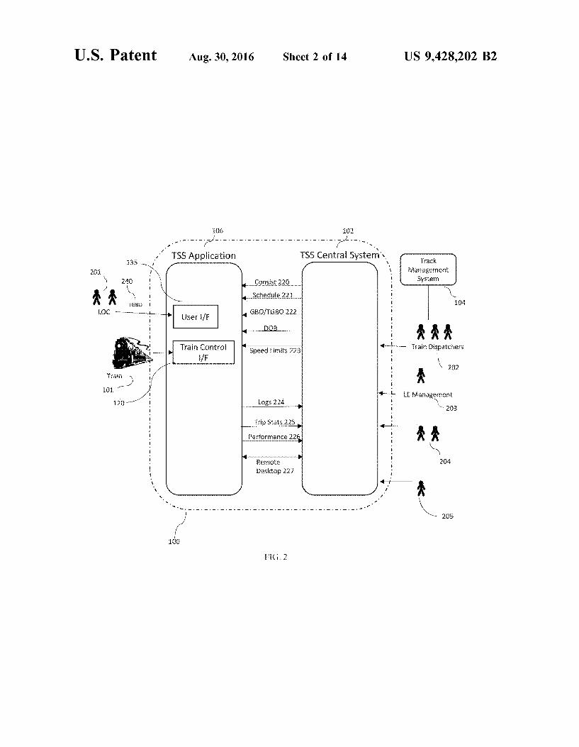
TSS are the GBOs and TGBOS provided by train dispatch ers. The TSS central system receives XML documents from the train dispatchers, parses the contents, stores the infor mation in the database, and provides the information to the pertinent TSS Application devices. The train dispatchers 40 also provide operating timetables which provide information on permanent speed restrictions and what radio frequencies should be used for a given track segment. As per FIG. 2, users of the system may comprise: Locomotive Operating crew (LOC) 201 45 Dispatchers and train operations teams 202 LOC Management 203 and train operators' Safety and
Security teams 204 Administrators to update system information (rail data
base, operating rules, etc.) 205 50 The TSS 100 is connected to the train dispatcher back-end
system 104 using machine-to-machine communication to extract real-time train route, crossover, Switch position, and other information that further enhances the ability to predict, avert, and detect human procedural errors and increase 55 interactivity response validation.
Before the crew is on duty, the GBOs are pushed to an on-board computer running the TSS Application 106a . . . 106m. This punctual information is added to that already included in the base map. The train consist information 60 (locomotives and cars numbers, length, type and weight) is pushed to the system allowing it to calculate, for example, braking curves. When the crew 130 reports for duty they get a copy of a
TGBO 240 for their train, perform their briefing and all other 65 preparatory duties as they do today. Then they go to the train, and perform all the required tests and inspections as today.
4 The TSS Application 106 is similar to a GPS device for
automobiles that displays a map with the location of the train relative to pertinent signals, crossings, etc., and provides guidance to the LOC 130. The TSS Application provides a GUI 135 that informs LOCs of applicable speed limits, radio frequencies for communications with train dispatchers, information from published timetables, and other pertinent operating information. It also provides the option to display an animated map displaying the position of the train relative to upcoming Switches, signals, crossings, hot box detectors, dragging equipment and any other pertinent waypoint or control point information using both text and graphics. The application 106 also provides audible cues to ensure the LOC is alerted to essential information, such as a change in the speed limit. LOCs also have the ability to interact with the application 106 using an optional touch screen, and the application 106 is capable of recording audio responses from the LOC, minimizing or avoiding the need for the LOC to type information or to write notes, as is currently done. The TSS Application 106 provides timely information and
alerts to the LOC to raise awareness of approaching signals, speed limit changes, waypoints/control points, etc. This information facilitates the work of the LOC, enabling them to focus their attention on appropriate locomotive opera tions. As per FIG. 2, information is fed to the TSS from different
Sources, comprising: 1) train dispatchers 202 2) operating timetable (paper-based)
i) Provides information regarding radio frequencies to be used within specific subdivisions
ii) Entered into TSS manually iii) Need to track all changes made.
3) TGBOs and GBOs (sent per train) 222 i) Provided as a direct information feed from source
train dispatcher systems 4) Train Schedule 221
i) Train it ii) Origin, Destination iii) Scheduled departure time
5) Locomotive and consist assignments 222 i) Provides locomotive ID and train cars are assigned to
each scheduled train (train number). Includes spe cific equipment type information.
6) Web Service provides arrival time information to the TSS Application to pass on to the LOC.
FIG. 3 shows the TSS Application computer deployed within the locomotive, with interfaces to GPS and specific locomotive control systems. The diagram also highlights the TSS central server, which receives information from numer ous sources, including train dispatcher systems and TSS Application operational systems such as Operations Data base System (ODBS) and possible Train Schedule Informa tion (TSI) and Business Intelligence (BI) systems. Databases detailing map components of all the pertinent train track locations 105 where the TSS Application operates are stored and maintained up to date within the TSS central system 102. The information relevant to a particular train is down loaded as the train is preparing to begin its run, and is stored by the TSS application local database. The TSS central system 102 periodically synchronizes applicable updates to the TSS applications. The systems communicate leveraging Internet connectivity over cell and/or satellite channels. The central system 102 communicates with the track manage ment system 104 using a Virtual Private Network (VPN), a private Wide area Network (WAN) connection or a Local Area Network (LAN) connection.

US 9,428,202 B2 5
The train dispatchers provide GBO and TGBO informa tion in the form of an XML file. The TSS central system has the capability to receive the GBO and TGBO messages, parse the XML data to manage within the database, and then synchronize the data with the TSSs. This data includes pertinent train operations information Such as: applicable speed limit; applicable location (mile post), date and time of speed restrictions which are translated into GPS-located critical information; and track maintenance procedures.
Operations timetables provided by train dispatchers are entered into the TSS manually with a database editor. In embodiments, the system is designed to facilitate adding information feeds from train dispatchers throughout the system evolution. ODBS (Operations Database System) stores information
regarding train schedules along with locomotive and consist assignment information. For each train number, a locomo tive and consist are assigned. While the assignments are typically done well in advance, changes can be made last minute due to changes in operational requirements or equip ment maintenance issues. ODBS is the operator's applica tion for managing rolling stock, specifically managing locomotive and consist information for each train. The information in the ODBS required by the TSS includes train schedules with equipment assignments per train, including what locomotives and consist are assigned to each Scheduled train.
The TSS receives the schedule and equipment assignment information from ODBS in a timely manner, updates are received often, for example, every 15 minutes. This assures that last minute changes are effectively captured. ODBS interfaces are typically done using file transfer (FTP) solu tions. This information may be more easily accessible from ODS/BI systems that are currently being implemented. As per FIG. 3, the TSS Application provides bi-direc
tional data communication interfaces for Internet access comprising for example one or more of
1. WiFi interface 2. Cellular data communications interface (Such as 3G or LTE)
3. Satellite data wireless interface The TSS Application uses Internet access to establish
connectivity to the TSS central systems. The failover between network access types is automatic. As there remains a risk of losing connectivity, the TSS
Application design takes into consideration that the com plete functionality be available when network connectivity is interrupted. A local database for operational information management is used. Some facilities, like train and refueling stations or main
tenance centers, are equipped with private WiFi Access Points. This communication path is detected and used when available. All data bulk transfer should take advantage of this connectivity in order to reduce operational costs.
If no communication facilities are available, TSS Appli cation-generated data is then stored on the device to main tain full functionality without connectivity. Sufficient hard drive space for at least one week of data storage is required.
All communication sessions (WiFi, HSPA/LTE or Satel lite) are established with a secure and authenticated process (e.g.: SSL or IPsec VPN). An interface is used between the TSS Application and the
GPS installed in the locomotive. The interface provides the TSS Application with precise location information at a frequency of no less than once per second (1 Hz). The TSS Central System receives information feeds from
each of the train dispatchers managing rail used by the
5
10
15
25
30
35
40
45
50
55
60
65
6 operator. While the primary requirement is to receive GBO and TGBO files from the dispatcher systems, development requires two-way messaging between TSS and the train dispatchers. The TSS central system also interfaces with specific operations systems, including ODBS and a TSI.
In some embodiments, the GUI 135 of the TSS Applica tion 106 comprises:
Login page 400 (FIG. 4): a. System status (users logged in, system availability, back office connectivity, updates pending)
b. Basic train and operating information on the login screen (date/time, time Zone, train equipment type, train locomotive ID, locomotive type, train consist, Subdivision name, radio channels)
TGBO conformity screen 500 (FIG. 5): a. TGBO header b. GBO numbers c. Check boxes next to each GBO number (LOC input)
Main operating screen (FIGS. 6A and 6B)—see below. Manual restriction input screen 700 (FIG. 7)
a. TSS Application warns crew on the approach of these points
b. Orange and red buttons generate a reminder on the screen with an audible warning or alarm
c. Yellow with speed values select a speed change on the speedometer and activate the speed logic of the speedometer
d. The screen colors/brightness can be toggled between day and night settings.
To operate across multiple railways, the TSS 100 uses a detailed base map of the routes, a sufficiently precise geo positioning of all the elements that affect the movement of trains, all the applicable GBOs, a set of predefined alerts (visual and audible) and finally an enhanced speedometer display. Thus there is no need for additional capability to be deployed on the physical train track system. The GBOs are pushed to the on board computer, the
timely information is added to the elements already included in the base map. The train consist information (locomotives and cars numbers, length, type and weight) is pushed to the system. As per FIG. 4, the login screen 400 allows the LOC 130
to log in with a user name and password. A verification of the actual (paper version) consist information versus the information present in the TSS Application is necessary in order to ensure that the various vectors are accurate. As TGBO information is vital to the safe operation of the
train, the LOCs validate that the TGBO information loaded and presented by the system is consistent with the TGBO paper copies produced for the LOCs following the current process. As per FIG. 5, using the TGBO conformity screen 500, the LOCs 130 also compare the paper copy of the TGBO with the version contained in TSS Application. A text box showing the last update date and time for the TGBO is included to the TGBO conformity screen. When the TGBO information is not 100% complete and accurate, the LOCs do not use the system during the trip. In some cases of a TGBO inconsistency, it may be possible for TSS to request a correction so that TSS may be used during the trip. Once the TGBO conformity verification is complete, the
primary system display is visible. Optionally, the map animation option may not be available when in the vicinity of major train stations, due to the complexity of managing a large number of diverse tracks.
FIG. 6A shows an example of a main trip operation screen. FIG. 6B shows an example of the main trip operation

US 9,428,202 B2 7
screen with a rolling map 613. The following information is an example of what can be provided on the trip operation SCC.
1. Speedometer 601 a. The needle 602 points to the current speed (in MPH or KM/h) of the train in an analog fashion. The needle may optionally be colored. i. If the maximum allowable speed is exceeded by a
pre-determined margin (e.g. 1-4 MPH), the needle may change color (e.g., orange) and an audible alert is initiated.
ii. If the maximum allowable speed is exceeded by a pre-determined minimum (e.g. 5 MPH or more), a loud audible alarm is initiated, and the needle may turn red. 1. Optionally exceeding the allowable speed by more
than a pre-determined margin (e.g. 5 MPH) trig gers penalty brakes.
b. The numerical reading in the centre 603 displays the current speed (in MPH)
c. The green bar 604 around the outside of the speed dial displays the current permissible speed (in MPH)
d. The yellow bar 605 around the outside or inside of the speed dial shows the next permissible speed (in MPH)
e. The Next Speed text in yellow 606 below the speed ometer displays the next permissible speed numeri cally.
2. Distance Bar 607 a. Displays the distance to the location/milepost where the
speed limit changes. The Solid bar gets Smaller (de scending) as the train approaches the location.
. Penalty Brake Indicator 675 . Display when the penalty brake has been applied . System State Indicator 655 . Indicator shows whether the system is fully operational or is limited in some way.
. Present Time 609 and Time Zone . Displays time and applicable time Zone information. . Departure Time 610 . Displays scheduled departure time from the next sta tion.
7. Control Buttons a. Miscellaneous control buttons allowing users to:
i. Switch screens ii. active/deactivate options (e.g. map, day/night Screen
mode, automated whistle mode, etc.) 8. GBO List 608, 608a a. A scrolling list of GBOS updated as the train progresses
So the information is presented when needed. b. Font is appropriate color and may flash as required
based on visual alert setting. 9. When Approaching Working Party Authority Limits
(Planned Protection Rule) a. Appears in the scrolling list of TGBO entries. b. Provides buttons enabling LOCs to enter required
actions (STOP 652, PROTECT 651, CLEAR 650). Each of a two-man crew must enter the same selection.
c. Details for LOCs and TSS with respect to working party authority limits are as follows: i. Before passing yellow over red signal flags, permis
sion must be obtained from the foreman named in the GBO. If permission is received to pass with no restriction, the CLEAR button is pressed by the LOC, the highlighting on GBO text is removed, and the train is then operated at the normal speed per missible for that section of the track.
:
10
15
25
30
35
40
45
50
55
60
65
8 ii. If permission from the foreman named in the GBO
contains restrictions, the yellow button is pressed by the LOC, TSS lets the train operate manually so the LOC can move according to restrictions, and the GBO visual alerting continues until the train has cleared the limits of the working party authority.
iii. If permission has not been obtained from the foreman named in GBO then red button (STOP) is pressed by the LOC. The TSS requires that the train be brought to a stop before the red signal flags. 1. If the deceleration rate of the train is too slow as
estimated by the braking calculator, an audible alarm Sounds for a pre-determined number of seconds (typically 7 seconds),
2. If by then the deceleration rate is still too slow, a louder audible alarm Sounds; a. Optionally, this may trigger an application of
penalty brakes and disables power control. iv. If conditions change, the system can be reset to
another of the three options if the LOC press match ing buttons.
10. Control Method Changes 611 a. The OCS or CTC or interlocking icon displays when
arriving within a predetermined number of miles of a territory limit (typically 2.25 miles) where the control method changes. i. LOCs are required to acknowledge the change by
pressing the CLEAR button to the right side of the speedometer 1. Failure to acknowledge triggers a visual and
continuous audible alarm. 2. After a certain number of seconds following the
audible alarm, penalty brakes are applied and power control disabled.
As the train proceeds, the TSS shows the train progression on the optional rolling map 613. The map is visible on one or more screens at the option of each user, e.g., users may find it helpful in cases where visibility is reduced by fog, snow or other conditions. When the train approaches a block signal 660, the LOC interprets the signal and presses on the speed 670a . . . 670f associated with the signal. The train braking system can adjust the braking curve accordingly. The application is aware of the location of block signals and it can detect if the LOC has not pressed a speed when approaching a signal. An alarm can be triggered to indicate to the LOC that a block signal needs to be interpreted.
Optionally, a rolling map like that shown on the right side of FIG. 6B may be displayed. The map may include:
1. A simple track diagram representing main tracks with a 4-to-5 mile look-ahead
2. Name of subdivision 3. Cardinals points (map orientation), with direction based
on operating timetable 4. Train direction (arrow on train with point at front-end
location) 5. Mile posts 6. Switches connected to the main tracks 7. Signals 8. Station names 9. Equipment integrity detectors of all kinds, including
hot box, dragging equipment, wheel impact, high water and other types of detectors
10. Railway crossings at grade (diamond) 11. Highway crossing at grade (road crossing) 12. Bridges, overpasses, tunnels, etc. 13. Adjacent railways as per operating timetable 14. Regular station stops for this train

US 9,428,202 B2 9
15. Conditional station stops for this train 16. Whistle posts where whistling is applicable 17. Train front end location (digital display to nearest
tenth of mile) 18. Train rear end location (graphical) 19. Change in method of control (OCS vs. CTC vs.
interlocking) 20. Location of yellow over red flag indicating advance
warning for area of authority for working party. 21. Location of red flag indicating beginning of area of
authority for working party. 22. Location of green flag, indicating beginning of slow
order protection. 23. Location of yellow flag, indicating end of slow order
protection. 24. In OCS territory, facing point switches to be
approached at 50 mph maximum until confirmed to be properly lined for the movement.
The onboard TSS Application provides audio alerts in addition to the visual display alerts for some specific upcom ing restrictions, locations, or conditions. Auditory alerts and alarms are digital audio files played on a speaker at a volume loud enough to alert the engineer of upcoming warnings. For alarms, the Sound is played until the condition returns to normal. For notification, the Sound is played once to direct the crew's attention to the screen for new information.
During regular train operations, LOCs 130 receives GBOs or other restrictions (as by a foreman named in a Planned Protection Rule) by radio. These restrictions are entered into the manual restriction input screen shown as example in FIG. 7. The manual restriction input screen 700 allows the LOC
130 to enter pertinent restriction information (received, say, over a radio call from the dispatcher) into the TSS Appli cation. The TSS is then able to provide the appropriate instructions to the LOCs at the appropriate time, based on the information entered. The screen is designed to facilitate quick and easy entry of typical information and restrictions provided by radio during operation. When approaching the applicable restriction location: a. The manual restriction input screen 700 shows the GBO
information at the bottom of the screen, with visual alert (flashing, colored text) as determined by the alert Settings.
b. Red button restrictions—a STOP entry—activates the braking calculator and an audible alarm
c. Orange button restrictions generate an audible notifi cation.
d. Yellow button restrictions show the speed change on the speedometer at the indicated location and activate the braking calculator.
Once the final destination has been reached, the trip operation mode of the TSS ends and the trip close screen displays. A Summary of the trip is provided, comprising one or
more of the following: a. On-time performance information b. The names of the LOCs active upon arrival c. A list of warnings and errors generated during the trip. The TSS application then uploads the trip logs to the TSS
central system, enabling analysis and replay of the trip. The user interface can be a touch screen mounted at each
crew work position in the locomotive cab. The user interface also generates audio audible to LOCs within the locomotive cabin while the engine is operating. Audio alerts are also generated and are audible to the LOCs. Other input devices
10
15
25
30
35
40
45
50
55
60
65
10 may be required or available, such as a keyboard, pointing device (mouse/trackball), based on the detailed design. The user interface 135 may further comprise: 1. Any upcoming lower speed maximum (for example, permanent speed restriction, temporary speed restric tion, or lower Zone speed) is shown two miles before the location of change by a yellow curved line on the inside of the speedometer scale; a notification Sound is played. a. The distance (numerical) to the point of the speed
restriction is shown. Starting at a minimum distance (e.g. two miles), the distance to the upcoming restric tion is represented on an animated vertical bar graph, with a predetermined resolution, e.g. /10 mile.
b. At the location of restriction, the green line on the speedometer is changed to show the new speed limit. At the same time, the next upcoming maximum speed is then shown by the yellow line. (When the next speed maximum is higher, the yellow line it may be decided to remove the yellow line.)
c. When the speed limit is decreasing from the current limit, the new speed applies as the front end of the train passes the location, but where the speed limit is increasing, the new speed applies when the tail end of the train passes the point of the change. If it is decided that the yellow line is displayed for all speed limit changes, the TSS takes into account the length of the train (computed from the consist information) in determining the point at which the new speed limit is presented. A new higher speed maximum is dis played in green only when the rear end of the train has passed the location of speed change.
2. Signals: a. The distance (numerical) to the next signal is shown.
Starting at a minimum distance (e.g. two miles), the distance to the upcoming signal is represented on an animated vertical bar graph, with a predetermined resolution e.g. /10 mile.
b. An audible notification may be sounded at a pre determined distance (e.g., 4 mile) before the signal (this distance may be speed-dependent) and at the signal.
3. Detector notification: At a pre-determined distance before and after any type of detector present on the main track occupied by the train, a flashing detector icon appears on the TSS screen. The distance may depend on the type of detector.
4. Changing railway method of control: a. At a pre-determined distance before the territory limit
separating different methods of control (e.g. 2/4 miles), a visual prompt appears showing the appro priate icon for the upcoming method of control: Occupation Control System (OCS) or Centralized Traffic Control (CTC) or interlocking. An audible notification may be sounded.
5. Braking curves define the fastest speed the train can be moving at each point and still be able to comply with the new maximum speed requirement at the upcoming restriction location OR, where a stop is required, the fastest speed the train can be moving at each point and still stop with sufficient margin at the location defined by the stop restriction, given the train consist. Speed is monitored by the braking calculator, If the deceleration rate is slower than what is required
as calculated by the braking curve, an audible alarm Sounds,

US 9,428,202 B2 11 12
Following that, if the deceleration rate is still too slow, 1. the default STOP at the location of the current a continuous louder audible alarm Sounds. The alarm signal is cancelled is reset if/when the speed is reduced below the 2. the current speed limit remains as it is, (or is braking curve contour or the train stops. changed to a new value as required by the next
. Since some speed limit information is conveyed by the 5 PSO, GBO, etc.), and signals, TSS gets this information from crew input. An 3. the speed limit beginning at the location of the array of six buttons corresponding to the speeds asso- following signal is set to the value selected. ciated with signal indications is shown on the touch- d. If the speed selections entered by the crew do not screen (or other input device) to be used as described match, TSS immediately sounds an alarm. The crew below. 10 has an interval of time (for example, seven seconds) a. When approaching a signal, the default speed limit or until the train reaches the location of the current
setting (that is, before any entry has been made by signal, whichever is longer, to enter or re-enter their the crew) at the location of the current signal shall be speed selections. Failure to enter matching speeds STOP 15 before passing the signal results in an immediate
b. If the train passes the current signal location without loud continuous audible alarm in the cab. If the speed the crew making any entry, a continuous alarm conveyed by the signal is not input within the Sounds. specified interval, a penalty brake is applied to stop To stop the alarm, the LOC does the following within the train.
a pre-determined interval (e.g., seven seconds): 20 f. Generally, as per normal operating rules, if the signal i. Enter speed conveyed by the signal, if known is no longer visible, the LOC must slow the train to
and agreed to by all members of the crew 15 mph. If the signal indication cannot be remem present in the cabin when signal was passed. bered by all members of the crew present in the cab
ii. Otherwise, if signal indication cannot be in when the signal was passed, the LOC must select remembered and agreed to by all members of 25 the 15-mph speed. In this case, the braking calculator the crew present in the cabin when signal was considers the following signal as a restricting signal. passed, Therefore, as the train passes the signal location: 1. The 15-mph button is selected by the LOC. i. If at least one selection has been entered, but The braking calculator considers the next signal matching entries have not been received, then if it as a restricting signal. 30 is not already active, the 15-mph button is acti 2. The train immediately slows to restricted vated as an option. speed and approaches the next signal prepared ii. If matching entries are received within the remain to stop. der of the interval, the TSS continues as if these
iii. Optionally, if the speed conveyed by the signal were received before the signal location was OR the 15-mph selection is not input within the 35 passed, except: specified interval, a penalty brake is applied to iii. If matching 15-mph entries are made, the speed stop the train. limit at the current location is changed to 15 mph,
c. The crew continues to follow Railway Operating and a text message is added to the top of the GBO Rules regarding siting and interpretation of signals display indicating that the train immediately (for example, calling the signal to each other). In 40 reduces to RESTRICTED speed and approach the addition, the TSS requires that they independently next signal prepared to stop. The text message is interpret the signal to determine the max permissible presented with a visual alert, Such as yellow or speed at the following signal as announced by the flashing text. present signal, and input that speed (CLEAR, 45, 30, g. If a crew member changes his/her entry, the TSS 25, 15, STOP, or some subset of these) by pressing 45 updates the response and revises contingencies con the correct button on the button array. Therefore, sistent with the new speed selection. (This allows a i. At a pre-determined distance before each signal, a crew member to correct an entry that was entered
set of speed options is presented, one button incorrectly as well as allowing entries to be changed associated with each speed. Buttons are visibly in the event that the current signal changes to express activated to show which speeds are possible 50 a different speed after a first entry has been made.) choices for that signal (to a maximum of six). The h. A special timing function often minutes or more as track database provides the set of possible speeds determined allows TSS Application to operate with a that can be indicated by each signal (for example, single signal speed input if one of the crew is out of a signal at a 45-mph crossover can show CLEAR the cabin or otherwise unable to enter a response to crossover set to straight ahead or 45 mph cross- 55 the signal. over set to change tracks). The option buttons for 7. Option to blow whistle at crossing all six speeds are present, and the individual If desired, the LOC may select an option so that the speeds in the button array are in the same loca- TSS Application blows the whistle at crossings tions, but only the buttons for speeds possible for where this is required. The whistle automatically this signal are activated. 60 blows the cadence associated with a train approach
ii. Each member of the crew presses the button ing a crossing from the position of the whistle post corresponding to the speed limit at the following until the train fully occupies the crossing. The posi signal as announced by the current signal as tions of whistle posts and crossings, along with any perceived. special instructions regarding whistling at each
iii. If the speed selections are entered by the LOC 65 crossing, are obtained from the track database. before the signal location is passed, and these Enabling the whistle automation function does not values are found to match, then: disable the manual control.
US 9,428,202 B2 13
The consist information for the train details the number and type of cars comprising the train. The consist informa tion is used to calculate the length of the train to determine when the tail end passes certain locations, to allow for the LOCs to confirm the clearance of equipment beyond certain locations of track (fouling points) to assure safety, in the calculation of braking curves, and optionally, when possible, to indicate the length of the train in the animation.
The LOC is alerted to specific events or issues in a timely fashion. The TSS application therefore is able to generate alerts and communicate those alerts to the LOC in an appropriate fashion based on the severity and importance of the event that generated the alert.
Audio alerts generated for the LOC take into consider ation the noise level and noise spectrum of the locomotive, assuring that the audio alarm is clearly audible and identi fiable by the LOC while the train is operating.
Optionally, the system may provide audio playback capa bility. This is achieved by providing a new audio playback system or through interface to the existing audio playback system in the locomotive cab. In either case, the system needs to meet the requirements below.
Visual alerts are also used, and are integrated into the end-user interface design to assure LOCs are effectively alerted consistent with the severity and importance of the event that generated the alert.
Application of the brakes in circumstances where the train is being operated outside of procedural limits is called penalty braking. In pre-determined situations, the TSS ini tiates the emergency brakes on the train and brings the train to a stop. The TSS has an interface to the locomotives braking controls to provide the capability to trigger the brake systems. As an option, the TSS may also activate the train whistle
when it arrives at designated whistle posts. The interface allows the system to activate the whistle appropriately the cadence of the whistle sound is specifically set for different points on the track. TSS operation has been described in the form of high
level flowcharts showing the process followed for system startup in FIG. 8, operational mode in FIG. 9, and trip close functional sequences in FIG. 10. Each flowchart is accom panied by a detailed functional description that references specific flowchart objects by number, corresponding to the diagram.
System Initialization Flow Chart Details (FIG. 8) 1-System Start 801 LOC initiates TSS startup 2 Health Check 802 System performs a basic health check, including: POST, hardware, memory, OS, etc. Application components active Database integrity Interface tests (TSS central server, GPS, train control
systems) Log results
3–System Update 803 Check for TSS software updates, including applicable
Sub-systems, from centralized servers Log results 4—Login 804 Positive identification of end-user (FIG. 4) Update Log 5 Load Information 805 Train Services Schedule Tabular General Bulletin Orders (TGBOs), DOBs, etc. Update waypoints DB
10
15
25
30
35
40
45
50
55
60
65
14 Cross-reference train ID to locomotive number. Log information loaded/updated 6- Get Train ID 806 Identify which Train ID applies to trip Based on cross-reference table loaded in previous step. Confirm with end-user Provide option for LOC to manually override 7. Retrieve Trip Info 807 Consist information Number of cars Car Type Timetables 8 Pre-Departure System Check 808 System check to be completed prior to commencing trip
control, to include the following: Information for train loaded and up to date Latest TGBOS received 9. Successful System Check? 809 Analyze whether system check completed Successfully Log results 10 Confirm Information Conformity 810 LOC to compare system information with paper copies to
assure system up-to-date. System to present pertinent information for comparison
on-screen, including navigation functionality to facili tate activity.
Multiple sources of TGBO/DOBs are loaded for a specific trip numerous train dispatcher/operators (RTC Office: Rail traffic controller). This occurs generally when a train goes through multiple jurisdictions.
11 Information Conform? 811 LOC to confirm information conformity Log LOC's results, identifying source of non-conformity 12—Launch Operational Mode 812 System initiates operational mode with operational inter
face Log results 13 Critical Error in System Check 813 Analysis if System Check generated critical error(s) Log results 14 Display Warning & Display Instructions 814 Details of system check error to be presented to end-user Instructions/guidance to be presented to end-user Log information 15—Launch Exception Handling (for Information Non
Conformity) 815 Provide end-user with option to resolve errors with infor
mation updates or other pertinent options Capture user information regarding non-conformity of
information Log results 16 Continue (After Information Non-Conformity Error)
816 Provide end user with option to continue or abort Log results 17 Display Error Information & Display Information
817 Provide end user error information and pertinent instruc
tions 18 Stop 818 Log error information System stopped—not operational FIG. 9 shows the System Operational Mode 1-Start Operational Mode 901 Initiate Operational Mode 2 Get GPS Location 902
US 9,428,202 B2 15
Interface with GPS returns current location coordinates and current travel speed
Log GPS location, speed, time, traini 3- Get Speed Limits 903 Identify current applicable speed limit Retrieve speed limit from PSO (Permanent Speed Order) Identify applicable speed limit changes due to TGBO, GBO, or other notice.
Identify milepost where speed changes Identify next applicable speed limit Retrieve next speed limit from PSO (Permanent Speed
Order) Identify applicable speed limit changes due to TGBO, GBO, or other notice.
4—Calculate Schedule Adherence 904 Calculate Schedule Adherence Delay, ETA 5. Update Display Components 905 Current Speed Regular Speed Limit Applicable Speed Limit Update Track Diagram/Animation Schedule Adherence 6—Compare Waypoints vs Location 906 Event Trigger? If an event is triggered, event information is displayed If no event, loop back to #2 Get GPS Location 7 Display Event Information (Refer to Appendix A for
Detailed List) 907 List all applicable events in sequence Detail required actions for event, if as applicable Play sound for event (if as applicable) Log event 8 Confirm Track 908 When appropriate identify on which track the train is
traveling Use technology solution to identify which track Interactive questions to confirm which track 9 Safety Event? 909 Has a Safety Event been triggered? Log Safety Event 10 Launch Safety Event Processes 910 Based on Safety Event, perform appropriate actions.
Example: Over-speed Safety Event: cut engine power and apply brakes
Log results 11 End of Trip? 911 Evaluate if trip has ended If no, loop back to #2—Get GPS Location 12 Launch Trip Close Mode 912 Operational Mode ends, system launches Trip Close Mode
FIG. 10 shows an example flow chart of the Trip Close Mode
1- Trip Close Mode 1001 Initiate Trip Close Mode 2 LOC Trip Close 1002 Confirm Trip Close Capture Notes 3. Upload Trip Information 1003 Upload trip information and logs to central TSS system 4. Close System 1004 Close all active windows and systems Re-launch Application The TSS leverages a local database to store mapping
component information and pertinent GBO and TGBO
10
15
25
30
35
40
45
50
55
60
65
16 information with corresponding location information. The database, GBOs and TGBOs are updated frequently by the TSS Central System. Log information is also stored locally, and is retrieved by
the TSS Central System on a regular basis (frequency to be determined based on technical capabilities and applicable costs). Logs comprise system health information, update timing, information recording, LOC entries, interfaces/net work errors etc. The TSS central system is an application that receives
information from numerous sources, manages this informa tion, provides information updates to the TSS, as well as providing basic administration, management, and reporting tools. The combined system therefore consists of an appli cation server component, a database component, and a web user interface component. The TSS can show on-time performance information,
based on information from a web service. This service can provide the arrival time and on-time performance informa tion. A list of completed runs is available for replay, indexed by
Train it, Origin, Destination, and Date. Other pertinent information is also made available upon request, including identification of the LOC responsible for the train. This is done through a UI for LE and operations management 203, 204. The TSS application 106 interfaces with one or more of
the following systems: i) TSS Central System 102 ii) Database updates, including:
(a) Mapping components 105 (b) TGBO, GBO 222 (c) Operating timetable information (radio frequencies,
etc.) (d) Authorization information (username?passwords) 401
(e) Train schedule including locomotive and consist assignments 221, 220
iii) Application, System, and OS log information iv) Application updates (to be confirmed) V) Business intelligence related data for information con
Solidation on central system vi) Locomotive GPS System vii) Locomotive control systems
(a) Penalty Braking Systems (b) Whistle
viii) Remote Access (“Remote Desktop' functionality) iX) Audio output for alerts and warnings The TSS receives constant updates from the GPS installed
in the locomotive to get current position and current speed information which is cross-referenced with the GPS-located critical information. Any particular TSS may be viewed from any PC within
the operator's network, with appropriate access controls implemented to assure only authorized users have access. The operator can optionally have the capability to replay
a TSS application experience on any trip made with the TSS installed using the logs generated by the application throughout the application. This replay functionality is Sup ported on standard Windows PCs. The replay provides the complete experience of an LOC on the train, from Trip Initialization to Trip Close. When trains are approaching or departing major stations,
there may be a maze of tracks and Switches. Optionally, the system may not provide guidance in moving through these low speed areas. The TSS Application may optionally only begin to give detailed instructions and to display detailed

US 9,428,202 B2 17
animation of track and infrastructure ahead once the train moves away from the major stations. The LOC is notified when guidance begins.
The TSS application is executed on one computer and one or two touchscreen displays with applicable input devices— one for each of up to two crew members in the locomotive. The computer uses Internet access for certain functions, though TSS Application remains fully operational should network connectivity be temporarily unavailable. Local con nectivity is established between the device and train control systems and the locomotive GPS. In the event that the TSS loses network connectivity, the TSS continues to provide full functionality during trips based on its local store of down loaded data. The system provides automated warnings and reminders
by means of rule base alerting strategy by extracting and combining pertinent information while minimizing the LOC's cognitive mental workload. The TSS can monitor the interactivity of the LOC with the
system to detect possible lack of awareness and ensure the LOC respond accordingly. The touch screen capability can help detect mental awareness issues such as, finger tremors indicating tension or fatigue. Sampling of reaction time, attentional focus, and other indicators of awareness, mental sharpness, and fatigue can optionally be performed during off-peak times to ensure the LOCs are maintaining accept able mental awareness. The TSS can be used for continuous improvement of LOC
training by collecting trip reports, logs of conformance to regulations which can later be reviewed and discussed with the LOC.
The TSS can be used in a network of trains all using TSS by means of informing adjacent train proximity to confirm their right of ways.
The TSS capabilities can be adapted to allow use of a single driver in the cabin as opposed to a two-person LOC.
Communication between the train dispatchers and the operator make use of existing, secure connections when available, or connectivity solutions can be developed with each dispatcher. Options include establishing a VPN con nection over the Internet or implementing a direct network link such as an MPLS network connection. Connectivity decisions are made in conjunction with the each individual partner.
Accuracy and precision regarding locations and distance calculations is a prime requirement for the Train Safety Systems. The GPS to be used by the TSS therefore provide specified levels of accuracy and precision and the TSS Software compensates for the margin of error provided by the GPS in order to assure the safety of the passengers, cargo, crew, and equipment, as well as the safety of any other organizations and the general public. The TSS can also calculate the length of the train for
safety reasons as it influences the speed allowed at critical locations. As the length is a function of the number of cars, type of cars (provides length), locomotive type (provides length), and GPS placement, the system compensates for inaccuracies to assure safety. GPS placement on the loco motive is not always consistent. Other GPS-based electronic devices, such as end-of-train can also be used to increase the accuracy and reliability of the estimations. When the system is confirming that the train has cleared a fouling point, a margin for error is included in the calculation to assure safety. The TSS applies human factors to define an IT-based
process to reduce the mental workload (cognitive and memory demands) on the locomotive crew. It provides a
10
15
25
30
35
40
45
50
55
60
65
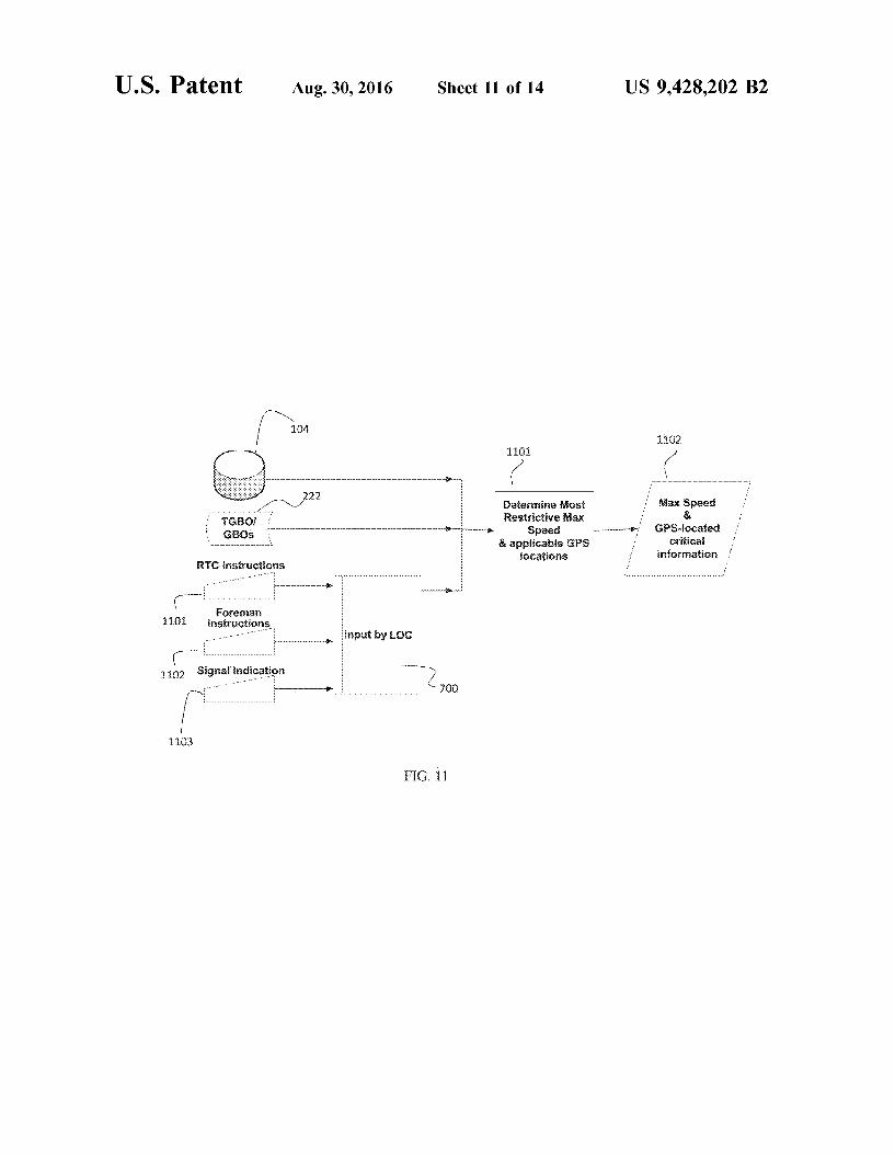
18 method of extracting and combining information from per manent slow orders, temporary slow orders, real-time signal recognition 1103, and instructions conveyed to the crew 700 through the various GBOS 222, foreman's 1102, and dis patcher's 1101 instructions, to identify the speed limit at each point along the route. As per FIG. 11, the TSS may further comprise:
i) Processes 1103 to parse GBO 222 information to extract the instruction type and the milepost where the instruc tion applies.
ii) GPS coordinates for the visible signals used to control train traffic on the railway (e.g. block signals, panel signals, flags) are obtained and included in the track database 105 to ensure that the location information for speed limit changes is precise. 1104
iii) GPS-located critical information is prioritized based for example on restriction or distance to determine the best order to present information to the crew.
iv) Calculation of speed limit based on the GPS-located critical information to compare with real time moni toring of speed (obtained from either GPS or conven tional measurement technology, e.g. the conventional locomotive speedometer) to detect over-speeding and application of brakes to maintain acceptable speed at all times 1102.
V) Logic process (as per FIG. 12, 13) to present speed and other information (location of signals, upcoming rail road and highway crossings, location of Switches, Sid ings, etc.) in the most appropriate order and at the most appropriate time, in an attempt to prevent errors from memory lapse, distraction, competing stimuli, or inat tention.
vi) Use of GPS-determined speed for on-going calibration of conventional speed determination, which is useful to ensure the greatest possible range for dead reckoning of position, needed to allow the TSS to continue to operate when the GPS becomes unavailable for any reason.
FIG. 12 shows an example of the process used to display the information on the application. When the trip begins, the list of GPS-located critical information 1201 is loaded and sorted. The maximum speed for the first speed Zone is determined 1202 and displayed on the application 1205. If the end of the trip is not reached 1206, when the train has gone by the first speed Zone 1207 the following speed Zone is displayed. In this example the LOC can see two speed Zones ahead, but the system could be configured to show any number of upcoming Zones.
FIG. 13 shows a process wherein the system looks ahead to ensure there is sufficient braking time to meet future speed Zones. The current speed 1301 is used to calculate the look-ahead which is a factor (e.g. 2) times the stopping distance 1302 for the current speed. All speed Zones con tained within the look-ahead distance 1303 are identified. If there is more than one speed Zone in the look-ahead window 1304, and the second next speed limit is lower than the immediately next speed limit, the braking curve for con forming to the second next speed limit from the current speed is calculated 1305, taking into account all relevant information about the train consist, etc. If the braking curve shows that the speed required to maintain safe operation of the train across the boundary of the second next speed Zone would require a slower speed at the location of the start of the immediately next speed Zone, then the speed Zones are deemed to be too close together and the speed limit for the immediately next speed Zone is set to the speed determined for that location by the computed braking curve 1310, and that adjusted value is displayed on the application.

US 9,428,202 B2 19
FIG. 14 shows an example of a look-ahead window 1401 that has found speed limits that are too close together. The look-ahead is based on a window twice the stopping distance of the starting 100 mph speed of the train. Speed Zones A 1402, B 1403 and C 1404 are displayed along with their corresponding speed limits 1405, 1406, 1407. The braking profile is calculated 1408, and the lower speed of the braking profile and the limit is used for the speed Zone B 1409: the speed Zone limit 1406 is 60 km/h but the braking profile 1408 requires the train to be at a speed no greater than 50 km/h 1409 at that same location in order to comply with the next speed limit 1407 at speed Zone C.
Although the algorithms described above including those with reference to the foregoing flow charts have been described separately, it should be understood that any two or more of the algorithms disclosed herein can be combined in any combination. Any of the methods, algorithms, imple mentations, or procedures described herein can include machine-readable instructions for execution by: (a) a pro cessor, (b) a controller, and/or (c) any other Suitable pro cessing device. Any algorithm, Software, or method dis closed herein can be embodied in software stored on a non-transitory tangible medium such as, for example, a flash memory, a CD-ROM, a floppy disk, a hard drive, a digital versatile disk (DVD), or other memory devices, but persons of ordinary skill in the art will readily appreciate that the entire algorithm and/or parts thereof could alternatively be executed by a device other than a controller and/or embod ied in firmware or dedicated hardware in a well known manner (e.g., it may be implemented by an application specific integrated circuit (ASIC), a programmable logic device (PLD), a field programmable logic device (FPLD), discrete logic, etc.). Also, some or all of the machine readable instructions represented in any flowchart depicted herein can be implemented manually as opposed to auto matically by a controller, processor, or similar computing device or machine. Further, although specific algorithms are described with reference to flowcharts depicted herein, per sons of ordinary skill in the art will readily appreciate that many other methods of implementing the example machine readable instructions may alternatively be used. For example, the order of execution of the blocks may be changed, and/or some of the blocks described may be changed, eliminated, or combined.
It should be noted that the algorithms illustrated and discussed herein as having various modules perform par ticular functions and interact with one another. It should be understood that these modules are merely segregated based on their function for the sake of description and represent computer hardware and/or executable software code which is stored on a computer-readable medium for execution on appropriate computing hardware. The various functions of the different modules and units can be combined or segre gated as hardware and/or Software stored on a non-transitory computer-readable medium as above as modules in any manner, and can be used separately or in combination.
While particular implementations and applications of the present disclosure have been illustrated and described, it is to be understood that the present disclosure is not limited to the precise construction and compositions disclosed herein and that various modifications, changes, and variations can be apparent from the foregoing descriptions without depart ing from the spirit and scope of an invention as defined in the appended claims. The invention claimed is: 1. A safety system for a train having a locomotive
operating crew, said system comprising:
10
15
25
30
35
40
45
50
55
60
65
20 a database containing one or more railroad maps and one
or more train dispatcher information systems; a central server adapted to be at least intermittently
coupled to said database to generate GPS-located criti cal information;
a GPS device on-board the train to monitor the real-time location of the train; and
a computer on-board the train and adapted to be at least intermittently coupled to said central server and said GPS device for executing an application utilizing said GPS-located critical information and said real-time location of the train;
wherein said application generates alerts for said locomotive operating crew
based on the GPS-located critical information and the real time location of the train, so that the crew is alerted as to upcoming changes to be implemented, and
identifies a maximum permissible speed for said train at each point along a predetermined route for the train based at least in part on said GPS-located critical information, and
at least one of said application and said central server is adapted to detect a type of equipment included in a consist, and to generate a maximum permissible speed based on said type of equipment.
2. The safety system of claim 1 which includes one or more network interfaces between said central server and said on-board computer for communications between said on board computer and said central server to maintain the GPS-located critical information up to date.
3. The safety system of claim 1 in which said maximum permissible speed is combined with speed limits entered into said on-board computer by said crew, to establish an allowed speed at a selected GPS location.
4. The safely system of claim 1 in which said on-board computer receives information representing the actual speed of said train, and said application generates an alarm when said actual speed exceeds said maximum permissible speed.
5. The safety system of claim 1 in which said on-board computer generates alarms when a railroad signal is passed without acceptable speed selections being made by said CW.
6. The safety system of claim 1 in which at least one of said application and said central server use dead reckoning to determine the real-time location of said train if said GPS device cannot determine the real-time location of said train.
7. The safety system of claim 1 in which at least one of said application and said central server is adapted to receive manual input of GPS-located critical information.
8. The safety system of claim 1 in which at least one of said application and said central server is adapted to receive input from a train dispatcher while the train is running.
9. The safety system of claim 8 in which said input comprises information sent over a radio or other communi cation means to said crew.
10. A method of assisting the safe operation of a train adapted to be operated by a locomotive operating crew, said method comprising
generating GPS-located critical information at a central location, said GPS-located critical information being based at least in part on one or more railroad maps and one or more train dispatcher information systems;
monitoring a real-time location of the train with a GPS device on-board the train;
generating alerts for said locomotive operating crew based on the GPS-located critical information and the

US 9,428,202 B2 21
real time location of the train, so that the crew is alerted as to upcoming changes to be implemented,
identifying a maximum permissible speed for said train at each point along a predetermined route for the train based at least in part on said GPS-located critical information,
combining said maximum permissible speed with speed limits entered into said on-board computer by said crew, to establish an allowed speed at a selected GPS location, and
at least one of said application and said central server detects a type of equipment included in a consist, and generates a maximum permissible speed based on said type of equipment.
11. The method of claim 10 which includes maintaining the GPS-located critical information up to date with com munications between said on-board computer and said cen tral server to maintain.
12. The method of claim 10 which includes combining said maximum permissible speed with speed limits entered
10
15
22 into said on-board computer by said crew, to establish an allowed speed at a selected GPS location.
13. The method of claim 10 in which said on-board computer receives information representing the actual speed of said train, and said application generates an alarm when said actual speed exceeds said maximum permissible speed.
14. The method of claim 10 in which said on-board computer generates alarms when a railroad signal is passed without acceptable speed selections being made by said CW.
15. The method of claim 10 in which at least one of said application and said central server use dead reckoning to determine the real-time location of said train if said GPS device cannot determine the real-time location of said train.
16. The method of claim 10 in which at least one of said application and said central server receives manual input of GPS-located critical information.
17. The method of claim 10 in which at least one of said application and said central server receives input from a train dispatcher while the train is running.
k k k k k

UNITED STATES PATENT AND TRADEMARK OFFICE
CERTIFICATE OF CORRECTION
PATENT NO. : 9,428,202 B2 Page 1 of 1 APPLICATION NO. : 14/466000 DATED : August 30, 2016 INVENTOR(S) : Claude Perras, Leigh Thorpe and Francois Blouin
It is certified that error appears in the above-identified patent and that said Letters Patent is hereby corrected as shown below:
In the claims,
Column 20, Line 36 (Claim 4, Line 1), delete “The safely system of claim 1 and insert --The safety system of claim 1-- therefor.
Signed and Sealed this Twenty-second Day of November, 2016
74-4-04- 2% 4 Michelle K. Lee
Director of the United States Patent and Trademark Office