1200/1100 series hplc troubleshooting and maintenance · pdf filepump injector . repeatability...
TRANSCRIPT

Agilent Technologies 1200/1100 Series HPLC Troubleshooting and Maintenance Seminar
Patrick Cronan & Sue D’Antonio LC Applications Scientists

Agilent Technologies HPLC Systems
•All stackable modules for small bench space •Single system control
module •Front access for customer
maintenance •Ergonomic tubing
organization for lowest delay volume and bandspreading
•Single CAN cable connection
•All modules have RS 232, HP IB, Start/Stop, CAN
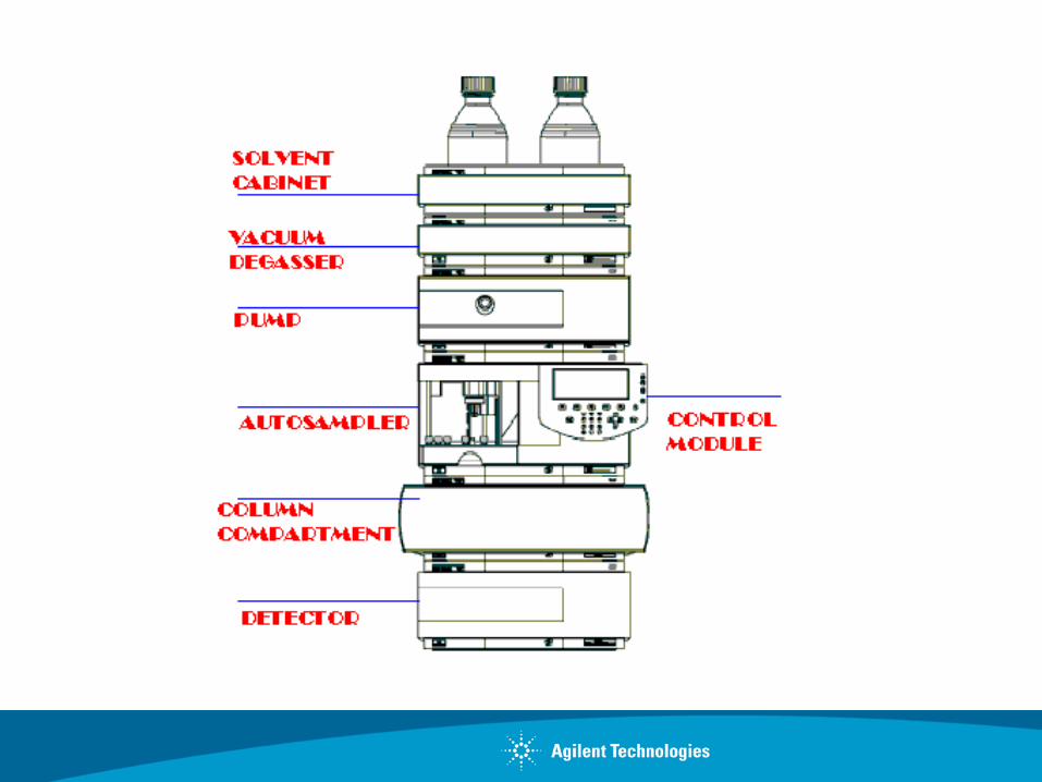

THE STACK Flow connections in the stack: Example setup with 0.17mm ID green capillaries
Solvent bottles - degasser: G1311-60003 (bottle-head assembly, PTFE-tubings)
Pump - autosampler: G1312-67305 (SST, green)
Degasser - pump: G1322-67300 (PTFE-tubings)
Autosampler - column compartment: G1313-87305 (SST, green)
Column compartment - column: G1316-87300 (SST, green)
Column - detector: DAD G1315-87311 (SST, coated) VWD 5062-8522 (PEEK)
Detector - waste: DAD 0890-1713 (PTFE, wide bore) VWD 5062-8535 (PEEK) 5062-2463 (corrugated waste tubing, reorder pack)
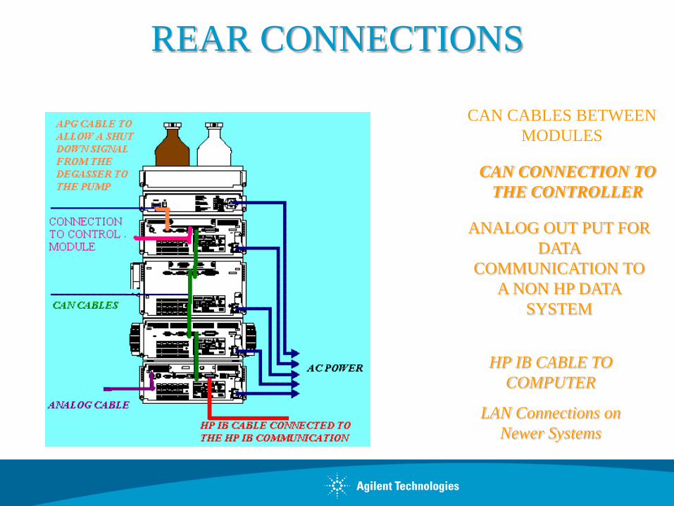
REAR CONNECTIONS
CAN CABLES BETWEEN MODULES
CAN CONNECTION TO THE CONTROLLER
ANALOG OUT PUT FOR DATA
COMMUNICATION TO A NON HP DATA
SYSTEM
HP IB CABLE TO COMPUTER
LAN Connections on Newer Systems

What are Chromatographers Looking for?
Better performance Baseline separation in shortest time Repeatability of results Accuracy of results Sensitive detection Standard, narrow bore and capillary column capability

The Goal of Separation -Resolution Between Sample Components
R - resolution
t - retention time of component B
t - retention time of component A
w - width at base of peak
w - width at half-height
A B
t RA
t RB
0
R=2t - t RB RA W + W A B
R=1.176t - t RB RA W + W 1/2A 1/2B

Det
ecto
r R
espo
nse
Inje
ct
Time
High Efficiency
Low Efficiency
CapacitySelectivityEfficiency
R = 1/4 N x x k'1 + k'
- 1
The Goal of Separation -Resolution Between Sample Components

Performance Characteristics of an HPLC System
Pump
Injector
Repeatability of retention times Delay volume
Repeatability of peak areas Dead volume
Peak elution order
Baseline: noise, drift and wander
Flow: accuracy, precision Composition: accuracy, precision
Injection volume precision Linearity, dynamic range Carry over
Wavelength: accuracy, precision Signal linearity
Spectral resolution (DAD only)
Column temperature accuracy Column temperature precision
Influenced by one module...
Detector
Column compartment
Influenced by several modules...

Instrument Status Indicator The instrument status indicator indicates one of four possible instrument conditions: • When the status indicator is OFF (and power switch light is on), the quaternary pump is in a prerun condition, and is ready to begin an analysis. • A green status indicator, indicates the quaternary pump is performing an analysis (run mode). • A yellow indicator indicates a not-ready condition. The quaternary pump is in a not-ready state when it is waiting for a specific condition to be reached or completed (for example, immediately after changing a setpoint), or while a self-test procedure is running. • An error condition is indicated when the status indicator is red. An error condition indicates the quaternary pump has detected an internal problem which affects correct operation of the quaternary pump. Usually, an error condition requires attention (for example, leak, defective internal components). An error condition always interrupts the analysis.

Solvent Filters
Solvent Inlet Filer
Stainless Steel or glass with 10 micron porosity.
Removes particulates from solvent.
Precolumn Filter
Used between the injector and guard column.
2 to 0.5 micron
Removes particulates from sample and autosampler wear debris.
Must be well designed to prevent dispersion.
11
Guard column
Injector
Analytical Column
Precolumn Filter
Solvent Inlet Filter

Agilent 1200 Series Vacuum Degasser
Recommended for ... • reliable performance with gradient pumps using low pressure mixing • improved performance with all pump designs at low flowrates • use with detectors requiring oxygen-free mobile phase
Features/Benefits • Convenient and cost effective alternative to helium sparging • High degassing efficiency for trouble-free system operation (<1.5 ppm oxygen at 10 ml/min) • Low internal volume (12 ml) for fast solvent changeover • Up to 4 channels for highest versatility • Stackable with other Agilent 1200 Series modules

The Vacuum Degasser

Priming and Purging the System The system can be primed either by drawing solvent
through the degasser with a syringe or by pumping with the pump.
Priming the system with a syringe is recommended, when:
vacuum degasser or connected tubings are used for the first time or vacuum tubes are empty or
changing to solvents that are immiscible with the solvent currently in the vacuum tubes.
Priming the system by using the pump at high flow rate (3–5 ml/min) is recommended, when:
pumping system was turned off for a length of time (for example, overnight) and if volatile solvent mixtures are used, or
solvents have been changed.

Agilent 1200 Series On-line Degasser -Influence on Detector Baseline
no degassing
Abso
rban
ce
helium degassing
Agilent on-line degassing
1 2 3 4 5 6 7 8 9
Time (min)
Solvent: methanol; UVsignal: 210 nm

Agilent 1200 Series On-line Degasser
-Influence on Reproducibility
Lysozyme Analysis
24 25 26 27 28 29
60
50
40
30
20
10
0
mAU First
analysis Last analysis
after 30 hours
24 25 26 27 28 29
60
50
40
30
20
10
0
mAU
Last analysis
after 30 hours
First analysis
Helium Degassing
On-line Vacuum Degassing

Pump
Important characteristics
Common to isocratic and gradient pumps
Flow accuracy
Flow precision
Pressure pulsation
Gradient pumps only Delay volume in low and high pressure mixing Composition accuracy
Composition precision
Influence on...
Retention time and peak area precision (system to system) Retention time and peak area precision (within one system) Baseline noise
Gradient shape and precision
Retention time and peak area precision (system to system) Retention time and peak area precision (within one system)

The Agilent 1260/1200/1100 Series Pumps
Common Features • Complete with solvent bottle, filter, cabinet, purge valve and tubing's for fast start up • Dual-piston, variable stroke volume, and pulse dampener for pulseless flow • Automatic stroke volume adjustment for excellent mixing and noise-free baselines • Improved valves for longer life and lower replacement cost • Optional seal wash for trouble-free operation with high salt mobile phases • Easy to maintain and repair

Operating Principle of the Dual Piston Pump
From solvent bottle
Solvent
High pressure side
1.Piston 2. Piston
Active inlet valve (AIV)
Damper
Pressure measurement
Purge valve
Outlet valve
Seals

Pump - Main Components
Damper Pump head
Leak sensor
LPM board Pump drive
Quaternary Pump Binary Pump
Pump head A
Pump head B
MCGV Solvent selection valve

Isocratic Pump
Damper
(Pressure measurement) Piston head
Working Principle
Piston 1 Piston 2
Maintenance areas:
Seals,
AIV,
Outlet valve,
Purge valve,
Pistons.

Quaternary Pump with Vacuum Degasser
Vacuum degasser
Quaternary Pump
MCGV
Working Principle
Maintenance areas:
Seals,
AIV,
Outlet valve,
Purge valve,
Piston.

Binary Pump
Pumpheads
Solvent Selection Valve (Option)
Working Principle
Maintenance areas:
Seals,
AIV,
Outlet valve,
Purge valve,
Piston.

Pump Models for 1100 & 1200
Isocratic Pump Quaternary Pump Binary Pump

Dwell volume = volume from formation of gradient to the column
Behaves as isocratic hold at the beginning of gradient.
Dwell volume for low pressure mixing system
UHPLC Volume Effects
Dwell volume for high pressure mixing system
beginning beginning
Standard delay mode Low delay mode

Comparison of System Delay Volumes
Pump w/o mixer w/ mixer
Mixer
Autosampler Standard
Bypass
Column compartment standard
Bypass
1090 1050 1200 Quat. 1200 Bin. 300-500 1050-1250 750 V (loop) N/A 4.1 or 8.2 0
180-480 600-900
420
300 + V (inj)
6.2
3 or 6 0
800-1200 n/a
n/a
300 + V (inj)
6.2
3 or 6 0
800-1200 n/a
n/a
327 + V (inj)
8
15 ul 0
min Range Max Range
304-504 1058-1258
189-489 906-1206
1203-1406 1242-1442

System Delay Volume with Low Pressure and High Pressure Gradient Pump
mAU
300
200
100
0
Time [min]
3 4 5 6 7 8 9 10
Solvent A: Water Solvent B: Water+0.5%
Acetone
Flow rate: 1.0 ml/min Pressure: 130 bar
Gradient Start
High pressure gradient pump
without mixer 380 µl
with mixer 850 µl
Low pressure gradient pump 950 µl
Agilent1100 /1200 Pumps
Performance

Solvent Compressibility Corrections
TIME
0
100 One Piston
Cycle
System Pressure=0 System
Pressure>0
Piston Movement (µl)

Column Protection: Soft Start Function
Time (min)
Flow rate (ml/min)
ml/min
Flow Rate Ramp
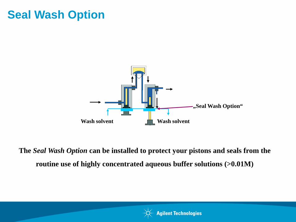
Seal Wash Option
The Seal Wash Option can be installed to protect your pistons and seals from the
routine use of highly concentrated aqueous buffer solutions (>0.01M)
„Seal Wash Option“
Wash solvent Wash solvent
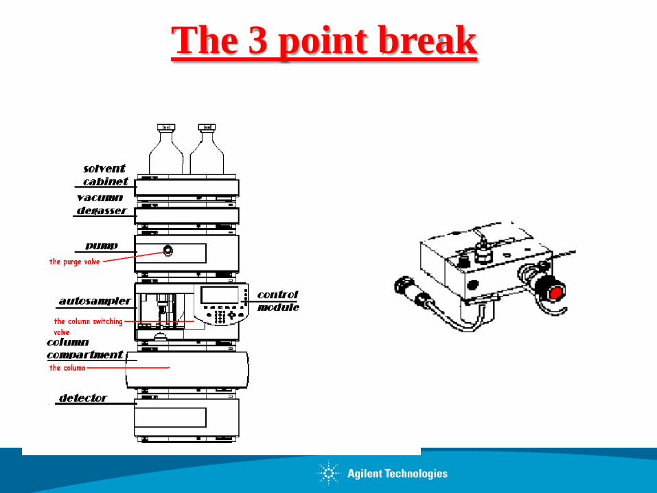
The 3 point break

Purge Valve – Exchanging the PTFE Frit
PTFE- frit
Gold Seal
Plastic cap
1. Unscrew the valve using a 14 mm wrench
2. Remove the plastic cap and the gold seal
3. Take out the frit (tweezers)
4. Install a new frit
5. Replace the gold seal and the plastic cap
6. Install the valve
Note: Realign the waste tube in the correct orientation during installation.


The Outlet Ball Valve

Outlet Valve – Cleaning or Exchanging the Outlet Ball Valve
Valve housing
Gold Seal
Plastic cap
1. Remove the capillary from the valve
2. Remove the valve using a wrench
3. Clean the ball valve in the ultrasonic bath or replace the ball valve
a. Take off the plastic cap and gold seal
b. Replace the ball valve
c. Replace the gold seal and cap
4. Reinstall
Note: The outlet ball valve of the binary pump has an additional sieve (5063-6505)

Active Inlet Valve (AIV) – Old/New
Active Inlet Valve (AIV)
Cartridge 8
New design
1
Old design
1. Remove the AIV using a 14 mm wrench
2. Change the cartridge (new design)
3. Change the gold seals when necessary
4. Reinstall the AIV
Note: Properly position the AIV cable when you reinstall the valve
2

Removing the Pump Head
1. Remove all capillaries 2. Disconnect the AIV supply cable 3. Remove both pump head hexagonal
screws 4. Remove the pump
screw 4mm
screw 4mm

Disassembling the Pump Head
The two parts of the pump head are disconnected by releasing the lock screw.
Video out of the maintenance CD-ROM

Changing the Pump Seals
Video from the maintenance CD-ROM
1. Remove the old seals.
2. Remove the wear retainers, if present.
3. Clean the pump chambers.
4. Insert new seals.
5. Reassemble the pump head.
6. Perform seal wear-in procedure for standard seals
Wear retainer

Changing and Inspecting the Sapphire Pistons
1. Disassemble the pump head assembly
2. Check the plunger surface and remove any deposits or layers with alcohol or tooth paste
3. Replace the pistons if scratched
4. Reassemble the pump head
5. Check to make certain there are not any fractures in the springs
6. Put in the pistons

Agilent 1200 Series Quaternary Pump: Variable Stroke Influence on Composition Ripple
min 60 70 80 90 100 110
mAU
100 µl Stroke
35 µl Stroke
min 112 114 116
mAU
35 µl Stroke
100 µl Stroke
Tracer Water/Methanol +0.5% Acetone Flow rate 1 ml/min Gradient 55-65 %

Agilent 1200 Series Pumps:
Gradient Performance 0-10%B
Tracer Water/Water +0.5% Acetone Flow rate 1 ml/min Gradient 0-10 %
min
mAU
min
mAU
Quaternary Pump Binary Pump
100 µl stroke autostroke

Injector
• Influence on...
• Precision of peak area/height
• Accuracy of peak area/height (when using different injection volumes)
• Precision of peak area/height • Versatility, application range
• Important performance characteristics
• Injection volume precision
• Wide linearity
• Minimum carry over
• Wide dynamic injection volume

The 3 point break

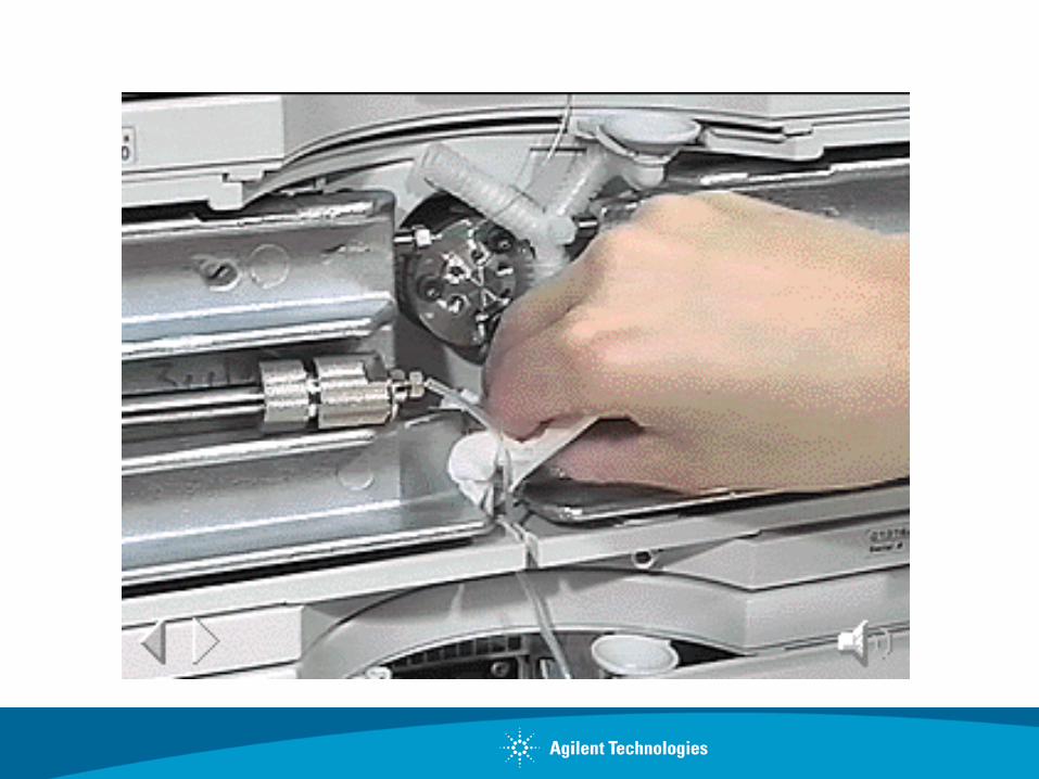
The autosampler connections

The injection sequence


Thermostatted Column Compartment
• Influence on...
• Elution order • Peak identification
• Elution order • Retention time precision • Peak identification
• Important performance characteristics
• Excellent temperature accuracy
• Excellent temperature precision
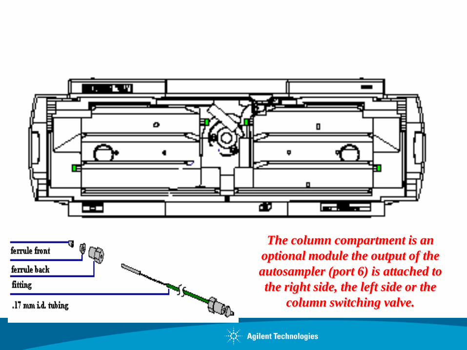
The column compartment is an optional module the output of the autosampler (port 6) is attached to the right side, the left side or the
column switching valve.

1200 Series TCC SL Pre-column Heater and Post-column Cooler
• L-shaped pre-column heater • Volume: 1.6 µl • Mounted on carrier
• U-shaped Post-column cooler • Volume: 1.5 ul • Mounted on Carrier
Holes to attach carrier

Effect of Temperature on Separation
40º C
65º C
100 5
Time in Minutes
A B
AB

Split Peaks
Can be caused by:
• Column contamination
• Partially plugged frit
• Column void
• Injection solvent effects
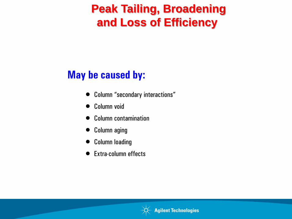
Peak Tailing, Broadening and Loss of Efficiency
May be caused by:
• Column “secondary interactions”
• Column void
• Column contamination
• Column aging
• Column loading
• Extra-column effects
0.0 2.5 5.0
2
41
3
Time (min)
2
41
3
0.0 2.5 5.0Time (min)
2
41
3
0.0 2.5 5.0Time (min)
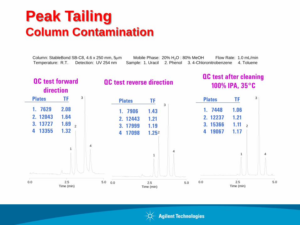
Peak Tailing Column Contamination
Column: StableBond SB-C8, 4.6 x 250 mm, 5µm Mobile Phase: 20% H2O : 80% MeOH Flow Rate: 1.0 mL/min Temperature: R.T. Detection: UV 254 nm Sample: 1. Uracil 2. Phenol 3. 4-Chloronitrobenzene 4. Toluene
Plates TF
1. 7629 2.08 2. 12043 1.64 3. 13727 1.69 4 13355 1.32
Plates TF
1. 7906 1.43 2. 12443 1.21 3. 17999 1.19 4 17098 1.25
Plates TF
1. 7448 1.06 2. 12237 1.21 3. 15366 1.11 4 19067 1.17
QC test forward direction
QC test reverse direction QC test after cleaning
100% IPA, 35°C
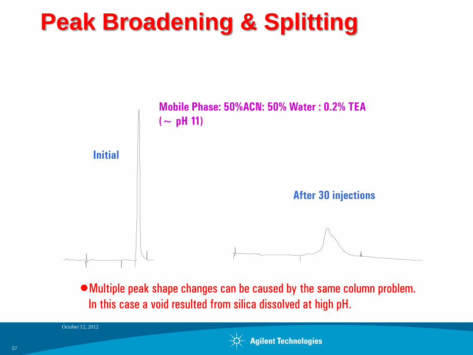
Peak Broadening & Splitting
October 12, 2012
57
•Multiple peak shape changes can be caused by the same column problem. In this case a void resulted from silica dissolved at high pH.
Mobile Phase: 50%ACN: 50% Water : 0.2% TEA (~ pH 11)
After 30 injections
Initial
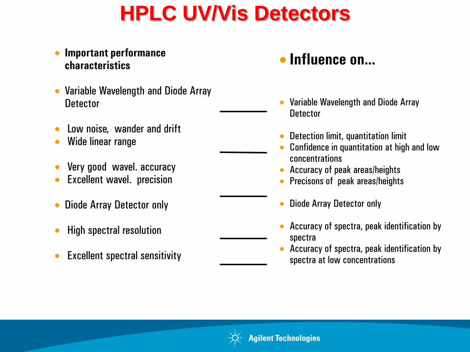
HPLC UV/Vis Detectors
• Influence on...
• Variable Wavelength and Diode Array Detector
• Detection limit, quantitation limit • Confidence in quantitation at high and low
concentrations • Accuracy of peak areas/heights • Precisons of peak areas/heights
• Diode Array Detector only
• Accuracy of spectra, peak identification by
spectra • Accuracy of spectra, peak identification by
spectra at low concentrations
• Important performance characteristics
• Variable Wavelength and Diode Array Detector
• Low noise, wander and drift • Wide linear range
• Very good wavel. accuracy • Excellent wavel. precision
• Diode Array Detector only
• High spectral resolution
• Excellent spectral sensitivity
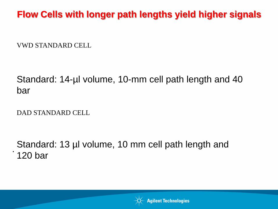
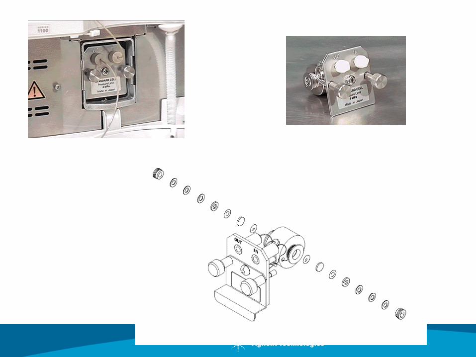
Standard: 13 µl volume, 10 mm cell path length and 120 bar
.
Standard: 14-µl volume, 10-mm cell path length and 40 bar
Flow Cells with longer path lengths yield higher signals
VWD STANDARD CELL
DAD STANDARD CELL
Page 60
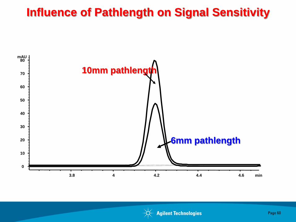
Influence of Pathlength on Signal Sensitivity
min 3.8 4 4.2 4.4 4.6
mAU
0
10
20
30
40
50
60
70
80
10mm pathlength
6mm pathlength

min 0.1 0.2 0.3 0.4 0.5 0
80Hz
PW=0.30sec
40Hz
PW=0.33sec
20Hz
PW=0.42sec
10Hz PW=0.67sec
5Hz PW=1.24sec
• Sample: Phenone Test Mix • Column: Zorbax SB-C18, 4.6x30, 1.8um • Gradient: 50-100% ACN in 0.3min • Flow cell: 5ul
20Hz versus 80Hz + 40% Peak Width – 40% Peak Capacity – 30% Resolution – 70% Apparent Column Efficiency
10Hz versus 80Hz + 120% Peak Width – 120% Peak Capacity – 90% Resolution – 260% Apparent Column Efficiency
Benefit of 80Hz Data Acquisition Rate Peak Width, Resolution and Peak Capacity in Ultra-Fast LC


Changing the VWD Lamp
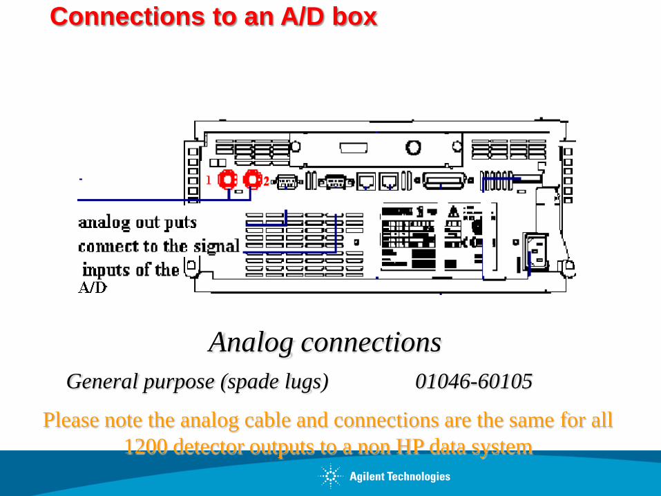
Connections to an A/D box
General purpose (spade lugs) 01046-60105
Analog connections
Please note the analog cable and connections are the same for all 1200 detector outputs to a non HP data system

Wavelength Range: 190 - 950 nm
Lamps: Shine-through deuterium lamp (uv-range) Tungsten lamp (vis-range)
Slits: Programmable electromechanical; 1, 2, 4, 8 and 16 nm
Noise: 2x10⁻⁵ AU at 254 nm and 750 nm
Flow Cells: STD 10 mm 13 ul, Semi-micro 6 mm 5 ul, Micro/HP 10 mm 1.7 ul, 500 nl flow cell
HP 1200 Diode Array
Tungsten Lamp Deuterium Lamp
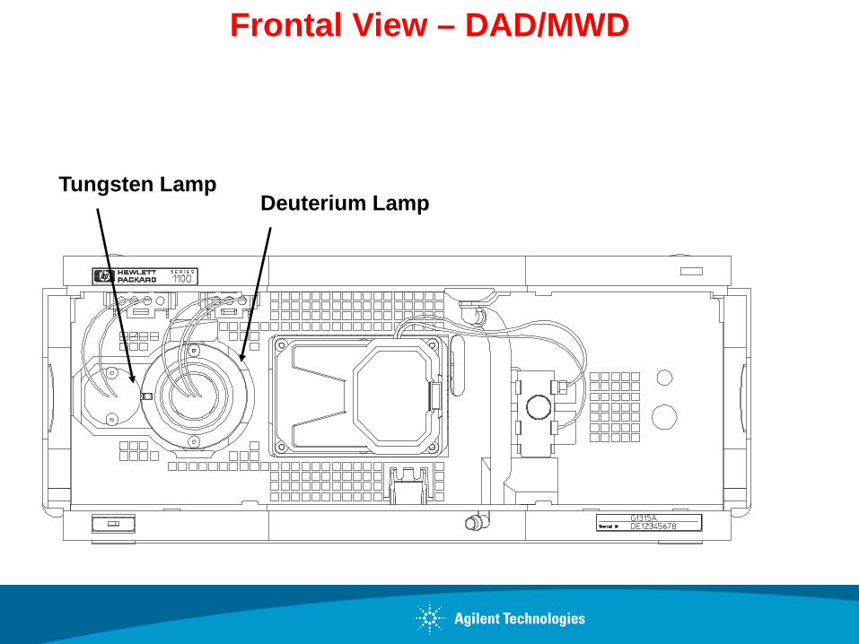
Frontal View – DAD/MWD

Tungsten lamp Coupling lens Deuterium lamp
Source lens (Achromat)
Holmium oxide filter
Support lens
Flow cell
Spectro lens
Grating
Array
Programmable Slit
Optical Path - HP 1200

1260 &1290 Infinity Diode Array Detectors
Deuterium lamp
„Max-Light“ cartridge flow cell with 10 or 60 mm flow cell
Programmable slit
Diode array with 1024 elements
Grating Mirror
Page 69
Optofluidic Waveguides: Max-Light Flow Cells Total-internal reflection in a non-coated fused silica fiber

Diode Array Parameters - Review
Spectral Storage Parameters
Signal Storage
Response Time

signal wavelength
bandwidth 30 nm
reference bandwidth
reference wavelength 350 nm
100 nm
Sample Signal and Reference Optimization
Wavelength (nm)
mA
U

Diode Array: Signal Extraction with Isoplot

Action keys
Direction keys
Alphanumeric keys
Navigation keys Start / Stop keys

Customizable Status Display
Direct parameter change
Signal Plot
Tiles customizable by user
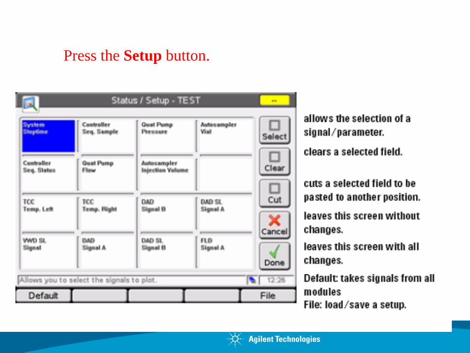
Press the Setup button.

Setup of a Status Information Screen
When the Status Information screen has not been setup before, it will show from each module in the system one or more signals/parameters

Customizable Status Display
Screen customizable
Tile with 4 subtiles
Direct parameter change
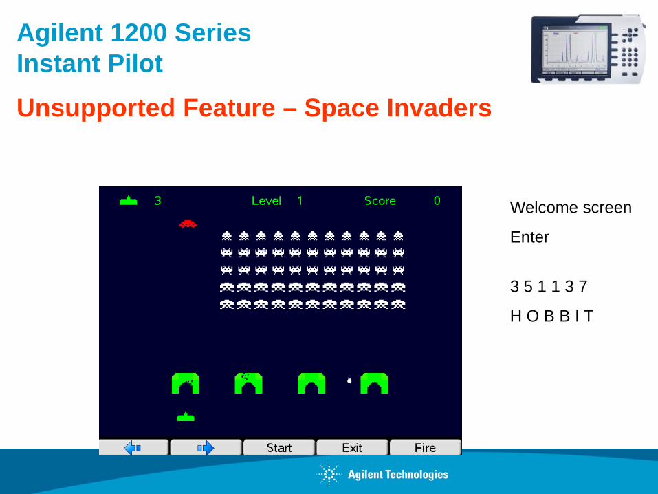
Agilent 1200 Series Instant Pilot
Unsupported Feature – Space Invaders
Welcome screen
Enter
3 5 1 1 3 7
H O B B I T

Use short, small internal diameter tubing between the injector and the column and between the column and the detector.
Make certain all tubing connections are made with matched fittings.
Use a low-volume detector cell.
Inject small sample volumes.
Increasing Extra-Column Volume
Extra-Column Dispersion

Dispersion is effected by
Tubing (amount and id) Connections (number of) Flow cell volume (larger >)
The goal is to have the smallest id tubing, least number of connections, and the lowest flow cell volume. This will give the best number for dispersion.

Dispersion
Flow rates converted for Column i.d. 4.6 mm Column 1.00 mL/min 3.0 mm Column 0.43 mL/min 2.1 mm Column 0.21 mL/min
Column Dimension Length = 50 mm Particle size = 1.8 µm
Efficiency Vs Dispersion Volume
Dispersion Volume (μl)

Dispersion
min 0.5 1 1.5 2 2.5
mAU
0
100
200
300
400
Excessive Dispersion Volume
Peakwidth 0.038 min
Peakwidth 0.037 min
Resolution 0.961
min 0.5 1 1.5 2 2.5
mAU
0
50
100
150
200
250
300 Optimised Dispersion Volume
Peakwidth 0.018 min
Peakwidth 0.019 min
Resolution 1.902

A typical chromatogram
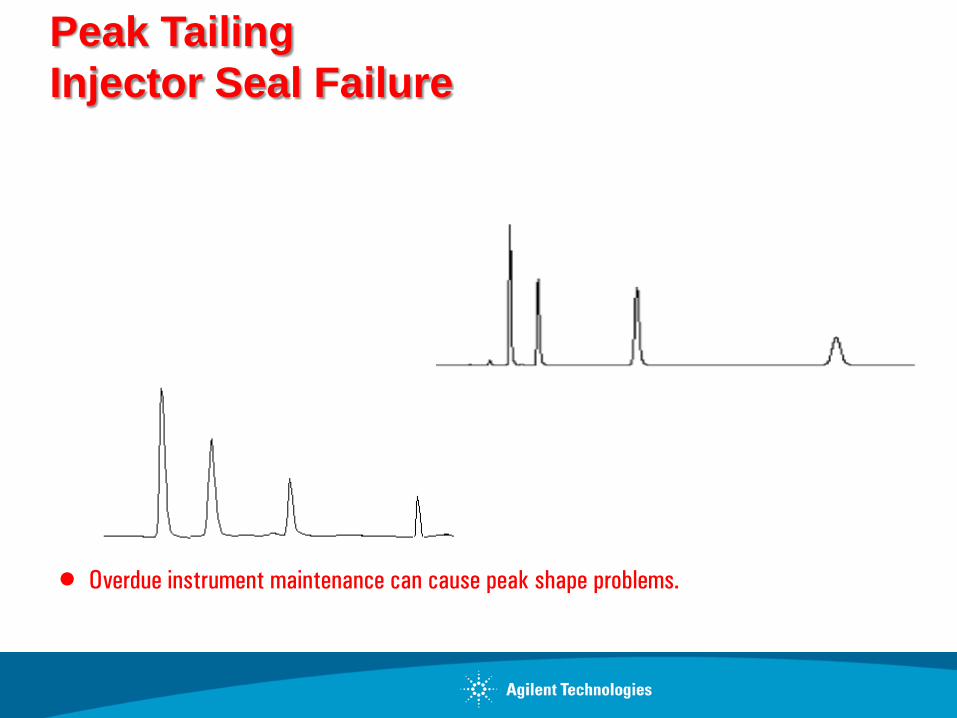
Peak Tailing Injector Seal Failure
• Overdue instrument maintenance can cause peak shape problems.
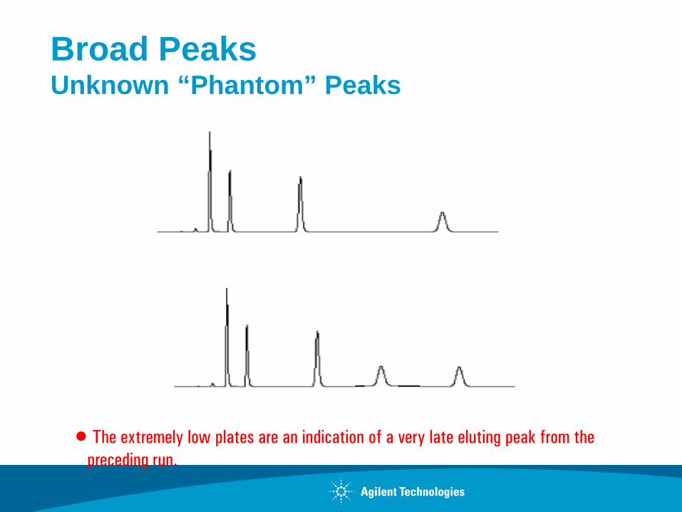
Broad Peaks Unknown “Phantom” Peaks
• The extremely low plates are an indication of a very late eluting peak from the preceding run.

Determining the Cause of Peak Tailing
• Evaluate mobile phase effects - alter mobile phase pH and additives to eliminate secondary interactions
• Evaluate column choice - try column with high purity silica or different bonding technology
• Reduce sample load
• Eliminate extra-column effects
• Flush column and check for aging/void
Group/Presentation Title Agilent Restricted
Month ##, 200X
Group/Presentation Title Agilent Restricted
Month ##, 200X
Questions?