1204e 60 kwe electropak there is insufficient cooling, contact perkins technical service department....
TRANSCRIPT

Technical Data1200 Series 1204E-E44TA
Electropak 60 kWe @ 1800 rpm
Basic technical data
Number of cylinders. ... ... ... ... ... ... ... ... ... ... ... ... ... ... ... ... ... .4 Cylinder arrangement .. ... ... ... ... ... ... ... ... ... ... ... Vertical in-line Cycle ... ... ... ... ... ... ... ... ... ... ... ... ... ... ... ... ... ... ... ... ..4 strokeInduction system.. ... ... ... ... ... ... ... .Turbocharged charge cooledCombustion system . ... ... ... ... ... ... ... ... ... ... Direct injection (DI)Compression ratio ... ... ... ... ... ... ... ... ... ... ... ... ... ... ... ... .16.5:1 Bore . ... ... ... ... ... ... ... ... ... ... ... ... ... ... ... ... ... 105 mm (4.13 in)Stroke .. ... ... ... ... ... ... ... ... ... ... ... ... ... ... ... ... 127 mm (5.00 in)Displacement ... ... ... ... ... ... ... ... ... ... ... ... ... 4.4 litres (268.5 in³)Direction of rotation when viewed from flywheel.. ... Anti-clockwiseDirection of rotation when viewed from front ... ... ... ... .. ClockwiseFiring order .. ... ... ... ... ... ... ... ... ... ... ... ... ... ... ... ... ... .1, 3, 4, 2Lifting points location ... ..Front left hand slide, rear right hand sideMobile use g-load limitations ... ... ... ... ... ... ... ... ... ... .. 2g vertical-est. total weight (dry) Including radiator support brackets .. 660 kg-est. total weight (wet) Including radiator support brackets . 680 kg
Overall dimensions-height, including radiator support brackets. ... ... ... ... ... 1126 mm-length, front of radiator to rear of air cleaner .. ... ... ... ... 1433 mm-width ... ... ... ... ... ... ... ... ... ... ... ... ... ... ... ... ... ... ... ... ..819 mm
Moments of inertia (mk²)Engine rotational inertia (excluding pulley and flywheel) .0.17 kgm²Crank pulley inertia (dependant on option code) . ... .Refer to ESMFlywheel inertia (dependant on option code)... ... ... .Refer to ESM
Centre of gravityForward from rear of block - wet.. ... ... ... ... ... ... ... ... ... ..260 mmAbove crankshaft centre line - wet... ... ... ... ... ... ... ... ... ..240 mmOffset to RHS of crankshaft centre line - wet... ... ... ... ... ... ..5 mm
Performance
Note: All performance data based on operation to ISO Standard reference: TR 14396.
All ratings certified to within . ... ... ... ... ... ... ... ... ... ... ... ... + 3%Speed variation at constant load ± ... ... ... ... ... ... ... ... ... .. 10 rpm
Test conditionsAir temperature . ... ... ... ... ... ... ... ... ... ... ... ... ... ... ... ... ... . 25°CBarometric pressure.. ... ... ... ... ... ... ... ... ... ... ... ... ... ... 101 kPaRelative humidity... ... ... ... ... ... ... ... ... ... ... ... ... ... ... ... ... 10.7%Air inlet restriction at maximum power (nominal) .. ... ... ... . 5.0 kPaExhaust back pressure at maximum power (nominal) .. ... 12.5 kPaFuel temperature (inlet pump)... ... ... ... ... ... ... ... ... ... ... .. 40.0°C
Noise data
Note: If the engine is to operate in ambient conditions other than those of the test conditions, suitable adjustments must be made for these changes. For full details, contact Perkins Technical Service Department.
Emissions statement:No enforced de-rate.
Radiated Sound Power Level (dB(A) ref. 1pW) @ 1800 rpm
At rated speed with pusher fan 110.6 dB(A)

General installation
Caution: The airflows shown in this table will provide acceptable cooling for an open power unit operating in ambient temperatures of up to 55°C (131°F) or 48°C (118.4°F) if a canopy is fitted with an air flow restriction of up to 120 Pa. If the power unit is to be enclosed totally, a cooling test should be done to check that the engine cooling is acceptable. If there is insufficient cooling, contact Perkins Technical Service Department.
Energy balance
Note: Energy balance referenced to absolute 0 Kelvin.
Units Prime Standby
Gross engine power (sales power) kWm 74.1 81.5
Fan and battery charging alternator power kW 5.5
Cooling fan airflow at zero duct - Dia. 559 mm pusher (including engine and core resistance) m³/sec 3.2
Radiator core resistance Pa 362
Fan power absorption kWm 4.6
Net engine power - full battery kWm 68.6 76.0
Torque gross Nm 392.7 432.0
Brake mean effective pressure kPa 1112 1239
Inlet air flow volume - wet m³/min 5.0 5.0
Exhaust gas flow - wet m³/min 12.0 13.0
Exhaust gas mass flow - wet kg/sec 6.0 6.1
Exhaust gas temperature (ex. Manifold / turbo outlet) °C 425.4 467.3
Exhaust gas flow (Max.) m³/min 13.0
Boost pressure ratio :1 2.19
Overall thermal efficiency (net) % 39 39
Assumed alternator efficiency % 87.2
Regenerative power estimated kW 12.8
Engine coolant flow - minimum against 35 kPa restriction l/min 159.0
Typical GenSet electrical output (0.8pf)kVA 68.2 75
kWe 54.5 60
Designation Units Prime Standby
Energy in fuel (fuel heat of combustion) kWt 189.0 209.7
Energy to power (gross) kWt 74.1 81.5
Energy to cooling fan - pusher kWm 4.6 4.6
Energy to power (nett) kWm 68.6 76.0
Heat rejection to radiator kWt 13.2 14.7
Energy to exhaust kWt 77.2 82.9
Energy to charge cooler kWt 6.4 6.5
Energy to radiation kWt 13.2 14.7

60 kWe @ 1800 rpm - left side view B
REAT
HER
REMO
VAL
204.6
REM
OVAL
20
420.8
8
365.4
70
233.5
108
135.6
409.5
1005.5
FUEL
IN10
9.6
FUEL IN19.3
55.6
94
172.2
107
119
REA
R LIF
TING
EYE
40
ECM
281
ECM97.5
76.2
31.2
225.1 R
ETUR
N TO
TANK
- cold
312
RETURN TOTANK-cold
261
568.5
17.5
49.2
431.8
479.5
640.1557
MAX
OI
L FILT
ER21
0.8
47.6
156.4
88.9
69
54
28.6
OVERALL1429
/ 00MK51619-DX_GA
LUB OIL DRAIN ZG OPTIONS
OIL SAMPLING VALVETAPPING-PLUGGEDM10 X 1
2-M10 X 1.5
4-M12 X 1.75BOTH SIDES
X
X
Y Y
X2
X2

60 kWe @ 1800 rpm - front view
OVE
RALL
1127
-TO 19 FRONTCUSTOMER MOUNTING HOLE 158
372
102
OVERALL813
2-11/16"-16 UNFMALE THREAD
DIPSTICK220.5
178
183
FRO
NT C
USTO
MER
MOUN
TING
262
372
720
375 377
141.6
243
-TO 19 FRONTCUSTOMER MOUNTING HOLE 158
560
209.6
/ 00MK51619-DX_GA
Z
Z
Y Y

60 kWe @ 1800 rpm - right side view
ALTERNATOR443.6
740.8
680
266
TO B
OTH
LIFTI
NG E
YES
565
BOTH SIDES220.6
55.6
225.2
AMB
IENT
TEMP
. SEN
SOR
156.6
AMBIENTTEMP. SENSOR6 O.
D.
76.3
STARTERBATTERY TERMINAL
167.1
81.5
422
137
145
533.4
TO 19 FRONT CUSTOMER MOUNTING HOLE - BOTH SIDES
698
431.8
479.5
17.5
49.2
217
451
SOO
T SE
NSOR
CON
NECT
OR70
1.6
SOOT SENSOR CONNECTOR990
47.6
88.9
76.2
24.3
/ 00MK51619-DX_GA
EARTH TERMINALM10 X 1.5
BATTERY TERMINALM10 X 1.5
4-M12 X 1.75BOTH SIDES
X
X
Y Y
X2
X2

60 kWe @ 1800 rpm - rear view
REMOVAL
17
AMBIENTTEMP. SENSOR
275.6OIL FILLER
248
OIL FILTER200
129.5 129.5
223.6
223.6
TO CUSTOMER MOUNTING HOLESFLYWHEEL HOUSING-BOTH SIDES
238.1
OIL SAMPLING221.9
FUEL IN235.3
FUELPUMP SENSOR
232.6
TO CUSTOMER MOUNTING HOLESCYL. BLOCK-BOTH SIDES144.5
RETURN TO TANK-HOT 256
ECM189
STARTERBATTERY TERMINAL269.4
STARTEREARTH TERMINAL243.3
255
136
160
82 115
145
180
136160
180
/ 00MK51619-DX_GA
12-M10 X 1.5 X 20 DRILL PATTERN FLANGE PATTERN TO No.3 S.A.E.
6-M12 X 1.75MOUNTING HOLESON FLYWHEEL HOUSING
Z
Z
Y Y
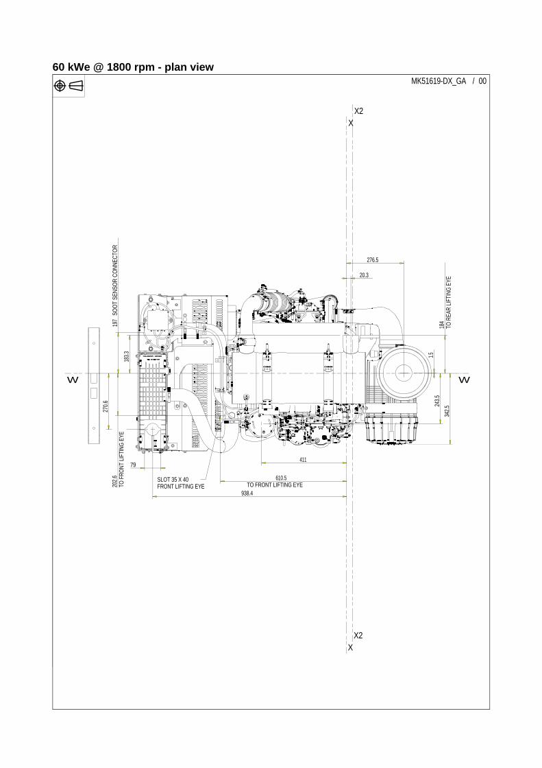
60 kWe @ 1800 rpm - plan view
276.5
1.5
342.5
938.4
270.6
79
183.3
20.3
TO FRONT LIFTING EYE 610.5
TO R
EAR
LIFTI
NG E
YE18
424
3.5
411
TO F
RONT
LIFT
ING
EYE
202.6
SOO
T SE
NSOR
CON
NECT
OR19
7
/ 00MK51619-DX_GA
SLOT 35 X 40FRONT LIFTING EYE
X
X
WW
X2
X2

Cooling system
Cooling packOverall weight (wet). ... ... ... ... ... ... ... ... ... ... ... ... ... ... ... ..52 kgOverall face area . ... ... ... ... ... ... ... ... ... ... ... ... ... ...0.455829 m²Width ... ... ... ... ... ... ... ... ... ... ... ... ... ... ... ... ... ... ... ...766.1 mmHeight .. ... ... ... ... ... ... ... ... ... ... ... ... ... ... ... ... ... ... ...886.1 mm
RadiatorFace area ... ... ... ... ... ... ... ... ... ... ... ... ... ... ... ... ...0.261145 m²Number of rows .. ... ... ... ... ... ... ... ... ... ... ... ... ... ... ... ... ... ... .3Matrix density and material.. ... ... ... ... ... ..10 fins/inch, AluminiumWidth of matrix. ... ... ... ... ... ... ... ... ... ... ... ... ... ... ... ...438.9 mmHeight of matrix ... ... ... ... ... ... ... ... ... ... ... ... ... ... ... ...595.0 mmPressure cap setting ... ... ... ... ... ... ... ... ... ... ... ... ... ...100.0 kPa
Charge coolerFace area ... ... ... ... ... ... ... ... ... ... ... ... ... ... ... ... ... .0.15093 m²Number of rows and material .. ... ... ... ... ... ... ... ... ..2, AluminiumMatrix density and material.. ... ... ... ... ... ..10 fins/inch, AluminiumWidth of matrix. ... ... ... ... ... ... ... ... ... ... ... ... ... ... ... ...258.0 mmHeight of matrix ... ... ... ... ... ... ... ... ... ... ... ... ... ... ... ...585.0 mm
FanType pusher ... ... ... ... ... ... ... ... ... ... ... ... ... ... ... ... ... ... M0013Diameter .. ... ... ... ... ... ... ... ... ... ... ... ... ... ... ... ... ... ... ..559 mmDrive ratio ... ... ... ... ... ... ... ... ... ... ... ... ... ... ... ... ... ... ... .1.33:1Number of blades ... ... ... ... ... ... ... ... ... ... ... ... ... ... ... ... ... ... .7Blade Material.. ... ... ... ... ... ... ... ... ... ... ... ... ... ... ... ..CompositeAirflow at rated speed (1800 rpm) ... ... ... ... ... ... ... ... ..3.2 m³/secPower absorbed @ 1800 rpm.. ... ... ... ... ... ... ... ... ... ... ... 4.6 kW
Coolant Total system capacity .. ... ... ... ... ... ... ... ... ... ... ... ... ... 18.3 litresBare engine capacity ... ... ... ... ... ... ... ... ... ... ... ... ... ... . 9.4 litresMaximum top tank temperature... ... ... ... ... ... ... ... ... ... ... .108°CThermostat operation range ... ... ... ... ... ... ... ... ... ... ... 82 - 94°CTemperature rise across engine (maximum)... ... ... ... ... ... ... .8°CCoolant pump drive . ... ... ... ... ... ... ... ... ... ... ... ... ... ... ... ...GearRecommended coolant immersion heater rating (minimum)0.6 kW
Recommended coolant BS6580 - 1992, and ELC coolants to 1E1966Duct Allowance (50% Glycol coolant)Maximum additional restriction (Duct allowance) to cooling airflow and resultant minimum airflow
M0013 pusher
Electrical system
Engine stop method.. ... ... ... ... ... ... ... ... ... ... ... ... ... ..Electronic
Cold start recommendations
Minimum battery cold cranking amps
Notes:Glow plugs needed below -10°CFor cable sizes see Applications and Installation manual.A
mbi
ent c
lear
ance
Duc
t allo
wan
ce
Coo
ling
fan
airf
low
Rad
iato
r cor
ere
sist
ance
Enginespeedrpm
°C Pa m³/sec Pa
1800 55 120 2.9 307
1800 48 200 2.7 268
Alternator Unit N0101
Alternator voltage Volts 12
Alternator output Amps 100
Starter Unit E0311
Starter motor voltage Volts 12
Starter motor power kW 3.0
Number of teeth on flywheel (D0004) 126
Number of teeth on starter pinion 10
Minimum cranking speed rpm
100 with glow plugs, 130
without glow plugs
Starter solenoid - Max. pull-in current @ -20°C Amps 68
Starter solenoid - Max. hold-in current @ -20°C Amps 20
Cold start recommendationMinimum battery Cold
Cranking Amps
With glow plugs 12v
-5 - 15W40 750
-10 - 15W40 750
-15 - 15W40 1650
-20 - 10W40 1650
-25 - 5W30 1500
Max. battery CCA. 2410

Exhaust system aftertreatment SF451
Aftertreatment system type.. ... ... ... ... ... ... ... ... ... DOC and DPFType of regeneration ... ... ... ... ... ... ... ... ... ... ... Low temperatureAftertreatment length ... ... ... ... ... ... ... ... ... 647.7 mm (25.5 Inch)Aftertreatment height ... ... ... ... ... Refer to GA as engine mounted Aftertreatment weight .. ... ... ... ... ... ... ... ... ... ... ... ... ... .. 31.0 KgOutlet orientation when viewed from rear of engine ... ... ... ... ... .... ... ... ... ... ... ... ... ... ... ... ... ... ... ... ... ... ... ...0 ° (horizontal RHS) Aftertreatment skin temperature .. ... ... ... ... ... ... ... ... ... ..250.0°CMax Temp for electronic components on aftertreatment . ..120.0°CMax Temp for external electronic components for Aftertreatment (soot sensor box) . ... ... ... ... ... ... ... ... ... ... 85.0°CTypical maximum temperature exhaust out. ... ... ... ... ... ... ... ... .... . Same as - exhaust gas temperature (Ex. Manifold / turbo outlet)Maximum system back pressure limit.. NA for engine mounted ATAftertreatment exhaust outlet connection ... ... ... ... ... ... .76.2 mmAftertreatment exhaust outlet connection load limit. ... ... . 60.0 NmAttenuation of the DPF ... ... ... ... ... ... ... ... ... ... ... ... ... NA dB(A)Ash service .. ... ... ... ... ... ... ... ... ... ... ... ... ... ... ... ..8000.0 hoursMaximum back pressure for customer installed pipe work.. 10 kPa
Induction system
Maximum air intake restrictionClean filter ... ... ... ... ... ... ... ... ... ... ... ... ... ... ... ... ... ... ...5.0 kPaDirty filter . ... ... ... ... ... ... ... ... ... ... ... ... ... ... ... ... ... ... ...8.0 kPaInduction indicator setting ... ... ... ... ... ... ... ... ... ... ... ... ...5.0 kPaAir filter type. ... ... ... ... ... ... ... ... ... ... ... ... ... ... ... ... ... ... ... ... .... ... ..Medium Duty: Specification – minimum dust-holding capacity (tested to S.A.E J726b or ISO 5011): 10 gram SAE coarse test dust/cu. ft./min of airflow
Fuel injection system Fuel pump type / model ... ... ... ... ... ... ... ... ... ... ... ... ... ... ... HP3Injection system... ... ... ... ... ... ... ... ... ... ... ... ... ... .. Common railInjector type . ... ... ... ... ... ... ... ... ... ... ... ... ... ... ... ... ... .SolenoidInjection pressure ... ... ... ... ... ... ... ... ... ..Electronically governed
Fuel Priming Priming pump type... ... ... ... ... ... ... ... ... ... ... ... ... ... ... ...ElectricMaximum priming time ... ... ... ... ... ... ... ... ... ... ... ... 90 seconds
Fuel feedMaximum fuel supply restriction at primary filter . ... ... .50 kPa absMaximum fuel return restriction at low idle .. ... ... ... ... ... ... 20 kPaMaximum fuel return flow ... ... ... ... ... ... ... ... ... ... ... ... 1.74 l/minMaximum fuel flow through inlet connection ... ... ... ... ... . 2.6 l/minMaximum lift pump delivery pressure .. ... ... ... ... ... ... ... ..450 kPaMaximum suction head at fuel pump inlet. .. ... ... ... ...150 kPa absMaximum static pressure head ... ... ... ... ... ... ... ... ... ... ... 20 kPaMaximum fuel temperature at lift pump inlet.... ... ... ... ... ... ...80°CMaximum fuel filter service interval . ... ... ... ... ... ... ... ... ...500 hrs
Fuel specification
ULSD (Ultra Low Sulphur Diesel) 15ppm Sulphur
Fuel consumption (SFC)
Lubrication system (G0100)
Maximum system capacity ... ... ... ... ... ... ... ... ... ... ... ...8.1 LitresMaximum capacity in sump... ... ... ... ... ... ... ... ... ... ... ...7.0 LitresMinimum capacity in sump ... ... ... ... ... ... ... ... ... ... ... ...5.6 LitresMaximum oil temperature continuos operation . ... ... ... ... ... 125°CMaximum oil temperature intermittent operation... ... ... ... ... 135°C
Lubricating oil pressureAt rated speed... ... ... ... ... ... ... ... ... ... ... ... ... ... .. 360 - 440 kPaMinimum ... ... ... ... ... ... ... ... ... ... ... ... ... 250.0 kPa @ 1000 rpmOil relief valves opens at... ... ... ... ... ... ... ... ... ... ... 545 - 595 kPaSump drain plug tapping size or hose connection size ... ... ... ... ... ... ... ... ..3/4 UNF STOR portOil pump drive method... ... ... . Gerotor (gear driven off crankshaft)Oil pump speed ... ... ... ... ... ... ... ... ... ... ... ... .. 2 x engine speedLubricating oil flow at rated speed ... ... ... ... ... ... ... . 50 litres/min.Oil consumption at full load rated speed .. ... ... ... . 0.065 % of fuel
Recommended SAE viscosity
A multigrade oil conforming to API-CJ4, ACEA-E9, ECF3 must be used.
Normal operating angles
Front and rear ... ... ... ... ... ... ... ... ... ... ... ... ... ... ... ... ... ... ... 25°Side... ... ... ... ... ... ... ... ... ... ... ... ... ... ... ... ... ... ... ... ... ... ... 25°
Load g/kW.hr litres/hr25% 292 6.650% 234 10.575% 217 14.7
100% (Prime) 212 19.0110% (Standby) 211 21.1
Viscostiy grade
-50 -40 -30 -20 -10 0 10 20 30 40 50 60
0W-20
0W-30
0W-40
5W-30
5W-40
10W-30
10W-40
15W-40
Ambient temperature °C

1200 Series 60 kWe @ 1800 rpm
erki
ns E
ngin
es C
ompa
ny L
imite
d.
PTO capabilities
Q1030
Note: Refer to “Applications and Installation Manual” for “PTO approval requirements”.
Mountings
Note: Refer to “Applications and Installation Manual” for “Bending Moment approval requirements”.
Flange type SAE A
Torque capability intermittent 210 Nm
Torque capability continuous 142 Nm
Max. bending moment at flange 0 Nm
Maximum static bending moment at rear face of block
NmCalculate based on
dynamic limit and intended installation g load
Maximum permissible load applied to rear of crankshaft (vertically down)
kN 1.6
Maximum permissible bending moment(in vertical direction) at crankshaft rear mounting face
Nm 54
Maximum permissible front and rear crankshaft overhung load capability
N See OHL polar diagrams in ESM
Max. bending momentat rear of flywheel housing (Nm) - SAE 3
Nm
Dynamic vertical bending moment. Nm ± 3000NmDynamic lateral bending moment. Nm ±1700Nm
All information in the document is substantially correct at the time of printing but may be subsequently altered by the company.
Distributed by
Pub
licat
ion
No.
TP
D17
82E
1, 1
0 N
ovem
ber 2
011.
© P
Perkins Engines Company LimitedPeterborough PE1 5NA United KingdomTelephone +44 (0) 1733 583000Fax +44 (0) 1733 582240www.perkins.com