120cc slick 580 arf - extreme flightextremeflightrc.com/assets/images/manuals/extreme flight 105...
TRANSCRIPT

1
120cc SLICK 580
ARF Assembly Manual
Copyright 2017 Extreme Flight RC
2
Please take a few moments to read this instruction manual before beginning
assembly. We have outlined a fast, clear and easy method to assemble this
aircraft and familiarizing yourself with this process will aid in a quick, easy
build.
Please read the following paragraph before beginning assembly of your
aircraft! THIS IS NOT A TOY! Serious injury, destruction of property, or
even death may result from the misuse of this product. Extreme Flight is
providing you, the consumer, with a very high quality model aircraft
component kit, from which you, the consumer, will assemble a flying model. It
is beyond our control to monitor the finished aircraft you produce. Extreme
Flight RC will in no way accept or assume responsibility or liability for
damages resulting from the use of this user assembled product.
This aircraft should be flown in accordance with the AMA safety code. It is
highly recommended that you join the Academy of Model Aeronautics in
order to be properly insured and operate your model at AMA sanctioned
flying fields only. If you are not willing to accept ALL liability for the use of
this product, please return it to the place of purchase immediately.
Extreme Flight RC, Ltd. guarantees this kit to be free of defects in materials
and workmanship for a period of 30 DAYS from the date of purchase. All
warranty claims must be accompanied by the original dated receipt. This
warranty is extended to the original purchaser of the aircraft kit only.
Extreme Flight RC in no way warranties its aircraft against flutter. We have
put these aircraft through the most grueling flight tests imaginable and have
not experienced any control surface flutter. Proper servo selection
and linkage set-up is absolutely essential. Inadequate servos or improper
linkage set up may result in flutter and possibly the complete destruction of
your aircraft. If you are not experienced in this type of linkage set-up or have
questions regarding servo choices, please contact us at
[email protected] or 770-887-1794. It is YOUR responsibility to
ensure the airworthiness of your model.

3
Congratulations on your purchase of the Extreme Flight RC 120cc Slick 580
EXP! Designed by Extreme Flight and developed by Jase Dussia, the Slick
580 was conceived as a no holds barred, no excuses all out Freestyle
competition machine. The first prototypes were sent directly to the Dussia's
in Michigan in the Summer of 2016. The aircraft were assembled, setup and
dialed in. A few short weeks later Jase won the 2016 Clover Creek
Invitational Freestyle competition with his new Slick! After the contest
further testing was conducted and minor tweaks were made to the airframe to
improve strength while reducing weight. Extreme Flight returned to China in
November 2016 to oversee the implementation of the final changes and
tweaks. Now the Slicks are here, and ready to usher in a new era in 120cc
Aerobatic performance!
The new Slick 580 is a masterpiece of integrated carbon and composite
reinforced balsa airframe design. Strong, rigid and lightweight with a state of
the art aerodynamic package, the Slick excels at XA, 3D and precision
aerobatics and is probably the fastest rolling giant scale aerobatic plane in
existence. Extreme Flight and Jase evaluated various airfoils, multiple wing
planform details, several rudder designs, and more to maximize all these
characteristics. Highly stylized with flowing lines and curves reminiscent of a
composite airframe, the Slick 580 is simply gorgeous. Currently available in 2
Arron Bates designed ultra modern Ultracote color schemes, the Slick will
also be available in Jase's printed competition scheme very soon.
The Slick ships with a complete hardware package that is competition proven
and exactly what Jase uses in his models. It also includes a set of engine
baffles that can be trimmed to accommodate most makes of 100-120cc
engines. Rig out your model just like Jase's with our line of Xcessories
including Flowmaster tanks, EF fuel dots, 20 AWG twisted servo extensions,
high quality aluminum servo arms, MKS servos and DA engines.
If you are looking for the pinnacle of competition level ARF aircraft, here it
is!

4
Items needed for completion:
Hobby knife with #11 blades
30 minute epoxy. Pacer Z-Poxy has worked very well for us for many years
Blue and Red Loctite
Electric drill with an assortment of drill bits
Small flat head and Phillips head screw drivers
Standard and needle nose pliers
Side cutters
Metric ball driver or allen key set. (especially 2.5 and 4mm drivers)
Sanding block and sandpaper
Extreme Flight Servo Mounting Screws
7 400oz (min) torque metal gear servos (8 servos if you use 2 rudder servos)
1 x standard size servo for the throttle
4 x Extreme Flight 1.5” single aluminum Servo Arms for the ailerons
2 x Extreme Flight 2” single aluminum arms for the elevators
1 x Extreme Flight 1.5" single aluminum servo arm for rudder if using single
rear mounted servo
1 x Extreme Flight 4” double offset aluminum arm for the rudder if using pull
pull rudder setup.
2 x 6” Extreme Flight 20 AWG Servo Extensions for inboard aileron servo
3 X 24" Extreme Flight 20 AWG Servo Extensions (2 outboard ailerons 1 for
throttle)
3 x 48” Extreme Flight 20 AWG Servo Extensions elevators and rear mounted
rudder servo.
2 x Extreme Flight multi-plug sets (optional but a great convenience)
5” Spinner
85cc-120cc gas engine and recommended prop and mufflers/canisters/pipes
Blazing Star DA 120cc engine mount
EF Flowmaster 34 ounce fuel tank and tubing, EF FUEL DOT.
Receiver, batteries, switches

5
Tips for Success:
1. Before starting assembly, take a few minutes to read the entire
instruction manual to familiarize yourself with the assembly process.
2. Go over all the seams on the aircraft with a covering iron on a
medium heat setting. Also, due to climate changes, wrinkles may
develop in the covering. These are easily removed with a little bit of
heat. Use a 100% cotton tee-shirt or microfiber cloth and your heat gun
and heat the covering while gently rubbing the covering onto the wood
with the cloth. Be careful not to use too much heat as the covering may
shrink too much and begin to lift at the edges. Take your time, and a
beautiful, paint-like finish is attainable.
3. Apply CA to high stress areas such as servo mounting trays, landing
gear mounts, anti-rotation pins, wing and stab root ribs, wing mounting
tabs and motor box joints etc.
4. By the time your aircraft arrives at your door step, it will have been
handled by a lot of people. Occasionally there are small dings or
imperfections on some of the surfaces. An effective method to restore
these imperfections to original condition is to use a very fine tipped
hypodermic needle and inject a drop of water under the covering
material and into the ding in the wood. Apply heat to the area with a
sealing iron and the imperfection will disappear. Deeper marks may
require that this process be repeated a couple of times to achieve the
desired result, but you will be surprised at how well this technique
works.
5. Use high quality, fresh epoxy for installing the composite control
horns and hinges. We highly recommend Pacer Z-Poxy 30 minute
Epoxy. We are very pleased with the results and ease of application and
cleanup of these products.
6. Take the time to properly balance and trim your aircraft and set up
rates with exponential values. Your flying experience will be greatly
enhanced once your plane is properly dialed in.
7. Extreme Flight now has their own Vimeo channel. There are many
assembly videos providing extreme detail on certain aspects of the
assembly. https://vimeo.com/extremeflightrc

6
Let's Begin:
1. Locate the wing panels/ailerons and horizontal stabilizers/elevators and
associated hardware bags. We will begin by hinging all of these at one time.
I strongly recommend 30 minute (or slower curing) epoxy for installing
hinges. I have found it easier to apply 3-5 drops of glue in the hinge hole and
then using a toothpick, or similar, spread the glue around the sides of the
hinge hole. Do this on just one side of the surface at a time. Before applying
any glue to the hinge itself, I highly recommend you protect
the hinge pin (pivot point) from glue. I use Vaseline. Tape will work however
it is harder to remove later. In any case apply either protectant to the center
of the hinge so glue cannot penetrate the pin. Once you have the holes lathered
with glue, apply a small amount to the hinge barbs and insert into the hinge
hole until the pin is even with the hinge line. Be sure your hinge pivots freely
and is perpendicular to the hinge line. Allow to dry then mate to the
appropriate surface (wing to
aileron/horizontal stabilizer to elevator) and allow to dry. ***PLEASE
NOTE*** there are 3 hinges that have been shortened to clear the tube
socket. They are glued into the 3 inboard positions as shown.

7
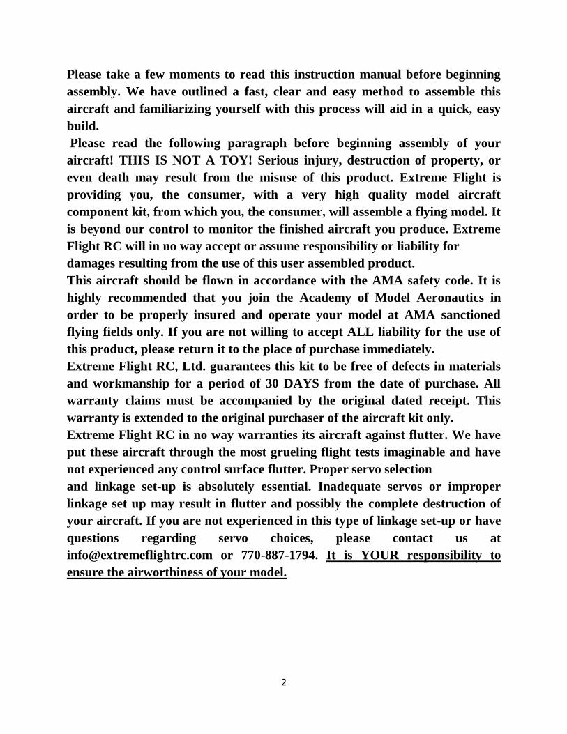
2. Install the control horns for the ailerons. ***PLEASE NOTE*** There are
2 different size control horns for the ailerons. The 2 longer sets are for the
outboard aileron servos, the 2 shorter sets are for the inboard locations. Pay
very close attention when separating and grouping the horns to be sure you
are gluing the correct horns in the correct location!
Insert the horns into the base plate and then temporarily install them in the
aileron. Trace around the base plate with a fine tipped felt marker and then
remove the horn and base plate. Use a sharp hobby knife to cut 2mm inside
the line you marked and remove the covering. Scuff the bottom portion of the
control horn that inserts into the hole in the control surface. Use epoxy to
secure the control horns in place. Follow the same process to install the
elevator control horns in the designated locations.
8
9
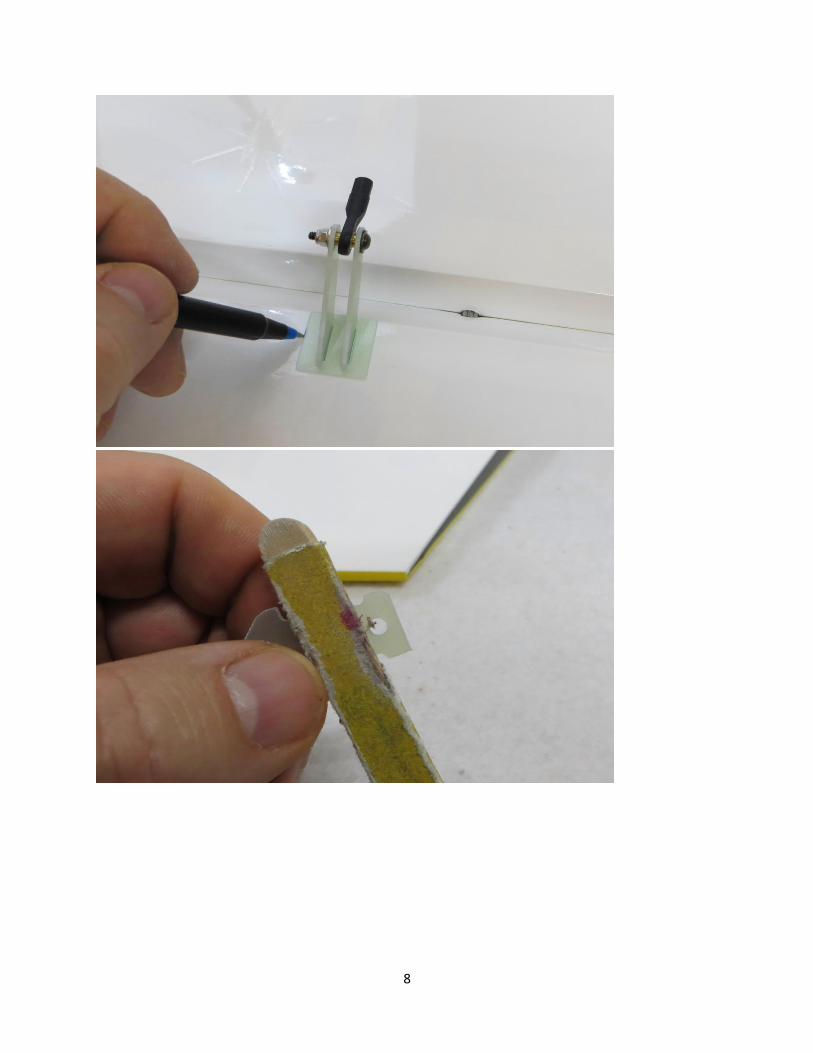
3. Install the aileron servos and orient the output shaft of the servo towards
the hinge line. You will notice there are 2 types of ball links included: one
standard ball link and one with a built in riser. The standard ball link is
sandwiched between the control horns, the ball link with the riser is secured
to the aluminum servo arm. Thread the ball links onto each end of the
turnbuckle pushrod. You may find it necessary to shorten the pushrods
slightly (2mm) on each end with a pair of side cutters for best fit. To secure
the ball link to the control horns insert the 3mm bolt with integrated washer
thru the control horn, then the ball link in the middle, then thru the other
control horn, then the washer and nylon insert nut onto the other side.
Electronically center your servo and install the aluminum arm perpendicular
to the servo case. Secure the ball link with the riser to the servo arm. Do the
same for the other servo locations. You will need to use the servo matching
function in your radio or an external device to make sure the 2 aileron servos
are perfectly synchronized and causing no binding. Failure to do so can
destroy your servos in short order.

10

11
4. Install the elevator servos, orient the output shaft toward the hinge line of
the horizontal stabilizer. It will be easier to install the servo arms after
mounting the servo. Make all hookups for the pushrods/ball links as we did in
the previous step. I recommend using the 1.75" location on the 2 inch servo
arm to maximize mechanical advantage and minimize the chance of flutter.
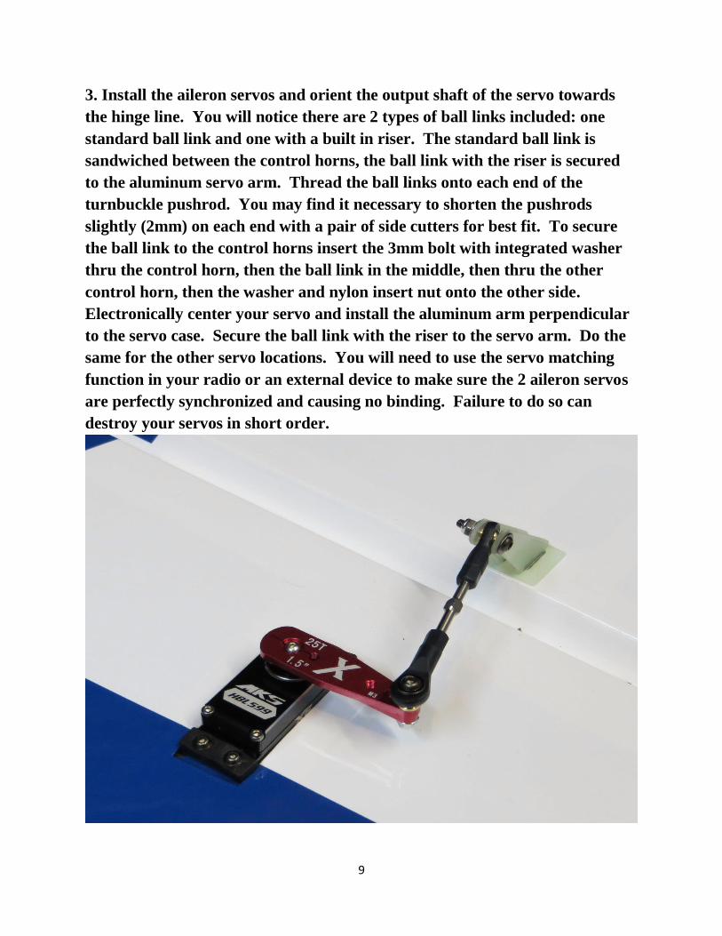
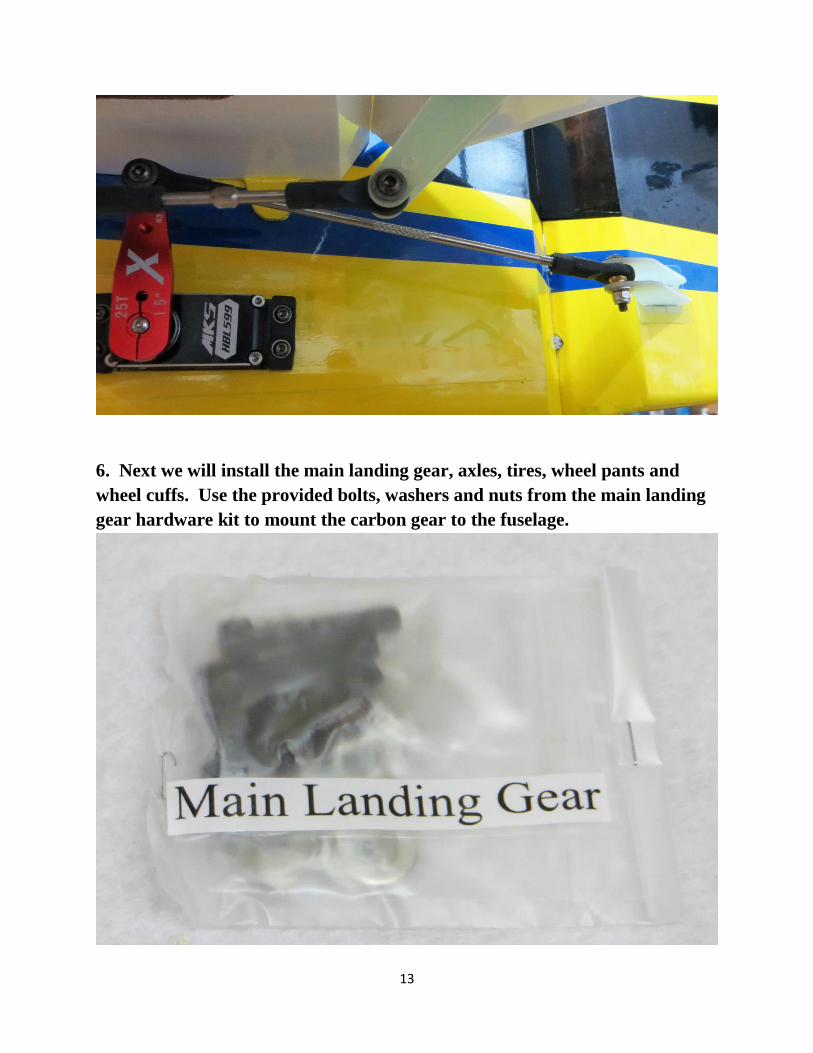
5. Hinge the rudder and install the control horns using the same technique(s)
as the wing. For most installations a single ultra high torque servo mounted
in the rear of the plane will be the ideal way to power the rudder. We highly
recommend the MKS HBL380 or 599 for this location. A single 1.5"
aluminum servo arm will provide plenty of travel while maintaining the best
mechanical advantage and servo resolution. Please see the following photo of
this setup for detail. If using a pull-pull setup you will need to glue a horn set
to each side of the rudder and use a 4" double arm on the servo mounted
under the canopy.
12
13
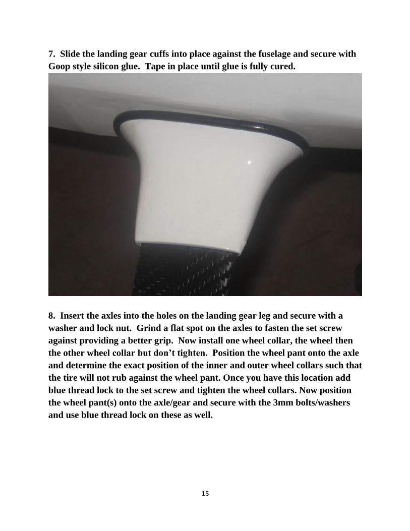
6. Next we will install the main landing gear, axles, tires, wheel pants and
wheel cuffs. Use the provided bolts, washers and nuts from the main landing
gear hardware kit to mount the carbon gear to the fuselage.

14
15
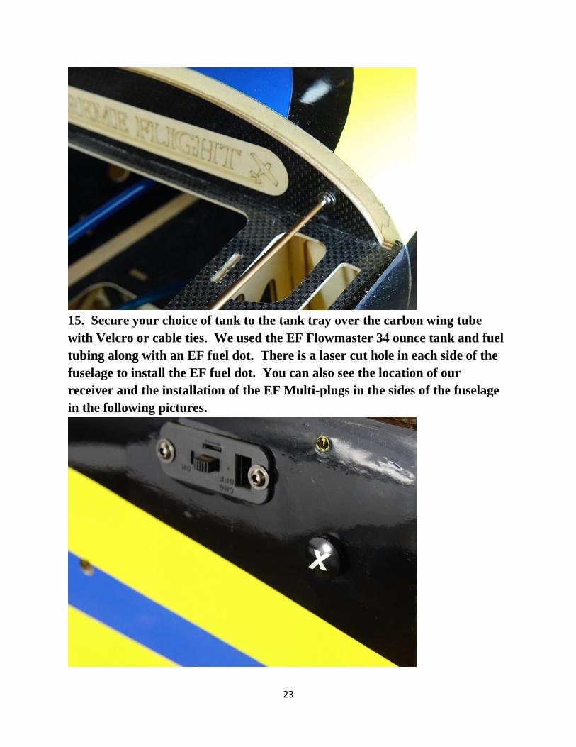
7. Slide the landing gear cuffs into place against the fuselage and secure with
Goop style silicon glue. Tape in place until glue is fully cured.
8. Insert the axles into the holes on the landing gear leg and secure with a
washer and lock nut. Grind a flat spot on the axles to fasten the set screw
against providing a better grip. Now install one wheel collar, the wheel then
the other wheel collar but don’t tighten. Position the wheel pant onto the axle
and determine the exact position of the inner and outer wheel collars such that
the tire will not rub against the wheel pant. Once you have this location add
blue thread lock to the set screw and tighten the wheel collars. Now position
the wheel pant(s) onto the axle/gear and secure with the 3mm bolts/washers
and use blue thread lock on these as well.

16

17
9. Next we will install the tailwheel. Notice there is a 3mm hole in the bottom
of the rudder about 3" inches from the hinge line. Remove the covering over
this hole and then glue the included ball link into this hole with epoxy. You
will also notice that the mounting plate for the tailwheel assembly is recessed.
Remove the covering from this area to expose the mounting plate and 3
mounting holes. Use 3 of the included 3mm bolts to install the tailwheel
assembly to the fuselage, using blue Loctite on each bolt. Before installing the
tailwheel assembly we highly recommend that you remove all set screws in the
unit and apply blue Loctite to each of them before reassembly.

18

19
10. Next we'll install the engine. There are laser marked locations to drill if
using the DA-120. There is also a laser scribed cross to use a template for
other engine makes. Drill for 1/4x20 mounting bolts at the proper locations.
11. Install the DA-120 using the Blazing Star 1 inch mount and the single
3mm Delrin spacer provided with the mount. Be sure the spacer goes between
the mount and plywood firewall, not against the engine. Secure using 1/4x20
bolts, washers and lock nuts (not included). Total distance from the front of
the motor box to the rear of the spinner backplate is 7.35" or 187mm.

20
12. The following picture shows the location I mounted my throttle servo as
well as the mufflers installed. Use a rotary tool to open the bottom of the cowl
to fit the mufflers and to provide an exit for air. Notice I've also made a hole
so that I can reach the choke lever easily with my finger. I find this easier
than a dedicated choke servo installation and you save the weight of the servo
and linkage. Some folks prefer to use a choke servo and that works great as
well.

21

22
13. A set of engine baffles has been provided to duct air over the engine
cylinders. These will need to be trimmed to fit your chosen engine. Glue in
place with Goop or epoxy.
14. Mount the cowl using the 3 3mm socket head cap screws and washers.
The longest of the 3 bolts is used to secure the bottom of the cowl and the
remaining bolts secure the top of the cowl as shown. Be sure to use blue
Loctite on these bolts.
23
15. Secure your choice of tank to the tank tray over the carbon wing tube
with Velcro or cable ties. We used the EF Flowmaster 34 ounce tank and fuel
tubing along with an EF fuel dot. There is a laser cut hole in each side of the
fuselage to install the EF fuel dot. You can also see the location of our
receiver and the installation of the EF Multi-plugs in the sides of the fuselage
in the following pictures.

24
16. When preparing the Slick for flight, slide the stab tube into the socket in
the rear of the model. Slide the stab onto the tube and secure the servo lead to
the servo extension with heat shrink tubing (or an EF servo safety clip as
shown if you plan to remove the stabs for transport). Secure the stab with 2
3mm bolts and washers as shown (be sure to put blue Loctite on the bolts!)
Repeat for the other stab.
25
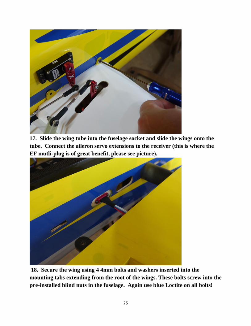
17. Slide the wing tube into the fuselage socket and slide the wings onto the
tube. Connect the aileron servo extensions to the receiver (this is where the
EF mutli-plug is of great benefit, please see picture).
18. Secure the wing using 4 4mm bolts and washers inserted into the
mounting tabs extending from the root of the wings. These bolts screw into the
pre-installed blind nuts in the fuselage. Again use blue Loctite on all bolts!

26
19. A set of SFGs and wing tips are included. They are secured with 3 mm
bolts. We suggest you experiment with each configuration and decide which
works best for your flying style. Attaching the racing wing tips will slow the
roll rate slightly which some flyers may find beneficial. It will also add to the
effective wing area of the model
20. Install your ignition and flight batteries where needed to help achieve
proper CG.
Set-up and trimming Besides basic assembly, this is the most important part of preparing your
airplane for flight. It can also be the most time consuming, but once your
plane is properly dialed in you will agree it was time well spent. The CG range
basically extends over the width of the wing tube. One of the most practical
ways to check the CG on an aircraft this size is to insert the carbon fiber wing
tube into its sleeve in the fuselage and tie a length of rope around the tube on
each side of the fuselage, forming a loop that you can pick the aircraft up
with. Slide the wings into position, install the canopy and pick up the plane
with the rope. The Slick should balance in a horizontal position. Move your
batteries and radio equipment to achieve this condition. This will give you a
safe starting place for the first flights. One of the best ways to fine tune the
CG for your aircraft is the 45 degree line test. Fly the aircraft in front of you
from left to right (or right to left if you prefer) at full throttle. Pull the aircraft
into a 45 degree up line and establish this line. Roll the aircraft inverted,
neutralize the elevator and pay close attention to what the plane does. Ideally
the plane will continue on this line for several hundred feet before it starts to
slowly level off. If the airplane immediately drops the nose and dives toward
the ground it is nose heavy. If it begins to climb inverted toward the gear it is
tail heavy. There is no need to have the Slick 580 excessively tail heavy to
perform 3D maneuvers.

27
Control surface throws I highly recommend that you purchase a throw meter that measure in
degrees. There are several units available commercially. These units are a
great aid in set-up and definitely beat the “that looks about right” method.
For any type of precision flying, surfaces that travel equal distances are a
must. The following control surface travels are what I use on my own Slick.
These are a good starting point, but are by no means the only way to set up
the aircraft. Start here and then adjust to fit your own preferences and style
of flying.
Elevator: 8-10 degrees low rate, 20% exponential; all you can get high rate,
60-65% exponential
Aileron: 20 degrees low rate, 30-40% exponential; 38-45 degrees high rate,
65-70% exponential
Rudder: 20 degrees low rate, 50% exponential; all you can get for high rate,
80-90% exponential.
This completes the assembly of the Slick 580 EXP. As a final step clean the
entire aircraft with glass cleaner, then apply a coat of spray-on wax and buff
the finish to a high gloss with a microfiber cloth. My favorite product for this
is Eagle One Wet Wax AS-U-DRY, available in the automotive section of most
Wal-Marts, K-marts, Sears, Targets, etc. People often ask me at trade shows
how I get the planes to look so shiny, this is my secret. You may wish to apply
all of your graphics before applying the coat of wax.
Thanks again for your purchase of the Extreme Flight RC 120cc Slick 580
EXP. I hope you enjoy assembling and flying yours as much as I have mine.
See you at the flying field!
Chris Hinson