1242 laser transmitter guide • introduction thank you for choosing the 1242 spectra precision...
TRANSCRIPT
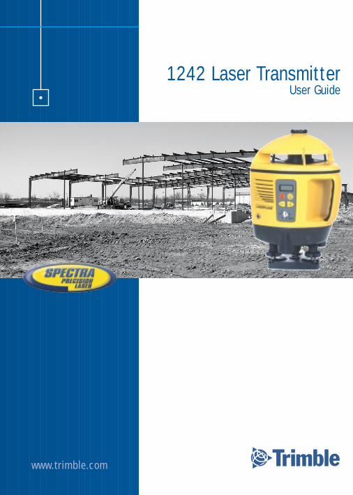
1242 Laser TransmitterUser Guide
www.trimble.com
•

Introduction
Thank you for choosing the 1242 Spectra Precision Laser from the Trimble family of precision lasers. You’ve just made a wise investment in field-proven products made by the world’s largest manufacturer of laser-based leveling, alignment, and grade-control systems.
The 1242 is a simple-to-use tool that allows you to take accurate horizontalmeasurements up to 60 m (200 ft) away visually or 400 m (1300 ft) away using a hand-held receiver. Each system component is designed for ALL construction levelingand surveying tasks requiring tight tolerances…under all environmental conditions.
This manual introduces you to the 1242 laser system. Use the manual now to learnbasic skills, and use it later as a reference book. You don’t need to know anything aboutthe 1242 laser to use this manual. Everything you need to know is explained as you goalong. The great thing about this laser system is that once you learn a few techniques,you’ll use those same techniques whenever you use this system—no matter what yourleveling requirements are.
You’ll get years of service from your reliable, state-of-the-art system by following therecommendations in this manual. Your comments and suggestions are welcome; pleasecall the Trimble Engineering and Construction Division for your local, authorizedTrimble office.
Trimble Engineering and Construction Division5475 Kellenburger RoadDayton, Ohio 45424-1099 U.S.A.Phone: (937) 233-8921
(800) 538-7800Fax: (937) 233-9004Internet: www.trimble.com
i

Claim for Damage in Shipment
The 1242 laser system includes a laser, receiver, quick clamp, operator’s manual, lasersafety kit, carrying case, and batteries. Optional accessories include a scope and batteryrecharging kit.
You should inspect your laser system as soon as you receive it. It has been packaged forsafe delivery. If it is damaged in any way, immediately file a claim with the carrier or, ifinsured separately, with the insurance company.
Safety Information
Included in this manual are CAUTIONS and Notes. Each of these words represents alevel of danger or concern.
A CAUTION indicates a hazard or unsafe practice that could result in minor injury orproperty damage.
A Note indicates important information unrelated to safety.
ii
Table of Contents
PageIntroduction . . . . . . . . . . . . . . . . . . . . . . . . . . . . . . . . . . . . . . . . . . . . . . . . iClaim for Damage in Shipment . . . . . . . . . . . . . . . . . . . . . . . . . . . . . . . . . . iiSafety Information . . . . . . . . . . . . . . . . . . . . . . . . . . . . . . . . . . . . . . . . . . . . iiTable of Contents. . . . . . . . . . . . . . . . . . . . . . . . . . . . . . . . . . . . . . . . . . . . . iiiFeatures & Functions . . . . . . . . . . . . . . . . . . . . . . . . . . . . . . . . . . . . . . . . . . 1
Laser . . . . . . . . . . . . . . . . . . . . . . . . . . . . . . . . . . . . . . . . . . . . . . . . . 1How to Use the 1242 Laser System . . . . . . . . . . . . . . . . . . . . . . . . . . . . . . . . 4
Laser . . . . . . . . . . . . . . . . . . . . . . . . . . . . . . . . . . . . . . . . . . . . . . . . . 4Installing the Batteries . . . . . . . . . . . . . . . . . . . . . . . . . . . . . . . . . . 4Attaching the Laser to a Tripod . . . . . . . . . . . . . . . . . . . . . . . . . . . 5Setting Up the Laser in Automatic Self-Leveling Mode . . . . . . . . . . 6Setting Up the Laser in Grade Mode . . . . . . . . . . . . . . . . . . . . . . . 8Setting Up the Laser in Manual Mode . . . . . . . . . . . . . . . . . . . . . . 10
General Construction Uses . . . . . . . . . . . . . . . . . . . . . . . . . . . . . . . . . 12Determining the Height of Instrument (HI). . . . . . . . . . . . . . . . . . 12Establishing 4-Foot (1-Meter) Reference Marks . . . . . . . . . . . . . . . 13Determining the Difference in Elevation . . . . . . . . . . . . . . . . . . . . 16Using the Point-Control Knob for Grade-Axis-Alignment
Applications . . . . . . . . . . . . . . . . . . . . . . . . . . . . . . . . . . . . . . . 18General Application . . . . . . . . . . . . . . . . . . . . . . . . . . . . . . . . . 18Short-Run Pipe Laying Application. . . . . . . . . . . . . . . . . . . . . . 19
Specifications . . . . . . . . . . . . . . . . . . . . . . . . . . . . . . . . . . . . . . . . . . . . . . . . 20Maintenance and Care . . . . . . . . . . . . . . . . . . . . . . . . . . . . . . . . . . . . . . . . . 21
Storage . . . . . . . . . . . . . . . . . . . . . . . . . . . . . . . . . . . . . . . . . . . . . . . 21Battery Disposal . . . . . . . . . . . . . . . . . . . . . . . . . . . . . . . . . . . . . . . . . 21System Cleaning . . . . . . . . . . . . . . . . . . . . . . . . . . . . . . . . . . . . . . . . 21
Troubleshooting . . . . . . . . . . . . . . . . . . . . . . . . . . . . . . . . . . . . . . . . . . . . . . 22Calibration. . . . . . . . . . . . . . . . . . . . . . . . . . . . . . . . . . . . . . . . . . . . . . . . . . 23Service . . . . . . . . . . . . . . . . . . . . . . . . . . . . . . . . . . . . . . . . . . . . . . . . . . . . . 27Laser Safety . . . . . . . . . . . . . . . . . . . . . . . . . . . . . . . . . . . . . . . . . . . . . . . . . 30EMC Declaration of Conformity . . . . . . . . . . . . . . . . . . . . . . . . . . . . . . . . . 32Warranty . . . . . . . . . . . . . . . . . . . . . . . . . . . . . . . . . . . . . . . . . . . . . . . . . . . 33
iii
6
1
5
3
4
7
2
1
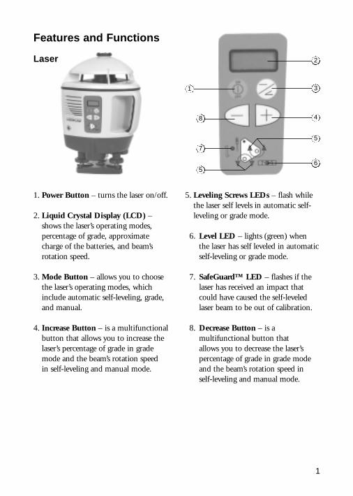
5. Leveling Screws LEDs – flash whilethe laser self levels in automatic self-leveling or grade mode.
06. Level LED – lights (green) when the laser has self leveled in automaticself-leveling or grade mode.
07. SafeGuard™ LED – flashes if thelaser has received an impact thatcould have caused the self-leveledlaser beam to be out of calibration.
08. Decrease Button – is amultifunctional button that allows you to decrease the laser’spercentage of grade in grade modeand the beam’s rotation speed in self-leveling and manual mode.
1. Power Button – turns the laser on/off.
2. Liquid Crystal Display (LCD) –shows the laser’s operating modes,percentage of grade, approximatecharge of the batteries, and beam’srotation speed.
3. Mode Button – allows you to choosethe laser’s operating modes, whichinclude automatic self-leveling, grade,and manual.
4. Increase Button – is a multifunctionalbutton that allows you to increase thelaser’s percentage of grade in grademode and the beam’s rotation speed in self-leveling and manual mode.
8
5
Features and Functions
Laser
Laser (cont.)
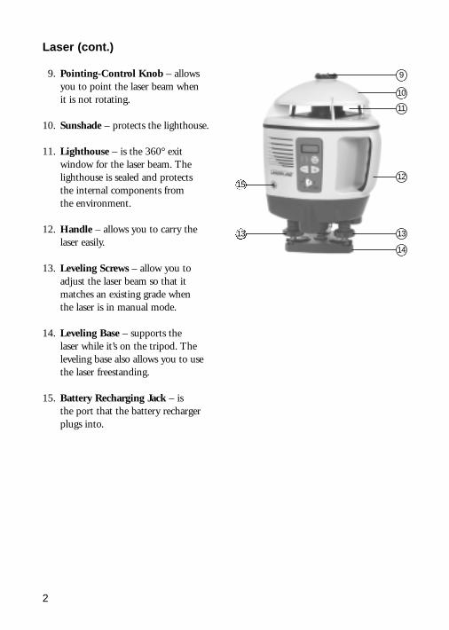
09. Pointing-Control Knob – allowsyou to point the laser beam when it is not rotating.
10. Sunshade – protects the lighthouse.
11. Lighthouse – is the 360° exitwindow for the laser beam. Thelighthouse is sealed and protects the internal components from the environment.
12. Handle – allows you to carry thelaser easily.
13. Leveling Screws – allow you toadjust the laser beam so that itmatches an existing grade when the laser is in manual mode.
14. Leveling Base – supports the laser while it’s on the tripod. Theleveling base also allows you to usethe laser freestanding.
15. Battery Recharging Jack – is the port that the battery rechargerplugs into.
2
9
10
11
12
13
14
15
13
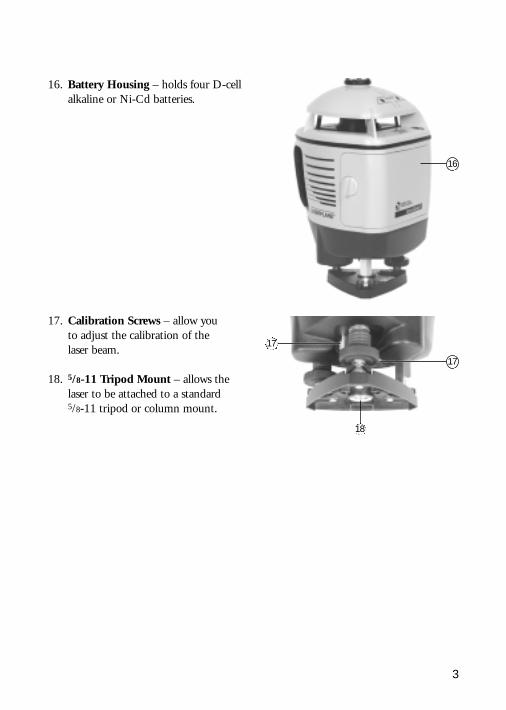
16. Battery Housing – holds four D-cellalkaline or Ni-Cd batteries.
3
16
17. Calibration Screws – allow you to adjust the calibration of the laser beam.
18. 5/8-11 Tripod Mount – allows thelaser to be attached to a standard 5/8-11 tripod or column mount.
18
17
17
4
How to Use the 1242 Laser System
Laser
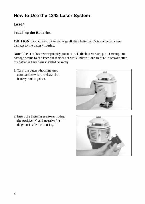
Installing the Batteries
CAUTION: Do not attempt to recharge alkaline batteries. Doing so could causedamage to the battery housing.
Note: The laser has reverse polarity protection. If the batteries are put in wrong, nodamage occurs to the laser but it does not work. Allow it one minute to recover afterthe batteries have been installed correctly.
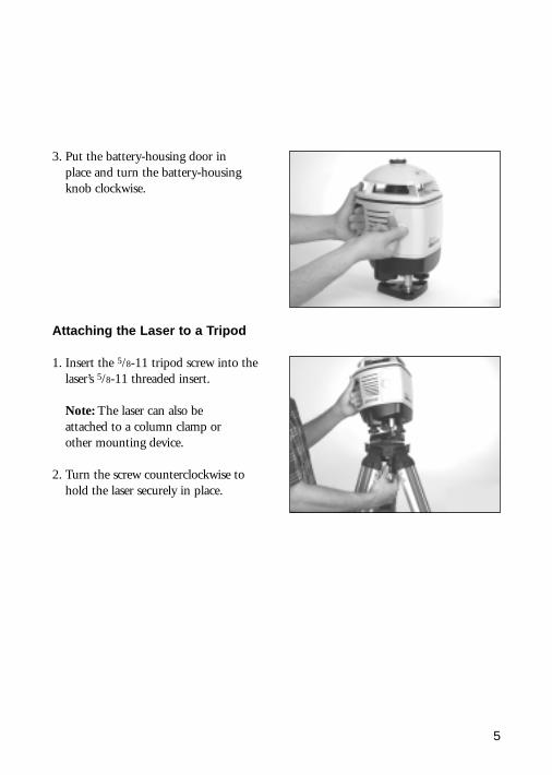
1. Turn the battery-housing knobcounterclockwise to release thebattery-housing door.
2. Insert the batteries as shown notingthe positive (+) and negative (–)diagram inside the housing.
5
Attaching the Laser to a Tripod
1. Insert the 5/8-11 tripod screw into thelaser’s 5/8-11 threaded insert.
Note: The laser can also be attached to a column clamp or other mounting device.
2. Turn the screw counterclockwise tohold the laser securely in place.
3. Put the battery-housing door in place and turn the battery-housingknob clockwise.
6
Setting Up the Laser in Automatic Self-Leveling Mode
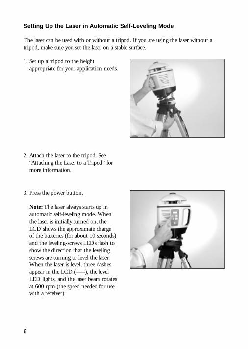
The laser can be used with or without a tripod. If you are using the laser without atripod, make sure you set the laser on a stable surface.
1. Set up a tripod to the heightappropriate for your application needs.
3. Press the power button.
Note: The laser always starts up inautomatic self-leveling mode. Whenthe laser is initially turned on, theLCD shows the approximate charge of the batteries (for about 10 seconds)and the leveling-screws LEDs flash toshow the direction that the levelingscrews are turning to level the laser.When the laser is level, three dashesappear in the LCD (–––), the levelLED lights, and the laser beam rotatesat 600 rpm (the speed needed for usewith a receiver).
2. Attach the laser to the tripod. See“Attaching the Laser to a Tripod” formore information.
7
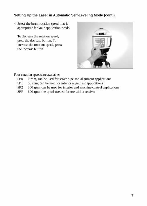
4. Select the beam rotation speed that isappropriate for your application needs.
To decrease the rotation speed, press the decrease button. To increase the rotation speed, press the increase button.
Four rotation speeds are available:SP.0 0 rpm, can be used for sewer pipe and alignment applicationsSP.1 50 rpm, can be used for interior alignment applicationsSP.2 300 rpm, can be used for interior and machine control applicationsSP.F 600 rpm, the speed needed for use with a receiver
Setting Up the Laser in Automatic Self-Leveling Mode (cont.)
8
Setting Up the Laser in Grade Mode
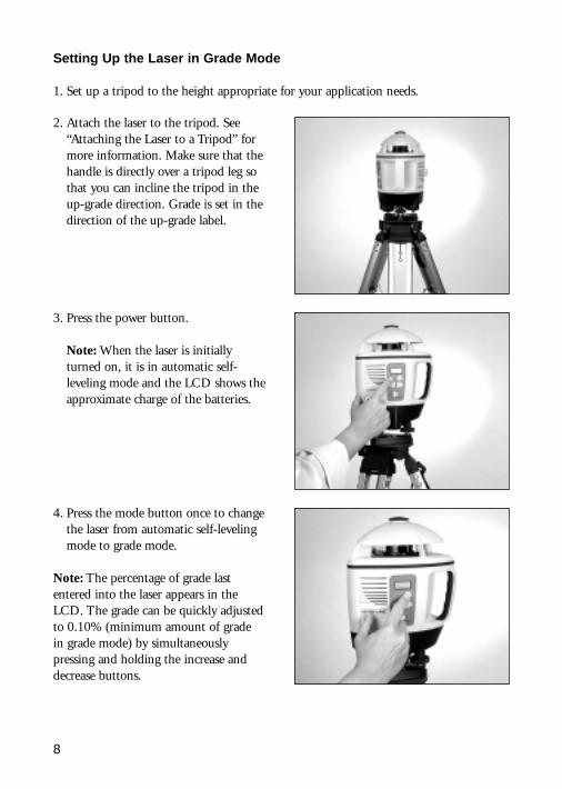
1. Set up a tripod to the height appropriate for your application needs.
2. Attach the laser to the tripod. See“Attaching the Laser to a Tripod” formore information. Make sure that thehandle is directly over a tripod leg sothat you can incline the tripod in theup-grade direction. Grade is set in thedirection of the up-grade label.
3. Press the power button.
Note: When the laser is initiallyturned on, it is in automatic self-leveling mode and the LCD shows theapproximate charge of the batteries.
4. Press the mode button once to changethe laser from automatic self-levelingmode to grade mode.
Note: The percentage of grade lastentered into the laser appears in theLCD. The grade can be quickly adjustedto 0.10% (minimum amount of grade in grade mode) by simultaneouslypressing and holding the increase anddecrease buttons.

9
5. Select the percentage of grade that isappropriate for your application needs.To decrease the percentage of grade,press and hold the decrease button. To increase the percentage of grade,press and hold the increase button.When the desired grade appears in theLCD, the laser automatically adjuststo the grade shown.
Note: If the leveling screws LEDscontinue to flash after the laser hastried to self level, the laser is beyondits self-leveling range. To get the laserwithin its self-leveling range, turn theleveling screws in the direction shownby the leveling screws LEDs or inclinethe tripod in the up-grade position.
Note: For grades between 10% and25% (maximum amount in grademode), incline the tripod in the up-grade direction.
Note: When the laser is in grademode, the beam’s rotation speed is 600 rpm.
Setting Up the Laser in Grade Mode (cont.)
10
Setting Up the Laser in Manual Mode
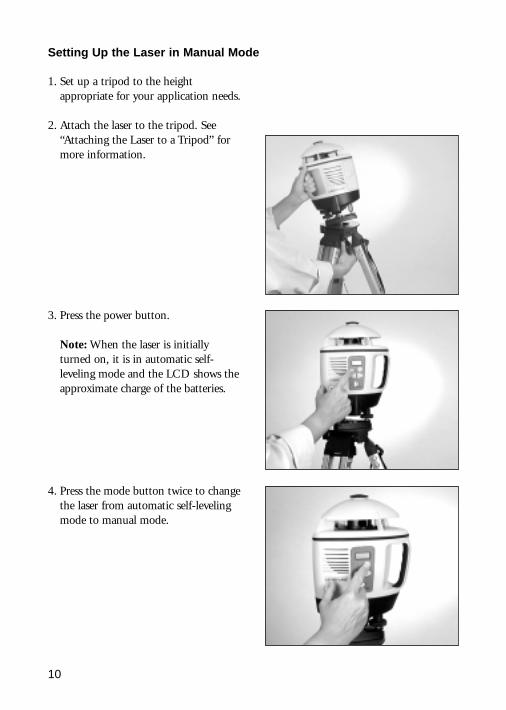
1. Set up a tripod to the heightappropriate for your application needs.
2. Attach the laser to the tripod. See“Attaching the Laser to a Tripod” formore information.
3. Press the power button.
Note: When the laser is initiallyturned on, it is in automatic self-leveling mode and the LCD shows theapproximate charge of the batteries.
4. Press the mode button twice to changethe laser from automatic self-levelingmode to manual mode.
11
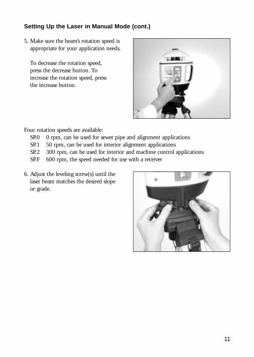
5. Make sure the beam’s rotation speed isappropriate for your application needs.
To decrease the rotation speed, press the decrease button. To increase the rotation speed, press the increase button.
Four rotation speeds are available:SP.0 0 rpm, can be used for sewer pipe and alignment applicationsSP.1 50 rpm, can be used for interior alignment applicationsSP.2 300 rpm, can be used for interior and machine control applicationsSP.F 600 rpm, the speed needed for use with a receiver
6. Adjust the leveling screw(s) until thelaser beam matches the desired slopeor grade.
Setting Up the Laser in Manual Mode (cont.)
12
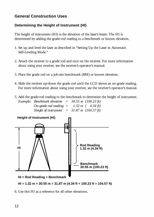
General Construction Uses
Determining the Height of Instrument (HI)
The height of instrument (HI) is the elevation of the laser’s beam. The HI isdetermined by adding the grade-rod reading to a benchmark or known elevation.
1. Set up and level the laser as described in “Setting Up the Laser in Automatic Self-Leveling Mode.”
2. Attach the receiver to a grade rod and turn on the receiver. For more informationabout using your receiver, see the receiver’s operator’s manual.
3. Place the grade rod on a job-site benchmark (BM) or known elevation.
4. Slide the receiver up/down the grade rod until the LCD shows an on-grade reading.For more information about using your receiver, see the receiver’s operator’s manual.
5. Add the grade-rod reading to the benchmark to determine the height of instrument.Example: Benchmark elevation = 30.55 m (100.23 ft)
On-grade rod reading = 1.32 m (004.34 ft)Height of instrument = 31.87 m (104.57 ft)
HIRod Reading1.32 m (4.34 ft)
Benchmark30.55 m (100.23 ft)
HI = Rod Reading + Benchmark
HI = 1.32 m + 30.55 m = 31.87 m (4.34 ft + 100.23 ft = 104.57 ft)
Height of Instrument (HI)
6. Use this HI as a reference for all other elevations.
13
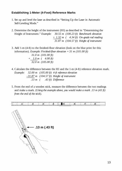
Establishing 1-Meter (4-Foot) Reference Marks
1. Set up and level the laser as described in “Setting Up the Laser in Automatic Self-Leveling Mode.”
2. Determine the height of the instrument (HI) as described in “Determining theHeight of Instrument.” Example: 30.55 m (100.23 ft) Benchmark elevation
+01.32 m (004.34 ft) On-grade rod reading31.87 m (104.57 ft) Height of instrument
3. Add 1-m (4-ft) to the finished-floor elevation (look on the blue print for thisinformation). Example: Finished-floor elevation = 31 m (101.00 ft)
31.0 m (101.00 ft)+001.0 m (004.00 ft)
32.0 m (105.00 ft)
4. Calculate the difference between the HI and the 1-m (4-ft) reference elevation mark.Example: 32.00 m (105.00 ft) 4-ft reference elevation
–31.87 m (104.57 ft) Height of instrument.13 m (000.43 ft) Difference
5. From the end of a wooden stick, measure the difference between the two readingsand make a mark. (Using the example above, you would make a mark .13 m (43 ft)from the end of the stick).
.1 .2 .4.3 .5 .6 .8.7.1
.2
.4
.3
.5
.13 m (.43 ft)
14
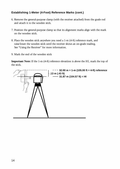
.13 m (.43 ft) 32.00 m = 1-m (105.00 ft = 4-ft) reference
31.87 m (104.57 ft) = HI
Establishing 1-Meter (4-Foot) Reference Marks (cont.)
6. Remove the general-purpose clamp (with the receiver attached) from the grade rodand attach it to the wooden stick.
7. Position the general-purpose clamp so that its alignment marks align with the markon the wooden stick.
8. Place the wooden stick anywhere you need a 1-m (4-ft) reference mark, andraise/lower the wooden stick until the receiver shows an on-grade reading. See “Using the Receiver” for more information.
9. Mark the end of the wooden stick
Important Note: If the 1-m (4-ft) reference elevatiion is above the HI, mark the top ofthe stick.
15
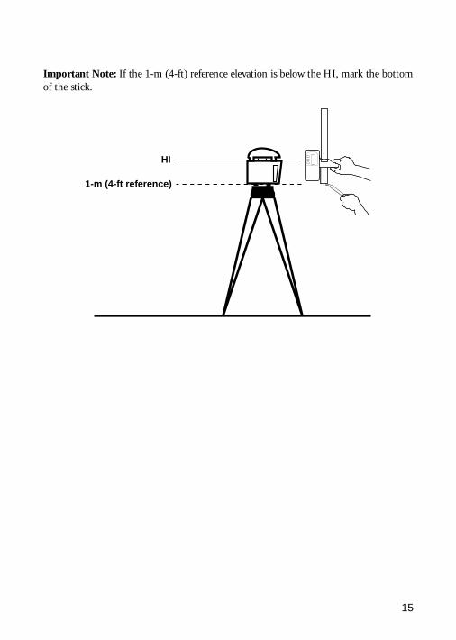
Important Note: If the 1-m (4-ft) reference elevation is below the HI, mark the bottomof the stick.
1-m (4-ft reference)
HI

16
Determining the Difference in Elevation
1. Set up and level the laser as described in “Setting Up the Laser in Automatic Self-Leveling Mode.”
2. Determine the height of the instrument (HI) as described in “Determining theHeight of Instrument.”
3. Place the grade rod on the point where you need an elevation reading.
4. Slide the receiver up/down the grade rod until the LCD shows an on-grade reading(rod reading A). For more information about using your receiver, see the receiver’soperator’s manual.
5. Calculate the difference between the HI and rod reading A. See the illustration belowfor more information.
6. Place the grade rod on another point where you need an elevation reading.
7. Slide the receiver up/down the grade rod until the LCD shows an on-grade reading(rod reading B).
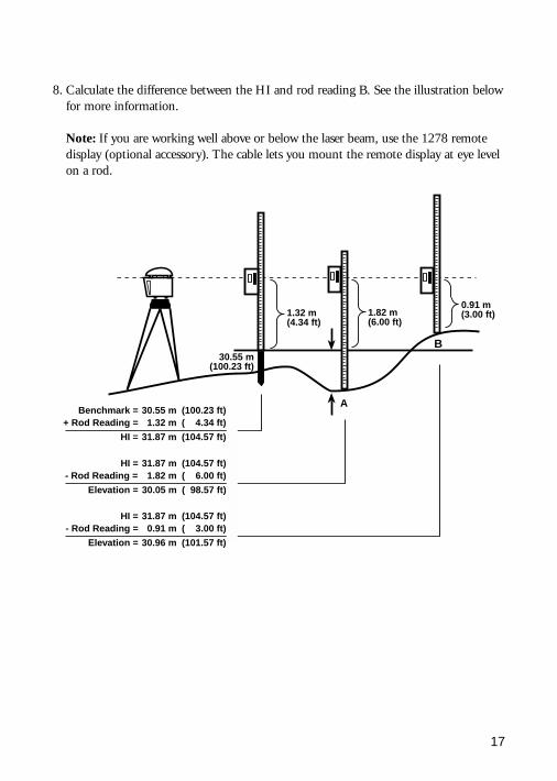
17
0.91 m(3.00 ft)1.32 m
(4.34 ft)1.82 m(6.00 ft)
B
A
30.55 m(100.23 ft)
Benchmark =+ Rod Reading =
HI =
HI =- Rod Reading =
Elevation =
HI =- Rod Reading =
Elevation =
30.55 m1.32 m
31.87 m
31.87 m1.82 m
30.05 m
31.87 m0.91 m
30.96 m
(100.23 ft)(004.34 ft)
(104.57 ft)
(104.57 ft)(006.00 ft)
(098.57 ft)
(104.57 ft)(003.00 ft)
(101.57 ft)
8. Calculate the difference between the HI and rod reading B. See the illustration belowfor more information.
Note: If you are working well above or below the laser beam, use the 1278 remotedisplay (optional accessory). The cable lets you mount the remote display at eye levelon a rod.
18
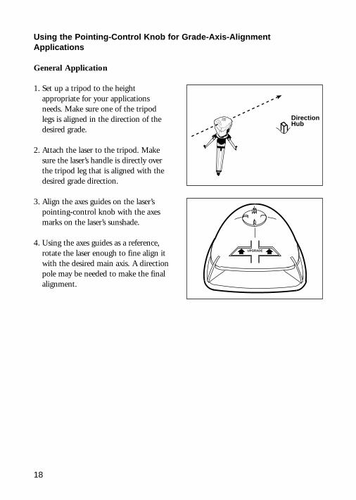
1. Set up a tripod to the heightappropriate for your applicationsneeds. Make sure one of the tripodlegs is aligned in the direction of thedesired grade.
2. Attach the laser to the tripod. Makesure the laser’s handle is directly overthe tripod leg that is aligned with thedesired grade direction.
3. Align the axes guides on the laser’spointing-control knob with the axesmarks on the laser’s sunshade.
4. Using the axes guides as a reference,rotate the laser enough to fine align itwith the desired main axis. A directionpole may be needed to make the finalalignment.
Using the Pointing-Control Knob for Grade-Axis-AlignmentApplications
General Application
UPGRADE
DirectionHub
19
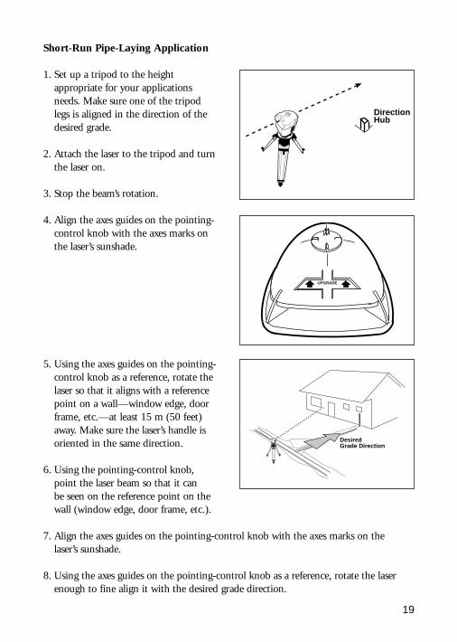
Short-Run Pipe-Laying Application
1. Set up a tripod to the heightappropriate for your applicationsneeds. Make sure one of the tripodlegs is aligned in the direction of thedesired grade.
2. Attach the laser to the tripod and turn the laser on.
3. Stop the beam’s rotation.
4. Align the axes guides on the pointing-control knob with the axes marks onthe laser’s sunshade.
5. Using the axes guides on the pointing-control knob as a reference, rotate thelaser so that it aligns with a referencepoint on a wall—window edge, doorframe, etc.—at least 15 m (50 feet)away. Make sure the laser’s handle isoriented in the same direction.
6. Using the pointing-control knob, point the laser beam so that it can be seen on the reference point on the wall (window edge, door frame, etc.).
7. Align the axes guides on the pointing-control knob with the axes marks on the laser’s sunshade.
8. Using the axes guides on the pointing-control knob as a reference, rotate the laserenough to fine align it with the desired grade direction.
UPGRADE
DirectionHub
DesiredGrade Direction
20
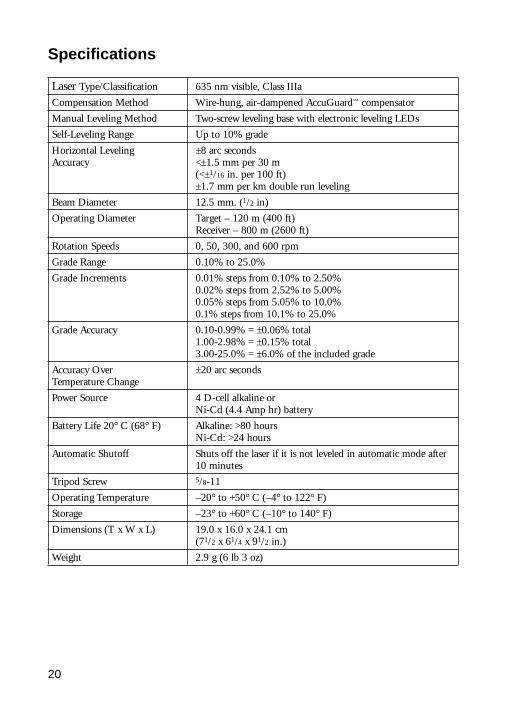
Specifications
Laser Type/Classification 635 nm visible, Class IIIa
Compensation Method Wire-hung, air-dampened AccuGuard™ compensator
Manual Leveling Method Two-screw leveling base with electronic leveling LEDs
Self-Leveling Range Up to 10% grade
Horizontal Leveling ±8 arc secondsAccuracy <±1.5 mm per 30 m
(<±1/16 in. per 100 ft)±1.7 mm per km double run leveling
Beam Diameter 12.5 mm. (1/2 in)
Operating Diameter Target – 120 m (400 ft)Receiver – 800 m (2600 ft)
Rotation Speeds 0, 50, 300, and 600 rpm
Grade Range 0.10% to 25.0%
Grade Increments 0.01% steps from 0.10% to 2.50%0.02% steps from 2.52% to 5.00%0.05% steps from 5.05% to 10.0%0.1% steps from 10.1% to 25.0%
Grade Accuracy 0.10-0.99% = ±0.06% total1.00-2.98% = ±0.15% total3.00-25.0% = ±6.0% of the included grade
Accuracy Over ±20 arc secondsTemperature Change
Power Source 4 D-cell alkaline or Ni-Cd (4.4 Amp hr) battery
Battery Life 20° C (68° F) Alkaline: >80 hoursNi-Cd: >24 hours
Automatic Shutoff Shuts off the laser if it is not leveled in automatic mode after10 minutes
Tripod Screw 5/8-11
Operating Temperature –20° to +50° C (–4° to 122° F)
Storage –23° to +60° C (–10° to 140° F)
Dimensions (T x W x L) 19.0 x 16.0 x 24.1 cm(71/2 x 61/4 x 91/2 in.)
Weight 2.9 g (6 lb 3 oz)

21
Maintenance and Care
You will get years of service from the leveling system by following the maintenance and care recommendations in this manual. Carry the laser in its moisture-resistant,field-tested carrying case to safely move the laser from one job to another.
However well the product is designed, mishaps do occur. The most common problemsassociated with these are covered in the following areas.
Storage
CAUTION: Do not store the laser in a wet carrying case. If the case gets wet, open itand let it dry before storing the laser.
Battery Disposal
Some states and local areas have regulations regarding the disposal of rechargeablebatteries. Be sure that replaced batteries are disposed of properly.
System Cleaning
Use only a good-quality glass cleaner and a soft cloth to clean all external opticalcomponents. A dry cloth used on the laser exit windows, LaserEye receiving window, or displays could scratch or damage these surfaces.
Monthly, wipe off with a moist, clean cloth any dust or dirt from the laser’s outersurface, inside the battery housing, and within the leveling base. Blow off any loosedebris before cleaning any surfaces to prevent scratching of optical surfaces.
22
Troubleshooting
If none of the following techniques corrects the problem, take your system to a localTrimble dealer or authorized service center for evaluation or repair.
Problem Solution
Laser will not operate • Press power button.• Check or replace batteries.• Return laser to service center for inspection.
Laser out-of-level indicator • Make sure the laser is mounted to a stable surface.does not shut off • Press mode button so that the laser is in automatic self-leveling
or grade mode.• Make sure the leveling screws are free to turn.• Allow the laser to re-level.• Return laser to service center for inspection.
SafeGuard LED is on • Check and adjust laser plane calibration as necessary.• Return laser to service center for inspection.
Laser plane not accurate • Check and adjust laser plane calibration as needed.• Return laser to service center for inspection.
23
Calibration
As with any precision instrument, the calibration needs checking on a regular basis(such as the beginning of each job, or if the laser has been handled roughly). If the laseris to be used below freezing, be sure to check calibration under those conditions.
The laser has a calibration error when the laser plane coming out one side of the laser is above true level, and the laser plane coming out the opposite side is below true level.Adjusting the position of the laser plane requires making minor adjustments to the axis-calibration screws found immediately above the laser’s leveling screws.
When the laser is properly calibrated, it emits a 360° horizontal level plane so that if the laser is turned 180° or 90° from its original position, the reading is within ±3.0 mm/30 m (±1/8 in. per 100 ft) of the original position.
To check the horizontal calibration, you’ll need a tripod with a 5/8-11 threaded mount,receiver, and 1.5 mm (1/16 in.) diameter pin or small nail. If you need to adjust thecalibration, having another person to help saves time.
} ±1.5 mm(±1/16 inch)
30 m (100 ft)
True Level
Calibration Error
24
Calibration (cont.)
1. Set up and level the laser 30 m (100 ft) from a wall.
2. Raise/lower the receiver until you get an on-grade reading for the +Y axis. Using theon-grade marking notch as a reference, make a mark on the wall.
Note: For increased precision, use the fine-sensitivity setting (±1.5 mm/±1/16 in.) onthe receiver.
30 m (100 ft)
+Y
30 m (100 ft)
+Y
Y1
25
3. Rotate the laser 180° (–Y axis toward the wall) and re-level the laser.
4. Raise/lower the receiver until you get an on-grade reading for the –Y axis. Using theon-grade marking notch as a reference, make a mark on the wall.
5. Measure the difference between the two marks. If they differ more than 3 mm (1/8 in.), the laser needs calibrating.
30 m (100 ft)
-Y
30 m (100 ft)
-Y
Y2
26
Calibration (cont.)
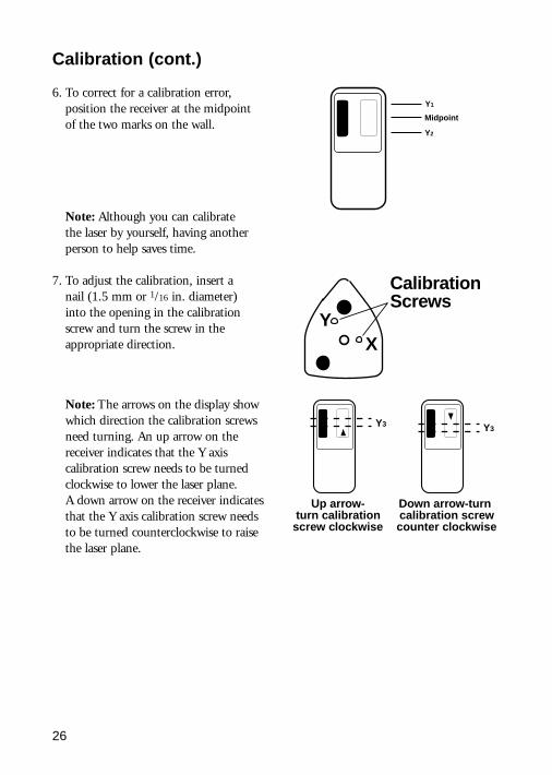
6. To correct for a calibration error,position the receiver at the midpointof the two marks on the wall.
Note: Although you can calibrate the laser by yourself, having anotherperson to help saves time.
7. To adjust the calibration, insert a nail (1.5 mm or 1/16 in. diameter) into the opening in the calibrationscrew and turn the screw in theappropriate direction.
YX
CalibrationScrews
Up arrow-turn calibration
screw clockwise
Down arrow-turncalibration screwcounter clockwise
Y3Y3
Note: The arrows on the display showwhich direction the calibration screwsneed turning. An up arrow on thereceiver indicates that the Y axiscalibration screw needs to be turnedclockwise to lower the laser plane. A down arrow on the receiver indicatesthat the Y axis calibration screw needsto be turned counterclockwise to raisethe laser plane.
Y2
Y1
Midpoint
27
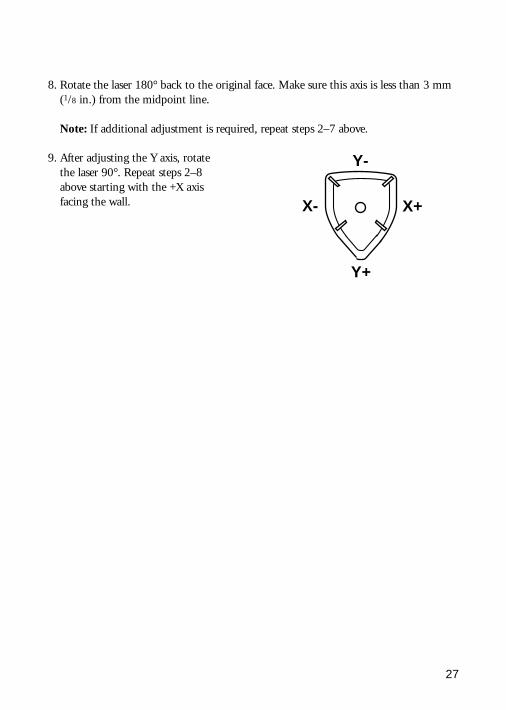
8. Rotate the laser 180° back to the original face. Make sure this axis is less than 3 mm(1/8 in.) from the midpoint line.
Note: If additional adjustment is required, repeat steps 2–7 above.
Y-
Y+
X- X+
9. After adjusting the Y axis, rotate the laser 90°. Repeat steps 2–8 above starting with the +X axis facing the wall.

28
Service
Our goal is to provide prompt and efficient service through competent service dealers.To locate your local dealer or authorized Trimble Service Center, contact one of ouroffices our listed below.
North AmericaTrimble Engineering andConstruction Division
5475 Kellenburger RoadDayton, Ohio 45424-1099
U.S.A.(800) 538-7800
(Toll Free in U.S.A.)+1-937-233-8921 Phone
+1-937-233-9004 Faxwww.trimble.com
Africa & Middle EastTrimble Navigation Limited
P.O. Box 17760Jebel Ali Free Zone, Dubai
UAE+971-4-881-3005 Phone
+971-4-881-3307 Fax
EuropeTrimble GmbH
Am Prime Parc 1165479 Raunheim
GERMANY+49-61422-1000 Phone+49-6142-2100-550 Fax
Asia-PacificTrimble Navigation
Australia Pty LimitedLevel 1/123 Gotha Street
Fortitude Valley, QLD 4006AUSTRALIA
+61-7-3216-0044 Phone+61-7-3216-0088 Fax
Latin AmericaTrimble Navigation Limited
6505 Blue Lagoon DriveSuite 120
Miami, FL 33126U.S.A.
+1-305-263-9033 Phone+1-305-263-8975 Fax
ChinaTrimble Export Limited
Representative OfficeSuite 16D, Building 2
Epoch Center4 Beiwa Road, Haidian District
Beijing 100089P.R. CHINA
+86-10-6847-7756 Phone+86-10-6847-7786 Fax

29
Before returning your system for repair, be sure to do the following:1. Put a note into the package identifying yourself as the owner. 2. Explain the operating difficulty.3. Include a return address and phone number.4. If the laser is in warranty, provide verification of the date of purchase.5. Pack the equipment securely for shipment in its original carrying case.6. Return the equipment prepaid and insured to your local dealer or authorized
Trimble Service Center.7. Request estimate of charges for non-warranty or other service work before repair
begins. If estimates are not requested, repair work will begin immediately.
All certified outlets have factory-trained personnel and use authorized replacement partsto ensure proper and quick return. For long-distance shipments, UPS, 2nd-Day Air, orair freight is recommended.
Except for one-way transportation charges, there will be no charge for repairs caused byproblems due to defective materials and/or workmanship under warranty.
30
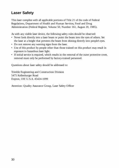
Laser Safety
This laser complies with all applicable portions of Title 21 of the code of FederalRegulations, Department of Health and Human Services, Food and DrugAdministration (Federal Register, Volume 50, Number 161, August 20, 1985).
As with any visible laser device, the following safety rules should be observed:• Never look directly into a laser beam or point the beam into the eyes of others. Set
the laser at a height that prevents the beam from shining directly into people’s eyes.• Do not remove any warning signs from the laser.• Use of this product by people other than those trained on this product may result in
exposure to hazardous laser light.• If initial service is required, which results in the removal of the outer protective cover,
removal must only be performed by factory-trained personnel.
Questions about laser safety should be addressed to:
Trimble Engineering and Construction Division5475 Kellenburger RoadDayton, OH U.S.A. 45424-1099
Attention: Quality Assurance Group, Laser Safety Officer
31
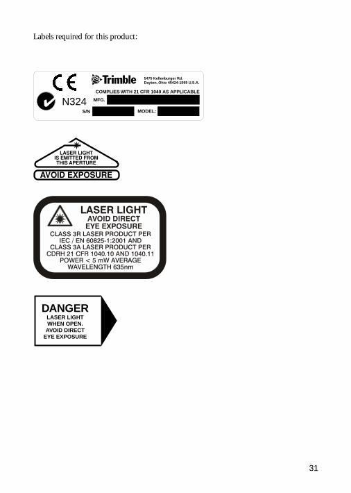
Labels required for this product:
5475 Kellenburger Rd.Dayton, Ohio 45424-1099 U.S.A.
MFG.
S/N MODEL:
✔ N324COMPLIES WITH 21 CFR 1040 AS APPLICABLE
DANGERLASER LIGHTWHEN OPEN.
AVOID DIRECTEYE EXPOSURE

32
EMC Declaration of Conformity
This laser has been tested and found to comply with the limits for a Class B digitaldevice for radio noise for digital apparatus set out in the Radio Interference Regulationsof the Canadian Department of Communication, and is pursuant to part 15 of theFederal Communication Commission (FCC) rules. These limits are designed to providereasonable protection against harmful interference in a residential installation. This lasergenerates radio frequency. If it’s not used in accordance with the instructions, it maycause harmful interference to radio or television reception. Such interference can bedetermined by turning the laser off and on. You are encouraged to try eliminating theinterference by one or more of the following measures:
• Reorient or relocate the receiving antenna.• Increase the separation between the laser and the receiver.
For more information, consult your dealer or an experienced radio/television technician.
CAUTION: Changes or modifications to the laser that are not expressly approved bySpectra Precision could void authority to use the equipment.
Application of Council Directive(s): 89/336/EEC
Manufacturer’s Name: Trimble
Manufacturer’s Address: 5475 Kellenburger RoadDayton, Ohio 45424-1099 U.S.A.
European Representative Address: Trimble Engineering and Construction GmbHAm Prime Parc 11Siemensstrasse 20 D-64289Darmstadt, Germany
Model Number(s): 1242
Conformance to Directive(s): EC Directive 89/336/EEC using EN55022 and EN50082-1
Equipment Type/Environment: ITE/residential, commercial & light industrial
Product Standards: Product meets the limit B and methods ofEN55022Product meets the levels and methods of IEC 801-2, 8 kV air, 4 kV contact, IEC 801-3, 3 V/m 26 to 1000 MHz 80%, @ 1 kHzIEC 801-4, ac leads 2 kV

33
Warranty
Trimble warrants the 1242 laser and receiver to be free of defects in material andworkmanship for a period of two years. This warranty period is in effect from the date the system is delivered by Trimble or its authorized Dealer to the purchaser, or is put into service by a Dealer as a demonstrator or rental components.
Additionally, items covered by the standard Trimble one-year warranty are theaccessories. All other components not manufactured by Trimble but sold as a part of the system such as tripods and grade rods, will carry a 90-day warranty or themanufacturer’s warranty, whichever is greater.
Trimble or its Authorized Service Center will repair or replace, at its option, anydefective part of components of which notice has been given during the warrantyperiod. A Warranty Registration Card must be filled out properly and on file withTrimble Service Department before warranty repair or replacement can be approved.Travel and per diem expenses, if required, to and from the place where repairs are made will be charged to the purchaser at the prevailing rates.
Customers should send products to the nearest Authorized Factory Service Center forwarranty repairs, freight prepaid. In countries with Trimble Subsidiary Service Centers,the repaired products will be returned to the customer, freight prepaid.
Any evidence of negligent, abnormal use, accident, or any attempt to repair equipmentby other than factory-authorized personnel using Trimble certified or recommendedparts, automatically voids the warranty.
Special precautions have been taken to ensure the calibration of the laser; however,calibration is not covered by this warranty. Maintenance of the calibration is theresponsibility of the user.
The foregoing states the entire liability of Trimble regarding the purchase and use of itsequipment. Trimble will not be held responsible for any consequential loss or damage ofany kind.
This warranty is in lieu of all other warranties, except as set forth above, including an implied warranty mechantability of fitness for a particular purpose, are herebydisclaimed. This warranty is in lieu of all other warranties, expressed or implied.

34
Notes

35
Notes

36
Notes

37N324
Trimble Engineering and Construction Division5475 Kellenurger RoadDayton, Ohio 45424-1099U.S.A.+1-937-233-8921 Phone
www.trimble.com© 2002, Trimble Navigation Limited. All rights reserved.
Reorder PN 1242-0100 Rev B. (06/02)