12682 03 ir 550 a e
TRANSCRIPT
ERSA GmbH Soldering Tools & Inspection Systems
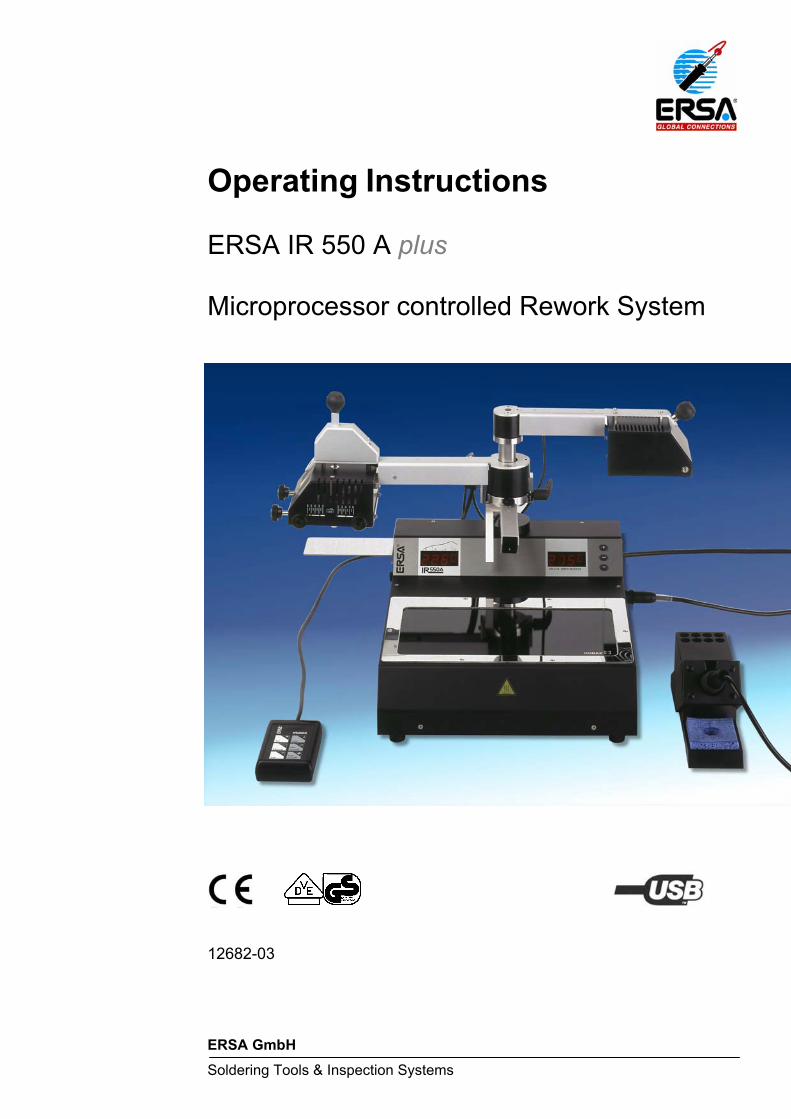
Operating Instructions ERSA IR 550 A plus
Microprocessor controlled Rework System
12682-03
ERSA IR 550 A Operating instructions
ERSA GmbH 16.02.05 FE.no 12682_03 IR 550 A_e.doc - 2/33 -
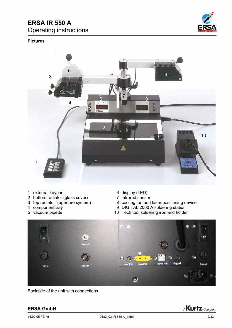
Pictures
1 external keypad 6 display (LED) 2 bottom radiator (glass cover) 7 infrared sensor 3 top radiator (aperture system) 8 cooling fan and laser positioning device 4 component tray 9 DIGITAL 2000 A soldering station 5 vacuum pipette 10 Tech tool soldering iron and holder
Backside of the unit with connections
3
1
2
8
94
5
7
10
6
ERSA IR 550 A Operating instructions
ERSA GmbH 16.02.05 FE.no 12682_03 IR 550 A_e.doc - 3/33 -
We appreciate your decision to purchase our high-quality ERSA IR 550 A Rework System. This device has been manufactured according to highest quality standards and was tested thoroughly before shipment. It is very easy in operation, nevertheless we suggest to read this manual before operating the system. If you have any additional questions to your equipment, please do not hesitate to contact us at: ERSA GmbH Leonhard-Karl-Str. 24 97877 Wertheim Germany Tel.: +49 (0) 93 42 800-0 Fax: +49 (0) 93 42 800-100 Email: [email protected] Web: www.ersa.com

ERSA IR 550 A Operating instructions
ERSA GmbH 16.02.05 FE.no 12682_03 IR 550 A_e.doc - 4/33 -
TABLE OF CONTENTS Page 1 Introduction................................................................................................................................ 5 2 Technical Data........................................................................................................................... 6 3 Safety instructions ..................................................................................................................... 7 4 Commissioning.......................................................................................................................... 8
4.1 Before commissioning ....................................................................................................... 8 4.2 First start-up ...................................................................................................................... 9
4.2.1 Setting up................................................................................................................... 9 4.2.2 Electrical connections .............................................................................................. 11 4.2.3 Switching on ............................................................................................................ 11
4.3 Tips for the SMT Rework Process................................................................................... 12
5 Functional description.............................................................................................................. 13 5.1 Functional elements of IR 550 A ..................................................................................... 13
5.1.1 Infrared radiators ..................................................................................................... 13 5.1.2 Temperature sensors............................................................................................... 13 5.1.3 Cooling fan and laser positioning device ................................................................ 14 5.1.4 Vacuum pipette and vacuum pump ......................................................................... 14 5.1.5 DIGITAL 2000 A soldering station ........................................................................... 14 5.1.6 Serial port, documentation software IRSoft ............................................................. 14
5.2 Operation and program parameters ................................................................................ 15 5.2.1 Menus and programs............................................................................................... 15 5.2.2 Parameter setting and description ........................................................................... 17 5.2.3 Operating process „soldering“ ................................................................................. 22 5.2.4 Operating process „desoldering“ ............................................................................. 23 5.2.5 Factory settings ....................................................................................................... 23
6 Error diagnosis and repair ....................................................................................................... 24 7 Maintenance............................................................................................................................ 26 8 Spare parts and options .......................................................................................................... 27 9 Appendix.................................................................................................................................. 29 10 Index........................................................................................................................................ 32 11 Warranty .................................................................................................................................. 33
ERSA IR 550 A Operating instructions
ERSA GmbH 16.02.05 FE.no 12682_03 IR 550 A_e.doc - 5/33 -
1 Introduction We appreciate your decision to purchase an ERSA IR 550 A Rework System. With this microprocessor unit which is also equipped with powerful infrared- an sensor technique ERSA provides a rework soldering system to meet the highest requirements of modern industrial electronic production. Selective soldering processes during rework of surface mounted devices are the main fields of application of this valuable soldering system. The unique IR-radiator technique by ERSA has been optimised within the IR 550 A. The programmable temperature control allows reproducible soldering results for nearly every application. At any time, the soldering process is monitored by a non contacting infrared sensor and grants for optimal process control. Additionally, the IR 550 A provides an active cooling of the PCB. The integrated soldering station DIGITAL 2000 A completes the IR 550 A to a modern and flexible tool for any professional user. The combination of IR 550 A with the Reflow Process Camera RPC 550 A or the Precision-Placement System PL 550 A creates a high-end workplace for modern rework in electronic production.
ERSA IR 550 A Operating instructions
ERSA GmbH 16.02.05 FE.no 12682_03 IR 550 A_e.doc - 6/33 -
2 Technical Data IR 550 A main unit: Rating IR-top radiator 4 x 200 W (size 60 x 60 mm) Rating IR-bottom radiator 2 x 400 W (size 135 x 250 mm) max. power consumption 1600 W Wavelength of IR radiators 2 - 5 µm Voltage 230 V ~, 50 Hz or 115 V, 60 Hz Fuse 10 A (slow blow) Design Safety category 1 Operation external Keypad Interface Universal Serial Bus (USB) Display integrated LED display Power cord approx. 2 m Weight approx. 9.75 kg Warm-up time bottom radiator 90 s Heat up rate during process 0.3 to 2 K/s Dimensions 300 x 380 mm (B x T) Height 315 mm max. travel (z-axis) 50 mm Distance to top radiator (non-contacting sensor) 40 mm max. working depth approx. 170 mm Airflow cooling fan 72 m3/h For technical data of DIGITAL 2000 A soldering station, please refer to the included operating instructions „ERSA DIGITAL 2000 A“. (3BA00044)
ERSA IR 550 A Operating instructions
ERSA GmbH 16.02.05 FE.no 12682_03 IR 550 A_e.doc - 7/33 -
3 Safety instructions Note: Before commissioning, please refer to the included safety instructions. Please note that this product has been designed for the soldering and desoldering of electronic components only!
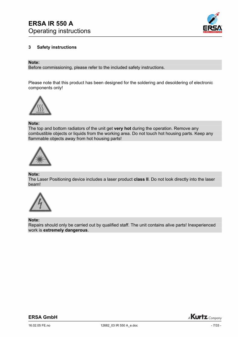
Note: The top and bottom radiators of the unit get very hot during the operation. Remove any combustible objects or liquids from the working area. Do not touch hot housing parts. Keep any flammable objects away from hot housing parts!
Note: The Laser Positioning device includes a laser product class II. Do not look directly into the laser beam!
Note: Repairs should only be carried out by qualified staff. The unit contains alive parts! Inexperienced work is extremely dangerous.

ERSA IR 550 A Operating instructions
ERSA GmbH 16.02.05 FE.no 12682_03 IR 550 A_e.doc - 8/33 -
4 Commissioning 4.1 Before commissioning Please check that all components listed below are complete and undamaged:
• IR 550 A basic unit with integrated DIGITAL 2000 A soldering station • External keypad with connection cord • Power cord • Spare silicone cup ∅ 5 mm, Spare silicone cup ∅ 8 mm • Tech tool soldering iron • Holder for soldering tool • External K-Type thermocouple • Stainless steel grid (for intensive bottom heating) • USB cable for connection to a PC • PC-Software IRSoft* on CD-Rom • IR 550 A operating instructions on CD-Rom • DIGITAL 2000 A operating instructions (3BA00044) • Safety instructions
* Current updated software is available at ERSA GmbH or on www.ersa.com . Should the above components be damaged or incomplete, please contact your supplier.
Attention: The top and bottom radiators of the unit get very hot during operating the system. Remove any combustible objects or liquids from the working area. Keep any flammable objects away from hot housing parts!
ERSA IR 550 A Operating instructions
ERSA GmbH 16.02.05 FE.no 12682_03 IR 550 A_e.doc - 9/33 -
4.2 First start-up Please read through the operating instructions completely before commissioning. Procedure for commissioning: 4.2.1 Setting up
• Unpack the IR 550 A unit. • Put the unit onto a plane, solid workbench. • Swing both arms into their rear end position. They will snap in there. • Vertical adjustment of top radiator and infrared sensor
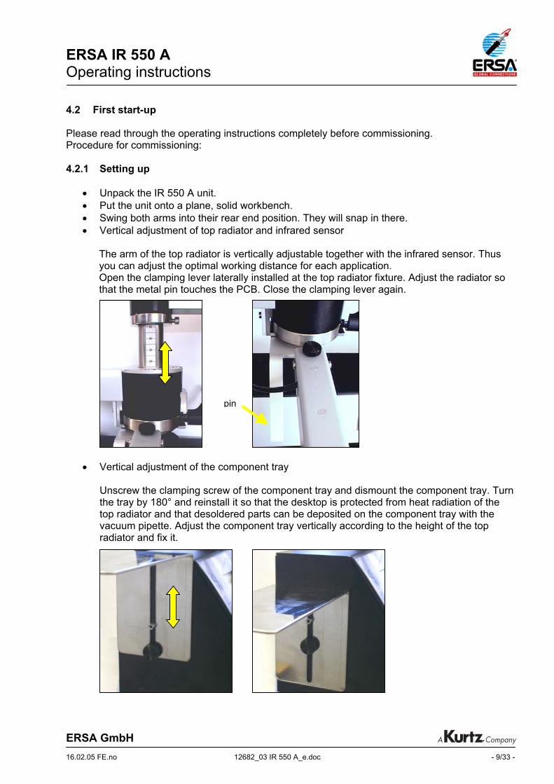
The arm of the top radiator is vertically adjustable together with the infrared sensor. Thus you can adjust the optimal working distance for each application. Open the clamping lever laterally installed at the top radiator fixture. Adjust the radiator so that the metal pin touches the PCB. Close the clamping lever again.
• Vertical adjustment of the component tray Unscrew the clamping screw of the component tray and dismount the component tray. Turn the tray by 180° and reinstall it so that the desktop is protected from heat radiation of the top radiator and that desoldered parts can be deposited on the component tray with the vacuum pipette. Adjust the component tray vertically according to the height of the top radiator and fix it.
pin
ERSA IR 550 A Operating instructions
ERSA GmbH 16.02.05 FE.no 12682_03 IR 550 A_e.doc - 10/33 -
• Aperture adjustment
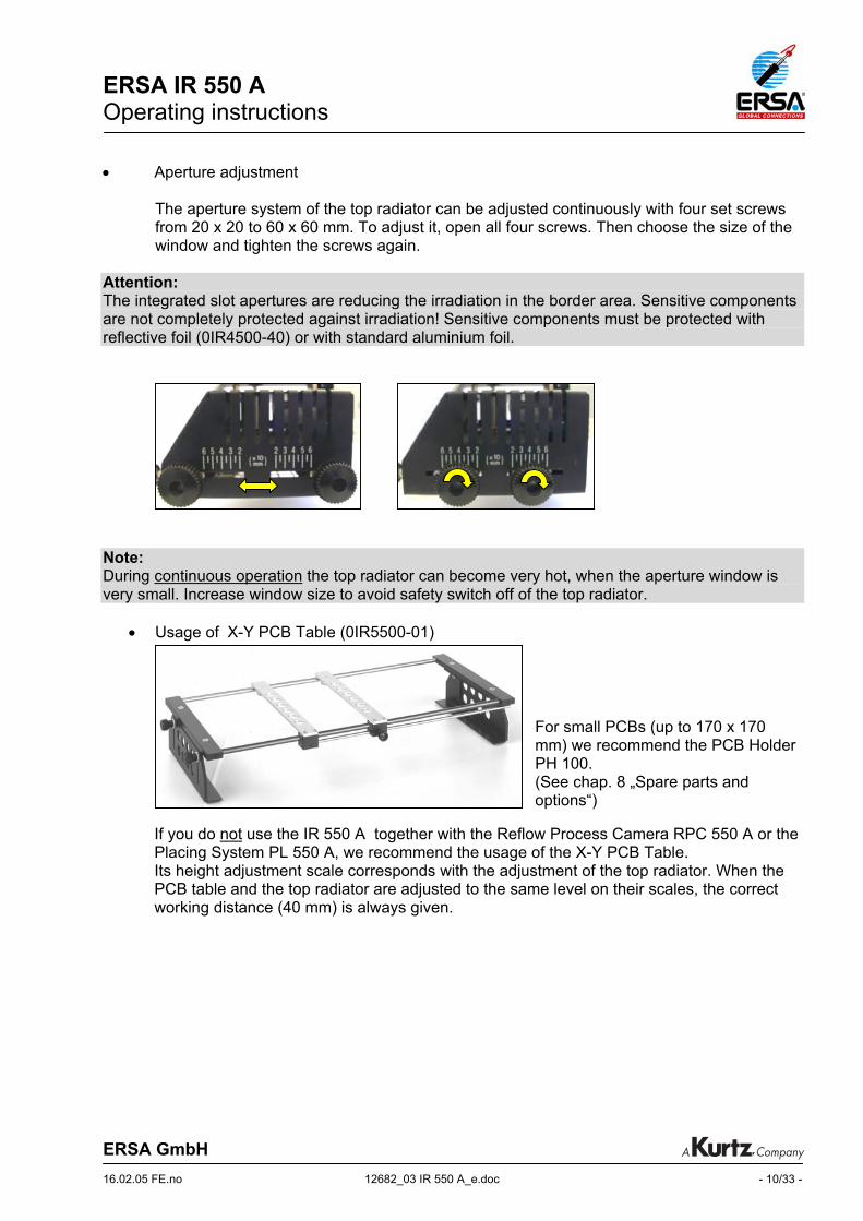
The aperture system of the top radiator can be adjusted continuously with four set screws from 20 x 20 to 60 x 60 mm. To adjust it, open all four screws. Then choose the size of the window and tighten the screws again.
Attention: The integrated slot apertures are reducing the irradiation in the border area. Sensitive components are not completely protected against irradiation! Sensitive components must be protected with reflective foil (0IR4500-40) or with standard aluminium foil. Note: During continuous operation the top radiator can become very hot, when the aperture window is very small. Increase window size to avoid safety switch off of the top radiator.
• Usage of X-Y PCB Table (0IR5500-01)
If you do not use the IR 550 A together with the Reflow Process Camera RPC 550 A or the Placing System PL 550 A, we recommend the usage of the X-Y PCB Table. Its height adjustment scale corresponds with the adjustment of the top radiator. When the PCB table and the top radiator are adjusted to the same level on their scales, the correct working distance (40 mm) is always given.
For small PCBs (up to 170 x 170 mm) we recommend the PCB Holder PH 100. (See chap. 8 „Spare parts and options“)

ERSA IR 550 A Operating instructions
ERSA GmbH 16.02.05 FE.no 12682_03 IR 550 A_e.doc - 11/33 -
4.2.2 Electrical connections
• Check whether the supply voltage corresponds with the voltage stated on the type plate. • Make sure that both main switches (basic unit IR 550 A and DIGITAL 2000 A) are set to 0. • Connect the power cord to the power socket on the backside of the unit. • Connect the external keypad to the jack for the keypad at the backside of the unit. • Connect the USB cable with the corresponding USB jack (Serial port) on the backside of
the unit and plug the cable to a USB port of a PC. • To connect the DIGITAL 2000 A soldering station, please refer to chapter 4.2 of the
DIGITAL 2000 A operating instructions (3BA00044) • If required, connect the external thermocouple with the jack (Sensor 2) on the back of the
unit. 4.2.3 Switching on
• Then switch on the IR 550 A basic unit. • After an automatic display check and the warm-up of the bottom radiator
( 90 seconds) the unit is ready for operation.
Temperature display during and after warm-up of the bottom radiator. Note: The bottom radiator is not preheated if the parameter Energy is set to 0 within the chosen program. This parameter can also be used to save energy and to avoid unnecessary heat up of the unit during working breaks. During working breaks the bottom radiator can also be switched off via the IRSoft PC-Software.
(flashing display) (temperature display )
ERSA IR 550 A Operating instructions
ERSA GmbH 16.02.05 FE.no 12682_03 IR 550 A_e.doc - 12/33 -
4.3 Tips for the SMT Rework Process The IR 550 A is especially designed for soldering processes on surface mount technology (SMT) PCBs. Here, above all, components with hidden solder connections like ball grid arrays (BGA) and chip scale packages (CSP) can easily be desoldered and soldered with the IR 550 A. Other components like SMT-connectors and components in PTH-technology can be processed without any problems. The system is also suitable for lead free applications. Before starting work with the IR 550 please check the following:
• PCB size and thickness • Packaging density on the PCB • Solder alloy (melting point) • Component type • Component size • Surface of package
The IR 550 A can easily be adapted to these demands by setting the following parameters:
• Working distance of component and PCB towards top- and bottom radiator • Aperture adjustment of top radiator (adjustable from 60 x 60 mm to 20 x 20 mm) • Selection of a program with a suitable set of process parameters
In general, the Rework Process includes the following steps:
• Desoldering of a component • Cleaning of the pads • Preparing pads and component for the soldering process • Placement of the new component (e.g. with PL 550 A) • Soldering of the new component
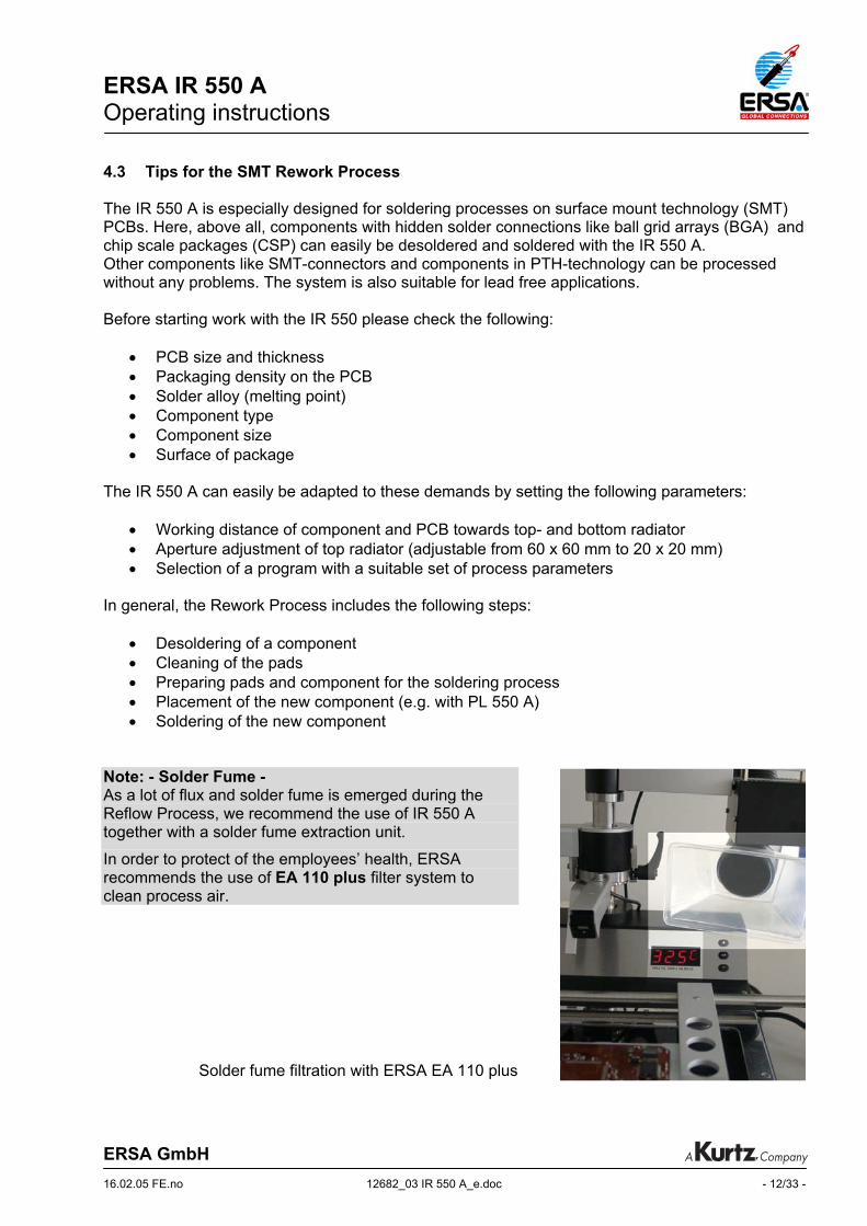
Note: - Solder Fume - As a lot of flux and solder fume is emerged during the Reflow Process, we recommend the use of IR 550 A together with a solder fume extraction unit.
In order to protect of the employees’ health, ERSA recommends the use of EA 110 plus filter system to clean process air.
Solder fume filtration with ERSA EA 110 plus
ERSA IR 550 A Operating instructions
ERSA GmbH 16.02.05 FE.no 12682_03 IR 550 A_e.doc - 13/33 -
5 Functional description For the Functional description of the DIGITAL 2000 A soldering station, please refer to chapter 5 of the DIGITAL 2000 A operating instructions (3BA00044). 5.1 Functional elements of IR 550 A
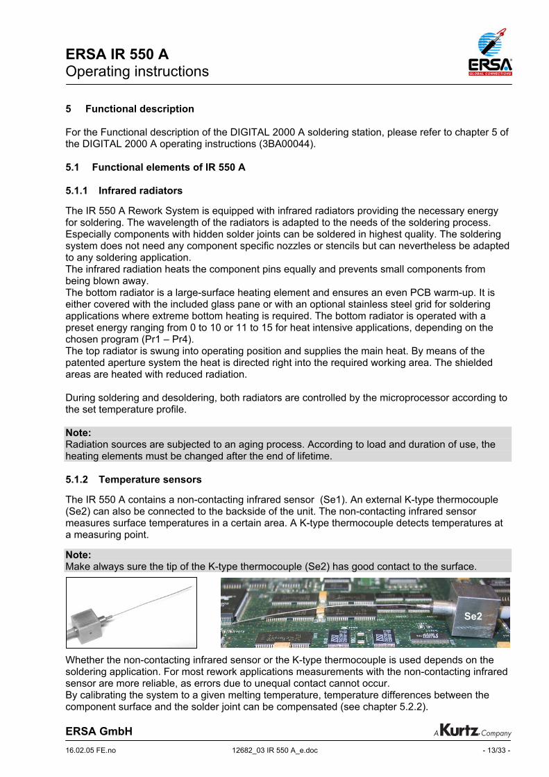
5.1.1 Infrared radiators The IR 550 A Rework System is equipped with infrared radiators providing the necessary energy for soldering. The wavelength of the radiators is adapted to the needs of the soldering process. Especially components with hidden solder joints can be soldered in highest quality. The soldering system does not need any component specific nozzles or stencils but can nevertheless be adapted to any soldering application. The infrared radiation heats the component pins equally and prevents small components from being blown away. The bottom radiator is a large-surface heating element and ensures an even PCB warm-up. It is either covered with the included glass pane or with an optional stainless steel grid for soldering applications where extreme bottom heating is required. The bottom radiator is operated with a preset energy ranging from 0 to 10 or 11 to 15 for heat intensive applications, depending on the chosen program (Pr1 – Pr4). The top radiator is swung into operating position and supplies the main heat. By means of the patented aperture system the heat is directed right into the required working area. The shielded areas are heated with reduced radiation. During soldering and desoldering, both radiators are controlled by the microprocessor according to the set temperature profile. Note: Radiation sources are subjected to an aging process. According to load and duration of use, the heating elements must be changed after the end of lifetime. 5.1.2 Temperature sensors The IR 550 A contains a non-contacting infrared sensor (Se1). An external K-type thermocouple (Se2) can also be connected to the backside of the unit. The non-contacting infrared sensor measures surface temperatures in a certain area. A K-type thermocouple detects temperatures at a measuring point. Note: Make always sure the tip of the K-type thermocouple (Se2) has good contact to the surface. Whether the non-contacting infrared sensor or the K-type thermocouple is used depends on the soldering application. For most rework applications measurements with the non-contacting infrared sensor are more reliable, as errors due to unequal contact cannot occur. By calibrating the system to a given melting temperature, temperature differences between the component surface and the solder joint can be compensated (see chapter 5.2.2).
Se2
ERSA IR 550 A Operating instructions
ERSA GmbH 16.02.05 FE.no 12682_03 IR 550 A_e.doc - 14/33 -
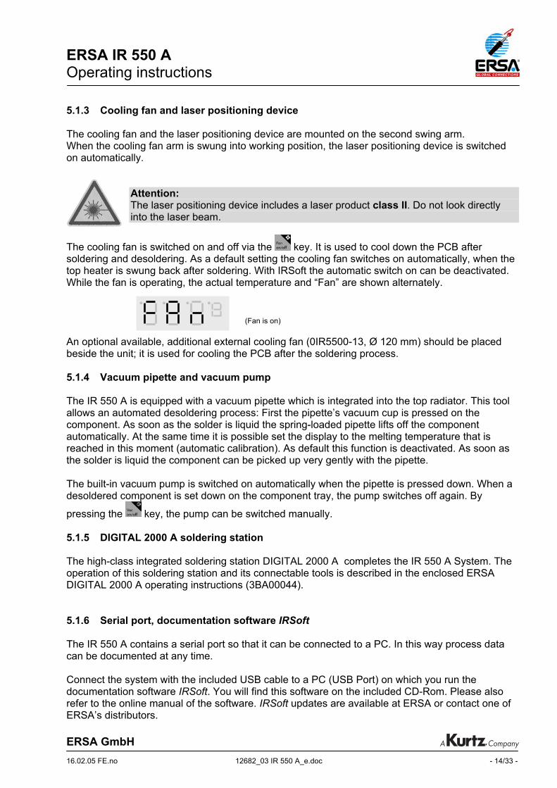
5.1.3 Cooling fan and laser positioning device The cooling fan and the laser positioning device are mounted on the second swing arm. When the cooling fan arm is swung into working position, the laser positioning device is switched on automatically.
Attention: The laser positioning device includes a laser product class II. Do not look directly into the laser beam.
The cooling fan is switched on and off via the key. It is used to cool down the PCB after soldering and desoldering. As a default setting the cooling fan switches on automatically, when the top heater is swung back after soldering. With IRSoft the automatic switch on can be deactivated. While the fan is operating, the actual temperature and “Fan” are shown alternately. An optional available, additional external cooling fan (0IR5500-13, Ø 120 mm) should be placed beside the unit; it is used for cooling the PCB after the soldering process. 5.1.4 Vacuum pipette and vacuum pump The IR 550 A is equipped with a vacuum pipette which is integrated into the top radiator. This tool allows an automated desoldering process: First the pipette’s vacuum cup is pressed on the component. As soon as the solder is liquid the spring-loaded pipette lifts off the component automatically. At the same time it is possible set the display to the melting temperature that is reached in this moment (automatic calibration). As default this function is deactivated. As soon as the solder is liquid the component can be picked up very gently with the pipette. The built-in vacuum pump is switched on automatically when the pipette is pressed down. When a desoldered component is set down on the component tray, the pump switches off again. By
pressing the key, the pump can be switched manually. 5.1.5 DIGITAL 2000 A soldering station The high-class integrated soldering station DIGITAL 2000 A completes the IR 550 A System. The operation of this soldering station and its connectable tools is described in the enclosed ERSA DIGITAL 2000 A operating instructions (3BA00044). 5.1.6 Serial port, documentation software IRSoft The IR 550 A contains a serial port so that it can be connected to a PC. In this way process data can be documented at any time. Connect the system with the included USB cable to a PC (USB Port) on which you run the documentation software IRSoft. You will find this software on the included CD-Rom. Please also refer to the online manual of the software. IRSoft updates are available at ERSA or contact one of ERSA’s distributors.
(Fan is on)

ERSA IR 550 A Operating instructions
ERSA GmbH 16.02.05 FE.no 12682_03 IR 550 A_e.doc - 15/33 -
5.2 Operation and program parameters The IR 550 A Rework System enables repair soldering based on parameters which are set and can be stored by the user. In total, four programs (Pr1 to Pr4) can be saved and modified at any time. (For more storage options use the documentation software IRSoft, see 5.1.6) The active program, all parameters and the actual temperature value are visualized over a four digit LED display. Display of IR 550 A:
Digits 1 to 3 display actual temperature values and the settings of all parameters. Digit 4 displays the units or symbols for each parameter. The LED dots are correlated to the parameters T1, T2, TL und T3. They light up during the setting of the correlated parameter and as soon as the measured value reaches one of these parameters during the process is running. The unit is operated via an external keypad with six function keys: Key Function
change program; increase parameter value 1)
choose program; change parameter, store values 2)
change program; decrease parameter value
Key Function Adjust display to melting
temperature 3)
Switching of vacuum pump
Switching of cooling fan
1) Special function: Keep pressing at switch-on shows firmware version 2) Special function: Keep pressing at switch-on load factory settings 3) Special function: Reset calibration factor when top radiator is in neutral position
digit 1 2 3 4
LED dots
ERSA IR 550 A Operating instructions
ERSA GmbH 16.02.05 WE.no 12682_03 IR 550 A_e.doc - 16/33 -
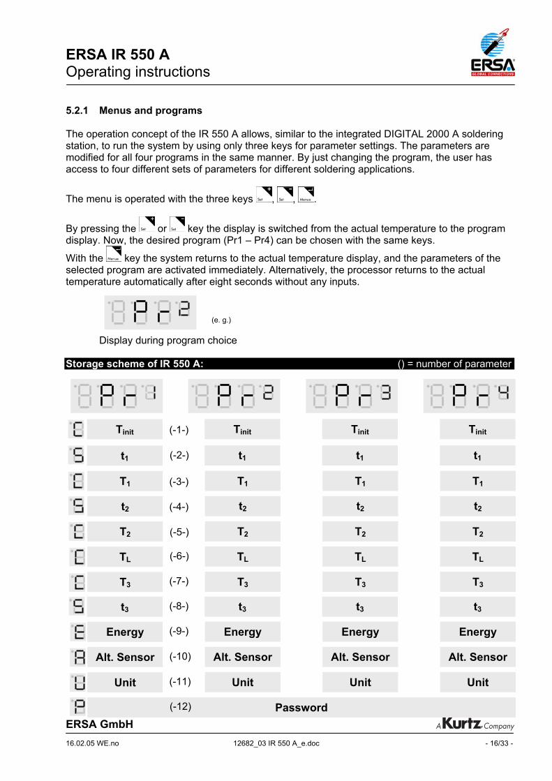
5.2.1 Menus and programs The operation concept of the IR 550 A allows, similar to the integrated DIGITAL 2000 A soldering station, to run the system by using only three keys for parameter settings. The parameters are modified for all four programs in the same manner. By just changing the program, the user has access to four different sets of parameters for different soldering applications.
The menu is operated with the three keys , , .
By pressing the or key the display is switched from the actual temperature to the program display. Now, the desired program (Pr1 – Pr4) can be chosen with the same keys.
With the key the system returns to the actual temperature display, and the parameters of the selected program are activated immediately. Alternatively, the processor returns to the actual temperature automatically after eight seconds without any inputs.
Display during program choice
Storage scheme of IR 550 A: () = number of parameter
(e. g.)
T1 T1 T1 T1
T2 T2 T2 T2
t2 t2 t2 t2
TL TL TL TL
T3 T3 T3 T3
Energy Energy Energy Energy
Unit Unit Unit Unit
Password
Alt. Sensor Alt. Sensor Alt. Sensor Alt. Sensor
t1 t1 t1 t1
Tinit Tinit Tinit Tinit
t3 t3 t3 t3
(-1-)
(-2-)
(-3-)
(-4-)
(-5-)
(-6-)
(-7-)
(-8-)
(-9-)
(-10)
(-11)
(-12)
ERSA IR 550 A Operating instructions
ERSA GmbH 16.02.05 WE.no 12682_03 IR 550 A_e.doc - 17/33 -
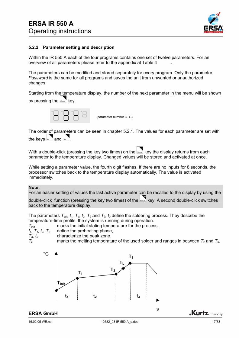
5.2.2 Parameter setting and description Within the IR 550 A each of the four programs contains one set of twelve parameters. For an overview of all parameters please refer to the appendix at Table 4 . The parameters can be modified and stored separately for every program. Only the parameter Password is the same for all programs and saves the unit from unwanted or unauthorized changes. Starting from the temperature display, the number of the next parameter in the menu will be shown
by pressing the key. The order of parameters can be seen in chapter 5.2.1. The values for each parameter are set with
the keys and .
With a double-click (pressing the key two times) on the key the display returns from each parameter to the temperature display. Changed values will be stored and activated at once. While setting a parameter value, the fourth digit flashes. If there are no inputs for 8 seconds, the processor switches back to the temperature display automatically. The value is activated immediately. Note: For an easier setting of values the last active parameter can be recalled to the display by using the
double-click function (pressing the key two times) of the key. A second double-click switches back to the temperature display. The parameters Tinit, t1, T1, t2, T2 and T3, t3 define the soldering process. They describe the temperature-time profile the system is running during operation. Tinit marks the initial stating temperature for the process, t1, T1, t2, T2 define the preheating phase, T3, t3 characterize the peak zone. TL marks the melting temperature of the used solder and ranges in between T2 and T3.
°C
s
(parameter number 3, T1)
T1
Tinit
T2
TL T3
t1 t2 t3

ERSA IR 550 A Operating instructions
ERSA GmbH 16.02.05 WE.no 12682_03 IR 550 A_e.doc - 18/33 -
Tinit initial temperature (-1-) The starting temperature Tinit is the first temperature value reached during the soldering process. Tinit is the reference starting temperature for repeatable processes. To reach Tinit the unit operates only the bottom heating element to preheat the board. At Tinit both heaters are working.
The value for Tinit is set with the keys and .
Display until Tinit is reached t1 preheating time 1 (-2-) During the period defined by t1 the preheating proceeds with a user defined ramp rate up to T1.
The value for t1 is set with the keys and .
Display during setting of t1 T1 preheating temperature 1 (-3-) The preheating temperature T1 is the first temperature value reached during the soldering process. The warm-up to T1 occurs the within the permitted heat up rates defined for electronic components.
The value for T1 is set with the keys and .
Display during setting of T1 t2 preheating time 2 (-4-) During the period defined by t2 the preheating proceeds with a slow ramp rate to T2 or T1 is kept nearly constant.
The value for t2 is set with the keys and .
Display during setting of t2
(e.g.)
(e. g.)
(e. g.)
(e.g. LED dots flashing, bottom heat only)

ERSA IR 550 A Operating instructions
ERSA GmbH 16.02.05 WE.no 12682_03 IR 550 A_e.doc - 19/33 -
T2 preheating temperature 2 (-5-) At the end of time the preheating temperature T2 is reached. Preheating of PCB and component is finished at this time. Fluxes have been activated.
The value for T2 is set with the keys and .
Display during setting of T2 TL liquidus temperature (-6-) The liquidus temperature TL defines the temperature when the used solder (-paste) begins to melt and gets liquid. The liquidus temperature is used to calibrate the actual temperature to the temperature at the solder joint and adjust the display to this value (calibration) . There are two possibilities to achieve this:
• Automatic adaptation during desoldering (default: off) The adaptation of the display to the stored value of TL is automatically activated during desoldering, when the spring loaded pipette lifts the component and thereby indicates that the solder has molten at this time.
• Manual adaptation (recommended)
By viewing the soldering process (i.e. by camera support) the user can press the key as soon as the solder becomes liquid and by this action set the actual display to the stored value of TL .
The value for TL is set with the keys and .
Display during setting of TL See Table 3 „Melting temperatures of solder alloys”. T3 peak temperature (-7-) When T2 is reached, the unit continues to heat up with the maximum permitted heat-up rate towards peak temperature T3. At peak temperature the soldering process ends (when t3 = 0s). Component and PCB can be cooled down using the built-in cooling fan.
The value for T3 is set with the keys and .
Display during setting of T3
(e g.)
(e. g.)
(e.g.)
ERSA IR 550 A Operating instructions
ERSA GmbH 16.02.05 WE.no 12682_03 IR 550 A_e.doc - 20/33 -
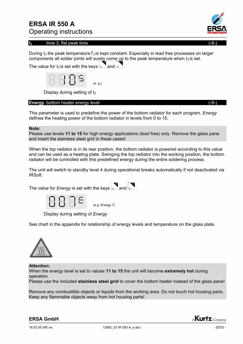
t3 time 3, flat peak time (-8-) During t3 the peak temperatureT3 is kept constant. Especially in lead free processes on larger components all solder joints will surely come up to the peak temperature when t3 is set.
The value for t3 is set with the keys and .
Display during setting of t3 Energy bottom heater energy level (-9-) This parameter is used to predefine the power of the bottom radiator for each program. Energy defines the heating power of the bottom radiator in levels from 0 to 15. Note: Please use levels 11 to 15 for high energy applications (lead free) only. Remove the glass pane and insert the stainless steel grid in these cases! When the top radiator is in its rear position, the bottom radiator is powered according to this value and can be used as a heating plate. Swinging the top radiator into the working position, the bottom radiator will be controlled with this predefined energy during the entire soldering process. The unit will switch to standby level 4 during operational breaks automatically if not deactivated via IRSoft.
The value for Energy is set with the keys and .
Display during setting of Energy See chart in the appendix for relationship of energy levels and temperature on the glass plate.
Attention: When the energy level is set to values 11 to 15 the unit will become extremely hot during operation. Please use the included stainless steel grid to cover the bottom heater instead of the glass pane! Remove any combustible objects or liquids from the working area. Do not touch hot housing parts. Keep any flammable objects away from hot housing parts!
(e.g. Energy 7)
(e. g.)

ERSA IR 550 A Operating instructions
ERSA GmbH 16.02.05 WE.no 12682_03 IR 550 A_e.doc - 21/33 -
Alternative Sensor (-10) In addition to the built-in non-contacting infrared sensor (Se1) the user can connect an external K-type thermocouple (Se2) for temperature measurement. The parameter Alternative Sensor is used to select the sensor. The signal of the selected sensor will be displayed and used for process control.
The value for Alternative Sensor is set with the keys and .
Display during setting of Alternative Sensor
Unit temperature unit (-11) The parameter Unit is used to change the temperature displayed in °C or °F within one program.
The value for Unit is set with the keys and .
Display during setting of Unit Password (-12) To save the unit from unwanted or unauthorized changes the parameter Password is used. When its value is set to 0 (Display 000) password protection is inactive. After setting a numeric
combination with and and storage by pressing the key, three lines (Display - - -) indicate the active password protection of the unit. All parameters can still be displayed, changes
are only possible by input of the correct numeric combination using and to set the value
and the key to confirm. The programs can be changed when the password protection is active.
Display during setting of Password The parameter Password stays the same for all programs and can be activated or inactivated within each program. The system requests the input of the right password (Display - - -) before any changes are possible. The password can also be activated and be deactivated the IRSoft software. For reset of the password please see chapter 5.2.5 Factory settings.
(e.g. „C“ for Celsius)
(e.g.)
(e.g. „Se1“ for non contacting sensor)
ERSA IR 550 A Operating instructions
ERSA GmbH 16.02.05 WE.no 12682_03 IR 550 A_e.doc - 22/33 -
5.2.3 Operating process „soldering“ The parameters of each program define the temperature profile for the soldering process which is carried out in the following steps:
READY
• The unit is ready for operation, the bottom radiator is preheated, the top radiator is in its rear position over the component tray.
• The PCB is clamped in the holder and positioned over the bottom radiator of the IR 550 A. The component to be soldered should be placed in the center of top and bottom radiator. This position can easily be checked using the laser positioning device.
• The parameters of the last chosen program are active.
• The display shows the actual temperature of the selected sensor.
START
• As soon as the top radiator is swivelled into working position the process starts. The radiators heat up the assembly group. As long as Tinit is not reached only the bottom heater is active. When Tinit is reached also the top heater starts to heat the component.
• During the component warm-up the LED-dots in the display indicate when T1, T2,T3 and TL are reached.
• If the melting of the solder is watched, the user can adjust the display to the preset liquid temperature TL by pressing the key.
• When TL is reached it is indicated by a pulsing acoustic signal*.
END • As soon as T3 is reached (and the time t3 is run out) the heating process is finished. The
acoustic signal changes to a constant beep*, the radiator’s heating power is reduced.
• When the top radiator is swung back to rear position the cooling fan is switched on automatically.
• By swinging the second arm to working position the assembly will be cooled down. Use the
key to manually switch on or off the cooling fan. * The acoustic signals can be changed the IRSoft:
- Buzzer on
- Buzzer off
- short buzzer signals (default)
ERSA IR 550 A Operating instructions
ERSA GmbH 16.02.05 WE.no 12682_03 IR 550 A_e.doc - 23/33 -
5.2.4 Operating process „desoldering“
READY • The unit is ready for operation, the bottom radiator is preheated, the top radiator is in its
rear position over the component tray. • The PCB is clamped in the holder and has to be positioned over the bottom radiator of the
IR 550 A. The component to be soldered should be placed in the center of top and bottom radiator. This position can easily be checked using the laser-positioning device.
• The parameters of the last chosen program are active. • The display shows the actual temperature of the selected sensor.
START • As soon as the top radiator is swivelled into working position, the process starts. The
radiators heat up the assembly. As long as Tinit is not reached only the bottom heater is active. When Tinit is reached also the top heater starts to heat the component.
• As soon as the vacuum pipette is pressed down, the vacuum pump switches on. The radiators heat up component and PCB to peak temperature T3 with the maximum possible
heating rate. The operator can interrupt the process by pressing the key and start again.
END • When the solder melts the component is automatically lifted off by the spring-loaded
vacuum pipette or taken away manually with the pipette or a pair of tweezers. In the first case, the display can also be adjusted automatically to TL. The process ends, indicated by an acoustic signal (see page 21), and the radiators’ heating power is reduced.
• When the top radiator is swung back to rear position, the desoldered component on the vacuum pipette can be set onto the component tray by pressing the pipette down again. The vacuum pump is switched off at the same time. The cooling fan is switched on automatically.
• By swinging the second arm to working position the assembly will be cooled down. Use the
key to manually switch on or off the cooling fan.
5.2.5 Factory settings
Password Program Auto Fan Auto Cal Buzzer Standby 0 (inactive) 1 on off short signals on
To recall the factory settings you have to switch off the IR 550 A unit at first. Then switch on the unit again and press the key and keep it. All user defined parameters deleted, the factory settings are loaded.
To display the actual firmware version of the unit, press the button immediately after switching on the unit. (Display 0180 is version 1.80) The firmware version is also indicated in the IRSoft status window.
Table 1 Factory setting in the appendix shows the preset parameters of all four programs. As electronic assemblies are very different, ERSA recommends to adapting the parameters for every single customer application.

ERSA IR 550 A Operating instructions
ERSA GmbH 16.02.05 WE.no 12682_03 IR 550 A_e.doc - 24/33 -
6 Error diagnosis and repair The unit contains an automatic information management. It detects critical errors as well as information for the operator. Depending on the message the unit might be inoperable.
Info display Error display
If an info or error occurs please refer to Table 2 Info and Error description. To confirm an error press the key.
If the error continues to occur, you have to go on with the error analysis. Please contact your supplier or ERSA directly.
Attention: Repairs should only be carried out by qualified staff. The unit contains alive parts. Inexperienced work is extremely dangerous! Further errors: Unit does not operate, display stays dark.
• Is the main cable plugged in correctly? connect the unit to the power supply.
• Are the main switches of the basic unit and the DIGITAL 2000 A soldering station switched on?
Switch on the units.
• Is a fuse blown? Exchange defective fuse. Note that there might be a serious error within the unit causing
defective fuses.
(e.g. Info 6) (e.g. Error 7)
ERSA IR 550 A Operating instructions
ERSA GmbH 16.02.05 WE.no 12682_03 IR 550 A_e.doc - 25/33 -
Bottom radiator stays cold.
• Is the cooling fan running? the bottom radiator remains switched off if the cooling fan runs (Display FAn). Switch off
the cooling fan.
• Is the parameter of Energy in the active program set to 0? Set the value of Energy > 0.
Component cannot be removed with of the vacuum pipette.
• Is the vacuum pump running and do you have a vacuum at the silicone cup? Switch on the pump.
• Is the silicone cup damaged (Leakage)? Exchange silicone cup.
• Is the filter at the backside of the unit clogged? Exchange the filter.
Laser-positioning device or cooling fan do not operate.
• Is the supply cable from the backside of the unit to the arm plugged in or damaged? Plug in the cable or exchange damaged cable.
• Is the rotor of the cooling fan blocked? Loosen the blockage.
• Is the laser-positioning device aligned properly? Align laser-positioning device.
Unit does not react on external keypad.
• Is the keypad properly connected to the unit? Connect the keypad.
• Is the keypad cable damaged? Exchange keypad with cable.
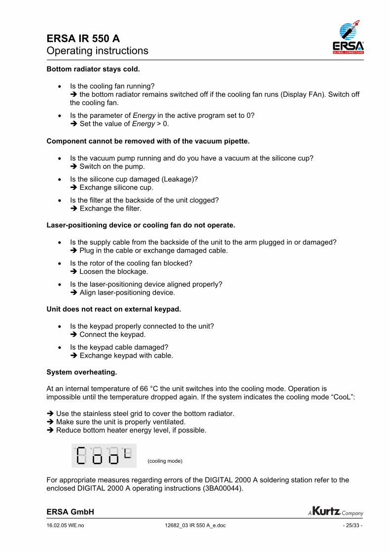
System overheating. At an internal temperature of 66 °C the unit switches into the cooling mode. Operation is impossible until the temperature dropped again. If the system indicates the cooling mode “CooL”:
Use the stainless steel grid to cover the bottom radiator. Make sure the unit is properly ventilated. Reduce bottom heater energy level, if possible.
For appropriate measures regarding errors of the DIGITAL 2000 A soldering station refer to the enclosed DIGITAL 2000 A operating instructions (3BA00044).
(cooling mode)

ERSA IR 550 A Operating instructions
ERSA GmbH 16.02.05 WE.no 12682_03 IR 550 A_e.doc - 26/33 -
7 Maintenance Note: Only use genuine ERSA consumables and spare parts in order to ensure reliable function and to maintain the unit’s warranty.
Attention: Housing parts of the unit can still be hot after switching off the unit. Clean the unit only when it is switched off and has cooled down to room temperature. Please do not use any dangerous or flammable solvents for cleaning. Cleaning of the unit: Use a dry or moist towel to clean the unit. The component tray and the glass pate covering the bottom radiator can be cleaned with a hard and dull device and a towel from solder- and flux splashes. The glass plate can also be removed for cleaning. See chap. 8 “spare parts and options” Exchange of a silicone cup: To exchange a used silicone cup, switch off the unit and wait until vacuum pipette and top radiator have cooled. Remove the silicone cup downwards from the pipette and repace it by a new one. Suction cups with Ø 2 mm and Ø 3.5 mm are mounted directly – without adapter – on the vaccum pipe! Adjustment of the laser positioning device: The laser positioning device can be readjusted at two points:
1. Adjustment screws at the cooling fan housing: Here the angle of the laser positioning device can be re-adjusted in Y-direction.
2. Adjusting ring at the arm of cooling fan and laser positioning device: Re-adjustment of the laser dot in X-direction.
When the laser dot is adjusted properly it marks exactly the spot where the pipette contacts the board when pressed down.

ERSA IR 550 A Operating instructions
ERSA GmbH 16.02.05 WE.no 12682_03 IR 550 A_e.doc - 27/33 -
8 Spare parts and options Name Order number
IR 550 A microprocessor controlled rework system 0IR550A Silicone suction cup ∅ 8 mm 0IR4520-01 Silicone suction cup ∅ 5 mm 0IR4520-02 Silicone suction cup ∅ 2 mm 0IR4520-03 Viton suction cup ∅ 8 mm 0IR4520-04 Viton suction cup ∅ 5 mm 0IR4520-05 Viton suction cup ∅ 3.5 mm 0IR4520-06 External keypad 0IR5500-04 USB cable 3ET00241 Controller board 0IR5500-06 Top radiator heating element 230 V (with TC) 0IR5500-31 Top radiator heating element 115 V (with TC) 0IR5500-32 Filter unit complete (for vacuum) 0IR4500-23 X-Y PCB table (option) 0IR5500-01 PCB Holder (option) 0PH100 K-Type Thermocouple with support cube 0IR6500-01 K-Type Thermocouple wire IR (option) 0IR4510-02 K-Type Thermocouple wire DIG (option) 0DIG207 Stainless steel grid 0IR5500-03 External cooling fan for boards ∅ 120 mm (option) 0IR5500-13 Reflective tape (25 mm x 1 m) 0IR4500-40 Capton tape (25 mm x 10 m) 0IR4500-07 Flux-Pen with flux IF 8001 4FMJF8001-PEN No-Clean flux cream 0FMKANC32-005 You will find further spare parts in a separate spare part list. For spare parts and order numbers of the DIGITAL 2000 A soldering station, please refer to the ERSA DIGITAL 2000 A operating instructions (3BA00044). Viton ® is a registered trademark of DuPont Dow Elastomers
ERSA IR 550 A Operating instructions
ERSA GmbH 16.02.05 WE.no 12682_03 IR 550 A_e.doc - 28/33 -
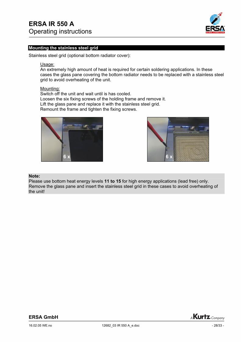
Mounting the stainless steel grid
Stainless steel grid (optional bottom radiator cover):
Usage: An extremely high amount of heat is required for certain soldering applications. In these cases the glass pane covering the bottom radiator needs to be replaced with a stainless steel grid to avoid overheating of the unit. Mounting: Switch off the unit and wait until is has cooled. Loosen the six fixing screws of the holding frame and remove it. Lift the glass pane and replace it with the stainless steel grid. Remount the frame and tighten the fixing screws.
Note: Please use bottom heat energy levels 11 to 15 for high energy applications (lead free) only. Remove the glass pane and insert the stainless steel grid in these cases to avoid overheating of the unit!
6 x 6 x
ERSA IR 550 A Operating instructions
ERSA GmbH 16.02.05 WE.no 12682_03 IR 550 A_e.doc - 29/33 -
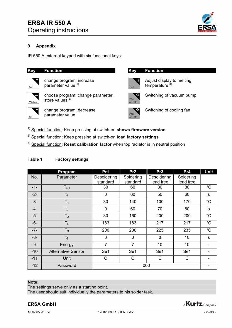
9 Appendix IR 550 A external keypad with six functional keys: Key Function
change program; increase parameter value 1)
choose program; change parameter, store values 2)
change program; decrease parameter value
Key Function Adjust display to melting
temperature 3)
Switching of vacuum pump
Switching of cooling fan
1) Special function: Keep pressing at switch-on shows firmware version 2) Special function: Keep pressing at switch-on load factory settings 3) Special function: Reset calibration factor when top radiator is in neutral position
Table 1 Factory settings
Program Pr1 Pr2 Pr3 Pr4 Unit No. Parameter Desoldering
standard Soldering standard
Desoldering lead free
Soldering lead free
-1- Tinit 30 60 30 80 °C
-2- t1 0 60 50 60 s
-3- T1 30 140 100 170 °C
-4- t2 0 60 70 60 s -5- T2 30 160 200 200 °C
-6- TL 183 183 217 217 °C
-7- T3 200 200 225 235 °C
-8- t3 0 0 0 10 s
-9- Energy 7 7 10 10 - -10 Alternative Sensor Se1 Se1 Se1 Se1 - -11 Unit C C C C -
-12 Password 000 - Note: The settings serve only as a starting point. The user should suit individually the parameters to his solder task.

ERSA IR 550 A Operating instructions
ERSA GmbH 16.02.05 FE.no 12682_03 IR 550 A_e.doc - 30/33 -
Temperatures of the glass plate covering the bottom radiator over bottom radiator energy. During standby the heater is set to energy level 4.
0
50
100
150
200
250
300
0 1 2 3 4 5 6 7 8 9 10
Energy
Tem
p. [°
C]
Note: Please use levels 11 to 15 for high energy applications (lead free) only. Remove the glass pane and insert the stainless steel grid in these cases! Table 2 Info and Error description Inf / Err description possible reasons steps
Inf 0 Unit too hot Unit was operated at high temperatures for long time
Make sure the unit is properly ventilated. Reduce energy level, if possible. Use grid!
Err 3 Error thermocouple top heater
TC connection in top heater is open
Exchange top heater with thermocouple
Inf 6 Sensor reading incorrect Se1 or Se2 do not read any temperature increase though the heating is on
Ensure Se1 or Se2 are working and are set to the object to measure.
Err 7 Error external thermocouple
cracked thermo wire or no thermocouple connected
Connect a working thermocouple
Err 9 parameter in EEPROM damaged
Error in program memory Keep the key pressed
when switching the unit so that the factory settings will be loaded. If error returns frequently: exchange the control board.
standby

ERSA IR 550 A Operating instructions
ERSA GmbH 16.02.05 FE.no 12682_03 IR 550 A_e.doc - 31/33 -
Table 3 Melting temperatures of solder alloys alloy TL note 58 Sn / 42 In ~145 °C Lead-free * 62,5 Sn / 36,1 Pb / 1,4 Ag 179 °C 63Sn / 37 Pb 183 °C standard 60 Sn / 40 Pb 188 °C 62 Sn / 36 Pb / 2 Ag 189 °C 94,25 Sn / 2 Ag / 0,75 Cu / 3 Bi ~ 211 °C Lead-free,* Reflow 97,5 Sn / 2,5 Ag ~ 215 °C Lead-free * 50 Sn / 50 Pb 216 °C 95,5 Sn / 3,8 Ag / 0,7 Cu 217 °C Lead-free 96,5 Sn / 3,5 Ag 221 °C Lead-free, Reflow 40 Sn / 60 Pb 238 °C 95,5Sn / 4 Cu / 0,5 Ag ~ 260 °C Lead-free *
* for some solder alloys an exact melting temperature cannot be given as the solder is getting liquid within a temperature range.
Table 4 Parameter overview
No parameter description display in 4. digit range* -1- Tinit initial temperature C/F 30 – 150 °C
-2- t1 preheating time 1 S 0 – 300 s -3- T1 preheating temperature 1 C/F, dot T1 30 – 260 °C
-4- t2 preheating time 2 S 0 – 300 s
-5- T2 preheating temperature 2 C/F, dot T2 30 – 260 °C -6- TL liquidus temperature C/F, dot TL 100 – 300 °C
-7- T3 peak temperature C/F, dot T3 100 – 300 °C
-8- t3 time 3, flat peak time S 0 – 60 s -9- Energy bottom heater energy level E 0 – 15
-10 Alternative Sensor sensor selection A Se1 or Se2
-11 Unit temperature unit U C or F
-12 Password password P 000 - 999
* The range from the aforementioned values can differ by using different firmware versions. (Version 1.80)

ERSA IR 550 A Operating instructions
ERSA GmbH 16.02.05 FE.no 12682_03 IR 550 A_e.doc - 32/33 -
10 Index alloy ............................................................ 31
Alternative Sensor ...................................... 21
aperture system.......................................... 10
BGA............................................................ 12
bottom radiator ........................... 2, 13, 25, 30
calibration ................................................... 19
component tray......................................... 2, 9
cooling fan........................................ 2, 14, 25
cooling mode.............................................. 25
CSP............................................................ 12
defects........................................................ 24
desoldering................................................. 23
DIGITAL 2000 A ......................................... 14
display .................................................... 2, 15
double-click ................................................ 17
Energy ........................................................ 20
error diagnosis............................................ 24
external keypad ................................ 2, 15, 25
factory settings ........................................... 23
filter............................................................. 25
heating plate............................................... 20
infrared sensor ....................................... 2, 13
K-type thermocouple .................................. 13
laser positioning device .............. 2, 14, 25, 26
overheating................................................. 25
parameters.................................................. 17
Password .................................................... 21
reset............................................................ 21
rework steps ............................................... 12
save energy ................................................ 11
serial port .................................................... 14
silicone cup................................................. 26
solder alloys................................................ 31
soldering ..................................................... 22
stainless steel grid ...................................... 28
storage scheme .......................................... 16
temperature profile...................................... 17
temperature T1............................................ 18
temperature T2............................................ 19
temperature T3............................................ 19
temperature Tinit .......................................... 18
temperature TL............................................ 19
thermocouple .............................................. 13
time t1.......................................................... 18
time t2.......................................................... 18
time t3.......................................................... 20
top radiator.............................................. 2, 13
Unit ............................................................. 21
vacuum pipette ................................. 2, 14, 25
vacuum pump ............................................. 14
ERSA IR 550 A Operating instructions
ERSA GmbH 16.02.05 FE.no 12682_03 IR 550 A_e.doc - 33/33 -
11 Warranty ERSA has produced these Operating Instructions with the utmost care. Nevertheless, we cannot provide any guarantee regarding the content, completeness or quality of the information in these Instructions. The content is regularly updated and adapted to current conditions. We have gathered all data published in these Operating Instructions, as well as data on products and procedures, to the best of our knowledge, by means of state-of-the-art technical aids. These data are provided without obligation, and do not relieve the user of the responsibility for inspecting the equipment before its use. We assume no responsibility for violations of the protective rights of third parties, or for applications and procedures without our prior express and written confirmation. Technical information is subject to change without notice in the interest of improving the product. Within the bounds of legal possibility, liability for direct damage, consequential damage and third-party damage resulting from the acquisition of this product are precluded. All rights reserved. This manual may not be reproduced, transmitted or translated into another language, even in excerpt form, without the written approval of ERSA GmbH.
www.ersa.com