12ft octagon bayside gazebo assembly manual … · 12ft octagon bayside gazebo assembly manual...
TRANSCRIPT
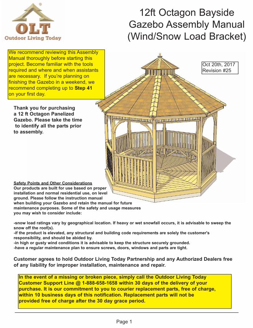
12ft Octagon BaysideGazebo Assembly Manual(Wind/Snow Load Bracket)
Page 1
Thank you for purchasing a 12 ft Octagon Panelized Gazebo. Please take the timeto identify all the parts prior
to assembly.
Safety Points and Other ConsiderationsOur products are built for use based on proper installation and normal residential use, on level ground. Please follow the instruction manual when building your Gazebo and retain the manual for future maintenance purposes. Some of the safety and usage measures you may wish to consider include:
-snow load ratings vary by geographical location. If heavy or wet snowfall occurs, it is advisable to sweep thesnow off the roof(s). -if the product is elevated, any structural and building code requirements are solely the customer's responsibility, and should be abided by. -in high or gusty wind conditions it is advisable to keep the structure securely grounded. -have a regular maintenance plan to ensure screws, doors, windows and parts are tight.
Customer agrees to hold Outdoor Living Today Partnership and any Authorized Dealers freeof any liability for improper installation, maintenance and repair.
Oct 20th, 2017Revision #25
In the event of a missing or broken piece, simply call the Outdoor Living TodayCustomer Support Line @ 1-888-658-1658 within 30 days of the delivery of your purchase. It is our commitment to you to courier replacement parts, free of charge, within 10 business days of this notification. Replacement parts will not be provided free of charge after the 30 day grace period.
We recommend reviewing this AssemblyManual thoroughly before starting this project. Become familiar with the toolsrequired and where and when assistantsare necessary. If you’re planning on finishing the Gazebo in a weekend, werecommend completing up to Step 41on your first day.
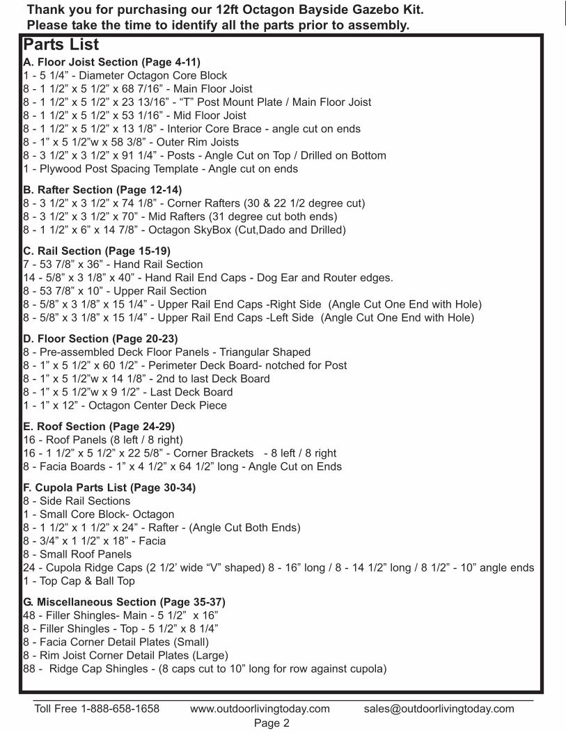
Thank you for purchasing our 12ft Octagon Bayside Gazebo Kit.Please take the time to identify all the parts prior to assembly.
Toll Free 1-888-658-1658 www.outdoorlivingtoday.com [email protected] 2
Parts ListA. Floor Joist Section (Page 4-11)1 - 5 1/4” - Diameter Octagon Core Block 8 - 1 1/2” x 5 1/2” x 68 7/16” - Main Floor Joist8 - 1 1/2” x 5 1/2” x 23 13/16” - “T” Post Mount Plate / Main Floor Joist8 - 1 1/2” x 5 1/2” x 53 1/16” - Mid Floor Joist8 - 1 1/2” x 5 1/2” x 13 1/8” - Interior Core Brace - angle cut on ends8 - 1” x 5 1/2”w x 58 3/8” - Outer Rim Joists8 - 3 1/2” x 3 1/2” x 91 1/4” - Posts - Angle Cut on Top / Drilled on Bottom1 - Plywood Post Spacing Template - Angle cut on ends
B. Rafter Section (Page 12-14)8 - 3 1/2” x 3 1/2” x 74 1/8” - Corner Rafters (30 & 22 1/2 degree cut)8 - 3 1/2” x 3 1/2” x 70” - Mid Rafters (31 degree cut both ends)8 - 1 1/2” x 6” x 14 7/8” - Octagon SkyBox (Cut,Dado and Drilled)
C. Rail Section (Page 15-19)7 - 53 7/8” x 36” - Hand Rail Section14 - 5/8” x 3 1/8” x 40” - Hand Rail End Caps - Dog Ear and Router edges.8 - 53 7/8” x 10” - Upper Rail Section8 - 5/8” x 3 1/8” x 15 1/4” - Upper Rail End Caps -Right Side (Angle Cut One End with Hole)8 - 5/8” x 3 1/8” x 15 1/4” - Upper Rail End Caps -Left Side (Angle Cut One End with Hole)
D. Floor Section (Page 20-23)8 - Pre-assembled Deck Floor Panels - Triangular Shaped8 - 1” x 5 1/2” x 60 1/2” - Perimeter Deck Board- notched for Post8 - 1” x 5 1/2”w x 14 1/8” - 2nd to last Deck Board8 - 1” x 5 1/2”w x 9 1/2” - Last Deck Board1 - 1” x 12” - Octagon Center Deck Piece
E. Roof Section (Page 24-29)16 - Roof Panels (8 left / 8 right)16 - 1 1/2” x 5 1/2” x 22 5/8” - Corner Brackets - 8 left / 8 right8 - Facia Boards - 1” x 4 1/2” x 64 1/2” long - Angle Cut on Ends
F. Cupola Parts List (Page 30-34)8 - Side Rail Sections1 - Small Core Block- Octagon8 - 1 1/2” x 1 1/2” x 24” - Rafter - (Angle Cut Both Ends)8 - 3/4” x 1 1/2” x 18” - Facia8 - Small Roof Panels24 - Cupola Ridge Caps (2 1/2’ wide “V” shaped) 8 - 16” long / 8 - 14 1/2” long / 8 1/2” - 10” angle ends1 - Top Cap & Ball Top
G. Miscellaneous Section (Page 35-37)48 - Filler Shingles- Main - 5 1/2” x 16”8 - Filler Shingles - Top - 5 1/2” x 8 1/4”8 - Facia Corner Detail Plates (Small)8 - Rim Joist Corner Detail Plates (Large)88 - Ridge Cap Shingles - (8 caps cut to 10” long for row against cupola)
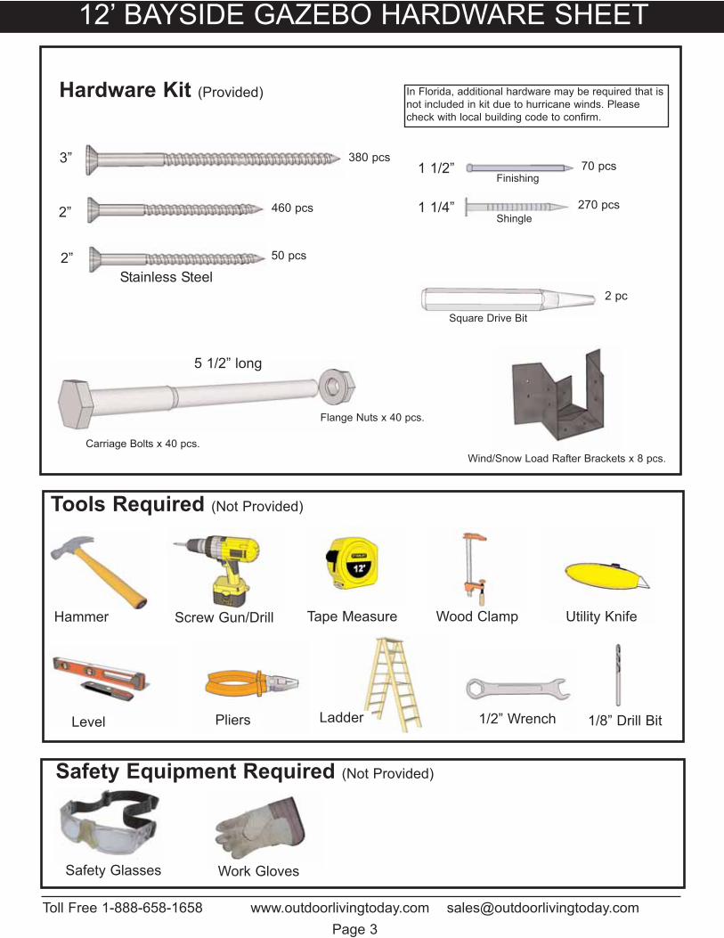
12’ BAYSIDE GAZEBO HARDWARE SHEET
Safety Glasses Work Gloves
Safety Equipment Required (Not Provided)
Ladder
Screw Gun/Drill Tape MeasureHammer Wood Clamp
Level Pliers
Tools Required (Not Provided)
1/8” Drill Bit
Toll Free 1-888-658-1658 www.outdoorlivingtoday.com [email protected] 3
Utility Knife
1/2” Wrench
2”
1 1/2”
1 1/4”
Finishing
Shingle
Hardware Kit (Provided)
3”
Carriage Bolts x 40 pcs.
Square Drive Bit
Flange Nuts x 40 pcs.
In Florida, additional hardware may be required that isnot included in kit due to hurricane winds. Pleasecheck with local building code to confirm.
2”Stainless Steel
5 1/2” long
380 pcs
460 pcs
50 pcs
70 pcs
270 pcs
2 pc
Wind/Snow Load Rafter Brackets x 8 pcs.
Toll Free 1-888-658-1658 www.outdoorlivingtoday.com [email protected] 4
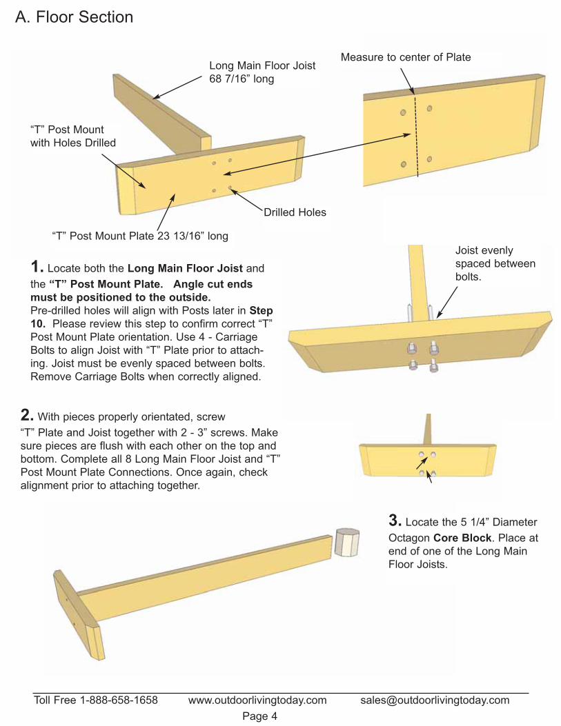
A. Floor Section
1. Locate both the Long Main Floor Joist andthe “T” Post Mount Plate. Angle cut endsmust be positioned to the outside.Pre-drilled holes will align with Posts later in Step10. Please review this step to confirm correct “T”Post Mount Plate orientation. Use 4 - CarriageBolts to align Joist with “T” Plate prior to attach-ing. Joist must be evenly spaced between bolts.Remove Carriage Bolts when correctly aligned.
2. With pieces properly orientated, screw“T” Plate and Joist together with 2 - 3” screws. Makesure pieces are flush with each other on the top andbottom. Complete all 8 Long Main Floor Joist and “T”Post Mount Plate Connections. Once again, checkalignment prior to attaching together.
Long Main Floor Joist 68 7/16” long
“T” Post Mountwith Holes Drilled
Drilled Holes
Measure to center of Plate
Joist evenlyspaced betweenbolts.
3. Locate the 5 1/4” DiameterOctagon Core Block. Place atend of one of the Long MainFloor Joists.
“T” Post Mount Plate 23 13/16” long
Toll Free 1-888-658-1658 www.outdoorlivingtoday.com [email protected] 5
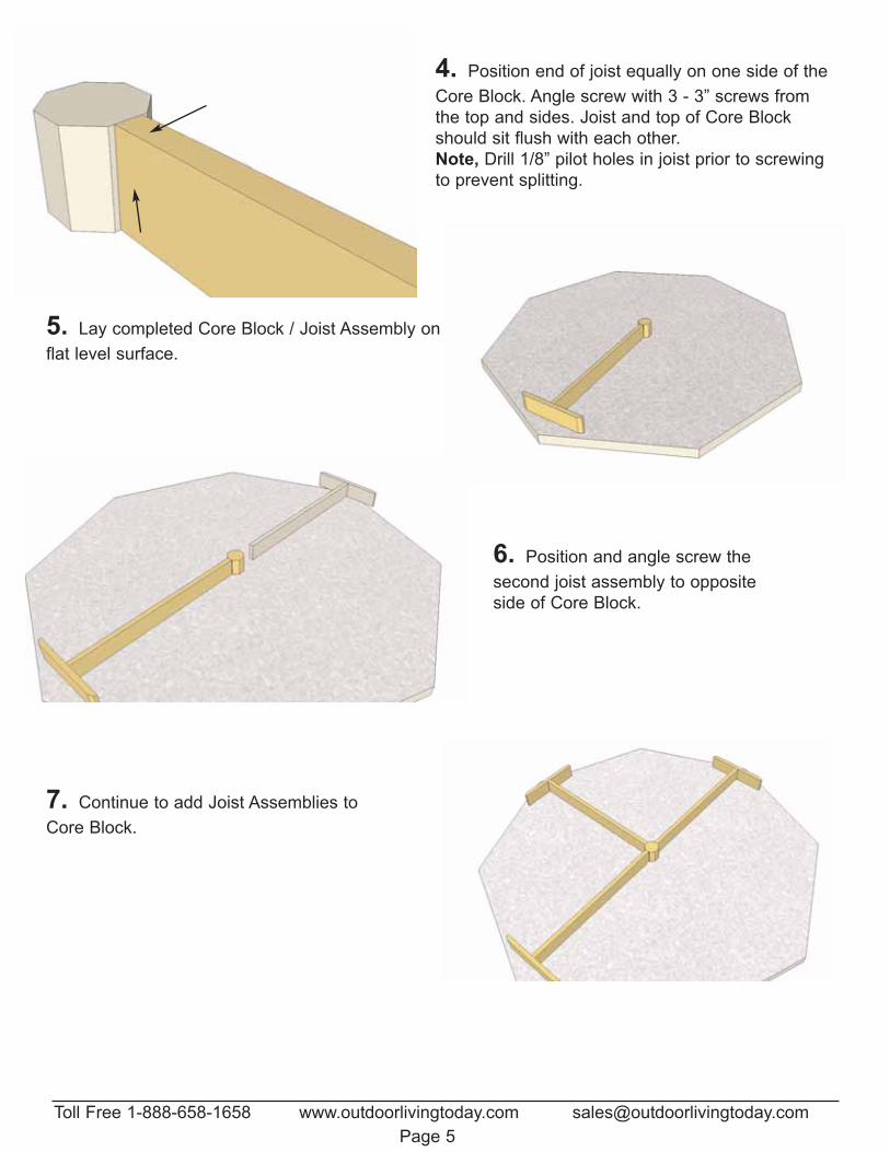
4. Position end of joist equally on one side of theCore Block. Angle screw with 3 - 3” screws fromthe top and sides. Joist and top of Core Blockshould sit flush with each other.Note, Drill 1/8” pilot holes in joist prior to screwingto prevent splitting.
5. Lay completed Core Block / Joist Assembly onflat level surface.
6. Position and angle screw the second joist assembly to oppositeside of Core Block.
7. Continue to add Joist Assemblies toCore Block.
Toll Free 1-888-658-1658 www.outdoorlivingtoday.com [email protected] 6
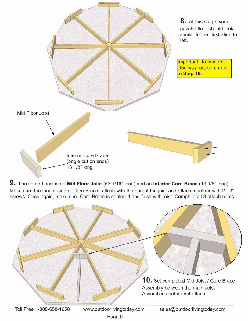
8. At this stage, yourgazebo floor should looksimilar to the illustration toleft.
9. Locate and position a Mid Floor Joist (53 1/16” long) and an Interior Core Brace (13 1/8” long).Make sure the longer side of Core Brace is flush with the end of the joist and attach together with 2 - 3”screws. Once again, make sure Core Brace is centered and flush with joist. Complete all 8 attachments.
Interior Core Brace(angle cut on ends)13 1/8” long
Mid Floor Joist
10. Set completed Mid Joist / Core BraceAssembly between the main JoistAssemblies but do not attach.
Important: To confirmDoorway location, referto Step 16.
Toll Free 1-888-658-1658 www.outdoorlivingtoday.com [email protected] 7
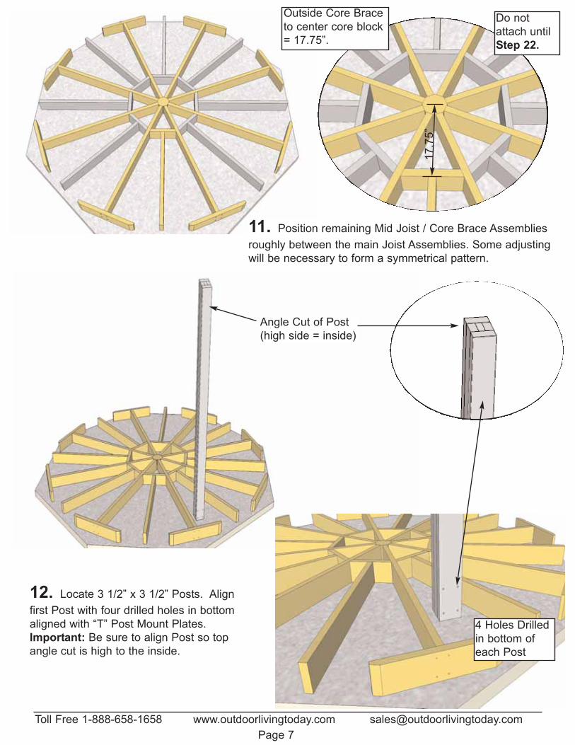
12. Locate 3 1/2” x 3 1/2” Posts. Alignfirst Post with four drilled holes in bottomaligned with “T” Post Mount Plates. Important: Be sure to align Post so topangle cut is high to the inside.
Angle Cut of Post(high side = inside)
11. Position remaining Mid Joist / Core Brace Assembliesroughly between the main Joist Assemblies. Some adjustingwill be necessary to form a symmetrical pattern.
4 Holes Drilledin bottom ofeach Post
Do notattach untilStep 22.
17.7
5”
Outside Core Brace to center core block = 17.75”.
Toll Free 1-888-658-1658 www.outdoorlivingtoday.com [email protected] 8
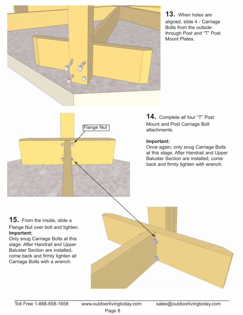
13. When holes arealigned, slide 4 - CarriageBolts from the outsidethrough Post and “T” PostMount Plates.
15. From the inside, slide aFlange Nut over bolt and tighten.Important: Only snug Carriage Bolts at thisstage. After Handrail and UpperBaluster Section are installed,come back and firmly tighten allCarriage Bolts with a wrench.
14. Complete all four “T” PostMount and Post Carriage Bolt attachments.
Important:Once again, only snug Carriage Boltsat this stage. After Handrail and UpperBaluster Section are installed, comeback and firmly tighten with wrench.
Flange Nut
Toll Free 1-888-658-1658 www.outdoorlivingtoday.com [email protected] 9
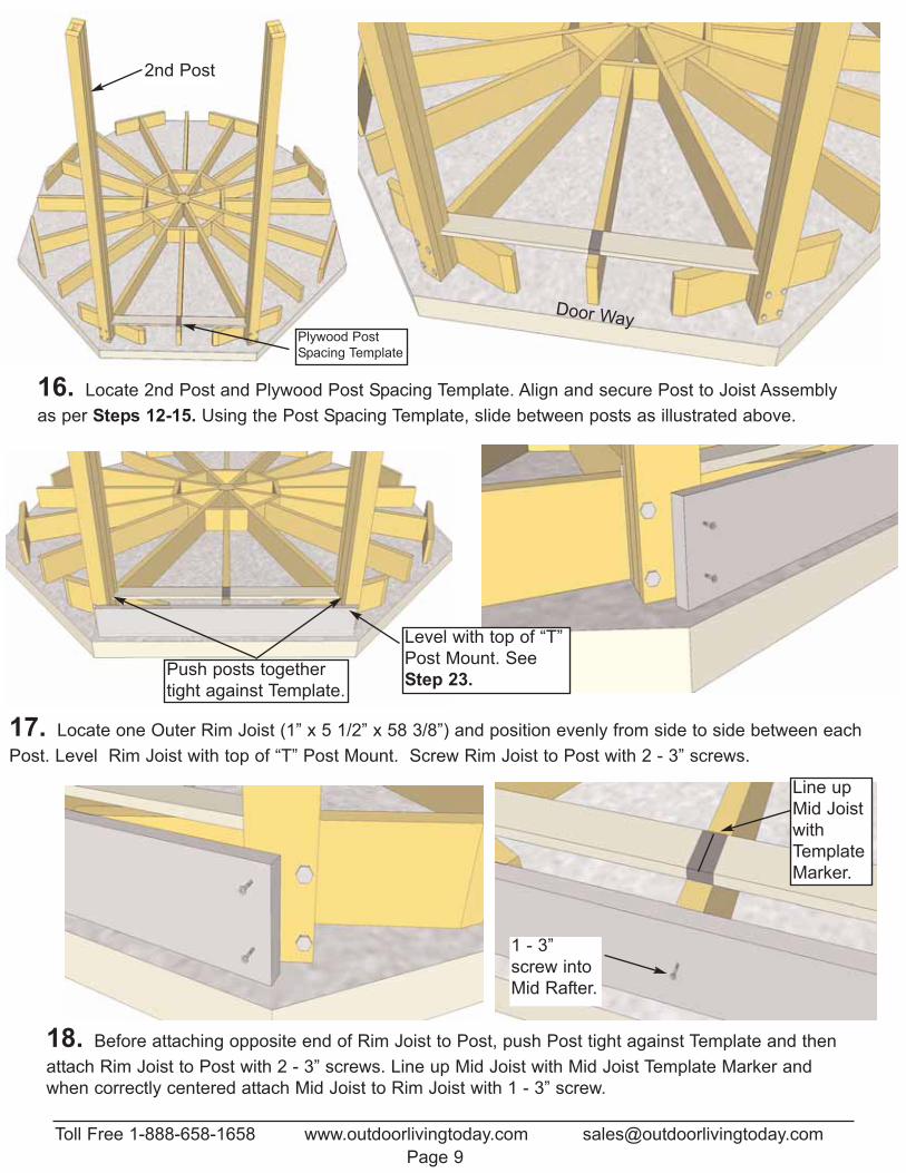
16. Locate 2nd Post and Plywood Post Spacing Template. Align and secure Post to Joist Assemblyas per Steps 12-15. Using the Post Spacing Template, slide between posts as illustrated above.
17. Locate one Outer Rim Joist (1” x 5 1/2” x 58 3/8”) and position evenly from side to side between eachPost. Level Rim Joist with top of “T” Post Mount. Screw Rim Joist to Post with 2 - 3” screws.
2nd Post
Plywood PostSpacing Template
Push posts togethertight against Template.
18. Before attaching opposite end of Rim Joist to Post, push Post tight against Template and thenattach Rim Joist to Post with 2 - 3” screws. Line up Mid Joist with Mid Joist Template Marker andwhen correctly centered attach Mid Joist to Rim Joist with 1 - 3” screw.
Line upMid JoistwithTemplateMarker.
1 - 3”screw intoMid Rafter.
Level with top of “T”Post Mount. SeeStep 23.
Door Way
Toll Free 1-888-658-1658 www.outdoorlivingtoday.com [email protected] 10
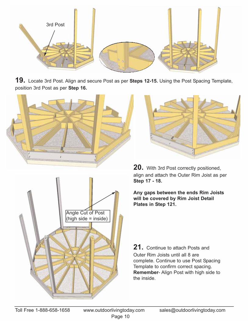
21. Continue to attach Posts andOuter Rim Joists until all 8 are complete. Continue to use Post SpacingTemplate to confirm correct spacing.Remember- Align Post with high side tothe inside.
19. Locate 3rd Post. Align and secure Post as per Steps 12-15. Using the Post Spacing Template,position 3rd Post as per Step 16.
3rd Post
20. With 3rd Post correctly positioned,align and attach the Outer Rim Joist as perStep 17 - 18.
Any gaps between the ends Rim Joistswill be covered by Rim Joist DetailPlates in Step 121.
Angle Cut of Post(high side = inside)
Toll Free 1-888-658-1658 www.outdoorlivingtoday.com [email protected] 11
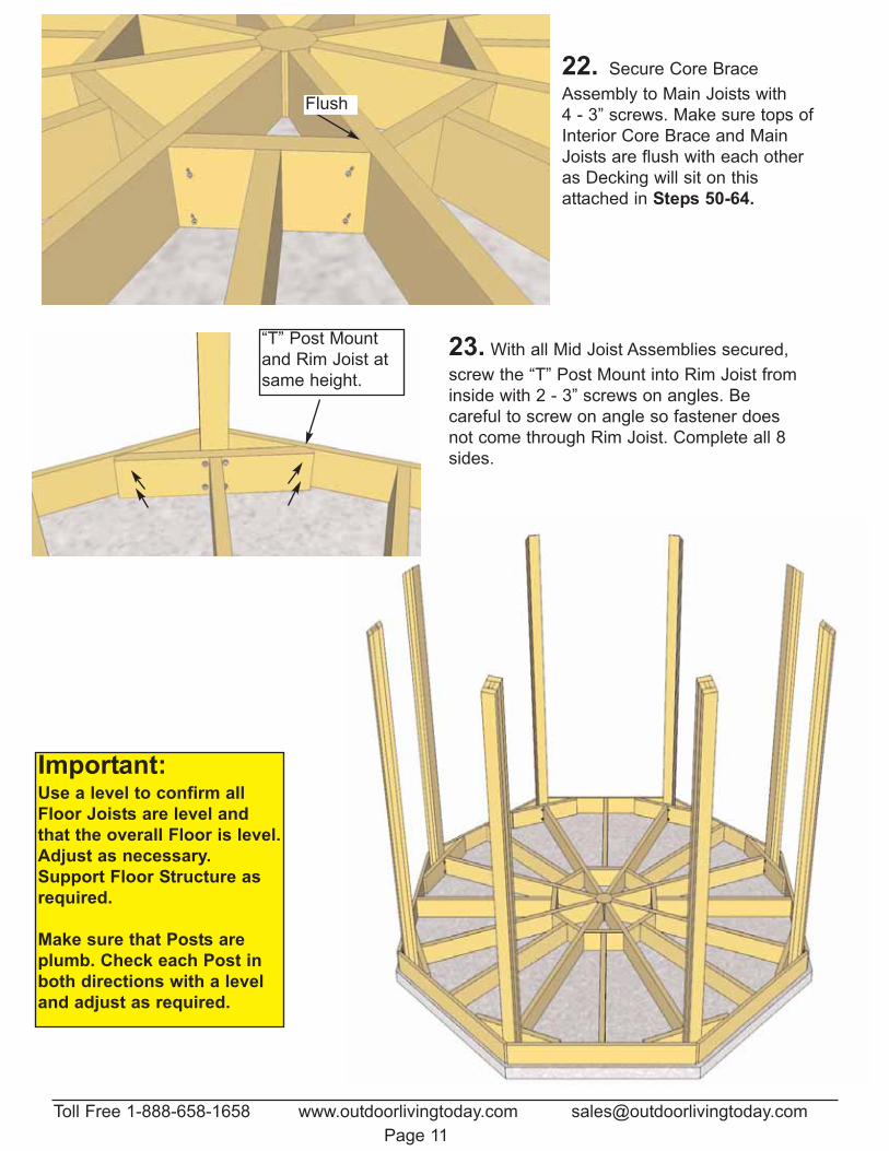
22. Secure Core BraceAssembly to Main Joists with 4 - 3” screws. Make sure tops ofInterior Core Brace and MainJoists are flush with each otheras Decking will sit on thisattached in Steps 50-64.
Flush
23. With all Mid Joist Assemblies secured,screw the “T” Post Mount into Rim Joist frominside with 2 - 3” screws on angles. Be careful to screw on angle so fastener doesnot come through Rim Joist. Complete all 8sides.
Important:Use a level to confirm allFloor Joists are level andthat the overall Floor is level.Adjust as necessary.Support Floor Structure asrequired.
Make sure that Posts areplumb. Check each Post inboth directions with a leveland adjust as required.
“T” Post Mountand Rim Joist atsame height.
Outdoor Living Today www.outdoorlivingtoday.com [email protected] 12
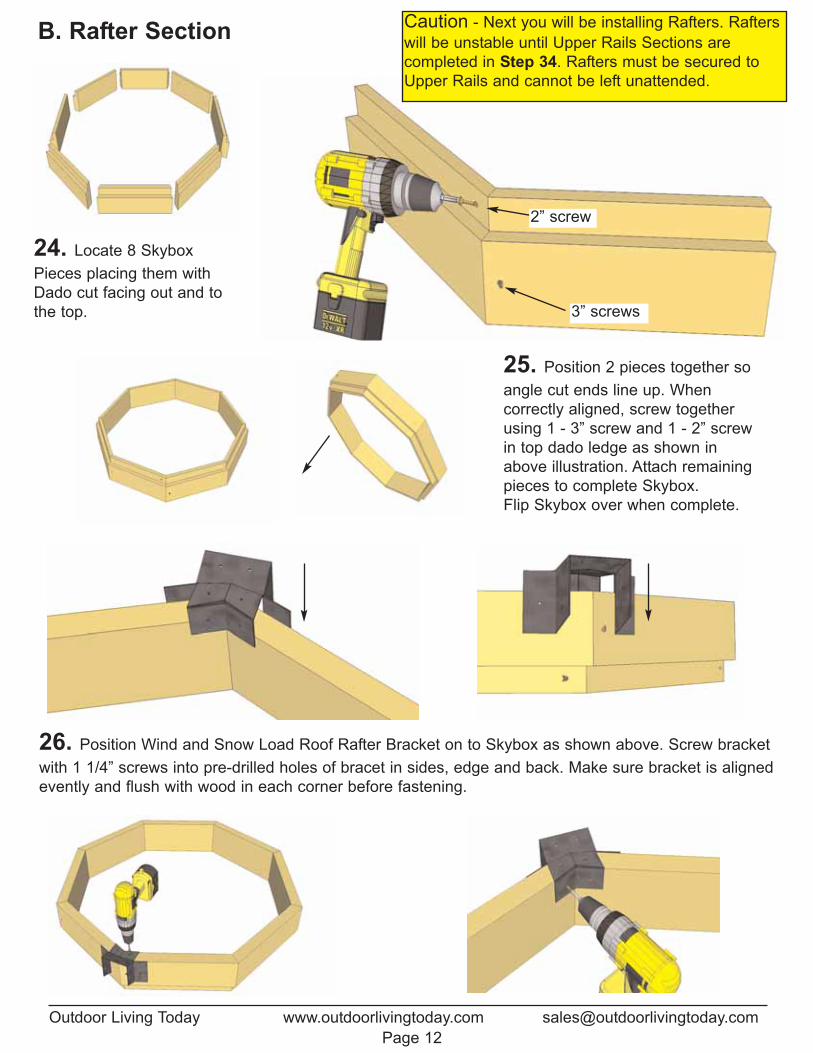
24. Locate 8 SkyboxPieces placing them withDado cut facing out and tothe top.
25. Position 2 pieces together soangle cut ends line up. When correctly aligned, screw togetherusing 1 - 3” screw and 1 - 2” screwin top dado ledge as shown inabove illustration. Attach remainingpieces to complete Skybox.Flip Skybox over when complete.
26. Position Wind and Snow Load Roof Rafter Bracket on to Skybox as shown above. Screw bracketwith 1 1/4” screws into pre-drilled holes of bracet in sides, edge and back. Make sure bracket is alignedevently and flush with wood in each corner before fastening.
B. Rafter Section
2” screw
3” screws
Caution - Next you will be installing Rafters. Rafterswill be unstable until Upper Rails Sections are completed in Step 34. Rafters must be secured toUpper Rails and cannot be left unattended.
Toll Free 1-888-658-1658 www.outdoorlivingtoday.com [email protected] 13
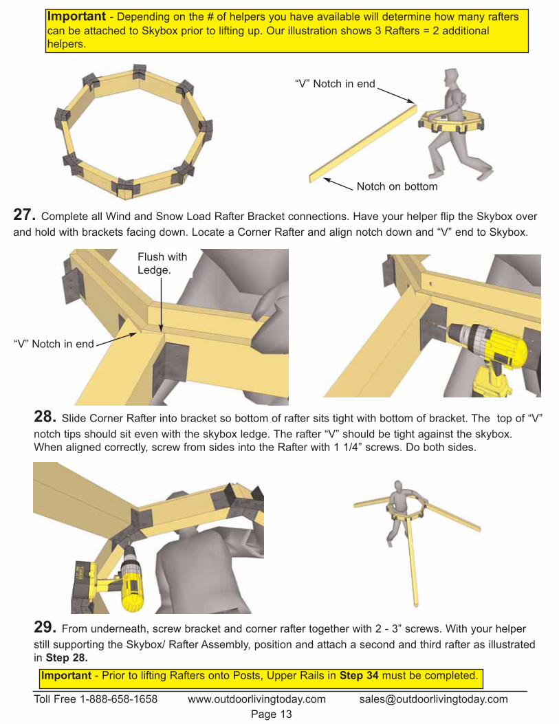
Important - Prior to lifting Rafters onto Posts, Upper Rails in Step 34 must be completed.
Important - Depending on the # of helpers you have available will determine how many rafterscan be attached to Skybox prior to lifting up. Our illustration shows 3 Rafters = 2 additionalhelpers.
27. Complete all Wind and Snow Load Rafter Bracket connections. Have your helper flip the Skybox overand hold with brackets facing down. Locate a Corner Rafter and align notch down and “V” end to Skybox.
28. Slide Corner Rafter into bracket so bottom of rafter sits tight with bottom of bracket. The top of “V”notch tips should sit even with the skybox ledge. The rafter “V” should be tight against the skybox.When aligned correctly, screw from sides into the Rafter with 1 1/4” screws. Do both sides.
Notch on bottom
Flush withLedge.
“V” Notch in end
“V” Notch in end
29. From underneath, screw bracket and corner rafter together with 2 - 3” screws. With your helperstill supporting the Skybox/ Rafter Assembly, position and attach a second and third rafter as illustratedin Step 28.
Toll Free 1-888-658-1658 www.outdoorlivingtoday.com [email protected] 14
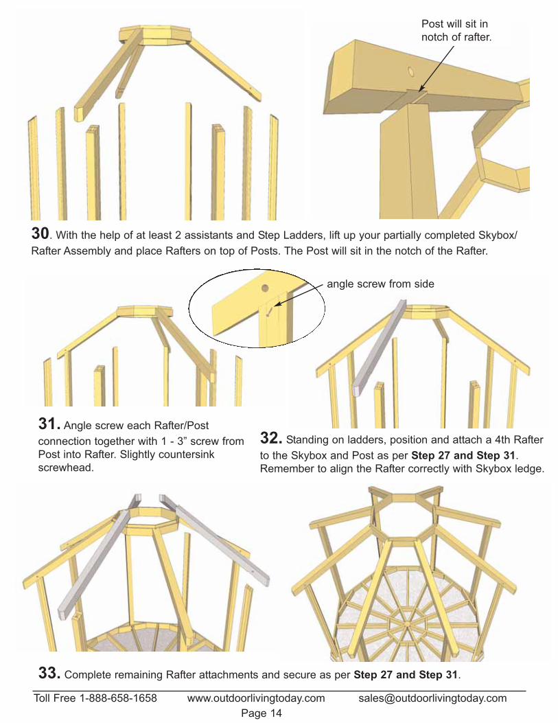
30. With the help of at least 2 assistants and Step Ladders, lift up your partially completed Skybox/Rafter Assembly and place Rafters on top of Posts. The Post will sit in the notch of the Rafter.
31. Angle screw each Rafter/Post connection together with 1 - 3” screw fromPost into Rafter. Slightly countersinkscrewhead.
33. Complete remaining Rafter attachments and secure as per Step 27 and Step 31.
Post will sit innotch of rafter.
32. Standing on ladders, position and attach a 4th Rafterto the Skybox and Post as per Step 27 and Step 31.Remember to align the Rafter correctly with Skybox ledge.
angle screw from side
Toll Free 1-888-658-1658 www.outdoorlivingtoday.com [email protected] 15
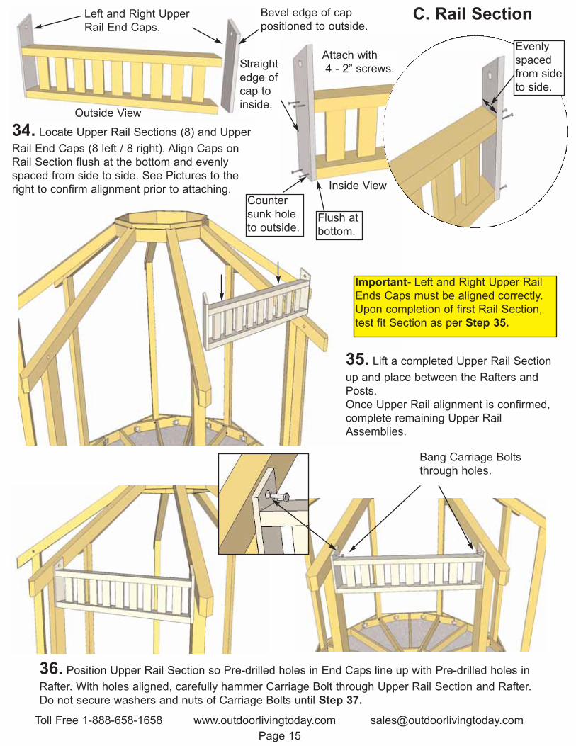
35. Lift a completed Upper Rail Sectionup and place between the Rafters andPosts. Once Upper Rail alignment is confirmed,complete remaining Upper RailAssemblies.
36. Position Upper Rail Section so Pre-drilled holes in End Caps line up with Pre-drilled holes inRafter. With holes aligned, carefully hammer Carriage Bolt through Upper Rail Section and Rafter.Do not secure washers and nuts of Carriage Bolts until Step 37.
Bang Carriage Boltsthrough holes.
Important- Left and Right Upper RailEnds Caps must be aligned correctly. Upon completion of first Rail Section,test fit Section as per Step 35.
C. Rail Section
34. Locate Upper Rail Sections (8) and UpperRail End Caps (8 left / 8 right). Align Caps onRail Section flush at the bottom and evenlyspaced from side to side. See Pictures to theright to confirm alignment prior to attaching.
Left and Right UpperRail End Caps.
Flush atbottom.
Evenlyspacedfrom sideto side.
Bevel edge of cappositioned to outside.
Countersunk holeto outside.
Outside View
Inside View
Attach with4 - 2” screws. Straight
edge of cap toinside.
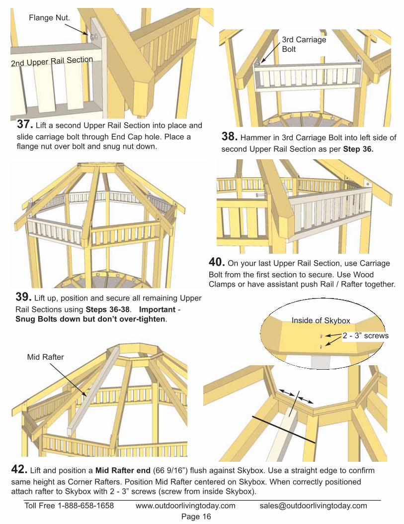
39. Lift up, position and secure all remaining UpperRail Sections using Steps 36-38. Important -Snug Bolts down but don’t over-tighten.
40. On your last Upper Rail Section, use CarriageBolt from the first section to secure. Use WoodClamps or have assistant push Rail / Rafter together.
38. Hammer in 3rd Carriage Bolt into left side ofsecond Upper Rail Section as per Step 36.
3rd CarriageBolt
42. Lift and position a Mid Rafter end (66 9/16”) flush against Skybox. Use a straight edge to confirmsame height as Corner Rafters. Position Mid Rafter centered on Skybox. When correctly positionedattach rafter to Skybox with 2 - 3” screws (screw from inside Skybox).
Mid Rafter
Inside of Skybox
2 - 3” screws
Toll Free 1-888-658-1658 www.outdoorlivingtoday.com [email protected] 16
37. Lift a second Upper Rail Section into place andslide carriage bolt through End Cap hole. Place aflange nut over bolt and snug nut down.
Flange Nut.
2nd Upper Rail Section
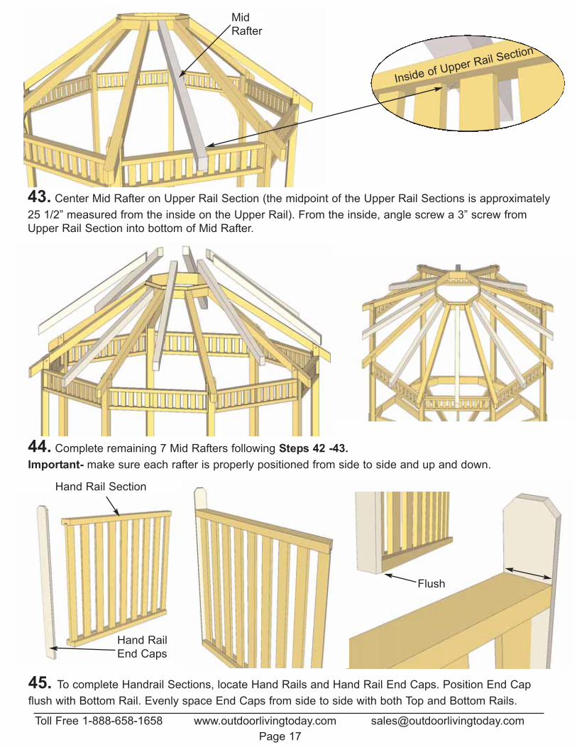
45. To complete Handrail Sections, locate Hand Rails and Hand Rail End Caps. Position End Capflush with Bottom Rail. Evenly space End Caps from side to side with both Top and Bottom Rails.
Flush
Hand Rail Section
Hand RailEnd Caps
44. Complete remaining 7 Mid Rafters following Steps 42 -43. Important- make sure each rafter is properly positioned from side to side and up and down.
43. Center Mid Rafter on Upper Rail Section (the midpoint of the Upper Rail Sections is approximately25 1/2” measured from the inside on the Upper Rail). From the inside, angle screw a 3” screw fromUpper Rail Section into bottom of Mid Rafter.
MidRafter
Inside of Upper Rail Section
Toll Free 1-888-658-1658 www.outdoorlivingtoday.com [email protected] 17
Toll Free 1-888-658-1658 www.outdoorlivingtoday.com [email protected] 18
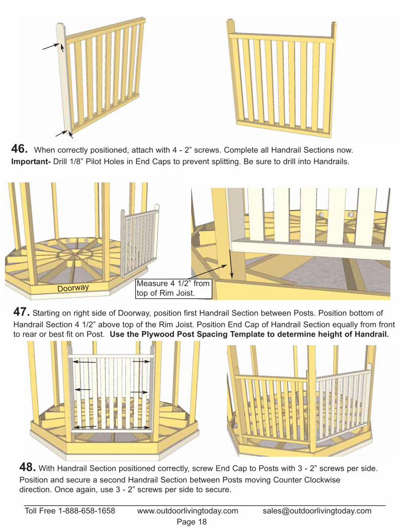
47. Starting on right side of Doorway, position first Handrail Section between Posts. Position bottom ofHandrail Section 4 1/2” above top of the Rim Joist. Position End Cap of Handrail Section equally from frontto rear or best fit on Post. Use the Plywood Post Spacing Template to determine height of Handrail.
48. With Handrail Section positioned correctly, screw End Cap to Posts with 3 - 2” screws per side.Position and secure a second Handrail Section between Posts moving Counter Clockwise direction. Once again, use 3 - 2” screws per side to secure.
Doorway Measure 4 1/2” fromtop of Rim Joist.
46. When correctly positioned, attach with 4 - 2” screws. Complete all Handrail Sections now.Important- Drill 1/8” Pilot Holes in End Caps to prevent splitting. Be sure to drill into Handrails.
Toll Free 1-888-658-1658 www.outdoorlivingtoday.com [email protected] 19
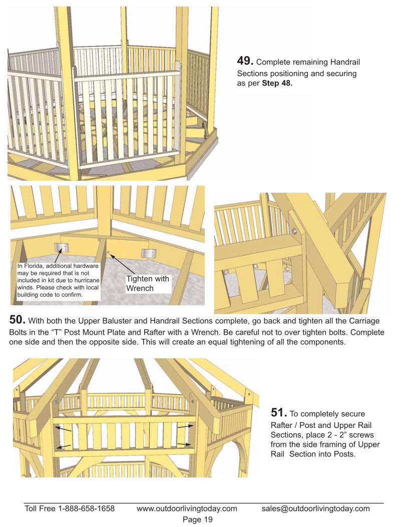
49. Complete remaining HandrailSections positioning and securingas per Step 48.
50. With both the Upper Baluster and Handrail Sections complete, go back and tighten all the CarriageBolts in the “T” Post Mount Plate and Rafter with a Wrench. Be careful not to over tighten bolts. Completeone side and then the opposite side. This will create an equal tightening of all the components.
Tighten withWrench
In Florida, additional hardwaremay be required that is notincluded in kit due to hurricanewinds. Please check with localbuilding code to confirm.
51. To completely secureRafter / Post and Upper RailSections, place 2 - 2” screwsfrom the side framing of UpperRail Section into Posts.
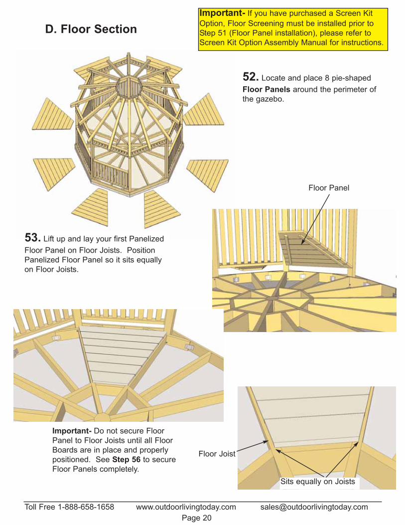
52. Locate and place 8 pie-shapedFloor Panels around the perimeter ofthe gazebo.
Floor Panel
53. Lift up and lay your first PanelizedFloor Panel on Floor Joists. PositionPanelized Floor Panel so it sits equallyon Floor Joists.
Sits equally on Joists
Floor Joist
Important- Do not secure FloorPanel to Floor Joists until all FloorBoards are in place and properlypositioned. See Step 56 to secureFloor Panels completely.
Toll Free 1-888-658-1658 www.outdoorlivingtoday.com [email protected] 20
D. Floor SectionImportant- If you have purchased a Screen KitOption, Floor Screening must be installed prior toStep 51 (Floor Panel installation), please refer toScreen Kit Option Assembly Manual for instructions.
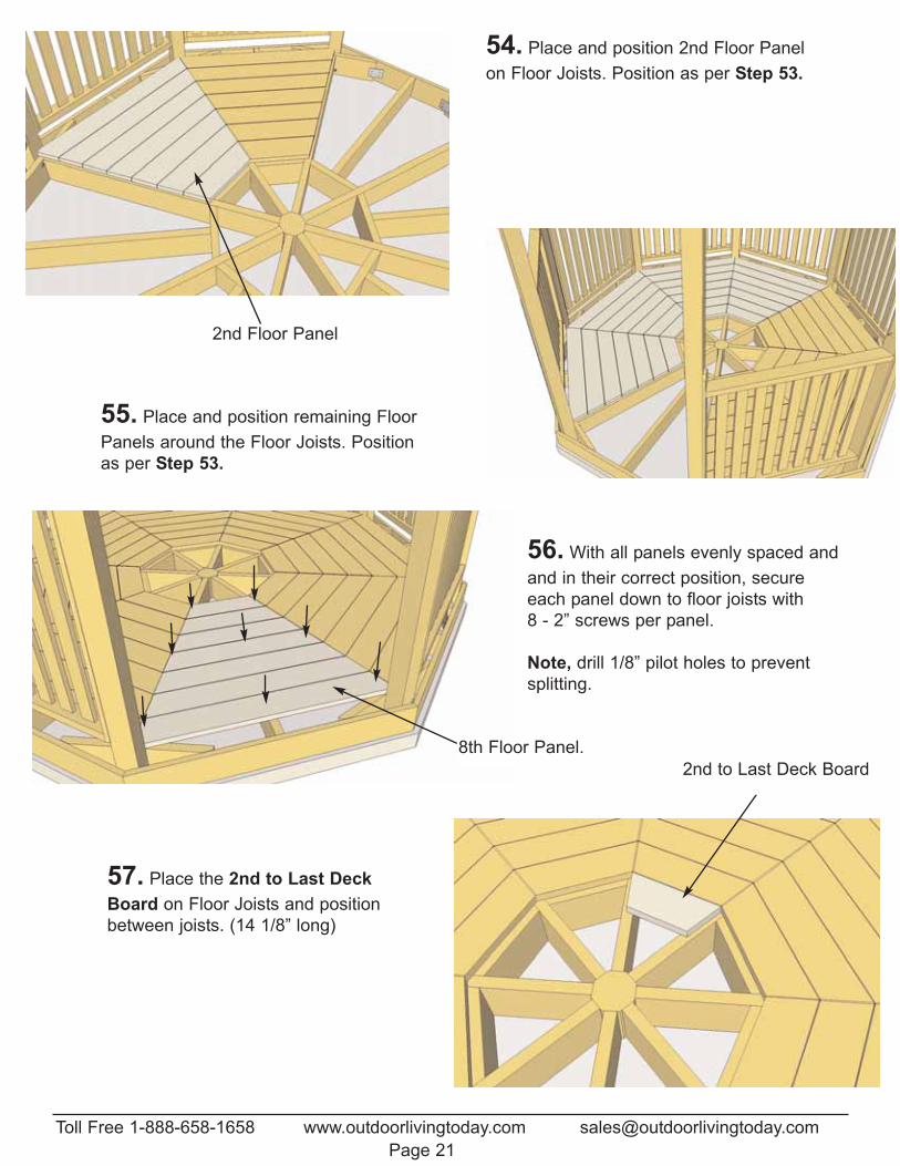
54. Place and position 2nd Floor Panelon Floor Joists. Position as per Step 53.
2nd Floor Panel
55. Place and position remaining FloorPanels around the Floor Joists. Positionas per Step 53.
8th Floor Panel.
56. With all panels evenly spaced andand in their correct position, secureeach panel down to floor joists with 8 - 2” screws per panel.
Note, drill 1/8” pilot holes to preventsplitting.
57. Place the 2nd to Last DeckBoard on Floor Joists and positionbetween joists. (14 1/8” long)
2nd to Last Deck Board
Toll Free 1-888-658-1658 www.outdoorlivingtoday.com [email protected] 21
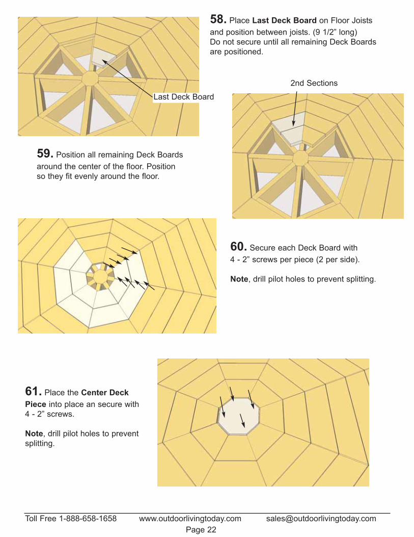
58. Place Last Deck Board on Floor Joistsand position between joists. (9 1/2” long)Do not secure until all remaining Deck Boardsare positioned.
Last Deck Board
59. Position all remaining Deck Boardsaround the center of the floor. Positionso they fit evenly around the floor.
2nd Sections
60. Secure each Deck Board with 4 - 2” screws per piece (2 per side).
Note, drill pilot holes to prevent splitting.
61. Place the Center DeckPiece into place an secure with4 - 2” screws.
Note, drill pilot holes to preventsplitting.
Toll Free 1-888-658-1658 www.outdoorlivingtoday.com [email protected] 22
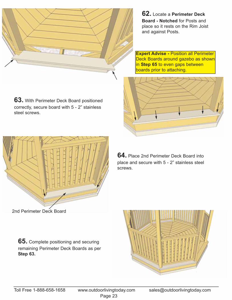
62. Locate a Perimeter DeckBoard - Notched for Posts andplace so it rests on the Rim Joistand against Posts.
63. With Perimeter Deck Board positionedcorrectly, secure board with 5 - 2” stainlesssteel screws.
64. Place 2nd Perimeter Deck Board intoplace and secure with 5 - 2” stainless steelscrews.
2nd Perimeter Deck Board
65. Complete positioning and securingremaining Perimeter Deck Boards as per Step 63.
Toll Free 1-888-658-1658 www.outdoorlivingtoday.com [email protected] 23
Expert Advise - Position all PerimeterDeck Boards around gazebo as shownin Step 65 to even gaps betweenboards prior to attaching.
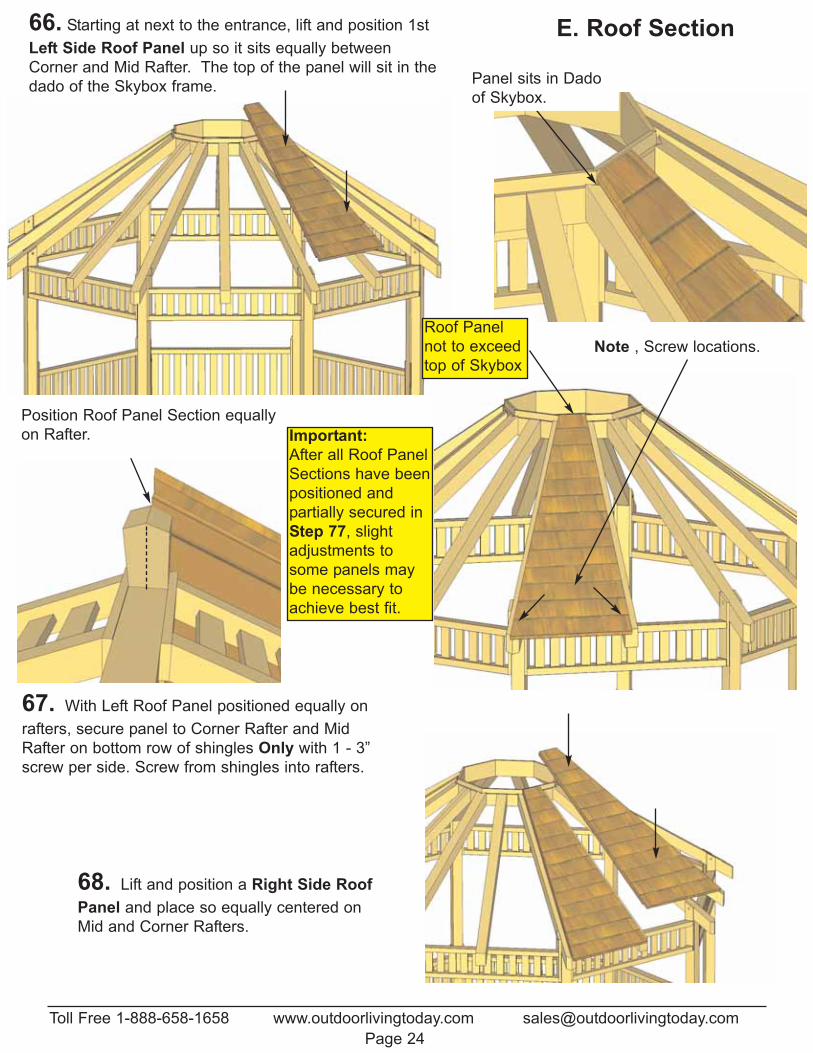
66. Starting at next to the entrance, lift and position 1stLeft Side Roof Panel up so it sits equally betweenCorner and Mid Rafter. The top of the panel will sit in thedado of the Skybox frame. Panel sits in Dado
of Skybox.
67. With Left Roof Panel positioned equally onrafters, secure panel to Corner Rafter and MidRafter on bottom row of shingles Only with 1 - 3”screw per side. Screw from shingles into rafters.
Position Roof Panel Section equallyon Rafter.
68. Lift and position a Right Side RoofPanel and place so equally centered onMid and Corner Rafters.
Note , Screw locations.
Toll Free 1-888-658-1658 www.outdoorlivingtoday.com [email protected] 24
E. Roof Section
Important:After all Roof PanelSections have beenpositioned and partially secured inStep 77, slightadjustments tosome panels maybe necessary toachieve best fit.
Roof Panelnot to exceedtop of Skybox
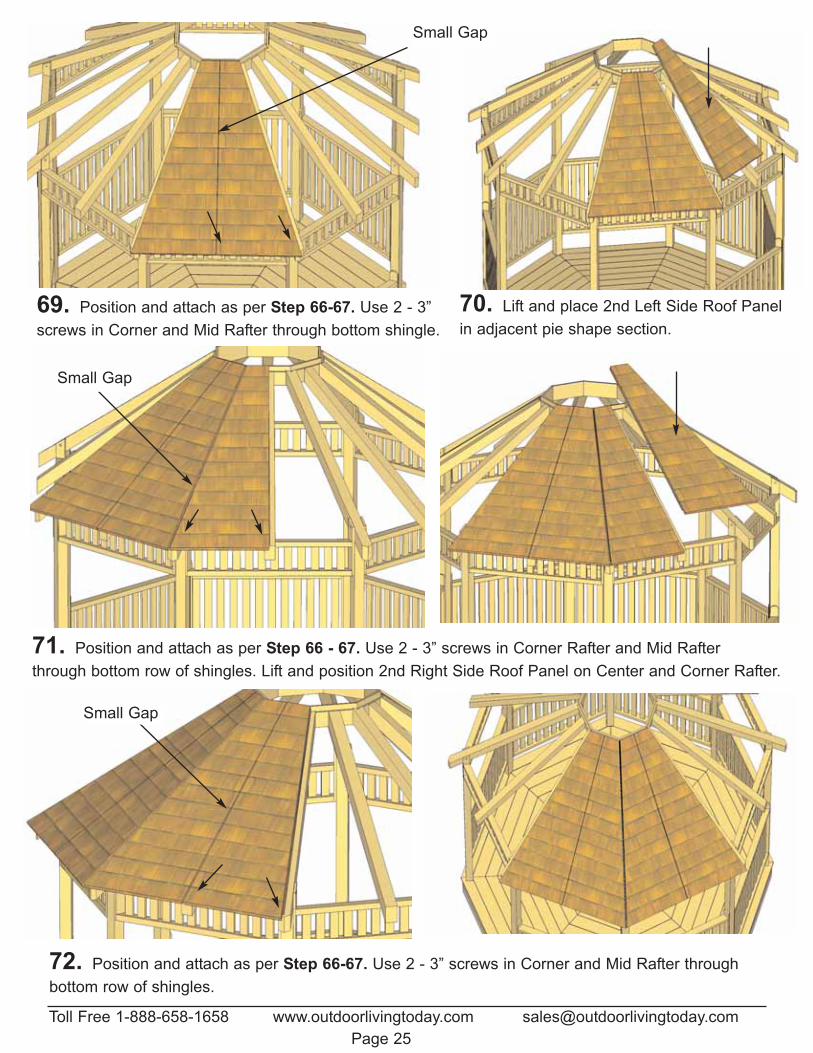
Small Gap
69. Position and attach as per Step 66-67. Use 2 - 3”screws in Corner and Mid Rafter through bottom shingle.
70. Lift and place 2nd Left Side Roof Panelin adjacent pie shape section.
71. Position and attach as per Step 66 - 67. Use 2 - 3” screws in Corner Rafter and Mid Rafter through bottom row of shingles. Lift and position 2nd Right Side Roof Panel on Center and Corner Rafter.
72. Position and attach as per Step 66-67. Use 2 - 3” screws in Corner and Mid Rafter throughbottom row of shingles.
Small Gap
Small Gap
Toll Free 1-888-658-1658 www.outdoorlivingtoday.com [email protected] 25
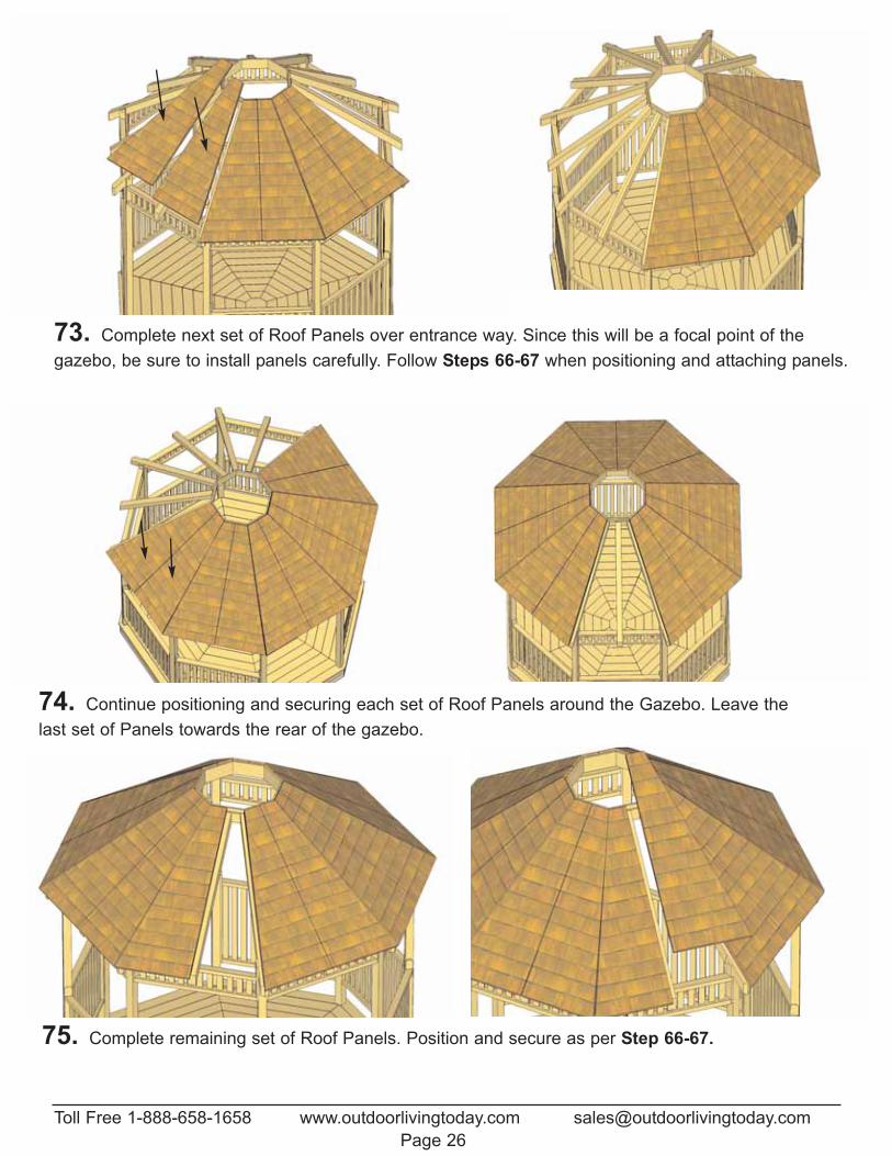
73. Complete next set of Roof Panels over entrance way. Since this will be a focal point of the gazebo, be sure to install panels carefully. Follow Steps 66-67 when positioning and attaching panels.
74. Continue positioning and securing each set of Roof Panels around the Gazebo. Leave thelast set of Panels towards the rear of the gazebo.
75. Complete remaining set of Roof Panels. Position and secure as per Step 66-67.
Toll Free 1-888-658-1658 www.outdoorlivingtoday.com [email protected] 26
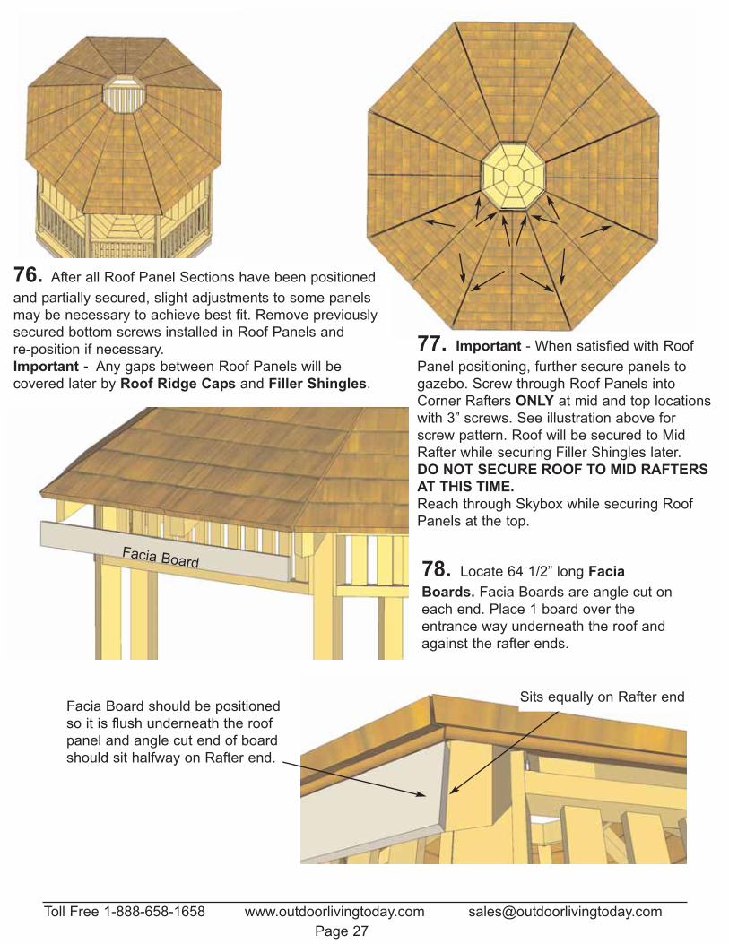
76. After all Roof Panel Sections have been positionedand partially secured, slight adjustments to some panelsmay be necessary to achieve best fit. Remove previouslysecured bottom screws installed in Roof Panels and re-position if necessary.Important - Any gaps between Roof Panels will be covered later by Roof Ridge Caps and Filler Shingles.
78. Locate 64 1/2” long FaciaBoards. Facia Boards are angle cut oneach end. Place 1 board over theentrance way underneath the roof andagainst the rafter ends.
Facia Board should be positionedso it is flush underneath the roofpanel and angle cut end of boardshould sit halfway on Rafter end.
77. Important - When satisfied with RoofPanel positioning, further secure panels togazebo. Screw through Roof Panels intoCorner Rafters ONLY at mid and top locationswith 3” screws. See illustration above forscrew pattern. Roof will be secured to MidRafter while securing Filler Shingles later. DO NOT SECURE ROOF TO MID RAFTERSAT THIS TIME.Reach through Skybox while securing RoofPanels at the top.
Sits equally on Rafter end
Toll Free 1-888-658-1658 www.outdoorlivingtoday.com [email protected] 27
Facia Board
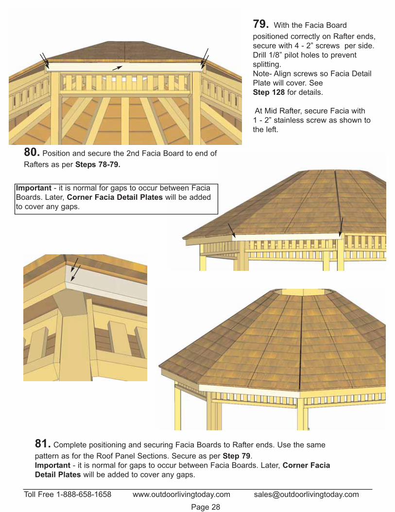
79. With the Facia Board positioned correctly on Rafter ends,secure with 4 - 2” screws per side.Drill 1/8” pilot holes to prevent splitting.Note- Align screws so Facia DetailPlate will cover. See Step 128 for details.
At Mid Rafter, secure Facia with 1 - 2” stainless screw as shown tothe left.
80. Position and secure the 2nd Facia Board to end ofRafters as per Steps 78-79.
81. Complete positioning and securing Facia Boards to Rafter ends. Use the same pattern as for the Roof Panel Sections. Secure as per Step 79. Important - it is normal for gaps to occur between Facia Boards. Later, Corner FaciaDetail Plates will be added to cover any gaps.
Toll Free 1-888-658-1658 www.outdoorlivingtoday.com [email protected] 28
Important - it is normal for gaps to occur between FaciaBoards. Later, Corner Facia Detail Plates will be addedto cover any gaps.
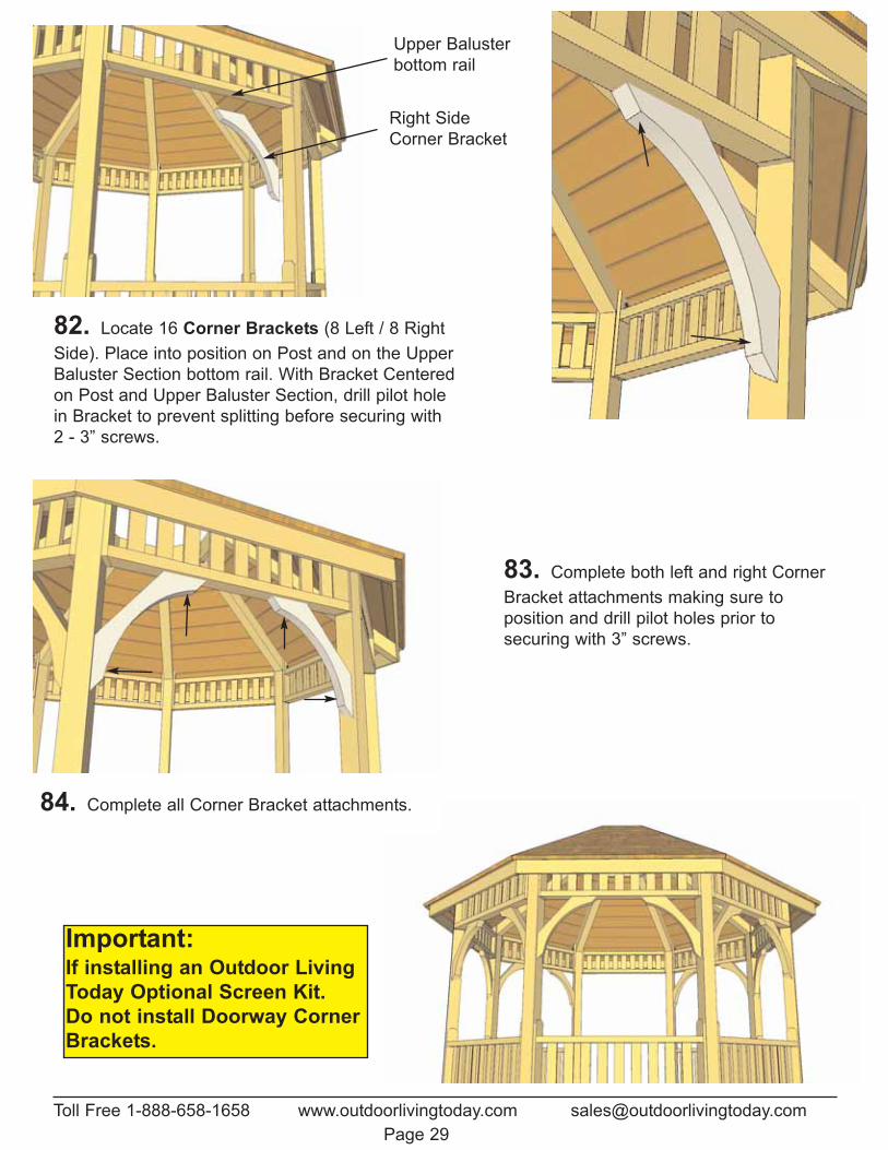
82. Locate 16 Corner Brackets (8 Left / 8 RightSide). Place into position on Post and on the UpperBaluster Section bottom rail. With Bracket Centeredon Post and Upper Baluster Section, drill pilot holein Bracket to prevent splitting before securing with 2 - 3” screws.
83. Complete both left and right CornerBracket attachments making sure to position and drill pilot holes prior to securing with 3” screws.
84. Complete all Corner Bracket attachments.
Right SideCorner Bracket
Upper Balusterbottom rail
Toll Free 1-888-658-1658 www.outdoorlivingtoday.com [email protected] 29
Important:If installing an Outdoor LivingToday Optional Screen Kit. Do not install Doorway CornerBrackets.
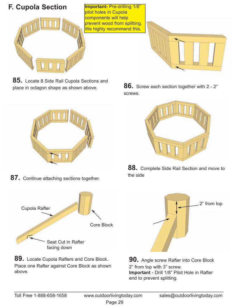
85. Locate 8 Side Rail Cupola Sections andplace in octagon shape as shown above. 86. Screw each section together with 2 - 2”
screws.
87. Continue attaching sections together.
88. Complete Side Rail Section and move tothe side
89. Locate Cupola Rafters and Core Block.Place one Rafter against Core Block as shownabove.
90. Angle screw Rafter into Core Block2” from top with 3” screw. Important - Drill 1/8” Pilot Hole in Rafterend to prevent splitting.
Core Block
Cupola Rafter2” from top
Seat Cut in Rafterfacing down
Toll Free 1-888-658-1658 www.outdoorlivingtoday.com [email protected] 29
F. Cupola Section Important- Pre-drilling 1/8”pilot holes in Cupola components will help prevent wood from splitting.We highly recommend this.
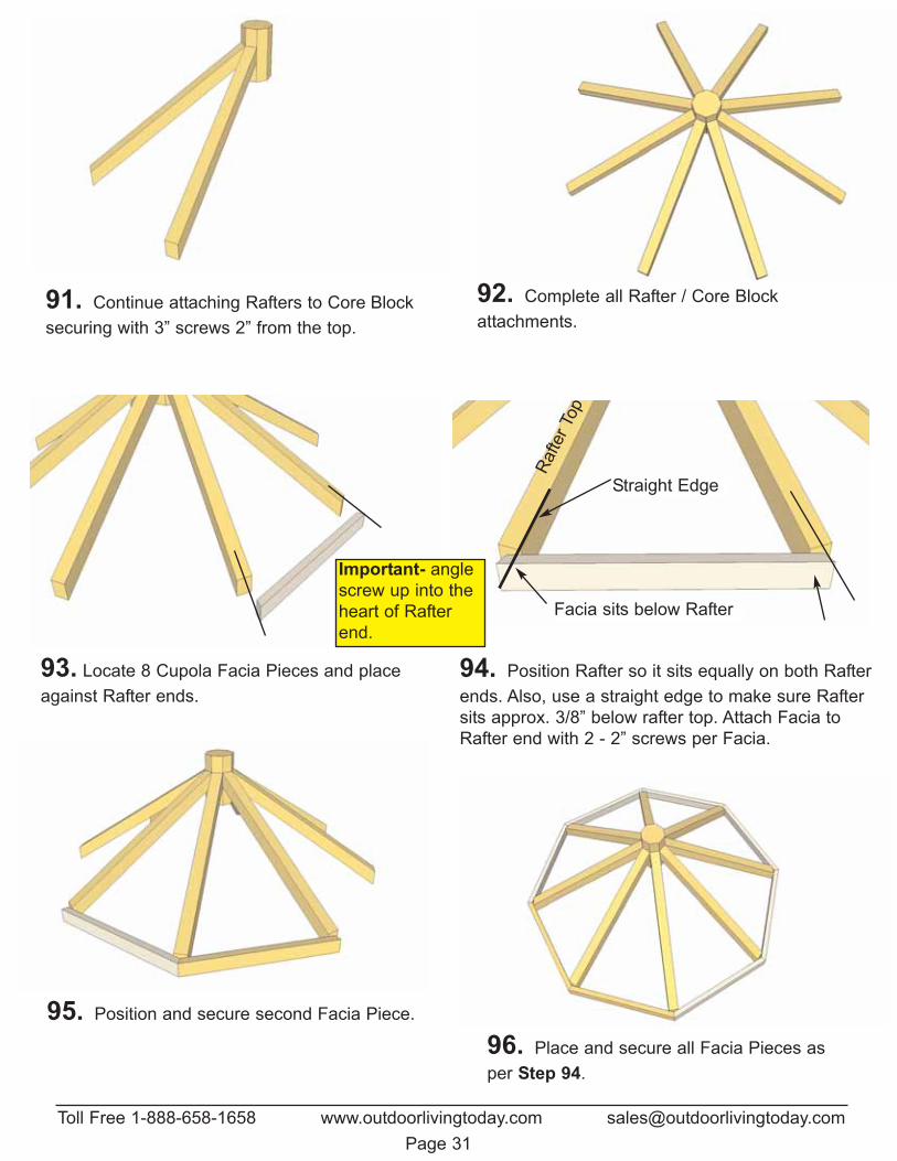
91. Continue attaching Rafters to Core Blocksecuring with 3” screws 2” from the top.
92. Complete all Rafter / Core Blockattachments.
93. Locate 8 Cupola Facia Pieces and placeagainst Rafter ends.
94. Position Rafter so it sits equally on both Rafterends. Also, use a straight edge to make sure Raftersits approx. 3/8” below rafter top. Attach Facia toRafter end with 2 - 2” screws per Facia.
95. Position and secure second Facia Piece.
96. Place and secure all Facia Pieces asper Step 94.
Straight Edge
Facia sits below Rafter
Rafte
r Top
Toll Free 1-888-658-1658 www.outdoorlivingtoday.com [email protected] 31
Important- anglescrew up into theheart of Rafterend.
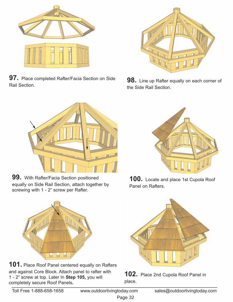
97. Place completed Rafter/Facia Section on SideRail Section.
98. Line up Rafter equally on each corner ofthe Side Rail Section.
99. With Rafter/Facia Section positioned equally on Side Rail Section, attach together byscrewing with 1 - 2” screw per Rafter.
100. Locate and place 1st Cupola RoofPanel on Rafters.
101. Place Roof Panel centered equally on Raftersand against Core Block. Attach panel to rafter with 1 - 2” screw at top. Later In Step 105, you will completely secure Roof Panels.
102. Place 2nd Cupola Roof Panel inplace.
Toll Free 1-888-658-1658 www.outdoorlivingtoday.com [email protected] 32
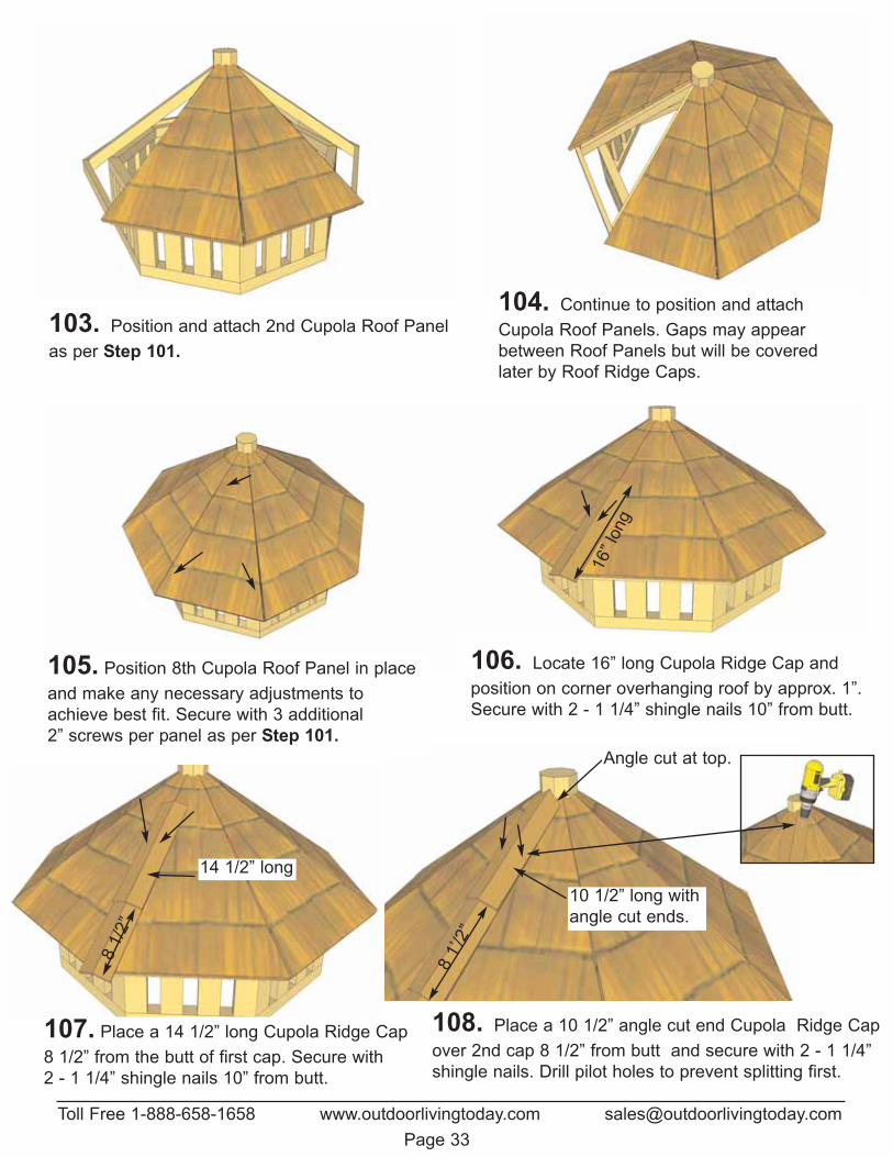
103. Position and attach 2nd Cupola Roof Panelas per Step 101.
104. Continue to position and attachCupola Roof Panels. Gaps may appearbetween Roof Panels but will be coveredlater by Roof Ridge Caps.
105. Position 8th Cupola Roof Panel in placeand make any necessary adjustments toachieve best fit. Secure with 3 additional 2” screws per panel as per Step 101.
106. Locate 16” long Cupola Ridge Cap andposition on corner overhanging roof by approx. 1”.Secure with 2 - 1 1/4” shingle nails 10” from butt.
107. Place a 14 1/2” long Cupola Ridge Cap8 1/2” from the butt of first cap. Secure with 2 - 1 1/4” shingle nails 10” from butt.
108. Place a 10 1/2” angle cut end Cupola Ridge Capover 2nd cap 8 1/2” from butt and secure with 2 - 1 1/4”shingle nails. Drill pilot holes to prevent splitting first.
Toll Free 1-888-658-1658 www.outdoorlivingtoday.com [email protected] 33
16” l
ong
81/
2”
81’/
2”
Angle cut at top.
14 1/2” long10 1/2” long withangle cut ends.
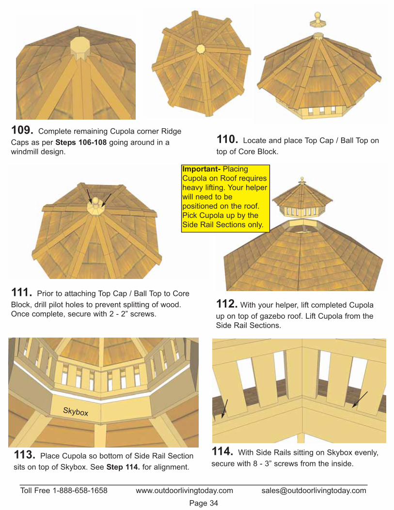
109. Complete remaining Cupola corner RidgeCaps as per Steps 106-108 going around in awindmill design.
110. Locate and place Top Cap / Ball Top ontop of Core Block.
111. Prior to attaching Top Cap / Ball Top to CoreBlock, drill pilot holes to prevent splitting of wood.Once complete, secure with 2 - 2” screws.
112. With your helper, lift completed Cupolaup on top of gazebo roof. Lift Cupola from theSide Rail Sections.
113. Place Cupola so bottom of Side Rail Sectionsits on top of Skybox. See Step 114. for alignment.
114. With Side Rails sitting on Skybox evenly,secure with 8 - 3” screws from the inside.
Skybox
Toll Free 1-888-658-1658 www.outdoorlivingtoday.com [email protected]
Important- PlacingCupola on Roof requiresheavy lifting. Your helperwill need to be positioned on the roof.Pick Cupola up by theSide Rail Sections only.
Page 34
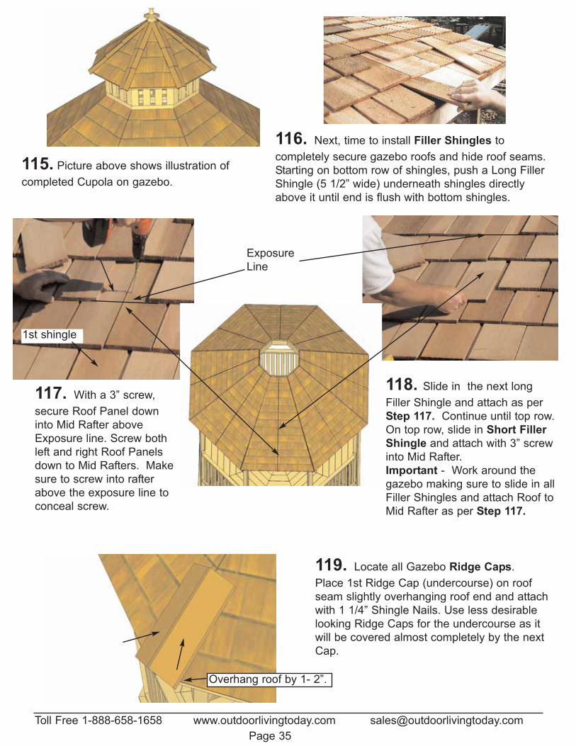
115. Picture above shows illustration of completed Cupola on gazebo.
116. Next, time to install Filler Shingles to completely secure gazebo roofs and hide roof seams.Starting on bottom row of shingles, push a Long FillerShingle (5 1/2” wide) underneath shingles directlyabove it until end is flush with bottom shingles.
117. With a 3” screw,secure Roof Panel downinto Mid Rafter aboveExposure line. Screw bothleft and right Roof Panelsdown to Mid Rafters. Makesure to screw into rafterabove the exposure line toconceal screw.
118. Slide in the next longFiller Shingle and attach as per Step 117. Continue until top row.On top row, slide in Short FillerShingle and attach with 3” screwinto Mid Rafter. Important - Work around thegazebo making sure to slide in allFiller Shingles and attach Roof toMid Rafter as per Step 117.
ExposureLine
119. Locate all Gazebo Ridge Caps. Place 1st Ridge Cap (undercourse) on roofseam slightly overhanging roof end and attachwith 1 1/4” Shingle Nails. Use less desirablelooking Ridge Caps for the undercourse as itwill be covered almost completely by the nextCap.
Toll Free 1-888-658-1658 www.outdoorlivingtoday.com [email protected] 35
1st shingle
Overhang roof by 1- 2”.
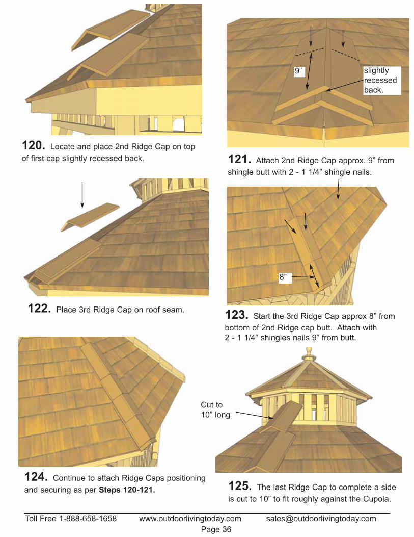
124. Continue to attach Ridge Caps positioningand securing as per Steps 120-121. 125. The last Ridge Cap to complete a side
is cut to 10” to fit roughly against the Cupola.
Cut to10” long
120. Locate and place 2nd Ridge Cap on topof first cap slightly recessed back. 121. Attach 2nd Ridge Cap approx. 9” from
shingle butt with 2 - 1 1/4” shingle nails.
122. Place 3rd Ridge Cap on roof seam. 123. Start the 3rd Ridge Cap approx 8” frombottom of 2nd Ridge cap butt. Attach with 2 - 1 1/4” shingles nails 9” from butt.
9”
8”
Toll Free 1-888-658-1658 www.outdoorlivingtoday.com [email protected] 36
slightlyrecessedback.
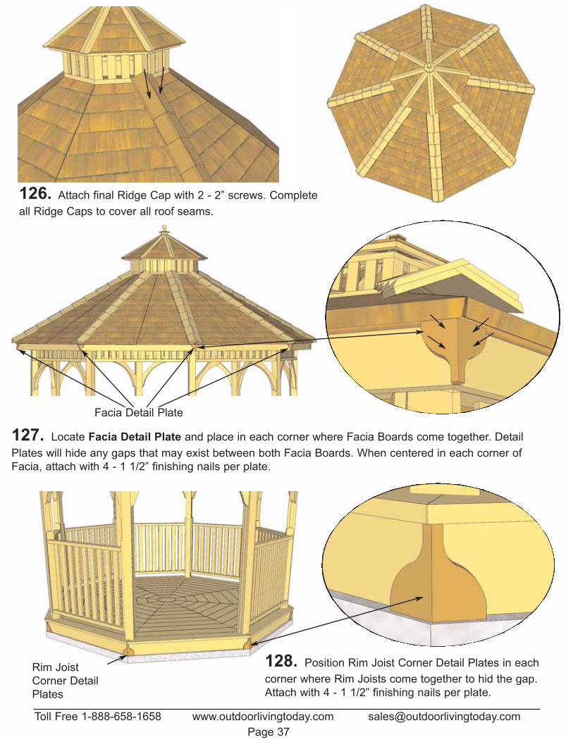
126. Attach final Ridge Cap with 2 - 2” screws. Completeall Ridge Caps to cover all roof seams.
Toll Free 1-888-658-1658 www.outdoorlivingtoday.com [email protected] 37
127. Locate Facia Detail Plate and place in each corner where Facia Boards come together. DetailPlates will hide any gaps that may exist between both Facia Boards. When centered in each corner ofFacia, attach with 4 - 1 1/2” finishing nails per plate.
Facia Detail Plate
128. Position Rim Joist Corner Detail Plates in eachcorner where Rim Joists come together to hid the gap.Attach with 4 - 1 1/2” finishing nails per plate.
Rim JoistCorner DetailPlates
Page 38
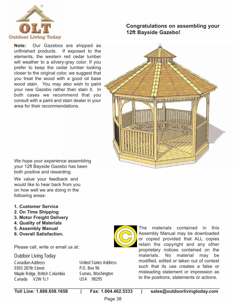
Congratulations on assembling your12ft Bayside Gazebo!
We value your feedback andwould like to hear back from youon how well we are doing in thefollowing areas:
1. Customer Service2. On Time Shipping3. Motor Freight Delivery4. Quality of Materials5. Assembly Manual6. Overall Satisfaction.
Toll Line: 1.888.658.1658 | Fax: 1.604.462.5333 | [email protected]
The materials contained in thisAssembly Manual may be downloadedor copied provided that ALL copiesretain the copyright and any other proprietary notices contained on thematerials. No material may be modified, edited or taken out of contextsuch that its use creates a false or misleading statement or impression asto the positions, statements or actions.
Canadian Address9393 287th StreetMaple Ridge, British ColumbiaCanada V2W 1L1
United States AddressP.O. Box 96Sumas, WashingtonUSA 98295
Outdoor Living TodayPlease call, write or email us at:
Note: Our Gazebos are shipped as unfinished products. If exposed to the elements, the western red cedar lumberwill weather to a silvery-gray color. If youprefer to keep the cedar lumber looking closer to the original color, we suggest thatyou treat the wood with a good oil basewood stain. You may also wish to paintyour new Gazebo rather than stain it. Inboth cases we recommend that you consult with a paint and stain dealer in yourarea for their recommendations.
We hope your experience assemblingyour 12ft Bayside Gazebo has beenboth positive and rewarding.