13 i torsion-flexure a prismatic member · 374 restrained torsion-flexure of prismatic member chap....
TRANSCRIPT
370
___wIC-
ENGINEERING THEORY OF PRISMATIC MEMBERS CHAP. 12
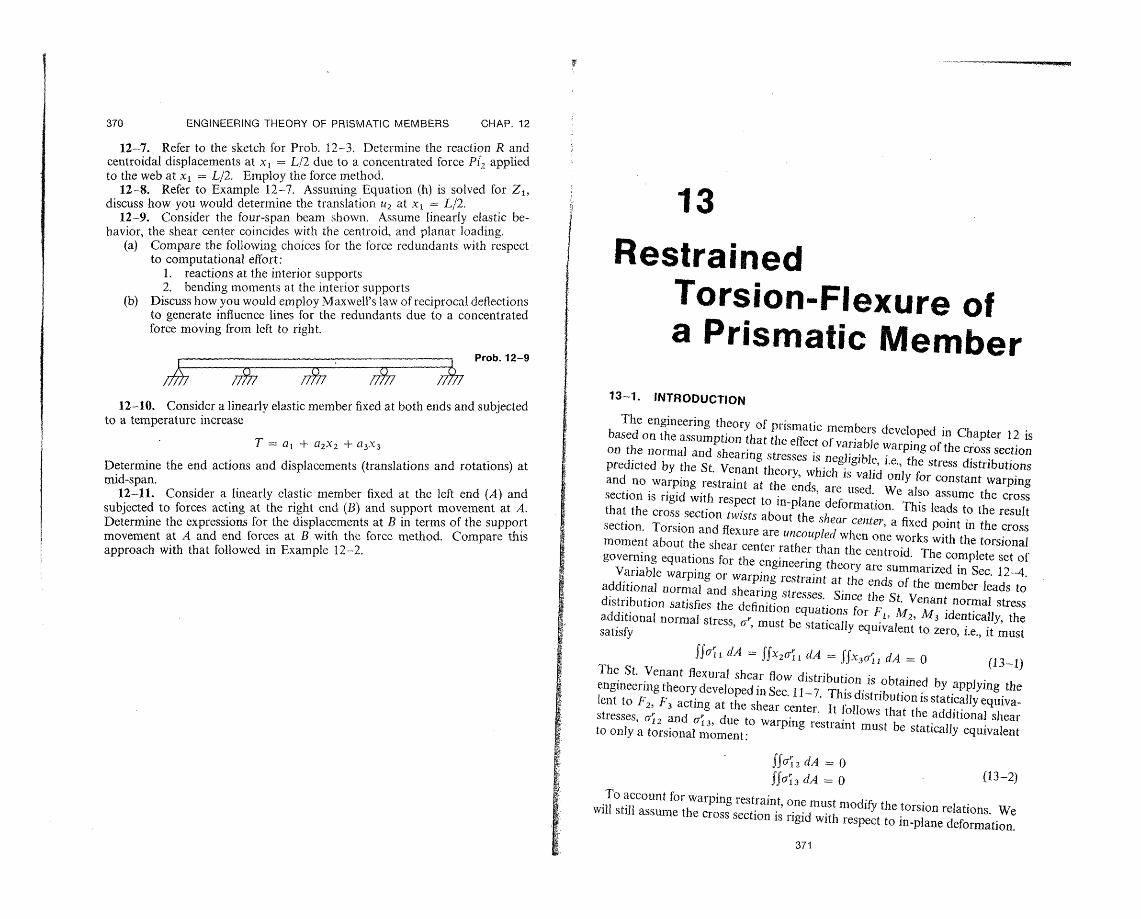
12-7. Refer to the sketch for Prob. 12-3. Determine the reaction R andcentroidal displacements at x = L/2 due to a concentrated force Pi2 appliedto the web at x = L/2. Employ the force method.12-8. Refer to Example 12-7. Assuming Equation (h) is solved for Z1,discuss how you would determine the translation u2 at x = L/2. 1312-9. Consider the four-span beam shown. Assume linearly elastic behavior, the shear center coincides with the centroid, and planar loading. I(a) Compare the following choices for the force redundants with respect
to computational effort: 1I Restrained1. reactions at the interior supports2. bending moments at the interior supports
(b) Discuss how you would employ Maxwell's law of reciprocal deflections Torsion-Flexure ofto generate influence lines for the redundants due to a concentrated force moving from left to right. a Prismatic Member
Dn,,. 4 a
."� n
/77 77* /7 13-1. INTRODUCTION12-10. Consider a linearly elastic member fixed at both ends and subjected
to a temperature increase The engineering theory of prismatic members developed in Chapter 12 isbased on the assumption that the effect of variable warping of the cross sectionT = a + a2x 2 + a3 x3 on the normal and shearing stresses is negligible, i.e., the stress distributionsDetermine the end actions and displacements (translations and rotations) at predicted by the St. Venant theory, which is valid only for constant warpingmid-span.12-11. Consider a linearly elastic member fixed at the left end (A) and
and no warping restraint at the ends, are used. We also assume the crosssection is rigid with respect to in-plane deformation. This leads to the resultsubjected to forces acting at the right end (B) and support movement at A. that the cross section twists about the shear center, a fixed point in the cross i
Determine the expressions for the displacements at B in terms of the supportmovement at A and end forces at B with the force method. Compare this section. Torsion and flexure are uncoupled when one works with the torsional
approach with that followed in Example 12-2. moment about the shear center rather than the centroid. The complete set ofgoverning equations for the engineering theory are summarized in Sec. 12-4.
Variable warping or warping restraint at the ends of the member leads toadditional normal and shearing stresses. Since the St. Venant normal stressdistribution satisfies the definition equations for F, 3I2, M3 identically, theadditional normal stress, a, must be statically equivalent to zero, i.e., it mustsatisfy
ffa' , dA f x2(,rrl I A = ' 3U',;, A = O (I i 18
The St. Venant flexural shear flow distribution is obtained by applying the
i! engineering theory developed in Sec. 11-7. This distribution is statically equivalent to F2, F3 acting at the shear center. It follows that the additional shear stresses, (o2 and a13, due to warping restraint must be statically equivalentto only a torsional moment:
R SfCr1 2 dA 0
(13-2)
To account for warping restraint, one must modify the torsion relations. Wewill still assume the cross section is rigid with respect to in-plane deformation.
371

--
C
372
373
:· i_ - CI-· sI·II·iWI-i~
RESTRAINED TORSION-FLEXURE OF PRISMATIC MEMBER CHAP. 13
In what follows, we develop the governing equations for restrained torsion. We start by introducing displacement expansions and apply the principle of virtual displacements to establish the force parameters and force-equilibrium equations for the geometrically linear case. We discuss next two procedures for establishing the force-displacement relations. The first method is a puredisplacement approach, i.e., it takes the stresses as determined from the strain (displacement) expansions. The second method is similar to what we employed for the engineering theory. We introduce expansions for the stresses in terms of the force parameters and apply the principle of virtual forces. This corresponds to a mixed formulation, since we are actually working with expansions for both displacements and stresses. Solutions of the governing equations for the linear mixed formulation are obtained and applied to thin-walled open and closed cross sections. Finally, we derive the governing equations for geomettrically nonlinear restrained torsion.
13-2. DISPLACEMENT EXPANSIONS; EQUILIBRIUM EQUATIONS
The principle of virtual displacementst states that
JffaT 3& d(vol.) = JffbT Au d(vol.) + 'fpT Au d(surface area) (a)
is identically satisfied for arbitrarydisplacement, Au, when the stresses (a) are in equilibrium with the applied body (b) and surface (p) forces. We obtain a system of one-dimensional force-equilibrium equations by introducing expansions for the displacements over the cross section in terms of one-dimensional displacement parameters. This leads to force quantities consistent with the displacement parameters chosen.
We use the same notation as in Chapters 11, 12. The X1 axis coincides with the centroid; X2, X3 are principal inertia axes; and x2, x3 are the coordinates of the shear center. We assume the cross section is rigid with respect to in-plane deformation, work with the translations of the shear center, and take the displacement expansions (see Fig. 13-1) as
l = ul + 2x3 - C) 3 X2 + f
a12 = Us2 - t)1(X3 - X3) (13-3) f13 = U3 + (O1(x2 - X2 )
where ¢ is a prescribed function of x2, X3, and
1. u1, us2, Us3 are the rigid body translations of the cross section. 2. 091, c02, (03 are the rigid body rotations of the cross section about the
shear center and the X2 , X 3 axes. 3. f is a parameter definining the warping of the cross section. The
variation over the cross section is defined by 4). Note that all seven parameters are functions only of x. For pure torsion
t See Sec. 10-6.
SEC. 13-2. DISPLACEMENT EXPANSIONS; EQUILIBRIUM EQUATIONS
(i.e., the St. Venant theory developed in Chapter 11), one sets f = o, = const and 0 = ,. For unrestrained variable torsion (i.e., the engineering theory developed in Chapter 12), one sets f = 0. Since there are seven displacement parameters, application of the principle of virtual displacements will result in seven equilibrium equations.
x3
1s3
- - -!. e9
/ Shear center tIs2
X2 1 1I
I -4(3 I X3 l
X27 2c
Centroid
Fig. 13-1. Notation for displacement measures.
The strain expansionst corresponding to (13-3) are
el = U1, + 0)2. 1X3 - C03, I2 + ft 1
E2 = 3 = 23 = 0
Y12 = Us2, 1 - 03 - 0)1. (X3 -- 3 ) + f 2
713 = U3, 1 + 092 + )1, (X2 - 2 ) + f, 3 (13-4)
Using (13-4), the left-hand side of(a) expands to
JfffrT ie d(vol.) = ,[F 1 Aul1, + F2(Auls2, 1 - A( 3)
+ F3(Aus3. 1 A) 2) + M2 A 2 , 1 + M3 A03 I (b) + MT Al, 1 + M Af 1 + MR Af]dx 1
where the two additional force parameters are defined by
M,= .Sll)dA (13-5)MR = (o12 ), 2 + 13 ¢0. 3)dA
Note that M, has units of (force) (length)2 and MR has units of moment. The quantity Ma is called the binoment.
t This derivation is restricted to linear geometry. The nonlinear strain expansions are derivedin Sec. 13-9.

374 RESTRAINED TORSION-FLEXURE OF PRISMATIC MEMBER CHAP. 13
To reduce the right-hand side of (a), we refer the transverse loading to the shear center. The additional load terms are
mo= ~fp,0 dS = distributed bimoment (13-6)
M, = Ip1 dA = external bimoment at an end section (xl1 0, L)
Then
JJJbT Au d(vol.) + SSpT Au d(surface area)
= J,,b 1 Au 1 + b2 Aus 2 + b A,3 3 mT A 1 + mi2 A92 (c) + m3 ACo3 + mO Af]dxl IF, Aul + F2 Au,2
MT2Ao + A0 2 + 1i3 A 3 + M, AfIx 1 =,L+ F 3 AU, 3 + ?M
1j, MT are the same as for the engineeringThe definitions of bj, mj, mT, Fj, MVtheory.
Finally, we equate (b), (c) and require the relation to be satisfied for arbitrary variations of the displacement parameters. This step involves first integrating
(b) by parts to eliminate the derivatives and then equating the coefficients of the displacement parameters. The resulting equilibrium equations and boundary conditions are as follows:
Equilibrium Equations
F1, + bl = 0 F2, 1 + b2 = 0
F3, 1 + b3 = 0
MT, 1 + mT = 0
M2, I - F3 + m2 = 0
M3 ,1 + F2 + m3 = 0
M¢,l- MR + m, = 0
Boundary Conditionsat xl = 0 (13-7)
ul = 11 or F1 = -Ft
Us2 s2 o=or F2 = -F2
U,3 =Uis3 ' or F 3 = -F 3
cot = l or MT = -MT
°(2 = 2 or M2 = -M2
(03 = (3 or M3 = -/M3
f = f or MO= Pld
Boundary Conditions at x = L
These are the same as for xI = 0 with the minus sign replaced with a plus sign.
For example: f = f or MO = +M,
SEC. 13-3. DISPLACEMENT MODEL 375
We recognize the first six equations as the governing equations for the engineering theory. The additional equation,
M¢,t - MR + m = 0 0 < x < L (d)
f = f or M = T M, x = O,L
is due to warping restraint. Also, we see that one specifies either f or the bimoment at the ends of the member. The condition f = f applies when the end cross section is restrained with respect to warping. If the end cross section
is free to warp, the boundary condition is M = Me (+ for x = L).
To interpret the equation relating MR and the bimoment, we consider the definition for MR,
MR = Jf(o'1 2 , 2 + c1 305 3)dA (e)
Integrating (e) by parts leads to
M, = p, ¢b dS - (Ul12 ,2 + a1 3, 3)dA (f)
Utilizing the axial stress equilibrium equation,
+ 0'13.3 + 1 1O1 2 , 2 ,. 1 = (g) we can write
MR = P 1 dS + f0all, dA (h)
= rns + Ml, I
We see that (h) corresponds to the axial equilibrium equations weighted with respect to ,
SS(a 1 2, 2 + U1 3 , 3 + l 1 ,1)0 dA + (P - n 2 a1 2 - c,43 13 )40 dS = 0
(i) M ,, 1 + m- MR = 0
In most cases, there is no surface loading on S, i.e., pi = 0 on the cylindrical boundary. We will discuss the determination of stresses in a later section. We simply point out here that MR involves only the additionalshear stresses due to warping restraint since the St. Venant shearing stresses correspond to
alt = .t
13-3. FORCE-DISPLACEMENT RELATIONS-DISPLACEMENT MODEL
To establish the relation between force parameters and the displacement parameters, we consider (13-4) to define the actual (as well as virtual) strain distribution and apply the stress-strain relations. We also consider the material to be isotropic and suppose there is no initial strain. The stress expansions are
a11 = Eeffl =' Eeff[ul, 1 + X3(02,1- X2(0 3, 1 + f 115]
01 2 = G 1 2 = G[us2 , 1 - 03 - (l, 1 (X - 3) + f¢, 2] (13-8)3
C13 = Gy 1 3 = G[Us3, 1 + (02 + 01 1(X2 - 2 ) + f4, 3]
t MR = M, = 0 for St. Venant (pure) torsion. We neglect MR and M .forunrestrained variable torsion.

--
376 377 RESTRAINED TORSION-FLEXURE OF PRISMATIC MEMBER CHAP. 13
where E, denotes the effective modulus. Although our displacement expansionscorrespond to plane strain ( 2 = E3 = 0), the in-plane stresses vanish on the boundary. Therefore, it seems more reasonable to use the extensional stressstrain relations for plane stress. In what follows, we will take E,, = Young's modulus, E.
Consider the expression for ral1. The term involving 4)is due to warping of the cross section. This additional stress must satisfy (13-1), which, in turn,requires to satisfy the following orthogonality conditions:'1
Jft dA = ix 2 0 dA = ffx30 dA = (13-9)
Assuming (13-9) is satisfied, and noting that X2, X3 are principal centroidal axes, the expressions for F1, M2, M 3, and the M, reduce to:
F - EAul, l
M 2 = E 2C 2, (13-10)M 3 = E13 03. 1
M = Elcf I1where
=I,.F dA We have included the subscript r on E to keep track of the normal stress due
to warping restraint. Inverting (13-10) and then substituting in the expression for a 1l lead to
r-l -I 2 .x3 -- x2 + M d (13-11)Theexpressions, MT, andfor F, expand to
The expressions for F 2, F 3, MT, and MR expand to
1IF 2 = A(us2, 1 - (03 + X'3C0)1, 1) + fS2
1-l F3 = A(us3, 1 (02 2 01. 1) + fS 3
1 G = 11(0, + f,
(13-12)
M = M + x 3 F2 - 2F3
1 S2 S3. G MR = -2 + G F23 + ,0,1 + f
where Si ='Jdj dA It = polar moment of inertia = 2 + I3 IQ = (X2, 3 - X30, 2)dA
I = ( 2 + )d - - (S + S)
t F1 = M M3 = for a, due to warping restraint.
SEC. 13-3. DISPLACEMENT MODEL
Also, the expressions for the shearing stresses canbe written as
F['12
F2- G -- X3)I,1 f , 2 --8'2"1
A 3 (13-13)
A A
The essential step is the selection of q0 which, to this point, must satisfy onlythe orthogonality conditions (13-9). To gain some insight as to a suitable form for , let us reexamine the St. Venant theory of unrestrained torsion. We suppose the section twists about an arbitrary point (x, x'), instead of about the centroid as in Sec. 11-2. The displacement expansions are
U2 = -o 1 (x 3 - x3) U3 = 0l(X - x2)2 (a)I =- c. 1,l;i
where w0), = M 1 /GJ = const. Operating on (a) leads to
M. r12- M 2 - (X3 - X3)]
(b)
(J13 J id,3 + (X2 - x-2)J
The equation and boundary condition for t', follow from the axial equilibriumequation and boundary condition,
V2 =o 0 in A
; --WI-a= (Xn2(X3 x3) - a3(X2 X'2) on S (c)
We can express t' as
= C - xx 2 + x2x 3 + t, (d) where C is also an arbitrary constant. The boundary condition and expressions for the stresses become
gin - n2 3 - n3X2
t 2 A (t, 2 - X3) (e)
13 = Ml (0t,3 + X2 )i
Since At depends only on the cross section, it follows that the stress distribution

--
----
378 379
RESTRAINED TORSION-FLEXURE OF PRISMATIC MEMBER CHAP. 13
and torsional constant are independent of the center of twist. Also, one can showt that
2J t, 3 dA = 0 (f)5, 2 A = Wff- I(x20, 3 - 3QS,2)dA = fj[(t.2)2 + (t, 3)2]dA
Suppose we take = . The constants (C, x, x'3) are evaluated by requiring 4t to satisfy (13-9), and we obtain
C = A o dA
X = 1
jx I2
3 0)t dA (g)
1 x3I =IJX 2 t dA
13
Now, one can showl that the equations for x', x'y are identicalto the equations for the coordinates of the shear center when the cross section is considered to
be rigid with respect to in-plane deformation. That is, the warping function for unrestrained torsion about the shear center is orthogonal with respect to
1, x2, X3. Summarizing, we have shown that
4 = C - 3 x + 2-X 3 + 4)t = t (13-14) 2
is a permissible warping function. The cross-sectional properties and forcedisplacement relations corresponding to this choice for 4)are listed below:
Cross-SectionalProperties
S2 = - 3 A S3 = +X 2A
; = -i'1 (13-15) J = I1 + I = I, - I
= 2)2 + ()t, 3 )2 ]dA2J[((,
Shear Stresses
Cr12 F2 + G(-X3o) 1,1 + f)t, 2)
(13-16)
t3 = 3-F+ G(X2(9 1, + f t, 3)""
t See Sec. 11-2 and Prob. 11-2. $ See Prob. 13-1.
SEC. 13-4. RESTRAINED TORSION-DISPLACEMENT MODEL
Force-DisplacementRelations
MT = GIco1, - Galf + x 3F2 - 2F3
MR = GI(f - ()1, ) - 3F2 + -x2F 3
F2GA- Us 2, I - (3 - 3 (f - C, 1) (13-17)GA
F3GA =
u s 3, 1 + cO2 + - 2 (f - )1, 1)
We introduce the assumption of negligible restraint against warping by setting Er, = 0. Then, MOy = 0, and the seventh equilibrium equation reduces to MR =. Specializing (13-17) for this case, we obtain
f - 1 = I (- 3 F2GI" - x2F3 ) (13-18)
MT = GJCoI,
and
Us 2 , = C03 F2 -
-x20:F3 +
F, / X2X3
us3, = 2 F2
+ -G( + 3 ( x 2F2 )
(13-19)
I- ± 9 I
The shearing stress distributions due to F2, F3 do not satisfy the stress boundary condition
0n2 '12 + On 3 G1 3 O on S (a)
However, one can show that they satisfy
;(a.2r + (On3rl3 )dS = 0 (b)1 2 2
for arbitrary F 2, F3. Equations (13-19) are similar in form to the results obtained in Chapter 12, which were based on shear stress expansions satisfying (a) identically on the boundary.
Finally, we point out that torsion and flexure are uncoupled only when warping restraint is neglected (E, = 0). Equations (13-17) show that restrained torsion results in translation of the shear center. We will return to this point in the next section.
13-4. SOLUTION FOR RESTRAINED TORSION-DISPLACEMENT MODEL
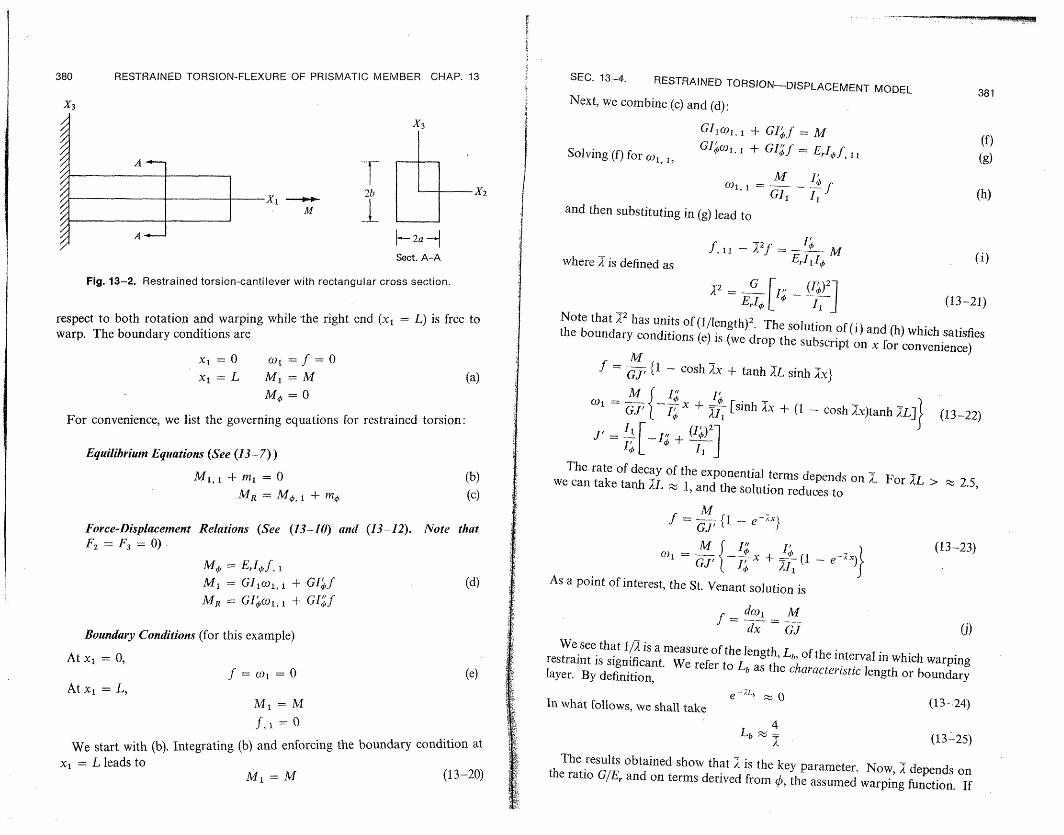
To obtain an indication of the effect of warping restraint, we apply the theory developed in the previous section to a cantilever member having a rectangular cross section. (See Fig. 13-2). The left end (xl = 0) is fixed with
��'' :�_-~-""~\~sa�aaaAnxmg�m�J��
380 RESTRAINED TORSION-FLEXURE OF PRISMATIC MEMBER CHAP. 13 SEC. 13-4. RESTRAINED TORSION-DISPLACEMENT MODEL 381
X3 Next, we combine (c) and (d):
X3 GIcol, 1 + GIf = M (f)
///////////
Solving (f) for 1 , GI c 1 + GIf = Eof (g) l
///////
I 1 2b I
jW)1,'1 M -I I 1=fij
! X1 nd then substitutiGI (h)I
M and then substituting in (g) lead to
-2aH- I/ f, 1 -2f _= MSect. A-A (i)where is defined as Edl 1¢
Fig. 13-2. Restrained torsion-cantilever with rectangular cross section. 2 = G l,, ()2 (13-21)
respect to both rotation and warping while the right end (x = L) is free to Note that 12 has units of(l/length) 2. The solution of(i) and (h) which satisfieswarp. The boundary conditions are the boundary conditions (e) is (we drop the subscript on x for convenience) x =0 Wot =f=O f = GJ {1 - cosh Ax + tanh ZL sinh x}x = L M 1 =M (a)
M, = 0
For convenience, we list the governing equations for restrained torsion:
I cosh)tanh (1 L]} (13-22)
2J ... ,i- + (-)qEquilibriumEquations(See (13-7))
M1, 1 + m = 0 (b) The rate of decay of the exponential terms depends on A. For XL >we can take tanh L 1, and the solution reduces to
2.5, MR = M, + mO (c)
M -
Force-Displacement Relations (See (13-10) and (13-12). Note that f=- i{1 -e }
F2 = F3 = 0) c1 = Ga{ ( 7x ' + (1 e
(13-23) -Me, EriE,f,
M1= Glcwl, + GI'f (d) As a point of interest, the St. Venant solution is MR = GIECol,1 + GIf
dotl M
Boundary Conditions (for this example) dx GJ (j)
We see that 1/1 is a measure of the length, L,, of the interval in which warpingAt x1 = 0, restraint is significant. We refer to Lb as the characteristiclength or boundary0f = ol = (e) layer. By definition, At x = L,
M =M In what follows, we shall take (13-24)
f, = 0 Lb (13-25)
We start with (b). Integrating (b) and enforcing the boundary condition (13-25)
at xI = L leads to The results obtained show that is the key parameter. Now, depends on
= M (13-20) the ratio G/Er and on terms derived from , the assumed warping function. If

F
er~
SEC. 13-5. MIXED FORMULATION 383
382 RESTRAINED TORSION-FLEXURE OF PRISMATIC MEMBER CHAP. 13 The translations of the shear center follow from (13-17):
we take 4) = 4c, the warping functiont for unrestrained torsion defined by U,2, 1 = x3(f - CO0,x) I
(13-14), the various coefficients are related by (13 26 Us3, 1 = - 2 (f - 01 ,x) (13-30)
r, 1 -- . (13-26) By definition, the translations are zero at the center of twist. Setting f2l = 3 = IJ,-II -I, 0 in (13-3) and letting x, x3 denote the coordinates of the center of twist [a __ T
lead to
At this point, we restrict the discussion to a rectangular section (see Fig. 13-2) x2 = X2 x5 = g3
(13-31)and 4) =4)c. We evaluate the various integrals defined by (13-15) and write 11 = 1 -1UI~(1 e-X
the results as . = K,a3 b g x 'I
We see that the center of twist approaches the shear center as x increases. TheI_ - + Kga3 b (13-27) maximum difference occurs at x = 0 and the minimum at x = L. I = K1a3 b
1 I,Io = Koa3 b3
v - K - Kh rJ ; - 1 .- W d n'tions, he 1 --
(13-32)=where the K's are dimensionless functions of b/a. With these definitions, the qjX~~~~L
/r-\1/2 1 glx=l -!expression for a takes the form
= 3 ) K -b (13-28) __ 1
fKK)
I For unrestrained warping, E, = 0, = co, and g = 1. KK(1--- 11-
13-5. FORCE-DISPLACEMENT RELATIONS-MIXED FORMULATION is essentialy
We first review briefly the basic variational principles for the three-dimen-The coefficients are tabulated in Table 13-1. We see that K h
constant. Assuming E 2.6G and K, z 3.2, we find 2/b and Lb 2b. sional formulation. The principle of virtual displacements requires
The influence of warping restraint is confined to a region of the order of the 1.
abtdepth Alhough this result was derived for a rectangular cross section, we wi to'b' d(vol.) = fb r Au d(vol.) + fSprAu d(surface area) (a)
show later that it is typical of solid and also thin-walled closed cross sections. to be satisfied for arbitrary Au and leads to the stress-equilibrium equations
Table 13-1 and stress-boundary force relations. Note that 6; is a function of Au and is
obtained using the strain-displacement relations. The stress-strain relations b
K, K¢, K, K1 can be represented as
., ...... a £' 66 = V* (b)
since, by definition of the complementary energy density,1 2.25 .0311 .156 3.36 2 3.66 .165 .450 3.16 r3V* aV* 3 4.21 .283 .683 3.23 ei(q) - yij(g) " (c)
10 4.99 .425 .964 3.32 ((07ii auij
twist. We utilize the By combining (a) and (b), we obtain a variational principle which leads to both
We consider next the problem of locating the center of I; sets of equations. The stationary requirement,
solution corresponding to = ) and large 7L: b[ff((TE - Tu - V*)d(vol.) - SfpTu d(surface area)] = 0 (13-33)
M -} (13-29) considering a, u as independent quantities, = (u), and , b prescribed, is
_ -- ._1 eX} called Reissner's principle.t
C(1 GJ- 1 e t See Ref. 11 and Prob. 10-28. Reissner's principle applies for arbitrary geometry and elastic
material. This discussion is restricted to linear geometry. The nonlinear case is treated in Sec. 13-9.
reduces to t C- YZ - 0 for a rectangular section and h

384 RESTRAINED TORSION-FLEXURE OF PRISMATIC MEMBER CHAP. 13 SEC. 13-5. MIXED FORMUI ATInKi 385The essential point to recognize is that Reissner's principle allows one to The first procedure (based on (13-34)) is more convenient since it avoidswork with a and u as independent quantities. In a displacement formulation introducing the equilibrium equations. However, one has to have the strain-(Sec. 13-3), we take a as a function of u, using the stress-displacement relations
= D = u(u), and aTh - V* reduces to V, the strain-energy density. In a displacement relations. In certain cases, e.g., a curved member, it is relatively
mixed formulation we start by introducing expansions for the displacements.The Euler equations for the displacement parameters are obtained by ex- MTpanding (a). This step leads to the definition of force parameters and force-
-8Mr ,- 7 S__
equilibrium equations. We then generate expansions for the stresses in terms -6Mx, dx1 8M + 6&VIdxl
X1of the force-parameters from an equilibrium consideration. The relations WCll + COldxbetween the force and displacement parameters are obtained from the second f f+f,ldxlstationary requirement:
fXI,[J(T bg - V*)dA]dxl = (13-34) Fig. 13-3. Virtual force system. The first step was carried out in Sec. 13-2 and the expanded form off ETra dA easy to establish the force-equilibrium equations by applying the euilibriumis given by (b) of Sec. 13-2. Letting V* represent the complementary energy
per unit length along X1 , and using (13-4), the stationary requirement on the conditions to a differential element. We obtain the force-displacement relations
stresses (Equation 13-34) expands to by applying the second procedure (principle of virtual forces) without having to introduce strain expansions.t
3Flu, + F2(us2, -- 03) + F3(ts, 3, 1 + cO2) + M 2o2, 1 In what follows, we consider the material to be homogeneous, linearly elastic + &M3 )3, M + MToll + M4 .f, 1 + 6MRf - (5cV* = and isotropic. To simplify the treatment, we also suppose there is no initial
In order to proceed further, we must express VF in terms of the force parameters strain. The complementary energy density is
(F1, F2, ... , MR). Equating the coefficients of each force variation to zero results in the force-displacement relations. Jj a 11 IA + ' (12 + f2 3 )dA2E% ~ _E 1 2 13/L (13-36)Instead of applying (13-34), one can also obtain (13-35) by applying the principle of virtual forces to a differential element. We followed this approach It remains to introduce expansions for the stress components in terms of thein Chapter 12 and, since it is of interest, we outline the additional steps required force parameters such that the definition equations for the force parametersfor restrained torsion. One starts with (see Fig. 13-3) are identically satisfied.
cbV* dx, = dl, P, = [.ffu 3p dA]x, + CUT (p dA],,+dX, (a) Considering first the normal stress, we can write +
The boundary forces are the stress components acting on the end faces. Taking i F, M, Mu according to (13-3) and considering only MT, M,, MR, we have i aI + X3 - t2 + - 0
ff 6pTU dA = ff I (a)
dA hiTu = ±(6MTo 1 + 6M f) tU)
where ¢ satisfies the orthogonality conditions: §
where the plus sign applies for a positive face. The virtual-force system must dA =ffX30 dA 0 (b)ffO dA = ffx- 2 dbe statically permissible, i.e., it must satisfy the one-dimensional equilibrium
equations. This requires Note that we have imposed a restriction on . The complementary energy
(MT = const due to o expands to
d (c)dx (M) = Mn + I ~M2
Then, dxl + g , (V)T1: 2.E - 2 i3 (c)
t The approach based on the principle of virtual forces is not applicable for the eometicallvL di P dxl {f M f v M + 1 M4 (d) nonlinear case.
d M 1, I 5 MT} +See (13-1 i). Problem 13-8 treats the case of a nonhomogeneous material.=dx1(f Ir1 MI f ff +
=F = 2 M 3 =0for o,, due to warping restraint.

386
387
II ----------·-��-�L�··�.�ex78�n�i�Yi��iB�w
RESTRAINED TORSION-FLEXURE OF PRISMATIC MEMBER CHAP. 13
Finally, substituting for (V*),,i in (13-35), we obtain
F1 M2 U1, -- A 02, =--
(d)MK3 M,/,
603, 1 --EI3 f, 1 - ,i
Ejo,
These expansions coincide with the corresponding relations obtained with the displacement model (see (13-10)).
The shearing stress distribution must satisfy the definition equations forF2, F3, MT and MR identically. We can obtain suitable expansions by addinga term due to warping restraint to the results for unrestrained torsion and flexure. We write
0 3j =l + ij + a'i (13-37)
where 0ai is the flcexural distribution due to F2, F3; o/-j is the unrestrained torsion distribution; and u-lj is the distribution due to restrained torsion.
Since we are assuming no in-plane deformation, the fexural distribution for a thin-walled section can be obtained by applying the engineering theorydeveloped in Sec. 11-7. For a solid section, we utilize the results of Sec. 11-5,taking v = 0.
The shear stress distribution for unrestrained torsion is treated in Sees. 11-2through 11-4. Since the restrained-torsion distribution is statically equivalentto a torsional moment, we have to distinguish between the unrestrained and restrainedtorsional moments:
MT = M'. + Mi
(13-38) olj = f(M)
It remains to determine cri. We follow the same approach as in the engineering theory of flexural shear stress, i.e., we utilize the axial equilibriumequations and stress boundary condition:
012, 2 + 13, 3 - 1, 1 in A
2 1 2 + n3 013 = 0 on S (a)
anZ
Differentiating the expression for all and noting the equilibrium equations, we obtain
F2 F3 MR (b)
13 12 14
Since af satisfies (a) for arbitrary F2, F3 and a" corresponds to al = 0, it follows that ar is due to MR:
o 2, 2 - 013 3 - - M (in A)I, (13-39)
aXn2U12 + Cn3CT 1 3 - 0 (on S)
SEC. 13-5. MIXED FORMII ATInnr
The orthogonality conditions on 0 and boundary condition on or ensure thatt rr- - _ .
==jo`2 dA 0 F3 = ft' dA = 03 ... _̂.}d_v (13-40)We solve (13-39) and then evaluate M'" from
-Myp = [SI (X3 - Xa)- 12 + ( - X 2) 3JdA (c)1
Noting (13-40), we see that MT = M'. Finally, we write (c) as
MI = + CMR I I2_A1l
Iwhere C is cross-sectionalpreyhhenowhere C, is a cross-sectional property awhich depends on o.Wthsfio, With this definition,
M = M +CbMR (1 A -A-Or.t
When the cross section is thin-wailed, we neglect l,, and (a) reduces to
17 s, = - 1,
a, = 0 ·. at a free edare (d) We take and o-; to be constant over the thickness t and work with the shear flow q = o-,t. Equation (d) becomes
q, s = -- '' t (13-43)
qr =0 at a free edge
The orthogonality conditions on and boundary condition on q ensure that
F = fcs 2 q (IS = 0
F'3 = f3q'd]S = (13-44)
Finally, we determine C, by evaluating MS and equating to (13-41). We consider next the complementary energy density.
form of the shear contribution as We write the expanded
V'shEear=̀G i (Or2 + (7'2 + ('12)2 (f3 + 03 1t 3)2
IdA
r/.= V7 + P, Sr 'P I vf1(5 t/*f,FM ++ T + +, -t V~~~~~~~~~.1 (13-45)
We have evaluated Pj-, ,* and V/,, in Sec. 11-5. For convenience, theseresults are summarized below (See Equation 11-98)
2I S2 2F2F3 ff)_VI= G
1.- -3 + -,, A ,
V* - (7)- (a)2 GJ *Puf= o
f(See Prob. 13-2.
388
389
RESTRAINED TORSION-FLEXURE OF PRISMATIC MEMBER CHAP. 13
n axis of symmetry.section hasnThe coupling term, 1/A 23, vanishes when the
Also Vu*f 0 is a consequence of our assuming the cross
respect to in-plane deformation. We evaluate V, using (13-39) ((13-43) for the thin-walled case), and write
the results as .I 2 I r.... I(13-4b)1 E(c'2) + (6f 3)
2
2dATi Mf 13-b
* = 261 [(,ri~)2 + (o)i]
ed aswhere C, is a dimensionless factor which depends on 4). The coupling between unrestrained and restrained torsion is express,
V,, = f (2'12i12 + 9t3613)dA -GGJ MATMR (13-47)
ur -7:; JJj ton since " is an odd
It is obvious that Cur =0 for a thin-walled open section since c is an odd I
function of n whereas r * is constant over the. thickness. We will show later
that it is possible to make C,, vanish for a closed section by specializing the
homogeneous solution of (13-43). Therefore, in what follows, we will take
Cr= , we write the coupling b fura and res0.trained torsion a Finally, we write the coupling between flexural and restrained torsion as
;= (al + a3ai3)dVr GjI (13-48)
1Cfl (X3,F12MR + X2 rF3MR)
since 6 .xjhave units of length. If X2 is an axis of symmetry, X3 =
where is symmetrical and or is antisymmetrical with respect to the X2 axis.
+ C,IR, and equateWe substitute for V*in (13-35), replace MTr with AMT
the coefficients of 6F2, (5F3, M, and 3MR. The resulting force-displacement
relations are .I -- + M
Uls2, 1 - (03 (t
3, F02 A+ J MrF3
Us3, 1 + 2 G A23 (13-49)
C, -I + x2 F3)CC l' M ' 6J(X3 r 2 x_,.3)
given by (13-12).The corresponding relations for the displacement model are
Up to this point, we have required 4)to satisfy the orthogonality relations
and also determined a' such that there is no energy coupling between 6U and
r (C,, = 0). If, in addition, we take
) = -(C - x 3 x2 +-X2x 3 + el)= -0C
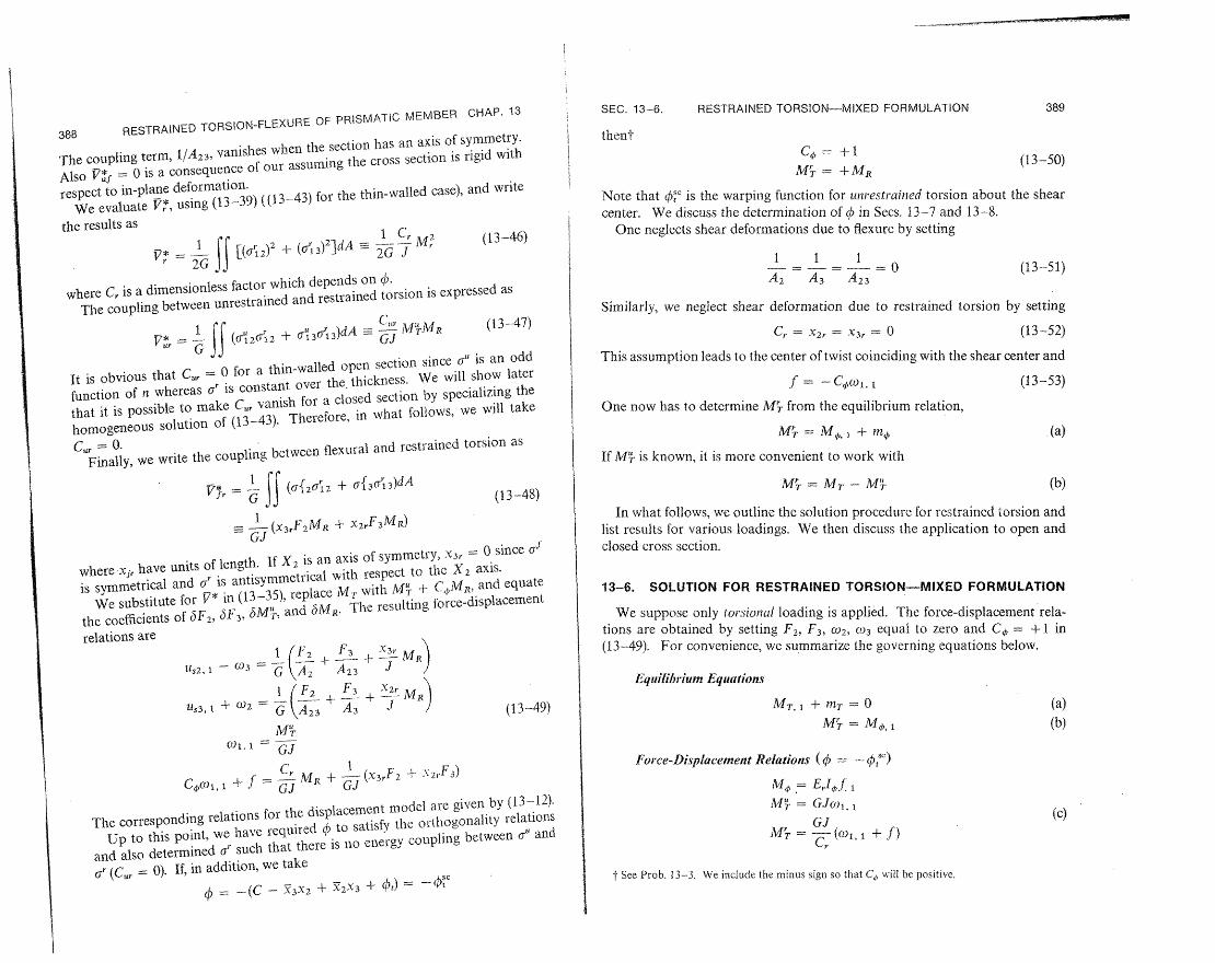
SEC. 13-6. RESTRAINED TORSION-MIXED FORMULATION
thent C,= +1
(13-50)M'T = + MR
Note that )c'is the warping function for unrestrainedtorsion about the shear We discuss the determination of b in Sees. 13-7 and 13-8.
center. One neglects shear deformations due to flexure by setting
1 1 1 (13-51)
A, A3 A23
Similarly, we neglect shear deformation due to restrained torsion by setting
G , -X2,- X3r = (13-52)
This assumption leads to the center of twist coinciding with the shear center and
f = -Col, (13-53)
One now has to determine M'T from the equilibrium relation,
-M = M, 1 + mn .(a)
If M'- is known, it is more convenient to work with
MT = MT - M' (b)
In what follows, we outline the solution procedure for restrained torsion and list results for various loadings. We then discuss the application to open and
closed cross section.
13-6. SOLUTION FOR RESTRAINED TORSION-MIXED FORMULATION
We suppose only torsional loading is applied. The force-displacement rela+ 1 in
tions are obtained by setting F 2, F3, C02, 0)3 equal to zero and C,* =
(13-49). For convenience, we summarize the governing equations below.
Equilibrium Equations
MTlT1 M~T = (a) (b)
Force-DisplacementRelations ( = - S,")
M = E f 1
MT = GJO1, 1 (c)
GJ M = -C. (co, + f)
XSee Prob. l3--3. We include the minus sign so that Ca will be positive.

-sEs
SEC. 13-6. RESTRAINED TORSION-MIXED FORMULATION 391
CHAP. 13390 RESTRAINED TORSION-FLEXURE OF PRISMATIC MEMBER
The significance of Adhas been discussed in Sec. 13-4. We should expect,
Boundary Conditions on the basis of the results obtained there, that XL will be large with respect
MT or W prescribed at each end (d) to unity for a closed section. We will return to the evaluation of Ain the next
section. In the examples below, we list for future reference the solution for M or f various loading and boundary conditions.
Translations of the Shear Center C--lri 1-1 -B Illllll[ C I t
(e) U,2,1 - GJ Us3, i GJ
Cantilever-Concentrated MomentGJT
We start by integrating (a): Fig. E13-1
MT = C1 - nT dx = C + MTp(13-54)
Substituting (c) in (b) and (13-54) leads to the governing equations for col and f: -X1 M
(1 + Cr)(oll + f- G, (C1 + MTp) (f)
C,ErIf.tl- GJ(wl, + f) = 0 L- -
After some manipulation, (f) becomes
Ero 1 +Cx + - IMTp dl. The boundary conditions (Fig. El3-1) are f ICI - f-G, GJ
+ C G j (g)GJ x ='O Wo = f = 0
= L MT=M (a) where- f =sid f.x 0
where X2 is defined as" Starting with (13-54), we set M7, = 0 and C = M. The remaining constants are deter
mined from
atx = 0C - - Cr (13-55) c = f = 0 f. 0~~~~~~~~~~~~~~~~~, f.. = 0 at x = L lb)
and the final solution ist
Equation (g) corresponds to (h), (i) of Sec. 13-4. M _ I + cosh X(L - x)1 The general solution for f and o has the following form: f = -l- cosh ALf GJ
f = C3 cosh .x + C4 sinh x - + tf h XL {sinh L- sinh A(L - x)}JMi C -- ,jx-i
(13-56) M, = M C sinh.(L - x) (13-57)
ct = Gjx + C2 + - Mrp dx
M = M [. c oshicosh.(L L 1_--C, (C3 sinh ;x + C4 cosh ax) - X- :-- Mt =M ~'- c~ os L-)
' T-L(3S M- = M - MJ
t '
where fp is the particular solution due to M We have dropped the subscript t The corresponding solution based on the displacement model is given by (13-22), (13-26).
. We took = ' on xi for convenience. The expressions for f differ by a minus sign. This is due to our choice of
in the mixed model.in the displacement model and Q4= -,'
t The corresponding paramater for the displacement-model formulation is /. (see (13-21)).
H-- E
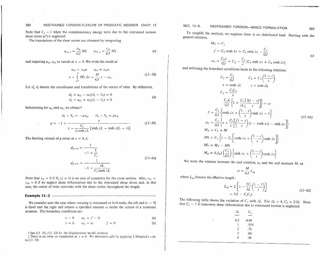
392 RESTRAINED TORSION-FLEXURE OF PRISMATIC MEMBER CHAP. 13 SEC. 13-6. RESTRAINED TORSION-MIXED FORMULATION 393 Note that C,= 1 when the complementary energy term due to the restrained torsion To simplify the analysis, we suppose there is no distributed load. Starting with theshear stress (ar) is neglected. general solution,
The translations of the shear center are obtained by integrating .MT = C1
Us2, x = G_ MT U3 = MU (c) f = C3 cosh Ax + C4 sinh ix -CGJ GJ GJ (c)
Clx Cand requiring U,2, U3 to vanish at x = 0. We write the result as =1 Co I + C2 - {C 3 sinh Ax + C4 cosh 2x}
U,2 - X3rU LIs3 = X2rI and enforcing the boundary conditions leads to the following relations:
(13-58)Ii =M dx= --- - ( I
f~M~.d GJ C3 = GJ(1)
C(-c)
Let x, tuj denote the coordinates and translations of the center of twist. By definition, c = cosh iL s = sinh AL
C,C4C2-
U' = U,2 - ¢) 1(3 - 3) = 0 I (d)
= U,3USt3 + Cdo1(x - 2) = 0 C87 1+ C 2(1 - c) o
Substituting for u,j and wcl, we obtain t CJ 1L){ )
f = G {cosh x + (--) sinh Ax -X' - 2 = --gx2, x3 - Y = gX3,. (13-61)
g= -1 + (13-59) (1- csh Ax) -- sinh axI}x ) { + F[iiS
x - ------ [sinh XL - sinh X(L - x)]Acosh XL Mr = C -M
The limiting valuesT of g occur at x = 0, L. M'r = C1 {1 - C cosh 2x + -- sinh 2x]}
M = MT - MTgVl=o- I
-1 + - M¢E,= rl (3) {sinh Ax + (lC ) cosh Ax}C,
(13-60) We write the relation between the end rotation, wc,and the end moment M, asgl, = - ,L
-1 + MC, tanh XL co=;'J ,,
where L,,, denotes the effective length:Note that xij = 0 if Xk (j k) is an axis of symmetry for the cross section. Also, x2, = x3 = 0 if we neglect shear deformation due to the restrained shear stress and, in this
case, the center of twist coincides with the shear center throughout the length. = L[1 - C - 1) (13-62)
I VC·N5I " 12 = L(1 - CC)r i~111111~ I~-l-l
We consider next the case where warping is restrained at both ends the left end x 0)
The following table shows the variation of C, with AL. For XL > 4, C _, 2,,L. NoteWe consider next the case where warping is restrained at both ends; the left end (x = 0) that C, = I if transverse shear deformation due to restrained torsion is neglected.is fixed and the right end rotates a specified amount co under the action of a torsional moment. The boundary conditions are XL CA
x=O 01 =.f=O (a) 0.5 0.98
x = L 0ol = f = 0 (b) 1 .924 2 .76
t See (13-31), (13-32) for the displacement model solution. 3 .60 . There is no twist or translation at x = 0. We determine g(0) by applying L'H6spital's rule 4 .48
to (13-59).

395 394 RESTRAINED TORSION-FLEXURE OF PRISMATIC MEMBER CHAP. 13
Example 13-3
Uniforin DistributedMoment-Symmetrical Supports
The general solution for mT = constant (we let nr = m for convenience) is:
MT = C1 - mx
C1 mxf =
C-3 cosh AX +
C- 4 sinh ;x - - + --L + L ; GJ (C sinh + C cosh
(a)W, =x C III x C C' (C, sinh,x + C, cosh A'x)
We consider the boundary conditions to be identical at both ends and measure x from the midpoint (Fig. E13--3). Symmetry requires
MT = } at x =-0 (b)
f = of
and (a) reduces to MT = --mx
C4 inf = C sinh Ax + -y x (13-63)
L GJJ
091 = C2 - - -+ oshx
We treat first the case where the end section is fixed with respect to both rotation and warping. Requiring (13-63) to satisfy
f = co = 0 at.x = L/2 (a)
results in
f = _. {x- 1 sinh x}
mL JI = mGJo
F sC ( x'\fljI+ 2sA (cosh Ax - c)}
MT = -mx
(13-64) = L+ sinh Ax}
M4, = -n 1 - L cosh ix}
AL AL c = cosh - s = sinh
2 2
The solution represents an upper bound. A lower bound is obtained by allowing the section to wrap, i.e., by taking
L co1 =f,x=0 atx=-- (b)
2
SEC. 13-7. APPLICATION TO THIN-WALLED OPEN CROSS SECTIONS
X2 Fig. E13-3
2 m 2 ;(t
L/2 - L2
and the result is
= j{x - Asinh Ax}
mL 2 I 4(x2 = :-{ 1 -4(L) j + c(,)2 (cosh ix - c)}
MT = -mx
(13-65)
2L c = cosh-
2
13-7. APPLICATION TO THIN-WALLED OPEN CROSS SECTIONS
In what follows, we apply the mixed formulation theory to a wide flange section and also to a channel section. We first determine the cross-sectional properties corresponding to 6 = - c/ and then obtain general expressions for the stresses in terms of dimensionless geometric parameters. Before discussing the individual sections, we briefly outline the procedure for an arbitrary section.
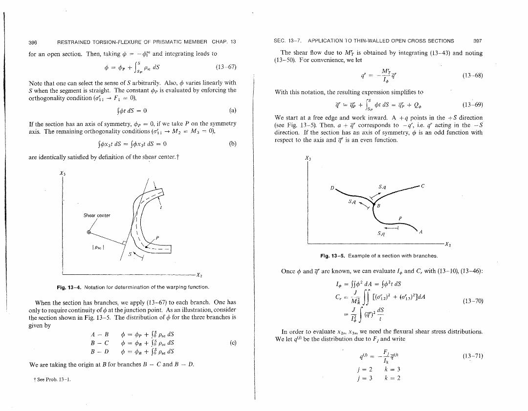
Consider the arbitrary segment shown in Fig. 13-4. We select a positive sense for S and an arbitrary origin (point P). The unrestrained torsion warping function is obtained by applying (11-29) to the centerline curve and requiring the section to rotate about the shear center.t
o-' CClscenterli - - -. ( $ + -'S t (13-66)t J C~S C)
where p,, is positive when translation in the + S direction rotates the position vector about the + X direction. The unrestrained torsional shear flow is zero
f By definition, k, = ArI/GJ. We work with q" rather than y'., to facilitate treatment of closed and mixed sections where one generates q" in terms of M./J.
396 397 RESTRAINED TORSION-FLEXURE OF PRISMATIC MEMBER CHAP. 13
for an open section. Then, taking = - s and integrating leads to
=P + sp p, dS (13-67)
Note that one can select the sense of S arbitrarily. Also, 0 varies linearly with S when the segment is straight. The constant OSp is evaluated by enforcing the orthogonality condition ( I - F1 = 0),
lot dS = 0 (a)
If the section has an axis of symmetry, p = 0, if we take P on the symmetry axis. The remaining orthogonality conditions (a - A 2 = M3 = 0),
S¢x 2t dS = f x 3 t dS = 0 (b)
are identically satisfied by definition of the shear center. t
X3
S
IPsc }
x2
Fig. 13-4. Notation for determination of the warping function.
When the section has branches, we apply (13--67) to each branch. One has only to require continuity of q at the junction point. As an illustration, consider the section shown in Fig. 13-5. The distribution of q5 for the three branches is
given by
A1--PR ¢ = + fS PS, dS
B + .fS ps, dS (c)B-C 0 = B
B-D q = DUB+ oSP,c dS
We are taking the origin at B for branches B - C and B - D.
t See Prob. 13-1.
SEC. 13-7. APPLICATION TO THIN-WALLED OPEN CROSS SECTIONS
The shear flow due to M'T is obtained by integrating (13-43) and noting (13-50). For convenience, we let
r M='= _ qr~ (13-68)
With this notation, the resulting expression simplifies to
r +p ¢t dS = + Q (13-69)
We start at a free edge and work inward. A +q points in the +S direction (see Fig. 13-5). Then, a + 4r corresponds to -qr, i.e. q" acting in the -S direction. If the section has an axis of symmetry, f is an odd function with respect to the axis and qr is an even function.
X3
D S,q
S,q A
y,*'
-2
Fig. 13-5. Example of a section with branches.
Once qf and qr are known, we can evaluate Is and C, with (13-10), (13-46):
2I, = JJc/ 2 dA = t dS
Cr = M2 JJ[('1 2 )2
+ ('&3)2 ]dA (13-70)
_ Jo ,(4r)2 dS
In order to evaluate x2 r, x 3r, we need the flexural shear stress distributions. We let q(J) be the distribution due to Fi and write
q(j) = F (j) (13-71)
j=2 k=3 i=3 k=2
398 RESTRAINED TORSION-FLEXURE OF PRISMATIC MEMBER CHAP. 13 SEC. 13-7. APPLICATION TO THIN-WALLED OPEN CROSS SECTIONS 399
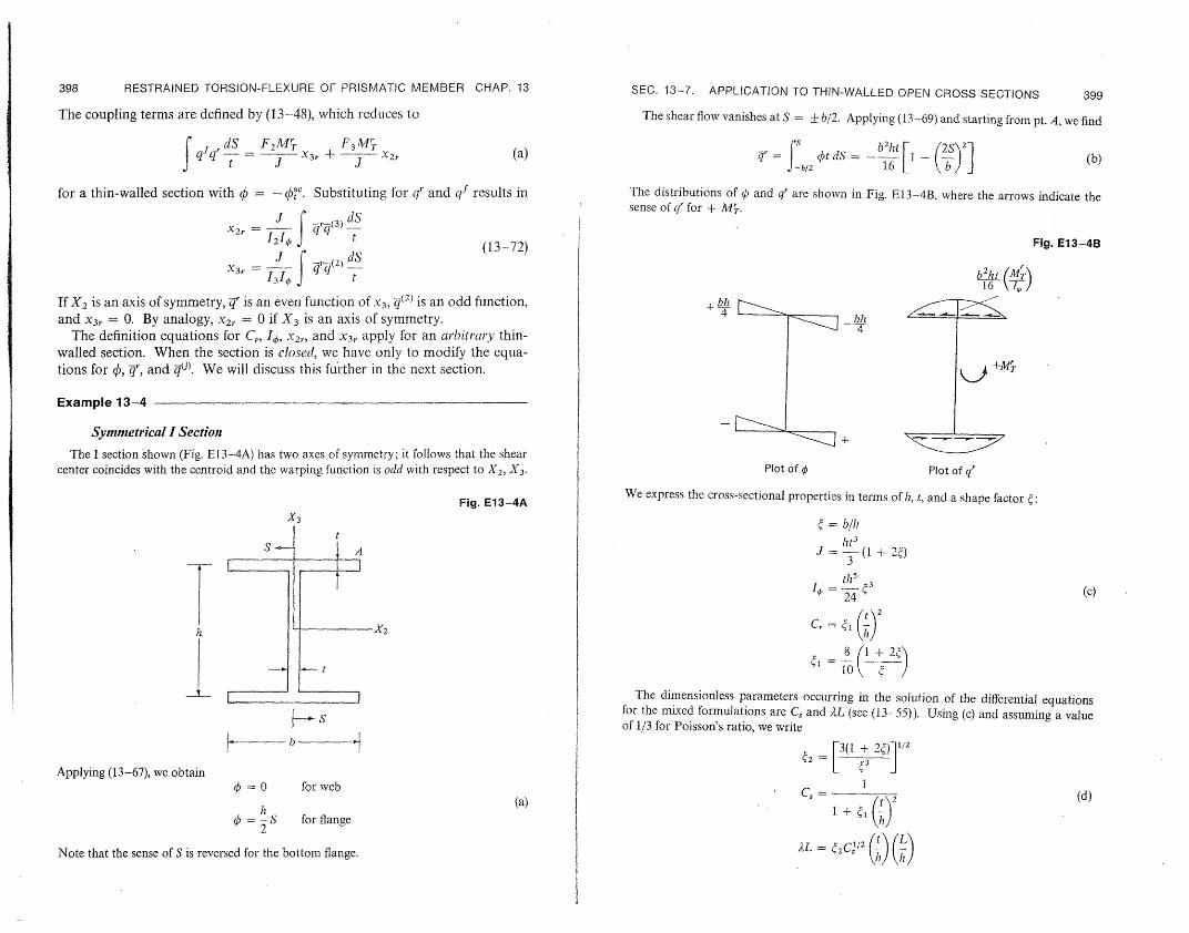
The coupling terms are defined by (13---48), which reduces to The shear flow vanishes at S = + b/2. Applying (13-69) and starting from pt. A, we find
i dS F2 MT F3 M't (a) =r S t dS b2ht I 2S 2 (b)t 3r +- 2 b/2 16 [ 3bJI
for a thin-walled section with q = - c. Substituting for q' and qf results in The distributions of 0 and q' are shown in Fig. E13-4B, where the arrows indicate the sense of qr for + M.
J Cf0 dSX2 r = I
12IXr I| Qq3t
t (13-72) Fig. E13-4B
J1 f ,1(2) dS X3r
134 J t b h16 (MT16 V7,-7
If X2 is an axis of symmetry, Z" is an even function of x3, z(2 ) is an odd function, +band X31. = 0. By analogy, X2,. = 0 if X3 is an axis of symmetry. 4
bh
The definition equations for C,., I, X2, and X3 r apply for an arbitrarythin-4
walled section. When the section is closed1, we have only to modify the equations for , , and 4(j). We will discuss this further in the next section. 4T
Example 13-4
Symmetrical I Section +
The I section shown (Fig. E13-4A) has two axes of symmetry; it follows that the shear center coincides with the centroid and the warping function is odd with respect to X2, X 3. Plot of ¢ Plot of qr
We express the cross-sectional properties in terms of h, t, and a shape factor :Fig. E13-4A
X3 = b/hl ht 3
J --- (( + 2)
thS 3
24 (c)
C, = r) 2
8 (i i2:+ 10 /
The dimensionless parameters occurring in the solution of the differential equations for the mixed formulations are C, and 2iL (see (13-55)). Using (c)and assuming a value
b-- of 1/3 for Poisson's ratio, we write l' 1,
r2=3(1 + 2)]1 2
Applying (13-67), we obtain = O for web I
(a) Cs = (d)
q = S for flange2
2 C (/2Note that the sense of S is reversed for the bottom flange. _L=IL /, (h)

__
400 401
RESTRAINED TORSION-FLEXURE OF PRISMATIC MEMBER CHAP. 13
The coefficients 4I, 2 are tabulated below:
b L = t1 42
hi
1 2.4 3 0.75 2.66 4.22 0.50 3.2 6.93
Since (t/h)2 << I and gl0(l), we see that C,, 1. The warping parameter, L, depends
on t/h as well as L/h. This is the essential difference between open and closed cross sections. For the solid section, we found that L = O(L/h) and, since L/h is generally large in comparison to unity, the influence of restrained warping is localizcd.t The value of AL for an open section is O(L/I) O(t/h) and the effect of warping restraint is no longclr confined to a region on the order of the depth at the end but extends further into the interior.
We consider next the determination of the stresses due to restrained warping. The general expressions are
M,
(e) ys = -t
t11 Using the distribution for k(tand q' shown above, the maximum values of normal and shear stress are
6
(f)ICI 3M3 il~slma
The shearing stress due to unrestrained torsion is obtained from
M'T 3 is = --- t = 2 + 2_ T (g)
.1 t2(1 + 2ht
To gain some insight as to the relative magnitude of the various stresses, we consider a member fully restrained at one end and subjected to a torsional moment M at the other end. This problem is solved in Example 13-1. The maximum values of the moments are
tanh .Li MT|ax = -MLC-
(h)
M"mx = CsM
We substitute for the moments in (f), (g) and write the results in terms of oa,, the maximum
t We defined the boundary layer length, Lb,, (see (13--24). (13-25)) as
- L" Lb 4 e . 0 -- ; -
L 2L
SEC. 13-7. APPLICATION TO THIN-WALLED OPEN CROSS SECTIONS
shear stress for unrestrained torsion:
amI. = (43C2 tanh IL)u,'CS/
I|71sl. = Xh (i)
a Mt
J 2
3 = iCaW2 o4 = (w3)
The variation of these coefficients with b/h is shown below:
b h 43 (4
1 2 1.5 0.75 2.11 1.67 0.50 2.31 2
Since Cs, f3. and 4 are of 0(1), it follows that
ci' 1m = 0(oU)
t (j) IkJ,= h-0(4:)
The additional shearing stress (,) is small in comparison to the unrestrained value. Therefore, it is reasonable to neglect the terms in the complementary energy density due to o',, i.e., to take C = 0 and C, - 1for an open section. We will show in the next section that this assumption is not valid for a closed section.
Example 13-5
CltannelSection
We consider next the channel section shown in Fig. E13-5A. Since X2 is an axis of symmetry, X = X3r = 0. The expressions for the location of the centroid, shear center,3
X3 Fig. E13-5A
S
Shear center t
am X2, h
S
51 - -__ __ ---- $_Lr,", ( e__ -A-

402 RESTRAINED TORSION-FLEXURE OF PRISMATIC MEMBER CHAP. 13 SEC. 13-7. APPLICATION TO TIN-WALLED OPEN CROSS SECTIONS 403
and 12 are
A = b . 1 + 25 -(1 - e)
Fig. E13-5B
th3 (a) k1)
I, = (1 + 6)12 l e <-
b
h
The dimensionless coefficient ' is essentially constant, as the following table shows: +(l- e)
5 b
h Distribution of ¢/__
1.00 0.429 Fin_ E1.-'C
0.75 0.50
0.409 0.375 0
We determine 4bby applying (13-67) to the three segments. aking S as indicated above, and noting that 10is odd with respect to X 2, we obtain:
I
Segment 1-2 t 1 2
Psc = h 2 t I -) L
= bh ( �F -) (b)
Segment 2-3
Psc= +e (D0,3(-) =- 2-1 +) -)e
The distribution is plotted in Fig. E13-5B. Since 7 < 1/2, the maximum value of 0 occurs at point 1 (and 4). Distribution of q/bh2t
We generate next the distribution of Z', starting at point I (since q = and using (b):
0 at that point) The expressions
example: tor J, I0, C, C, and AL are written in the same form as for the previous
Segment 1-2 J = ht3 (+ 2)= ht3) j
,r= f
opt dS = (I-)S-IL 2bI
(c)(C)
Segment 2-3 A = 5I + 3{(l + 2)(3 (+ L) + 422 2 3()j t 2(' ) I (d)
= (r + bhte (_ S+2) C t + C
The distribution of q' is plotted in Fig. E13--5C.

SEC. 13-8. THIN-WALLED CLOSED CROSS SECTIONS 405 404 RESTRAINED TORSION-FLEXURE OF PRISMATIC MEMBER CHAP. 13
The following table shows the variation of il and .2with b/h for G/E, = 3/8. i.e., Poisson's Substituting for 4', 4(3), and the cross-sectional constants in (13-72) leads to
ratio equal to 1/3. Note that the comments made for the wide-flange section also apply X2,. = -b63 (t)to the channel section.
b (1 + 2)(-0.2 + 5 2 + 6 3)
3= + 2(1 60)(2 + 3) (f)h
El 842
The coefficient is of order unity, as the following table shows: 1 2.33 2.55 0.75 2.65 3.39 3 0.50 3.4 5.24
1 0.926
In order to evaluate x2r, we need the flexural shear stress distribution due to F3. Applying 0.5 1.03
(11-106) leads to In Example 13-1, we determined expressions for the coordinates of the center of twist in terms of xjr and C,. It is of interest to evaluate these expressions for this cross section.
Segment 1-2 The coordinates at x = 0 (see (13-59), (13-60)) are
ht S X = 0
Z(3) = S x2 = 2 - X2,lglx= o (g)2
Segment 2-3 (e) - 1
Cs q(3) = - bht St (h - S) Substituting for C8, X2,, and evaluating x2,2 2
The distribution is plotted in Fig. E13-SD; the arrows indicate the sense of q for a +F.3x = -(a + e)= -b +-+ - = 4,4b (h)
we obtain Fig. E13-5D
X[2 = 2( - ,5) (i) ,3 (j)
0 Typical values are listed below:
-(I + X 4 5t
1 0.476 0.836 0.5 0.625 0.485I t1
13-8. APPLICATION TO THIN-WALLED CLOSED CROSS SECTIONSI I I We treat first a single closed cell and then generalize the procedure for multi
cell sections. Consider the section shown in Fig. 13-6. The +S direction is0 from X2 toward X3 (corresponding to a rotation about the +X 1 direction).
-I Using the results developed in Sec. 11-4, the shear flow for unrestrained torsion is
MT 2A Distribution of lb2ht q = C C
(a) t
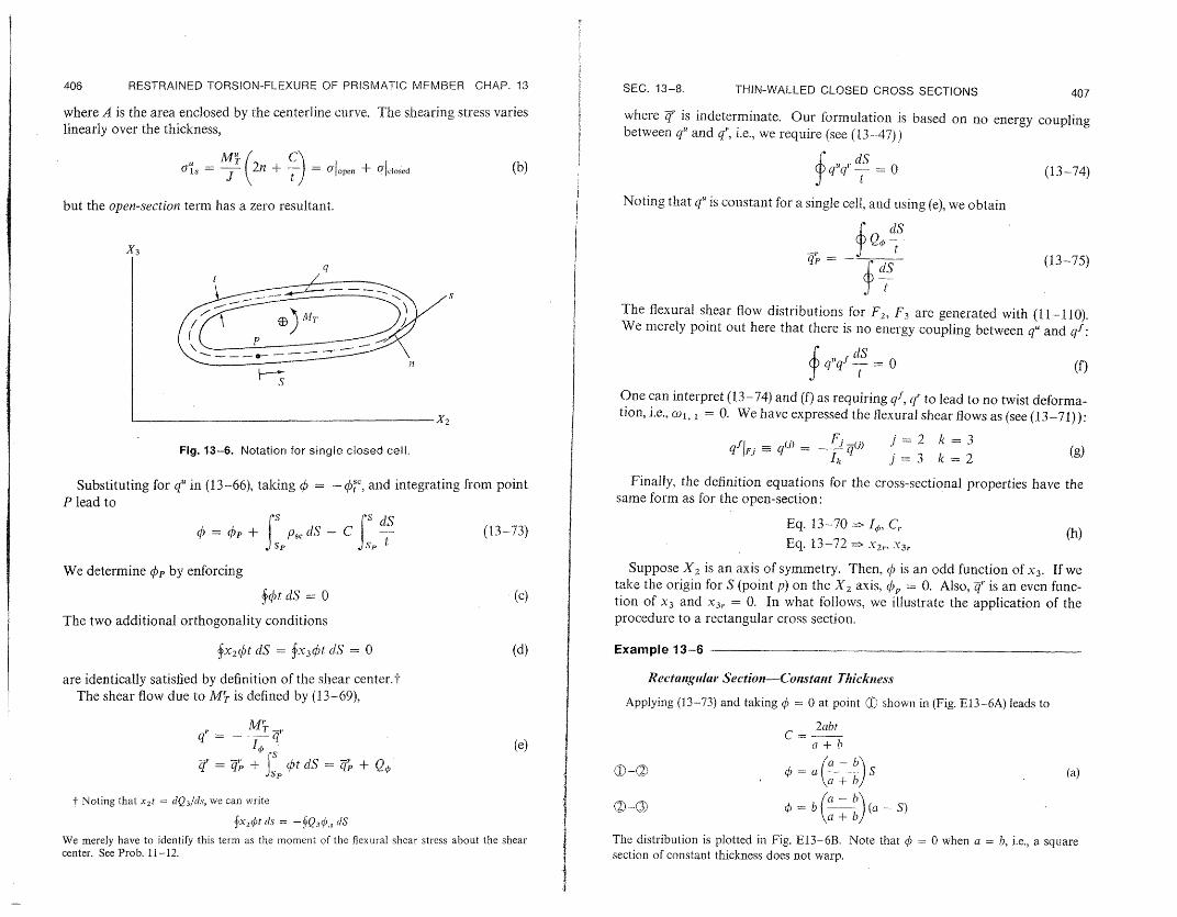
406 RESTRAINED TORSION-FLEXURE OF PRISMATIC MEMBER CHAP. 13 SEC. 13-8. THIN-WALLED CLOSED CROSS SETIONS 407
where A is the area enclosed by the centerline curve. The shearing stress varies where c/ is indeterminate. Our formulation is based on no energy couplinglinearly over the thickness, between q" and qr, i.e., we require (see (13--47))
a., = -- 2n + = Jljopen + 'closed (b) Nqsl dS e (13-74)
Noting that q is constant for a single cell, and using (e), we obtainbut the open-section term has a zero resultant.
X3 dS (13-75)q
t
The flexural shear flow distributions for F2, F3 are generated with (11-110). We merely point out here that there is no energy coupling between q and qf:
q d(IS(f)
s One can interpret (13-74) and (f) as requiring qf, q' to lead to no twist deforma-
X2 tion, i.e., co , = 0. We have expressed the flexural shear flows as (see (13-71)):1
k=3 Fig. 13-6. Notation for single closed cell. qfl qj) = -_ q(j)I j=2
(g)k, j= 3 k=2
Substituting for qU in (13-66), taking = - , and integrating from point Finally, the definition equations for the cross-sectional properties have the P lead to same form as for the open-section:
4 = 1p + PsS - C (13-73) Eq. 13-70 I4,, C,. (h)
Eq. 13-72 => -Y2, 3r
We determine Op by enforcing Suppose X2 is an axis of symmetry. Then, ( is an odd function of 3. If we take the origin for S (point p) on the X2 axis, <;p = 0. Also, q' is an even func-
fr()t dS = 0 (c) tion of X3 and X3,. = 0. In what follows, we illustrate the application of the The two additional orthogonality conditions procedure to a rectangular cross section.
fx 2 #)tdS = .x43 )t /dS = 0 (d) Example 13-6
are identically satisfied by definition of the shear center.'t Rectangular Section-Constant Thickness The shear flow due to M5 is defined by (13-69), Applying (13-73) and taking = 0 at point shown in (Fig. E13-6A) leads to
M _,. 2abt C b
(e) + b/Ic=a a=
I0£ Sd<t dS = + Q0 =
[cta--
- bJt S (a)T= l-~ + SP
t Noting that x2t = dQ 3/ds, we can write ¢ = b a - b (-S)
X2 1t ds - (Q3 4,. IS
We merely have to identify this term as the moment of the flexural shear stress about the shear The distribution is plotted in Fig. E13-6B. Note that = 0 when a = b, i.e., a square center. See Prob. 11-12. section of constant thickness does not warp.

--
4108 RESTRAINED TORSION\-FLEXURE OF PRISMATC MEMBER CHAP. 13 SEC. 13-8. THIN-WALLED CLOSED CROSS SECTIONS 409
X3 Fig. E13-6A The distribution ofqr follows from (b), (c),
1-(X
/ If3
S5
0 ©-
{(5)2-=D( (1 2a 1
(d)
D = a b 2t a ba
2 b Centroid
/ IS X2
2b b a 3
and is plotted in Fig. E13-6C. Note that +qr corresponds to q"(-S) direction for +M'. Also, D is negative for b > a.
acting in the clockwise
- t
J Fig. E13-6C
I 2a--- .2a- X3
-a- S H Fig. E13-6B
X2
vael vurlvs vi yr i
We determine Qp by integrating (a),
(a - ba S2 Qqat I- I_ for segment 1-2
qr/D
(b)
Q = (Q)2 bt ( ) (aSb for segment 2-3 qr(+ ) =Al -IO 2 a +b
and evaluate qpr with (13-75):
(t, dSdS We introduce a shape factor ,¥,p = -I
= b) 6) (2a b) (c)
depth b t width a (e) - a +b (It

410 RESTRAINED TORSION-FLEXURE OF PRISMATIC MEMBER CHAP. 13 SEC. 13-8. T~IN-ALLED CLOSED CROSS SECTIONS 411
and express the various coefficients in terms of a, t, and a. The resulting relations are The maximum normal stress occurs at point 2 while the maximum shear stress can occur at either points I or 3.
We consider the same problem as was treated in Example 13-4. i.e., a member fullyJ = 16a3I (neglecting the contribution of Jo) restrained at one end and subjected to a torsional moment M at the other end. We ex
press the stresses in terms of a', the maximum shear stress for unrestrained torsion,
I 3 L 1+ 6, = - (t + -) (j)
4 1 + 5 + 5&2 + 3 ' = t+ which reduces to5 1 _ _ 2 + 3
MC M5(1 _-)2) (k)
J 2At (f) since we are considering the section to be thin-walled. The maximum stresses are
XL = I' - = O'i; I maxatFPoit = 1 tanh ;XL2
{C () 0 I 2C, - -I (Xr12X2 )t/2L L (I) X2.i = X3r = 0
,"'= 1/2 The variation of C,, C, and &-with b/a is shown in the table below:
F(EatJr> /t--S b
,=- C, C, for-- = a The variation of 41 and 2 with height/width is shown below. We are taking Poisson's
ratio equal to 1/3.1 oc 0 0.98 2 10.43 0.0877 1.27 - = b/a ,i (point 2) C2 (point 1) (2 (point 3)3 4.41 0.185 1.39
1 0 0 0 We found 2 -1.04 -0.35 + 0.44
C, = ( 3 -1.51 -0.46 + 0.65 IIJ
For large L, tanh XiL 1 and we see that both the normal and shear stress are of the C, +0 ()2 (g) order of the unrestrained-torsion stress. In the open section case, we found the restrained
torsion shear stress to be of the order of (thickncess/depth) times the unrestrained shear t )0 (,L h )2 stress.
for an open section. Our results for the single cell indicate that To illustrate the procedure for a multicell section, we consider the section shown in Fig. 13-7. The unrestrained-torsion analysis for this section is treated
J.L = - in Sec. 11-4 (see Fig. 11-11). For convenience, we summarize the essential restilts here.
C,. >>1 (h) We number the cells consecutively and take the +S sense from X2 to X3I.Cs <<c for the closed segments and inward for the open segments. The total shear
for a closed section. We obtained a similar result for AL, using the displacement-model flow is obtained by superimposing the individual cell flows q, q'.
formulation for a solid section. Since C, is due to the restrained shearing stress (qr), we q" = 0 for an exterior (open) segment see that shear deformation due to q cannot be neglected for a closed cross section. oal
We discuss next the determination of the normal and shearing stresses due to warping. 11 = constant for an interior segment
The general expressions are We let
IM, = q M, (i)n t() Gt qi= -cj (b)
3

412 413 Il
RESTRAINED TORSION-FLEXURE OF PRISMATIC MEMBER CHAP. 13
e
q,S
ql ,S1
Fig. 13-7. Notation for mixed cross section.
The constants C1, C2 are determined by requiring each cell to have the same
twist deformation, co1, 1. Enforcing (11-67), t
? (c)1s dS = 2co1, Aj = 2 G. Aj
for each cell leads to aC = 2A (d)
where a, A are defined as
dS sJ t
a dS (12 = a21 = - - (e)
cA t
A = {i, A2
The warping function is generated by applying (13-6):
(13-76)
) = as 4)-Psc-t1t tt
We start at point P1 in cell 1 and integrate around the centerline, enforcing continuity of q at the junction points b, c, and d. For example, at b, we require
)bIPb = blebh (f)
SEC. 13-8. THIN-WALLED CLOSED CROSS SECTIONS
which leads to a relation between 4)e and /),:
psc dS = p + f ps CC' dS+ bOb = e + (g)
Repeating for points C and d results in the distribution of 0 expressed in terms of P,,. One can easily verify that q is continuous, i.e., Ap determined from segment ca is equal to qj, determined from segment cda. Finally, we evaluate 0,, by enforcing t
fft dA = fqt dS = (h)
where the integral extends over the total centerline. Note that p,= 0 if P1
is taken on an axis of symmetry. The shear flow for restrained torsion is obtained with (13-69):
as r = o)t (i)as
The steps are the same as for the flexural shear determination discussed in Sec. 11-7. We take the shear flow at points P,, P2 as the redundants,
lff = C j =1, 2 (13-77)
and express the shear flow as T = Io + 4c (13-78)
where Tz0 is the open section distribution and Z7, is due to C';, C. The distribution, 4q, has the same form as q"/(M7./J). We just have to replace C with C'r. We generate q0 by integrating (i) around the centerline, and enforcing equilibrium at the junction points. For example, at point b (see Fig. 13-7),
qb = qbP, + ibe (j)
Note that 7 = 0 at points P, P2, e andf The redundant shear flows are evaluated by requiring no energy coupling
between qU and q which is equivalent to requiring q' to lead to no twist deformation, cow, 1. Noting (c), we can write
sj r
d S
t 0 j= 1,2 (13-79)
Finally, substituting for t',we obtain
aC = B (13-80)
B = - 40 t
? See also (11-32). t See footnote on page 385.

414 RESTRAINED TORSION-FLEXURE OF PRISMATIC MEMBER CHAP. 13
Once and 4" are known, the cross-sectional properties (I , Cr, X2r, X3r)
can be evaluated. Also we can readily generalize the above approach for an
n-cell section.
13-9. GOVERNING EQUATIONS-GEOMETRICALLY NONLINEAR RESTRAINED TORSION
In this section, we establish the governing equations for geometrically non
linear restrained torsion by applying Reissner's principle. This approach is a for both stresses and dismixed formulation, i.e., one introduces expansions
placements. The linear case was treated in Sec. 13-5. To extend the formulation
into the geometrically nonlinear realm is straightforward. One has only to
introduce the appropriate nonlinear strain-displacement relations.
Our starting point is the stationary requircment t
b[ffj(aT - Tru - V*)d(vol.) - fpT't d(surface area)] = 0 (a)
where , u, are independent variables, E - e(u), V* = V*(Y), and p, b are
prescribed. We take the displacement expansions according to (13-3) and use the strain
displacement relations for small strain and small finite rotations:}
i 1 = ul1 + (o2X3 - 03x2 + .)
C==1 Us2 - (01(X3 - -13)
1/3 = Us3 + O)(X 2 - -X2) (13-81) =l'. +_(a2+ .t1)=
-Y12 = 1,2 + 12, 1 + 13,1113,2
-Y13 = 1, 3 + 1U3,1 + 2, 112, 3
The in-plane strain measures (82, 3 , '23) are of O(,2), which is negligible
according to the assumption of small finite rotations. Actually we assume
33 = u2 3 = 0, i.e., plane stress. Substituting for the displacements and(22 -= noting the definition equations for the force parameters, the first term in (a)
expands to
1 20 1 ,)2]JffJTE d(vol.) = .xl {Fl [u1, ± t(z1, I ± 3s 1. 1)2 +- US3 1
,3 - 2o1, )]+ F2 [U,2 . - 03 + t( Us
+ F3[U,,3 + ()z - )I0(U2, 1 + 30 1 ,1 )]
± M2[1o2, - o, 1(us2, 1 + X3. .1 1)] (13-82)
± M3 [o 3, 1 - l., l(u.,3, 1 - i2 t1 1)]
+ MTIO, 1 + Muff 1 + MR.f
+ TMpWo , 1 + MQ 1cl1),1 (t}X1
t See Eqs. 13-33 and corresponding footnote. We are working with Kirchhoff stress and
Lagrangian strain here. - See Sec. 10-3, Eq. 10-28. The displacement expansions assume small-finite rotation, i.e.,
sin co ~ co and cos co ; 1. To be consistent, we must use (10--28).
SEC. 13-9. GOVERNING EQUATIONS 415
where the two additional force parameters are
Mp = ifcil1(X + X32A
+ 3o 13 )dAMQ = ( 2O'1 2
The terms involving the external forces have the same forin as for the linear
case, but we list them again here for convenience (see (13-6)):
JftbTu d(vol.) + JPTu d(surface area)
$x,(blu + b2us2 + b3ul 3 + MTWOl + 1720 2 + m3 )w + nlof)dxl (13-83) 1 3
f13(03 + Mf'lx,=O,L+ IF1ul F2Us2 + F3 uis3 + MTC1 + - 2(02 +
where the end forces (the barred quantities) are defined as previously, for example,
FII-, = = ( p1 dA~x, = etc.
It remains to introduce expansions for the stresses in terms of the independent
force parameters and to expand V*. In the linear case, there are 8 force
measures, F1,.. . M3, and M,, MR. Two additional force measures (MP, MQ)
are present for the nonlinear case but they can be related to the previous force
We proceed as follows. We use the stress expansions employed formeasures. the linear case with ) = -q)". They are summarized below for convenience
(see Sec. 13--5):
A '2 13
9lj = cr{j + 'j + crqi
'I j = T
7'MR (a) OIj J=
fij = ij2F 2 + h3F3
MT =MT + M.
MR MT
where 4,f, g, h2 and h3 are functions of x2, x. Introducing (a) in the definition
equations for Me and M e leads to
Mp = / 1F1 + f 2M2 + fl 3M3 + P/31Vf
A- (x~ ± .v~)A AIK
31 r /32 IjX32 3)dA (13-84)
2+ /3 x2(X2 + x )dA/5 = iJj
416 RESTRAINED TORSION-FLEXURE OF PRISMATIC MEMBER CHAP. 13 SEC. 13-9. GOVERNING EQUATIONS
417andt where
MQ = 2F2 + 1 3F3 + XT'T- I+ TIM
(hk 31 = 1 + 2 + (hcrc== S(hk + x3h3 k)dA (k = 2, 3) (13-85)/2 = - 3 3 = 13+22 32 = 2 -x3 ]33 = ½3 + X21() = (.f(x2J2 + .C3f)dA
Certain coefficients vanish if the cross section has an axis of symmetry. + One Force-DisplacementRelations can readily verify that
F1 (13-86) AE 1 2 + 2U3, 1 + c1, 1 (T3u 2. 1, X2us3, + 1#loI, 1)MQ => O
when the section is doubly symmetric. For generality, we will retain all the G + A1 3T21;2+ XJ! ~MT l US2 1 - 3 (I13Us 1 - 01, 133]terms here. 3
The complementary energy density function has the same form as for the linear case: GIlji- + -_J'MT 113 1 (2 + (01-Us2, 1 + (01, 132]
1 FM2 M /'M+ M'fV * _12E +-2 I3 + -- I2Ek\A 12 13, 2E GJ = cO1. (1 + 'o 1 )
)21 (2 F + -((M') 2 + C(MF3) (13 87) M2 (13-88) + 2G 2 A 23 A 3 2GJ
11E -- ,(-s2. (01. (-U, 2 1 ++ /3()1, 1)
+ MGJ (X3rF2 + X2rF 3) EM3
We have shown that it is quite reasonable to neglect transverse shear deformation due to warping (Cr = x2 r = X3 = 0) for a thin-walled open section. E - f. + &1,c. 1
Substituting Equations (13-82)-(13-87) in Reissner's functional and re-quiring it to be stationary with respect to the seven displacement and eight GJ [CrMiT X3 ,F2 XrF 3 ]=
force measures leads to the following governing equations: + (0. 1(1 + 1(0 1)
Equilibrium Equations Boundary Conditions (+ for x = L, -for x= 0) Flt, + b = 0 u1 prescribed or F1 -Ft
dx d
{F1(1,2, 1 + x 3c 1, 1 + F2 - 1F3 - o1, M2} + b2 = u~2 prescribed or Fi(us2 1 -3ol, 1) + F2 -C wF 3 - o1 1M2 = +F2 u,3 prescribed or F1(us3 - 2 ol, 1) +-F3 + (iF ;F3
dx d
{F1 (U, 3, 1 - 2o)1 , 1) + F3 + 0coF 2 - t, 1M3 } + b3 = 0 0ol prescribed or F( 3Us, 2 1 - 2(3, 1 + fi1.1, t)
2 - (01, 1 M 3
(1 rirc)A'iM, + ((1 ++ +)M)M r, + + O1(72F2 + 3F3) + (I + 'i1wlo)Mr + (1 + Io T)M.
1 + M 2(-Us2 1 - 22c(01 ) + M3(-tlt3,1 + 2/3(01L ) +-c(1 , lM = ±M - F2Us 3, 1 + F3Us 2, 1 + ( 1 (-/ 3 F2 1 + 2 F3 . 1) (02 prescribed or M2 = ±M 2
+± {FI(X3Us2 1 - 2tls3, 1 + 101,1) + M 2 (-Us2, 1 + 22(01,1) c03 prescribed or M 3 = ±+M3
f prescribed or M =±+M + M 3(- u3, 1 + 23c)1, 1) + M1Wi/o,l} = 0
M2,1 - F3 + m2 = 0 These equations simplify considerably when the cross section is symmetrical
M 3, 1 + F2 + m3 = 0 and transverse shear deformation is neglected.t We discuss the general solution of (13-88) in Chapter 18. The following example treats one of the simplestM,t -M'r +±Im = O cases, a member subjected to an axial force and torsional moment.
t See Prob. 13-11. f See Prob. 13-12. t See Prob. 13-13.

____ - -
418 RESTRAINED TORSION-FLEXURE OF PRISMATIC MEMBER CHAP. 13 SEC. 13-9. GOVERNING EQUATIONS 419
where Example 13-7
We consider a prismatic member (see Fig. E13-7A) having a doubly symmetric cross p = P/h
-_ GJ
P1,Pll GJA
section, fully restrained at one end and loaded by an axial force P and torsional moment M. We are interested here in evaluating the influence of axial force on the torsional behavior. The linear solution (with no axial force) was derived in Example 13-1.
i 2 J 1- P ErI o I + C,(1 + P)
This expression reduces to Equation (g) of Sec. 13-6 when P = 0. Once f is known,
X2 Fig. E13-7A we can determine the rotation by integrating (d), which expands to
,l, [GJ (I + P = M - J- (f)
X1 P M when we substitute for M, using (b). P M The general solution is
F _ L_-f = C cosh tx + C2 sinh ftix
M J
GJ( + P) (g)
Equilibrium Equations (symmetrical cross section and no distributed load) OJ [GJ( + P - )
Mr = M,I., C=c3 + M 1+ -jCl s C {C, sinh ,x + C2 cosh l1X}
FI .t = 0 (a)
d j/7; (M + Flflo. ) = 0
(We drop the subscript on xi for convenience.) boundary conditions result in
Finally, specializing (g) for these particular
M Force-Displacement Relations f GJ(1 + -){- 1 + cosh ytx - tanh pL sinh [ix}
M' = GJol,. t
G;J M'i= -(f + WI ,)
Cr
dM= E,.If I (b) These equations reduce to (13-57) when P 0.
A tensile force (P > 0) increases the torsional stiffness whereas a compressive force F = AEul.l + EI w)j (P < 0) decreases the stiffness. Equation (h) shows that the limiting value of P is - 1. We
let P,. represent the critical axial force and c,.the corresponding axial stress
Boundary Conditions GIJA
xI = L F X1 =0 = P
i= -10MO = 0
= f =O M1 + f31Fiwl, = M
(c)
Per -0 11
(i)
IIGJ 1rc
Integrating the last two equations in (a) and noting the boundary conditions, lead to In order for gcr to be less than the yield stress, (J/l1 ) must be small with respect to unity. As an illustration, consider the section shown in Fig. E13-7B. The various coefficients
F = const = P - (see Example 13-4) are
M + ,1Ftl, I =
The first equilibrium equation takes the form
const =-- M tot) ,
I,
= bh
= I2 - 13 = th' 1
2 + 3 + 3)
ht 3
f 1-1-/.t2f = AGJ( + P)
(e) J = 3-(13 + 2) (j)

--
- - ---
420 RESTRAINED TORSION-FLEXURE OF PRISMATIC MEMBER
X3
I
X2
t tI
i I -I I
I -
I - -- b - .... i
and af (t 2 ( 2 + 4 )
-- G - A + 3d + T3)
REFERENCES
I. VON KARMAN, T., and N. B. CHRISTENSEN: "Methods of Analysis of Torsion with Variable Twist," J. Aero. Sci., pp. 110-124, April 1944.
2. TIMOSHENKO, S. J.: "Theory of Bending, Torsion and uckling of Thin-Walled Members of Open Cross Section," J. Frankliz Inst., pp. 559-609, 1945.
3. VON KARMAN, T., and W. C. CHIEN: "Torsion with Variable Twist," J. Aero. Sci., Vol. 13, No. 10, pp. 503-510, October 1946.
4. BENSCOTER, S. U.: "Secondary Stresses in Thin-Walled Beams with Closed Cross Sections," NACA-TN 2529, Washington, D. C., 1951.
5. BENSCOTER, S. U.: "A Theory of Torsion Bending for Multicell Beams," J. Appl. Mech., Vol 21, No. 1, 1954.
6. VLASOV, V. Z.: Thin Walled Elastic Beams, Israel Program for Scientific Translations, Office of Technical Services, U.S. Dept. of Commerce, Washington, D.C. 1961.
7. HEILIG, R.: "Der Schuberverformuneseinfluss auf die Wl6bkrafttorsion von Stiiben mit offenem Profil," Der Stahlbau,April 1961.
8. HEILIG, R.: "Beitrag zur Theorie der Kastentr:iger beliebiger Querschnittsform,'" Der Stahlbau, December 1961.
9. ODEN, J. T.: Mechanics of Elastic Structures, McGraw-Hill, New York, 1967. 10. KOLLBRUNNER, C. F., and K. BASLER: Torsion in Structures,Springer-Verlag. Berlin,
1969. II. WASHIZU, K.: Variational Methods i Elasticity and Plasticity, Pergamon Press,,
1968. 12. MAISEL, B. I.: "Review of Literature Related to the Analysis and Design of Thin-
Walled Beams," Technical Report 440, Cement and Concrete Association, London, July 1970.
CHAP. 13
Fig. E13-7B
PROBLEMS 421
13. DABROWSKI, R.: "Gekriimmte dinnwandige Triger," Springer-Verlag, Berlin, 1968. 14. GALAMBOS, T. V.: StructuralMembers and Franmes, Prentice-Hall, 1968. 15. BLECH, F.: Buckling Strength of Metal Structures, McGraw-Hill, New York, 1952. 16. BURGERMEISTER, G., and H. ST.UP: Stabilitat Theorie, Part I. Akademie Verlag,
Berlin, 1957. 17. CHILVER, A. H.: Thin-Walled Structures, Chatto and Windus, London, 1967. 18. REISSER, E.: "Note on Torsion with Variable Twist," .1. Appl. Mech., Vol. 23, No. 2,
pp. 315-316, June 1956.
PROBLEMS
13-1. The shear stress distribution due to F2 is given by (see (11 -95))
F2 - F2 3 012 =
I3 - 02r, 2 0'13 ' -- 2r, 3
13
where P2r,are flexural warping functions which satisfy
2V ;2r = - X2 (in A)
-0o (on S)On
al
This result applies when the cross section is assumed to be rigid with respect to in-plane deformation. The coordinate of the shear center is defined by
x31,c = - -- 3 - 32r, 2)dA (a)I J(X22' Show that (a) reduces to
-Ijy<3 |x 2 (t,dA
where )l,is the St. Venant torsional warping function. Hint: See Prob. 11-11 and Equation (11-97).
13-2. Verify (13-40) and (13-44). 13-3. This problem reviews the subject of the chapter in two aspects.(a) No coupling between the unrestrained and restrained torsional dis
tribution requires
((12S'12 + '"i3rl3)dA = 0 (a) The unrestrained torsional shear stress distribution for twist about the shear center (see Sec. 13-3, Equation (b)) is given by
12 = --- [ 't, 2 - X3 + .-3]
!MUU (b)Or13 - [0',C3 X2 - ]
The restrained torsional shear stress distribution is determined from (13-39). Verify that M = MR when 0 = t" and (a) is enforced.

--
II
i
i
CHAP. 13 422 RESTRAINED TORSION-FLEXURE OF PRISMATIC MEMBER
(b) When the cross section is thin-walled, (a) and (b) take the form
iq" dS= 0 (c) fs -- t
a s t - iCIJ c ( 5 / 1 (d)
where [IPol is the perpendicular distance from the shear center to the from (11-29) and
tangent at the centerline. Equation (d) follows Finally, the force param-
Prob. 11 -4. We determine qr from (13-43). eters for the thin-walled case are defined as
Ml = q'p,cdS (e) sqr.MR = s dS
Verify that Mr =- MR when (¢, - 42. Consider the following cases:
1. Open section 2. Closed section 3. Mixed section
13-4. Specialize (13-57) for XL >>1 and compare Mr vs. M". Also evaluate
co at x = L and compare with the unrestrained value. 1 13-5. Refer to Examples 12-2 and 13-2. Discuss how you would modify
the member force-displacement relations developed in Example 12-2 to account X1, X2r -=3r 0, and--
for restrained torsion. Consider Cs (a) warping restrained at both ends
(b) warping restrained only at x = L
13-6. Refer to Example 13-2. Determine the translations of the shear
= 0. Discuss how the solution center. Consider the cross section fixed at x
at x =L is restrained againstcross sectionhas to be modified when the translation. on the mixed
13-7. Starting with the force-deformation relations based
formulation (13--49), derive the member force-displacement relations (see = + 1.
Example 12-2). Consider no warping at the end sections and take Co
Specialize for-(a) symmetrical cross section (b) no shear deformation due to restrained torsion and flexure-arbitrary
cross section. 13-8. Consider a thin-walled section comprising discrete elements of
dlifferent material properties (E, G). Discuss how the displacement and mixed
formulations haveto be modified to account for variable material properties.
The unrestrained torsion and flexural stress distributions are treated in Note: Prob. 11-14 and 12-1. Cr, X2r.,
13-9. Determine the distribution of O, qr, and expressions for I,
x3r for the cross sections shown in parts a and b and part c-d of the accom
panying sketch (four different sets of data).
13-10. Determine 0 and qr for the section shown.
Using the flexural shear distributions listed in Prob. 13-1, show13-11.
that 12 -2P3
_t T
_L
-1, 2h -- I
(a)
t-- h Pi..c----- 2h
(c)
t
0 t Qjs,
t
|<-- a
PROBLEMS 423
Prob. 13-9
Ar t
[5-_
-_11
O--0.75h i
(b)
T h
_I See part c,
(d)
- + - - ---c
Prob. 13-10
t
0L s 2 a
t
2a ---
424 RESTRAINED TORSION-FLEXURE OF PRISMATIC MEMBER CHAP. 13
Hint: One can write
. (X2 V2( 2 r + X2 V2)dA
Also show that I33tj3 =:: 122
13-12. Specialize Equations (13-84) and (13-85) for the case where the cross section is symmetrical with respect to the X2 axis. Utilize
SJfe(X2 , X3)Ho(x2, x 3)dA = 0
where He is an even function and H,, an odd function of x 3. Evaluate the coefficients for the channel section of Example 13-5. Finally, specialize the equations for a doubly symmetric section.
13-13. Specialize (13-88) for a doubly symmetrical cross section. Then specialize further for negligible transverse shear deformation due to flexure and warping. The symmetry reductions are
X2 = X3 = 0 X2r = X3r 0y
h2 = = I/A 2 3 = 0[3 172 = 1/3 - 1' = i7 -- 0
13-14. Consider the two following problems involving doubly symmetric cross section.
(a) Establish "linearized" incremental equations by operating on (13-88) and retaining only linear terms in the displacement increments. Specialize for a doubly symmetric cross section (see Prob. 13--12).
(b) Consider the case where the cross section is doubly symmetric and the initial state is pure compression (F, = -P). Determine the critical load with respect to torsional buckling for the following boundary conditions:
1. co1 =f=0 at x = 0, L (restrained warping) df
2. oe = =0 at x = 0, L (unrestrained warping)dx
Neutral equilibrium (buckling) is defined as the existence of a nontrivial solution of the linearized incremental equations for the same external load. One sets
F1 = -P
-t2 = U3 = Cl = CO2 = (03 = f -- 0
and determines the value of P for which a nontrivial solution which satisfies the boundary conditions is possible. Employ the notation introduced in Example 13-7.
13-15. Determine the form of V, the strain energy density function (strain energy per unit length along the centroidal axis), expressed in terms of displacements. Assume no initial strain but allow for geometric nonlinearity. Note that V = V* when there is no initial strain.
14
Planar Deformation of aPlanar Member
14-1. INTRODUCTION: GEOMETRICAL RELATIONS
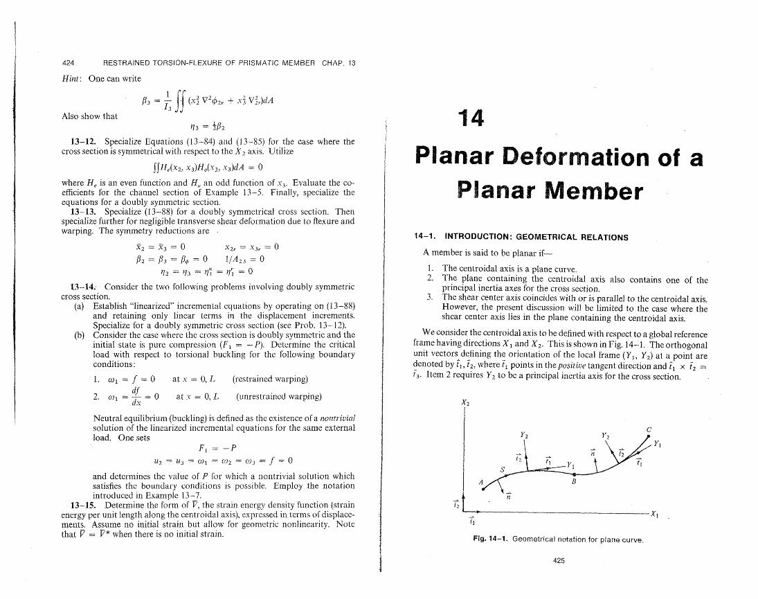
A member is said to be planar if
1. The centroidal axis is a plane curve. 2. The plane containing the centroidal axis also contains one of the
principal inertia axes for the cross section. 3. The shear center axis coincides with or is parallel to the centroidal axis.
However, the present discussion will be limited to the case where the shear center, axis lies in the plane containing the centroidal axis.
We consider the centroidal axis to be defined with respect to a global reference frame having directions X1 and X2. This is shown in Fig. 14-1. The orthogonal unit vectors defining the orientation of the local frame (YI, Y2) at a point are denoted by t, t2, where t, points in the positive tangent direction and ft x t2 = 13. Item 2 requires Y2 to be a principal inertia axis for the cross section.
x2
c-r
Y1 n
t2
S
I
n 12
__ X1 I1
Fig. 14-1. Geometrical notation for plane-curve.
425