13286 high performance machinery drives catalogue … · sil 3/iec 61508, cat. 4/en 954-1, en iso...
TRANSCRIPT

2 ABB3AFE68675073 REV C EN 31.10.2007
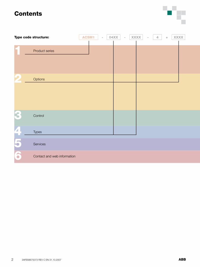
Product series
Options
Control
Types
Services
Contact and web information
1
2
3456
Type code structure: ACSM1 - 04XX - XXXX - 4 + XXXX
Contents

3ABB 3AFE68675073 REV C EN 31.10.2007
ABB high performance machinery drives, ACSM1
ABB high performance machinery drives ........................4Industries and applications .............................................4Features ........................................................................5Technical specifi cation ...................................................6ACSM1 drive .................................................................7
Internal options ...............................................................8Control and communication options .....................8
External options ..............................................................9Mains choke .........................................................9Mains fi lter (EMC) .................................................9Braking resistor ....................................................9
Control and programming ............................................10Drive tools ...................................................................11
Types, ratings and dimensions .....................................12
Services .......................................................................13
www.abb.com/motors&drives ......................................15
1
2
3456

4 ABB3AFE68675073 REV C EN 31.10.2007
ABB high performance machinery drives
ABB high performance machinery drives provide speed, torque and motion control for demanding machines. They can control induction, synchronous and asynchronous servo and high torque motors with various feedback devices. The compact hardware and programming fl exibility ensure the optimum solution. The innovative memory unit concept enables fl exible drive confi guration.Industries and applications
Industries and applications
The high performance machinery drives are ideal forPlastics and rubber
ExtrudersCalendersInjection moulding machinesWinders & unwinders Blow moulding machines
PrintingSheet-fed printingCommercial printingLabel printingWeb printingBindery machines
Paper & paperboard, fi lm & foil convertingCalenderingSlitterCoatingSheeterLaminatingWinders
■■
■
■
■
■
■■
■
■
■
■
■■
■
■
■
■
■
ABB high performance machinery drives
Material handlingCranesAutomatic storageElevatorsPick and place systemsConveyorsPalletising
TextileKnitting/weaving machinesNeedle punching machinesNon-woven machinesFibre processing machinesSpinning/speeder machinesTextile coating machines
Food and beverageConveyors, mixers and extrudersRolling, pressing and cuttingStampingSlicingBottling and labelingPackaging
Other industries and applicationsWoodworking machineryPlywood and chipboard industryFlying and rotary shearPackaging machineryWire & cable drawing machines
Highlights
For demanding machinery applicationsFor synchronous and induction motorsWide range of feedback interfacesSolution programming to extend drive functionsModular and compact designMemory unit for easy drive managementSafe Torque Off
■■
■
■
■
■
■
■■
■
■
■
■
■
■■
■
■
■
■
■
■■
■
■
■
■
■
■
■
■
■
■
■
ACSM1 - 04XX - XXXX - 4 + XXXX
5ABB 3AFE68675073 REV C EN 31.10.2007
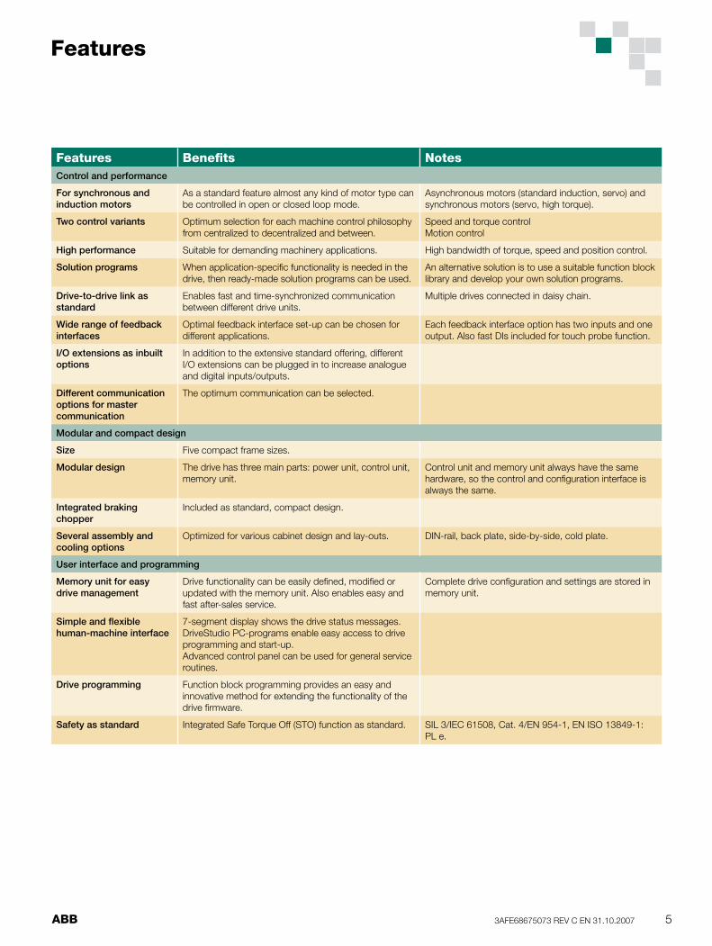
Features Benefi ts NotesControl and performance
For synchronous and induction motors
As a standard feature almost any kind of motor type can be controlled in open or closed loop mode.
Asynchronous motors (standard induction, servo) and synchronous motors (servo, high torque).
Two control variants Optimum selection for each machine control philosophy from centralized to decentralized and between.
Speed and torque controlMotion control
High performance Suitable for demanding machinery applications. High bandwidth of torque, speed and position control.
Solution programs When application-specifi c functionality is needed in the drive, then ready-made solution programs can be used.
An alternative solution is to use a suitable function block library and develop your own solution programs.
Drive-to-drive link as standard
Enables fast and time-synchronized communication between different drive units.
Multiple drives connected in daisy chain.
Wide range of feedback interfaces
Optimal feedback interface set-up can be chosen for different applications.
Each feedback interface option has two inputs and one output. Also fast DIs included for touch probe function.
I/O extensions as inbuilt options
In addition to the extensive standard offering, different I/O extensions can be plugged in to increase analogue and digital inputs/outputs.
Different communication options for master communication
The optimum communication can be selected.
Modular and compact design
Size Five compact frame sizes.
Modular design The drive has three main parts: power unit, control unit, memory unit.
Control unit and memory unit always have the same hardware, so the control and confi guration interface is always the same.
Integrated braking chopper
Included as standard, compact design.
Several assembly and cooling options
Optimized for various cabinet design and lay-outs. DIN-rail, back plate, side-by-side, cold plate.
User interface and programming
Memory unit for easy drive management
Drive functionality can be easily defi ned, modifi ed or updated with the memory unit. Also enables easy and fast after-sales service.
Complete drive confi guration and settings are stored in memory unit.
Simple and fl exible human-machine interface
7-segment display shows the drive status messages.DriveStudio PC-programs enable easy access to drive programming and start-up.Advanced control panel can be used for general service routines.
Drive programming Function block programming provides an easy and innovative method for extending the functionality of the drive fi rmware.
Safety as standard Integrated Safe Torque Off (STO) function as standard. SIL 3/IEC 61508, Cat. 4/EN 954-1, EN ISO 13849-1: PL e.
Features

6 ABB3AFE68675073 REV C EN 31.10.2007
Technical specifi cation
Main connectionsSupply voltage 3-phase 380 to 480 V +10 /- 15%
Frequency 50 to 60 Hz +/- 5%
Total harmonic distortion (THD)
A, B, C and D frames with optional mains choke (external) to meet limits acc. to EN 61000-3-2, Draft IEC 61000-3-12, IEC 61000-3-4. With E frame mains choke as standard.
DC connectionDC voltage level 436 to 712 V DC
Charging Internal
Motor connectionMotor types Asynchronous motors (standard
induction, servo) and synchronous motors (servo, high torque)
Output frequency 0 to 500 Hz
Switching frequency 2 to 16 kHz, 4 kHz as default.Output current derating above 4 kHz
Braking power connectionBraking chopper As standard in all types
Braking resistor External resistor connected to drive
Operating conditionsDegree of protection IP20 acc. to EN 60529;
Open Type acc. to UL 508.
Ambient temperature -10 to +55 °C, derating above 40 °C
Installation altitude 0 to 4000 m, derating above 1000 m
Relative humidity max. 95%
Climatic/environmental conditions
Class 3K3, 3C2 acc. to EN 60721-3-3. Oil mist, formation of ice, moisture condensation, water drops, water spray, water splashes and water jets are not permissible (EN 60204, Part 1).
Vibration Class 3M4 acc. to EN 60721-3-3
EMC(According to EN 61800-3)
Noise emission: - Standard: No fi ltering - With fi lter: Category C2
Functional safety Safe Torque Off function (STO acc. Draft EN 61800-5-2). IEC 61508: SIL 3EN 954-1: Category 4IEC 62061: SILCL 3EN ISO 13849-1: PL e
Compliance CE, UL, cUL, CSA, C-Tick
ACSM1 - 04XX - XXXX - 4 + XXXX

7ABB 3AFE68675073 REV C EN 31.10.20077
The ACSM1 series of high performance machinery drives offers versatile features for machinery applications. The ACSM1 covers power ratings from 0.75 to 110 kW (2.5 A to 210 A) in fi ve frame sizes.
Designed for machine builders
The ACSM1 is the optimum choice for machine builders. The ACSM1 can control with or without feedback induction motors, asynchronous and synchronous servo motors. It uses proven DTC motor control technology to guarantee high performance. The mechanical design is very compact and drives can be installed side-by-side. In addition to covering standard features there are three slots for control and communication options. Drive tools support commissioning, tuning and programming. The ACSM1 offers optimum selection for each machine control philosophy.
Modular and compact design
Five compact frame sizes 0.75 kW (1 Hp) to 110 kW (150 Hp) / 380 to 480 VIP20Supply AC or DC input from top (A, B, C, D
frames) or bottom (E frame)Motor and braking resistor connection from bottomInbuilt braking chopper as standard
Optimum assembly and cooling solutionsSide-by-side installationAir-cooled variant including support for DIN-rail
mounting or back plate mountingCold-plate variant for external cooling methodRemovable control terminals and power terminals
enables fast assembly and maintenance
Flexibility with different external optionsMains fi lters to meet EMC requirements.
As standard in the frame size E.Mains chokes to limit harmonic distortion (THD).
As standard in the frame size E.Braking resistors for various braking power needs
■■
■
■
■
■
■■
■
■
■
■■
■
■
Global compatibility with machinery environment and standards
Standard approvals for CE, UL, cUL, CSA, C-TickWith external mains fi lter: EN 61800-3, category
C2 (A-limits). As standard for the frame size E.Integrated Safe Torque Off (STO) function
according to SIL 3/IEC 61508 and Cat. 4/EN 954-1Coated boards as standard to meet environmental
requirement
Control and communication
Control interface with versatile standard connectionsDigital input/output: 6DI, 3DI/O, 1 relay outputAnalogue input/output: 2AI + 2AO Motor thermistor input (PTC/KTY)Drive-to-drive communication linkComplete drive confi guration and settings are
stored in memory unit
Scalability with different plug-in control optionsThree options slots for control optionsAnalogue and digital I/O extension modulesInterfaces for different feedback types
(TTL, Resolver, Sin/Cos, Endat, Hiperface, SSI)Master communication via fi eldbuses (PROFIBUS,
DeviceNet, CANopen and Ethernet)
■
■
■
■
■
■■
■
■
■
■
■■
■
■
■
ACSM1 driveHigh performance machinery drives

8 ABB3AFE68675073 REV C EN 31.10.2007
OptionsInternal
Options Data Slot 1 Slot 2 Slot 3
Analogue & digital extension
FIO-01 4 x DI/O, 2 x RO –
FIO-11 3 x AI, 1 x AO, 2 x DO –
Feedback interface
FEN-01 2 inputs (TTL incremental encoder), 1 output –
FEN-11 2 inputs (SinCos absolute, TTL incremental encoder), 1 output –
FEN-21 2 inputs (Resolver, TTL incremental encoder), 1 output –
Communication
FPBA-01 PROFIBUS – –
FCAN-01 CANopen – –
FDNA-01 DeviceNet – –
FENA-01 Ethernet/IP – –
Control and communication options
= option– = not available
Analogue and digital I/O extension
Feedback interface
Communication interface
Mains connection
DC connection
7-segment display
24VDC input
Relay output (1xRO)
Digital inputs and outputs (6xDI, 3xDI/O)
Analogue inputs (2xAI)
Thermistor input (PTC, KTY)
Analogue outputs (2xAO)
Drive-to-drive link (D2D)
Safe Torque Off (STO)
User interface (PC tools, control panel)
Braking resistor connection
Motor connectionMemory unit (MU)
X1External power input +24VI 124 V DC, 1.6 A GND 2
X2Relay output NO 3250 V AC / 30 V DC COM 42 A NC 5
X3+24 V DC* +24VD 1Digital I/O ground DGND 2Digital input 1 DI1 3Digital input 2 DI2 4+24 V DC* +24VD 5Digital I/O ground DGND 6Digital input 3 DI3 7Digital input 4 DI4 8+24 V DC* +24VD 9Digital I/O ground DGND 10Digital input 5 DI5 11Digital input 6 DI6 12+24 V DC* +24VD 13Digital I/O ground DGND 14Digital input/output 1 DIO1 15Digital input/output 2 DIO2 16+24 V DC* +24VD 17Digital I/O ground DGND 18Digital input/output 3 DIO3 19
X4Reference voltage (+) +VREF 1Reference voltage (-) -VREF 2Ground AGND 3Analogue input 1 (Current or voltage,selectable by jumper J1)
AI1+ 4AI1- 5
Analogue input 2 (Current or voltage,selectable by jumper J2)
AI2+ 6AI2- 7
AI1 current/voltage selection J1AI2 current/voltage selection J2Thermistor input TH 8Ground AGND 9Analogue output 1 (current) AO1 (I) 10Analogue output 2 (voltage) AO2 (U) 11Ground 12
X5Drive-to-drive link termination J3
Drive-to-drive link. See separate sectionbelow.
B 1A 2
BGND 3X6
Safe Torque Off. Both circuits must be closed for the drive to start. See separate section below.
OUT1 1OUT2 2IN1 3IN2 4
Control panel connectionMemory unit connection

9ABB 3AFE68675073 REV C EN 31.10.2007
OptionsExternal
Mains choke
The ACSM1 drive does not necessarily need a mains choke for operation. Each individual case should be checked to ascertain whether a mains choke needs to be installed. Mains chokes are typically used to:
reduce harmonics in the mains currentachieve a reduction in the r.m.s. mains current reduce mains disturbance and low-frequency inter-ferenceincrease the allowed DC bus continuous power
A mains choke series is available to meet differentsystem design needs. The frame size E has an inbuilt mains choke as standard.
Mains fi lter (EMC)
The EMC product standard (EN 61800-3 + Amendment A11 (2000)) covers the specifi c EMC requirements stated for drives (tested with motor and cable) within the EU. The new revision of 61800-3 (2004) product standard can be applied from now on, but latest from 1st October 2007. EMC standards such as EN 55011, or EN 61000-6-3/4, apply to industrial and household equipments and systems including drive component inside. Drive units complying with requirements of EN 61800-3 are always complient with comparable categories in EN 55011 and EN 61000-6-3/4, but not necessarily vice versa. EN 55011 and EN 61000-6-3/4 do not specify cable length nor require a motor to be connected as a load. The emission limits are comparable according to the following table, EMC standards.
■
■
■
■
Mains fi lters are available to meet category C2 level with the ACSM1 drive installation, including a motor with a max. 50 m cable. This level corresponds to the A limits for Group 1 equipment according to EN 55011.The frame size E has an inbuilt mains fi lter as standard.
Braking resistors
Depending on the application, an external braking resistor may be needed to convert the kinetic energy generated into thermal energy. A selection of resistors is available for different kinds of pulse duty performance. All braking resistors are equipped with a thermal sensor as standard.
EMC standards in generalEN 61800-3/A11 (2000), product standard
EN 61800-3 (2004),product standard
EN 55011, product family standard for industrial, scientifi c and medical (ISM) equipment
1st environment, unrestricted distribution
Category C1 Group 1 Class B
1st environment, restricted distribution
Category C2 Group 1 Class A
2nd environment, unrestricted distribution
Category C3 Group 2Class A
2nd environment, restricted distribution
Category C4 Not applicable

10 ABB3AFE68675073 REV C EN 31.10.2007
Control and programming
Scalable control and programming environment
Two control variants
Speed and torque control Motion control
Speed and torque control
Open and closed loop DTCSynchronous and asynchronous motorsIdeal for high bandwidth of speed or torque control application
Motion control
In addition to speed and torque controlHigh bandwidth of position and synchronization controlPoint-to-point positioning with extensible positioning profi le setsSynchronization (encoder feedback or drive-to-drive link)Register control based on fast probe inputsMultiple homing methods
Solution programming
In addition to multiple parameter programmable speed and position control functions, drive functionality
■
■
■
■
■
■
■
■
■
■
PC tools / DriveStudio, DriveSize
Motion control Technology functions, solution programs e.g.• Position sequence• CAM disk• Flying cut
POSITIONCONTROL
Speed & torque control
Technology functions, solution programs e.g.• Winder• Lift
SPEEDCONTROL
TORQUECONTROL M
Synchronous,asynchronous
ACSM1 / Memory unit ACSM1 / Power unit and control unit
can be easily modifi ed or extended using solution programming.
Standard function blocks to modify a basic control interface or make extensible PLC-tasks.Technology function blocks to meet machine-specif-ic application requirements, e.g. damping fi lters for demanding mechanical systems. Technology func-tion block libraries are optional.Solution programs, ready-made solutions for dedi-cated applications such as winding, lift control and fl ying cut applications using the corresponding technology function library. Easy to modify with parameters or additive function blocks.Drive functionality is defi ned and delivered with memory unit.
■
■
■
■
E

11ABB 3AFE68675073 REV C EN 31.10.2007
Pinch
Coupling
Idlerrollers
Driver rollers
Coupling
Cylinder
Coupling
Driver pulley
Belt
Driver pulley
Coupling
Leadscrew
Load
Load
Coupling
Pinion
Rack
Coupling
Core
Reeled material
Drive tools
DriveStudio
User-friendly PC environment both for simple drive commissioning tasks and for the more demanding drive tuning and programming tasks.
Commissioning and tuning toolsDrive overview screen for fast parameter and func-tion block navigation Parameter setting and signal monitoringData logger and on-line signal monitoring for drive tuning (multiple signal channels and triggering con-ditions)Back-up and restore tool for drive parameter cloning and life time supportCase sensitive helps with detailed drive parameter, event and function descriptions
Solution program composer Simple, easy-to-understand function block interface to drive fi rmware functions for signal monitoring and parameter settingSame interface enables the adding of user-defi ned function block programs even on the fastest time levels of the drive controlFunction block programming with standard function block libraryOptional and changeable technology function block library expands the variety of functionsProfessional programming environment: hierarchy levels, custom circuits, user parameters, copy protec-tion etc.
DriveCAM tool Multiple methods for designing axis profi le between reference axis and controlled drive axisUpload/download to drive memory, multiple profi les
■
■
■
■
■
■
■
■
■
■
■
■
Assistant control panel
The assistant control panel features a multilingual alphanumeric display for easy drive confi guration. It is an ideal tool for service engineers providing the following main features:
A large graphical displayExtremely easy to navigateSoft and convenient keysLocal control keys (start/stop/reference)Parameter setting and monitoringStatus and history data
The control panel is an external option and can be connected by cable to the ACSM1 drive. The panel mounting kit enables mounting of control panels on the cabinet doors or inside the control cabinet.
Sizing tool
DriveSize helps the machine designer to select the optimum ACSM1 drive, motor and gear combination for the required motion and speed profi les, and for typical mechanical applications.
Ready defi ned input sheets make it very easy to specify the dimensions of different kinds of linear or rotary movement mechanisms such as
lead screws rack and pinion combinations belt and pulley conveyor feed rollrotating table
■
■
■
■
■
■
■
■
■
■
■
■
12 ABB3AFE68675073 REV C EN 31.10.2007
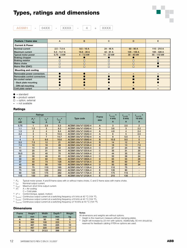
Types, ratings and dimensions
Ratings
Type codeFramesize
I2cont4k 6)
4 kHzA
I2cont8k 7)
8 kHzA
I2cont16k 8)
16 kHzA
PN1)
kWPN
1)
hpI2N
2)
AI2max
3)
A
0.75 1 2.5 5.3 ACSM1-04x4)x5)-02A5-4 A 3 2.5 21.1 1.5 3 6.3 ACSM1-04x4)x5)-03A0-4 A 3.6 3 2.21.5 2 4 8.4 ACSM1-04x4)x5)-04A0-4 A 4.8 4 2.42.2 3 5 10.5 ACSM1-04x4)x5)-05A0-4 A 6 5 2.53 3 7 14.7 ACSM1-04x4)x5)-07A0-4 A 8 5.5 34 5 9.5 16.6 ACSM1-04x4)x5)-09A5-4 B 10.5 9.5 5
5.5 7.5 12 21 ACSM1-04x4)x5)-012A-4 B 14 12 67.5 10 16 28 ACSM1-04x4)x5)-016A-4 B 18 13 7.511 15 24 42 ACSM1-04x4)x5)-024A-4 C 27 24 1815 20 31 54 ACSM1-04x4)x5)-031A-4 C 35 31 20
18.5 25 40 70 ACSM1-04x4)x5)-040A-4 C 44 35 2222 30 46 81 ACSM1-04x4)x5)-046A-4 C 50 38 2430 40 60 105 ACSM1-04x4)x5)-060A-4 D 65 55 2837 50 73 128 ACSM1-04x4)x5)-073A-4 D 80 60 3145 60 90 150 ACSM1-04x4)x5)-090A-4 D 93 65 3455 75 110 165 ACSM1-04x4)x5)-110A-4 E 110 75 -75 100 135 202 ACSM1-04x4)x5)-135A-4 E 135 90 -90 125 175 282 ACSM1-04x4)x5)-175A-4 E 175 115 -110 150 210 326 ACSM1-04x4)x5)-210A-4 E 210 135 -
Framesize
Height 1)
mmWidthmm
Depth 2)
mmWeight
kgA 364 90 146 3B 380 100 223 5C 467 165 225 10D 467 220 225 17E 700 313.5 398 67
Feature / frame size A B C D E
Current & Power
Nominal currentMaximum current
2.5 - 7.0 A5.3 - 14.7 A
9.5 - 16 A16.6 - 28 A
24 - 46 A42 - 81 A
60 - 90 A105 - 158 A
110 - 210 A165 - 326 A
Typical motor power 0.75 - 3 kW 4 - 7.5 kW 11 - 22 kW 30 - 45 kW 55 - 110 kWBraking chopperBraking resistorMains chokeMains fi lter (EMC)
Mounting and cooling
Removable power connectors – – –Removable control connectorsAir-cooled variant - Back plate mounting - DIN-rail mounting – – –
Cold plate variant – – –
= standard = product variant = option, external
– = not available
1) PN: Typical motor power. A and B frame sizes with or without mains choke, C and D frame sizes with mains choke.2) I2N: Nominal output current.3) I2max: Maximum short time output current. 4) x4) A = Air-cooling C = Cold plate5) x5) = Control (torque, speed, motion)6) I2cont4k: Continuous output current at a switching frequency of 4 kHz at 40 °C (104 °F).7) I2cont8k: Continuous output current at a switching frequency of 8 kHz at 40 °C (104 °F).8) I2cont16k: Continuous output current at a switching frequency of 16 kHz at 40 °C (104 °F).
NotesAll dimensions and weights are without options.1) Height is the maximum measure without clamping plates.2) Depth will increase by 23 mm with options. Additionally, 50 mm should be reserved for feedback cabling if FEN-xx options are used.
ACSM1 - 04XX - XXXX - 4 + XXXX
Ratings
Dimensions
13ABB 3AFE68675073 REV C EN 31.10.2007
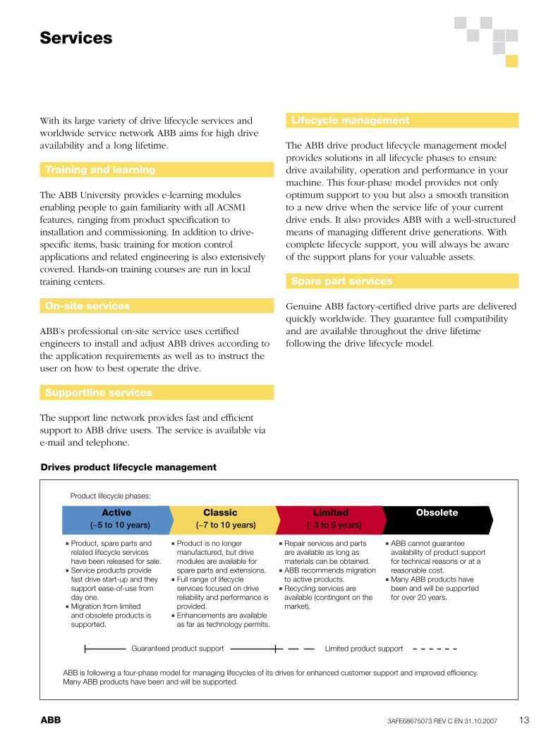
With its large variety of drive lifecycle services and worldwide service network ABB aims for high drive availability and a long lifetime.
Training and learning
The ABB University provides e-learning modules enabling people to gain familiarity with all ACSM1 features, ranging from product specifi cation to installation and commissioning. In addition to drive-specifi c items, basic training for motion control applications and related engineering is also extensively covered. Hands-on training courses are run in local training centers.
On-site services
ABB’s professional on-site service uses certifi ed engineers to install and adjust ABB drives according to the application requirements as well as to instruct the user on how to best operate the drive.
Supportline services
The support line network provides fast and effi cient support to ABB drive users. The service is available via e-mail and telephone.
Services
Lifecycle management
The ABB drive product lifecycle management model provides solutions in all lifecycle phases to ensure drive availability, operation and performance in your machine. This four-phase model provides not only optimum support to you but also a smooth transition to a new drive when the service life of your current drive ends. It also provides ABB with a well-structured means of managing different drive generations. With complete lifecycle support, you will always be aware of the support plans for your valuable assets.
Spare part services
Genuine ABB factory-certifi ed drive parts are delivered quickly worldwide. They guarantee full compatibility and are available throughout the drive lifetime following the drive lifecycle model.
Drives product lifecycle management
Active Classic Limited Obsolete
■ Product, spare parts and related lifecycle services have been released for sale.
■ Service products provide fast drive start-up and they support ease-of-use from day one.
■ Migration from limited and obsolete products is supported.
■ Product is no longer manufactured, but drive modules are available for spare parts and extensions.
■ Full range of lifecycle services focused on drive reliability and performance is provided.
■ Enhancements are available as far as technology permits.
■ Repair services and parts are available as long as materials can be obtained.
■ ABB recommends migration to active products.
■ Recycling services are available (contingent on the market).
■ ABB cannot guarantee availability of product support for technical reasons or at a
reasonable cost.■ Many ABB products have
been and will be supported for over 20 years.
Product lifecycle phases:
Guaranteed product support Limited product support
(~5 to 10 years) (~7 to 10 years) (~3 to 5 years)
ABB is following a four-phase model for managing lifecycles of its drives for enhanced customer support and improved effi ciency. Many ABB products have been and will be supported.
