1330-x02 printer operator’s manual - visara · 1330-x02 printer operator’s manual p/n...
TRANSCRIPT

1330-X02 Printer
Operator’s Manual
P/N 701333-004

ii 701333-004
ELUDEHCSNOISIVER/EUSSI
stnemmoC .oN.veR etaD
esaeleRlaitinI 100-333107 39/13/01
etadpUlacinhceT
eussieRetelpmoC
etadpUlacinhceT
etadpUlacinhceT
eussieRetelpmoC
eussieRetelpmoC
602157 100-
200-333107
100-602157
100-396657
300-333107
400-333107
49/13/30
49/01/60
49/51/90
49/02/21
69/20/20
99/11/60
IBM is a registered trademark of IBM Corporation.
© Copyright 1993, 1994, 1996 by MTX Corporation

701333-004 iii
This equipment complies with FCC regulations for EMI.
This equipment generates, uses, and can radiate radiofrequency energy, and, if not installed and used in accor-dance with the manual, may cause interference to radiocommunications. It has been tested and found to complywith the limits for a Class A computing device pursuant toSubpart J of Part 15 of FCC Rules, which are designed toprovide reasonable protection against such interferencewhen operated in a commercial environment. Operation ofthis equipment in a residential area is likely to cause inter-ference, in which case users, at their own expense, will berequired to take whatever measures may be necessary tocorrect the interference.
WARNING!

Page
701333-004 v
Table of Contents
Chapter 1. Introduction ............................................................................................1-1
Interfacing with the 1330 ................................................................................1-2A-Coax Attachment ....................................................................................1-2ASCII Attachment ......................................................................................1-3
Standard Features............................................................................................1-3Character Codes .........................................................................................1-3Color ...........................................................................................................1-4Paper Handling ...........................................................................................1-4Print Qualities .............................................................................................1-4Multiple Copies ..........................................................................................1-43270 Languages ..........................................................................................1-4Screen Sizes ...............................................................................................1-4Self-Diagnostic Testing ..............................................................................1-5Audible Alarm ............................................................................................1-5Programmed Symbols ................................................................................1-5IPDS ...........................................................................................................1-5
Optional Features ............................................................................................1-5Memory ......................................................................................................1-5Continuous Forms Module .........................................................................1-5Forms Handler Module...............................................................................1-6Printer Pedestal Stand .................................................................................1-6Forms Stand................................................................................................1-6
Related Manuals .............................................................................................1-6
Chapter 2. Preparing to Operate the 1330 ................................................................2-1
Inspecting the Package....................................................................................2-1Unpacking the Printer .....................................................................................2-1Installation Preparation ...................................................................................2-3Installing the Ribbon Cartridge .......................................................................2-4
Ordering Ribbons .......................................................................................2-4Installing a Shifting Ribbon........................................................................2-4Installing a Nonshifting Ribbon .................................................................2-7
Connecting the Printer to a Power Source ......................................................2-8Power Cable Requirements ........................................................................2-8
Connecting the Coax Cable ............................................................................2-9Connecting a Parallel or Serial Cable ...........................................................2-10
Connecting a Parallel Cable .....................................................................2-10Connecting a Serial Cable ........................................................................2-10
Powering on the 1330 ...................................................................................2-11Forms Specifications.....................................................................................2-11Installing the Forms – Continuous Forms Module ........................................2-17
Setting the Platen Gap Lever ....................................................................2-20Installing the Forms Handler Module ...........................................................2-21
Installing Forms Using the DOD Option ..................................................2-21Installing Forms Using the DID Option ...................................................2-23
Chapter 3. Operator Control Panel ...........................................................................3-1
The Status Display ..........................................................................................3-1Cu ...............................................................................................................3-2S/C/A ..........................................................................................................3-2

vi 701333-004
Table of Contents
Page
Operating Mode ..........................................................................................3-2Form Device ...............................................................................................3-2Emulation Mode .........................................................................................3-2Datastream Mode/Interface Type................................................................3-3Status Message ...........................................................................................3-3
The Keypad .....................................................................................................3-3Key Functions .............................................................................................3-3
Chapter 4. Configuring the 1330 in 3270 Mode ........................................................4-1
Configuration Procedure .................................................................................4-1Using the Keys ...........................................................................................4-1Getting into the Menu Mode ......................................................................4-1Scrolling Through Menu Selections ...........................................................4-2Selecting a Menu Option ............................................................................4-4Leaving Menu Mode ..................................................................................4-4
The Configuration Options .............................................................................4-5100 Page Format .........................................................................................4-5200 Font & Print Quality ............................................................................4-8300 Compatibility .....................................................................................4-13400 Printer Setup ......................................................................................4-17500 Communication .................................................................................4-25600 Attachment.........................................................................................4-27700 Extended Keypad ...............................................................................4-28800 Program Symbol ................................................................................4-33900 Vital Product Data..............................................................................4-34
Chapter 5. Configuring the 1330 in ASCII Mode ....................................................5-1
Configuration Procedure .................................................................................5-1Using the Keys ...........................................................................................5-1Getting into the Menu Mode ......................................................................5-1Scrolling Through Menu Selections ...........................................................5-2Selecting a Menu Option ............................................................................5-4Leaving Menu Mode ..................................................................................5-4
The Configuration Options .............................................................................5-5100 Page Format .........................................................................................5-5200 Font & Print Quality ............................................................................5-7300 Compatibility .....................................................................................5-10400 Printer Setup ......................................................................................5-14500 Communication .................................................................................5-22600 Attachment.........................................................................................5-26700 Extended Keypad ...............................................................................5-27
Chapter 6. Operating the 1330 .................................................................................6-1
Setting the Print Format ..................................................................................6-1Specific Operating Procedures ........................................................................6-2
Printing the Setup Line ...............................................................................6-2Adjusting the Top of Form Position............................................................6-3Storing Printer Configuration Values ..........................................................6-3
General Operating Procedures ........................................................................6-4Reprinting the Print Buffer .........................................................................6-4

Table of Contents
701333-004 vii
Page
Requesting a Host Application Program in SCS Mode ..............................6-5Halting a Print Operation in SCS Mode .....................................................6-5
Chapter 7. Maintaining the 1330..............................................................................7-1
Ventilation .......................................................................................................7-1Cleaning the Printer ........................................................................................7-1Replacing the Ribbon .....................................................................................7-1Replacing the Print Head ................................................................................7-1Checking Character Width and Print Registration ..........................................7-5
Checking Character Width .........................................................................7-6Checking Print Registration .......................................................................7-7
Chapter 8. Error Detection and Recovery ................................................................8-1
Types of Errors ................................................................................................8-1Intervention Required Conditions...............................................................8-1General Error Conditions ...........................................................................8-2Unusual Error Conditions ...........................................................................8-2
Appendix A. Status and Error Message Chart ........................................................A-1
Appendix B. Programming Notes ........................................................................... B-1
Programming in SCS Control Codes (Non-IPDS) ......................................... B-1Set Print Density ............................................................................................ B-2Page Presentation Media ................................................................................ B-2Using Host Controlled Color/Highlighting/Symbol Set ................................ B-3
LU1 Mode ................................................................................................. B-3LU3 Mode ................................................................................................. B-4
Programming in IPDS Data Stream ............................................................... B-7Initialization Defaults ................................................................................ B-7Command Format ...................................................................................... B-9IPDS Command Codes ............................................................................ B-10Device Control Function Set Commands ................................................ B-10Text Function Set Commands.................................................................. B-11Image Function Set Commands ............................................................... B-11Graphics Function Set Commands .......................................................... B-11Bar Code Function Set Commands ......................................................... B-12Overlay Function Set Commands ............................................................ B-12Page Segment Function Set Commands .................................................. B-12Loaded Font Function Set Commands..................................................... B-13
Using Escape Sequences in 3270 Mode....................................................... B-13Selecting the Escape Character ............................................................... B-14Selecting Escape Codes ........................................................................... B-17Using the Bar Code Feature .................................................................... B-19Using Bar Code Escape Sequences ......................................................... B-21Calculating Checksums ........................................................................... B-24Print Optical Character Reader Parameter ............................................... B-24
1330 Commands in ASCII Mode ................................................................. B-27Using Proprinter Commands in ASCII Mode .............................................. B-27
Print Mode Commands ............................................................................ B-27Horizontal Movement Commands ........................................................... B-29

viii 701333-004
Table of Contents
Page
Horizontal Tabbing Commands ............................................................... B-30Vertical Movement Commands ............................................................... B-30Vertical Tabbing Commands.................................................................... B-31Page Formatting Commands ................................................................... B-32Bit Image Graphics Commands............................................................... B-32Font Control and Download Commands ................................................. B-34Character Set Selection Commands ........................................................ B-35Language Set Selection Commands ........................................................ B-35Set Initial Condition Commands ............................................................. B-36Miscellaneous Commands ....................................................................... B-37
Using TI-810 Command Functions in ASCII Mode .................................... B-38Escape Command Strings ........................................................................ B-39
Using Escape Sequences with ANSI Bar Codes .......................................... B-40
Appendix C. Character Sets ..................................................................................... C-1
Appendix D. Consumables .....................................................................................D-1
Ribbons ..........................................................................................................D-1Print Heads ....................................................................................................D-1
Appendix E. Character Count Record..................................................................... E-1
Index...................................................................................................................Index-1

701333-004 ix
Page
List of Illustrations
Figure 2-1. Unpacking the 1330 .................................................................2-2Figure 2-2. Foam Shipping Tube ................................................................2-3Figure 2-3. Shifting Ribbon Cartridge ........................................................2-5Figure 2-4. Platen Gap Lever ......................................................................2-5Figure 2-5. Disengaging the Ribbon Shifter Guide ....................................2-6Figure 2-6. Nonshifting Ribbon Cartridge ..................................................2-7Figure 2-7. Installing the AC Power Cord ..................................................2-9Figure 2-8. Connecting the Coax Cable .....................................................2-9Figure 2-9. Connecting a Parallel or Serial Cable ....................................2-10Figure 2-10. Forms Specifications - Physical Requirements ......................2-12Figure 2-11. Forms Specifications - Print Positioning ................................2-13Figure 2-12. Print Positioning - Continuous Forms ....................................2-14Figure 2-13. Print Positioning - Single Part Forms.....................................2-15Figure 2-14. Paper Feed Slots .....................................................................2-17Figure 2-15. Open Tractor Door .................................................................2-18Figure 2-16. Flipping the Tractor Lever .....................................................2-18Figure 2-17. Inserting Paper - Continuous Forms Module .........................2-19Figure 2-18. Platen Gap Lever ....................................................................2-20Figure 2-19. Forms Handler Module (DOD Option) ..................................2-21Figure 2-20. DOD Option with Roller Drive ..............................................2-23Figure 2-21. Forms Handler Module (DID Option) ...................................2-23Figure 2-22. Inserting Paper - Forms Handler Module ...............................2-24Figure 2-23. DID Option with Roller Drive ...............................................2-25Figure 3-1. 1330 Operator Control Panel ...................................................3-1Figure 3-2. Status Display ..........................................................................3-1Figure 4-1. Aligned and Unaligned Dots in Characters ............................4-19Figure 5-1. Aligned and Unaligned Dots in Characters ............................5-16Figure 7-1. Replacing the Print Head .........................................................7-3Figure 7-2. Carriage Restraining Hook ......................................................7-3Figure 7-3. Mounting Screws .....................................................................7-4Figure 7-4. Carriage - Side View ................................................................7-5Figure 7-5. Proper Print Registration ..........................................................7-5Figure 7-6. Increase Print Registration Value .............................................7-7Figure 7-7. Decrease Print Registration Value ............................................7-8Figure B-1. Escape Sequence Structure ................................................... B-13Figure B-2. Table for Selecting Escape Character ................................... B-15Figure B-3. Escape Codes ........................................................................ B-18Figure B-4. Bar Code Types ..................................................................... B-20Figure B-5. Calculating New Line Characters ......................................... B-23Figure B-6. OCR-A Character Set ........................................................... B-25Figure B-7. OCR-B Character Set ........................................................... B-26

701333-004 1-1
Chapter 1. Introduction
The MTX 1330 Printer is designed for high-volume printing and combines high reliabilitywith convenient features such as modular paper handling, a 4-line, 80-character LCDthat displays menus, an automatic forms thickness adjustment, and self-diagnosticmessages. The 1330 produces clear, precise printing on up to six-part forms,accommodates continuous forms and cut sheet paper, and operates quietly for officeenvironments.
A serial dot matrix bidirectional impact printer, the 1330 is available in one model:
• 1330-X02
This model prints in four qualities. The maximum print speeds (at 10 CPI in monochrome)in each quality are as follows (CPS = characters per second):
tfarDtsaF*ytilauQ
gnissecorPataDytilauQ
gnissecorPataDytilauQtxeT
retteLraeNytilauQ
SPC005 SPC004 SPC052 SPC521
The 1330 is available with an 18-wire-shifting ruby print head. Output can bemonochrome, four colors or 8 colors, depending on the ribbon cartridge installed.Comprehensive graphics support is offered through All Points Addressable (APA)Programmed Symbols, as well as Intelligent Printer Data Stream (IPDS). The 1330 alsosupports APL and 39 international character sets.
The 1330 supports several attachment cards that offer the highest possible flexibility foryour corporate printing strategy. Some of the attachment cards feature a 3270 interfaceport, and parallel and serial ASCII input ports, thereby enabling automatic printer sharingbetween 3270 hosts and personal workstations. (See table at the top of the followingpage.)
*Fast Draft is only available in 3270 mode.

1-2 701333-004
Introduction
sdraoBtnemhcattA stnemnorivnEnoitacinummoC
xaoC sretpadaxaoC-Ahtiwsrellortnocdnastsoh0723-
)lauD(IICSA/xaoC sretpadaxaoC-Ahtiwsrellortnocdnastsoh0723-,).cte,004SAMBI(sretupmocinim,semarfniaM-
htiwsretupmoclanosrepdna,snoitatskrowlaires234SR/232SRdnalellarapscinortneC
secafretniehtneewtebgnirahsretnirpgnihctiwsotuastroppuS
.tsohIICSAdna0723
IICSA MBI(sretupmocinim,snoitatskrow,semarfniaM-htiwsretupmoclanosrepdna,).cte,004SA
laires234SR/232SRdnalellarapscinortneCsecafretni
Interfacing with the 1330
A-Coax Attachment
The 1330 Coax can be attached to the following controllers via an A-type coax cable:
• Telex 046, 076, 274, and 276 controllers
• Memorex 2076, 2174, and 2274 controllers
• Memorex Telex 1174, 1274, and 1374 controllers
• IBM 3174, 3274, and 3276 controllers with “A” terminal ports
• IBM 3694 Document Processor
• IBM 4321, 4331, 4341, and 4361 processors through the standard display/printeradapter or expansion feature
• IBM 9370 processor
Emulation
The following printer emulations are available as standard features on the 1330 Coax:
• IBM 3268 – Emulates a non-IPDS IBM 4224 printer with IBM 3628 programmedsymbols
• IBM 4224 – Emulates an IBM 4224 printer
• IBM 4230 – Emulates an IBM 4230 printer
• 2124 – Emulates a non-IPDS IBM 4224 printer with IBM 3268 programmed symbolsand supports escape codes to select bar codes, formatting, fonts, highlighting, OCRprinting, and so on

701333-004 1-3
Introduction
ASCII Attachment
With an ASCII attachment, the following features are available on the 1330.
Interfaces
The following interfaces are software selectable from the front panel:
• Centronics parallel
• RS-232C
• RS-422
Emulation
The following printer emulations are available as standard features on the 1330 ASCII:
• IBM Proprinter III and III XL
• TI-810 modified
Character Codes
In ASCII mode, the American Standard Code for Information Exchange (ASCII) characterset is recognized by the 1330. See Appendix C, “Character Sets,” for information aboutASCII character sets.
Print Buffer
In ASCII mode, the print buffer is a reserved area of memory for storing incoming databefore it is printed. The buffer size is operator selectable for 2K, 8K, 16K, or 32K bytes.
ASCII Languages
The 1330 supports international languages through the use of its internal PC characterset. Selection is made from the front panel during printer configuration.
Standard Features
Standard features of the 1330 are described below. Information for using these printingcapabilities is presented in subsequent chapters of this manual.
Character Codes
In 3270 mode, the Extended Binary Coded Decimal Interchange Code (EBCDIC)character set is recognized by the 1330, as well as the SNA Character String (SCS). SeeAppendix B of this manual for character code charts for SCS support.

1-4 701333-004
Introduction
Color
The 1330 can print in monochrome or color, using an operator installable recirculatingcloth ribbon cartridge. Two monochrome ribbons, a 4-color accent ribbon (black, red,blue, and green), and a subtractive 8-color ribbon (black, red, blue, green, yellow, magenta,cyan, and brown) are available.
Paper Handling
The 1330 comes standard with pull tractors for continuous forms feeding, and allows foreasy paper loading at the front of the printer. Pinfeed forms from 3 to 14 inches (7.6 to35.6 cm) long and 3 to 15 inches (7.6 to 38.1 cm) wide can be used. This configuration isespecially suited for a large volume of work or work that requires little operatorintervention.
Print Qualities
The 1330 can print in four qualities:
• Fast Draft Quality (FD) (available only in 3270 mode)
• Data Processing (DP)
• Data Processing Text (DP Text)
• Near Letter Quality (NLQ)
All print qualities are selectable via the operator control panel.
Multiple Copies
The 1330 can print multiple copies, one original plus five copies, total thickness not toexceed 0.025 inch (0.64 mm). The recommended maximum thickness for multipart formsis 0.018 inch (0.46 mm).
3270 Languages
The 1330 enables the operator to select from 39 international language character sets.Selection is made during printer configuration. The attached control unit should beconfigured for the same language.
Screen Sizes
Any of the following display buffer sizes can be selected for print operation:
• 1920 bytes
• 2560 bytes

701333-004 1-5
Introduction
• 3440 bytes
• 3564 bytes
The size can be selected by the operator during configuration.
Self-Diagnostic Testing
The 1330 has a self-diagnostic ability to ensure that the printer is in good workingcondition. If an error condition is encountered, the 1330 informs the operator by displayingan error message on the control panel. Should this occur, refer to the error message chartin Appendix A of this manual.
Audible Alarm
The 1330 features an audible alarm that sounds when the printer needs operator assistance(such as when the paper is skewed or out). In this situation it will continue to beepintermittently, unless it is disabled.
Programmed Symbols
In 3270 mode, six symbol sets are operator configurable either as six single plane sets oras three single plane sets and one triple plane set.
IPDS
Intelligent Printer Data Stream (IPDS) is a structured field datastream for managingprinting processes and data objects. IPDS uses All Points Addressability (APA) to enablethe user to position text, graphics, image data, overlays, and bar codes at any definedpoint on a printed page. Extended memory is recommended for graphics applications.
Optional Features
The following optional accessories are available for the 1330. These items can be orderedthrough your sales representative.
Memory
This feature adds 512K bytes of RAM memory to the standard 128K bytes of memoryfor a total of 640K bytes. The extra memory is recommended for the followingapplications: IPDS, programmed symbols, ASCII graphics, ASCII downloaded fonts,and dual host (auto-switching) operations.
Continuous Forms Module
The continuous forms module provides the operator with a reliable way of feeding the1330 with continuous forms.
1-6 701333-004
Introduction
Forms Handler Module
The Forms Handler module is operator installable in the front of the printer to verticallyposition forms. The module’s forms tractors are adjustable for two options:
• Document on Demand (DOD) option – used for continuous forms
• Document Insertion Device (DID) option – used for cut sheet/single sheet forms
Printer Pedestal Stand
The pedestal stand is designed so that the printer can be securely seated. The formssupply is placed in the stand’s paper compartment and feeds into the front of the 1330from below.
Forms Stand
The forms stand is placed behind the printer to hold both new and printed fanfold forms.
Related Manuals
Appendix D of this manual contains programming information for special 1330 escapecodes.
For more information on printer control codes in Appendix B, see the IBM 4224 PrinterProduct and Programming Description Manual, GC31-2551; IBM 4230 Printer Productand Programming Description Manual, GC40-1701-00; IBM 3270 Information andDisplay System, GA23-0061; IBM 3268 Printer Models 2 and 2C Description, GA27-3268; IBM Proprinter III and IIIXL Guide to Operations, SA34-2065-1; IBM ProprinterFamily Technical Reference, SC31-2589-3; and the ANSI Standard X3.64-1979.

701333-004 2-1
Chapter 2. Preparing to Operatethe 1330
The 1330 printer has been designed for customer setup and preliminary check. Pleaseread this chapter before you try to install or relocate your 1330.
Inspecting the Package
When the packaged 1330 printer arrives, inspect the carton for physical damage beforeunpacking it. If the carton is damaged, do not open it. Notify the Traffic Department oryour sales representative, as appropriate.
Also call the delivery carrier to request examination of the damage. The carrier is requiredto complete and sign a damage report form.
If you do not see any damage, unpack the printer according to the following instructions.
Unpacking the Printer
Refer to Figure 2-1 and follow these steps to unpack the 1330:
CautionThe 1330 weighs 66 pounds (29.9 kg). Two people may be required to move the printerto its operating location.
1. Move the packaged printer to the work area and place the carton in an upright position.
2. Remove the packing list envelope from the outside of the box.
3. Open the flaps to the top of the box.
4. Remove the operator’s manual from the top of the printer.
5. Remove the continuous forms module feature (if ordered) located on top of theprinter.
6. Remove the printer from the box and remove the foam end caps and the bag fromthe printer.
7. Remove the protective film from the top of the printer.
8. Lift the printer cover and remove the ribbon and power cord.

2-2 701333-004
Preparing to Operate the 1330
Continuous FormsModule Feature
Right End Cap
Left End Cap
Packing List Envelope
Figure 2-1. Unpacking the 1330

701333-004 2-3
Preparing to Operate the 1330
Shipping Tube
Figure 2-2. Foam Shipping Tube
9. The carriage on the 1330 is restrained by a foam shipping tube to prevent shifting duringshipping. Before installing the printer, remove this tube, illustrated in Figure 2-2.
CautionFailure to remove the carriage shipping tube before turning on the 1330 may result indamage to the printer.
Installation Preparation
The location for the 1330 must meet the following physical and environmentalrequirements:
:rewoP esahpelgnis,zH36-74taCAV462-09
:ecnaraelC sedisllano)mc2.51(ni6
:snoisnemiD ediw)mc5.56(ni8.52hgih)mc5.13(ni4.21peed)mc8.74(ni8.81
:egnaRerutarepmeTgnidnuorruS )C6.04-01(F501-05
:ytidimuHevitaleR )gnisnednocnon(%08ot%8
After unpacking the 1330, you are now ready to begin installing it.

2-4 701333-004
Preparing to Operate the 1330
Installing the Ribbon Cartridge
A monochrome ribbon cartridge is shipped with the 1330. Remember that if you have amonochrome ribbon installed, the 1330 will print in one color only. A multitrack colorribbon cartridge must be installed to allow printing in different colors.
Ordering Ribbons
You can use a Shifting ribbon or a Nonshifting ribbon in the 1330-X02. The ribbons havethe same character life and for monochrome printing can be used interchangeably.
CautionUse only approved ribbons that are available from MTX. Third party ribbons may not becompatible, resulting in improper operation and decreased print head life.
To order additional ribbon cartridges for the 1330-X02, contact your MTX SalesRepresentative. Request the following ribbon cartridge part number(s):
epyTnobbiR N/PXTM
gnitfihS–)tneccA(roloC-4 200-078559
gnitfihsnoN–emorhconoM 100-263559
Following are instructions for installing each ribbon type.
Installing a Shifting Ribbon
This section explains how to install a Shifting ribbon cartridge. You will need to install anew ribbon when the existing ribbon wears out. Refer to Figure 2-3.
1. Make sure that the printer’s Power switch is in the O (OFF) position. Unplug thepower cord from the outlet.
2. Raise the printer cover.
3. Set the platen gap lever away from the platen (toward you) as far as it will go (seeFigure 2-4).
4. Slide the print head to the middle of the printer.
CautionThe print head may be hot. To move it, grasp the print head drive belt.

701333-004 2-5
Preparing to Operate the 1330
Removable Corner Guides
Ribbon Shifter Guide
Ribbon Stop (REMOVEAFTER INSTALLATION)
Mounting Clip
Mounting Clip
Ribbon DriveGear Knob
Figure 2-3. Shifting Ribbon Cartridge
Ribbon Shifter ButtonRibbon Shifter Button
Platen Gap Lever
Figure 2-4. Platen Gap Lever
5. If you are replacing the ribbon cartridge, grasp both sides of the ribbon shifter guide,as illustrated in Figure 2-5, and gently bend the sides toward the rear of the printer.The ribbon shifter guide will disengage. Lift it away from the printer.

2-6 701333-004
Preparing to Operate the 1330
Ribbon Shifter Guide
Figure 2-5. Disengaging the Ribbon Shifter Guide
6. If you are replacing the ribbon cartridge, lift out the old cartridge and remove theplastic corner guides. Reinstall the new corner guides (they are packed in the newribbon cartridge package) over the corner guide brackets.
7. Snap the new ribbon cartridge into place. Make sure that the tabs on the front andback of the cartridge snap into the slots on the ribbon cartridge bracket.
8. Pull the ribbon stop out of the cartridge and put the stop aside for later use.
9. Install the ribbon shifter guide by positioning it above the nose of the print head,then press the guide down until it rocks into place on the ribbon shifter buttons. Ifthe ribbon shifter guide is properly installed, it will rotate smoothly.
CautionMake sure that the barrel fits snugly against the print head nosepiece. Otherwise, it willnot shift properly.
10. Use the tapered end of the ribbon stop to route the ribbon around the right and leftcorner guides.
11. Turn the ribbon drive gear knob counterclockwise several times to make sure theribbon is feeding properly.
12. Slide the print head to the far left and reset the platen gap lever to the appropriateposition to accommodate the thickness of the forms. If necessary, refer to “Settingthe Platen Gap Lever” later in this chapter. Close the printer cover.
CautionIf the platen gap adjustment is set too close to the paper, the life of the print head will bereduced and the print head may be damaged.
13. Connect the printer to a power source, as explained later in this chapter.

701333-004 2-7
Preparing to Operate the 1330
Installing a Nonshifting Ribbon
Follow these steps to install or replace a Nonshifting ribbon cartridge. Refer to Figure 2-6.Note that the Nonshifting ribbon is monochrome only.
1. Turn the printer off and unplug the power cord from the outlet.
2. Raise the printer cover.
3. Set the platen gap lever away from the platen (toward you) as far as it will go (seeFigure 2-4).
WarningThe print head may be hot. To move it, grasp the print head drive belt.
4. Slide the print head to the middle of the printer.
5. Grasp the ribbon guide, as illustrated in Figure 2-6, and lift it from the print head.
Corner GuideRibbon Advance Knob
Ribbon Guide
Cassette Tabs
RibbonTurning Post
Corner Guide
Figure 2-6. Nonshifting Ribbon Cartridge
6. Remove the used corner guides. The new corner guides are attached to the newribbon. (On Shifting ribbons, the corner guides are separate.)
7. Release the left end of the cartridge first. Push back the metal spring clip on theprinter, and squeeze the cassette tabs. Lift the left end of the cartridge clear, thenpush the metal spring clip forward to release the right end.
8. Pull the ribbon guide from the body of the new cartridge and make sure the ribbon isnot twisted.
9. Seat the cartridge onto the platform. Press down along the top of the cartridge toensure that it is firmly seated, with the cassette tabs snapped into the openings in theplatform.
10. Slide the plastic corner guides onto the ribbon turning posts while making sure theribbon is not twisted. Make sure that the corner guides are pressed all the way down.

2-8 701333-004
Preparing to Operate the 1330
11. Snap the ribbon guide onto the print head. The ribbon guide must fit securely on theribbon shifter buttons shown in Figure 2-4. Make sure the ribbon is not twisted.
12. Take up the ribbon slack by turning the ribbon advance knob in the direction of thearrow.
CautionIf the platen gap adjustment is set too close to the paper, the life of the print head will bereduced and the print head may be damaged.
13. Close the printer cover.
14. Connect the printer to a power source, as explained in the next section.
Connecting the Printer to a Power Source
Avoid connecting the 1330 to a power source shared by devices such as motors or fansthat may cause low fluctuating voltage or that may introduce noise into the power supply.Unstable voltage can cause the printer to operate erratically.
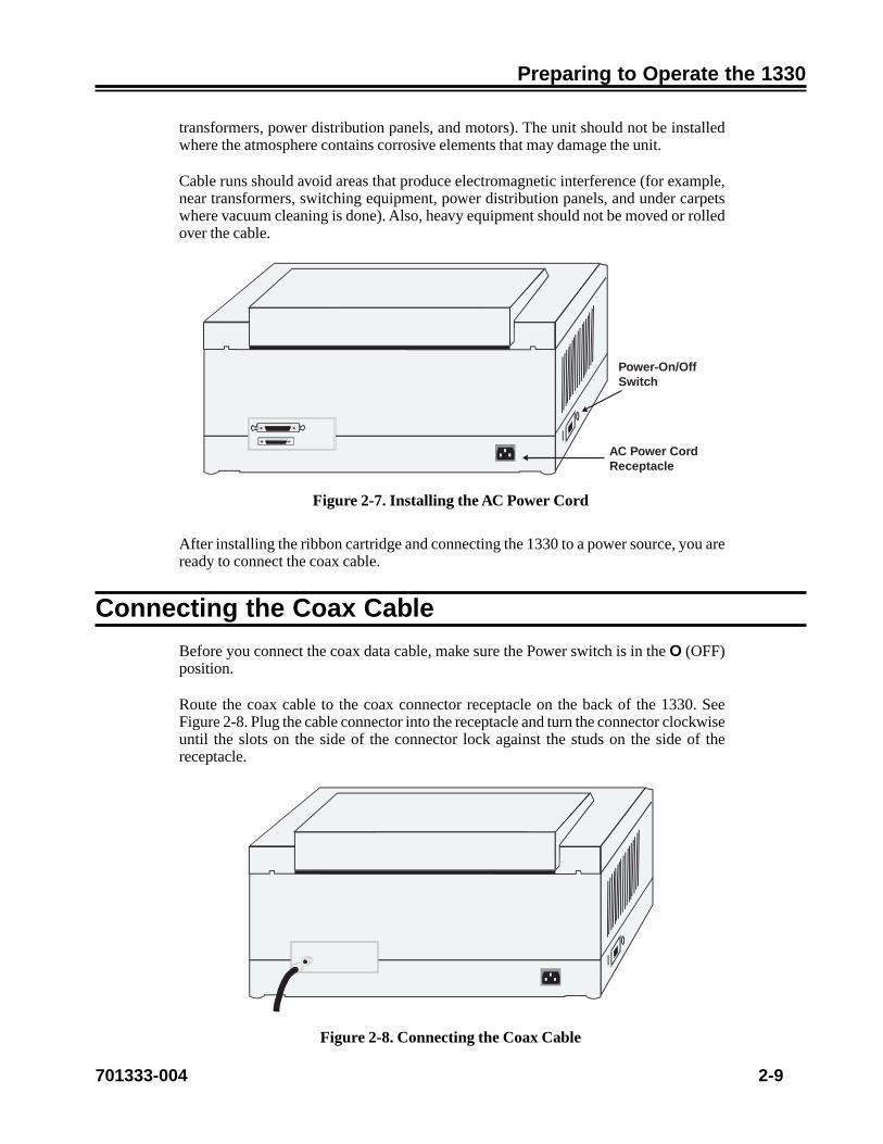
Uncoil the AC power cord. Plug the socket end of the power cord into the receptacle onthe back of the 1330 (see Figure 2-7), then plug the connector end of the power cord intothe proper AC outlet.
Power Cable Requirements
For operation at 100-120V: The power cable required for domestic units is a UL listed,CSA certified, 18/3 AWG, type SVT or SJT cable (15-foot [4.6-meter] maximum). It isterminated on one end by a 125V, 15A grounding type attachment connector. It isterminated at the other end by a 125V, 15A parallel blade, grounding type attachmentplug.
For operation at 200-240V: The power cable required for domestic units is a UL listed,CSA certified, 18/3 AWG, type SVT or SJT cable (15-foot [4.6-meter] maximum). It isterminated on one end by a 250V, 15A grounding type attachment plug body. It isterminated at the other end by a 250V, 15A tandem blade, grounding type attachmentconnector.
The power cable required for international units is an 18/3 AWG, type SJT cable (15-foot [4.6-meter] maximum). It is terminated on one end by a 250V, 15A grounding typeattachment plug body. It is terminated at the other end by a 250V, 15A grounding typecord connector. The cord set is marked HAR to signify appropriate safety approvals.
The installation site must provide a properly wired and grounded power outlet. Circuitsconnected to air conditioners and devices that generate significant transient electricalnoise should be avoided.
Electrostatic discharge in the vicinity of the unit should be minimized by avoiding highresistance floor material and carpeting that does not have antistatic properties, avoidingthe use of plastic seats and covers, and avoiding low humidity levels. The unit should belocated away from areas that generate electromagnetic interference (for example,
701333-004 2-9
Preparing to Operate the 1330
transformers, power distribution panels, and motors). The unit should not be installedwhere the atmosphere contains corrosive elements that may damage the unit.
Cable runs should avoid areas that produce electromagnetic interference (for example,near transformers, switching equipment, power distribution panels, and under carpetswhere vacuum cleaning is done). Also, heavy equipment should not be moved or rolledover the cable.
Power-On/OffSwitch
AC Power CordReceptacle
Figure 2-7. Installing the AC Power Cord
After installing the ribbon cartridge and connecting the 1330 to a power source, you areready to connect the coax cable.
Connecting the Coax Cable
Before you connect the coax data cable, make sure the Power switch is in the O (OFF)position.
Route the coax cable to the coax connector receptacle on the back of the 1330. SeeFigure 2-8. Plug the cable connector into the receptacle and turn the connector clockwiseuntil the slots on the side of the connector lock against the studs on the side of thereceptacle.
Figure 2-8. Connecting the Coax Cable

2-10 701333-004
Preparing to Operate the 1330
Connecting a Parallel or Serial Cable
To comply with FCC regulations, use one of the following cables:
• Parallel cable – MTX P/N 956588-001 (36-pin, 6 ft. EIA).
• RS-232 serial cable – This is available as P/N 957520-010 (10 feet). For other RS-232or RS-422 applications, use locally available cables.
Before you connect the cable, make sure the Power switch is in the O (OFF) position.
Connecting a Parallel Cable
Push the male end of the parallel cable into the parallel receptacle on the back of the1330 (see Figure 2-9). Push the wire guards, located at each end of the receptacle, in,over the cable end, to hold the cable in place.
Connecting a Serial Cable
Loosen the screws at each end of the serial receptacle on the back of the 1330 (see Figure2-9). Push the male end of the serial cable into the serial receptacle. Tighten the screwsto hold the cable in place.
Wire Guards
Parallel ReceptacleSerial Receptacle
Screws
Figure 2-9. Connecting a Parallel or Serial Cable
701333-004 2-11
Preparing to Operate the 1330
Powering on the 1330
Turn the printer on by setting the Power switch to the | (ON) position (see Figure 2-7).
When the printer is powered on, BASIC ASSURANCE TEST IN PROGRESS will appearin the display window. The Basic Assurance Test (BAT) tests various components of the1330 and ensures that the printer is ready for operation. The current status of the test inprogress is displayed in the bottom row. If an error condition is encountered during theBAT, the BAT will halt and the error message will be displayed. For a list of error messagesand recovery procedures, refer to Appendix A of this manual.
Note: If you have been following the procedures for printer installation as presentedin this chapter, the display will indicate that there is no paper in the printer.Continue to follow these procedures.
When the BAT is completed successfully (within a few seconds), the READY messagewill appear in the display window. In 3270 mode, if communications have been establishedwith the host system, Cu will display. If communications have not been established withthe host, the display will read READY, and Cu will disappear in about 30 seconds.
The next step is to check your forms against the 1330 forms specifications.
Forms Specifications
Before installing the forms, you should review the forms you intend to use to make surethey meet 1330 specifications. Figures 2-10 through 2-13 show these specifications.Specifications are given for the two types of form feed mechanism available for the1330, the Continuous Forms module and the Forms Handler module (with both theDocument on Demand [DOD] option and Document Insertion Device [DID] option).

2-12 701333-004
Preparing to Operate the 1330
suounitnoC DOD DIDeludoMsmroF noitpO noitpO
epyTeludoM A B B
smroFfoepyT suounitnoC suounitnoC elgniS
htgneLmumixaM ni0.41 ni0.41 ni0.41
mc6.53 mc6.53 mc6.53muminiM ni0.3 ni0.3 ni5.7
mc6.7 mc6.7 mc0.91htdiW
mumixaM ni0.51 ni0.51 ni0.51mc1.83 mc1.83 mc1.83
muminiM ni0.3 ni0.3 ni0.3mc6.7 mc6.7 mc6.7
ssenkcihTsmroFtraPelgniS
mumixaM ni600.0 ni600.0 ni600.0mm51.0 mm51.0 mm51.0
muminiM ni300.0 ni300.0 ni300.0mm80.0 mm80.0 mm80.0
trapitluMelbawollAmumixaM ni520.0 ni520.0 ni520.0
mm46.0 mm46.0 mm46.0dednemmoceRmumixaM ni810.0 ni810.0 ni810.0
mm64.0 mm64.0 mm64.0
trapitluMniteehShcaEmumixaM ni600.0 ni600.0 ni600.0
mm51.0 mm51.0 mm51.0muminiM ni200.0 ni200.0 ni200.0
mm50.0 mm50.0 mm50.0
straPelpitluM*elbawollAmumixaM 6 6 6
dednemmoceRmumixaM 4 4 1
*thgieWtraPelgniS
**mumixaM bl04 bl04 bl04muminiM bl51 bl51 bl51
trapitluMniteehShcaE**mumixaM bl04 bl04 bl04
muminiM bl21 bl21 bl21
*Specifications are applicable in coordination with forms thickness specifications.**Forms should be tested by the customer for acceptability.
Figure 2-10. Forms Specifications - Physical Requirements

701333-004 2-13
Preparing to Operate the 1330
suounitnoC DOD DIDeludoMsmroF noitpO noitpO
)A(htdiWsmroFmumixaM ni0.51 ni0.51 ni0.51
mc1.83 mc1.83 mc1.83muminiM ni0.3 ni0.3 ni0.3
mc6.7 mc6.7 mc6.7
)B(htgneLsmroFmumixaM ni0.41 ni0.41 ni0.41
mc6.53 mc6.53 mc6.53muminiM ni0.3 ni0.3 ni5.7
mc6.7 mc6.7 mc0.91
)C(noitisoPtnirPtsriFmumixaM ni56.0 ni56.0 ni56.0
mc7.1 mc7.1 mc7.1muminiM ni51.0 ni51.0 ni51.0
mc83.0 mc83.0 mc83.0
)D(noitisoPtnirPtsaLmuminiM ni52.0 ni52.0 ni52.0
mc46.0 mc46.0 mc46.0
)E(eniLtnirPtsriF ni052.0 ni526.0 ni005.0mc46.0 mc95.1 mc72.1
)F(eniLtnirPtsaL ni52.0 ni52.0 ni52.0mc46.0 mc46.0 mc46.0
Figure 2-11. Forms Specifications - Print Positioning
Refer to Figures 2-12 and 2-14 for an explanation of the meaning of the letters A through F.

2-14 701333-004
Preparing to Operate the 1330
DC
E
F
B
A
Figure 2-12. Print Positioning - Continuous Forms

701333-004 2-15
Preparing to Operate the 1330
DC
E
F
B
A
Figure 2-13. Print Positioning - Single Part Forms

2-16 701333-004
Preparing to Operate the 1330
Review the following points carefully to ensure that your forms are appropriate for usein the 1330.
1. Except for horizontal dimensions of the first print position specified in Figures 2-12and 2-13, no printing should occur within 0.25 inch (0.6 cm) of any edge, perforation,or fold.
2. Printing must not occur across any holes, perforations, or edges of the forms, norshould printing occur directly on the platen.
3. Continuous card stock forms are not recommended.
4. Narrow width forms (less than 8.0 inches [20.3 cm]) contribute to instability ofstacking and may require operator attention. Wider base forms are recommended.
5. The minimum single part forms thickness is 0.003 inch (0.08 mm). The maximumsingle part forms thickness is 0.006 inch (0.15 mm).
6. The maximum allowable multiple part forms thickness is 0.025 inch (0.64 mm).The maximum recommended multipart forms thickness is 0.018 inch (0.46 mm).The minimum thickness for any sheet in multipart forms is 0.002 inch (0.05 mm)(carbon excluded). The maximum thickness for any sheet in multipart forms is 0.006inch (0.15 mm).
7. Up to six-part continuous part forms (original plus five copies) can be used. However,for optimum feeding, registration, and print quality, a maximum of four parts isrecommended. All multipart forms should be tested by the customer prior to use forsatisfactory feeding, registration, and print quality.
8. Carbon forms are recommended for multipart continuous forms. Carbonless (inkimpregnated) forms can be used but may result in less legible print than carbonpaper.
9. No hard or metallic fasteners are permitted.
10. Gluing is the recommended method of fastening forms. The gluing must be adequateto prevent separation or shifting of the forms as they are fed through the printer.
11. Crimping is not recommended. However, if crimping is used, the crimps must belocated no more than 2 inches (5.1 cm) apart along the margins of the forms length.
12. Partial forms separation is not permitted.
13. Translucent or thin forms may cause the paper motion detector to give false readings.The paper motion detector can be disabled, if required, to allow the use of theseforms (see Chapter 4).
Next is the procedure for using the Continuous Forms module.

701333-004 2-17
Preparing to Operate the 1330
Installing the Forms – Continuous Forms Module
Forms are fed into the 1330 through the slot in the front of the printer, and exit out therear slot in the top, as illustrated in Figure 2-14.
Open for TopPaper Exit
Module Flap
Front Slot
Optional Stand
Figure 2-14. Paper Feed Slots
To install the forms, follow these steps:
1. If the printer is powered on, press the Stop key to place the 1330 in Stop mode.
2. Raise the printer cover.
3. Open the tractor doors. Refer to Figure 2-15. If you are reloading paper, remove anypaper remaining in the printer.
To remove paper, pull the pinfeed holes on the sides of the paper away from thetractor pins, tear off the paper above the tractors, and gently tug the paper a fewinches from where it enters the printer.

2-18 701333-004
Preparing to Operate the 1330
Figure 2-15. Open Tractor Door
4. If the right forms tractor has not been adjusted for the paper width, loosen the tractorby flipping the lever up, as illustrated in Figure 2-16. (Note that the left tractorcannot be adjusted.)
Figure 2-16. Flipping the Tractor Lever
5. Insert the paper through the front slot (see Figure 2-17). Continue hand feeding thepaper until the top of the paper appears flush with the top of the tractors.
6. Move the platen gap lever (Figure 2-18) toward you until it is completely open.

701333-004 2-19
Preparing to Operate the 1330
Figure 2-17. Inserting Paper - Continuous Forms Module
7. Raise the module flap and position the paper so the pinfeed holes along the edge ofthe paper fit evenly over the tractor pins. Slide the tractor, if necessary, to adjust forthe paper width.
8. When there is no slack in the paper, and it is aligned evenly, close the tractor doors.
9. Flip the tractor lever down to lock it in place, referring to Figure 2-16.
10. Before you close the printer cover, set the platen gap lever as explained in the nextsection.
11. Close the printer cover and lower the module flap.
Note: Whenever you close the printer cover, be sure to take hold of any forms thathave exited through the top slot, to prevent the forms from jamming up insidethe printer.
12. Press the Start key to enable printing.
2-20 701333-004
Preparing to Operate the 1330
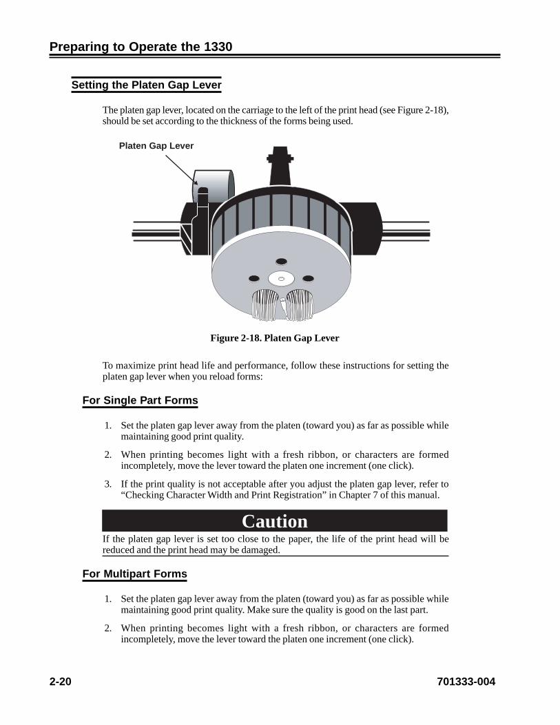
Setting the Platen Gap Lever
The platen gap lever, located on the carriage to the left of the print head (see Figure 2-18),should be set according to the thickness of the forms being used.
Platen Gap Lever
Figure 2-18. Platen Gap Lever
To maximize print head life and performance, follow these instructions for setting theplaten gap lever when you reload forms:
For Single Part Forms
1. Set the platen gap lever away from the platen (toward you) as far as possible whilemaintaining good print quality.
2. When printing becomes light with a fresh ribbon, or characters are formedincompletely, move the lever toward the platen one increment (one click).
3. If the print quality is not acceptable after you adjust the platen gap lever, refer to“Checking Character Width and Print Registration” in Chapter 7 of this manual.
CautionIf the platen gap lever is set too close to the paper, the life of the print head will bereduced and the print head may be damaged.
For Multipart Forms
1. Set the platen gap lever away from the platen (toward you) as far as possible whilemaintaining good print quality. Make sure the quality is good on the last part.
2. When printing becomes light with a fresh ribbon, or characters are formedincompletely, move the lever toward the platen one increment (one click).

701333-004 2-21
Preparing to Operate the 1330
3. If the print quality is not acceptable after you adjust the platen gap lever, refer to“Checking Character Width and Print Registration” in Chapter 7.
CautionIf the platen gap lever is set too close to the paper, the life of the print head will bereduced and the print head may be damaged. The platen gap lever must be far enoughfrom the platen to allow the shifter nosepiece to rotate smoothly, and to ensure that theforms are not smudged by the ribbon.
Installing the Forms Handler Module
This section explains how to install the Forms Handler module using the Document onDemand (DOD) option and the Document Insertion Device (DID) option.
Installing Forms Using the DOD Option
Refer to Figure 2-19 for a picture of the Forms Handler module set for the DOD option. Inthis procedure, you will first load paper into the module, then put the module into the 1330.
Paper Supports
Figure 2-19. Forms Handler Module (DOD Option)
1. Make sure the printer power is on, and the printer is in Stop mode. If necessary,press the Stop key.
2. For ease of handling, lay the module on the top of the printer.
3. Unlock the left forms tractor of the module.
4. Slide the left forms tractor to the right, as far as it will go.
5. Lock the left tractor.
6. Unlock the right forms tractor on the module.

2-22 701333-004
Preparing to Operate the 1330
7. Move the right tractor to the approximate width of the forms you plan to use. Note thatthree standard widths for computer pinfeed paper – 8 1/4 inches (21.0 cm), 9 1/2inches (24.1 cm), and 14 7/8 inches (37.8 cm) – are marked on the module.
8. Center the paper supports (Figure 2-19) an equal distance from the tractors andfrom each other. For narrow forms, you can snap out the paper supports.
9. Open the doors of both forms tractors.
10. Insert the paper into the front of the module, placing the paper on the tractor pins.Make sure that the paper does not extend beyond the pins.
11. Move the right tractor as necessary to get correct paper tension.
12. Close the tractor doors.
13. Lock the right forms tractor.
14. Insert the module into the front of the printer until it snaps firmly in place. Thedisplay window will show DOD.
15. Open the printer cover.
16. Move the platen gap lever toward you until it is completely open.
17. Close the printer cover.
18. Press the Load/Eject key to advance the forms to the top of form position.
19. Open the printer cover.
20. Adjust the setting of the platen gap lever, as necessary. Move the lever to a lowersetting (toward the platen) for darker print; move the lever to a higher setting (towardyou) for lighter print. If you are using multipart forms, make sure that the last copyis legible without any smudging on any other copy. If the last copy is too light, movethe lever to a lower setting. If the last copy is all right, but other copies are smudging,move the lever to a higher setting. Note that moving the lever will affect print headlife.
21. Unlock the 1330 right forms tractor.
22. Position the right tractor for the width of the forms. The arrow on the bottom of thetractor should point to the right edge of the forms.
Note: The edge of the forms should cover the roller in the tractor body, but should notengage the tractor pins.
23. Lock the right tractor.
24. Close the printer cover.
25. Press the Load/Eject key to advance the forms to the tear off position at the tear bar.If the forms are not in the correct position, adjust the position by using ConfigurationOption 411. Refer to Chapter 4 or Chapter 5 for instructions.
26. Press the Load/Eject key to move the forms back to the first print line.
Note: If your Forms Handler module is equipped with the roller drive option, moveboth of the white slide bars on the tractors to the left to disengage the roller

701333-004 2-23
Preparing to Operate the 1330
drive. The bars will snap into the OFF position, as shown in Figure 2-20.
Roller DriveShown OFF
Paper Supports
Slide Bar
Slide Bar
Figure 2-20. DOD Option with Roller Drive
Next is the procedure for using the Document Insertion Device (DID) option.
Installing Forms Using the DID Option
Refer to Figure 2-21 for a picture of the Forms Handler module set for the DID option. Inthis procedure, first set up the module for forms loading, next insert the module into theprinter, and finally load the forms into the printer.
Paper Supports
Figure 2-21. Forms Handler Module (DID Option)
1. Make sure the printer power is on, and the printer is in Stop mode.
2. For ease of handling, lay the module on top of the printer.

2-24 701333-004
Preparing to Operate the 1330
3. Unlock the left forms tractor of the module.
4. Slide the left forms tractor to the left, as far as it will go.
5. Lock the left tractor.
6. Unlock the right forms tractor on the module.
7. Insert a sample of the forms you plan to use into the module slot, making sure thatthe left edge of the forms is in contact with the left inside edge of the module.
8. Move the right tractor so that the arrow on the bottom of the tractor points to theright edge of the forms. Note that two standard widths for sheet feed paper – 8 1/4inches (21.0 cm) and 8 1/2 inches (21.6 cm) – are marked on the module.
9. Lock the right tractor.
10. Center the paper supports (Figure 2-22) an equal distance from the tractors andfrom each other. For narrow forms, snap out the paper supports.
11. Remove the sample forms.
12. Insert the module into the front of the printer. The display window will read DID.
13. Place the forms in the module (see (Figure 2-22) Use the left edge of the module tohelp feed the forms in straight. Insert the forms until the top edge contacts both theright and left feed rollers.
Figure 2-22. Inserting Paper - Forms Handler Module
14. While holding the forms lightly, press the Load/Eject key to move the forms to thetop of form position. Release the forms as the printer slowly advances them.
Note: If the forms are skewed, the printer will reject them, and the message 04 PAPERSKEW will be displayed. Go back to Step 13.

701333-004 2-25
Preparing to Operate the 1330
15. Open the printer cover.
16. Adjust the setting of the platen gap lever, as necessary. Move the lever to a lowersetting (toward the platen) for darker print; move the lever to a higher setting (towardyou) for lighter print. If you are using multipart forms, make sure that the last copyis legible without any smudging on any other copy. If the last copy is too light, movethe lever to a lower setting. If the last copy is all right, but other copies are smudging,move the lever to a higher setting. Note that moving the lever will affect print headlife.
17. Unlock the 1330 right forms tractor.
18. Position the right tractor for the width of the forms. The arrow on the bottom of thetractor should point to the right edge of the forms.
19. Lock the right tractor.
20. Close the printer cover.
21. Press the Start key to enable printing.
Note: If your Forms Handler module is equipped with the roller drive option, moveboth of the white slide bars on the tractors to the right to engage the DID rollerdrive. The bars will snap into position, and their right sides will extend beyondthe edges in the ON position, as shown in Figure 2-23.
Slide Bar
Paper Supports
Slide Bar
Roller DriveShown ON
Figure 2-23. DID Option with Roller Drive
The installation of the 1330 is now complete, and the printer is ready to print.
Before the 1330 can begin normal operations, it must be configured with the features andidentification information appropriate for your system. The configuration process isdiscussed in Chapter 4 and Chapter 5. Before you configure the 1330, you should befamiliar with the operator control panel and the display window messages, which areexplained in Chapter 3.

701333-004 3-1
Chapter 3. Operator Control Panel
The 1330 Operator Control Panel, located on the front of the printer, consists of thestatus display window and the keypad. The status display monitors printer operations,and the keypad is used to start and control operator functions. See Figure 3-1.
StartLoad/Eject
Top ofForm Option
ContrastSetup
StopForm Feed Line Space
SaveCancelPrint
Figure 3-1. 1330 Operator Control Panel
The Status Display
The 80-character status display window, located on the left side of the operator controlpanel, indicates the operating mode, the printing formats, and other conditions on the1330. Several of these messages are explained below. (See Figure 3-2 for status displaylayout.) Messages that appear during print format operations and configuration arediscussed in Chapters 4 and 5.
OPERATING MODECU S/C/A FORM DEVICE
EMULATIONMODE
DATASTREAMMODE
RESERVED LINE
STATUS MESSAGELINE
Figure 3-2. Status Display

3-2 701333-004
Operator Control Panel
Cu
In 3270 mode or share mode, the Cu signal displays when the 1330 is in communicationwith the controller. If the printer is receiving data, the Cu signal will blink.
S/C/A
The one-letter display indicates the current interface mode the printer is configured with.The valid displays for the interface option are “S” (share), “C” (3270), and “A” (ASCII).
Operating Mode
The 1330 has four types of operation modes: Start, Stop, Menu, and Contrast.
When the 1330 is in Start mode and ready to receive data, the READY message appearsin the status window.
When the printer is in Stop mode and awaiting an operator-initiated function, the STOPmessage appears in the status window. If the printer is left in Stop mode for more than 10minutes, either a status message is displayed in the window or the printer returns to Startmode, depending on how you have configured the printer.
When the operator is configuring the printer using the front panel option, the printer is inMenu mode. (See Chapter 4 for displays under the Menu mode.)
When the operator is adjusting the darkness of the print using the Contrast key, theprinter is in Contrast mode. (See Chapter 6 for displays under the Contrast mode.)
Please note that no printing takes place in Stop mode other than operator print. Datareceived from the controller will be printed only when the printer is in Ready mode.
Form Device
The form module installed with the printer will be displayed when the printer is configuredto sense the module. If you are using an overwrite feature in the configuration option, thedisplay will show the overwrite value. The form devices available for the 1330 are “CFD”(continuous forms device), “DOD” (document on demand), and “DID” (documentinsertion device).
Emulation Mode
The current printer emulation modes will be displayed in this location. The availableemulation modes for 3270 are “4230,” “4224,” “3268,” and “2124.” The availableemulation modes for ASCII are Proprinter and TI-810.

701333-004 3-3
Operator Control Panel
Datastream Mode/Interface Type
When host data is being processed, the type of datastream will be displayed in this location.The acceptable datastreams are LU1 (SCS), LU3 (DSC/DSE), LU1-IPDS, and LU3-IPDS. In ASCII, the interface type will be displayed. Those types can be parallel, RS-232, RS-422, or ASC.
Status Message
The 1330 displays the current printer status in this location. When the 1330 is operatedunder normal conditions, no message should be displayed. If an error is detected by theprinter, for example a paper jam, the printer will display PAPER JAM on the status line.If more than one error is detected at the same time, only the most serious one will bedisplayed on the status line. Once the problem is corrected, the status line will clear orthe next error message, if any, will be displayed.
The Keypad
The 1330 keypad, located on the right side of the operator control panel, works on apressure sensitive principle. When you press a key, a switch is activated that changes thestate or mode of the printer.
When you press an invalid keypad key, the printer will beep if the alarm is activated. Thealarm can be enabled or disabled during configuration. For instructions on how to configurethe alarm in 3270 mode, see Chapter 4, Configuration Options 402 and 403; for ASCIImode, see Chapter 5, Configuration Options 402 and 403.
Key Functions
The Start key puts the 1330 in Ready mode if the printer is not in Menu mode. If thesystem is sending data to be printed, and no error conditions appear in the display, thiskey starts the printer printing. This key also stops the printer alarm. If the 1330 is in Stopmode with the forms ejected in DOD mode, this key will not function until you put theform back to the normal condition by pressing the Load/Eject key. If the 1330 is in Menumode, the Start key will select the current option for configuration.
The Stop key puts the printer in Stop mode when the printer is in Ready or Menu mode.When running an operator test, the Stop key stops any test after the current line is finished.In Menu mode, the Stop key also serves as a return from an option to the menu list.
The Stop key also stops the printer alarm, and clears any displayed error conditions,provided they no longer exist. For example, in DOD mode, if the form is ejected and thecover is opened, the COVER OPEN message will display. Pressing the Stop key in Stopmode after the cover is closed will clear the previous COVER OPEN message and putthe original FORMS EJECTED message in the status window.
Start
Stop

3-4 701333-004
Operator Control Panel
With the Document Insertion Device, pressing the Load/Eject key at initial load willadvance the paper to the current position on the form. Pressing the key again will ejectthe paper.
With the Document on Demand device, pressing the Load/Eject key in Ready mode forinitial load will advance the paper to the first print line. Pressing the key a second timewill advance the paper to the tear line and put the printer in Stop mode so that you cantear the paper off using the tear bar. The status window will display the message FORMSEJECTED. Pressing the Load/Eject key a third time with the form ejected will clear thismessage from the display and will move the paper back to the current position on theform.
The Load/Eject key will work in both Start and Stop modes with the Forms Handlermodule. With the Continuous Forms Module, if the paper is out, you can press the Load/Eject key in Stop mode to eject the last sheet of paper.
The Form Feed key (which shares the key with Left Arrow) advances the forms so thatthe next form is positioned at the top of form. This function is used only with continuousforms and the Document on Demand option. Form feed is active only in Stop mode.
In Menu mode, the Left Arrow key scrolls through the available options or tests underthe current menu. After selecting an option, the Left Arrow key scrolls through the availablevalues of that option. The Left Arrow keys is also used to adjust the darkness of the printin Contrast mode.
The Up and Down Arrow keys, in Stop mode, move the forms 0.007 inch (0.18 mm) inthe direction of the arrow each time the key is pressed. If the Up Arrow key is held, theforms move continuously until the key is released. In Menu mode, the Up and DownArrow keys are used to scroll through the menu list. The Up Arrow moves forward throughthe menu, and the Down Arrow moves backward through the menu.
Note: If the Continuous Forms module is installed, do not use the Down Arrow keyfor continuous forms movement. The forms may become misaligned.
The Top of Form key sets the current position as the first print line on the forms. With theDocument Insertion Device installed and paper not loaded, this key will also cause thenext sheet loaded to begin printing at the first print line. This key is active only in Stopmode.
The Line Space key (which shares the key with Right Arrow) advances the forms upwardone line. If this key is held for more than 0.5 second, the forms will continue to moveforward until the key is released. The Line Space key is active only in Stop mode.
In Menu mode, the Right Arrow key scrolls through the available options or tests underthe current menu. After selecting an option, the Right Arrow key scrolls through theavailable values of that option. The Right Arrow key is also used to adjust the darkness ofthe print in Contrast mode.
Load/Eject
Form Feed
Top ofForm
Line Space

701333-004 3-5
Operator Control Panel
The Option key puts the 1330 in Menu mode. In Menu mode you can configure the 1330by setting options to the values you want or you can run diagnostic tests to verify theprinter’s performance. This key is active only in Stop mode.
The Save key is only active in Menu mode. It saves the value of the currently selectedoption when you are configuring the 1330 from the keypad. The Save key is also used tostart a test case under the Diagnostic menu.
The Contrast key in Ready mode enables the operator to get into the Contrast modewhere the operator can manually adjust the print for darkness. For more details, seeChapter 6.
The Setup key prints a setup line of Hs from the left margin to the right margin. TheSetup key is active in Stop mode and Contrast mode to help the operator verify thecurrent print format and print contrast.
The Cancel Print key cancels any chained SCS printing currently in process. This key isactive only in Stop mode.
Option
Save
ContrastSetup
CancelPrint

701333-004 4-1
Chapter 4. Configuring the 1330 in3270 Mode
The configuration process enables you to customize the 1330 to meet your specificoperating needs without assistance from Customer Service. You can also changeconfiguration parameters at any time without service costs.
The 1330 Operator Control Panel provides access to the configuration options. Now thatyou are familiar with the operator control panel, you are ready to configure the printer.Review the following summary of the configuration process before you begin.
Configuration Procedure
Using the Keys
Here are some general rules for keypad use in Menu mode:
• Press the Option key while in Stop mode to enter Menu mode.
• Press the Up Arrow key to scroll forward in the menu list.
• Press the Down Arrow key to scroll backward in the menu list.
• Press the Right Arrow to scroll forward in the options list under the current menu andto scroll forward in the value list under the currently selected option.
• Press the Left Arrow to scroll backward in the options list under the current menu andto scroll backward in the value list under the currently selected option.
• Press the Start key to select the current option.
• Press the Stop key to exit from a selected option or Menu mode.
• Press the Save key to activate a choice for the currently selected option.
Getting into the Menu Mode
You must get into the Menu mode when you want to configure the 1330. The procedurefor getting into the Menu mode is as follows:
1. Press the Stop key when the printer is in Ready mode.
2. Press the Option key to put the printer into the Menu mode. (If you do not have theoptional dual interface board installed in your printer, go to Step 4.)

4-2 701333-004
Configuring the 1330 in 3270 Mode
3. If the optional dual interface board is installed in your printer, the status display willgive you the option of pressing the Start key for the 3270 menu or pressing the Stopkey for the ASCII menu. At this point you may select one of the two menus to enteror press the Cancel key to quit and return the printer to the Ready mode.
4. You are now in the Menu mode. You will see the first menu of the menu list displayedon the first line of the status display and the first option of that menu displayed onthe second line of the status display. There may be some abbreviation of the menuname or its option in order to make it fit on the 20-character display.
Scrolling Through Menu Selections
You can find a specific option under a specific menu by using the arrow keys in thefollowing ways:
• Use the Up Arrow key to sequentially scroll forward through the menu list.
• Use the Down Arrow key to sequentially scroll backward through the menu list.
Every time an Up Arrow or Down Arrow key is pressed, you will see changes on the firstline of the status display. When the Main menu changes, the default option is automaticallychanged to list the first available option in the option list under the current menu.
• Use the Right Arrow key to sequentially scroll forward through the options list underthe current menu.
• Use the Left Arrow key to sequentially scroll backward through the options list underthe current menu.
Every time a Right Arrow or Left Arrow key is pressed, you will see changes on thesecond line of the status display. The first line of the status display will not change.
All of the arrow keys have a loopback feature that enables you to automatically start atthe top of a list once you have gotten to the end. See the tree chart on the following pagefor the choices in the menu list and all the options under each menu.
To run a test case, follow this procedure:
• Press the Save key to run the current test displayed under the Diagnostic menu on thedisplay. A POR will occur once you exit the Menu mode.
• Press the Stop key to stop a running test case.

701333-004 4-3
Configuring the 1330 in 3270 Mode
100
Pag
e F
orm
at
200
Fon
t & P
rint
Qua
lity
300
Com
patib
ility
400
Prin
ter
Set
up50
0C
omm
unic
atio
n60
0A
ttach
men
t
700
Ext
ende
dK
eypa
d
800
Pro
gram
Sym
bol
900
Vita
l Pro
duct
Dat
aD
iagn
ostic
Res
erve
d fo
rF
utur
e U
se
3270
Men
u
101
Left
Mar
gin
102
CP
I10
3 LP
I10
4 M
PP
105
For
m L
engt
h10
6 Li
ne S
paci
ng10
7 S
et M
edia
201
Lang
uage
202
Dis
play
Lan
guag
e20
3 M
ono/
Dua
l Cas
e20
4 B
old
Prin
t20
5 B
idir
2 P
ass
Prt
206
Prin
t Qua
lity
207
Hos
t Fas
t Dra
ft20
8 Te
st O
rient
atio
n20
9 D
otte
d Z
ero
210
Gra
phic
s D
ensi
ty
301
Car
riage
Ret
urn
at M
PP
+130
2 N
ew L
ine
at M
PP
+130
3 N
ull S
uppr
essi
on30
4 F
orm
Fee
d F
ollo
ws
305
For
m F
eed
with
Aut
o N
ew L
ine
at P
rint E
nd30
6 M
idlin
e F
orm
Fee
d30
7 F
orm
Fee
d P
rint w
ith a
Spa
ce30
8 F
orm
atte
d P
rint
309
Bar
Cod
e C
ontro
l31
0 B
ase
Col
or31
1 A
ttrib
ute
Hig
hlig
ht31
2 Ig
nore
SC
S C
omm
ands
401
Ope
rato
r F
orm
at40
2 K
ey A
larm
403
Ala
rm o
n E
rror
404
Prin
t Hea
d S
tyle
405
Prin
t Hea
d C
olum
n S
paci
ng40
6 R
ibbo
n Ty
pe O
verr
ide
407
Rib
bon
Trac
k S
elec
t Adj
ustm
ent
408
Mod
ule
Type
Ove
rrid
e40
9 A
utom
atic
For
m E
ject
410
Ful
l For
m F
eed
Eje
ct41
1 P
aper
Eje
ct A
djus
tmen
t41
2 H
oriz
onta
l Offs
et41
3 H
oriz
onta
l Reg
istr
atio
n41
4 P
aper
Jam
Sen
sor
Ena
ble
415
Pap
er O
ut S
enso
r E
nabl
e41
6 P
aper
Ske
w S
enso
r E
nabl
e41
8 D
OD
Loa
d A
djus
t41
9 D
ID L
oad
Adj
ust
420
Sto
p M
ode
Tim
eout
422
Sta
rt M
ode
Afte
r E
ject
423
Rep
ort I
nter
vent
ion50
1 P
rinte
r E
mul
atio
n M
ode
502
Buf
fer
Siz
e50
3 21
24 E
scap
e C
hara
cter
504
Ear
ly P
rint C
ompl
ete
601
Inte
rfac
e60
2 Id
le T
imeo
ut
701
Prin
t Con
figur
atio
n70
2 Q
uick
Ref
eren
ce70
3 S
et F
acto
ry D
efau
lt70
4 P
OR
Cus
tom
Set
705
Sav
e C
ust S
et70
6 R
ecal
l Cus
t Set
707
Dis
play
Cha
ract
er C
ount
708
PA1
709
PA2
710
Buf
fer
Rep
rint
801
Pro
gram
med
Sym
bols
802
Res
erve
d fo
r fu
ture
use
803
Res
erve
d fo
r fu
ture
use
804
APA
Prin
t Dire
ctio
n
901
Ser
ial N
umbe
r90
2 D
evic
e S
peci
ficat
ion
Info
rmat
ion

4-4 701333-004
Configuring the 1330 in 3270 Mode
Selecting a Menu Option
When the target menu appears on the first line of the status display, you can get into thatoption and configure the printer by changing the value of that option. Follow these steps:
1. To select an option, press the Start key when the option you want to change appearson the second line of the status display. Once an option is selected, the originallysaved value of that option will appear on the third line of the status display.
2. Press the Left Arrow and Right Arrow keys to move through the list of availablevalues for that option.
3. If you want to change the value of the selected option, press the Save key while thedesired value appears on the status display. (An asterisk at the beginning of the thirdline of the display indicates the currently saved value for the selected option.)
4. Press the Stop key to exit the selected option.
Note: You will not be able to move to the next option or to another menu until youhave exited the currently selected option.
Leaving Menu Mode
You can exit the Menu mode by pressing the Stop key until the READY message isdisplayed.
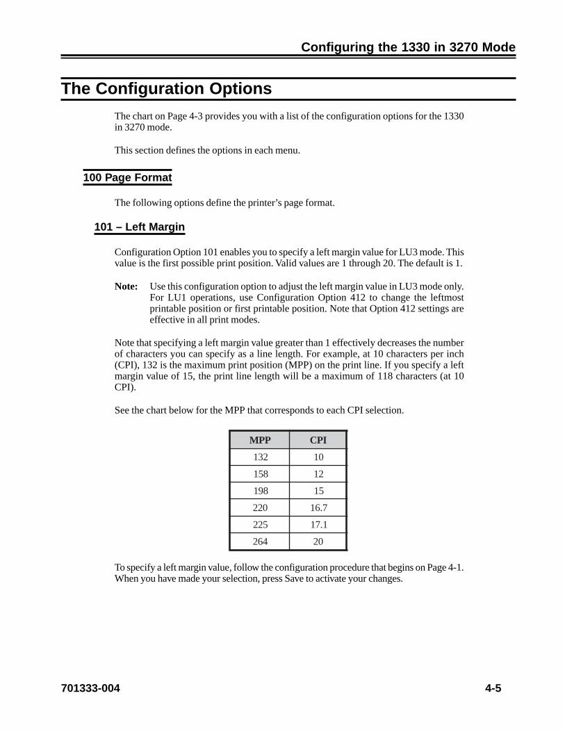
701333-004 4-5
Configuring the 1330 in 3270 Mode
The Configuration Options
The chart on Page 4-3 provides you with a list of the configuration options for the 1330in 3270 mode.
This section defines the options in each menu.
100 Page Format
The following options define the printer’s page format.
101 – Left Margin
Configuration Option 101 enables you to specify a left margin value for LU3 mode. Thisvalue is the first possible print position. Valid values are 1 through 20. The default is 1.
Note: Use this configuration option to adjust the left margin value in LU3 mode only.For LU1 operations, use Configuration Option 412 to change the leftmostprintable position or first printable position. Note that Option 412 settings areeffective in all print modes.
Note that specifying a left margin value greater than 1 effectively decreases the numberof characters you can specify as a line length. For example, at 10 characters per inch(CPI), 132 is the maximum print position (MPP) on the print line. If you specify a leftmargin value of 15, the print line length will be a maximum of 118 characters (at 10CPI).
See the chart below for the MPP that corresponds to each CPI selection.
PPM IPC
231 01
851 21
891 51
022 7.61
522 1.71
462 02
To specify a left margin value, follow the configuration procedure that begins on Page 4-1.When you have made your selection, press Save to activate your changes.
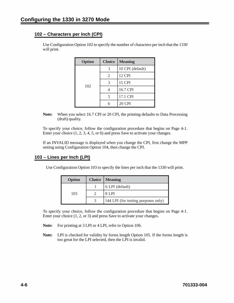
4-6 701333-004
Configuring the 1330 in 3270 Mode
102 – Characters per Inch (CPI)
Use Configuration Option 102 to specify the number of characters per inch that the 1330will print.
noitpO eciohC gninaeM
201
1 )tluafed(IPC01
2 IPC21
3 IPC51
4 IPC7.61
5 IPC1.71
6 IPC02
Note: When you select 16.7 CPI or 20 CPI, the printing defaults to Data Processing(draft) quality.
To specify your choice, follow the configuration procedure that begins on Page 4-1.Enter your choice (1, 2, 3, 4, 5, or 6) and press Save to activate your changes.
If an INVALID message is displayed when you change the CPI, first change the MPPsetting using Configuration Option 104, then change the CPI.
103 – Lines per Inch (LPI)
Use Configuration Option 103 to specify the lines per inch that the 1330 will print.
noitpO eciohC gninaeM
301
1 )tluafed(IPL6
2 IPL8
3 )ylnosesoprupgnitsetrof(IPL441
To specify your choice, follow the configuration procedure that begins on Page 4-1.Enter your choice (1, 2, or 3) and press Save to activate your changes.
Note: For printing at 3 LPI or 4 LPI, refer to Option 106.
Note: LPI is checked for validity by forms length Option 105. If the forms length istoo great for the LPI selected, then the LPI is invalid.
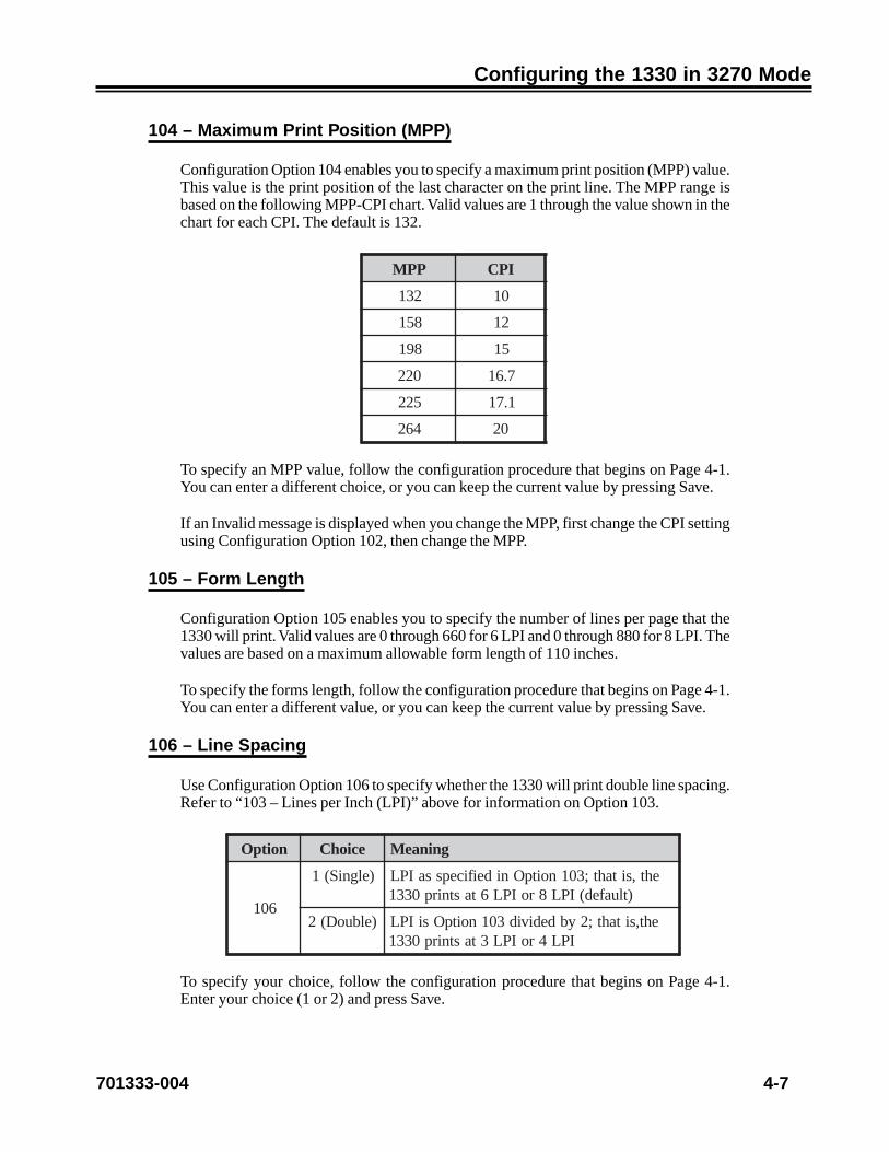
701333-004 4-7
Configuring the 1330 in 3270 Mode
104 – Maximum Print Position (MPP)
Configuration Option 104 enables you to specify a maximum print position (MPP) value.This value is the print position of the last character on the print line. The MPP range isbased on the following MPP-CPI chart. Valid values are 1 through the value shown in thechart for each CPI. The default is 132.
PPM IPC
231 01
851 21
891 51
022 7.61
522 1.71
462 02
To specify an MPP value, follow the configuration procedure that begins on Page 4-1.You can enter a different choice, or you can keep the current value by pressing Save.
If an Invalid message is displayed when you change the MPP, first change the CPI settingusing Configuration Option 102, then change the MPP.
105 – Form Length
Configuration Option 105 enables you to specify the number of lines per page that the1330 will print. Valid values are 0 through 660 for 6 LPI and 0 through 880 for 8 LPI. Thevalues are based on a maximum allowable form length of 110 inches.
To specify the forms length, follow the configuration procedure that begins on Page 4-1.You can enter a different value, or you can keep the current value by pressing Save.
106 – Line Spacing
Use Configuration Option 106 to specify whether the 1330 will print double line spacing.Refer to “103 – Lines per Inch (LPI)” above for information on Option 103.
noitpO eciohC gninaeM
601
)elgniS(1 eht,sitaht;301noitpOnideificepssaIPL)tluafed(IPL8roIPL6tastnirp0331
)elbuoD(2 eht,sitaht;2ybdedivid301noitpOsiIPLIPL4roIPL3tastnirp0331
To specify your choice, follow the configuration procedure that begins on Page 4-1.Enter your choice (1 or 2) and press Save.

4-8 701333-004
Configuring the 1330 in 3270 Mode
107 – Force Set Media Size
With Configuration Option 107, in IPDS mode, you can choose to unconditionally honorthe Set Media Size command. If you choose 0 (disable), the page size will be the smallerof the operator panel settings and the Set Media Size values.
noitpO eciohC gninaeM
31)elbasiD(0
rotareponehwylnoeziSaideMteSronoH)tluafed(retaergerasgnitteslenap
)elbanE(1 yllanoitidnocnueziSaideMteSronoH
To specify your choice, follow the configuration procedure that begins on Page 4-1.Enter your choice (0 or 1) and press Save.
200 Font & Print Quality
The following options define the printer’s font and print quality.
201 – Language
Configuration Option 201 enables you to select the language character set for the 1330.Note that the selected language character set does not become active until after the newconfiguration values have been saved and the configuration sequence ended.
noitpO eciohC gninaeM
102
1 )tluafed(hsilgnESU2 namreG/nairtsuA3 etanretlAnamreG/nairtsuA4 naigewroN/hsinaD5 etanretlAnaigewroN/hsinaD6 hsidewS/hsinniF7 etanretlAhsidewS/hsinniF8 hcnerF9 nailatI01 etanretlAeseugutroP11 hsinapS21 etanretlAhsinapS31 KUhsilgnE41 naigleB51 nailizarB61 hsilgnEesenapaJ71 gnikaepShsinapS

701333-004 4-9
Configuring the 1330 in 3270 Mode
noitpO eciohC gninaeM
102
81 5teSlanoitanretnI91 1teSlanoitanretnI02 anakataKesenapaJ12 eseugutroP22 laugniliBssiwS32 501ytrezAhcnerF42 hcnerFnaidanaC52 laugniliBnaidanaC62 cibarA72 )elbitapmoc-4224MBI(TLBwerbeH82 weNwerbeH92 dlOwerbeH03 iahT13 hsikruT23 A-RCO33 B-RCO43 cidnalecI53 ECEOR/nitaL63 cilliryC73 keerGweN83 keerGdlO93 valsoguY04 gniwarDeniL
To select a language character set, follow the configuration procedure that begins onPage 4-1. You can select another language character set by entering its correspondingnumber, or you can keep the current selection by pressing Save.
202 – Display Language
Use Configuration Option 202 to select a specific country language to display messages.The languages available for the option are English (default), French, and German. Somedomestic units support only English.
To select a language character set, follow the configuration procedure that begins onPage 4-1.

4-10 701333-004
Configuring the 1330 in 3270 Mode
203 – Mono/Dual Case
Configuration Option 203 enables you to specify whether the 1330 will print in monocase (all characters uppercase) or dual case (characters uppercase and lowercase) in LU3mode.
noitpO eciohC gninaeM
302
1 esacreppunidetnirperasretcarahclla–esaconoM
2 esacreppunitnessadetnirperasretcarahc–esaclauD)tluafed(esacrewoldna
To specify your choice, follow the configuration procedure that begins on Page 4-1.Enter your choice (1 or 2) and press Save.
204 – Bold Print Enable
Use Configuration Option 204 to enable or disable bold print. If you specify YES (byentering 1), bold print will be enabled.
noitpO eciohC gninaeM
402)oN(0 )tluafed(delbasidsitnirpdloB
)seY(1 delbanesitnirpdloB
To specify your choice, follow the configuration procedure that begins on Page 4-1.Enter your choice (0 or 1) and press Save.
205 – Two-Pass Print Direction
Use Configuration Option 205 to better align the two print head passes on printing thatrequires two passes. This option could be useful during subtractive color printing.
With Choice 1, the print head will make two unidirectional passes. With Choice 2, theprint head will make one bidirectional pass. Choice 1 will give you truer, crisper colorson the printout; however, throughput will be reduced, and Choice 2 will give fasteroperation.
noitpO eciohC gninaeM
5021 sessaplanoitceridinuowtsekamdaehtnirpehT
2 )tluafed(ssaplanoitceridibenosekamdaehtnirpehT
To specify your choice, follow the configuration procedure that begins on Page 4-1.Enter your choice (1 or 2) and press Save.
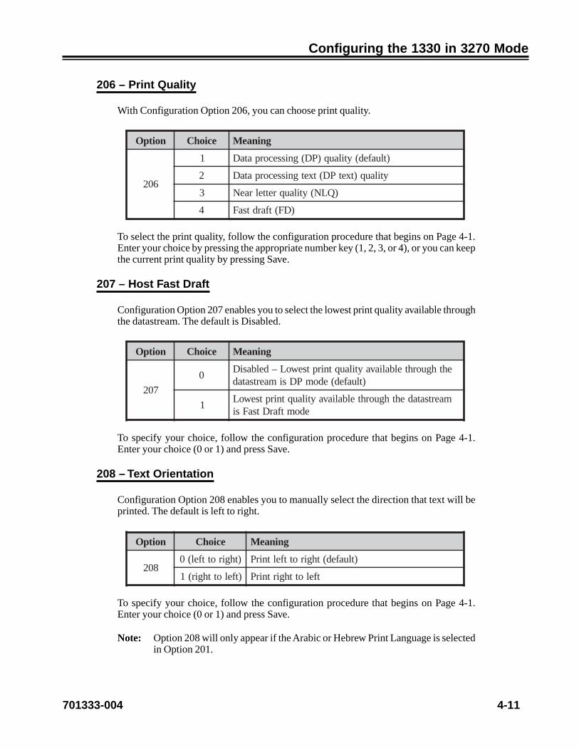
701333-004 4-11
Configuring the 1330 in 3270 Mode
206 – Print Quality
With Configuration Option 206, you can choose print quality.
noitpO eciohC gninaeM
602
1 )tluafed(ytilauq)PD(gnissecorpataD
2 ytilauq)txetPD(txetgnissecorpataD
3 )QLN(ytilauqrettelraeN
4 )DF(tfardtsaF
To select the print quality, follow the configuration procedure that begins on Page 4-1.Enter your choice by pressing the appropriate number key (1, 2, 3, or 4), or you can keepthe current print quality by pressing Save.
207 – Host Fast Draft
Configuration Option 207 enables you to select the lowest print quality available throughthe datastream. The default is Disabled.
noitpO eciohC gninaeM
702
0ehthguorhtelbaliavaytilauqtnirptsewoL–delbasiD
)tluafed(edomPDsimaertsatad
1maertsatadehthguorhtelbaliavaytilauqtnirptsewoL
edomtfarDtsaFsi
To specify your choice, follow the configuration procedure that begins on Page 4-1.Enter your choice (0 or 1) and press Save.
208 – Text Orientation
Configuration Option 208 enables you to manually select the direction that text will beprinted. The default is left to right.
noitpO eciohC gninaeM
802)thgirottfel(0 )tluafed(thgirottfeltnirP
)tfelotthgir(1 tfelotthgirtnirP
To specify your choice, follow the configuration procedure that begins on Page 4-1.Enter your choice (0 or 1) and press Save.
Note: Option 208 will only appear if the Arabic or Hebrew Print Language is selectedin Option 201.

4-12 701333-004
Configuring the 1330 in 3270 Mode
209 – Dotted Zero
Use Configuration Option 209 to specify whether a dotted zero should be printed whena zero is selected. If you specify NO, the dotted zero will not be used.
noitpO eciohC gninaeM
902)oN(0 )tluafed(desuebtonlliworezdettodehT
)seY(1 desueblliworezdettodehT
To specify your choice, follow the configuration procedure that begins on Page 4-1.Enter your choice (0 or 1) and press Save.
Note: When you request OCR-A, OCR-B, APL, or printing any fonts in diagnostics,the printer will use the undotted zero, regardless of the operator panel selection.
210 – Graphics Density
Use Configuration Option 210 to specify the Graphics Density mode. Low density graphicsenables printing to switch from 144 (high) to 72 (low) dots per inch, thus moving theprint head at a faster rate.
noitpO eciohC gninaeM
012
0 scihpargytisnedwol/edocrabtsartnocwoL
1 )tluafed(scihpargytisnedhgih/edocrabtsartnochgiH
2 scihpargytisnedwol/edocrabtsartnochgiH
3 scihpargytisnedhgih/edocrabtsartnocwoL
4 maertsatadnideificepsytisned–edomdetcelestsoH
To specify your choice, follow the configuration procedure that begins on Page 4-1.Enter your choice (0, 1, 2, 3, or 4) and press Save.
Note: This option is valid only in IPDS mode. Your choice will override any valuefrom the application program (unless you select Value 4).

701333-004 4-13
Configuring the 1330 in 3270 Mode
300 Compatibility
The following options define the printer’s compatibility.
301 – Carriage Return (CR) at MPP + 1
Configuration Option 301 allows you to choose whether the printer will do a carriagereturn (CR) after the maximum print position (MPP) of a print line has been exceeded.
noitpO eciohC gninaeM
103
)oN(0no1noitisopotdaehtnirpehtsevom1+PPMtaRC
rucconacgnitnirprevotahtos,enilemaseht
)seY(1no1noitisopotdaehtnirpehtsevom1+PPMtaRC
)tluafed(eniltxeneht
To specify your choice, follow the configuration procedure that begins on Page 4-1.Enter your choice (0 or 1) and press Save.
302 – New Line (NL) at MPP + 1
Use Configuration Option 302 to specify whether the print head will move one new line(NL) or two new lines after the maximum print position (MPP) of a print line has beenexceeded.
noitpO eciohC gninaeM
203
)oN(0no1noitisopotdaehtnirpehtsevom1+PPMtaLN
eniltxeneht
)seY(1no1noitisopotdaehtnirpehtsevom1+PPMtaLN
)tluafed(eniltxenehtretfaenileht
To specify your choice, follow the configuration procedure that begins on Page 4-1.Enter your choice (0 or 1) and press Save.
303 – Null Suppression
Use Configuration Option 303 to specify how the printer will handle null characters.This option is valid for LU3 mode only.
noitpO eciohC gninaeM
303
)oN(0 sllunfoenileritnerofdeefenilseoD
)seY(1foenileritnerofdegnahcnusniamernoitisoptnirP
)tluafed(sllun
To specify your choice, follow the configuration procedure that begins on Page 4-1.Enter your choice (0 or 1) and press Save.

4-14 701333-004
Configuring the 1330 in 3270 Mode
304 – Form Feed (FF)
Use Configuration Option 304 to specify if the 1330 will perform a form feed (FF)operation before or after a local print, after an LU3 print, or never.
noitpO eciohC gninaeM
403
1)tnirp3ULotdeddaFFoN(tnirpswollofFFoN
)tluafed(
2 tnirplacolretfaFF
3 tnirp3ULretfaFF
4 tnirplacolerofebFF
5 tnirplacolretfadnaerofebFF
To specify your choice, follow the configuration procedure that begins on Page 4-1.Enter your choice (1, 2, 3, 4, or 5) and press Save.
305 – Form Feed with Auto New Line at Print End
Use Configuration Option 305 to specify whether, after a print, the 1330 will move theprint head to the first line or second line of the next page.
noitpO eciohC gninaeM
503
)oN(0 1retcarahc,1enilmroffopototdaehtnirpehtsevoM
)seY(11retcarahc,2enilmroffopototdaehtnirpehtsevoM
)tluafed(
To specify your choice, follow the configuration procedure that begins on Page 4-1.Enter your choice (0 or 1) and press Save.
306 – Midline Form Feed (FF)
Configuration Option 306 is used to specify whether to use the midline form feed (FF)feature, which allows the form feed character to be placed in any position on a print line.
noitpO eciohC gninaeM
603)oN(0 )tluafed(1noitisoptaylnoFF
)seY(1 PPMot1morfnoitisopynataFF
To specify your choice, follow the configuration procedure that begins on Page 4-1.Enter your choice (0 or 1) and press Save.

701333-004 4-15
Configuring the 1330 in 3270 Mode
307 – Form Feed (FF) Printed with a Space
Use Configuration Option 307 to specify whether the print head will move to the firstcharacter position or second character position on the next top of form (TOF).
noitpO eciohC gninaeM
703)oN(0 1retcarahc,FOTtadaehtnirpehtstuP
)seY(1 )tluafed(2retcarahc,FOTtadaehtnirpehtstuP
To specify your choice, follow the configuration procedure that begins on Page 4-1.Enter your choice (0 or 1) and press Save.
308 – Formatted Print
Configuration Option 308 allows you to select the formatted print override, a feature thathonors certain format commands in spite of a formatted print request from the host CPU.Carriage Return, End of Message, and New Line commands are active, and null lines arenot suppressed. The host CPU defined line length is honored. To activate the formattedprint override feature, select 1.
noitpO eciohC gninaeM
803
)oN(0 egasseMfodnEdna,nruteRegairraC,eniLweN)tluafed(detnirpsiecapsa–derongiera
)seY(1 egasseMfodnEdna,nruteRegairraC,eniLweNdetucexeera
To specify your choice, follow the configuration procedure that begins on Page 4-1.Enter your choice (0 or 1) and press Save.
309 – Bar Code Control
Use Configuration Option 309 to configure the bar code printout in 2124 emulationmode.
noitpO eciohC gninaeM
903
1 tnofedocrab4212dradnatsehtsesU–dradnatS)tluafed(retnirpehtni
2 rellamsaottnofsesserpmoC–tnoFdesserpmoC.elbaliavasi9fo3edocrabylnoyltnerruC.ezis
tonsitnofdesserpmocedocrabtnerrucehtnehW.ezisdradnatsottluafed,elbaliava
3 ehtotresolcebotpuIRHsevoM–IRHresolClliwIRH,eulavsihtotderugifnocnehW.edocrab
fi,tnofdesserpmocehtesuyllacitamotua.tnofdradnatssesu,elbaliavatonfI.elbaliava

4-16 701333-004
Configuring the 1330 in 3270 Mode
This option shall not have any effect in IPDS bar code printing.
To specify the bar code control default, follow the configuration procedure that beginson Page 4-1. Enter your choice (1, 2, or 3) and press Save.
310 – Base Color
Use Configuration Option 310 to specify whether the base color of the printed text defaultsto green or black when you power on the printer. The controller can override the operatorfield attribute enable/disable setting.
noitpO eciohC gninaeM
013
1 delbaneerasetubirttadleifdnakcalbsirolocesaB)tluafed(
2 delbasiderasetubirttadleifdnakcalbsirolocesaB
3 delbaneerasetubirttadleifdnaneergsirolocesaB
4 delbasiderasetubirttadleifdnaneergsirolocesaB
To specify the base color default, follow the configuration procedure that begins on Page4-1. Enter your choice (1, 2, 3, or 4) and press Save.
311 – Attribute Selectable Highlighting
Use Configuration Option 311 to choose attribute selectable normal operation, bolding,or underscore.
In LU1, when bolding is selected, the attributes that normally control underscore willcontrol bold instead. Underscore will never be changed. This includes resetting attributesat first in chain or only in chain: bold will be reset and underscore will not be changed.
In LU1, when underscore is selected, operation is identical to normal operation.
In LU3 with a color ribbon, when bolding is selected, character attributes and extendedfield attributes normally controlling underscore will control bold instead. Underscorewill never be changed.
In LU3 with a color ribbon, when underscore is selected, operation is identical to normaloperation.
In LU3 with a monochrome ribbon, operation is identical to that of LU3 with a colorribbon, with this addition: when bold or underscore is selected, the field attributes willcontrol bolding or underscore.
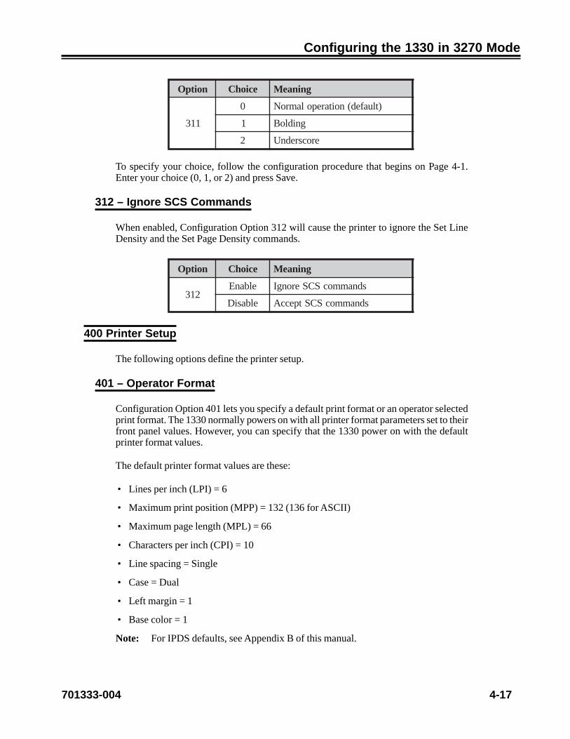
701333-004 4-17
Configuring the 1330 in 3270 Mode
noitpO eciohC gninaeM
113
0 )tluafed(noitarepolamroN
1 gnidloB
2 erocsrednU
To specify your choice, follow the configuration procedure that begins on Page 4-1.Enter your choice (0, 1, or 2) and press Save.
312 – Ignore SCS Commands
When enabled, Configuration Option 312 will cause the printer to ignore the Set LineDensity and the Set Page Density commands.
noitpO eciohC gninaeM
213elbanE sdnammocSCSerongI
elbasiD sdnammocSCStpeccA
400 Printer Setup
The following options define the printer setup.
401 – Operator Format
Configuration Option 401 lets you specify a default print format or an operator selectedprint format. The 1330 normally powers on with all printer format parameters set to theirfront panel values. However, you can specify that the 1330 power on with the defaultprinter format values.
The default printer format values are these:
• Lines per inch (LPI) = 6
• Maximum print position (MPP) = 132 (136 for ASCII)
• Maximum page length (MPL) = 66
• Characters per inch (CPI) = 10
• Line spacing = Single
• Case = Dual
• Left margin = 1
• Base color = 1
Note: For IPDS defaults, see Appendix B of this manual.

4-18 701333-004
Configuring the 1330 in 3270 Mode
If you choose an operator selected print format for Option 401, the last value saved foreach parameter becomes the new default value when the printer is powered on.
noitpO eciohC gninaeM
1041 tamroftluafeD
2 )tluafed(tamrofdetcelesrotarepO
To specify your choice, follow the configuration procedure that begins on Page 4-1.Enter the your choice (1 or 2) and press Save.
402 – Key Alarm
Use Configuration Option 402 to specify whether a beep will sound each time a key onthe touchpad is pressed. If you specify NO (by entering 0), the touchpad will not produceaudible feedback.
noitpO eciohC gninaeM
204)oN(0 )tluafed(desserpsiyekanehwdnuostonseodmralaehT
)seY(1 desserpsiyekanehwsdnuosmralaehT
To specify your choice, follow the configuration procedure that begins on Page 4-1.Enter your choice (0 or 1) and press Save.
403 – Alarm on Error
Use Configuration Option 403 to specify whether an alarm will sound when an erroroccurs. If you specify NO (by entering 0), the alarm will not sound.
noitpO eciohC gninaeM
304
)oN(0 sruccororrenanehwdnuostonseodmralaehT
)seY(1 llatonhguoht(sruccororrenanehwsdnuosmralaehT)tluafed()mralaehtdnuoslliwsrorre
To specify your choice, follow the configuration procedure that begins on Page 4-1.Enter your choice (0 or 1) and press Save.
404 – Print Head Style
When you change the print head, you must inform the 1330 which print head style iscurrently installed by using this configuration option.
CautionFailure to enter the correct print head style under Option 413 can result in poor print headperformance and damage to the print head.

701333-004 4-19
Configuring the 1330 in 3270 Mode
Before specifying the print head style, turn the printer off. Refer to the label on the printhead to determine which style of print head is installed. If you are installing a new printhead, see “Replacing the Print Head” in Chapter 7 of this manual for instructions.
After you have determined the style of print head currently in use, turn the 1330 back on.
To inform the printer of the print head style, follow the configuration procedure thatbegins on Page 4-1. Use the chart below to determine your print head style.
noitpO eciohC gninaeM
4041 )tluafed(dellatsnisi1elytsdaehtnirP
2 dellatsnisi2elytsdaehtnirP
If the correct print head style number is displayed, press Save. If the number does notcorrespond to the print head style, enter the correct number (1 or 2) and press Save.
405 – Print Head Column Spacing
Configuration Option 405 enables you to correct for spacing variations between the banksof print wires on the print head. If the dots in a vertical column of a character symbolappear to be misaligned, Option 405 can be used to correct this condition. Valid valuesrange from 90 to 100. The default is 95. Refer to “Checking Character Width” in Chapter7 for complete instructions.
••••••••
••••••••tcerroC tcerrocnI
Figure 4-1. Aligned and Unaligned Dots in Characters
406 – Ribbon Type Override
Configuration Option 406 enables you to override the type of ribbon installed in theprinter.

4-20 701333-004
Configuring the 1330 in 3270 Mode
noitpO eciohC gninaeM
604
0 )tluafed(edirrevoon–rosnesepytnobbiresU
1 nobbir)roloc-4(tnecca–epytnobbiredirrevO
2 nobbir)roloc-8(evitcartbus–epytnobbiredirrevO
3 nobbiremorhconom–epytnobbiredirrevO
In normal operation, the default should be used. The other choices enable the printer tobe used with a faulty ribbon or ribbon sensor. The other choices are not recommendedunless the ribbon or sensor is faulty.
To specify your choice, follow the configuration procedure that begins on Page 4-1.Enter your choice (0, 1, 2, or 3) and press Save.
407 – Ribbon Track Select Adjustment
Configuration Option 407 enables you to adjust the home position of the ribbon trackselect mechanism. If the printout is showing a color mix, Option 407 can be used tocorrect this condition. Valid values are 0 through 10. The default is 5.
To adjust the home position, follow the configuration procedure that begins on Page 4-1.407 TRAK SEL ADJ will display in the status window, followed by the current value. Ifthe printout has a color mix at the top of the characters, enter a lesser value. If the printoutshows a color mix at the bottom of the characters, enter a greater value. You can keep thecurrent value by pressing Save.
408 – Module Type Override
Configuration Option 408 enables you to override the type of forms module installed inthe printer. You can enter 0 to disable the override and use the module sensor. Or you canchoose to override the Document Insertion Device (DID) option, the Document onDemand (DOD) option, or the Continuous Forms module.
noitpO eciohC gninaeM
804
0 )tluafed(edirrevoon–rosneseludomesU
1 eludomsmroFsuounitnoCehtedirrevO
2 noitpoDODehtedirrevO
3 noitpoDIDehtedirrevO
In normal operation, the default should be used. The other choices enable the printer tobe used with a faulty module or sensor. The other choices are not recommended unlessthe module or sensor is faulty.
To specify your choice, follow the configuration procedure that begins on Page 4-1.Enter your choice (0, 1, 2, or 3) and press Save.

701333-004 4-21
Configuring the 1330 in 3270 Mode
409 – Auto Eject
To make it easy for you to tear off forms, configuration Option 409 enables you to havean automatic form eject after the 1330 has been idle in DOD mode for an operatorselectable time period. After additional data is received, the form will be retracted. If youchoose 0 (Disabled), the auto eject will not function.
noitpO eciohC gninaeM
904)delbasiD(0 )tluafed(atadfodneehttaruccotonlliwtcejemroF
)sdnoceS(552-1 ytpmesireffubehtretfasdnocesnruccolliwtcejemroF
To specify your choice, follow the configuration procedure that begins on Page 4-1.Enter your choice (0 or 1-255) and press Save.
410 – Full Form Feed Eject
Configuration Option 410 is used to specify whether to use the full form feed eject feature,which ejects the form from the print head to the tear point in DOD mode.
noitpO eciohC gninaeM
014
)oN(0 )tluafed(tcejelamroN
)seY(1 sitcejeDODa,desserpsiyektcejE/daoLehtnehWmrofehtfodneehtlitnudeyaled
To specify your choice, follow the configuration procedure that begins on Page 4-1.Enter your choice (0 or 1) and press Save.
Note: You can select 1 in any mode. However, if the printer is not in DOD mode, thealarm will sound to alert you that the selection will not be effective until theprinter is put in DOD mode.
411 – Paper Eject Adjustment
To align the forms for easy tear off, configuration Option 411 is used in conjunction withthe DOD Forms Handler module. This option enables you to adjust the distance thepaper moves when you press the Load/Eject key while the DOD option is installed. Validvalues are 0 through 255. The default is 127.
To adjust the paper eject distance, follow the configuration procedure that begins onPage 4-1. EJECT ADJUST will display in the status window, followed by the currentvalue. If you enter a greater value, the paper will eject higher. If you enter a lesser value,the paper will eject lower. You can keep the current value by pressing Save.

4-22 701333-004
Configuring the 1330 in 3270 Mode
412 – Horizontal Offset
Use Configuration Option 412 to set the first printable position on the page. Values rangebetween 0 and 127. Units are in increments of 0.007 inch (0.02 cm), so the offset isbetween 0 and 0.88 inch (0 to 2.24 cm). The default is 14.
To specify your choice, follow the configuration procedure that begins on Page 4-1.Enter your choice (from 0 to 127) and press Save.
Note: If you go to this feature frequently, you may want to use a shortcut to its options.Follow this procedure: In Ready mode press the Option key. That will take youto Express 412, where you can use the arrow keys to select the values as younormally would. Once you have chosen the values you want, press the Start keyand your setup will be saved.
413 – Horizontal Registration
Configuration Option 413 enables you to adjust the printed line horizontally for verticalcharacter alignment. Values range between 0 and 255. The default is 127. Units are inincrements of 0.0007 inch (0.002 cm). Note that this option is used with bidirectionalprinting only. For complete instructions, refer to “Checking Print Registration” in Chapter 7.
414 – Paper Jam Sensor Enable
Use Configuration Option 414 to enable or disable the paper jam sensor. If you specifyNO (by entering 0), the paper jam sensor will be disabled.
noitpO eciohC gninaeM
414)oN(0 delbasidsirosnesmajrepapehT
)seY(1 )tluafed(delbanesirosnesmajrepapehT
To specify your choice, follow the configuration procedure that begins on Page 4-1.Enter your choice (0 or 1) and press Save.
415 – Paper Out Sensor Enable
Configuration Option 415 enables and disables the paper out sensor. If the paper outsensor is disabled, the alarm is prevented from sounding when the printer is out of paper.
CautionWhen the paper out sensor is disabled, the printer will not be able to detect a paper outcondition. If the printer continues printing without paper for an extended period, theprint head could be damaged.

701333-004 4-23
Configuring the 1330 in 3270 Mode
noitpO eciohC gninaeM
514)oN(0 delbasidsirosnestuorepapehT
)seY(1 )tluafed(delbanesirosnestuorepapehT
To specify your choice, follow the configuration procedure that begins on Page 4-1.Enter your choice (0 or 1) and press Save.
416 – Paper Skew Sensor Enable
Use Configuration Option 416 to enable or disable the paper skew sensor. If you specifyNO (by entering 0), the paper skew sensor will be disabled.
noitpO eciohC gninaeM
614)oN(0 delbasidsirosnesweksrepapehT
)seY(1 )tluafed(delbanesirosnesweksrepapehT
To specify your choice, follow the configuration procedure that begins on Page 4-1.Enter your choice (0 or 1) and press Save.
418 – DOD Load Adjust
Use Configuration Option 418 to set the distance between the top of the form and thebottom of the characters in the first print line. Values range from 20 to 255, in .007-inchincrements.
For example, if you have a box you want to print in as the first print line, measure thedistance from the physical top of the form to the line you want to print on. Convert thedistance to .007 inches and enter the distance as the value for the Load Adjust parameter.
Note that you will only be able to access the option that corresponds to the device youhave in the printer; that is, if you have a DOD device, the menu will only allow you toaccess the DOD Load Adjust option.
Loads can be initiated in Stop or Ready mode with a DID device, but only in Readymode with a DOD device.
419 – DID Load Adjust
Use Configuration Option 419 to set the distance between the top of the form and thebottom of the characters in the first print line. Values range from 20 to 255, in .007-inchincrements.
For example, if you have a box you want to print in as the first print line, measure thedistance from the physical top of the form to the line you want to print on. Convert thedistance to .007 inches and enter the distance as the value for the Load Adjust parameter.

4-24 701333-004
Configuring the 1330 in 3270 Mode
Note that you will only be able to access the option that corresponds to the device youhave in the printer; that is, if you have a DID device, the menu will only allow you toaccess the DID Load Adjust option.
Loads can be initiated in Stop or Ready mode with a DID device, but only in Readymode with a DOD device.
420 – Stop Mode Timeout (TO)
Configuration Option 420 enables you to select what the 1330 will do when it has beenin Stop mode for more than 10 minutes. You can specify whether the printer will continuein Stop mode, or whether it will go to Start mode.
noitpO eciohC gninaeM
024
1
ti,setunim01nahteromrofedompotSnitfelsi0331ehtfIedomtratSotnruterlliw
smrofehthtiwedompotSnitfelsi0331ehtfi,edomDODnIyllacitamotualliw0331eht,setunim01nahteromrofdetceje
edomtratSotnruterdnasmrofehttcarter
2na,setunim01nahteromrofedompotSnitfelsi0331ehtfIniniamerlliw0331ehtdna,deyalpsideblliwegassemrorre
)tluafed(edompotS
To specify your choice, follow the configuration procedure that begins on Page 4-1.Enter your choice (1 or 2) and press Save.
422 – Start Mode After Eject
Configuration Option 422 enables you to set the 1330 so that it automatically goes intoready mode when you press the Load key twice. This will also cause the paper to retract.
noitpO eciohC gninaeM
224seY
resuehtnehwedomydaerotniseogyllacitamotua0331ehT)tluafed(eciwtyekdaoLehtsesserp
oN tcejeretfaedompotSnisniamer0331ehT
To specify your choice, follow the configuration procedure that begins on Page 4-1.Enter your choice (Yes or No) and press Save.

701333-004 4-25
Configuring the 1330 in 3270 Mode
423 – Report Intervention
Configuration Option 423 enables you to set the 1330 so that interventions are or are notreported to the host.
noitpO eciohC gninaeM
324seY )tluafed(tsohehtotsnoitnevretnistroper0331ehT
oN tsohehtotsnoitnevretnitropertonseod0331ehT
To specify your choice, follow the configuration procedure that begins on Page 4-1.Enter your choice (Yes or No) and press Save.
500 Communication
The following options define the printer’s communication selections.
501 – Printer Emulation Mode
Configuration Option 501 enables the printer to emulate a 4224/4230 printer and to supportprogrammed symbols and escape codes.
noitpO eciohC gninaeM
105
18623deddahtiwretnirp4224asetalume0331ehT
troppusSDPItuohtiwtubtroppuslobmysdemmargorp
2 troppusSDPIhtiwretnirp4224asetalume0331ehT
3epacseE2-4212dnaretnirp4224asetalume0331ehT
troppusSDPItuohtiwtubtroppusedoc
4troppusSDPIhtiwretnirp0324asetalume0331ehT
)tluafed(troppuslobmysdemmargorptuohtiwtub
To specify your choice, follow the configuration procedure that begins on Page 4-1.Enter your choice and press the Save key.

4-26 701333-004
Configuring the 1330 in 3270 Mode
502 – Buffer Size
Configuration Option 502 lets you select the effective size of the display screen fromthese options:
noitpO eciohC gninaeM
205
1 )tluafed(neercsyalpsidetyb-0291
2 neercsyalpsidetyb-0652
3 neercsyalpsidetyb-0443
4 neercsyalpsidetyb-4653
To select the screen size, follow the configuration procedure that begins on Page 4-1. Youcan select a different screen size by pressing the appropriate number key (1, 2, 3, or 4), oryou can keep the current size by pressing Save.
503 – 2124 Escape Character
Configuration Option 503 enables you to select an escape character to use in escape sequencesfor formatting and printing bar codes and optical character recognition fonts. Valid values are000 though 191. 000 is the default, and indicates that no escape character is selected. For achart showing all valid escape characters, refer to Figure B-2 in Appendix B of this manual.
Note: The printer must be in 2124 Emulation mode before you can use Option 503.(Choice 3 for Configuration Option 501 must be enabled.)
To select an escape character, follow the configuration procedure that begins on Page 4-1.You can enter a different value or you can keep the current value by pressing the Save key.
504 – Early Print Complete
Configuration Option 504 allows you to enable the printer to send an “Order Complete”message before it has completed printing all the data. The default is Disabled.
noitpO eciohC gninaeM
405
)delbasiD(0redrO“nadnesotretnirpehtwollatonseoD
)tluafed(atadgnitnirperofebegassem”etelpmoC
)delbanE(1”etelpmoCredrO“adnesotretnirpehtswollA
neebsahatadfognitnirpehterofebegassemdetelpmoc
To specify your choice, follow the configuration procedure that begins on Page 4-1.Enter your choice (0 or 1) and press Save.

701333-004 4-27
Configuring the 1330 in 3270 Mode
600 Attachment
The following options define printer attachment.
601 – Interface
Configuration Option 601 enables you to manually select the 3270 or ASCII interfacefrom the dual interface card when installed in the 1330 printer.
noitpO eciohC gninaeM
106
0 ecafretni0723ehtfoesuehterugifnoC
1 ecafretniIICSAehtfoesuehterugifnoC
2secafretniIICSAdna0723ehthtoberahS
)dellatsnisidraobecafretnilaudfitluafeD(
To specify your choice, follow the configuration procedure that begins on Page 4-1.Enter your choice (0 or 1) and press Save. The 1330 will automatically reinitialize to theinterface chosen.
Note: The keypad options will change based on the selection you make.
Note: Option 601 will not appear if the dual interface card is not installed.
602 – Idle Timeout
Use Configuration Option 602 to specify the number of seconds that must elapse with noactivity in the active mode (3270 or ASCII) before the printer enters idle mode.
noitpO eciohC gninaeM
206
0 .edomevitcanatixetonlliwretnirP
n–1onsierehtnehwedomevitcanatixelliwretnirP
.sdnocesnretfassecorpotatad
If data is present in the nonactive mode when the printer goes idle, the printer changesmode and prints the data. Otherwise the printer will remain idle until it detects data ineither interface. The range of seconds you may choose from is 0 to 99. In 3270 mode, thedefault is 30 seconds; in ASCII mode, the default is 5 seconds.
Note: A value of 0 seconds means that if the printer is in the mode indicated by theoption or when it enters that mode, it will remain in that mode until this optionis changed to a nonzero value or until power is cycled. If both the ASCII and3270 timeouts are set to 0, the default is to 3270 on POR.

4-28 701333-004
Configuring the 1330 in 3270 Mode
700 Extended Keypad
The following options define the extended keypad.
701 – Print Configuration
Use Configuration Option 701 to print a list of the current configuration values. To printthis list, follow the configuration procedure that begins on Page 4-1. 701 PRINT CONFIGwill appear in the status window. Press the Save key. The printer will print a list of optionnumbers, followed by their current values. See Figure 4-2 for a sample configurationvalue printout.

701333-004 4-29
Configuring the 1330 in 3270 Mode
PRINTER TYPE: 1330/6573-X
PC MC IORELEASE LEVEL: 01 01 01
PATCH LEVEL: 02 00 01
RAM: A0000
CHECKSUMS: 26A1 FC24
DUAL INTERFACE BOARD INSTALLED
CFD MODULE
SUBTRACTIVE RIBBON
3270 CONFIGURATION
*** PAGE FORMAT ***101 LEFT MARGIN 01102 CPI 1(10)103 LPI 1 (6)104 MPP 132105 FORM LENGTH 66106 LINE SPACING 1 Single107 SET MEDIA 0 Disable
*FONT & PRT QUALITY*201 LANGUAGE 01 English US202 DISPLAY LANG 0 English203 CASE 2 Dual204 BOLD PRINT 0 Disable205 BIDIR 2 PAS PRT 2 Bidirectional206 PRINT QUALTY 1 DP207 HOST FAST DR 0 Disable208 TXT ORIENTATION 1 Right to Left209 DOTTED ZERO 0 No210 GRAPHIC DENSITY 1 High Density
** COMPATIBILITY **301 CR AT MPP+1 1 Yes302 NL AT MPP+1 1 Yes303 NULL SUPPRESSION 1 Yes304 FORM FEED 1 Normal305 FF W/NL AT @END 1 Yes306 MIDLINE FF 0 No
Figure 4-2. Configuration Value Printout (3270)(Continued on next page)

4-30 701333-004
Configuring the 1330 in 3270 Mode
307 FF PRNT W/SPACE 1 Yes308 FORMATTED PRINT 0 Ignr NL/CR/EM309 BAR CODE CONTROL 1 Standard310 BASE COLOR 1 Black Enable311 ATTRIB HIGHLIT 0 No Highlight312 IGN SCS CMDS 0 Disable
*** PRINTER SETUP ***401 OPERATOR FORMAT 2 Saved402 KEY ALARM 0 No Sound403 ALARM ON ERROR 1 Yes404 PRNT HEAD STYL 1405 PRT HD COL SPAC 95406 RIBBON TYPE 0 Use Sensor407 RB TRAK SEL ADJ 05408 MODULE TYPE 0 Use Sensor409 AUTO EJECT 00410 FULL FF EJECT 0 No411 EJECT ADJUSTMENT 127412 HORZ OFFSET 14413 HORZ REGSTRN 127414 PAPER JAM 1 Enable Sensr415 PAPER OUT 1 Enable Sensr416 PAPER SKEW 1 Enable Sensr418 STOP MODE TO 2 Display Err
** COMMUNICATION **501 PRINTER EMULTN 4 (4230)502 BUFFER SIZE 1 (1920)503 2124 ESC CHAR 08504 EARLY PRT COMP 0 Disable
**** ATTACHMENT ****601 INTERFACE 2 Share602 IDLE TIMEOUT 30
* EXTENDED KEYPAD **704 POR CUSTOM SET 00
** PROGRAM SYMBOL **801 PROGRAM SYMBOLS 2 (3 si,1 tri)804 APA PRINT DIR 1 Unidirectionl
*VITAL PRODUCT DATA*901 SERIAL NUMBER 0000000902 DEV SPEC INFO 0000000000000000
Figure 4-2. Configuration Value Printout (3270)(Continued from previous page)

701333-004 4-31
Configuring the 1330 in 3270 Mode
702 – Quick Reference
Use Configuration Option 702 to print all possible option values associated with eachoption.
703 – Set Factory Defaults
Configuration Option 703 is used to reinitialize the nonvolatile RAM (NVRAM). Allconfiguration values will be reset to the factory default values except the following (theseoptions can only be changed by selecting them in Options mode):
• Horizontal Registration
• Print Head Pulse Width
• Print Head Column Spacing
• Print Head Type
• Character Count
• Track Select Adjust
In Stop mode, press the Option key. Follow the configuration procedure on Page 4-1 tobring up this option. Pressing the Save key will reinitialize the NVRAM. The printer willdo a power-on reset.
Note: Both the 3270 and ASCII settings are reset to factory defaults.
704 – POR Custom Set
Configuration Option 704 specifies the custom set that will be copied into the current setduring POR. A soft POR will occur when you exit this option.
noitpO eciohC gninaeM
4070 )tluafed(deifidomnusniamertestnerrucehT
4–1 4hguorht1tesmotsuC
To use this option, follow the configuration procedure that begins on Page 4-1.

4-32 701333-004
Configuring the 1330 in 3270 Mode
705 – Save Custom Set
Configuration Option 705 specifies which custom set you will immediately copy thecurrent set into. Parameters (such as CPI, LPI, and so on) that you changed during a printjob can be saved into one of these custom sets and recalled later when required.
noitpO eciohC gninaeM
507 4–1 4hguorht1tesmotsuC
To use this option, follow the configuration procedure that begins on Page 4-1.
706 – Recall Custom Set
Configuration Option 706 enables an operator to recall a custom set as needed to set upthe printer for a print job. A soft POR will occur when you exit this option.
noitpO eciohC gninaeM
607 4–1 4hguorht1tesmotsuC
To use this option, follow the configuration procedure that begins on Page 4-1.
707 – Display Character Count
Configuration Option 707 will display the current character count on the status display.Use this option to record the character count each time you change the print head, so thatCustomer Service can better service the 1330.
The character count is displayed as 0000000000, with the appropriate 0s reading as numbervalues to reflect the current character count. For example, if the character count is1,220,000 characters, the display will read 0001220000. Record the character count onthe form provided in Appendix E each time you change the print head.
Note: The life expectancy of the print head is rated solely on the printing of draftcharacters. DP text, near letter quality, and especially graphics printing representa much higher print head duty cycle for a given draft character cell location. If asignificant amount of printing occurs in these higher duty cycle modes, thecharacter count will be less than the draft character life expectancy. In thesesituations, a lower than rated character count does not indicate a defective printhead.
To view the character count, follow the configuration procedure that begins on Page 4-1.Press the Save key to display the current character count. Record this figure on the formin Appendix E.
The displayed character count cannot be changed during this configuration option.

701333-004 4-33
Configuring the 1330 in 3270 Mode
708 – PA1
Configuration Option 708 is used for special applications. Refer to “Requesting a HostApplication Program in SCS Mode” in Chapter 6 of this manual.
In Stop mode, press the Option key. Follow the configuration procedure that begins onPage 4-1 to bring up this option. The status window will display PA1. Pressing the Savekey will send a message to the host or controller. If the message to the controller ispending, the printer will display PA1 RESPONSE. If the printer is not in SCS mode, themessage INVALID KEY will be displayed. If the controller has accepted the message,nothing will be displayed.
709 – PA2
Configuration Option 709 is used for special applications. Refer to “Requesting a HostApplication Program in SCS Mode” in Chapter 6 of this manual.
In Stop mode, press the Option key. Follow the configuration procedure that begins onPage 4-1 to bring up this option. The status window will display PA2. Press the Save keyto send a message to the host or controller. If the message to the controller is pending, theprinter will display PA2 RESPONSE. If the printer is not in SCS mode, the messageINVALID KEY will be displayed. If the controller has accepted the message, nothingwill be displayed.
710 – Buffer Reprint
Configuration Option 710 causes any data in the print buffer to be printed.
800 Program Symbol
The following options define the program symbol.
801 – Programmed Symbols
Configuration Option 801 enables you to tell the controller how the printer symbol setsare to be configured. You can define the programmed symbol feature as six single planesets or as three single plane sets and one triple plane set.
Note: The printer will print in four colors if a four-color accent ribbon is installed(IBM 3268 compatible). The printer will print in eight colors if an eight-colorsubtractive ribbon is installed.
noitpO eciohC gninaeM
1081 stesenalpelgnisxiS
2 )tluafed(tesenalpelpirtenodnastesenalpelgniseerhT
To specify your choice, follow the configuration procedure that begins on Page 4-1.Enter your choice (1 or 2) and press Save.

4-34 701333-004
Configuring the 1330 in 3270 Mode
804 – APA Print Direction
Configuration Option 804 chooses either unidirectional or bidirectional printing for AllPoints Addressable (APA) Programmed Symbols and some bar codes. Unidirectionalprinting improves dot registration. Bidirectional printing is faster, but a degradation inprint registration may occur.
noitpO eciohC gninaeM
408
1nistnirp0331eht–)dradnatsAPA(tnirplanoitceridinU
)tluafed(thgirottfelmorf,noitcerideno
2nistnirp0331eht–)noitpecxeAPA(tnirplanoitceridiB
tfelotthgirdnathgirottfelmorf,snoitceridhtob
To specify the APA print direction, follow the configuration procedure that begins onPage 4-1. Enter your choice (1 or 2) and press Save.
900 Vital Product Data
The following options define the vital product data.
901 – Serial Number
Configuration Option 901 enables you to enter a seven-digit serial number from thekeypad. This information is reported as part of the Vital Product Data.
To specify your choice, press the Option key with the printer in Stop mode. Follow theconfiguration procedure that begins on Page 4-1. SERIAL NUMB will display in thestatus window, followed by the current value. Press the left or right arrow key to enternew information at the location the cursor is flashing. To update the next location to theright or left of the flashing cursor, press the Up Arrow or Down Arrow key. Press theSave key to update the serial number with the new data. To cancel your changes, pressthe Stop key before pressing the Save key.
The default is 0000000.
902 – Device Specification Information
Configuration Option 902 enables you to enter 16 characters from the keypad. Thisinformation is reported as part of the Vital Product Data.
To specify your choice, press the Option key with the printer in Stop mode. Follow theconfiguration procedure that begins on Page 4-1. DEV SPEC INF will display in thestatus window, followed by the current value. Press the left or right arrow key to enternew information at the location the cursor is flashing. To update the next location to theright of the flashing cursor, press the Up Arrow or Down Arrow key. Press the Save keyto update the device specific information with the new data. To cancel your changes,press the Stop key before pressing the Save key.
The default is 0000000000000000.

701333-004 5-1
Chapter 5. Configuring the 1330 inASCII Mode
The configuration process enables you to customize the 1330 to meet your specificoperating needs without assistance from Customer Service. You can also changeconfiguration parameters at any time without service costs.
The 1330 Operator Control Panel provides access to the configuration options. Now thatyou are familiar with the operator control panel, you are ready to configure the printer.Review the following summary of the configuration process before you begin.
Configuration Procedure
Using the Keys
Here are some general rules for keypad use in Menu mode:
• Press the Option key while in Stop mode to enter Menu mode.
• Press the Up Arrow key to scroll forward in the menu list.
• Press the Down Arrow key to scroll backward in the menu list.
• Press the Right Arrow to scroll forward in the options list under the current menuand to scroll forward in the value list under the currently selected option.
• Press the Left Arrow to scroll backward in the options list under the current menuand to scroll backward in the value list under the currently selected option.
• Press the Start key to select the current option.
• Press the Stop key to exit from a selected option or Menu mode.
• Press the Save key to activate a choice for the currently selected option.
Getting into the Menu Mode
You must get into the Menu mode when you want to configure the 1330. The procedurefor getting into the Menu mode is as follows:
1. Press the Stop key when the printer is in Ready mode.
2. Press the Option key to put the printer into the Menu mode. (If you do not have theoptional dual interface board installed in your printer, go to Step 4.)
3. If the optional dual interface board is installed in your printer, the status display willgive you the option of pressing the Start key for the ASCII menu or pressing theStop key for the 3270 menu. At this point you may select one of the two menus toenter or press the Cancel key to quit and return the printer to the Ready mode.

5-2 701333-004
Configuring the 1330 in ASCII Mode
4. You are now in the Menu mode. You will see the first menu of the menu list displayedon the first line of the status display and the first option of that menu displayed onthe second line of the status display. There may be some abbreviation of the menuname or its option in order to make it fit on the 20-character display.
Scrolling Through Menu Selections
You can find a specific option under a specific menu by using the arrow keys in thefollowing ways:
• Use the Up Arrow key to sequentially scroll forward through the menu list.
• Use the Down Arrow key to sequentially scroll backward through the menu list.
Every time an Up Arrow or Down Arrow key is pressed, you will see changes on the firstline of the status display. When the Main menu changes, the default option is automaticallychanged to list the first available option in the option list under the current menu.
• Use the Right Arrow key to sequentially scroll forward through the options listunder the current menu.
• Use the Left Arrow key to sequentially scroll backward through the options listunder the current menu.
Every time a Right Arrow or Left Arrow key is pressed, you will see changes on thesecond line of the status display. The first line of the status display will not change.
All of the arrow keys have a loopback feature that enables you to automatically start atthe top of a list once you have gotten to the end. See the tree chart on the following pagefor the choices in the menu list and all the options under each menu.
To run a test case, follow this procedure:
• Press the Save key to run the current test displayed under the Diagnostic menu onthe display. A POR will occur once you exit the Menu mode.
• Press the Stop key to stop a running test case.

701333-004 5-3
Configuring the 1330 in ASCII Mode
100
Pag
e F
orm
at
200
Fon
t & P
rint
Qua
lity
300
Com
patib
ility
400
Prin
ter
Set
up50
0C
omm
unic
atio
n60
0A
ttach
men
t
700
Ext
ende
dK
eypa
dD
iagn
ostic
Res
erve
d fo
rF
utur
e U
se
AS
CII
Men
u
101
Left
Mar
gin
102
CP
I10
3 LP
I10
4 M
PP
105
For
m L
engt
h10
6 Li
ne S
paci
ng
201
Lang
uage
202
Dis
play
Lan
guag
e20
3 M
ono/
Dua
l Cas
e20
4 B
old
Prin
t20
5 B
idir
2 P
ass
Prt
206
Prin
t Qua
lity
301
Ver
tical
Tab
Set
up30
2 D
EF
HT
(81
0)30
3 D
efin
e C
R30
4 D
efin
e LF
305
PE
RF
Ski
p30
6 Ig
nore
Scr
een
307
Bit
Gra
phic
s (P
ropr
inte
r)30
8 B
C S
pace
CH
R (
AN
SI)
309
Bar
Cod
e C
ontro
l
401
Ope
rato
r F
orm
at40
2 K
ey A
larm
403
Ala
rm o
n E
rror
404
Prin
t Hea
d S
tyle
405
Prin
t Hea
d C
olum
n S
paci
ng40
6 R
ibbo
n Ty
pe
407
Rib
bon
Trac
k S
elec
t Adj
ustm
ent
408
Mod
ule
Type
Ove
rrid
e40
9 A
utom
atic
For
m E
ject
410
Aut
omat
ic R
etur
n41
1 P
aper
Eje
ct A
djus
tmen
t41
2 H
oriz
onta
l Offs
et41
3 H
oriz
onta
l Reg
istr
atio
n41
4 P
aper
Jam
Sen
sor
Ena
ble
415
Pap
er O
ut S
enso
r E
nabl
e41
6 P
aper
Ske
w S
enso
r E
nabl
e41
8 D
OD
Loa
d A
djus
t41
9 D
ID L
oad
Adj
ust
421
Ope
rato
r P
anel
Adj
ust
422
Sta
rt M
ode
Afte
r E
ject
423
Rep
ort I
nter
vent
ion50
1 P
rinte
r E
mul
atio
n M
ode
502
Buf
fer
Siz
e50
3 D
C1
DC
350
4 B
aud
Rat
e50
5 P
arity
506
Dat
a B
its50
7 S
top
Bits
508
Mod
em C
ontro
l50
9 H
ands
haki
ng51
0 (R
eser
ved)
511
RS
3 42
2 P
ol
601
Inte
rfac
e60
2 Id
le T
imeo
ut60
3 A
SC
II In
terf
ace
701
Prin
t Con
figur
atio
n70
2 Q
uick
Ref
eren
ce70
3 S
et F
acto
ry D
efau
lt70
4 P
OR
Cus
tom
Set
705
Sav
e C
ust S
et70
6 R
ecal
l Cus
t Set
707
Dis
play
Cha
ract
er C
ount
5-4 701333-004
Configuring the 1330 in ASCII Mode
Selecting a Menu Option
When the target menu appears on the first line of the status display, you can get into thatoption and configure the printer by changing the value of that option. Follow these steps:
1. To select an option, press the Start key when the option you want to change appearson the second line of the status display. Once an option is selected, the originallysaved value of that option will appear on the third line of the status display.
2. Press the Left Arrow and Right Arrow keys to move through the list of availablevalues for that option.
3. If you want to change the value of the selected option, press the Save key while thedesired value appears on the status display. (An asterisk at the beginning of the thirdline of the display indicates the currently saved value for the selected option.)
4. Press the Stop key to exit the selected option.
Note: You will not be able to move to the next option or to another menu until youhave exited the currently selected option.
Leaving Menu Mode
You can exit the Menu mode by pressing the Stop key until the READY message isdisplayed.

701333-004 5-5
Configuring the 1330 in ASCII Mode
The Configuration Options
The chart on Page 5-3 provides a list of the configuration options for the 1330 in ASCIImode.
This section defines the options in each menu.
100 Page Format
The following options define the printer’s page format.
101 – Left Margin
Configuration Option 101 enables you to specify a left margin value. This value is thefirst possible print position. Valid values are 1 through 20. The default is 1.
If you specify a left margin value greater than 1, you decreases the number of charactersyou can specify as a line length. For example, at 10 characters per inch (CPI), 136 is themaximum print position (right margin) on the print line. If you specify a left marginvalue of 15, the line will print only 122 characters (at 10 CPI).
See Option 104 for information on setting the maximum print position.
To specify a left margin value, follow the configuration procedure that begins on Page 5-1.
Note: Using the Left Margin option reduces the number of characters that are availableon a given line. See Option 412, Horizontal Offset, for an alternative way ofmoving an entire line to the left.
102 – Characters per Inch (CPI)
Use Configuration Option 102 to specify the number of characters per inch that the 1330prints.
noitpO eciohC gninaeM
201
1 )tluafed(hcnirepsretcarahc01
2 hcnirepsretcarahc21
3 hcnirepsretcarahc51
4 hcnirepsretcarahc1.71
6 )ylnotfard(hcnirepsretcarahc02
To specify your choice, follow the configuration procedure that begins on Page 5-1.Enter your choice (1, 2, 3, 4, or 6) and press Save.
If an INVALID message is displayed when you change the CPI to 20, first change thePrint Quality setting using Configuration Option 206, then change the CPI.

5-6 701333-004
Configuring the 1330 in ASCII Mode
103 – Lines per Inch (LPI)
Use Configuration Option 103 to specify the lines per inch that the 1330 prints.
noitpO eciohC gninaeM
301
1 )tluafed(hcnirepsenil6
2 hcnirepsenil8
3 sesoprupgnitsetrof(hcnirepsenil441)ylno
To specify your choice, follow the configuration procedure that begins on Page 5-1.Enter your choice (1, 2, or 3) and press Save.
Note: For printing at 3 LPI or 4 LPI, refer to Option 106.
104 – Maximum Print Position (MPP)
Configuration Option 104 enables you to specify a maximum print position (right margin)value. This value is the print position of the last character on the print line. The MPPrange is based on the MPP-CPI chart shown below. Valid values are 1 through the valueshown for each CPI in the chart. The default setting is 136.
If you plan to print on standard letter size forms, set the MPP to 80 or less.
PPM IPC
631 01
361 21
402 51
332 1.71
272 02
To specify an MPP value, follow the configuration procedure that begins on Page 5-1.You can enter a different choice, or you can keep the current value by pressing Save.
If an Invalid message is displayed when you change the MPP, first change the CPI settingusing Configuration Option 102, then change the MPP.
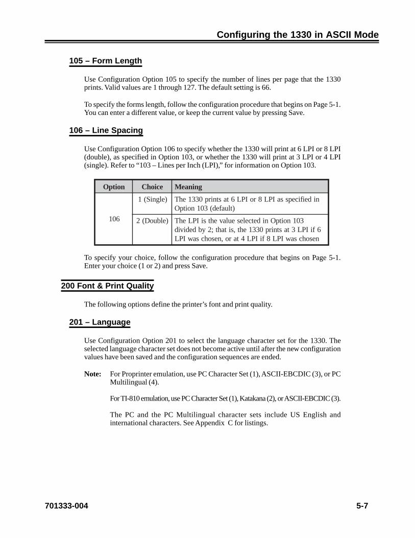
701333-004 5-7
Configuring the 1330 in ASCII Mode
105 – Form Length
Use Configuration Option 105 to specify the number of lines per page that the 1330prints. Valid values are 1 through 127. The default setting is 66.
To specify the forms length, follow the configuration procedure that begins on Page 5-1.You can enter a different value, or keep the current value by pressing Save.
106 – Line Spacing
Use Configuration Option 106 to specify whether the 1330 will print at 6 LPI or 8 LPI(double), as specified in Option 103, or whether the 1330 will print at 3 LPI or 4 LPI(single). Refer to “103 – Lines per Inch (LPI),” for information on Option 103.
noitpO eciohC gninaeM
601
)elgniS(1 nideificepssaIPL8roIPL6tastnirp0331ehT)tluafed(301noitpO
)elbuoD(2 301noitpOnidetceleseulavehtsiIPLehT6fiIPL3tastnirp0331eht,sitaht;2ybdedividnesohcsawIPL8fiIPL4taro,nesohcsawIPL
To specify your choice, follow the configuration procedure that begins on Page 5-1.Enter your choice (1 or 2) and press Save.
200 Font & Print Quality
The following options define the printer’s font and print quality.
201 – Language
Use Configuration Option 201 to select the language character set for the 1330. Theselected language character set does not become active until after the new configurationvalues have been saved and the configuration sequences are ended.
Note: For Proprinter emulation, use PC Character Set (1), ASCII-EBCDIC (3), or PCMultilingual (4).
For TI-810 emulation, use PC Character Set (1), Katakana (2), or ASCII-EBCDIC (3).
The PC and the PC Multilingual character sets include US English andinternational characters. See Appendix C for listings.

5-8 701333-004
Configuring the 1330 in ASCII Mode
noitpO eciohC gninaeM
102
1 )734egaPedoC()tluafed(teSretcarahCCP
2 )058egaPedoC(laugnilitluMCP
3 )deifidom734egaPedoC(CIDCBE-IICSA
4 anakataK–018
5 )043egaPedoC(IICSAA-RCO
6 )298egaPedoC(CIDCBEA-RCO
7 )043egaPedoC(IICSAB-RCO
8 )398egaPedoC(CIDCBEB-RCO
9 )2teSrahCCP()268egaPedoC(AwerbeH
01 )2teSrahCCP()deifidom268egaPedoC(BwerbeH
11 )deifidom268egaPedoC(CwerbeH
21 2teSretcarahCCP
Note: Language choice 3, ASCII - EBCDIC, replaces the three ASCII characters [ ] ^ with the three EBCDIC characters ¢ | ¬ respectively.
Note: Language choices 9 and 10 (Hebrew A and B) and 12 (PC Character Set 2)select PC Character Set 2. All other language selections, whether chosen fromthe operator panel or from an application, select PC Character Set 1.
To select a language character set, follow the configuration procedure that begins onPage 5-1. You can select another language character set by entering its correspondingnumber, or you can retain the current selection by pressing Save.
202 – Display Language
Configuration Option 202 is a front panel option that enables users to select the languagedisplayed on the front panel. The languages available for the option are English (default),French, and German. Some domestic units support only English.
Note: When this option is changed, a software POR occurs.
To select a language character set, follow the configuration procedure that begins onPage 5-1.

701333-004 5-9
Configuring the 1330 in ASCII Mode
203 – Mono/Dual Case
Use Configuration Option 203 to specify whether the 1330 prints in mono case (allcharacters uppercase) or dual case (characters uppercase and lowercase).
noitpO eciohC gninaeM
302
1 esacreppunidetnirperasretcarahclla–esaconoM
2 nitnessadetnirperasretcarahc–esaclauD)tluafed(esacrewoldnaesacreppu
To specify your choice, follow the configuration procedure that begins on Page 5-1.Enter your choice (1 or 2) and press Save.
204 – Bold Print Enable
Use Configuration Option 204 to enable or disable bold print. If you specify YES (byentering 1), bold print is enabled and all characters are printed in bold. If you specify NO(by entering 0), bold print occurs only when the datastream indicates that bold print is totake place.
noitpO eciohC gninaeM
402)oN(0 )tluafed(delbasidsitnirpdloB
)seY(1 delbanesitnirpdloB
To specify your choice, follow the configuration procedure that begins on Page 5-1.Enter your choice (0 or 1) and press Save.
205 – Two-Pass Print Direction
Use Configuration Option 205 to better align the two print head passes on printing thatrequires two passes.
With Choice 1, the print head makes two unidirectional passes. With Choice 2, the printhead makes one bidirectional pass. Choice 1 may give you better graphics on the printoutthan choice 2, but throughput is reduced. Choice 2 gives faster operation than choice 1.
Note: Use Choice 1 only in Graphics mode.
noitpO eciohC gninaeM
5021 sessaplanoitceridinuowtsekamdaehtnirpehT
2 )tluafed(ssaplanoitceridibenosekamdaehtnirpehT
To specify your choice, follow the configuration procedure that begins on Page 5-1.Enter your choice (1 or 2) and press Save.

5-10 701333-004
Configuring the 1330 in ASCII Mode
206 – Print Quality
With Configuration Option 206, you can choose between three print qualities, dataprocessing, data processing text, or near letter quality.
noitpO eciohC gninaeM
602
1 )tluafed(ytilauq)tfard(gnissecorpataD
2 ytilauq)txetPD(txetgnissecorpataD
3 )IPC02taton()QLN(ytilauqrettelraeN
To select the print quality, follow the configuration procedure that begins on Page 5-1.Enter your choice by pressing the appropriate number key (1, 2, or 3), or you can keepthe current print quality by pressing Save.
300 Compatibility
The following options define the printer compatibility.
301 – Vertical Tab Setting
Use Configuration Option 301 to specify how the printer handles vertical tab settings.
noitpO eciohC gninaeM
103
0 )tluafed(sbatllaraelC
211-1 hguorht311(deretnerebmunenilrofspotsbatteS)derongieradnadilavniera899
To specify your choice, follow the configuration procedure that begins on Page 5-1.Enter 0 to clear all tabs, then enter each line number for which you want to set a verticaltab. Valid line numbers are 1 through 112. Press the Save key after each line number youenter. You can enter up to 112 line numbers. When you have entered all the tab settings,press Save.
An asterisk is displayed next to each line number in which tabs are saved. If the Save keyis pressed at a line where a tab is already set, that tab is removed. Tabs are never savedafter the printer is turned off. This means that you must set tabs each time the printer ispowered on.

701333-004 5-11
Configuring the 1330 in ASCII Mode
302 – Define Horizontal Tab (810)
Use Configuration Option 302 to specify if the 1330 will perform a horizontal tab in TI-810 mode, either as a TI-810 specified horizontal tab or as an IBM Proprinter specifiedhorizontal tab.
noitpO eciohC gninaeM
2030 )tluafed(batlatnoziroh018-IT=TH
1 batlatnozirohretnirporP=TH
To specify your choice, follow the configuration procedure that begins on Page 5-1.Enter your choice (0 or 1) and press Save.
303 – Carriage Return Definition
Configuration Option 303 is used to define the carriage return. You can choose a carriagereturn or a carriage return with a line feed.
noitpO eciohC gninaeM
3031 )tluafed(nruteregairrac=RC
2 deefenilhtiwnruteregairrac=RC
To make your choice, follow the configuration procedure that begins on Page 5-1. Enter1 for carriage return or 2 for carriage return with line feed, and press Save.
304 – Line Feed Definition
Use Configuration Option 304 to specify if the 1330 will perform a line feed or a linefeed combined with a carriage return.
noitpO eciohC gninaeM
4031 )tluafed(deefenil=FL
2 nruteregairrachtiwdeefenil=FL
To specify your choice, follow the configuration procedure that begins on Page 5-1.Enter your choice (1 or 2) and press Save.

5-12 701333-004
Configuring the 1330 in ASCII Mode
305 – Automatic Perforation Skip
Use Configuration Option 305 to specify whether or not the printer automatically skipsa form perforation. If this option is enabled, the printer skips three lines at the end ofeach page.
noitpO eciohC gninaeM
5030 )tluafed(piksnoitarofrepcitamotuaelbasiD
1 piksnoitarofrepcitamotuaelbanE
To make your choice, follow the configuration procedure that begins on Page 5-1. Enter1 to enable automatic perforation skip or 2 to disable automatic perforation skip, andpress Save.
306 – Ignore Sign
Configuration Option 306 ignores ANSI CRT control codes and the printer Deselectcommand when received in the datastream. This option only affects TI-810 emulation.
noitpO eciohC gninaeM
603
0 lortnoc018sasedoclortnocTRCISNAssecorP)tluafed(dnammoctceleseDtpeccadnasedoc
1 ehterongidnasedoclortnocTRCISNAerongIdnammoctceleseD
To specify your choice, follow the configuration procedure that begins on Page 5-1.Press the Right Arrow or Left Arrow key to make your choice. Then press the Save keyto make your choice the active selection.
Note: The Up Arrow and Down Arrow keys cannot be used to get to this option.
307 – Bit Graphics
Configuration Option 307 enables and disables Proprinter Bit Graphics escape commandsand the Shift-In (SI) command. This option only affects the Proprinter emulation mode.
noitpO eciohC gninaeM
703
0 dnammocISehtdnascihparGtiBretnirporPelbasiD
1 dnammocISehtdnascihparGtiBretnirporPelbanE)tluafed(
To specify your choice, follow the configuration procedure that begins on Page 5-1.Press the Right Arrow or Left Arrow key to make your choice. Then press the Save keyto make your choice the active selection.

701333-004 5-13
Configuring the 1330 in ASCII Mode
308 – BC Space CHR
Configuration Option 308 enables and disables the processing of the ANSI Space characteras an actual bar code character. With this Option disabled, the ANSI Standard rulesapply to the processing of Space characters. With this Option enabled, the ANSI Spacecharacter is processed as an actual bar code character and the ANSI comma characterserves as a bar code separator as well as a space character to move the print position onespace to the right.
noitpO eciohC gninaeM
803
0 rabasaretcarahcecapSehtfognitnirpehtelbasiD)tluafed()dradnatSISNA(retcarahcedoc
1 rabasaretcarahcecapSehtfognitnirpehtelbanE)dradnatSIICSA4224(retcarahcedoc
To specify your choice, follow the configuration procedure that begins on Page 5-1.Press the Right Arrow or Left Arrow key to make your choice. Then press the Save keyto make your choice the active selection.
Note: This option does not affect 4224 ASCII bar codes.
309 – Bar Code Control
Use Configuration Option 309 to configure the ANSI bar code printout.
noitpO eciohC gninaeM
903
1 ehtnitnofedocrabdradnatsehtsesU–dradnatSdedecerpeblliwedocrabISNAdradnatS.retnirp
.ecapsetihwfohcninafo4/1ybdewollofdna)tluafed(
2 rabtnerrucehtnehW.devreseR–tnoFdesserpmoCottluafed,elbaliavatonsitnofdesserpmocedoc
.ezisdradnats
3 ebotpudevomsielbadaernamuhehT–IRHresolCfohcninafo4/1ehT.flestiedocrabehtotresolcedocrabehtswollofdnasedecerptahtecapsetihw
.devomerera
To specify the bar code control default, follow the configuration procedure that beginson Page 5-1. Enter your choice (1, 2, or 3) and press Save.

5-14 701333-004
Configuring the 1330 in ASCII Mode
400 Printer Setup
The following options define the printer setup.
401 – Save Operator Format
Configuration Option 401 lets you specify a default print format or an operator selectedprint format. The 1330 normally powers on with all printer format parameters set to theirfront panel values. However, you can specify that the 1330 power on with the defaultprinter format values.
The default printer format values are these:
• Lines per inch (LPI) = 6
• Maximum print position (MPP) = 132 (136 for ASCII)
• Maximum page length (MPL) = 66
• Characters per inch (CPI) = 10
• Line spacing = Single
• Case = Dual
• Left margin = 1
• Base color = 1
Note: For IPDS defaults, see Appendix B of this manual.
If you choose an operator selected print format for Option 401, the last value saved foreach parameter becomes the new default value when the printer is powered on.
noitpO eciohC gninaeM
104)oN(1 tamrofdetcelesrotarepoevastonoD
)seY(2 )tluafed(tamrofdetcelesrotarepoevaS
To specify your choice, follow the configuration procedure that begins on Page 5-1.Enter your choice (1 or 2) and press Save.
402 – Key Alarm
Use Configuration Option 402 to specify whether a beep sounds each time a key on thetouchpad is pressed. If you specify NO (by entering 0), the touchpad does not produceaudible feedback.
noitpO eciohC gninaeM
204
)oN(0 desserpsiyekanehwdnuostonseodmralaehT)tluafed(
)seY(1 desserpsiyekanehwsdnuosmralaehT
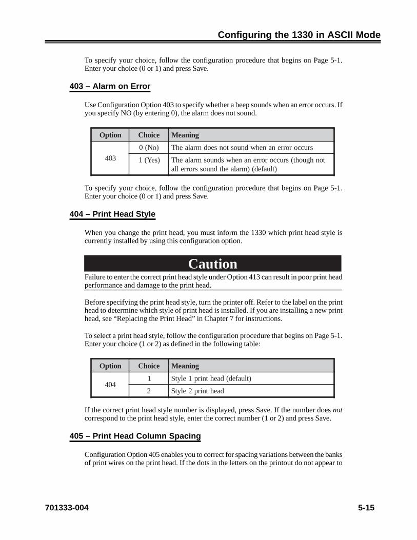
701333-004 5-15
Configuring the 1330 in ASCII Mode
To specify your choice, follow the configuration procedure that begins on Page 5-1.Enter your choice (0 or 1) and press Save.
403 – Alarm on Error
Use Configuration Option 403 to specify whether a beep sounds when an error occurs. Ifyou specify NO (by entering 0), the alarm does not sound.
noitpO eciohC gninaeM
304
)oN(0 sruccororrenanehwdnuostonseodmralaehT
)seY(1 tonhguoht(sruccororrenanehwsdnuosmralaehT)tluafed()mralaehtdnuossrorrella
To specify your choice, follow the configuration procedure that begins on Page 5-1.Enter your choice (0 or 1) and press Save.
404 – Print Head Style
When you change the print head, you must inform the 1330 which print head style iscurrently installed by using this configuration option.
CautionFailure to enter the correct print head style under Option 413 can result in poor print headperformance and damage to the print head.
Before specifying the print head style, turn the printer off. Refer to the label on the printhead to determine which style of print head is installed. If you are installing a new printhead, see “Replacing the Print Head” in Chapter 7 for instructions.
To select a print head style, follow the configuration procedure that begins on Page 5-1.Enter your choice (1 or 2) as defined in the following table:
noitpO eciohC gninaeM
4041 )tluafed(daehtnirp1elytS
2 daehtnirp2elytS
If the correct print head style number is displayed, press Save. If the number does notcorrespond to the print head style, enter the correct number (1 or 2) and press Save.
405 – Print Head Column Spacing
Configuration Option 405 enables you to correct for spacing variations between the banksof print wires on the print head. If the dots in the letters on the printout do not appear to

5-16 701333-004
Configuring the 1330 in ASCII Mode
be aligned vertically, Option 405 can be used to correct this condition. Valid values rangefrom 90 to 100. The default is 95. Refer to “Checking Character Width” in Chapter 7 forcomplete instructions.
••••••••
••••••••tcerroC tcerrocnI
Figure 5-1. Aligned and Unaligned Dots in Characters
406 – Ribbon Type Override
Configuration Option 406 enables you to override the type of ribbon installed in theprinter.
noitpO eciohC gninaeM
604
0 )tluafed(edirrevoon–rosnesepytnobbiresU
1 nobbir)roloc-4(tnecca–epytnobbiredirrevO
2 nobbir)roloc-8(evitcartbus–epytnobbiredirrevO
3 nobbiremorhconom–epytnobbiredirrevO
In normal operation, the default should be used. The other choices enable the printer tobe used with a faulty ribbon or ribbon sensor. The other choices are not recommendedunless the ribbon or sensor is faulty.
To specify your choice, follow the configuration procedure that begins on Page 5-1.Enter your choice (0, 1, 2, or 3) and press Save.
407 – Ribbon Track Select Adjustment
Configuration Option 407 enables you to adjust the home position of the ribbon trackselect mechanism. If the printout is showing a color mix, Option 407 can be used tocorrect this condition. Valid values are 0 through 10. The default is 2.
To adjust the home position, follow the configuration procedure that begins on Page 5-1.When TRAK SEL ADJ displays in the status window, it will be followed by the currentvalue. If the printout has a color mix at the top of the characters, enter a lesser value. Ifthe printout shows a color mix at the bottom of the characters, enter a greater value. Youcan keep the current value by pressing Save.

701333-004 5-17
Configuring the 1330 in ASCII Mode
408 – Module Type Override
Use Configuration Option 408 to override the type of forms module installed in theprinter. Enter 0 to disable the override and use the module sensor or enter 1, 2, or 3 tooverride the Document Insertion Device (DID) option, the Document on Demand (DOD)option, or the Continuous Forms module.
noitpO eciohC gninaeM
804
0 )tluafed(edirrevoon–rosneseludomesU
1 eludomsmroFsuounitnoC–epyteludomedirrevO
2 dnameDnotnemucoD–epyteludomedirrevOnoitpo)DOD(
3 eciveDnoitresnItnemucoD–epyteludomedirrevOnoitpo)DID(
To specify your choice, follow the configuration procedure that begins on Page 5-1.Enter your choice (0, 1, 2, or 3) and press Save.
409 – Auto Eject
Configuration Option 409 enables automatic Document on Demand (DOD) paper eject.You can select the amount of time to wait by adjusting the value of Option 409. UseOption 410, Auto Return, to set the time the printer waits after receiving new data toreturn forms to the print position.
noitpO eciohC gninaeM
904
00 )tluafed(remittcejeDODcitamotuaelbasiD
552-1 sahgnitnirpretfatiawotsdnocesforebmunehTegapgnitcejeyllacitamotuaerofebdeppots
To specify your choice, follow the configuration procedure that begins on Page 5-1.Enter your choice and press the Save key.
Note: For this option to work, the Forms Handler module must be installed. If anothermodule is installed, this option is ignored.
410 – Auto Return
Configuration Option 410 sets a timer used by the automatic Document on Demand(DOD) paper return. The value of Option 409 (Auto Eject) must be greater than zero forAuto Return to have an effect. You can select the amount of time to wait beforeautomatically returning the paper by adjusting the value of Option 410.

5-18 701333-004
Configuring the 1330 in ASCII Mode
noitpO eciohC gninaeM
014
00 txenehtnehwgninrawonhtiwyllacitamotuanruteRgnissecorprofydaersitnirp
552-1 sitnirptxenehtretfatiawotsdnocesforebmunehTgninruteryllacitamotuaerofebgnissecorprofydaer
)sdnoces5=tluafed(noitisoptnirptxenehtot
To specify your choice, follow the configuration procedure that begins on Page 5-1.Enter your choice and press the Save key.
Note: If the value is greater than 0, the alarm will sound as a warning that the printeris about to retract the paper to the next print position to continue processingdata.
411 – Paper Eject Adjustment
Configuration Option 411 is used in conjunction with the Forms Handler module. Withthis option, you can adjust the distance the paper moves when you press the Load/Ejectkey while the DOD option is installed. Valid values are 0 through 255. The default settingis 127.
To adjust the paper eject distance, follow the configuration procedure that begins onPage 5-1. If you enter a value greater than the current value, the paper ejects higher. Ifyou enter a lesser value, the paper ejects lower. You can keep the current value by pressingSave.
412 – Horizontal Offset
The 1330 uses a fixed position paper tractor on the left side. To adjust the location of thefirst print position, use Configuration Option 412. Values range from 0 through 127.Units are in increments of 0.007 inch (0.02 cm), so the offset is between 0 and 0.88 inch(0 to 2.24 cm). The default setting is 0.
To specify your choice, follow the configuration procedure that begins on Page 5-1.Enter your choice (from 0 to 127) and press Save.
Note: If you go to this feature frequently, you may want to use a shortcut to its options.Follow this procedure: In Ready mode press the Option key. That will take youto Express 412, where you can use the arrow keys to select the values as younormally would. Once you have chosen the values you want, press the Start keyand your setup will be saved.

701333-004 5-19
Configuring the 1330 in ASCII Mode
413 – Horizontal Registration
Configuration Option 413 enables you to adjust the printed line horizontally for verticalcharacter alignment. Values range from 0 through 255. The default setting is 127. Unitsare in increments of 0.0007 inch (0.002 cm). This option is used with bidirectional printingonly. For complete instructions, refer to “Checking Print Registration” in Chapter 7.
To specify your choice, follow the configuration procedure that begins on Page 5-1.Enter your choice (from 0 to 255) and press Save.
414 – Paper Jam Sensor Enable
Use Configuration Option 414 to enable or disable the paper jam sensor. If you specifyNO (by entering 0), the paper jam sensor is disabled.
noitpO eciohC gninaeM
414)oN(0 delbasidsirosnesmajrepapehT
)seY(1 )tluafed(delbanesirosnesmajrepapehT
To specify your choice, follow the configuration procedure that begins on Page 5-1.Enter your choice (0 or 1) and press Save.
415 – Paper Out Sensor Enable
Configuration Option 415 enables and disables the paper out sensor. If the paper outsensor is disabled, the alarm is prevented from sounding when the printer is out of paper.
WarningWhen the paper out sensor is disabled, the printer cannot detect a paper out condition. Ifthe printer continues printing without paper for an extended period, the print head couldbe damaged.
noitpO eciohC gninaeM
514)oN(0 delbasidsirosnestuorepapehT
)seY(1 )tluafed(delbanesirosnestuorepapehT
To specify your choice, follow the configuration procedure that begins on Page 5-1.Enter your choice (0 or 1) and press Save.

5-20 701333-004
Configuring the 1330 in ASCII Mode
416 – Paper Skew Sensor Enable
Use Configuration Option 416 to enable or disable the paper skew sensor. If you specifyNO (by entering 0), the paper skew sensor is disabled.
Note: Paper skew is checked only when the Forms module is in DID mode.
noitpO eciohC gninaeM
614)oN(0 delbasidsirosnesweksrepapehT
)seY(1 )tluafed(delbanesirosnesweksrepapehT
To specify your choice, follow the configuration procedure that begins on Page 5-1.Enter your choice (0 or 1) and press Save.
418 – DOD Load Adjust
Use Configuration Option 418 to set the distance between the top of the form and thebottom of the characters in the first print line. Values range from 20 to 255, in .007-inchincrements. For example, if you have a box you want to print in as the first print line,measure the distance from the physical top of the form to the line you want to print on.Convert the distance to .007 inches and enter the distance as the value for the LoadAdjust parameter.
Note that you will only be able to access the option that corresponds to the device youhave in the printer; that is, if you have a DOD device, the menu will only allow you toaccess the DOD Load Adjust option. Loads can be initiated in Stop or Ready mode witha DID device, but only in Ready mode with a DOD device.
419 – DID Load Adjust
Use Configuration Option 419 to set the distance between the top of the form and thebottom of the characters in the first print line. Values range from 20 to 255, in .007-inchincrements. For example, if you have a box you want to print in as the first print line,measure the distance from the physical top of the form to the line you want to print on.Convert the distance to .007 inches and enter the distance as the value for the LoadAdjust parameter.
Note that you will only be able to access the option that corresponds to the device youhave in the printer; that is, if you have a DID device, the menu will only allow you toaccess the DID Load Adjust option. Loads can be initiated in Stop or Ready mode witha DID device, but only in Ready mode with a DOD device.

701333-004 5-21
Configuring the 1330 in ASCII Mode
421 – Operator Panel Adjust
Use Configuration Option 421 to adjust the intensity of the LCD on the Operator Panel.The intensity ranges from light to dark.
noitpO eciohC gninaeM
124
1 thgiL
2 )tluafed(lamroN
3 kraD
To specify your choice, follow the configuration procedure that begins on Page5-1. Enter your choice (1, 2, or 3) and press Save.
422 – Start Mode After Eject
Configuration Option 422 enables you to set the 1330 so that it automatically goes intoready mode when you press the Load key twice. This will also cause the paper to retract.
noitpO eciohC gninaeM
224
seY nehwedomydaerotniseogyllacitamotua0331ehT)tluafed(eciwtyekdaoLehtsesserpresueht
oN tcejeretfaedompotSnisniamer0331ehT
To specify your choice, follow the configuration procedure that begins on Page 4-1.Enter your choice (Yes or No) and press Save.
423 – Report Intervention
Configuration Option 423 enables you to set the 1330 so that interventions are or are notreported to the host.
noitpO eciohC gninaeM
324seY )tluafed(tsohehtotsnoitnevretnistroper0331ehT
oN tsohehtotsnoitnevretnitropertonseod0331ehT
To specify your choice, follow the configuration procedure that begins on Page 4-1.Enter your choice (Yes or No) and press Save.

5-22 701333-004
Configuring the 1330 in ASCII Mode
500 Communication
The following options define the printer’s communication selections.
501 – Printer Emulation Mode
Configuration Option 501 selects the printer emulation.
noitpO eciohC gninaeM
105
1 )tluafed(retnirporP
2 018-IT
5-3 devreseR
To specify your choice, follow the configuration procedure that begins on Page 5-1.Enter your choice and press the Save key.
For a listing of the commands supported in each emulation, refer to Appendix B of thismanual.
502 – Buffer Size
Configuration Option 502 enables you to select the effective size of the 1330’s input orcommunications buffer:
noitpO eciohC gninaeM
205
1 )tluafed(reffubK2
2 reffubK8
3 reffubK61
4 )mumixam(reffubK23
To select buffer size, follow the configuration procedure that begins on Page 5-1. Enteryour choice (1, 2, 3, or 4) and press Save.
503 – DC1/DC3 Recognition
Configuration Option 503 enables or disables the printer’s recognition of DC1/DC3characters. This option enables the host to control the online/offline state of the printer.
noitpO eciohC gninaeM
3050 noitingocerelbasiD
1 )tluafed(noitingocerelbanE

701333-004 5-23
Configuring the 1330 in ASCII Mode
To specify your choice, follow the configuration procedure that begins on Page 5-1.Enter your choice and press the Save key.
504 – Baud Rate
Configuration Option 504 selects the printer baud rate. The printer baud rate must matchthat of the host.
noitpO eciohC gninaeM
405
1 )ylno224-SR(K65
2 )ylno224-SR(K4.83
3 K2.91
4 )tluafed(0069
5 0084
6 0042
7 0021
8 006
9 003
01 051
11 011
To specify your choice, follow the configuration procedure that begins on Page 5-1.Enter your choice and press the Save key.
505 – Parity
Configuration Option 505 selects the printer parity. Parity must match that of the host.
noitpO eciohC gninaeM
505
0 ytirapoN
1 ytirapddO
2 )tluafed(ytirapnevE
To specify your choice, follow the configuration procedure that begins on Page 5-1.Enter your choice and press the Save key.

5-24 701333-004
Configuring the 1330 in ASCII Mode
506 – Data Bits
Configuration Option 506 selects 7-bit or 8-bit data. This selection must match that ofthe host.
noitpO eciohC gninaeM
6051 )tluafed(atadtib-7tceleS
2 atadtib-8tceleS
To specify your choice, follow the configuration procedure that begins on Page 5-1.Enter your choice and press the Save key.
507 – Stop Bits
Configuration Option 507 selects one or two stop bits. This selection must match that ofthe host.
noitpO eciohC gninaeM
7051 )tluafed(tibpotsenotceleS
2 stibpotsowttceleS
To specify your choice, follow the configuration procedure that begins on Page 5-1.Enter your choice and press the Save key.
508 – Modem Control
Configuration Option 508 selects whether the printer will recognize or ignore DCD/DSR modem control signals.
noitpO eciohC gninaeM
805
0 slangislortnocmedomRSD/DCDerongI
1 slangislortnocmedomRSD/DCDezingoceR)tluafed(
To specify your choice, follow the configuration procedure that begins on Page 5-1.Enter your choice and press the Save key.

701333-004 5-25
Configuring the 1330 in ASCII Mode
509 – Handshaking
Configuration Option 509 controls host-printer handshaking.
noitpO eciohC gninaeM
905
1 gnidnespotsottsohotFFOXdnes–FFOX/NOX)tluafed(
2 RTDnoysubtondnaenilnoetacidni–RTDotysuBenil
3 ecafretninoysubetacidni–lennahcesreveR11niprotcennoc
4 ton,ecafretnignitoohselbuortrofdesu–enoNdesuyllamron
To specify your choice, follow the configuration procedure that begins on Page 5-1.Enter your choice and press the Save key.
510 – (Reserved)
511 – RS-422 Polarity
Configuration Option 511 controls the polarity of the RS-422 receive and transmit signals.
noitpO eciohC gninaeM
1150 ytiralopehttrevnI
1 )tluafed(ytiralopehttrevnitonoD
To specify your choice, follow the configuration procedure that begins on Page 5-1.Enter your choice and press the Save key.

5-26 701333-004
Configuring the 1330 in ASCII Mode
600 Attachment
The following options define the printer’s attachment selections.
601 – Interface
Configuration Option 601 enables you to manually select the 3270 or ASCII interfacefrom the dual interface card when installed in the 1330 printer.
noitpO eciohC gninaeM
106
0 ecafretni0723ehtfoesuehterugifnoC
1 ecafretniIICSAehtfoesuehterugifnoC
2 fitluafeD(secafretniIICSAdna0723ehthtoberahS)dellatsnisidraobecafretnilaud
To specify your choice, follow the configuration procedure that begins on Page 5-1.Enter your choice (0 or 1) and press Save. The 1330 will automatically reinitialize to theinterface chosen.
Note: The keypad options will change based on the selection you make.
Note: Option 601 will not appear if the dual interface card is not installed.
602 – Idle Timeout
Use Configuration Option 602 to specify the number of seconds that must elapse with noactivity in the active mode before the printer enters idle mode.
noitpO eciohC gninaeM
206
0 .edomevitcanatixetonlliwretnirP
n–1 atadonsierehtnehwedomevitcanatixelliwretnirP.sdnocesnretfassecorpot
If data is present in the nonactive mode when the printer goes idle, the printer changesmode and prints the data. Otherwise the printer will remain idle until it detects data ineither interface. The range of seconds you may choose from is 0 to 99. In 3270 mode, thedefault is 30 seconds; in ASCII mode, the default is 5 seconds.

701333-004 5-27
Configuring the 1330 in ASCII Mode
Note: A value of 0 seconds means that if the printer is in the mode indicated by theoption or when it enters that mode, it will remain in that mode until this optionis changed to a nonzero value or until power is cycled.
603 – Interface Type
Configuration Option 603 selects the interface type.
noitpO eciohC gninaeM
306
0 )tluafed(lellaraP
1 232-SR
2 224-SR
To specify your choice, follow the configuration procedure that begins on Page 5-1.Enter your choice and press the Save key.
700 Extended Keypad
The following options define the extended keypad.
701 – Print Configuration
Use Configuration Option 701 to print a list of the current configuration values. To printthis list, follow the configuration procedure that begins on Page 5-1. When the secondline of the display reads PRINT CONFIG, press the Save key. The printer prints a list ofoption numbers, followed by their current values. See Figure 5-2 for a sample configurationvalue printout.
Note: The sample printout on the following pages shows all the printer default values.

5-28 701333-004
Configuring the 1330 in ASCII Mode
PRINTER TYPE: 1330/6573-X
PC MC IORELEASE LEVEL: 01 01 01
PATCH LEVEL: 02 00 01
RAM: A0000
CHECKSUMS: 26A1 FC24
DUAL INTERFACE BOARD INSTALLED
CFD MODULE
SUBTRACTIVE RIBBON
ASCII CONFIGURATION
*** PAGE FORMAT ***101 LEFT MARGIN 01102 CPI 1(10)103 LPI 1 (6)104 MPP 136105 FORM LENGTH 66106 LINE SPACING 1 Single
*FONT & PRT QUALITY*201 LANGUAGE 01 PC Char Set202 DISPLAY LANG 0 English203 CASE 2 Dual204 BOLD PRINT 0 Disable205 BIDIR 2 PAS PRT 2 Bidirectional206 PRINT QUALTY 1 DP
** COMPATIBILITY **301 VERTI TAB SETUP 00302 DEF HORIZ TAB 0 810 (Default)303 DEFINE CR 1 CR = CR304 DEFINE LINEFEED 1 LF = LF305 PERFORATN SKIP 0 Disable306 IGNORE SCREEN 0 Disable307 BIT GRAPHICS 1 Enable308 BC SPACE CHR 0 Disable309 BAR CODE CONTROL 1 Standard
Figure 5-2. Configuration Value Printout (ASCII)(Continued on next page)

701333-004 5-29
Configuring the 1330 in ASCII Mode
*** PRINTER SETUP ***401 OPERATOR FORMAT 2 Saved402 KEY ALARM 0 No Sound403 ALARM ON ERROR 1 Yes404 PRNT HEAD STYL 1405 PRT HD COL SPAC 95406 RIBBON TYPE 0 Use Sensor407 RB TRAK SEL ADJ 05408 MODULE TYPE 0 Use Sensor409 AUTO EJECT 00410 AUTO RETURN ADJ 05411 EJECT ADJUSTMENT 127412 HORZ OFFSET 14413 HORZ REGSTRN 127414 PAPER JAM 1 Enable Sensr415 PAPER OUT 1 Enable Sensr416 PAPER SKEW 1 Enable Sensr
** COMMUNICATION **501 PRINTER EMULTN 1 PROPRINTER502 BUFFER SIZE 1 2K503 DC1 / DC3 1 Recognize504 BAUD RATE 4 ( 9600 )505 PARITY 2 Even506 DATA BITS 1 Seven507 STOP BITS 1 One508 MODEM CONTROL 1 DCD/DSR Used509 HANDSHAKING 1 XON/XOFF510 (RESERVED)511 RS422 POL 1 Dont Invert
**** ATTACHMENT ****601 INTERFACE 2 Share602 IDLE TIMEOUT 05603 ASCII INTERFACE 0 PARALLEL
* EXTENDED KEYPAD **704 POR CUSTOM SET 00
Figure 5-2. Configuration Value Printout (ASCII)(Continued from previous page)

5-30 701333-004
Configuring the 1330 in ASCII Mode
702 – Quick Reference
Use Configuration Option 702 to list all possible option values associated with eachoption.
703 – Set Factory Defaults
Configuration Option 703 is used to reinitialize the nonvolatile RAM (NVRAM). Allconfiguration values will be reset to the factory default values except the following (theseoptions can only be changed by selecting them in Options mode):
• Horizontal Registration
• Print Head Pulse Width
• Print Head Column Spacing
• Print Head Type
• Character Count
• Track Select Adjust
In Stop mode, press the Option key. Follow the configuration procedure that begins onPage 5-1 to bring up this option. Pressing the Save key will reinitialize the NVRAM. Theprinter will do a power-on reset.
Note: Both the 3270 and ASCII settings are reset to factory defaults.
704 – POR Custom Set
Configuration Option 704 specifies the custom set that will be copied into the current setduring POR. A soft POR will occur when you exit this option.
noitpO eciohC gninaeM
4070 )tluafed(deifidomnusniamertestnerrucehT
4–1 4hguorht1tesmotsuC
To use this option, follow the configuration procedure that begins on Page 5-1.

701333-004 5-31
Configuring the 1330 in ASCII Mode
705 – Save Custom Set
Configuration Option 705 specifies which custom set you will immediately copy thecurrent set into.
noitpO eciohC gninaeM
507 4–1 4hguorht1tesmotsuC
To use this option, follow the configuration procedure that begins on Page 5-1.
706 – Recall Custom Set
Configuration Option 706 specifies which custom set you will immediately recall as thecurrent set. A soft POR will occur when you exit this option.
noitpO eciohC gninaeM
607 4–1 4hguorht1tesmotsuC
To use this option, follow the configuration procedure that begins on Page 5-1.
707 – Display Character Count
Configuration Option 707 displays the current character count on the status display. Usethis option to record the character count each time you change the print head, so thatCustomer Service can better service the 1330.
The character count is displayed as n,nnn,nnn,nnn, with the appropriate n’s reading asnumber values to reflect the current character count. For example, if the character countis 1,220,000 characters, the display reads 0001220000. Record the character count onthe form provided in Appendix E each time you change the print head. The maximumvalue for the character count is 9,999,999,999. Note these two points about the charactercount:
• The character counter will count only characters, not graphics.
• Draft and near letter quality characters are counted equally, one per character. Printhead life, however, is based on draft characters only.
To view the character count, follow the configuration procedure that begins on Page 5-1.When DISP CHR CNT appears on the second line of the display, press the Save key todisplay the current character count. Record this figure on the form in Appendix E.
The displayed character count cannot be changed during this configuration option.

701333-004 6-1
Chapter 6. Operating the 1330
Operating procedures for the 1330 can be divided into three categories:
• Setting the print format
• Specific operating procedures
• General operating procedures
Setting the Print Format
The print format consists of four parameters: characters per inch, line length (maximumprint position), forms length, and vertical line density.
The following points explain 1330 print format:
• The number of characters per inch (CPI) can be selected by using ConfigurationOption 102. You can choose 10, 12, 15, 16.7, 17.1, or 20 CPI. When the CPI ischanged, the line length correspondingly changes. See “Setting the Line Length”in this chapter for the maximum print position (line length) that corresponds toeach CPI setting.
• The line length is the distance, in character widths, between the first (leftmost)print position and the last print position. Line length is commonly indicated by themaximum print position (MPP) (Option 104).
• The forms length is the length of the forms in lines. To calculate the forms length,multiply the length of the paper in inches by the lines per inch (LPI) setting (Option105).
For example, if your forms are 11 inches long, and the LPI setting is 8, the formslength in lines is 88.
• The vertical line density consists of the lines per inch setting and the single space/double space setting (Option 103) as outlined below:
ytisneDeniLlacitreV IPL8/6 ecapSelbuoD/elgniS
IPL8 IPL8 elgniS
IPL6 IPL6 elgniS
IPL4 IPL8 elbuoD
IPL3 IPL6 elbuoD
Note: The LPI value, CPI value, forms length value, and maximum print positionvalue can be overridden by the host application system. The Change Case andChange Space option settings are not overridden by the host system.

6-2 701333-004
Operating the 1330
If no operator set values have been saved for the print format settings, that is, choice 2has been saved for Configuration Option 401 (see Chapter 4), the 1330 assumes thefollowing default values:
noitcnuF tluafeD
hcnIrePsretcarahC 01
htgneLeniL )IICSArof631(231
htgneLsmroF 66
hcnIrePseniL IPL6
The following sections describe the procedures for setting each print format parameterfor the 1330.
Specific Operating Procedures
Specific operating procedures include the following:
• Specifying mono case or dual case (see Option 203)
• Printing the setup line
• Adjusting the top of form position
• Setting the alarm control (see Option 402)
• Storing printer configuration values
Printing the Setup Line
Printing the setup line allows you to visually inspect character spacing, line length, leftmargin position, and forms alignment. If you press the Form Feed key after printing thesetup line, you can visually verify the forms length and line spacing.
1. Press the Stop key to place the 1330 in Stop mode.
2. Press the Setup key to print the setup line.
3. To return to Start mode, press the Start key.

701333-004 6-3
Operating the 1330
Adjusting the Top of Form Position
Once you have printed the setup line, you can visually verify the top of form position, aswell as the left and right margins of the print line. If you want to fine adjust the top ofform position, follow these steps:
1. Press Stop to place the 1330 in Stop mode.
2. Press the Form Feed key to advance the forms to the next top of form position.
3. To fine adjust the top of form position, press the Up Arrow key or Down Arrow key.Each time you press one of these keys, the form is moved 0.007 inch (0.18 mm).
4. Press the Top of Form key to inform the 1330 of the new location.
5. To check the top of form, press the Form Feed key.
6. To return the 1330 to Start mode, press the Start key.
Storing Printer Configuration Values
You can configure the printer differently for various types of print jobs, save theseconfigurations in separate custom sets, and recall a specific custom set for particularprint jobs. However, some of the configuration options that do not generally need to bechanged for different types of print jobs are not included in the custom set. In 3270mode, these options include the following:
• Horizontal Offset
• Horizontal Registration
• Print Head Pulse Width
• Print Head Column Spacing
• Print Head Type
• Character Count
• Track Select Adjust
• Vital Product Data User Information
• Vital Product Data Serial Number
• POR Custom Set
In ASCII mode, the following options are not included in custom sets:
• ASCII Interface
• ASCII Baud Rate
• ASCII Data Bits

6-4 701333-004
Operating the 1330
• ASCII Modem Control
• ASCII IRC
• ASCII Buffer Size
• ASCII Recognize DC1/DC3
• ASCII Parity
• ASCII Stop Bits
• ASCII Handshaking
• ASCII RS-422 Invert
These options will stay in effect for the printer no matter which custom set you are using.For the remaining option settings, you can save them to one of four available custom setsby using Option 705, Save Custom Set.
Any custom set may be recalled at any time by using Option 706, Recall Custom Set. Asoft POR will occur when you exit this option that will put any changes into effect.
By using Option 704, POR Custom Set, you can also specify which custom configurationsetting to bring up when the printer is powered on. If the printer loses power accidentallybefore the current configuration is saved to any of the custom sets, you can still recallthat set of configurations by using a POR if Option 704 is configured to 0.
All of the custom sets are initially set to the factory default values. If you need to resetthe current setting to the factory defaults by using Option 703, Set Factory Defaults, thevalues saved in the custom sets are not affected. For details about custom set options, seeChapter 4.
General Operating Procedures
General operating procedures for the 1330 consist of the following:
• Reprinting the print buffer
• Requesting a host application program in SCS mode
• Halting a print operation in SCS mode
Reprinting the Print Buffer
If you encounter an out of forms or paper jam condition during a print operation, you canstart the current print job over by reprinting the print buffer. Since the data is deletedfrom the print buffer when a print job is completed, you cannot reprint the print bufferafter the print job has completed. However, if your job was interrupted, the reprint bufferoperation will allow you to reprint the entire message.

701333-004 6-5
Operating the 1330
To reprint the print buffer, follow these steps:
1. Press Stop to place the 1330 in Stop mode.
2. Correct any problems that need attention.
3. Press Form Feed to advance the forms to the first line of the next page.
4. Go to Buffer Reprint (Option 710) and press Save.
5. To return to Start mode and resume printing, exit Option mode and press the Startkey.
Note: In SCS operations, the buffer cannot be reprinted. For this reason, when you useBuffer Reprint in SCS operations, the 1330 sends an Intervention Required (IR)message requesting that the last set of data be retransmitted.
Requesting a Host Application Program in SCS Mode
SCS users can use the Program Attention (PA1 and PA2) key functions to request anapplication program from the host. Follow these steps to use the PA1 or PA2 key function:
1. Press Stop to put the 1330 in Stop mode.
2. Enter Menu mode.
3. Select Option 708 for PA1.
or
Select Option 709 for PA2.
4. Press the Save key.
5. Return to Start mode.
Halting a Print Operation in SCS Mode
To cancel a print operation in SCS mode, follow these steps:
1. Press Stop to place the 1330 in Stop mode.
2. Press the Cancel Print key to halt printing and clear the print buffer.
To suspend printing, follow these steps:
1. Press Stop. This will put the printer in Stop mode and suspend printing temporarily.
2. You can return the 1330 to Start mode by pressing the Form Feed key (to advance totop of form, if necessary), followed by Start.

701333-004 7-1
Chapter 7. Maintaining the 1330
Maintenance procedures for the 1330 include allowing adequate ventilation, cleaningthe printer, replacing and changing the print head as necessary, and adjusting the printregistration as required.
Ventilation
Inadequate ventilation of the 1330 may result in overheating, which can damage theprinter. Make sure that the vents are kept clean and free of obstructions, and that there isat least six inches (15 cm) of clearance on each side of the printer.
Cleaning the Printer
Cleaning the 1330 involves dusting it as necessary. If the cabinet requires further cleaning,use a damp cloth with a mild liquid detergent. Avoid dripping liquid into the printmechanism or onto the touchpad keys. Do not use a solvent to clean the cabinet.
Replacing the Ribbon
Chapter 2 of this manual contains complete instructions for installing the available ribbonsfor the 1330.
Replacing the Print Head
When the print head shows excessive wear – for example, when characters are formedincompletely despite a correct platen gap lever setting – the print head should be replaced.You can install a new print head by following the instructions given in this section.
Note: Before you replace the print head, check the print quality. If the dots in thecharacters are not correctly located, refer to “Checking Character Width andPrint Registration,” later in this chapter.

7-2 701333-004
Maintaining the 1330
To order a print head kit for the 1330, contact your MTX sales representative. Use thefollowing part number: 953567-001.
Note: When the 1330 has been printing for an extended time, the print head mayoccasionally slow down, start printing unidirectionally, and pause at the end ofeach line. This is not a sign of excessive wear. These conditions occurautomatically as a preventive measure when the temperature of the print headexceeds the normal operating level. As the temperature drops, the print headwill speed up and resume bidirectional printing.
To replace the print head, follow these instructions, referring to Figures 7-1 through 7-4.
WarningIf the printer has been in operation, the print head may be hot. Allow time for the printhead to cool before you attempt to change it.
1. Press the Stop key to put the printer offline, then press the Option key.
2. Use Option 707 to see the character count displayed on the status window, or useOption 701 to print out all configuration item numbers, followed by their currentvalues. Record the character count on the form provided in Appendix E of this manual.(See “707 – Display Character Count” in Chapter 4 if you need further instructionson finding the character count.)
3. Power off the printer and unplug it from the AC outlet.
4. Raise the printer cover.
5. Set the platen gap lever away from the platen (toward you) as far as it will go. If youneed instructions, refer to Chapter 2.
6. Remove the ribbon cartridge. Refer to Chapter 2 if you need instructions.
7. Slide the print head to the middle of the printer.
8. Unsnap the black plastic restraining bar to loosen the cable so you can see theconnectors.
9. Remove the connectors shown in Figure 7-1.

701333-004 7-3
Maintaining the 1330
Connectors
Figure 7-1. Replacing the Print Head
Note: Print head style 2 has a connector at the top of the print head. This connectordoes not have to be disconnected when you remove the print head.
Note: Take care that the wiring from the ribbon select motor stays through the carriagerestraining hook. Refer to Figure 7-2.
10. If it is installed, remove the tie-wrap holding the print head wires to the carriage.
Restraining Hook
Figure 7-2. Carriage Restraining Hook
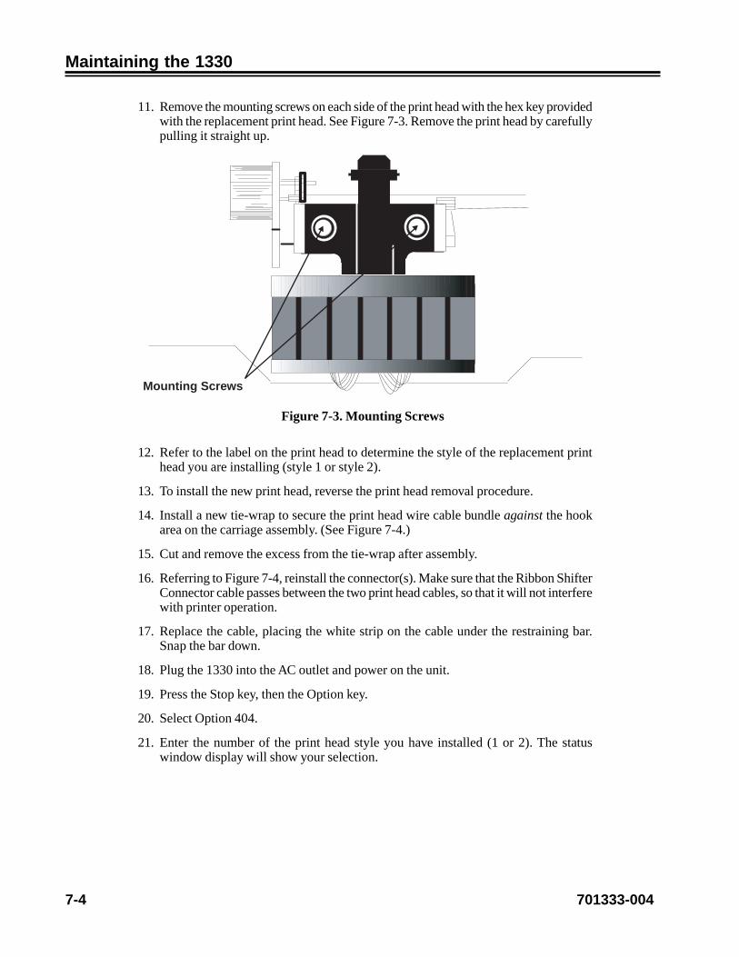
7-4 701333-004
Maintaining the 1330
11. Remove the mounting screws on each side of the print head with the hex key providedwith the replacement print head. See Figure 7-3. Remove the print head by carefullypulling it straight up.
Mounting Screws
Figure 7-3. Mounting Screws
12. Refer to the label on the print head to determine the style of the replacement printhead you are installing (style 1 or style 2).
13. To install the new print head, reverse the print head removal procedure.
14. Install a new tie-wrap to secure the print head wire cable bundle against the hookarea on the carriage assembly. (See Figure 7-4.)
15. Cut and remove the excess from the tie-wrap after assembly.
16. Referring to Figure 7-4, reinstall the connector(s). Make sure that the Ribbon ShifterConnector cable passes between the two print head cables, so that it will not interferewith printer operation.
17. Replace the cable, placing the white strip on the cable under the restraining bar.Snap the bar down.
18. Plug the 1330 into the AC outlet and power on the unit.
19. Press the Stop key, then the Option key.
20. Select Option 404.
21. Enter the number of the print head style you have installed (1 or 2). The statuswindow display will show your selection.

701333-004 7-5
Maintaining the 1330
CautionFailure to enter the correct print head style under Configuration Option 404 can result inpoor print head performance and can damage the print head.
22. Press the Save key and the Stop key. If you plan to print in data processing quality,enter 1. If you want to print in data processing text quality, enter 2. If you want toprint in near letter quality, enter 3. Press Save.
23. You can resume printing by pressing Stop until STOP is displayed, then Start.
Print Head Connector -Long
Key Location
Ribbon Shifter Connector
Hook
Figure 7-4. Carriage - Side View
Checking Character Width and Print Registration
After changing the print head, you may want to check the printed character width andprint registration. Print registration refers to the proper vertical alignment of charactersfrom line to line at the right and left margins of the printed text. When the print registrationis correct, characters are properly aligned at the margins, as shown in Figure 7-5.
HHHHHHHHHHHHHHHHHHHHHHHHHHHHHHHHHHHHHHHHHHHHHHHHHHHHHHHHHHHHHHHHHHHHHHHHHHHHHHHHHHHHHHHHHHHHHHHHHHHH
Figure 7-5. Proper Print Registration

7-6 701333-004
Maintaining the 1330
To check character width and print registration after changing the print head and beforeprinting text, you can use Option 204 in bold and normal text to print out samples of thecharacter width and registration. Make sure the print head is printing bidirectionally forseparate test results, then use Configuration Options 413 and 405 to make adjustments asnecessary. Follow these steps to check character width and print registration.
Checking Character Width
1. Load 14-inch wide (35.6-cm wide) paper in the printer. If necessary, refer to thepaper loading instructions in Chapter 2 of this manual.
2. Make sure that the 1330 is in Stop mode. If necessary, press the Stop key.
3. Use Configuration Option 204 to enable bold printing and Option 205 to enablebidirectional printing.
4. Select Option D02 under the Diagnostic menu.
5. Press the Save key to start the test. The display window will show the test numberand the message TEST IS RUNNING.
The 1330 will print columns of Hs, which will enable you to check character width.
6. Press the Stop key to stop the test. The test number and name will be displayed.
7. Examine the printout. If the character width looks consistent and you do not want toadjust it, go to Step 12.
or
If you do want to adjust the character width, go on to Step 8.
8. Press the Stop key.
9. Select Option 405.
10. Compare the Hs on the printout. If the characters with the greater than (>) symbolsare wider than the characters on the following line, you should decrease the PHCOL SPACE value. For example, if the current value is 91 and the characters are toowide, decrease the value to 90.
If the characters with the greater than symbol are narrower than the characters onthe following line, you should increase the PH COL SPACE value. For example, ifthe current value is 91, increase it to 92.
11. To verify your change, press Save and exit Menu mode. The printer will reinitialize.Go back to Step 4 of this procedure, and repeat Steps 4 through 7 until the characterwidth is acceptable in the center portion of the printout.
12. Before going on to “Checking Print Registration,” use Configuration Option 204 tocancel bold print, then exit Menu mode.

701333-004 7-7
Maintaining the 1330
Checking Print Registration
1. Make sure that 14-inch wide (35.6-cm wide) paper is loaded in the printer.
2. Make sure that the 1330 is in Stop mode. If necessary, press the Stop key.
3. Select Option D02 under the Diagnostic menu.
4. Press the Save key to start the test. The display window will show the test numberand the message TEST IS RUNNING.
The 1330 will print columns of Hs, which will enable you to check the printregistration.
5. Press the Stop key to stop the test. The test number and name will be displayed.
6. Examine the printout. If the print registration looks good and you do not want toadjust it, go to Step 11.
or
If you do want to adjust the print registration, go on to Step 7.
7. Press the Stop key.
8. Select Option 413, Horizontal Registration.
9. Compare the Hs on the printout with the (enlarged) characters in Figures 7-6 and7-7. If the characters with the greater than (>) symbol are offset to the left of thecharacters on the following line, you should increase the horizontal registrationvalue. For example, if the current value is 131 and the characters are offset to theleft, increase the value to 141.
> HHHH
HHHH
> HHHH
HHHH
> HHHH
HHHH
Figure 7-6. Increase Print Registration Value
If the characters with the greater than symbol are offset to the right of the characterson the following line, you should decrease the horizontal registration value. Forexample, if the current value is 131, decrease it to 121.

7-8 701333-004
Maintaining the 1330
> HHHH
HHHH
> HHHH
HHHH
> HHHH
HHHH
Figure 7-7. Decrease Print Registration Value
10. To verify your change, press Save and exit Menu mode. The printer will reinitialize.Go back to Step 3 of this procedure until print registration is acceptable in the centerportion of the printout.
Note: If you cannot obtain an acceptable print registration sample, or if the centerportion of the printout is acceptable, but the column of Hs to the right and left isnot properly registered, call Customer Service.
11. To return the printer to normal operation, press the Start key.
701333-004 8-1
Chapter 8. Error Detectionand Recovery
The 1330 has encountered an error condition when one or both of the following occur:
• The alarm sounds.
• An error message appears in the display window.
When either of these conditions occurs, immediately press the Stop key to place the1330 in Stop mode. If the Stop key will not work, write down the displayed error messageand call Customer Service.
Types of Errors
Three types of errors can occur on the 1330:
• Intervention required (IR) conditions
• General errors
• Unusual errors
Intervention Required Conditions
Intervention required conditions are errors that can be quickly corrected by the operator,as outlined below:
egasseMyalpsiD gninaeM
TUOREPAP10 smroffotuosiretnirpehT
MAJREPAP20 demmajerasmrofretnirpehT
WEKSREPAP40 dewekserasmrofretnirpehT
NEPOREVOC50 neposirevocretnirpehT
NOBBIRON88 retnirpehtnidellatsnisinobbiroN
See Appendix A of this manual for more complete information and recovery instructionsregarding these error conditions.

8-2 701333-004
Error Detection and Recovery
General Error Conditions
General errors are caused by hardware, software, or communications failures, and areidentified by an error message in the display window. These errors cannot be as readilycorrected by the operator and may require the assistance of a Field Engineer. Refer to theStatus and Error Message Chart in Appendix A for error descriptions and recoveryprocedures. If you cannot correct the error, power the printer off, wait 15 seconds, thenpower the printer back on. If the problem persists, contact Customer Service.
Unusual Error Conditions
If you encounter an error that is not listed in the Status and Error Message Chart(Appendix A), reset the 1330 by powering off then on to see if the error recurs. If itdoes, contact Customer Service.
If the display window goes blank, there has probably been a loss of power to the printer.Check to make sure that the power cord is plugged in, that the outlet is receiving power,and that the Power switch is set to | (ON). If the outlet is supplying the proper voltage andthe 1330 is properly plugged in, hardware trouble is apparent. Contact Customer Service.
WarningIf the unit begins to overheat, smoke, or make an unusual noise, turn off the unitimmediately! Next, unplug the power cord, remove the paper from the printer, and contactCustomer Service.
If the forms jam or tear, check to make sure that the forms are routed and aligned properly.Ensure that the form tractors are positioned properly to accommodate the paper width,that the feed holes on the forms are positioned evenly over the tractor feed pins, and thatthe tractor doors are closed. Be sure that the forms are feeding smoothly from their box,and that they are positioned correctly. Refer to Chapter 2 of this manual to review theinstructions for installing forms.
If the ribbon binds, make sure that it is routed properly. Refer to Chapter 2 to review theinstructions for installing the ribbon cartridge.
If the error cannot be determined by visual check or by the power-on Basic Assurancetest (BAT), contact the host system’s communications control center and request a checkof the communications line. If the problem persists, call Customer Service.
701333-004 A-1
Appendix A. Status and ErrorMessage Chart
egasseM noitinifeD yrevoceR
TUOREPAP10 .dellatsnisirepapoN .repapwenllatsnI
MAJREPAP20 .demmajsirepaP ehtllatsnierdnarepapdemmajehtraelC.repap
DTCEJESMROF30 ehtretfasmrofehtdetceje0331ehTedocsihT(.desserpsawyektcejE/daoL
mrofDODehtnehwylnodeyalpsidsi).desugniebsiecived
ehtdaolerotyektcejE/daoLehtsserP.smrof
WEKSREPAP40 erasmrofehttahtdesnes0331ehT.yltcerrocnidedaol
.smrofehtllatsnieR
NEPOREVOC50 revocretnirpehttahtdesnes0331ehT.desolcyletelpmoctonsi
.revocehtesolcdnapotSsserP
LLEB60 ehtmorfdnammocadeviecer0331ehT.mralaehtdnuosottsoh
sserpneht,mralaehtpotsotpotSsserP.gnitnirpeunitnocottratS
DROAICPVNI70 morfredrodilavninadeviecer0331ehT.tsoheht
,tratSsserp,mroffopotteser,potSsserP.bojtnirpehttimbuserdna
OTEDOMPOTS80 01revorofenilffoneebsah0331ehT.setunim
nruterdnamralaehtpotsottratSsserP.edomydaeRot
YEKDILAVNI90 sihttadilavnisitahtyekadesserpuoY.emit
erauoyerusekamdnatratSsserP.ecneuqeslanoitareporeporpagniwollof
LIAFMMOC91 -rewopstideliafdraobtnemhcattaehT.tsetno
sihtfI.nokcabneht,ffo0331ehtrewoPremotsuCllac,niagasraeppaedoc
.ecivreS
KCEHCENIL72 noitacinummoceht,UPCtsohehT.nwodsielbacxaocehtro,senil
noitacinummocdnaUPCtsohehtfIhtobkcehc,ylreporpgnitarepoerasenil
esoolrofelbacxaocehtfosdneyamretnirpehT.strohsrosnoitcennoc0331ehtrewop,tonfI.flestiybrevocer
.nokcabneht,ffo
OTTUOREPAP13 rofdetsixesahnoitidnoctuorepapA.setunim01revo
.tratSsserP.repapwenllatsnI.potSsserP
OTMAJREPAP23 rofdetsixesahnoitidnocmajrepapA.setunim01revo
dna,repapdemmajehtraelc,potSsserP.potSsserP.repapehtllatsnier
OTWEKSREPAP43 rofdetsixesahnoitidnocweksrepapA.setunim01revo
.repapehtllatsnierdnapotSsserP

A-2 701333-004
Status and Error Message Chart
egasseM noitinifeD yrevoceR
OTNEPORVOC53 rofdetsixesahnoitidnocneporevocA.setunim01revo
sserpneht,revocehtesolc,potSsserP.tratS
QESCSEVNI14 4212dilavninadeviecersahretnirpehT.ecneuqesepacse
.tratSdnapotSsserP
QESRABVNI34 4212dilavninadetcetedsahretnirpehT.ecneuqesedocrab
.tratSdnapotSsserP
MRTSAPRAB44 thgirehtdedeecxesahedocrab4212A.nigram
.tratSdnapotSsserP
TRATSERCM05 nadetucexesahrellortnocrotomehT.noitcurtsnitratserdilavni
,stsisrepnoitidnocehtfI.0331ehtteseR.ecivreSremotsuCllac
RORRECRCCM15 adetcetedsahrellortnocrotomehT.rorreCRCMORP
.ecivreSremotsuCllaC
RORREMARCM25 adetcetedsahrellortnocrotomehT.rorreMAR
noitidnocehtfI.ffo0331ehtrewoP.ecivreSremotsuCllac,stsisrep
RREOVRESCM35 adetcetedsahrellortnocrotomehT.rorreovres
noitidnocehtfI.ffo0331ehtrewoPehtfI.egairracehtnaelc,stsisrep
remotsuCllac,stsisrepllitsnoitidnoc.ecivreS
RRERTSERCM45 adetcetedsahrellortnocrotomehT.egairracehthtiwmelborp
,egairracehtnisnoitcurtsborofkcehCnoitidnocehtfI.0331ehtteserneht
.ecivreSremotsuCllac,stsisrep
RRETINICM55 ezilaitinitonnacrellortnocrotomehT.egairraceht
noitidnocehtfI.ffo0331ehtrewoP.ecivreSremotsuCllac,stsisrep
RREGARDCM65 adetcetedsahrellortnocrotomehT.rorregardegairrac
noitidnocehtfI.ffo0331ehtrewoPhtiwstfahsegairracehtnaelc,stsisrep,stsisrepllitsnoitidnocehtfI.lohocla
.ecivreSremotsuCllac
RREREMITCM75 adetcetedsahrellortnocrotomehT.rorreremit
noitidnocehtfI.ffo0331ehtrewoP.ecivreSremotsuCllac,stsisrep
RREFRTNICM85 nadetcetedsahrellortnocrotomehT.rorreecafretni
noitidnocehtfI.ffo0331ehtrewoP.ecivreSremotsuCllac,stsisrep
REDROVNICM95 nadetcetedsahrellortnocrotomehT.redrodilavni
noitidnocehtfI.ffo0331ehtrewoP.ecivreSremotsuCllac,stsisrep
TNRPVNICMA5RDH
nadetcetedsahrellortnocrotomehT.redaehtnirpdilavni
noitidnocehtfI.ffo0331ehtrewoP.ecivreSremotsuCllac,stsisrep
KNILVNICMB5RDH
nadetcetedsahrellortnocrotomehT.redaehknildilavni
noitidnocehtfI.ffo0331ehtrewoP.ecivreSremotsuCllac,stsisrep

701333-004 A-3
Status and Error Message Chart
egasseM noitinifeD yrevoceR
YROMEMFOTUOD5 .yromemtneiciffusnisierehT IICSAehtecudeR.ffo0331ehtrewoP,stsisrepnoitidnocehtfI.ezisreffub
.yromemeromllatsni
TNRPERRFFUB06 titupotuoyrofgnitiawsi0331ehT.gnitnirpnigebnactitahtosenilno
.tratSsserP
ESNOPSER1AP16 .detcelesneebsahnoitcnuf1APehT ehtottseuqerruoydnesottratSsserP.rellortnoc
ESNOPSER2AP26 .detcelesneebsahnoitcnuf2APehT ehtottseuqerruoydnesottratSsserP.rellortnoc
ETATSDNES36 .yekAParofgnitiawsi0331ehT eeS.2APro1APsserpneht,potSsserPni907dna807snoitpOnoitarugifnoC
.4retpahC
NOBBIRON88 sinobbirontahtdesnessah0331ehT.dellatsni
.nobbirallatsnI
701333-004 B-1
Appendix B. Programming Notes
The following considerations should be observed in systems applications involving the1330 printer. For more information, refer to the IBM 4224/4230 Printer Product andProgramming Description Manual, GC31-2551-3.
Programming in SCS Control Codes (Non-IPDS)
Programming implementation of SCS support is the customer’s responsibility. SCS controlcodes honored by the 1330 are presented below.
edoC )xeH(CIDCBE emaN
RC DO nruteRegairraC
FL 52 deeFeniL
LN 51 eniLweN
SB 61 ecapSkcaB
FF CO deeFmroF
TH 50 baTlatnoziroH
TV BO baTlacitreV
FHS 1CB2 tamroFlatnoziroHteS
FVS 2CB2 tamroFlacitreVteS
DLS 6CB2 ytisneDeniLteS
SCV 40 tceleSlennahClacitreV
AS 82 etubirttAteS
DPS 92NN2DB2 )IPC(ytisneDtnirPteS
EG 80 epacsEcihparG
NRT 53 tnerapsnarT
SRI E1 rotarapeSdroceRegnahcretnI
LEB F2 noitcnuFlleB
PNI 42 tnirPtibihnI
PNE 41 tnirPelbanE
MPP 84NN2DB2 aideMnoitatneserPegaP
OTS 1DB2 noitatneirOtxeTteS

B-2 701333-004
Programming Notes
Set Print Density
A change in the CPI for print SCS datastream requires a corresponding change in thehorizontal character density parameter. Control the CPI from the host by using the acceptedformatted values listed below.
eulaVdettamroF IPC
A00092402DB2 01
C00092402DB2 21
F00092402DB2 51
010092402DB2 7.61
110092402DB2 1.71
410092402DB2 02
000092402DB2 IPCderugifnoctsalehtotstluafeDdevasenonfi01otro
92202DB2 IPCtesrotarepodevastsalehtsteS
Page Presentation Media
Control print quality from the host by using this format:
2BD2NN48000000000000QQ000000
where:
NN:
Hex 02 to hex 0C valid
QQ:
00 – No change
01 – Data Processing Quality/Fast Draft (see 3270 option 206)
02 – Data Processing Text Quality
03 – Near Letter Quality
FF – Use last saved operator-set print quality
Print quality is also selected by 2124-2E escape codes. The current setting is determinedby the last command sent.

701333-004 B-3
Programming Notes
Using Host Controlled Color/Highlighting/Symbol Set
Color printing, highlighting, and symbol set selection can be set by one of the followingkinds of attribute bytes in a datastream.
LU1 Mode
284XXX Attributes
In SCS mode, the 284XXX-type attribute can be used to specify color, symbol set, andhighlighting selection for the 1330. The byte values below are given in EBCDIChexadecimal code.
eulaV etubirttA
001482 enilrednuoN
1F1482 enilrednuoN
2F1482 enilrednuoN
4F1482 enilrednU
002482 kcalB
1F2482 eulB
2F2482 deR
3F2482 atnegaM
4F2482 neerG
5F2482 nayC
6F2482 wolleY
7F2482 kcalbrorolocitluM
003482 tnofesaB
1F3482 tesretcarahctxeT/LPA
FE-043482 dedaolhtiwdetaicossaDICLteslobmysdemmargorp
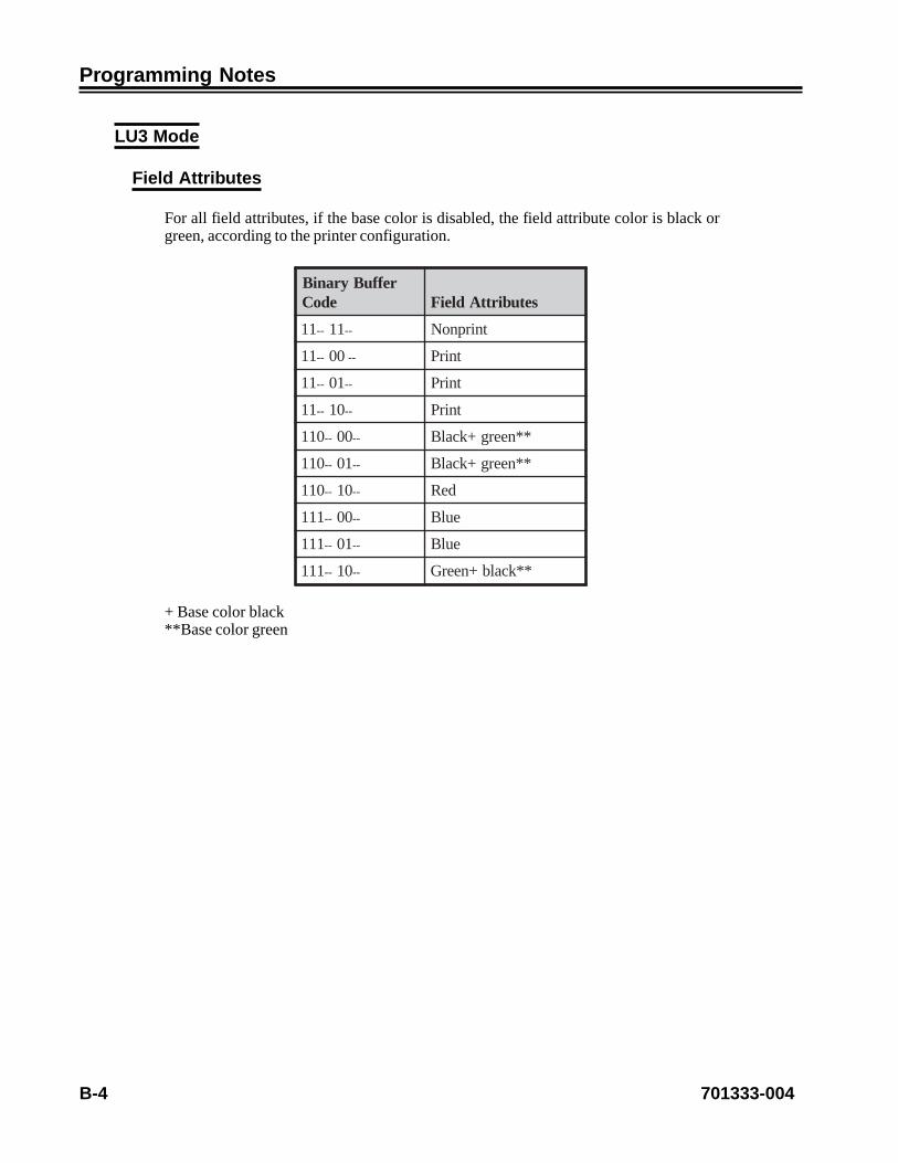
B-4 701333-004
Programming Notes
LU3 Mode
Field Attributes
For all field attributes, if the base color is disabled, the field attribute color is black orgreen, according to the printer configuration.
reffuByraniBedoC setubirttAdleiF
11 -- 11 -- tnirpnoN
11 -- 00 -- tnirP
11 -- 10 -- tnirP
11 -- 01 -- tnirP
011 -- 00 -- **neerg+kcalB
011 -- 10 -- **neerg+kcalB
011 -- 01 -- deR
111 -- 00 -- eulB
111 -- 10 -- eulB
111 -- 01 -- **kcalb+neerG
+ Base color black**Base color green

701333-004 B-5
Programming Notes
Extended Field Attributes
stiB seulaV setoN
1-0
enilrednuoN=00
enilrednuoN=10
enilrednuoN=01
retcarahcehtenilrednU=11
4-2
rolocetubirttadleifesabottluafeD=000
eulB=100
deR=010
atnegaM=110 nobbirtneccafikcalB
neerG=001
nayC=101 nobbirtneccafikcalB
wolleY=011 nobbirtneccafikcalB
enalpelpirtagnitnirpfi(rolocitluM=111)teslobmysdemmargorp
noitalumE0324/4224nikcalBedom
7-5
tesretcarahcesaB=000
tesretcarahctxeT/LPA=100
detceles2SSP=010 noitalumE0324/4224nidilavnIedom
detceles3SSP=110 noitalumE0324/4224nidilavnIedom
detceles4SSP=001 noitalumE0324/4224nidilavnIedom
detceles5SSP=101 noitalumE0324/4224nidilavnIedom
detceles6SSP=011 noitalumE0324/4224nidilavnIedom
detceles7SSP=111 noitalumE0324/4224nidilavnIedom

B-6 701333-004
Programming Notes
Character Attributes
stiB seulaV setoN
1dna0
ehtni1dna0stiBottluafeD=00etubirttadleifdednetxe
noitcaoN=10
noitcaoN=01
retcarahcehtenilrednU=11
4dna,3,2
ehtni4dna,3,2stiBottluafeD=000,noitcelesrolocrofsetubirttadleifdednetxe
eulB=100
deR=010
atnegaM=110 nobbirtneccafikcalB
neerG=001
nayC=101 nobbirtneccafikcalB
wolleY=011 nobbirtneccafikcalB
enalpelpirtagnitnirpfi(rolocitluM=111)teslobmysdemmargorp
noitalumE0324/4224nikcalBedom
7dna,6,5
ehtni7dna,6,5stiBottluafeD=000tesretcarahcrofetubirttadleifdednetxe
,noitceles
tesretcarahctxeT/LPA=100
detceles2SSP=010 noitalumE0324/4224nidilavnIedom
detceles3SSP=110 noitalumE0324/4224nidilavnIedom
detceles4SSP=001 noitalumE0324/4224nidilavnIedom
detceles5SSP=101 noitalumE0324/4224nidilavnIedom
detceles6SSP=011 noitalumE0324/4224nidilavnIedom
detceles7SSP=111 noitalumE0324/4224nidilavnIedom

701333-004 B-7
Programming Notes
Programming in IPDS Data Stream
Initialization Defaults
When the 1330 is powered on, IPDS parameters are set to their initialization defaultvalues. These values remain in effect until they are overridden by specific datastreamcommands from the host application program.
IPDS initialization default values for the 1330 are as follows.
tluafeD noitpircseD eulaV)xeH(
setoN
eulavesabstinu-L sehcni01 00
esabrepstinu-lX sehcni01rep00441lamiceD 0483
esabrepstinu-lY sehcni01rep00441lamiceD 0483
egaplacisyhpfohtdiW noitceleslenappo,eulavPPM
egaplacisyhpfohtgneL noitceleslenappo,eulavLPM
niegaplacigolfohtdiWtnetxe-Xstinu-l
stinu0441,htdiwhcni-2.31lamiceDhcnirep
04A4
niegaplacigolfohtgneLtnetxe-Ystinu-l
stinu0441,htgnelhcni-11lamiceDhcnirep
0ED3
sgalfatadderedrO sgalftxet/kcolb/egapderedronU 00
noitatneirosixa-X seerged0 0000
noitatneirosixa-Y seerged09 00D2
noitisoptxetItnerruC 0000
noitisoptxetBtnerruC enilesabepyttnoftluafeD 0A00 seriuqer1enilnognitnirptxeTeulavtnemecalpsid-Ylaitinina
.0A00fo
tnemecalpsid-Xmorftnemecalpsid-XegaplacigoL
nigiroegaplacisyhp0000
tnemecalpsid-Y morftnemecalpsid-YegaplacigoLnigiroegaplacisyhp
0000
ninigramenilnilaitinIstinu-l
0000
tnemtsujdaretcarahcretnI 0000
tnemercnienilesaB nodesab,noitceleslenappoenilffOgnittesIPL

B-8 701333-004
Programming Notes
tluafeD noitpircseD eulaV)xeH(
setoN
DItnoflacoL FF siFF=DItnoflacolnehWecneuqesenilnitsetaleht,desu
txeTteSrehtienidehsilbatsedaoLro)OTS(noitatneirO
desusi)DPL(rotpircseDegaPtnirpotrehtehwenimretedot
tfeL.tfelotthgirrothgirottfel.tluafedehtsithgirot
roloctxeT kcalB
DIegapedoC poenilffomorfnoitcelesegaugnaLlenap
ytilauqtnoF poenilffomorfnoitcelesytilauqtnirPlenap
epyttnoF IPCdnaytilauqtnirpybdenimreteDlenappoenilffomorfsnoitceles
,ytilauQgnissecorPataDroFroF.cihtoGsitnoftluafedeht
ytilauQtxeTgnissecorPataDeht,ytilauQretteLraeNdna
.reiruoCsitnoftluafed
gnildnahnoitpecxElortnoc
noitisop,sretcarahcdenifednutropeRoD.snoitpecxerehtolladna,skcehc
.noitcanoitpecxeetanretlaekattonemohotogdna,egaptnirp,etanimreT
.etats

701333-004 B-9
Programming Notes
Command Format
All 1330 commands use the following format:
Length/Command/Flag/Correlation ID (Optional)/Data
The following table shows the purpose of each field.
etyB dleiF noitpircseD
1-0 htgneL setybhtgnelgnidulcni,htgneldnammoclatoT
3-2 dnammoC epytdnammoC
4
galF 0tiBderiuqertonesnopseregdelwonkcA=0
deriuqeresnopseregdelwonkcA=11tiB
dedulcnitonDInoitalerroC=0dedulcniDInoitalerroC=1
2tiBylperegdelwonkcA=0 etelpmocsiesnopser
deriuqerylperCPO-HOXforeffubdnoceS=16-3stiB
)orezsyawla(devreseR7tiB
kcaNtnetsisreP
6-5 DInoitalerroC )NOsi1tiB,4etyBfiylnodilav(emanreifitnedI
n-7 ataD atadro/dna,sretemarap,sdnarepo,sdnammocbuscificepSdnammocnevigehtrofetairporppasasdleif
Note 1: Bit numbering follows the EBCDIC standard, with Bit 0 being the mostsignificant bit.
Note 2: If the Correlation ID field is not present (Byte 4, Bit 1 is 0), the data field startsat Byte 5 rather than at Byte 7.
Note 3: Both positive and negative values in the data fields are allowable. Negativevalues are in twos-complement form.
Note 4: Some bytes or bits in the data fields are reserved. The printer does not alwayscheck the contents of these fields. However, it is recommended that such fieldsequal the specified value (if one exists) or zero.
Note 5: The 1330 will not detect a condition where the specified command length (Bytes0-1) exceeds the actual number of bytes received. If this occurs, the printer willnot process the command until it receives the specified number of bytes.

B-10 701333-004
Programming Notes
Note 6: If the host wants to request the second buffer, the request must be the nextcommand following the request for the first buffer of an acknowledgment.However, it is not required that the host request the second buffer of anacknowledgment.
IPDS Command Codes
The IPDS function sets supported by the 1330 include the following:
• Device Control function set
• Text function set
• Image function set
• Graphics function set
• Bar Code function set
• Overlay function set
• Page Segment function set
• Loaded Font function set
Device Control Function Set Commands
The Device Control function set contains the commands used to set up the page,communicate device controls, and manage the Acknowledge protocol. The Device Controlfunction set commands are:
dnammoC edoC noitpircseD
PON 306D noitarepOoN
MTS 4E6D ledoMdnaepyTesneS
SHS 796D etatSemoHteS
KCA FF6D ylpeRegdelwonkcA
CCL F96D lortnoCypoCdaoL
PPL D66D noitisoPegaPdaoL
DPL FC6D rotpircseDegaPdaoL
PB FA6D egaPnigeB
PE FB6D egaPdnE
DNE D56D dnE
HOX F86D etatSemoHredrOetucexE
AOX 336D etatSynAredrOetucexE

701333-004 B-11
Programming Notes
Text Function Set Commands
The Text function set contains the commands and data controls for presenting textinformation on a logical page, page segment, or overlay area on a physical page. TheText function set commands are:
dnammoC edoC noitpircseD
EFL F36D ecnelaviuqEtnoFdaoL
EL D16D ecnelaviuqEdaoL
TW D26D txeTetirW
Image Function Set Commands
The Image function set contains the commands and data controls for presenting imagedata on a logical page, page segment, or overlay area on a physical page. The Imagefunction set commands are:
dnammoC edoC noitpircseD
CIW D36D lortnoCegamIetirW
IW D46D egamIetirW
DNE D56D dnE
Graphics Function Set Commands
The Graphics function set contains the commands and data controls for presenting graphicspictures on a logical page, page segment, or overlay area on a physical page. The Graphicsfunction set commands are:
dnammoC edoC noitpircseD
CIW D36D lortnoCegamIetirW
IW D46D egamIetirW
DNE D56D dnE
Graphics is a data type the 1330 uses to present line art drawings in a graphics block areaon a page. A sequence of drawing orders produces arcs, lines, fillets, character strings,markers, and other elements to define the drawing. These orders, grouped into one ormore segments, present the picture.
The controller sends a Write Graphics Control command to the printer to establish thecontrol parameters and initial drawing conditions for presenting the picture data. Thepicture segments themselves are sent to the printer as data in one or more Write Graphicscommands.

B-12 701333-004
Programming Notes
Bar Code Function Set Commands
The Bar Code function set contains the commands and controls for presenting bar codeinformation on a logical page, page segment, or overlay area on a physical page. The BarCode function set commands are:
dnammoC edoC noitpircseD
CCBW 086D lortnoCedoCraBetirW
CBW 186D edoCraBetirW
DNE D56D dnE
Overlay Function Set Commands
The Overlay function set contains the commands used to store, delete, and presentinformation in the overlay memory of the printer. These commands are independent ofany specific data types used in defining the overlay.
The overlay is contained between the BO (Begin Overlay) command and the EP (EndPage) command and cannot contain itself. Overlays can be nested – that is, overlays cancontain other overlays. The depth of the overlay nesting cannot exceed five levels.
The Overlay function set commands are:
dnammoC edoC noitpircseD
OB FD6D yalrevOnigeB
OD FE6D yalrevOeteleD
OI D76D yalrevOedulcnI
Page Segment Function Set Commands
The Page Segment function set contains the commands used to store, delete, and presentinformation in the page segment memory of the printer. These commands are independentof any specific data types defining the page segment. The Page Segment function setcommands are:
dnammoC edoC noitpircseD
SPB F56D tnemgeSegaPnigeB
SPD F66D tnemgeSegaPeteleD
SPI F76D tnemgeSegaPedulcnI

701333-004 B-13
Programming Notes
Loaded Font Function Set Commands
The Loaded Font function set contains the commands used to download and delete fontinformation from the font storage of the printer. The Loaded Font function set commandsare:
dnammoC edoC noitpircseD
SSL E16D teSlobmySdaoL
FD F46D tnoFeteleD
Using Escape Sequences in 3270 Mode
In a multiuser environment, several programs or display stations may require specialprinting formats. It is possible to vary printed output by sending 2124 escape sequencesto the 1330 in the datastream. The requirement to reset parameters from the 1330 operatorcontrol panel is therefore eliminated.
A 1330 printer escape sequence consists of an escape character and an escape code.
• The escape character alerts the 1330 to expect an escape code. This appendixprovides instructions for setting the escape character from the operator controlpanel. Check with your system manager for the correct escape character to use.
• Escape codes give the 1330 specific instructions to change a parameter, such asfont, number of lines, or characters per inch. During printing, escape codes in thedatastream take priority over parameters set from the control panel. In addition,the 1330 provides escape codes to vary character style, including italicizing, bolding,underlining, and elongation.
An escape sequence is structured as shown below.
Escape Sequence (entered with the text at the display station):
Escape Character(selected from Figure B-2)
Escape Code(selected fromFigure B-3)
>1F
Figure B-1. Escape Sequence Structure

B-14 701333-004
Programming Notes
Escape sequences can be linked to get the desired combination of print format and style.For example, the string >81>89>8C provides near letter quality at 12 characters per inch(CPI) and 3 lines per inch (LPI).
Selecting the Escape Character
The code that alerts the 1330 to expect an escape sequence is called the escape character.The escape character must be set from the 1330 Operator Control Panel keypad. Choosea character that is available on your display terminal keyboard, and that you would notuse in day-to-day printing operations.
Note: A character, once selected to be an escape character, will be nonprintable. Forthis reason, the escape character should be one that is never otherwise used.
Refer to the table in Figure B-2 to find the escape character you want to use. (Note thatsymbols in this table are for reference only.) Then enter the decimal number correspondingto this character in the printer’s memory by using Configuration Option 503, 2124 EscapeCharacter. First, however, follow the instructions under “Getting Started,” immediatelyfollowing.
Getting Started
Before you set the escape character, use Configuration Option 501, Printer EmulationMode, to enable the 1330 to support 2124-2E escape codes.
Note: For more information on the 1330 configuration procedure, refer to Chapter 4of this manual.
1. Press the Stop key, if the printer is ready.
2. Enter Menu mode by pressing the Option key.
3. Select Option 501.
4. Press the Left Arrow or Right Arrow key until 3 (2124) is displayed.
5. Press the Save key to store this choice.

701333-004 B-15
Programming Notes
800 > 930 7 070 õ 101 Ã 231 e 361 D
900 < 040 8 170 ÿ 201 Õ 331 f 461 E
010 [ 140 9 270 à 301 Y 431 g 561 F
110 ] 240 ß 370 è 401 A 531 h 661 G
210 ) 340 § 470 é 501 E 631 i 761 H
310 ( 440 # 570 ì 601 E 731 j 861 I
410 } 540 @ 670 ò 701 I 831 k 961 J
510 { 640 % 770 ù 801 O 931 l 071 K
610 PS 740 _ 870 ü 901 U 041 m 171 L
710 = 840 & 970 ç 011 Y 141 n 271 M
810 940 - 080 ä 111 C 241 o 371 N
910 ” 050 . 180 ë 211 Ä 341 p 471 O
020 / 150 , 280 ï 311 Ë 441 q 571 P
120 \ 250 : 380 ö 411 Ï 541 r 671 Q
220 | 350 + 480 ü 511 Ö 641 s 771 R
320 450 ¬ 580 â 611 Ü 741 t 871 S
420 ? 550 – 680 ê 711 Â 841 u 971 T
520 ! 650 • 780 î 811 Ê 941 v 081 U
620 $ 750 880 ô 911 Î 051 w 181 V
720 ¢ 850 ^ 980 û 021 Ô 151 x 281 W
820 £ 950 ~ 090 á 121 Û 251 y 381 X
920 ¥ 060 ¨ 190 é 221 Á 351 z 481 Y
030 stP 160 ` 290 í 321 É 451 æ 581 Z
130 ¤ 260 ´ 390 ó 421 Í 551 ø 681 Æ
230 0 360 , 490 ú 521 Ó 651 å 781 Ø
330 1 460 à 590 ñ 621 Ú 751 ç 881 Å
430 2 560 è 690 À 721 Ñ 851 ; 981 Ç
530 3 660 ì 790 È 821 a 951 091 ;
630 4 760 ò 890 Ì 921 b 061 A 191 *
*
730 5 860 ù 920 Ò 031 c 161 B
830 6 960 ã 001 Ù 131 d 261 C
'
Figure B-2. Table for Selecting Escape Character
B-16 701333-004
Programming Notes
Setting the Escape Character
To set the escape character:
1. Press the Stop key, if the printer is ready.
2. Enter Menu mode.
3. Select Option 503.
4. Press the Left Arrow or Right Arrow key until the number of the escape characteryou want is displayed. Refer to Figure B-2.
5. Press the Save key to activate this escape character, and press Stop to quit.
To display the number of the escape character, follow Steps 1 through 3.
Final Step
Finally, use Configuration Option 804, APA Print Direction, in Chapter 4 for better barcode registration.
1. Press the Stop key.
2. Enter Options mode.
3. Select Option 804.
4. Press the Left Arrow or Right Arrow key until 1 is displayed.
5. Press the Save key to store this choice. The printer will now print unidirectionally.

701333-004 B-17
Programming Notes
Selecting Escape Codes
Select escape codes from Figure B-3, and type in the required escape sequencecombinations. Always use the escape character and the code 1F at the beginning and endof a file to clear the 1330 to normal character style. Escape code 1F resets escape codes10 through 1E, and assures that italic, boldface, underlined, or elongated characters setby another operator will not affect your printed output.
Escape codes 30 through 39 are used in printing bar codes. When escape code 32 is used,the bar code type is dependent on the interface used.
Helpful Information for Using Escape Sequences
• The codes 10, lC, lD, and 1E have a toggle function. The first entry turns on thefunction, and the second entry turns it off.
• A carriage return control code should precede sequences 8C through 90. If it doesn’t,the 1330 automatically inserts its own carriage return, which may produce anundesirable printed result.
• Using proportional spacing may cause unpredictable results, because the charactersper inch (CPI) cannot be measured.
• Under LU1, escape code functions will affect print quality, CPI, LPI, and underlinein the same way as SCS control codes.
• Powering off and on the 1330 will change the escape sequence settings back to theparameter settings selected from the operator control panel.
• Changing parameters from the operator control panel while a print job usingdatastream escape sequences is in progress is not recommended. Wait until printingstops, and then retransmit the desired escape sequences.
• When you want to turn off the italic function in the middle of a line, insert an italicblank space after the last italic character in the string, before the escape sequencethat turns off the italic function. Inserting a blank allows space for the forwardslant of the last character. Without the space, the character may not be printedcompletely. It is not necessary to insert an italic blank at the end of a line.

B-18 701333-004
Programming Notes
edoC retemaraPdetceffA setoN
01 cilatiteS,retcarahccilatitsalwolloftsumecapscilatI
)LOE(enilfodnetatpecxe
C1 ecafdlobteS
D1 enilrednuteS
E1 detagnoleteS secapsretcarahcowtseipuccoretcarahchcaE
F1 lamronteS E1-01sedocffosnruT
03 sedocrabwolebdetnirptxetoN
13 sedocrabwolebdetnirptxeT
23
sretcarahC8CPUsretcarahC31CPU
sretcarahC8NAEsretcarahC31NAE
33 devaelretnI5fo2
43 lairtsudnI5fo2
53 RABADOC
63 yesselPdeifidoM ISM
73 txetdradnatS
83 yesselP
93 9fo3
08 1tnoFtceleS retcarahclamroN
18 2tnoFtceleS )QLN(ytilauqrettelraeN
28 3tnoFtceleS gnicapslanoitroporpretcarahclamroN
38 4tnoFtceleS gnicapslanoitroporpQLN
48 QLNnitnofB-RCOtceleS 7-BerugiFeeS
58 QLNnitnofA-RCOtceleS 6-BerugiFeeS
88 01=IPCteS
98 21=IPCteS
A8 51=IPCteS
B8 71=IPCteS
C8 3=IPLteS
D8 4=IPLteS
E8 6=IPLteS
F8 8=IPLteS
09 21=IPLteS
Figure B-3. Escape Codes

701333-004 B-19
Programming Notes
Using the Bar Code Feature
Bar code printing is a special feature available on the 1330. For clarity, printed bar codeswill be referred to as bar code strips.
Bar codes are printed as the result of data entered in a sequence of steps beginning withan escape character. The procedure outlined below gives the steps necessary to print barcodes.
Scanner Data
The 1330 can print most popular bar codes (see Figure B-4). Scanning devices usuallyread only one bar code type; therefore, the type of bar code printed is dependent on thescanner in use. Your scanner will also determine the height and width of the bar codestrip.
Bar Code Data
The maximum number of printable characters is dependent on the bar code type employed.Data to be printed as bar codes consists of numbers, letters, and mathematical symbols.
Readability
Bar code strips may vary in readability.
Note: You may want to test to find the most readable strip.
Density
You must know where the bar codes and standard text (optional) are to be printed. Barcodes can be printed at 10 or 12 CPI. Setting CPI from 10 to 12 reduces the size of thebar code strip and changes the position of the bar code on the page. A maximum of eightbar codes can be printed per line.
Start Print Positions
You must know how many bar codes are to be printed per page and where the firstcharacter of the bar code strip is to be printed.
Height
A standard height for bar codes should be established throughout your organization. Barcodes can be printed in 3, 4, 6, 8, and 12 lines per inch (LPI).

B-20 701333-004
Programming Notes
Standard Text
Additional or standard text can be printed between completed bar code strips. To printthis text, you must know where the first character of text is to be printed measured fromthe left margin in 0.1-inch (2.5-mm) units. It should be normal practice to run a testprinting to check alignment before loading self adhesive labels.
The text can be printed on bar code stickers. Standard text can contain data to be usedinternally, such as the title or description of an item.
Bar Code Types
Ten types of bar codes can be printed by the 1330. Figure B-4 lists these bar codes.
edoCepacsE epyTedoCraB
*23 sretcarahC8CPU
*23 sretcarahC31CPU
*23 sretcarahC8NAE
*23 sretcarahC31NAE
33 devaelretnI5fo2
43 lairtsudnI5fo2
53 RABADOC
63 )ISM(yesselPdeifidoM
83 yesselP
93 9fo3
*UPC and EAN codes are triggered by escape code 32.
Figure B-4. Bar Code Types
701333-004 B-21
Programming Notes
Using Bar Code Escape Sequences
The following formats are used to print bar codes. Number 1 includes all parameters(required and optional), and Number 2 includes only required parameters. > = escapecharacter and NL = new line (carriage return plus line feed). NL = hexadecimal 15. Thedata separator character is a semicolon.
1. Required and optional escape sequence data:
>XXYYY;bar code data;37PPP;standard text;NLNLNLNLNLNL31
2. Required escape sequence data:
>XXYYY;bar code data;NLNLNLNLNLNL30
Escape Sequence Format
1. Escape character
2. XX Bar code type
32 through 36 and 38 through 39 are valid bar code types.
3. YYY Print head position for bar codes
This parameter is measured in 0.1-inch (2.5-mm) units from the left margin. Field isone to three digits long.
4. ; Data separator character
5. Bar code data
This data is the symbols to be printed in the bar code strip.
6. ; Data separator character
Items g through k are optional.
7. 37 Standard Text command
This is a command triggering the printing of standard text between bar codes.
8. PPP Print head position for standard text
This parameter is measured in 0.1-inch (2.5-mm) units from the left margin. Field isone to three digits long.
9. ; Data separator character

B-22 701333-004
Programming Notes
10. Standard text
This is the text printed between bar code strips.
11. ; Data separator character
12. NL New line
The height of the printed bar code characters equals the number of New Linecommands multiplied by the reciprocal of the number of lines per inch.
The new line calculation formula is:
Ht = (N x 1/LPI)
where
Ht = the height of the bar code characters
N = the number of New Line commands
LPI = the line density in lines per inch
LPI can be set via an escape code, at the front panel, or using an SCS characterstring.
Figure B-5 lists common bar code heights and the corresponding number of NewLine commands required to produce them.
13. Line terminator
Either 31 or 30 must be used to end the escape sequence string. If multiple bar codesare to be printed from a single bar code escape sequence, Numbers 1 through 11must be completed with or without standard text before the NL and line terminatoris entered. Up to eight bar codes can be printed per page.
rotanimreTedoCepacsE
noitinifeD
03 srabwolebdetnirptxetelbadaernamuhoN
13 srabwolebdetnirptxetelbadaernamuhedocraB

701333-004 B-23
Programming Notes
edoCraBnithgieH
sehcnI
forebmuNeniLweN
sdnammoCIPL
3/1 1 3
3/2 2
1 3
3/11 4
3/21 5
2/1 2 4
4/3 3
1 4
4/11 5
2/11 6
2/1 3 6
3/2 4
6/5 5
1 6
2/11 9
2/1 4 8
8/5 5
4/3 6
8/7 7
1 8
2/11 21
2/1 6 21
1 21
2/11 31
2 42
Figure B-5. Calculating New Line Characters
Note: Short bar code strips demand greater accuracy of the operator during the scanningprocedure.

B-24 701333-004
Programming Notes
Calculating Checksums
The checksum is a number used to assure the accuracy of the scanning of a bar code.
EAN or UPC
If EAN or UPC bar codes are printed using 7 or 12 characters, the 1330 will calculate thechecksum digits. This number (8 or 13) will be printed below the last bar code if 31 isused as the line terminator.
Plessey
If the Plessey bar code type is used, the computer operator must compute the checksummanually and add the value to the escape sequence.
Print Optical Character Reader Parameter
The 1330 prints two machine readable character sets in addition to bar codes. These setsare OCR-A and OCR-B. Character dimensions are determined by international standardsprogrammed into the printer. All characters are printed in near letter quality font at 10 or12 CPI.
The default setting is O (OFF). To enable OCR-A, use escape sequence 85. To enableOCR-B, use escape sequence 84.
The character sets are shown in Figures B-6 and B-7. The procedure to print OCR-Acharacters from the terminal is:
1. Send the 10 CPI or 12 CPI escape sequence.
2. Send the near letter quality escape sequence.
3. Send escape sequence 85.
4. Start printing.
To print OCR-B, substitute 84 for 85 in Step 3.

701333-004 B-25
Programming Notes
Figure B-6. OCR-A Character Set

B-26 701333-004
Programming Notes
Figure B-7. OCR-B Character Set

701333-004 B-27
Programming Notes
1330 Commands in ASCII Mode
The remaining pages of this appendix list the programming commands supported by theASCII interface of the 1330 Printer in its emulation modes:
• IBM Proprinter III
• IBM Proprinter III XL
For more programming information, refer to these manuals:
• IBM Proprinter III and Proprinter III XL Guide to Operations, SA34-2065-1.
• IBM Proprinter Family Technical Reference, SC31-2587-3.
Using Proprinter Commands in ASCII Mode
The following sections of this appendix summarize the commands supported by the1330’s Proprinter emulation.
If you are using an application program (word processor, spreadsheet, or windowsprogram), specify your printer as an IBM Proprinter when you install your software.
To select enhanced text functions outside of your application program, your host computerwill need to send commands (and data) to the printer via the interface. To exercise thiscapability, you will need a working knowledge of BASIC* (or an equivalent language).For example, within BASIC an LPRINT statement can be used to send a command (orcommands) to the printer. Refer to your host computer manual or to a programmer’smanual for additional information.
*Microsoft BASIC is a trademark of Microsoft Corporation.
Print Mode Commands
The characteristics of the printed output, or print mode, are changed by the commandslisted below. The default print mode will take effect when the power is turned on or whena selected print mode is reset.
The first two tables list the available print mode commands and their functions. Eachfunction below is effective until reset with another command.
Note: Double high characters require a Forms Handler module. The standard PCcharacter set will be selected by default if the Forms Handler module is notinstalled.

B-28 701333-004
Programming Notes
noitcnuF edoC lamiceD xeH
eniLybhtdiWelbuoDteS OS 41 EO
)seniLelpitluM(htdiWelbuoDteS 1WCSE 107872 1075B1
htdiWelbuoDteseR 4CDFLFFRCTV
0WCSE
0201213111
007872
41AOCODOBO
0075B1
gnitnirPIPC21teS :CSE 8572 A3B1
gnitnirPIPC51teS mCSE 90172 D6B1
)IPC1.71(desnednoCteS IS 51 FO
IPC01otteseR 2CD 81 21
)1etoNeeS(dezisahpmEteS ECSE 9672 54B1
dezisahpmEteseR FCSE 0772 64B1
enilrednUteS 1-CSE 105472 10D2B1
enilrednUteseR 0-CSE 005472 00D2B1
tpircsrepuSteS 0SCSE 003872 0035B1
tpircsrepuSteseR TCSE 4872 45B1
tpircsbuSteS 1SCSE 103872 1035B1
tpircsbuSteseR TCSE 4872 45B1
erocsrevOteS 1_CSE 105972 10F5B1
erocsrevOteseR 0_CSE 005972 00F5B1
ekirtSelbuoDteS GCSE 1772 74B1
ekirtSelbuoDteseR HCSE 2772 84B1
pikSnoitarofrePcitamotuAlecnaC OCSE 9772 F4B1
IIIretnirporPsaretnirPtceleseD 3QCSE 301872 3015B1
LXIIIretnirporPsaretnirPtceleseD 22QCSE 221872 6115B1
2teSretcarahCtceleS 6CSE 4572 63B1
retcarahCtluafeD(1teSretcarahCtceleS)nO-rewoPnoteS
7CSE 557273B1
)2etoNeeS(gnitnirPhgiHelbuoD CSE4m3m2m1m2n1n@[
4619724m3m2m1m2n1n
O4B5B14m3m2m1m2n1n
roloCtceleS 1mrCSE 1m41172 1m27B1
Print Mode Commands

701333-004 B-29
Programming Notes
Note 1: Emphasized printing is effective only in pica pitch.
Note 2: n1n2 specifies the number of mode bytes.m1m2 must be 0.m3 controls line spacing and character height.m4 controls character width.
Double high characters require a Forms Handler module. The standard PCcharacter set will be selected by default if a Forms Handler module is not installed.
Note 3: For the m1 parameters used in Select Color, refer to “Miscellaneous Commands,”later in this chapter.
Horizontal Movement Commands
The horizontal movement of the print head is controlled by the commands listed below.
noitcnuF edoC lamiceD xeH
nruteRegairraCteS RC 31 DO
ecapskcaBteS SB 80 80
tratSedoMecapSlanoitroporP 1PCSE 100872 1005B1
ecapSlanoitroporPteseR 0PCSE 000872 4005B1
)IPC21(hctiPetilEteS :CSE 8572 A3B1
IPC51teS mCSE 90172 D6B1
*)IPC1.71(desnednoCteS IS 51 FO
IPC01otteseR 2CD 81 21
Horizontal Movement Commands
*The Set Condensed command will print at 20 CPI if you have selected 20 CPI from thefront panel (Configuration Option 10). If your front panel CPI selection is other than 20CPI (that is, 10, 12, 15, or 17.1), the Set Condensed command will print at 17.1 CPI.
Note: The horizontal print position is specified with the ESC $ command at(256n2 + n1) x 1/60 inches from the left margin.
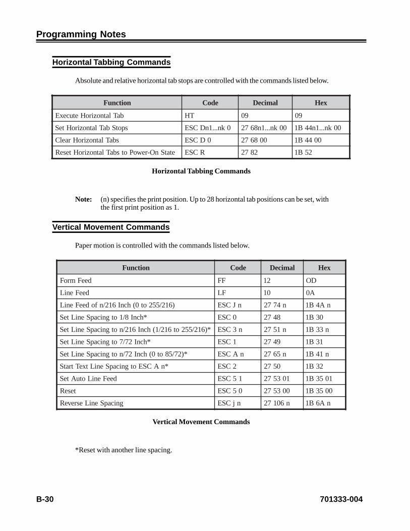
B-30 701333-004
Programming Notes
Horizontal Tabbing Commands
Absolute and relative horizontal tab stops are controlled with the commands listed below.
noitcnuF edoC lamiceD xeH
baTlatnoziroHetucexE TH 90 90
spotSbaTlatnoziroHteS 0kn...1nDCSE 00kn...1n8672 00kn...1n44B1
sbaTlatnoziroHraelC 0DCSE 008672 0044B1
etatSnO-rewoPotsbaTlatnoziroHteseR RCSE 2872 25B1
Horizontal Tabbing Commands
Note: (n) specifies the print position. Up to 28 horizontal tab positions can be set, withthe first print position as 1.
Vertical Movement Commands
Paper motion is controlled with the commands listed below.
noitcnuF edoC lamiceD xeH
deeFmroF FF 21 DO
deeFeniL FL 01 A0
)612/552ot0(hcnI612/nfodeeFeniL nJCSE n4772 nA4B1
*hcnI8/1otgnicapSeniLteS 0CSE 8472 03B1
*)612/552ot612/1(hcnI612/notgnicapSeniLteS n3CSE n1572 n33B1
*hcnI27/7otgnicapSeniLteS 1CSE 9472 13B1
*)27/58ot0(hcnI27/notgnicapSeniLteS nACSE n5672 n14B1
*nACSEotgnicapSeniLtxeTtratS 2CSE 0572 23B1
deeFeniLotuAteS 15CSE 103572 1053B1
teseR 05CSE 003572 0053B1
gnicapSeniLesreveR njCSE n60172 nA6B1
Vertical Movement Commands
*Reset with another line spacing.

701333-004 B-31
Programming Notes
Note: Line spacing in n/216 inch (base units value) will adjust the required line spacingto the nearest 1/144 inch.
Note: After receipt of a spacing command, each LF command or equivalent results inthe line feed distance specified by the spacing command.
Note: Reverse line spacing moves the paper n/144 inch in reverse and requires that aDOD module be installed. If there is no DOD module, the command is ignored.
CautionTo avoid paper jams, do not use a negative line feed command such as ESC j (n) unlessa Forms Handler module is installed. Refer to Chapter 2 for information on installing theForms Handler module.
Vertical Tabbing Commands
Vertical tab stops to control paper motion are set with the following commands.
noitcnuF edoC lamiceD xeH
mroFfopoTteS 4CSE 2572 43B1
baTlacitreVetucexE TV 11 BO
spotSbaTlacitreVteS 0kn...1nBCSE 00kn...1n6672 00kn...1n24B1
baTlacitreVteseR 0BCSERCSE
0066722872
0024B125B1
Vertical Tabbing Commands
Note: Up to 64 vertical tab locations can be set (ESC B).(nk) is an ASCII character with a binary value between 0 and 254 (ESC B).Sixty-four vertical tab locations can be set within page length.

B-32 701333-004
Programming Notes
Page Formatting Commands
These commands set the left, right, top, and bottom margins.
noitcnuF edoC lamiceD xeH
thgir=m,nigramtfel=n(snigraMlatnoziroHteS)nigram
mnXCSE mn8872mn85B1
)senil552ot1=n(noitarofrePpikS nNCSE n8772 nE4B1
)721dna1neewteBn(seniLnothtgneLegaPteS nCCSE n7672 n34B1
)22dna1neewteBn(sehcnInothtgneLegaPteS n0CCSE n007672 n0034B1
Page Formatting Commands
Note: The ESC C command clears the vertical tabs and skip.The ESC N command causes the printer to skip n lines on the current page andadvance the paper to the first printline.
morF oT
nigraMthgiR aciP 2+nigraMtfeL )nmuloC-08ehthtiw(08)nmuloC-231ehthtiw(231
etilE 3+nigraMtfeL )nmuloC-08ehthtiw(69)nmuloC-231ehthtiw(851
desnednoC 4+nigraMtfeL )nmuloC-08ehthtiw(731)nmuloC-231ehthtiw(622
nigraMtfeL aciP 0 2-nigraMthgiR
etilE 0 3-nigraMthgiR
*desnednoC 0 4-nigraMthgiR
Right and Left Margins
*At 20 CPI, the left margin is limited to 255.
Bit Image Graphics Commands
The 1330 can print characters and pictures as a collection of dots. This feature is calledbit image printing, and those commands that print bit images are called bit image graphicscommands. There are two image modes: 8-dot and 9-dot.

701333-004 B-33
Programming Notes
A bit image is structured by a collection of dots arranged in rows and columns. A collectionof eight dots sequentially arranged in a column is called a pattern byte. The smallest unitof the bit image is called a pattern element. There are two types of patterns that aredetermined by the number of dots used in an element: 8-dot and 9-dot elements.
noitcnuF edoC lamiceD xeH
egamIytisneDelgniS 2n1nKCSEkp...2p1p
2n1n5772kp...2p1p
2n1nB4B1kp...2p1p
egamIytisneDelbuoD 2n1nLCSEkp...2p1p
2n1n6772kp...2p1p
2n1nC4B1kp...2p1p
egamIdeepSelbuoDdnaytisneDelbuoD 2n1nYCSEkp...2p1p
2n1n9872kp...2p1p
2n1n95B1kp...2p1p
egamIytisneDelpurdauQ 2n1nZCSEkp...2p1p
2n1n0972kp...2p1p
2n1nA5B1kp...2p1p
Bit Image Graphics Commands
Note: (n1) and (n2) specify the number (k) of bytes of graphics data to follow, wherek = 256n2 + n1.
p1 p2...pk specifies graphics data.
In 9-Dot Image mode, the printer needs twice the number of bytes per columnof data. Therefore, the number of bytes included in the command is twice thenumber specified by (n1) and (n2).

B-34 701333-004
Programming Notes
Font Control and Download Commands
The following commands are download commands. Refer to the IBM Proprinter III andProprinter III XL Guide to Operations for information on how to design and printdownload characters.
noitcnuF edoC lamiceD xeH
)teSGClanretnI(ytilauQtfarDtceleS 0ICSE 003772 0094B1
)teSGCdaolnwoD(ytilauQtfarDtceleS 4ICSE 403772 4094B1
)tnoFtsaF()teSGClanretnI(IPC21tceleS 1ICSE 103772 1094B1
)teSGCdaolnwoD(IPC21tceleS 5ICSE 503772 5094B1
QLNtceleS 2ICSE 203772 2094B1
)teSGCQLNlanretnI(QLNtceleS GCSE 1772 74B1
)teSGCQLNlanretnI(QLNteseR HCSE 2772 84B1
)teSGCdaolnwoD(QLNtceleS 6ICSE 603772 4094B1
)teSGClanretnI(IIQLNtceleS 3ICSE 303772 3094B1
)teSGClanretnI()cilatI(IIQLNtceleS >B0<ICSE 113772 B094B1
)teSGCdaolnwoD(IIQLNtceleS 7ICSE 703772 7094B1
)teSGCdaolnwoD()etanretlA(IIQLNtceleS >F0<ICSE 513772 F094B1
sretcarahCdaolnwoDenifeD 2tc1tc=CSE0an02
11p...2p1p
2tc1tc16720an02
11p...2p1p
2tc1tcD3B10an41
11p...2p1p
Font Control and Download Commands
Note: (ct1) and (ct2) specify the number (k) of character codes to be defined, where256ct2 + ct1 = 13k + 2.
(a) refers to the attribute byte. Setting Bit 7 = 0 specifies the top 8 print wires.Setting Bit 7 = 1 specifies the bottom 8 print wires. Bits 4 through 6 specify thestarting column(s), where (0<s<7). Bits 0 through 3 specify the ending column(e), where s + 4<e<11.
(a), (0), and (p1 p2...) must be repeated for each character code being redefined.
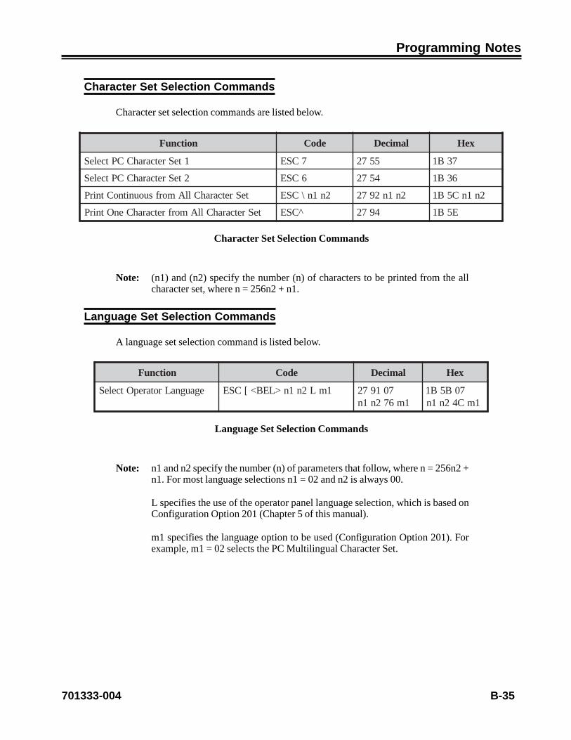
701333-004 B-35
Programming Notes
Character Set Selection Commands
Character set selection commands are listed below.
noitcnuF edoC lamiceD xeH
1teSretcarahCCPtceleS 7CSE 5572 73B1
2teSretcarahCCPtceleS 6CSE 4572 63B1
teSretcarahCllAmorfsuounitnoCtnirP 2n1n\CSE 2n1n2972 2n1nC5B1
teSretcarahCllAmorfretcarahCenOtnirP ^CSE 4972 E5B1
Character Set Selection Commands
Note: (n1) and (n2) specify the number (n) of characters to be printed from the allcharacter set, where n = 256n2 + n1.
Language Set Selection Commands
A language set selection command is listed below.
noitcnuF edoC lamiceD xeH
egaugnaLrotarepOtceleS 1mL2n1n>LEB<[CSE 7019721m672n1n
70B5B11mC42n1n
Language Set Selection Commands
Note: n1 and n2 specify the number (n) of parameters that follow, where n = 256n2 +n1. For most language selections n1 = 02 and n2 is always 00.
L specifies the use of the operator panel language selection, which is based onConfiguration Option 201 (Chapter 5 of this manual).
m1 specifies the language option to be used (Configuration Option 201). Forexample, m1 = 02 selects the PC Multilingual Character Set.

B-36 701333-004
Programming Notes
Set Initial Condition Commands
A set initial condition command is listed below.
noitcnuF edoC lamiceD xeH
noitidnoClaitinIteS 1mrapditini2n1nK[CSE2mrap
571972ditini2n1n2mrap1mrap
B4B5B11mC42n1n
Set Initial Condition Commands
n1 and n2
n1 and n2 specify the number (n) of bytes of data following and including the init byte.n1 is 1, 3, or 4, and n2 is always 0.
init
init determines which initialization should be performed. The printer supports six values:0, 1, 4, 5, 254, and 255. The definition of each init value is as follows:
00 Printer is initialized to the user-defined settings which include CPI, LPI, MPP,MPL, left margin, single or double space, and print quality. The download fontis not cleared.
01 Printer is initialized to the user-defined settings which include CPI, LPI, MPP,MPL, left margin, single or double space, and print quality. All download fontsare cleared and the language is initialized to user-defined settings (Option 201).
04 Printer is initialized to the factory default settings which include CPI, LPI, MPP,MPL, left margin, single or double space, and print quality. The download fontis not cleared, but the download selection is reset to the resident font selection.
05 Printer is initialized to the factory default settings which include CPI, LPI, MPP,MPL, left margin, single or double space, and print quality. All download fontsare cleared and the language is initialized to factory default settings.
254 When you specify a value of 254, the printer is initialized the same way as ifyou specify an init value of 01. However, the results of this initialization aresaved in storage and become the user-defined settings.
255 When you specify a value of 255, the printer is initialized the same way as ifyou specify an init value of X 05. However, the results of this initialization aresaved in storage and become the user-defined settings.
Note: init values that are not supported are treated as if they were init values of 00. Donot use init values 254 and 255 unless you are setting up the printer for the firsttime.

701333-004 B-37
Programming Notes
id
This byte specifies the printer for which the following device-dependent parameter bytesare intended. If the ID does not address your printer, the parameter bytes that follow areignored. The IDs supported by this printer are 3 (X’03') or 22 (X’16').
parm1/parm2
parm1 and parm2 are currently reserved for future development. They perform no operationin the printer.
parm2
tiB nO ffO
etybdracsiD7 etybsihterongI etybsihtssecorP
morfhctiwS6ottnofASU
tnoflaugnilitluM
tnoflaugnilitlumesUtnofASUesU
lanoitceridiB5)IPC01(QLN
lanoitceridinU lanoitceridiB)ylnoIPC01(
devreseR4
QLNtceleS3 tnofQLNstceleSyekQLN .tnofIIQLNstceleSyekQLN
elbanedeefmroF2 tsohmorfdeefmroferongImroffopottasiretnirpnehw
deefmrofronoH
htgneleniL1 repaphcni-0.8 repaphcni-6.31
devreseR0
Miscellaneous Commands
Miscellaneous commands are listed below.
noitcnuF edoC lamiceD xeH
lleB LEB 7 70
lecnaC NAC 42 81
gnitnirPlanoitceridinU 1UCSE 105872 1055B1
teseR 0UCSE 005872 0055B1
*roloCtceleS 1mrCSE 1m41172 1m27B1
Miscellaneous Commands

B-38 701333-004
Programming Notes
*For Select Color, m1 has the following values:
1mfoeulaV nobbiRroloC-4 nobbiRevitcartbuS
0 kcalB )tluafed(kcalB
1 kcalB atnegaM
2 kcalB nayC
3 eulB eulB
4 kcalB wolleY
5 deR deR
6 neerG neerG
Parameters for Select Color
If a monochrome ribbon is installed, the system will accept any parameter choice, butthe printing will be monochrome.
Using TI-810 Command Functions in ASCII Mode
The commands listed in this section are operational when the printer is in TI-810emulation.
lobmyS eulaVxeH noitpircseD
LUN 00TVteSehtetanimretotdesusilluN
sgnirts)DCSE(THteSdna)BCSE(
LEB 70 peebelgnisarofmralaehtdnuoS
SB 80 ecapskcaB
TH 90 batlatnoziroH
FL A0 deefeniL
TV B0 batlacitreV
FF C0 deefmroF
RC D0 nruteregairraC
1CD 11 retnirptceleS
2CD 21 enilotbaT
3CD 31 retnirptceleseD
4CD 41 sserddaotbaT
CSE B1 epacsE

701333-004 B-39
Programming Notes
Escape Command Strings
Format: <ESC><Command String>
edoCdnammoC eulaVxeHforebmuNsretemaraP
snoitpircseD
1 13 n tesbatlacitreV
2 23 1 teshtgnelmroF
3 33 n tesbatlatnoziroH
4 43 0 IPL6oT
5 53 0 IPL8oT
6 63 0 IPC01oT
7 73 0 IPC1.71oT
: A3 1 PPMteS
; B3 0 PPMtluafederotseR
m D6 0 IPC51oT
r 27 1 *roloctceleS
*For Select Color parameters, refer to “Miscellaneous Commands,” above.
The 1330 does not support the Denmark/Norway, United Kingdom, Germany, andSweden/Finland languages under TI-810 emulation.
The vertical format functions such as recall, store (<ESC>9, <ESC>8), and the deletecommand, are not available.

B-40 701333-004
Programming Notes
Using Escape Sequences with ANSI Bar Codes
ANSI bar code processing on the 1330 in ASCII mode is based on ANSI version X3.64-1979. The ANSI bar code is made up of three programming elements (or commands) asfollows:
1. Set Attributes – The set attributes command tells the printer what type of bar code toproduce, determines the height of the bar code, and turns the human readable indicatoron or off.
Command Format: <ESC>[<BC Type>;<BC Height>;<HRI>;}
where:
<ESC> = HEX <1B> or Decimal <27>[ = HEX <5B> or Decimal <91><BC Type> = 0 – 2 of 5 Interleaved
4 – Code 3 of 95 – EAN-86 – EAN-1313 – UPC-A14 – UPC-E (not supported)
; = HEX <3B> or Decimal <59><BC Height> = n/12 inches; = HEX <3B> or Decimal <59><HRI> = 0 Turn Human Readable Code OFF
1 Turn Human Readable Code ON; = HEX <3B> or Decimal <59>} = HEX <7D> or Decimal <125>
2. Activate Bar Code – The activate bar code command starts the printer processingthe following data as bar code characters.
Command Format: <ESC>[3t where:
<ESC> = HEX <1B> or Decimal <27>[ = HEX <5B> or Decimal <91>3 = HEX <33> or Decimal <51>t HEX <74> or Decimal <116>
3. Deactivate Bar Code – The deactivate bar code command tells the printer to stopprocessing bar code data.
Command Format: <ESC>[0t where:
<ESC> = HEX <1B> or Decimal <27>[ = HEX <5B> or Decimal <91>3 = HEX <33> or Decimal <51>t HEX <74> or Decimal <116>

701333-004 B-41
Programming Notes
Bar code data must follow the specifications of the bar code type selected. Spaces andcommas are processed as delimiters, not as bar code characters. As per the ANSI X3.64-1979 documentation, all bar codes will be preceded and followed by 1/4 inch of whitespace.
The delimiters (space and comma) are processed as follows:
Space: A space will position the print head one character position to the right of thecurrent head position, based on the current CPI selected. If the space occursas a break in the bar code datastream, an additional 1/2 inch of space isadded to the spacing of the accumulated spaces. (For example, at 10 CPI,ten spaces will position the print head one inch to the right of its currentposition. If the ten spaces are used as a break between bar codes, the printhead will position 1.5 inches to the right of its current position.)
Comma: A comma will cause a break in the bar code data. The break will cause theprint head to be positioned 1/2 inch to the right of its current position.Consecutive commas embedded in a bar code datastream will be treated asone break (or as if only one comma were encountered in the bar codedatastream).
The bar code height determines the number of linefeeds that are required to process thebar code printout. Therefore, the number of linefeeds that follows the ANSI escape codeis crucial for the entire bar code to be printed. If the bar code height is one inch, then at6 LPI it will take six linefeeds to process the bar code printout. The number of linefeedsrequired is determined by the expression LF = n/12 (LPI) without human readable andplus one or two linefeeds with human readable, where n equals the bar code’s heightparameter.
Example: Printing a “Code 3 of 9” bar code 1/2 inch high without human readablecode using the data “3 of 9.”
<ESC>[4;6;0;}<ESC>[3t 3 of 9 <ESC> [0t<CR><LF><LF><LF>
Text data may be processed with the ANSI bar code data. Text data that is contained onthe same line as the bar code commands will be processed as follows:
Leading text data will be processed from the left margin as normal. The bar code willstart 1/4 inch from the last text character processed in the leading text data. (This includesspacing as text data.) Trailing text that follows the bar code commands will start 1/4 inchafter the last bar code character processed. Any additional lines of text data will be treatedas normal text printing along with the bar code.
Note: All ANSI bar codes will start the top of the bar code on the same line that theActivate Bar Code command is found.
CautionText that occurs adjacent to the bar code, but is not on the same line as the bar codecommand, can overprint the bar code if spacing is not provided for positioning databeyond the bar code.

B-42 701333-004
Programming Notes
Example: Printing a “Code 3 of 9” bar code 1/2 inch high without human readablecode using the data “3 of 9” as the bar code with three lines of text adjacentto the bar code. One line of text will be on the same line as the bar codecommand and two lines will follow that complete the processing of the barcode printout.
Data before <ESC>[4;6;0;}<ESC>[3t 3 of 9 <ESC>[0t Data after <CR> <LF>Line 2<CR><LF>Line 3<CR><LF>

701333-004 C-1
Appendix C. Character Sets
The following tables show the character sets used by the 1330 in ASCII mode. Thecharacters in each of these sets can be printed in Draft, DP Text, and NLQ.
PC CHARACTER SET 1
(Available with Proprinter emulation)
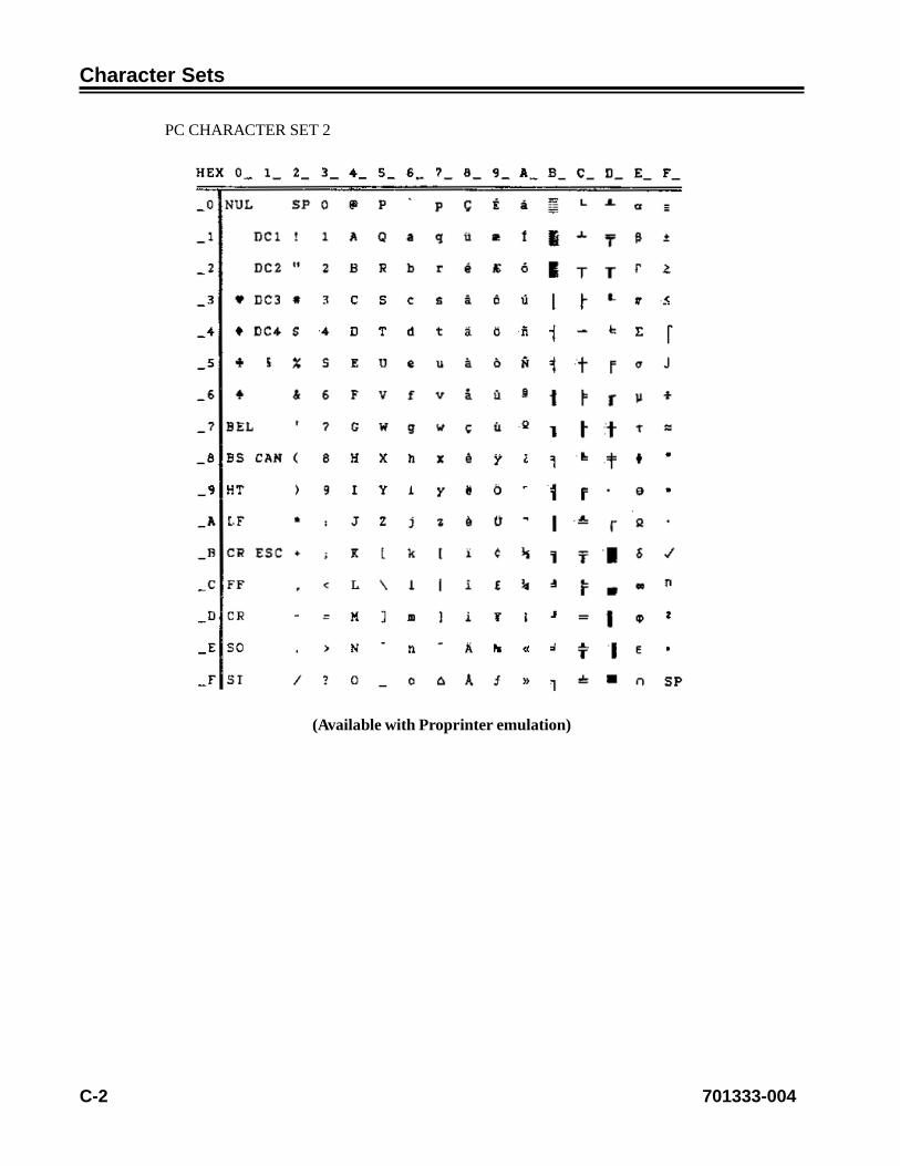
C-2 701333-004
Character Sets
PC CHARACTER SET 2
(Available with Proprinter emulation)

701333-004 C-3
Character Sets
PC ALL CHARACTER SET
(Available with Proprinter emulation)

C-4 701333-004
Character Sets
PC MULTILINGUAL CHARACTER SET
(Available with Proprinter emulation)

701333-004 C-5
Character Sets
TI-810 Character Set(Available with TI-810 Emulation)
retcarahC eulaVxeH eulaVlamiceD
)ecaps( 02 23
! 12 33
“ 22 43
# 32 53
$ 42 63
% 52 73
& 62 83
‘ 72 93
( 82 04
) 92 14
* A2 24
+ B2 34
, C2 44
- D2 54
. E2 64
/ F2 74
0 03 84
1 13 94
2 23 05
3 33 15
4 43 25
5 53 35
6 63 45
7 73 55
8 83 65
9 93 75
: A3 85
; B3 95

C-6 701333-004
Character Sets
retcarahC eulaVxeH eulaVlamiceD
X 85 88
Y 95 98
Z A5 09
[ B5 19
\ C5 29
] D5 39
^ E5 49
_ F5 59
‘ 06 69
a 16 79
b 26 89
c 36 99
d 46 001
e 56 101
f 66 201
g 76 301
h 86 401
i 96 501
j A6 601
k B6 701
Note: Using Configuration Option 201, Language, choice 3, ASCII - EBCDIC, replacesthe three ASCII characters [ ] ̂ (hex values 5B, 5D, 5E) with the three EBCDICcharacters ¢ | ¬ respectively. Refer to Chapter 5 of this manual.
Note: This table gives both the hexadecimal and decimal value of the character codes.

701333-004 D-1
Appendix D. Consumables
The tables below provide a list of part numbers for ribbons and print heads used bythe 1330.
Ribbons
traPrebmuN
noitpircseD efiLdetamitsE
100-263559 gnitfihsnon,kcalB noillim22
200-078559 yramirproloc-4 kcartrepnoillim22
Print Heads
traPrebmuN
noitpircseDdetamitsE
efiL
100-765359 tnemecalperdaehtnirperiw-81)20X-0331(tik
noillim003

701333-004 E-1
Appendix E. CharacterCount Record
The form below provides a convenient place to record the printer’s character count. Thecharacter count should be recorded each time the print head is replaced. See Chapter 4for instructions on getting the character count. See Chapter 7 for print head replacementinstructions.
Style Date Character Count
First print headreplacement ______ _______ _______________
Second print headreplacement ______ _______ _______________
Third print headreplacement ______ _______ _______________

701333-004 Index-1
410 – Full Form Feed Eject, 4-21411 – Paper Eject Adjustment, 4-21412 – Horizontal Offset, 4-22413 – Horizontal Registration, 4-22414 – Paper Jam Sensor Enable, 4-22415 – Paper Out Sensor Enable, 4-22416 – Paper Skew Sensor Enable, 4-23418 – DOD Load Adjust, 4-23419 – DID Load Adjust, 4-23420 – Stop Mode Timeout (TO), 4-24422 – Start Mode After Eject, 4-24423 – Report Intervention, 4-25501 – Printer Emulation Mode, 4-25502 – Buffer Size, 4-26503 – 2124 Escape Character, 4-26504 – Early Print Complete, 4-26601 – Interface, 4-27602 – Idle Timeout, 4-27701 – Print Configuration, 4-28702 – Quick Reference, 4-31703 – Set Factory Defaults, 4-31704 – POR Custom Set, 4-31705 – Save Custom Set, 4-32706 – Recall Custom Set, 4-32707 – Display Character Count, 4-32708 – PA1, 4-33709 – PA2, 4-33710 – Buffer Reprint, 4-33801 – Programmed Symbols, 4-33804 – APA Print Direction, 4-34901 – Serial Number, 4-34902 – Device Specification Information, 4-34
3270 Configuration options2124 Escape Character, 4-26Alarm on Error, 4-18APA Print Direction, 4-34Attribute Selectable Highlighting, 4-16Auto Eject, 4-21Base Color, 4-16Bold Print Enable, 4-10Buffer Reprint, 4-33Buffer Size, 4-26Carriage Return (CR) at MPP + 1, 4-13Characters per Inch, 4-6Device Specification Information, 4-34Display Character Count, 4-32Display Language, 4-9Dotted Zero, 4-12Early Print Complete, 4-26
Index
Symbols
100 Page Format (3270), 4-5100 Page Format (ASCII), 5-5200 Font & Print Quality (3270), 4-8200 Font & Print Quality (ASCII), 5-72124 Escape Character option (3270), 4-26300 Compatibility (3270), 4-13300 Compatibility (ASCII), 5-103270 Configuration option numbers
101 – Left Margin, 4-5102 – Characters per Inch (CPI), 4-6103 – Lines per Inch (LPI), 4-6104 – Maximum Print Position (MPP), 4-7105 – Form Length, 4-7106 – Line Spacing, 4-7107 – Force Set Media Size, 4-8201 – Language, 4-8202 – Display Language, 4-9203 – Mono/Dual Case, 4-10204 – Bold Print Enable, 4-10205 – Two-Pass Print Direction, 4-10206 – Print Quality, 4-11207 – Host Fast Draft, 4-11208 – Text Orientation, 4-11209 – Dotted Zero, 4-12210 – Graphics Density, 4-12301 – Carriage Return (CR) at MPP + 1, 4-13302 – New Line (NL) at MPP + 1, 4-13303 – Null Suppression, 4-13304 – Form Feed (FF), 4-14305 – Form Feed with Auto New Line at Print
End, 4-14306 – Midline Form Feed (FF), 4-14307 – Form Feed (FF) Printed with a Space, 4-15308 – Formatted Print, 4-15309 – Bar Code Control, 4-15310 – Base Color, 4-16311 – Attribute Selectable Highlighting, 4-16312 – Ignore SCS Commands, 4-17401 – Operator Format, 4-17402 – Key Alarm, 4-18403 – Alarm on Error, 4-18404 – Print Head Style, 4-18405 – Print Head Column Spacing, 4-19406 – Ribbon Type Override, 4-19407 – Ribbon Track Select Adjustment, 4-20408 – Module Type Override, 4-20409 – Auto Eject, 4-21

Index-2 701333-004
Index
Force Set Media Size, 4-8Form Feed (FF), 4-14Form Feed Printed with a Space, 4-15Form Feed with Auto New Line at Print End, 4-14Form Length, 4-7Formatted Print, 4-15Full Form Feed Eject, 4-21Graphics Density, 4-12Horizontal Offset, 4-22Horizontal Registration, 4-22Host Fast Draft, 4-11Idle Timeout, 4-27Interface, 4-27Key Alarm, 4-18Language, 4-8Left Margin, 4-5Line Spacing, 4-7Lines per Inch, 4-6Maximum Print Position, 4-7Midline Form Feed (FF), 4-14Module Type Override, 4-20Mono/Dual Case, 4-10New Line (NL) at MPP + 1, 4-13Null Suppression, 4-13Operator Format, 4-17PA1, 4-33PA2, 4-33Paper Eject Adjustment, 4-21Paper Jam Sensor Enable, 4-22Paper Out Sensor Enable, 4-22Paper Skew Sensor Enable, 4-23POR Custom Set, 4-31Print Configuration, 4-28Print Head Column Spacing, 4-19Print Head Style, 4-18Print Quality, 4-11Printer Emulation Mode, 4-25Programmed Symbols, 4-33Quick Reference, 4-31Recall Custom Set, 4-32Report Intervention, 4-25Ribbon Track Select Adjustment, 4-20Ribbon Type Override, 4-19Save Custom Set, 4-32Serial Number, 4-34Set Factory Defaults, 4-31Start Mode After Eject, 4-24Stop Mode Timeout, 4-24Text Orientation, 4-11Two-Pass Print Direction, 4-10
400 Printer Setup (3270), 4-17400 Printer Setup (ASCII), 5-14500 Communication (3270), 4-25
500 Communication (ASCII), 5-22600 Attachment (3270), 4-27600 Attachment (ASCII), 5-26700 Extended Keypad (3270), 4-28700 Extended Keypad (ASCII), 5-27800 Program Symbol (3270), 4-33
A
Adjusting the Top of Form Position, 6-3Alarm on Error option (3270), 4-18Alarm on Error option (ASCII), 5-15All Points Addressability, 1-5APA Print Direction option (3270), 4-34ASCII Configuration option numbers
101 – Left Margin, 5-5102 – Characters per Inch (CPI), 5-5103 – Lines per Inch (LPI), 5-6104 – Maximum Print Position (MPP), 5-6105 – Form Length, 5-7106 – Line Spacing, 5-7201 – Language, 5-7202 – Display Language, 5-8203 – Mono/Dual Case, 5-9204 – Bold Print Enable, 5-9205 – Two-Pass Print Direction, 5-9206 – Print Quality, 5-10301 – Vertical Tab Setting, 5-10302 – Define Horizontal Tab (810), 5-11303 – Carriage Return Definition, 5-11304 – Line Feed Definition, 5-11305 – Automatic Perforation Skip, 5-12306 – Ignore Sign, 5-12307 – Bit Graphics, 5-12308 – BC Space CHR, 5-13309 – Bar Code Control, 5-13401 – Save Operator Format, 5-14402 – Key Alarm, 5-14403 – Alarm on Error, 5-15404 – Print Head Style, 5-15405 – Print Head Column Spacing, 5-15406 – Ribbon Type Override, 5-16407 – Ribbon Track Select Adjustment, 5-16408 – Module Type Override, 5-17409 – Auto Eject, 5-17410 – Auto Return, 5-17411 – Paper Eject Adjustment, 5-18412 – Horizontal Offset, 5-18413 – Horizontal Registration, 5-19414 – Paper Jam Sensor Enable, 5-19415 – Paper Out Sensor Enable, 5-19416 – Paper Skew Sensor Enable, 5-20418 – DOD Load Adjust, 5-20

701333-004 Index-3
Index
419 – DID Load Adjust, 5-20421 – Operator Panel Adjust, 5-21422 – Start Mode After Eject, 5-21423 – Report Intervention, 5-21501 – Printer Emulation Mode, 5-22502 – Buffer Size, 5-22503 – DC1/DC3 Recognition, 5-22504 – Baud Rate, 5-23505 – Parity, 5-23506 – Data Bits, 5-24507 – Stop Bits, 5-24508 – Modem Control, 5-24509 – Handshaking, 5-25510 – Reserved, 5-25511 – RS-422 Polarity, 5-25601 – Interface, 5-26602 – Idle Timeout, 5-26603 – Interface Type, 5-27701 – Print Configuration, 5-27702 – Quick Reference, 5-30703 – Set Factory Defaults, 5-30704 – POR Custom Set, 5-30705 – Save Custom Set, 5-31706 – Recall Custom Set, 5-31707 – Display Character Count, 5-31
ASCII Configuration optionsAlarm on Error, 5-15Auto Eject, 5-17Auto Return, 5-17Automatic Perforation Skip, 5-12Bar Code Control, 5-13Baud Rate, 5-23BC Space CHR, 5-13Bit Graphics, 5-12Bold Print Enable, 5-9Buffer Size, 5-22Carriage Return Definition, 5-11Characters per Inch, 5-5Data Bits, 5-24DC1/DC3 Recognition, 5-22Define Horizontal Tab (810), 5-11DID Load Adjust, 5-20Display Character Count, 5-31Display Language, 5-8DOD Load Adjust, 5-20Form Length, 5-7Handshaking, 5-25Horizontal Offset, 5-18Horizontal Registration, 5-19Idle Timeout, 5-26Ignore Sign, 5-12Interface, 5-26Interface Type, 5-27
Key Alarm, 5-14Language, 5-7Left Margin, 5-5Line Feed Definition, 5-11Line Spacing, 5-7Lines per Inch, 5-6Maximum Print Position, 5-6Modem Control, 5-24Module Type Override, 5-17Mono/Dual Case, 5-9Operator Panel Adjust, 5-21Paper Eject Adjustment, 5-18Paper Jam Sensor Enable, 5-19Paper Out Sensor Enable, 5-19Paper Skew Sensor Enable, 5-20Parity, 5-23POR Custom Set, 5-30Print Configuration, 5-27Print Head Column Spacing, 5-15Print Head Style, 5-15Print Quality, 5-10Printer Emulation Mode, 5-22Recall Custom Set, 5-31Report Intervention, 5-21Reserved, 5-25Ribbon Track Select Adjustment, 5-16Ribbon Type Override, 5-16RS-422 Polarity, 5-25Save Custom Set, 5-31Save Operator Format, 5-14Set Factory Defaults, 5-30Start Mode After Eject, 5-21Stop Bits, 5-24Two-Pass Print Direction, 5-9Vertical Tab Setting, 5-10
Attribute Selectable Highlighting option (3270), 4-16Auto Eject option (3270), 4-21Auto Eject option (ASCII), 5-17Auto Return option (ASCII), 5-17Automatic Perforation Skip option (ASCII), 5-12
B
Bar Code Control option (ASCII), 5-13Base Color option (3270), 4-16Baud Rate option (ASCII), 5-23BC Space CHR option (ASCII), 5-13Bit Graphics option (ASCII), 5-12Bold Print Enable option (3270), 4-10Bold Print Enable option (ASCII), 5-9Buffer Reprint option (3270), 4-33Buffer Size option (3270), 4-26Buffer Size option (ASCII), 5-22

Index-4 701333-004
Index
C
CablesConnecting a Parallel Cable, 2-10Connecting a Serial Cable, 2-10Connecting the Coax Cable, 2-9Connecting the Power Cable, 2-8
Cancel Print key, 3-5Carriage Return (CR) at MPP + 1, 4-13Carriage Return Definition option (ASCII), 5-11Character Codes (3270), 1-3Character Codes (ASCII), 1-3Character Width, 7-6Characters per Inch option (3270), 4-6Characters per Inch option (ASCII), 5-5Cleaning, 7-1Configuration Options, 4-5Connecting a Parallel Cable, 2-10Connecting a Serial Cable, 2-10Contrast key, 3-5
D
Data Bits option (ASCII), 5-24DC1/DC3 Recognition option (ASCII), 5-22Define Horizontal Tab (810) option (ASCII), 5-11Device Specification Information option (3270), 4-34DID Load Adjust, 4-23, 5-20Display Character Count option (3270), 4-32Display Character Count option (ASCII), 5-31Display Language option (3270), 4-9Display Language option (ASCII), 5-8Document Insertion Device (DID), 1-6Document on Demand (DOD), 1-6DOD Load Adjust, 4-23, 5-20Dotted Zero option (3270), 4-12Down Arrow key, 3-4
E
Early Print Complete option (3270), 4-26Emulation (3270), 1-2Emulation (ASCII), 1-3Error Message Chart, A-1Errors
General, 8-1Intervention required, 8-1Unusual, 8-1
Escape CharactersSelecting, B-14
F
Force Set Media Size option (3270), 4-8Form Feed (FF) option (3270), 4-14
Form Feed key, 3-4Form Feed Printed with a Space option (3270), 4-15Form Feed with Auto New Line at Print End option, 4-14Form Length option (3270), 4-7Form Length option (ASCII), 5-7Formatted Print option (3270), 4-15Forms Specifications, 2-11Full Form Feed Eject option (3270), 4-21
G
General errors, 8-2Graphics Density option (3270), 4-12
H
Handshaking option (ASCII), 5-25Horizontal Offset option (3270), 4-22Horizontal Offset option (ASCII), 5-18Horizontal Registration option (3270), 4-22Horizontal Registration option (ASCII), 5-19Host Fast Draft option (3270), 4-11
I
Idle Timeout option (3270), 4-27Idle Timeout option (ASCII), 5-26Ignore Sign option (ASCII), 5-12Installing Forms
Continuous Forms Module, 2-17DID Option, 2-23DOD Option, 2-21Forms Handler Module, 2-21
Installing the ribbonNonshifting, 2-7Shifting, 2-4
Installing the Ribbon Cartridge, 2-4Intelligent Printer Data Stream (IPDS), 1-5Interface option (3270), 4-27Interface option (ASCII), 5-26Interface Type option (ASCII), 5-27
K
Key Alarm option (3270), 4-18Key Alarm option (ASCII), 5-14Keys
Cancel Print key, 3-5Contrast key, 3-5Down Arrow key, 3-4Form Feed key, 3-4Line Space key, 3-4Option key, 3-5Save key, 3-5

701333-004 Index-5
Index
Setup key, 3-5Start key, 3-3Stop key, 3-3Top of Form key, 3-4Up Arrow key, 3-4
L
Language option (3270), 4-8Language option (ASCII), 5-7Left Margin option (3270), 4-5Left Margin option (ASCII), 5-5Line Feed Definition option (ASCII), 5-11Line Space key, 3-4Line Spacing option (3270), 4-7Line Spacing option (ASCII), 5-7Lines per Inch option (3270), 4-6Lines per Inch option (ASCII), 5-6
M
Maximum Print Position option (3270), 4-7Maximum Print Position option (ASCII), 5-6Midline Form Feed option (3270), 4-14Modem Control option (ASCII), 5-24Module Type Override option (3270), 4-20Module Type Override option (ASCII), 5-17Mono/Dual Case option (3270), 4-10Mono/Dual Case option (ASCII), 5-9
N
New Line (NL) at MPP + 1 option (3270), 4-13Nonshifting Ribbon, 2-7Null Suppression option (3270), 4-13
O
Operator Control Panel, 3-1Operator Format option (3270), 4-17Operator Panel Adjust option (ASCII), 5-21Option key, 3-5
P
PA1 option (3270), 4-33PA2 option (3270), 4-33Paper Eject Adjustment option (3270), 4-21Paper Eject Adjustment option (ASCII), 5-18Paper Jam Sensor Enable option (3270), 4-22Paper Jam Sensor Enable option (ASCII), 5-19Paper Out Sensor Enable option (3270), 4-22Paper Out Sensor Enable option (ASCII), 5-19Paper Skew Sensor Enable option (3270), 4-23Paper Skew Sensor Enable option (ASCII), 5-20Parallel Cable, 2-10
Parity option (ASCII), 5-23Part Numbers
Nonshifting ribbon, 2-4print head, 7-2Shifting ribbon, 2-4
POR Custom Set option (3270), 4-31POR Custom Set option (ASCII), 5-30Power Cable Requirements, 2-8Print Buffer
Reprinting, 6-4Print Configuration option (3270), 4-28Print Configuration option (ASCII), 5-27Print Head Column Spacing option (3270), 4-19Print Head Column Spacing option (ASCII), 5-15Print Head Style option (3270), 4-18Print Head Style option (ASCII), 5-15Print Quality option (3270), 4-11Print Quality option (ASCII), 5-10Print Registration, 7-5Printer Emulation Mode option (3270), 4-25Printer Emulation Mode option (ASCII), 5-22Printing the Setup Line, 6-2Programmed Symbols option (3270), 4-33Programming commands
Proprinter Commands, B-27TI-810 Commands, B-38
Q
Quick Reference option (3270), 4-31Quick Reference option (ASCII), 5-30
R
Recall Custom Set option (3270), 4-32Recall Custom Set option (ASCII), 5-31Replacing the Print Head, 7-1Report Intervention option (3270), 4-25Report Intervention option (ASCII), 5-21Reprinting the Print Buffer, 6-4Reserved option (ASCII), 5-25Ribbon Track Select Adjustment option (3270), 4-20Ribbon Track Select Adjustment option (ASCII), 5-16Ribbon Type Override option (3270), 4-19Ribbon Type Override option (ASCII), 5-16Ribbons
Installing a Nonshifting Ribbon, 2-7Installing a Shifting Ribbon, 2-4Ordering, 2-4Replacement, 7-1
RS-422 Polarity option (ASCII), 5-25

Index-6 701333-004
Index
S
Save Custom Set option (3270), 4-32Save Custom Set option (ASCII), 5-31Save key, 3-5Save Operator Format option (ASCII), 5-14SCS Mode
Halting a Print Operation, 6-5Requesting a Host Application Program, 6-5
Serial Cable, 2-10Serial Number option (3270), 4-34Set Factory Defaults option (3270), 4-31Set Factory Defaults option (ASCII), 5-30Setup key, 3-5Setup Line
Printing, 6-2Shifting Ribbon, 2-4Start key, 3-3Start Mode After Eject option (3270), 4-24Start Mode After Eject option (ASCII), 5-21Status Display, 3-1Status Message Chart, A-1Stop Bits option (ASCII), 5-24Stop key, 3-3Stop Mode Timeout option (3270), 4-24
T
Text Orientation option (3270), 4-11Top of Form
Adjusting, 6-3Top of Form key, 3-4Two-Pass Print Direction option (3270), 4-10Two-Pass Print Direction option (ASCII), 5-9
U
Unpacking the Printer, 2-1Unusual Errors, 8-2Up Arrow key, 3-4
V
Ventilation, 7-1Vertical Tab Setting option (ASCII), 5-10