13524 - xl650 man. v 6 -...
TRANSCRIPT
illonrecision
Products, Inc.Manufacturers of The World's FinestLoading Equipment
XL 650Instruction Manual
Version 6.1

Dillon Precision Products, Inc.8009 E. Dillon’s WayScottsdale, AZ 85260
(480) 948-8009FAX (480) 998-2786
Web Site: www.dillonprecision.comE-mail: [email protected]
Technical Support & Customer Service(800) 223-4570
On the cover…The XL 650 is pictured with optional accessories:Strong Mount (550/650) #22051Strong Mount (650 only) #22052Aluminum Roller Handle #17950Low Powder Sensor #16306Bullet Tray #22214Powdercheck System #21044Electric Casefeeder (four sizes available)Other accessories available for the XL 650 include:Video Instruction Manual #15064Machine Cover #10443Maintenance Kit & Spare Parts Kit #97017The Blue Press, Dillon’s monthly catalog, has a complete listing of accessories available for all machines.
Part #13524 Spot Manuals XL 650 Folder XL 650 Man. 6.1 9/01 WJC

Page #
Mandatory Safety Measures 5Getting Started 61. Unboxing your machine 62. Mounting your XL 650 73. Initial Set-Up 7
A. Installation of Handle 7B. Installation of the Spent Primer Cup and Cartridge Bin 8C. Installation of the Casefeed Post 8D. Installation of the Casefeed Tube Bracket 8E. Installation of the Optional Casefeeder 9
4. Toolhead Overview 11Lubricating Brass 11Pistol Section – Toolhead Set Up 12
A. Station One – Installation of the Sizing/Decapping Die 12B. Station One – The Decapping assembly 12C. Station Two – Installation of the Powder Measure Assembly 12D. Station Two – About Powder Bars 13E. Station Two – Adjustment of the Powder Die/Powder Funnel 14F. Station Two – Installation of the Failsafe Rod Assembly 15G. Station Three – Installation of the Powder Check System 16H. Station Four – General Information on Bullet Seating 17I. Station Four – Seating Stems 18J. Station Four – Installation and Adjustment of the Seating Die 18K. Station Five – Installation and Adjustment of the Crimp Die 18
Rifle Section – Toolhead Set Up 20A. Station One – About the Case Gage 20B. How to Use the Case Gage 20C. Station One – Installation of the Sizing/Decapping Die 21D. Station One – The Decapping assembly 22E. Station Two – Installation of the Powder Measure Assembly 22F. Station Two – About Powder Bars 23G. Station Two – Adjustment of the Powder Die/Powder Funnel 23H. Station Two – Installation of the Failsafe Rod Assembly 25I. Station Three – Installation of the Powder Check System 25J. Station Four – How to Determine the Proper Seating Depth 26K. Station Four – Seating Stems 27L. Station Four – Installation and Adjustment of the Seating Die 27M. Station Five – Installation and Adjustment of the Crimp Die 28
Final Assembly 291. The Primer Magazine 292. Installation of the Primer Early Warning System 293. Installation of the Locator Buttons 30
Loading Components Section1. Primer System Overview (how it works) 302. Powder Bar Adjustment 303. Powder Check System Adjustment 31
A. Installation and Adjustment of the Powder Check Rods 31B. Powder Check System demonstration 32
4. Filling the Primer System 32
Station Orientation and Loading Funtions 34Caliber Conversion Section 35-42Trouble Shooting 43-45Caliber Conversion Chart 46-48Schematics 49-58
Table of Contents
Reloading small arms ammuni-tion involves the use of highlyexplosive primers and powder.Handling these materials is inher-ently dangerous. You should rec-ognize this danger and take certainminimum precautions to lessenyour exposure to injury.
Never operate the machinewithout ear and eye protection on.Call our customer service depart-ment at (800) 223-4570 for informa-tion on the wide variety of shoot-ing/safety glasses and hearingprotection that Dillon has to offer.• PAY ATTENTION: Load onlywhen you can give your com-plete attention to the loadingprocess. Don’t watch televisionor try to carry on a conversationand load at the same time. Watchthe automatic systems operateand make sure they are function-ing properly. If you are interrupt-ed or must leave and come backto your loading, always inspectthe cases at every station toinsure that the proper operationshave been accomplished.• SMOKING: Do not smokewhile reloading or allow anyoneelse to smoke in your reloadingarea. Do not allow open flamesin reloading area.• SAFETY DEVICES: Do notremove any safety devices fromyour machine or modify yourmachine in any way.• LEAD WARNING: Be sure tohave proper ventilation while han-dling lead components or whenshooting lead bullets. Lead isknown to cause birth defects, otherreproductive harm and cancer.Wash your hands thoroughly afterhandling anything made of lead.• LOADS AND LENGTHS:Avoid maximum loads and pres-sures at all times. Use only rec-ommended loads from manualsand information supplied by reli-able component manufacturers
and suppliers. Since DillonPrecision has no control over thecomponents which may be usedon their equipment, no responsi-bility is implied or assumed forresults obtained through the useof any such components.
Seat bullets as close to maxi-mum cartridge length as possible.Under some conditions, seatingbullets excessively deep can raisepressures to unsafe levels. Refer toa reliable loading manual for over-all length (OAL).• QUALITY CHECKS: Every 50-100 rounds, perform periodic qual-ity control checks on the ammuni-tion being produced. Check theamount of powder being droppedand primer supply.• RELOADING AREA: Keep yourcomponents safely stored. Clearyour work area of loose powder,primers and other flammablesbefore loading.• COMPONENTS: Never havemore than one type of powder inyour reloading area at a time. Therisk of a mix-up is too great. Keeppowder containers closed.
Be sure to inspect brass prior toreloading for flaws, cracks, splitsor defects. Throw these cases away.
Keep components and ammuni-tion out of reach of children.• BLACK POWDER: Do not useblack powder or black powdersubstitutes in any Dillon powdermeasure. Loading black powdercartridges requires specializedloading equipment and tech-niques. Failure to do so can resultin severe injury or death.• PRIMERS: Never force primers.If they get stuck in the operation ofthe machine, disassemble it andgently remove the obstruction.
Never attempt to clear primersthat are stuck in either the primerpickup tube or the primer maga-zine tube. Never, under any cir-cumstances, insert any type of rod
to attempt to force stuck primersout of these tubes. Trying to forceprimers out of the tube will causethe primers to explode causingserious injury or even death.
If primers get stuck in a primermagazine or pickup tube flood thetube with a penetrating oil (WD-40), throw the tube in the garbageand call us for a free replacement.
Never attempt to deprime liveprimers – eventually one will gooff. When it does it will detonatethe others in the spent primer cup.Depriming live primers is the sin-gle most dangerous thing you cando in reloading and can causegrave injury or death.• LOADED AMMUNITION:Properly label all of your loadedammunition (Date, Type ofBullet, Primer, Powder, PowderCharge, etc.).• BE PATIENT: Our loadingequipment is conservatively ratedand you should have no troubleachieving the published rates witha smooth, steady hand. If some-thing doesn’t seem right, stop,look and listen. If the problem orthe solution isn’t obvious, call us.
The reloading bench is no placeto get into a hurry.
We have done everything weknow how to make your machineas safe as possible. We cannot,however, guarantee your completesafety. To minimize your risk, usecommon sense when reloadingand follow these basic rules.• REMEMBER: If your machinedoes not perform to your expecta-tions, or if you are having technicaldifficulties, give us a call.Technical Support (800) 223-4570
ALL ELECTRICAL/ELECTRONIC COM-PONENTS IN DILLON EQUIPMENT ARE
COVERED BY A ONE-YEAR WARRANTY.
5
MANDATORY SAFETY MEASURES
6
GETTING STARTED
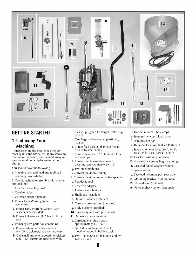
1.Unboxing Your Machine:
After opening the box, check the con-tents against the list below. If any items aremissing or damaged, call us right away sowe can send out a replacement at nocharge.
You should have the following:
1. Machine with toolhead and toolhead retaining pins installed
2. Operating handle assembly with washer and lock nut
3. Casefeed mounting post
4. Casefeed tube
5. Casefeed support bracket
6. Primer Early Warning System bag containing:
a. Primer Early Warning System (with AAA battery included)
b. Primer follower rod (16” black plastic rod)
7. Primer system parts bag containing:
a. Powder Measure Failsafe assem-bly (10” black metal rod w/ hardware)
b. One small and one large primer pickup tube – 12” aluminum tube each with
plastic tip - green tip (large), yellow tip (small)
c. One large and one small plastic tip, (spares)
d. Primer feed disk (2” diameter metaldisk w/16 small holes)
e. Primer magazine (15” aluminum tubew/ brass tip)
f. Primer punch assembly. (metal w/spring, approximately 2 x 1/2”)
g. Two steel hitchpins8. Conversion kit box (empty)
9. Conversion kit includes caliber specific:
a. Powder funnel
b. Casefeed adapter
c. Three locator buttons
d. Shellplate (installed)
e. Station 1 locator (installed)
f. Casefeed arm bushing (installed)
g. Body bushing (installed)
10. Powder system with powder die11. Accessory box containing:
a. Cartridge bin (blue plastic,approximately 3 x 4 x7”)
b. Ejected cartridge chute (black metal, wrapped in bubble pack)
c. Two 1/4” x 20 x 3”: hex bolts and two 1/4” x 20 nuts
d. Two Aluminum tube clamps
e. Spent primer cup (blue plastic)
f. Extra powder bar
g. Three die lockrings (7/8 x 14” thread)
h. Seven Allen wrenches (1/4”, 3/16”, 5/32”, 9/64”, 1/8”, 3/32”, 5/64”)
12. Casefeed assembly (optional)
13. Casefeed accessory bag containing:
a. Casefeed funnel adapter (white)
b. Spacer washer
c. Casefeed mounting post set screw
14. Mounting hardware kit (optional)
15. Three die set (optional)
16. Powder check system (optional)
11
1
16
4
5
3
8
6
7
2
9
13
14 15
1210
7
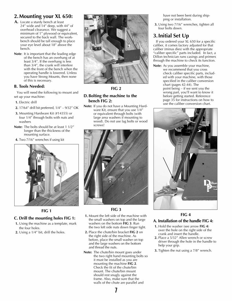
2.Mounting your XL 650:A. Locate a sturdy bench at least
24” wide and 14” deep, with 44” of overhead clearance. We suggest a minimum of 1” plywood or equivalent, secured to the back wall. The work-bench should be tall enough to place your eye level about 18” above the bench.
Note: It is important that the leading edgeof the bench has an overhang of atleast 3/4”. If the overhang is less than 3/4”, the crank will interfere with the front of the bench when the operating handle is lowered. Unlessyou have Strong Mounts, then none of this is necessary.
B. Tools Needed: You will need the following to mount and
set up your machine:
1. Electric drill
2. 17/64” drill bit preferred, 1/4” – 9/32” OK
3. Mounting Hardware Kit (#14355) orfour 1/4” through bolts with nuts and washers
Note: The bolts should be at least 1 1/2”longer than the thickness of the mounting surface.
4. Two 7/16” wrenches if using kit
FIG 1
C. Drill the mounting holes FIG 1:1. Using the machine as a template, mark
the four holes.2. Using a 1/4” bit, drill the holes.
FIG 2
D. Bolting the machine to thebench FIG 2:
Note: If you do not have a Mounting Hard-ware Kit, ensure that you use 1/4” or equivalent through bolts (with large area washers if mounting to wood). Do not use lag bolts or wood screws!
FIG 31. Mount the left side of the machine with
the small washers on top and the large washers on the bottom FIG 3. Run the two left side nuts down finger tight.
2. Place the chute/bin bracket FIG 2 on the right side of the machine. As before, place the small washer on top and the large washers on the bottom and thread the nuts.
Note: The chute/bin mount goes under the two right hand mounting bolts so it must be installed as you are mounting the machine FIG 2. Check the fit of the chute/bin mount. The chute/bin mount should rest snugly against the frame. Also, make sure that the walls of the chute are parallel and
have not been bent during ship-ping or installation.
3. Using two 7/16” wrenches, tighten all four bolts down.
3. Initial Set UpIf you ordered your XL 650 for a specific
caliber, it comes factory adjusted for thatcaliber (minus dies) with the appropriate“caliber specific” parts included. In fact, aDillon technician runs casings and primersthrough the machine to check its function.
Note: As you assemble your machine, we recommend that you cross check caliber specific parts, includ-ed with your machine, with those specified in the caliber conversion chart (pages 42-44). The point being – if we sent you the wrong part, you’ll want to know it before getting started. Reference page 35 for instructions on how to use the caliber conversion chart.
FIG 4A. Installation of the handle FIG 4:1. Hold the washer (see arrow FIG 4)
over the hole on the right side of the crank and insert the handle.
2. Place a 5/32” Allen wrench or screw driver through the hole in the handle to help your grip.
3. Tighten the nut using a 7/8” wrench.
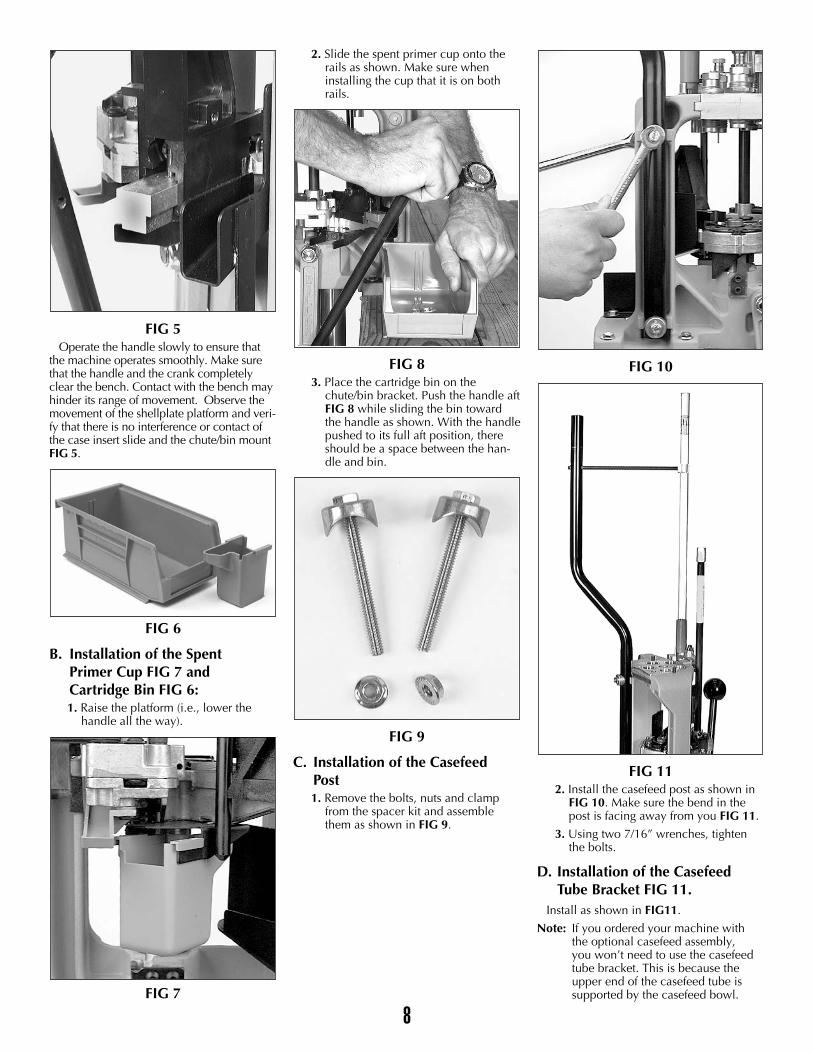
FIG 5Operate the handle slowly to ensure that
the machine operates smoothly. Make surethat the handle and the crank completelyclear the bench. Contact with the bench mayhinder its range of movement. Observe themovement of the shellplate platform and veri-fy that there is no interference or contact ofthe case insert slide and the chute/bin mountFIG 5.
FIG 6
B. Installation of the Spent Primer Cup FIG 7 and Cartridge Bin FIG 6:1. Raise the platform (i.e., lower the
handle all the way).
FIG 7
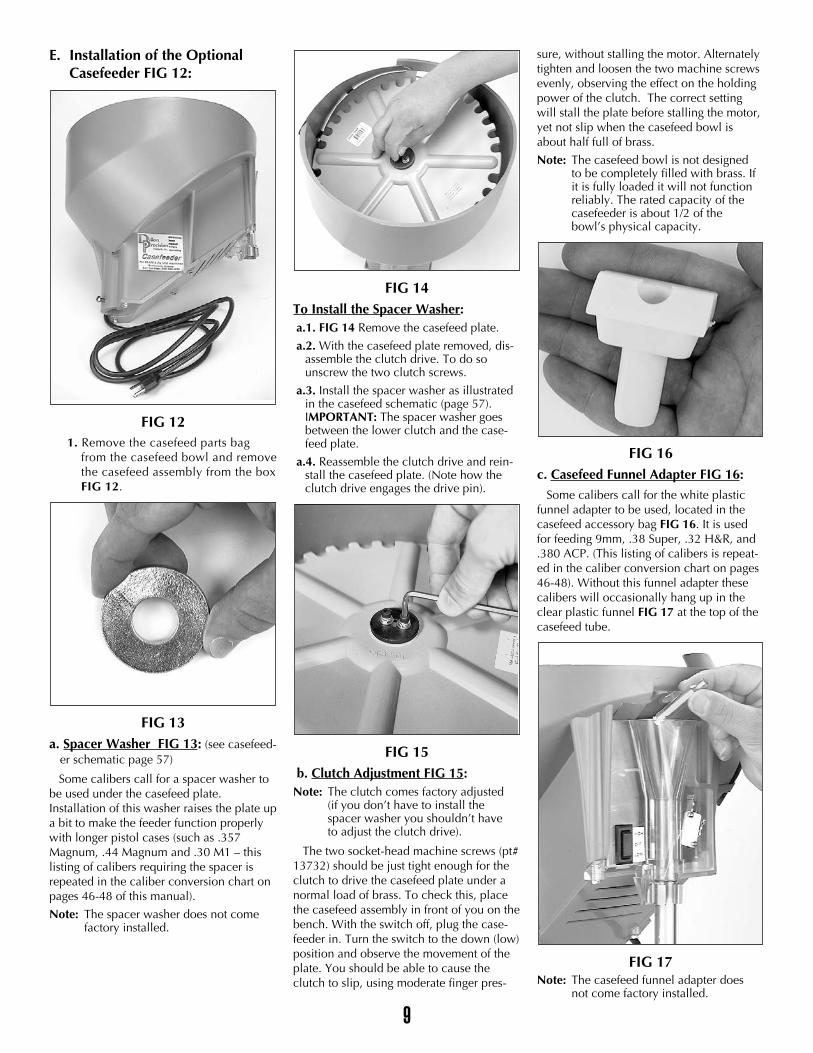
2. Slide the spent primer cup onto therails as shown. Make sure wheninstalling the cup that it is on bothrails.
FIG 83. Place the cartridge bin on the
chute/bin bracket. Push the handle aftFIG 8 while sliding the bin towardthe handle as shown. With the handlepushed to its full aft position, thereshould be a space between the han-dle and bin.
FIG 9
C. Installation of the Casefeed Post1. Remove the bolts, nuts and clamp
from the spacer kit and assemblethem as shown in FIG 9.
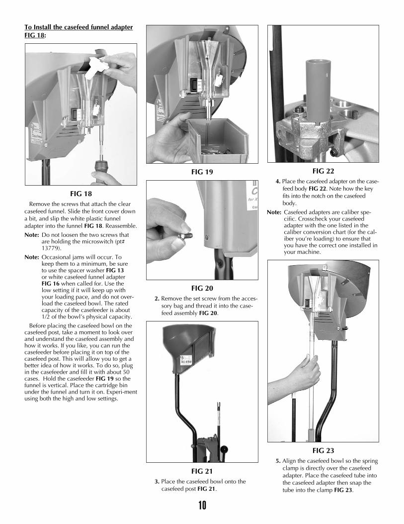
FIG 10
FIG 112. Install the casefeed post as shown in
FIG 10. Make sure the bend in thepost is facing away from you FIG 11.
3. Using two 7/16” wrenches, tightenthe bolts.
D. Installation of the Casefeed Tube Bracket FIG 11.
Install as shown in FIG11.
Note: If you ordered your machine with the optional casefeed assembly, you won’t need to use the casefeed tube bracket. This is because the upper end of the casefeed tube is supported by the casefeed bowl.
8
9
E. Installation of the Optional Casefeeder FIG 12:
FIG 121. Remove the casefeed parts bag
from the casefeed bowl and removethe casefeed assembly from the boxFIG 12.
FIG 13a. Spacer Washer FIG 13: (see casefeed-
er schematic page 57)
Some calibers call for a spacer washer tobe used under the casefeed plate.Installation of this washer raises the plate upa bit to make the feeder function properlywith longer pistol cases (such as .357Magnum, .44 Magnum and .30 M1 – thislisting of calibers requiring the spacer isrepeated in the caliber conversion chart onpages 46-48 of this manual).
Note: The spacer washer does not come factory installed.
FIG 14To Install the Spacer Washer:a.1. FIG 14 Remove the casefeed plate.
a.2. With the casefeed plate removed, dis-assemble the clutch drive. To do sounscrew the two clutch screws.
a.3. Install the spacer washer as illustratedin the casefeed schematic (page 57).IMPORTANT: The spacer washer goesbetween the lower clutch and the case-feed plate.
a.4. Reassemble the clutch drive and rein-stall the casefeed plate. (Note how theclutch drive engages the drive pin).
FIG 15b. Clutch Adjustment FIG 15:
Note: The clutch comes factory adjusted (if you don’t have to install the spacer washer you shouldn’t have to adjust the clutch drive).
The two socket-head machine screws (pt#13732) should be just tight enough for theclutch to drive the casefeed plate under anormal load of brass. To check this, placethe casefeed assembly in front of you on thebench. With the switch off, plug the case-feeder in. Turn the switch to the down (low)position and observe the movement of theplate. You should be able to cause theclutch to slip, using moderate finger pres-
sure, without stalling the motor. Alternatelytighten and loosen the two machine screwsevenly, observing the effect on the holdingpower of the clutch. The correct settingwill stall the plate before stalling the motor,yet not slip when the casefeed bowl isabout half full of brass.
Note: The casefeed bowl is not designed to be completely filled with brass. If it is fully loaded it will not function reliably. The rated capacity of the casefeeder is about 1/2 of the bowl’s physical capacity.
FIG 16c. Casefeed Funnel Adapter FIG 16:
Some calibers call for the white plasticfunnel adapter to be used, located in thecasefeed accessory bag FIG 16. It is usedfor feeding 9mm, .38 Super, .32 H&R, and.380 ACP. (This listing of calibers is repeat-ed in the caliber conversion chart on pages46-48). Without this funnel adapter thesecalibers will occasionally hang up in theclear plastic funnel FIG 17 at the top of thecasefeed tube.
FIG 17Note: The casefeed funnel adapter does
not come factory installed.
10
To Install the casefeed funnel adapterFIG 18:
FIG 18Remove the screws that attach the clear
casefeed funnel. Slide the front cover downa bit, and slip the white plastic funneladapter into the funnel FIG 18. Reassemble.
Note: Do not loosen the two screws that are holding the microswitch (pt# 13779).
Note: Occasional jams will occur. To keep them to a minimum, be sure to use the spacer washer FIG 13or white casefeed funnel adapter FIG 16 when called for. Use the low setting if it will keep up with your loading pace, and do not over-load the casefeed bowl. The rated capacity of the casefeeder is about 1/2 of the bowl’s physical capacity.
Before placing the casefeed bowl on thecasefeed post, take a moment to look overand understand the casefeed assembly andhow it works. If you like, you can run thecasefeeder before placing it on top of thecasefeed post. This will allow you to get abetter idea of how it works. To do so, plugin the casefeeder and fill it with about 50cases. Hold the casefeeder FIG 19 so thefunnel is vertical. Place the cartridge binunder the funnel and turn it on. Experi-mentusing both the high and low settings.
FIG 19
FIG 202. Remove the set screw from the acces-
sory bag and thread it into the case-feed assembly FIG 20.
FIG 213. Place the casefeed bowl onto the
casefeed post FIG 21.
FIG 224. Place the casefeed adapter on the case-
feed body FIG 22. Note how the keyfits into the notch on the casefeedbody.
Note: Casefeed adapters are caliber spe-cific. Crosscheck your casefeed adapter with the one listed in the caliber conversion chart (for the cal-iber you’re loading) to ensure that you have the correct one installed inyour machine.
FIG 235. Align the casefeed bowl so the spring
clamp is directly over the casefeedadapter. Place the casefeed tube intothe casefeed adapter then snap thetube into the clamp FIG 23.

11
Note: One end of the casefeed tube is beveled and one end is squared off.Insert the squared end of the tube (down) into the top of the casefeed adapter.
FIG 246. Using A 5/32” Allen wrench, snug
the machine screw against the case-feed mounting post FIG 24 to pre-vent the casefeed bowl from rotat-ing.
4.Toolhead OverviewYou’re now ready to install the toolhead
and adjust the dies. But first, we’ll give abrief overview of the location and functionof each station, we’ll then follow up with adetailed illustration.
FIG 25Station 1 - Sizing/Decapping
The stations on the toolhead are num-bered 1-5. Station 1 is for the sizing/decap-ping die FIG 25. This die can be easilyidentified by the decapping pin sticking outthe bottom as well as by its label. This dieremoves or “decaps” the old primer andresizes the case.
Warning: Never decap live primers! (See mandatory safety procedures.)
Station 2 - Powder Measure
FIG 26Station 2 is for the powder die, which
comes attached to the powder measureFIG 26. Here several operations are con-ducted. The case is primed, straightwalledpistol cases are belled, and powder isdropped. The purpose of the bell at themouth of the case is simply to help alignthe bullet and to keep the case from shav-ing lead during the seating process. Note:Only straight-walled cases receive a bell,bottle-necked cases (rifle cartridges) arenot belled.
FIG 27Station 3 - Powder Check
Station 3 is used for the optional powdercheck system FIG 27. This system is locatedin a separate package and can be identifiedby the blue warning buzzer attached to adie. This system is designed to detect grossdeviations in the powder charge, i.e. a dou-ble charge of powder or no powder at all.
Station 4 - Bullet SeatingStation 4 is for the seating die FIG 25.
This is where the bullet is pushed into thecase.
Station 5 - CrimpStation 5 is for the crimp die FIG 25. This
die not only removes the bell created atStation 2, but rolls the mouth of the caseinward to insure proper feeding and tosecure the bullet.
LUBRICATING BRASSTo lubricate brass, use “Dillon Case
Lubricant” (item# 13733).
Pistol – If you’re using a carbide sizingdie, you will not need to lubricate yourcases (before sizing) when loading straight-walled cases. If you’re not using a carbidesizing die, you must lube the brass beforesizing. We do, however, recommend lubri-cating all brass.
Rifle – Lubricate all bottle-necked cases,even if you’re using a carbide sizing die.
To lubricate your cases, start by ensur-ing that they are clean. Place your cleanbrass in a shallow box so the cases are lay-ing on their side. Pump a couple of spraysof Dillon Case Lubricant over the cases.Shake the box so the cases will tumble androll. Repeat this process again making surethat the lubricant is well distributed over thecases.
Note: When loading rifle cartridges, if your sizing die doesn’t have a carbide case mouth expander, you may want to allow a little bit of lube to get inside the case mouth.
Note: When loading bottle-necked cartridges, if you get an excessive amount of lube on the shoulder of the case, it will leave oil dents. Regardless of whether you’re lubricating pistol or rifle cases – do not drench the cases in lubricant. A light film of lubricant is sufficient.
Toolhead Head Setup:Pistol – go to page 12Rifle – go to page 20
12
PISTOL SECTION –Toolhead Set Up
To set up the toolhead you’ll need to haveempty brass, bullets, primers and powderon hand. (For your convenience DillonPrecision offers a wide variety of newprimed and unprimed brass, bullets, primersand powder.) For easy access, place yourbrass in an open container. Dillon Precisionalso offers a variety of blue bin boxes whichcome in handy for this purpose.
A. Station 1 – To install the size/decap die FIG 25:
Warning: Never attempt to de-prime liveprimers, an explosion may result inserious injury or even death.
1. Raise the platform, by lowering thehandle all the way down.
2. Screw the sizing die into Station 1.Continue to screw the die down untilit just touches the shellplate. Tightenthe die lockring finger tight Nowlower the platform by raising the han-dle to its upright position.
3. Place a case in the casefeed funnel.Here, the case drops to the casefeedarm bushing.
4. Raise the platform. The inserter campushes the feed arm bushing over thebody, dropping the case onto theStation 1 locator.
5. Lower the platform. The case is insert-ed into Station 1.
FIG 28Note: After raising the handle, insure that you push the handle against its full aftstop FIG 28. This will insure that the case is fully inserted into Station 1.
Note: Also, when priming, pushing the handle against its full aft stop, FIG 28, will insure that the primer is fully seated.
6. Again, raise the platform. The case isnow sized. If the case has a spentprimer, it will be deprimed. Leavethe platform in the raised positionwith the case fully inserted in thedie. This will ensure that the dieremains in alignment when tighten-ing the lockring.
FIG 297. Using a 1-1/8” wrench to turn the
lockring and a 7/8” wrench to holdthe die body, tighten the lockringFIG 29.
FIG 30
B. Station 1 – The decap-ping assembly FIG 30:
Dillon decapping assemblies are madewith replaceable decap pins. One extra pinis included with each sizing die. To replacea bent or broken pin, simply:
1. Unscrew the decapping assemblyfrom the top of the die FIG 30.
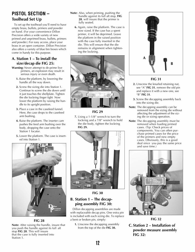
FIG 312. Unscrew the knurled retaining nut,
see “A” FIG 31, remove the old pinand replace it with a new one, see“B” FIG 31.
3. Screw the decapping assembly backinto the sizing die.
Note: The decapping assembly can be removed from the sizing die without affecting the adjustment of the siz-ing die or sizing operation.
Note: The decapping assembly must be removed when loading primed cases. (Tip: Check prices of components. You can often pur-chase primed cases for the price of the primers and new empty cases. Obviously, this is a good deal since you pay the same price and save time.)
FIG 32
C. Station 2 – Installation ofpowder measure assemblyFIG 32:
A
B
13
FIG 33
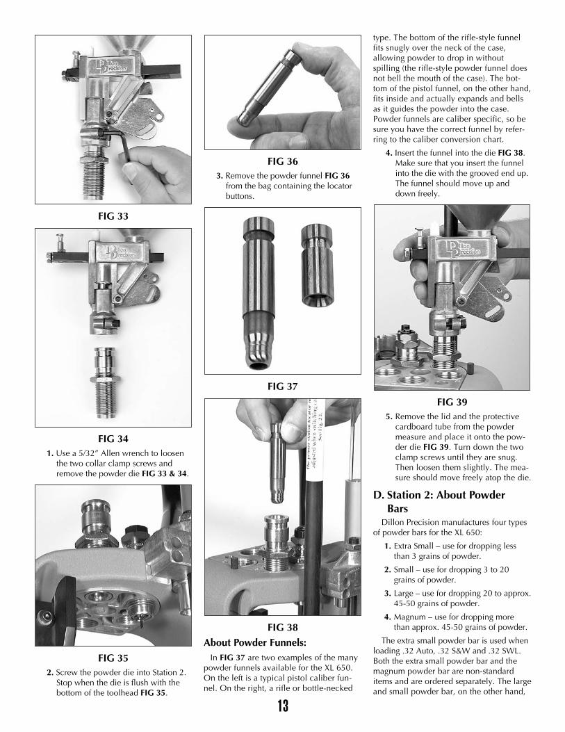
FIG 34 1. Use a 5/32” Allen wrench to loosen
the two collar clamp screws andremove the powder die FIG 33 & 34.
FIG 352. Screw the powder die into Station 2.
Stop when the die is flush with thebottom of the toolhead FIG 35.
FIG 363. Remove the powder funnel FIG 36
from the bag containing the locatorbuttons.
FIG 37
FIG 38About Powder Funnels:
In FIG 37 are two examples of the manypowder funnels available for the XL 650.On the left is a typical pistol caliber fun-nel. On the right, a rifle or bottle-necked
type. The bottom of the rifle-style funnelfits snugly over the neck of the case,allowing powder to drop in withoutspilling (the rifle-style powder funnel doesnot bell the mouth of the case). The bot-tom of the pistol funnel, on the other hand,fits inside and actually expands and bellsas it guides the powder into the case.Powder funnels are caliber specific, so besure you have the correct funnel by refer-ring to the caliber conversion chart.
4. Insert the funnel into the die FIG 38.Make sure that you insert the funnelinto the die with the grooved end up.The funnel should move up anddown freely.
FIG 395. Remove the lid and the protective
cardboard tube from the powdermeasure and place it onto the pow-der die FIG 39. Turn down the twoclamp screws until they are snug.Then loosen them slightly. The mea-sure should move freely atop the die.
D. Station 2: About Powder Bars
Dillon Precision manufactures four typesof powder bars for the XL 650:
1. Extra Small – use for dropping lessthan 3 grains of powder.
2. Small – use for dropping 3 to 20 grains of powder.
3. Large – use for dropping 20 to approx.45-50 grains of powder.
4. Magnum – use for dropping more than approx. 45-50 grains of powder.
The extra small powder bar is used whenloading .32 Auto, .32 S&W and .32 SWL.Both the extra small powder bar and themagnum powder bar are non-standarditems and are ordered separately. The largeand small powder bar, on the other hand,
14
are standard equipment and are includedwith every XL 650. If you ordered yourmachine set up for a specific caliber, theproper size powder bar should already beinstalled. If you need to change the pow-der bar – refer to “Powder Bar Adjust-ment” in the Caliber Conversion Sectionon page 30.
E. Station 2 – Adjustment of Powder Die & Powder Funnel:Note: Adjusting the powder die for a
straight wall case is not the same as adjusting a powder die for a bottle-necked case. This is because straight wall cases are given a bell and bottle-necked cases are not given a bell. Adjusting the powder die for a bottle-necked case is covered in the rifle section.
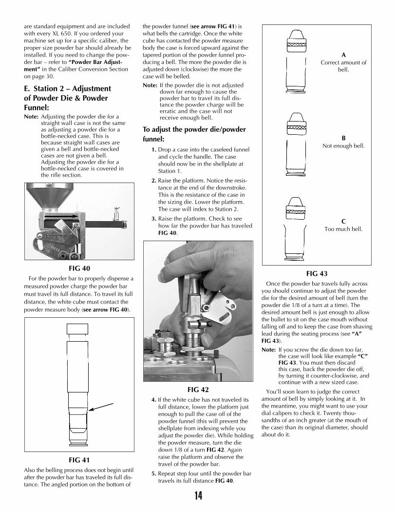
FIG 40For the powder bar to properly dispense a
measured powder charge the powder barmust travel its full distance. To travel its fulldistance, the white cube must contact thepowder measure body (see arrow FIG 40).
FIG 41Also the belling process does not begin untilafter the powder bar has traveled its full dis-tance. The angled portion on the bottom of
the powder funnel (see arrow FIG 41) iswhat bells the cartridge. Once the whitecube has contacted the powder measurebody the case is forced upward against thetapered portion of the powder funnel pro-ducing a bell. The more the powder die isadjusted down (clockwise) the more thecase will be belled.
Note: If the powder die is not adjusted down far enough to cause the powder bar to travel its full dis-tance the powder charge will be erratic and the case will not receive enough bell.
To adjust the powder die/powderfunnel:
1. Drop a case into the casefeed funneland cycle the handle. The caseshould now be in the shellplate atStation 1.
2. Raise the platform. Notice the resis-tance at the end of the downstroke.This is the resistance of the case inthe sizing die. Lower the platform.The case will index to Station 2.
3. Raise the platform. Check to seehow far the powder bar has traveledFIG 40.
FIG 424. If the white cube has not traveled its
full distance, lower the platform justenough to pull the case off of thepowder funnel (this will prevent theshellplate from indexing while youadjust the powder die). While holdingthe powder measure, turn the diedown 1/8 of a turn FIG 42. Againraise the platform and observe thetravel of the powder bar.
5. Repeat step four until the powder bartravels its full distance FIG 40.
FIG 43Once the powder bar travels fully across
you should continue to adjust the powderdie for the desired amount of bell (turn thepowder die 1/8 of a turn at a time). Thedesired amount bell is just enough to allowthe bullet to sit on the case mouth withoutfalling off and to keep the case from shavinglead during the seating process (see “A”FIG 43).
Note: If you screw the die down too far, the case will look like example “C” FIG 43. You must then discard this case, back the powder die off, by turning it counter-clockwise, and continue with a new sized case.
You’ll soon learn to judge the correctamount of bell by simply looking at it. Inthe meantime, you might want to use yourdial calipers to check it. Twenty thou-sandths of an inch greater (at the mouth ofthe case) than its original diameter, shouldabout do it.
ACorrect amount of
bell.
BNot enough bell.
CToo much bell.
15
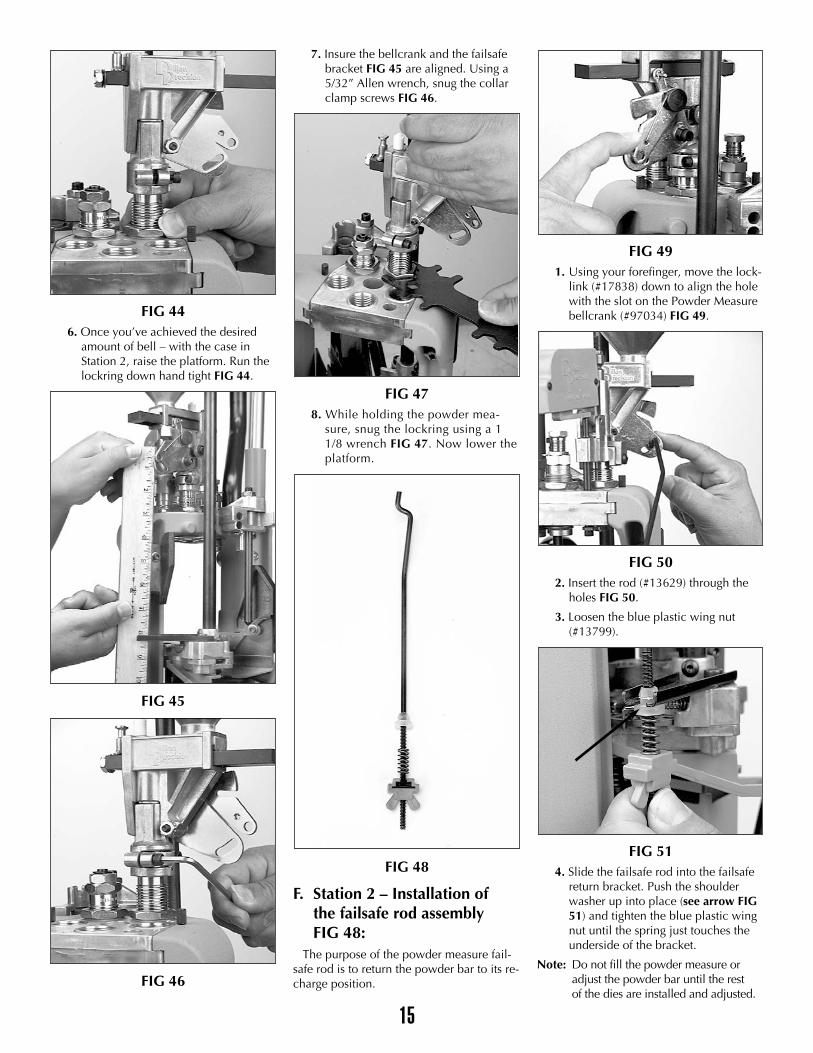
FIG 446. Once you’ve achieved the desired
amount of bell – with the case inStation 2, raise the platform. Run thelockring down hand tight FIG 44.
FIG 45
FIG 46
7. Insure the bellcrank and the failsafebracket FIG 45 are aligned. Using a5/32” Allen wrench, snug the collarclamp screws FIG 46.
FIG 478. While holding the powder mea-
sure, snug the lockring using a 11/8 wrench FIG 47. Now lower theplatform.
FIG 48
F. Station 2 – Installation ofthe failsafe rod assembly FIG 48:
The purpose of the powder measure fail-safe rod is to return the powder bar to its re-charge position.
FIG 491. Using your forefinger, move the lock-
link (#17838) down to align the holewith the slot on the Powder Measurebellcrank (#97034) FIG 49.
FIG 502. Insert the rod (#13629) through the
holes FIG 50.
3. Loosen the blue plastic wing nut(#13799).
FIG 514. Slide the failsafe rod into the failsafe
return bracket. Push the shoulderwasher up into place (see arrow FIG51) and tighten the blue plastic wingnut until the spring just touches theunderside of the bracket.
Note: Do not fill the powder measure or adjust the powder bar until the rest of the dies are installed and adjusted.
16
FIG 52
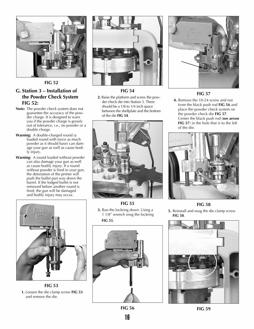
G. Station 3 – Installation of the Powder Check System FIG 52:
Note: The powder check system does not guarantee the accuracy of the pow-der charge. It is designed to warn you if the powder charge is grossly out of tolerance, i.e., no powder or a double charge.
Warning: A double-charged round (a loaded round with twice as much powder as it should have) can dam-age your gun as well as cause bodi-ly injury.
Warning: A round loaded without powder can also damage your gun as well as cause bodily injury. If a round without powder is fired in your gun, the detonation of the primer will push the bullet part way down the barrel. If the lodged bullet is not removed before another round is fired, the gun will be damaged and bodily injury may occur.
FIG 531. Loosen the die clamp screw FIG 53
and remove the die.
FIG 542. Raise the platform and screw the pow-
der check die into Station 3. Thereshould be a 1/8 to 1/4 inch spacebetween the shellplate and the bottomof the die FIG 54.
FIG 553. Run the lockring down. Using a
1 1/8” wrench snug the lockring
FIG 55.
FIG 56
FIG 574. Remove the 10-24 screw and nut
from the black push rod FIG 56 andplace the powder check system onthe powder check die FIG 57.Center the black push rod (see arrowFIG 57) in the hole that is to the leftof the die.
FIG 585. Reinstall and snug the die clamp screw
FIG 58.
FIG 59
17
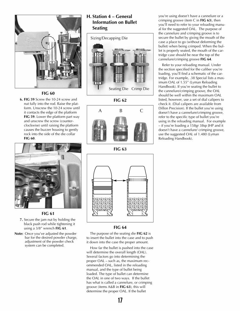
FIG 606. FIG 59 Screw the 10-24 screw and
nut fully into the rod. Raise the plat-form. Unscrew the 10-24 screw untilit contacts the edge of the platformFIG 59. Lower the platform part wayand unscrew the screw (counter-clockwise) until raising the platformcauses the buzzer housing to gentlyrock into the side of the die collarFIG 60.
FIG 617. Secure the jam nut by holding the
black push rod while tightening itusing a 3/8” wrench FIG 61.
Note: Once you’ve adjusted the powder bar for the desired powder charge, adjustment of the powder check system can be completed.
H. Station 4 – General Information on Bullet Seating
FIG 62
FIG 63
FIG 64The purpose of the seating die FIG 62 is
to insert the bullet into the case and to pushit down into the case the proper amount.
How far the bullet is pushed into the casewill determine the overall length (OAL).Several factors go into determining theproper OAL – such as, the maximum rec-ommended OAL, listed in the reloadingmanual, and the type of bullet beingloaded. The type of bullet can determinethe OAL in one of two ways. If the bullethas what is called a cannelure, or crimpinggroove (items A&B in FIG 63), this willdetermine the proper OAL. If the bullet
you’re using doesn’t have a cannelure or acrimping groove (item C in FIG 63), thenyou’ll need to refer to your reloading manu-al for the suggested OAL. The purpose ofthe cannelure and crimping groove is tosecure the bullet by giving the mouth of thecase a place to go (without deforming thebullet) when being crimped. When the bul-let is properly seated, the mouth of the car-tridge case should be near the top of thecannelure/crimping groove FIG 64.
Refer to your reloading manual. Underthe section specified for the caliber you’reloading, you’ll find a schematic of the car-tridge. For example, .38 Special lists a max-imum OAL of 1.55” (Lyman ReloadingHandbook). If you’re seating the bullet tothe cannelure/crimping groove, the OALshould be well within the maximum OALlisted, however, use a set of dial calipers tocheck it. (Dial calipers are available fromDillon Precision). If the bullet you’re usingdoesn’t have a cannelure/crimping groove,refer to the specific type of bullet you’reusing in the reloading manual. For example– if you’re loading a 158gr 38sp JHP and itdoesn’t have a cannelure/ crimping groove,use the suggested OAL of 1.480 (LymanReloading Handbook).
����������
����������
����������������������
����������
����������
����������������������
A
Sizing/Decapping Die
Seating Die Crimp Die
B C
18
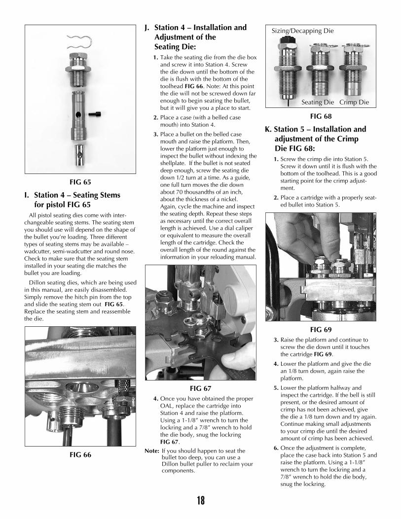
FIG 65
I. Station 4 – Seating Stems for pistol FIG 65
All pistol seating dies come with inter-changeable seating stems. The seating stemyou should use will depend on the shape ofthe bullet you’re loading. Three differenttypes of seating stems may be available –wadcutter, semi-wadcutter and round nose.Check to make sure that the seating steminstalled in your seating die matches thebullet you are loading.
Dillon seating dies, which are being usedin this manual, are easily disassembled.Simply remove the hitch pin from the topand slide the seating stem out FIG 65.Replace the seating stem and reassemblethe die.
FIG 66
J. Station 4 – Installation and Adjustment of the Seating Die:1. Take the seating die from the die box
and screw it into Station 4. Screwthe die down until the bottom of thedie is flush with the bottom of thetoolhead FIG 66. Note: At this pointthe die will not be screwed down farenough to begin seating the bullet,but it will give you a place to start.
2. Place a case (with a belled casemouth) into Station 4.
3. Place a bullet on the belled casemouth and raise the platform. Then,lower the platform just enough toinspect the bullet without indexing theshellplate. If the bullet is not seateddeep enough, screw the seating diedown 1/2 turn at a time. As a guide,one full turn moves the die downabout 70 thousandths of an inch,about the thickness of a nickel.Again, cycle the machine and inspectthe seating depth. Repeat these stepsas necessary until the correct overalllength is achieved. Use a dial caliperor equivalent to measure the overalllength of the cartridge. Check theoverall length of the round against theinformation in your reloading manual.
FIG 674. Once you have obtained the proper
OAL, replace the cartridge intoStation 4 and raise the platform.Using a 1-1/8” wrench to turn thelockring and a 7/8” wrench to holdthe die body, snug the lockringFIG 67.
Note: If you should happen to seat the bullet too deep, you can use a Dillon bullet puller to reclaim your components.
FIG 68
K. Station 5 – Installation and adjustment of the Crimp Die FIG 68:1. Screw the crimp die into Station 5.
Screw it down until it is flush with thebottom of the toolhead. This is a goodstarting point for the crimp adjust-ment.
2. Place a cartridge with a properly seat-ed bullet into Station 5.
FIG 693. Raise the platform and continue to
screw the die down until it touchesthe cartridge FIG 69.
4. Lower the platform and give the diean 1/8 turn down, again raise theplatform.
5. Lower the platform halfway andinspect the cartridge. If the bell is stillpresent, or the desired amount ofcrimp has not been achieved, givethe die a 1/8 turn down and try again.Continue making small adjustmentsto your crimp die until the desiredamount of crimp has been achieved.
6. Once the adjustment is complete,place the case back into Station 5 andraise the platform. Using a 1-1/8”wrench to turn the lockring and a7/8” wrench to hold the die body,snug the lockring.
Sizing/Decapping Die
Seating Die Crimp Die
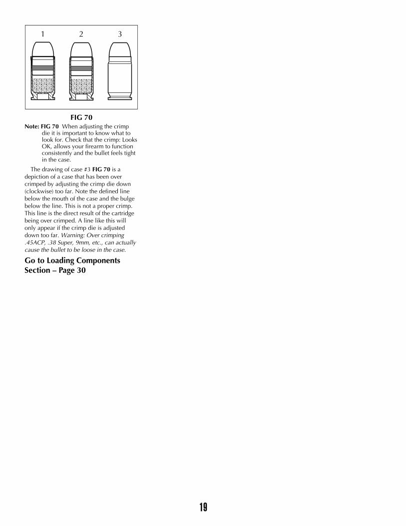
FIG 70Note: FIG 70 When adjusting the crimp
die it is important to know what tolook for. Check that the crimp: LooksOK, allows your firearm to functionconsistently and the bullet feels tightin the case.
The drawing of case #3 FIG 70 is adepiction of a case that has been overcrimped by adjusting the crimp die down(clockwise) too far. Note the defined linebelow the mouth of the case and the bulgebelow the line. This is not a proper crimp.This line is the direct result of the cartridgebeing over crimped. A line like this willonly appear if the crimp die is adjusteddown too far. Warning: Over crimping.45ACP, .38 Super, 9mm, etc., can actuallycause the bullet to be loose in the case.
Go to Loading ComponentsSection – Page 30
���������
��������������������������������
����������
����������
����������������������
����������
����������
19
1 2 3
RIFLE SECTION – Toolhead Set Up
To set up the toolhead you’ll need tohave your empty brass on hand. For yourconvenience Dillon Precision offers a widevariety of new primed and unprimed brass.For easy access, place your brass in anopen container. Dillon Precision also offersa variety of blue bin boxes which come inhandy for things like this.
FIG 71
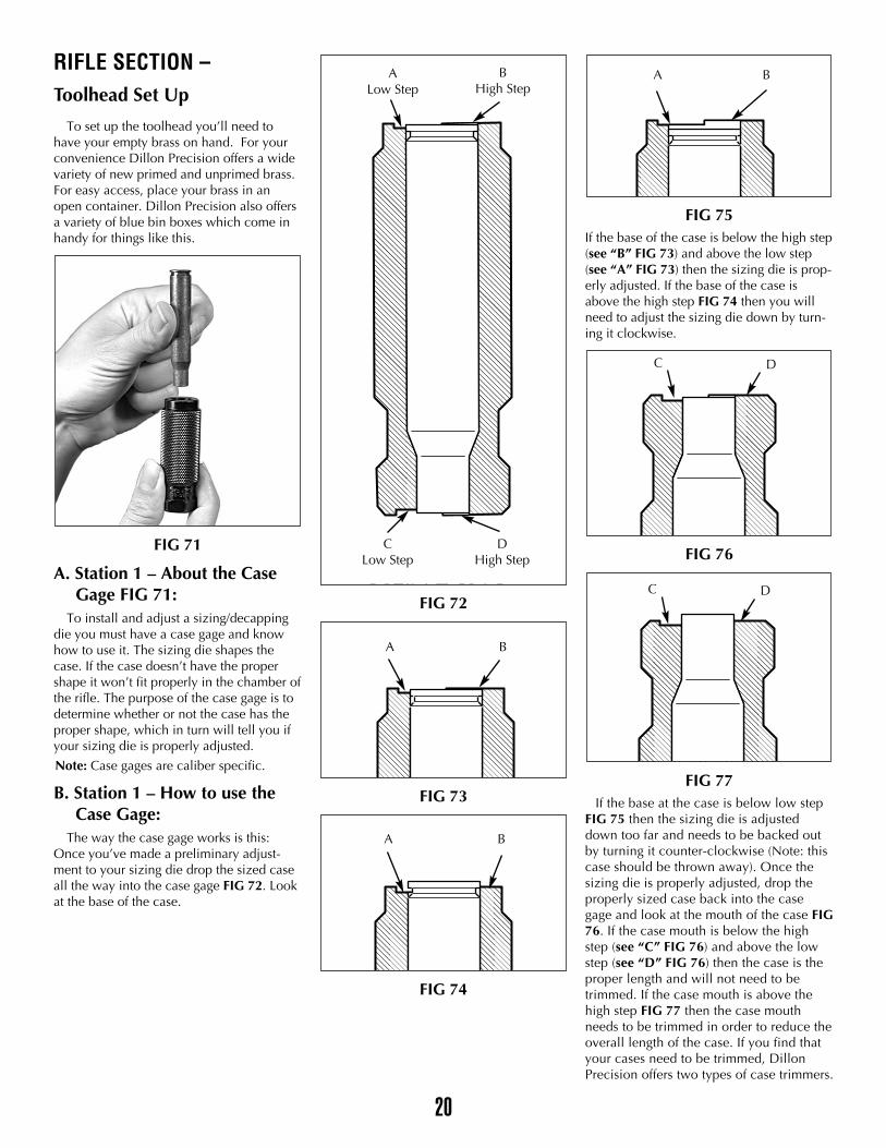
A. Station 1 – About the Case Gage FIG 71:
To install and adjust a sizing/decappingdie you must have a case gage and knowhow to use it. The sizing die shapes thecase. If the case doesn’t have the propershape it won’t fit properly in the chamber ofthe rifle. The purpose of the case gage is todetermine whether or not the case has theproper shape, which in turn will tell you ifyour sizing die is properly adjusted.
Note: Case gages are caliber specific.
B. Station 1 – How to use the Case Gage:
The way the case gage works is this:Once you’ve made a preliminary adjust-ment to your sizing die drop the sized caseall the way into the case gage FIG 72. Lookat the base of the case.
FIG 72
FIG 73
FIG 74
FIG 75If the base of the case is below the high step(see “B” FIG 73) and above the low step(see “A” FIG 73) then the sizing die is prop-erly adjusted. If the base of the case isabove the high step FIG 74 then you willneed to adjust the sizing die down by turn-ing it clockwise.
FIG 76
FIG 77If the base at the case is below low step
FIG 75 then the sizing die is adjusteddown too far and needs to be backed outby turning it counter-clockwise (Note: thiscase should be thrown away). Once thesizing die is properly adjusted, drop theproperly sized case back into the casegage and look at the mouth of the case FIG76. If the case mouth is below the highstep (see “C” FIG 76) and above the lowstep (see “D” FIG 76) then the case is theproper length and will not need to betrimmed. If the case mouth is above thehigh step FIG 77 then the case mouthneeds to be trimmed in order to reduce theoverall length of the case. If you find thatyour cases need to be trimmed, DillonPrecision offers two types of case trimmers.
������������
������������
��������
��������
��������
��������������������������������
Figs 72 & 73
20
ALow Step
BHigh Step
CLow Step
DHigh Step
A B
A B
C D
A B
C D
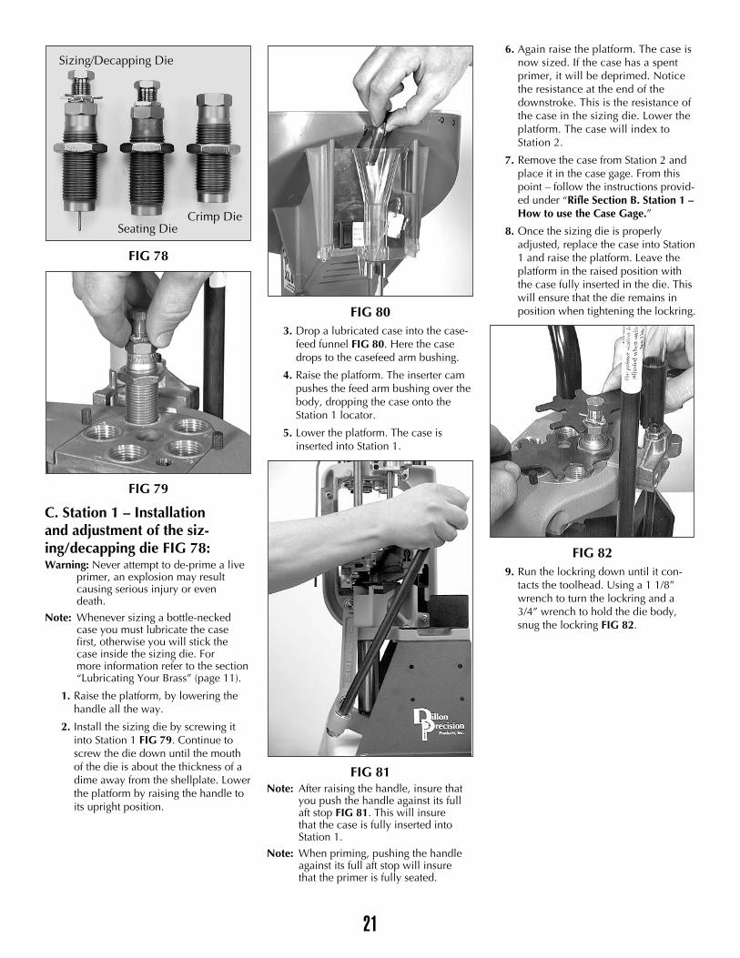
FIG 78
FIG 79
C. Station 1 – Installation and adjustment of the siz-ing/decapping die FIG 78:Warning: Never attempt to de-prime a live
primer, an explosion may result causing serious injury or even death.
Note: Whenever sizing a bottle-necked case you must lubricate the case first, otherwise you will stick the case inside the sizing die. For more information refer to the section “Lubricating Your Brass” (page 11).
1. Raise the platform, by lowering thehandle all the way.
2. Install the sizing die by screwing itinto Station 1 FIG 79. Continue toscrew the die down until the mouthof the die is about the thickness of adime away from the shellplate. Lowerthe platform by raising the handle toits upright position.
FIG 803. Drop a lubricated case into the case-
feed funnel FIG 80. Here the casedrops to the casefeed arm bushing.
4. Raise the platform. The inserter campushes the feed arm bushing over thebody, dropping the case onto theStation 1 locator.
5. Lower the platform. The case isinserted into Station 1.
FIG 81Note: After raising the handle, insure that
you push the handle against its full aft stop FIG 81. This will insure that the case is fully inserted into Station 1.
Note: When priming, pushing the handle against its full aft stop will insure that the primer is fully seated.
6. Again raise the platform. The case isnow sized. If the case has a spentprimer, it will be deprimed. Noticethe resistance at the end of thedownstroke. This is the resistance ofthe case in the sizing die. Lower theplatform. The case will index toStation 2.
7. Remove the case from Station 2 andplace it in the case gage. From thispoint – follow the instructions provid-ed under “Rifle Section B. Station 1 –How to use the Case Gage.”
8. Once the sizing die is properlyadjusted, replace the case into Station1 and raise the platform. Leave theplatform in the raised position withthe case fully inserted in the die. Thiswill ensure that the die remains inposition when tightening the lockring.
FIG 829. Run the lockring down until it con-
tacts the toolhead. Using a 1 1/8”wrench to turn the lockring and a3/4” wrench to hold the die body,snug the lockring FIG 82.
21
Sizing/Decapping Die
Seating DieCrimp Die
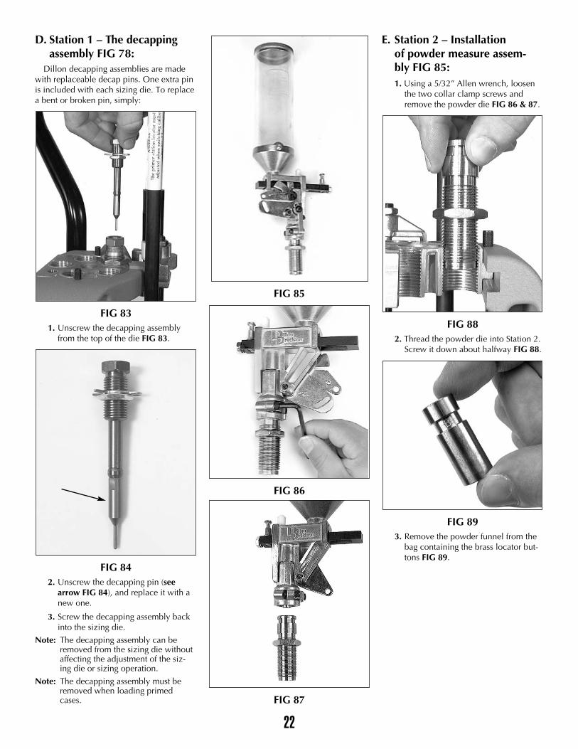
D. Station 1 – The decapping assembly FIG 78:
Dillon decapping assemblies are madewith replaceable decap pins. One extra pinis included with each sizing die. To replacea bent or broken pin, simply:
FIG 831. Unscrew the decapping assembly
from the top of the die FIG 83.
FIG 842. Unscrew the decapping pin (see
arrow FIG 84), and replace it with anew one.
3. Screw the decapping assembly backinto the sizing die.
Note: The decapping assembly can be removed from the sizing die without affecting the adjustment of the siz-ing die or sizing operation.
Note: The decapping assembly must be removed when loading primed cases.
FIG 85
FIG 86
FIG 87
E. Station 2 – Installation of powder measure assem-bly FIG 85:1. Using a 5/32” Allen wrench, loosen
the two collar clamp screws andremove the powder die FIG 86 & 87.
FIG 882. Thread the powder die into Station 2.
Screw it down about halfway FIG 88.
FIG 893. Remove the powder funnel from the
bag containing the brass locator but-tons FIG 89.
22
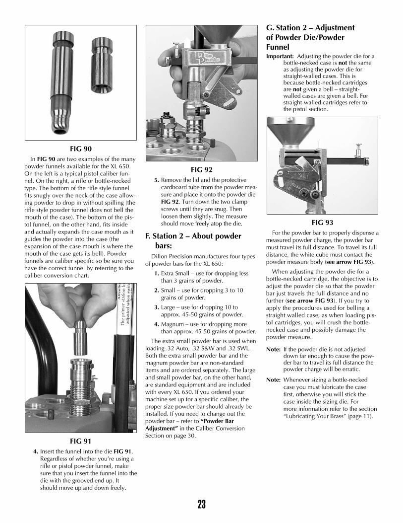
FIG 90In FIG 90 are two examples of the many
powder funnels available for the XL 650.On the left is a typical pistol caliber fun-nel. On the right, a rifle or bottle-neckedtype. The bottom of the rifle style funnelfits snugly over the neck of the case allow-ing powder to drop in without spilling (therifle style powder funnel does not bell themouth of the case). The bottom of the pis-tol funnel, on the other hand, fits insideand actually expands the case mouth as itguides the powder into the case (theexpansion of the case mouth is where themouth of the case gets its bell). Powderfunnels are caliber specific so be sure youhave the correct funnel by referring to thecaliber conversion chart.
FIG 914. Insert the funnel into the die FIG 91.
Regardless of whether you’re using arifle or pistol powder funnel, makesure that you insert the funnel into thedie with the grooved end up. Itshould move up and down freely.
FIG 925. Remove the lid and the protective
cardboard tube from the powder mea-sure and place it onto the powder dieFIG 92. Turn down the two clampscrews until they are snug. Thenloosen them slightly. The measureshould move freely atop the die.
F. Station 2 – About powder bars:
Dillon Precision manufactures four typesof powder bars for the XL 650:
1. Extra Small – use for dropping lessthan 3 grains of powder.
2. Small – use for dropping 3 to 10grains of powder.
3. Large – use for dropping 10 toapprox. 45-50 grains of powder.
4. Magnum – use for dropping morethan approx. 45-50 grains of powder.
The extra small powder bar is used whenloading .32 Auto, .32 S&W and .32 SWL.Both the extra small powder bar and themagnum powder bar are non-standarditems and are ordered separately. The largeand small powder bar, on the other hand,are standard equipment and are includedwith every XL 650. If you ordered yourmachine set up for a specific caliber, theproper size powder bar should already beinstalled. If you need to change out thepowder bar – refer to “Powder BarAdjustment” in the Caliber ConversionSection on page 30.
G. Station 2 – Adjustment of Powder Die/Powder FunnelImportant: Adjusting the powder die for a
bottle-necked case is not the same as adjusting the powder die for straight-walled cases. This is because bottle-necked cartridges are not given a bell – straight-walled cases are given a bell. For straight-walled cartridges refer to the pistol section.
FIG 93For the powder bar to properly dispense a
measured powder charge, the powder barmust travel its full distance. To travel its fulldistance, the white cube must contact thepowder measure body (see arrow FIG 93).
When adjusting the powder die for abottle-necked cartridge, the objective is toadjust the powder die so that the powderbar just travels the full distance and nofurther (see arrow FIG 93). If you try toapply the procedures used for belling astraight walled case, as when loading pis-tol cartridges, you will crush the bottle-necked case and possibly damage thepowder measure.
Note: If the powder die is not adjusted down far enough to cause the pow-der bar to travel its full distance the powder charge will be erratic.
Note: Whenever sizing a bottle-necked case you must lubricate the case first, otherwise you will stick the case inside the sizing die. For more information refer to the section “Lubricating Your Brass” (page 11).
23
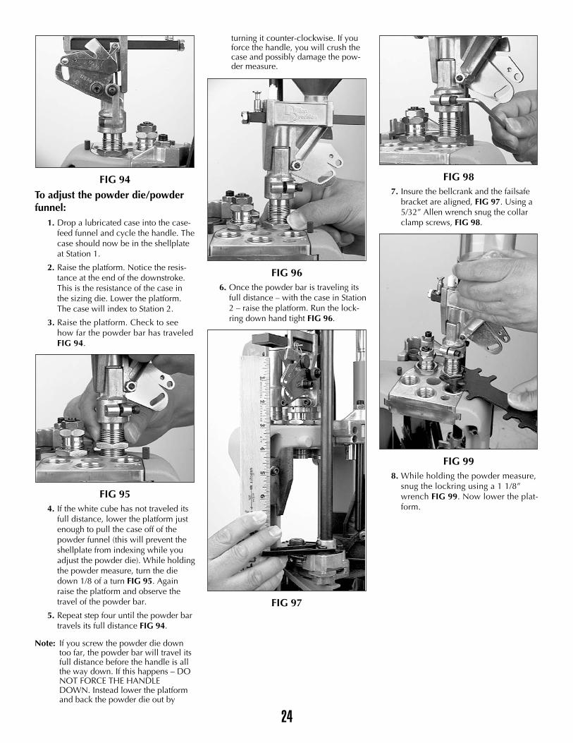
FIG 94To adjust the powder die/powderfunnel:
1. Drop a lubricated case into the case-feed funnel and cycle the handle. Thecase should now be in the shellplateat Station 1.
2. Raise the platform. Notice the resis-tance at the end of the downstroke.This is the resistance of the case inthe sizing die. Lower the platform.The case will index to Station 2.
3. Raise the platform. Check to seehow far the powder bar has traveledFIG 94.
FIG 954. If the white cube has not traveled its
full distance, lower the platform justenough to pull the case off of thepowder funnel (this will prevent theshellplate from indexing while youadjust the powder die). While holdingthe powder measure, turn the diedown 1/8 of a turn FIG 95. Againraise the platform and observe thetravel of the powder bar.
5. Repeat step four until the powder bartravels its full distance FIG 94.
Note: If you screw the powder die down too far, the powder bar will travel its full distance before the handle is all the way down. If this happens – DO NOT FORCE THE HANDLE DOWN. Instead lower the platform and back the powder die out by
turning it counter-clockwise. If you force the handle, you will crush the case and possibly damage the pow-der measure.
FIG 966. Once the powder bar is traveling its
full distance – with the case in Station2 – raise the platform. Run the lock-ring down hand tight FIG 96.
FIG 97
FIG 987. Insure the bellcrank and the failsafe
bracket are aligned, FIG 97. Using a5/32” Allen wrench snug the collarclamp screws, FIG 98.
FIG 998. While holding the powder measure,
snug the lockring using a 1 1/8”wrench FIG 99. Now lower the plat-form.
24
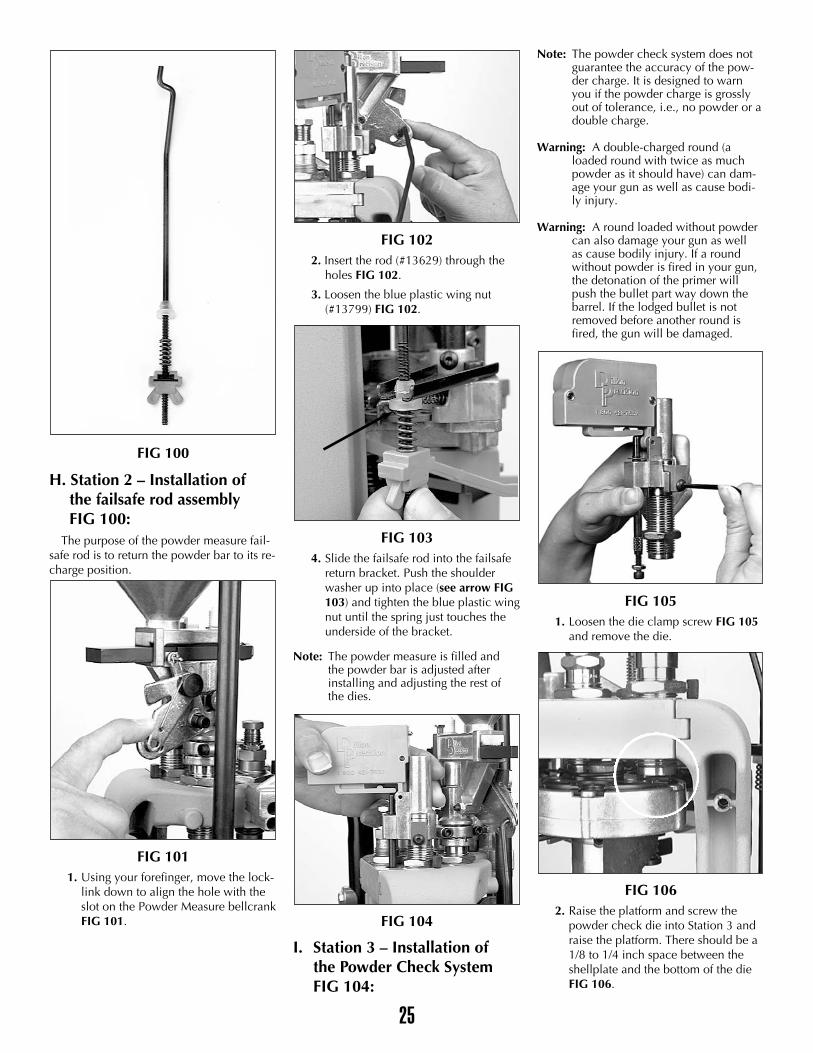
FIG 100
H. Station 2 – Installation of the failsafe rod assembly FIG 100:
The purpose of the powder measure fail-safe rod is to return the powder bar to its re-charge position.
FIG 1011. Using your forefinger, move the lock-
link down to align the hole with theslot on the Powder Measure bellcrankFIG 101.
FIG 1022. Insert the rod (#13629) through the
holes FIG 102.
3. Loosen the blue plastic wing nut(#13799) FIG 102.
FIG 1034. Slide the failsafe rod into the failsafe
return bracket. Push the shoulderwasher up into place (see arrow FIG103) and tighten the blue plastic wingnut until the spring just touches theunderside of the bracket.
Note: The powder measure is filled and the powder bar is adjusted after installing and adjusting the rest of the dies.
FIG 104
I. Station 3 – Installation of the Powder Check SystemFIG 104:
Note: The powder check system does not guarantee the accuracy of the pow-der charge. It is designed to warn you if the powder charge is grossly out of tolerance, i.e., no powder or a double charge.
Warning: A double-charged round (a loaded round with twice as much powder as it should have) can dam-age your gun as well as cause bodi-ly injury.
Warning: A round loaded without powder can also damage your gun as well as cause bodily injury. If a round without powder is fired in your gun, the detonation of the primer will push the bullet part way down the barrel. If the lodged bullet is not removed before another round is fired, the gun will be damaged.
FIG 1051. Loosen the die clamp screw FIG 105
and remove the die.
FIG 1062. Raise the platform and screw the
powder check die into Station 3 andraise the platform. There should be a1/8 to 1/4 inch space between theshellplate and the bottom of the dieFIG 106.
25
3. Run the lockring down. Using a 1-1/8” wrench snug the lockring.
FIG 107
FIG 1084. Remove the 10-24 screw and nut
from the black push rod FIG 107 andplace the powder check system onthe powder check die FIG 108.Center the black push rod (see arrowFIG 108) in the hole that is to the leftof the die.
FIG 1095. Reinstall and snug the die clamp
screw FIG 109.
FIG 110
FIG 1116. FIG 110 Screw the 10-24 screw and
nut fully into the rod. Raise the plat-form. Unscrew the 10-24 screwuntil it contacts the edge of the plat-form FIG 110. Lower the platformpart way and unscrew the screw(counter-clockwise) until raising the
platform causes the buzzer housingto rock into the side of the die collarFIG 111.
FIG 1127. Secure the jam nut by holding the
black push rod while tightening itusing a 3/8” wrench FIG 112.
Note: Once you’ve adjusted the powder bar for the desired powder charge – installation and adjustment of the powder check system can be com-pleted.
J. Station 4 – How to deter-mine the proper seating depth:
Before installing and adjusting the seatingdie you’ll need to know how to determinethe proper seating depth. How far the bulletis seated into the case will determine theoverall length (OAL). Several factors go intodetermining the proper OAL – such as, themaximum recommended OAL, listed in thereloading manual, and the type of bulletbeing loaded. The type of bullet can deter-mine the OAL by one of two ways. If thebullet has what is called a cannelure, FIG113, this will determine the proper OAL.
FIG 113
26
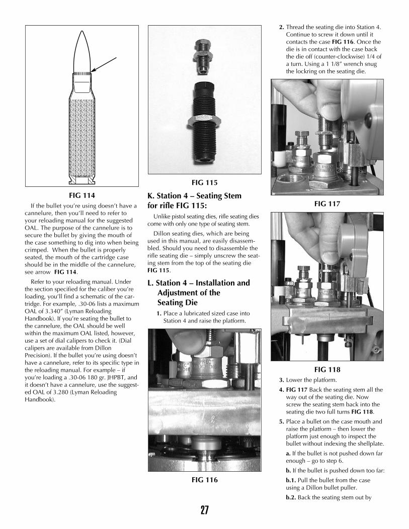
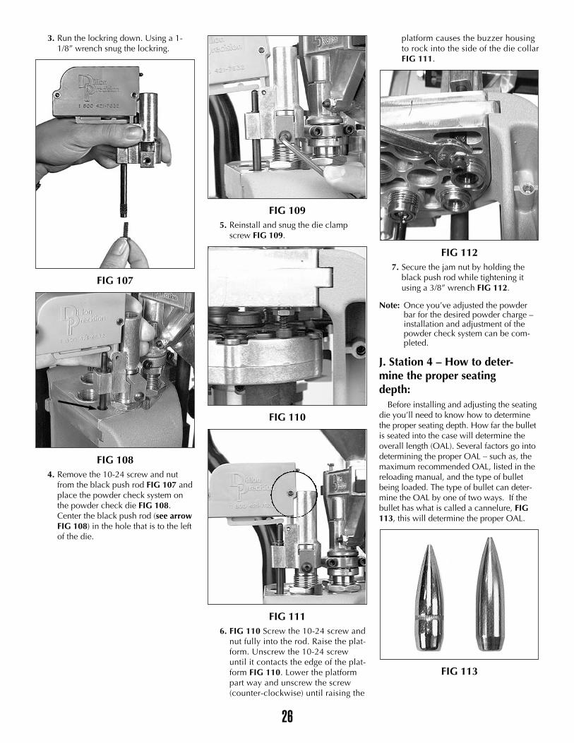
FIG 114If the bullet you’re using doesn’t have a
cannelure, then you’ll need to refer toyour reloading manual for the suggestedOAL. The purpose of the cannelure is tosecure the bullet by giving the mouth ofthe case something to dig into when beingcrimped. When the bullet is properlyseated, the mouth of the cartridge caseshould be in the middle of the cannelure,see arrow FIG 114.
Refer to your reloading manual. Underthe section specified for the caliber you’reloading, you’ll find a schematic of the car-tridge. For example, .30-06 lists a maximumOAL of 3.340” (Lyman ReloadingHandbook). If you’re seating the bullet tothe cannelure, the OAL should be wellwithin the maximum OAL listed, however,use a set of dial calipers to check it. (Dialcalipers are available from DillonPrecision). If the bullet you’re using doesn’thave a cannelure, refer to its specific type inthe reloading manual. For example – ifyou’re loading a .30-06 180 gr. JHPBT, andit doesn’t have a cannelure, use the suggest-ed OAL of 3.280 (Lyman ReloadingHandbook).
FIG 115
K. Station 4 – Seating Stem for rifle FIG 115:
Unlike pistol seating dies, rifle seating diescome with only one type of seating stem.
Dillon seating dies, which are beingused in this manual, are easily disassem-bled. Should you need to disassemble therifle seating die – simply unscrew the seat-ing stem from the top of the seating dieFIG 115.
L. Station 4 – Installation and Adjustment of the Seating Die1. Place a lubricated sized case into
Station 4 and raise the platform.
FIG 116
2. Thread the seating die into Station 4.Continue to screw it down until itcontacts the case FIG 116. Once thedie is in contact with the case backthe die off (counter-clockwise) 1/4 ofa turn. Using a 1 1/8” wrench snugthe lockring on the seating die.
FIG 117
FIG 1183. Lower the platform.
4. FIG 117 Back the seating stem all theway out of the seating die. Nowscrew the seating stem back into theseating die two full turns FIG 118.
5. Place a bullet on the case mouth andraise the platform – then lower theplatform just enough to inspect thebullet without indexing the shellplate.
a. If the bullet is not pushed down farenough – go to step 6.
b. If the bullet is pushed down too far:
b.1. Pull the bullet from the caseusing a Dillon bullet puller.
b.2. Back the seating stem out by
�����������������������������������������������������������������������������������������
������������������
������������������
27
turning it counter clockwise and tryagain.
6. Screw the seating stem down 1/2 turnat a time FIG 118.
FIG 1197. Repeat as necessary until the correct
overall length is achieved. Use a dialcaliper or equivalent to measure theoverall length of the cartridge FIG119. Check the overall length of theround against the information in yourreloading manual.
FIG 1208. Once you have obtained the proper
OAL, replace the cartridge intoStation 4, raise the platform andsnug the lockring on the seating stemFIG 120.
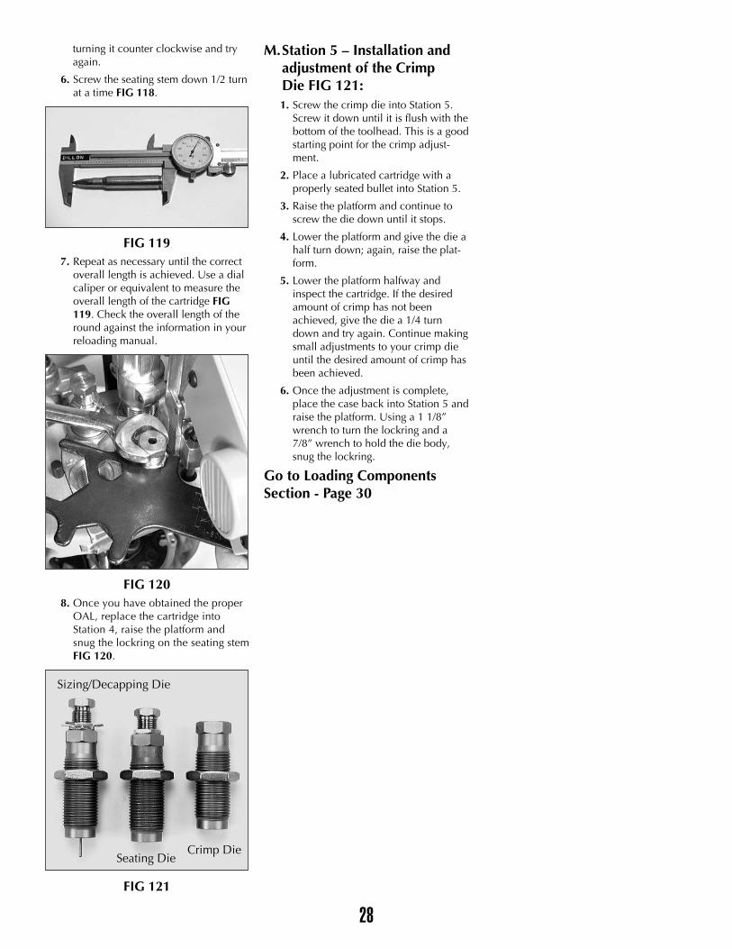
FIG 121
M.Station 5 – Installation and adjustment of the Crimp Die FIG 121:1. Screw the crimp die into Station 5.
Screw it down until it is flush with thebottom of the toolhead. This is a goodstarting point for the crimp adjust-ment.
2. Place a lubricated cartridge with aproperly seated bullet into Station 5.
3. Raise the platform and continue toscrew the die down until it stops.
4. Lower the platform and give the die ahalf turn down; again, raise the plat-form.
5. Lower the platform halfway andinspect the cartridge. If the desiredamount of crimp has not beenachieved, give the die a 1/4 turndown and try again. Continue makingsmall adjustments to your crimp dieuntil the desired amount of crimp hasbeen achieved.
6. Once the adjustment is complete,place the case back into Station 5 andraise the platform. Using a 1 1/8”wrench to turn the lockring and a7/8” wrench to hold the die body,snug the lockring.
Go to Loading ComponentsSection - Page 30
28
Sizing/Decapping Die
Seating DieCrimp Die
Final Assembly
FIG 122
FIG 123
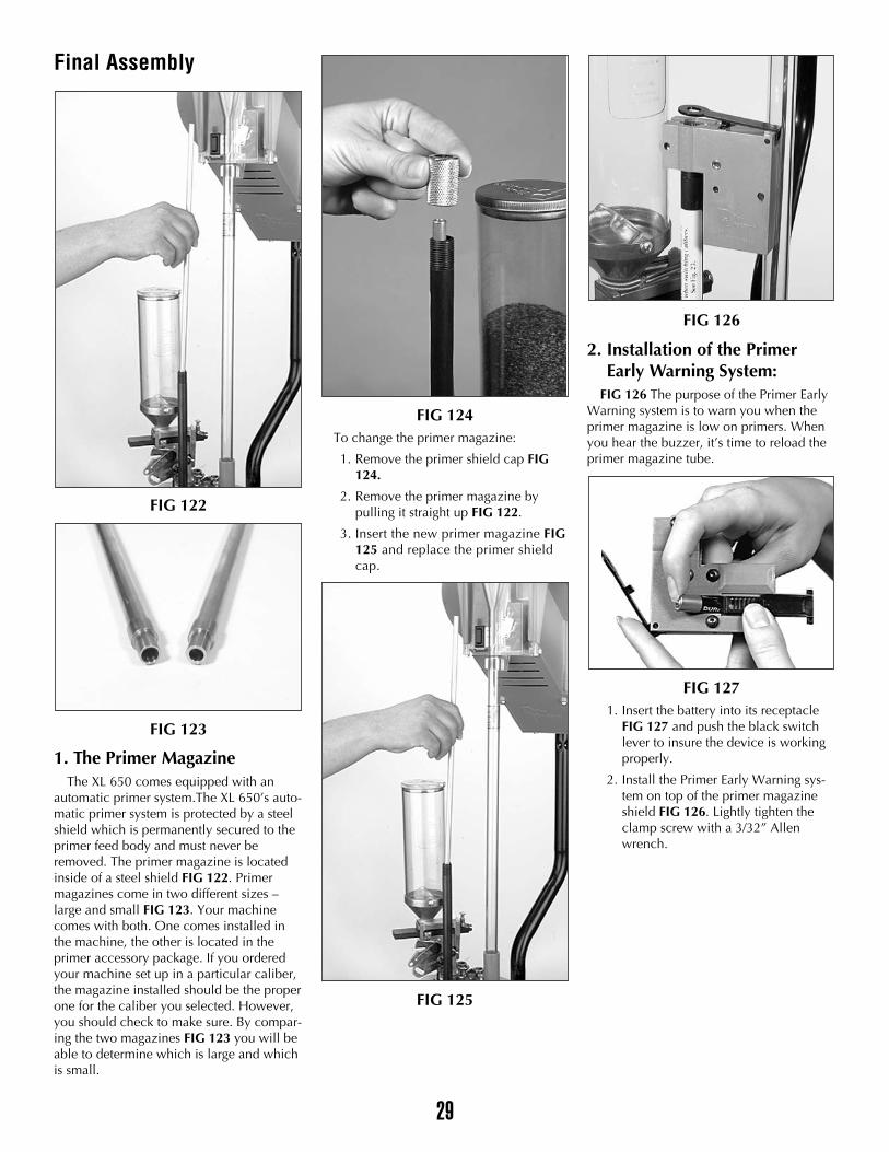
1. The Primer MagazineThe XL 650 comes equipped with an
automatic primer system.The XL 650’s auto-matic primer system is protected by a steelshield which is permanently secured to theprimer feed body and must never beremoved. The primer magazine is locatedinside of a steel shield FIG 122. Primermagazines come in two different sizes –large and small FIG 123. Your machinecomes with both. One comes installed inthe machine, the other is located in theprimer accessory package. If you orderedyour machine set up in a particular caliber,the magazine installed should be the properone for the caliber you selected. However,you should check to make sure. By compar-ing the two magazines FIG 123 you will beable to determine which is large and whichis small.
FIG 124To change the primer magazine:
1. Remove the primer shield cap FIG124.
2. Remove the primer magazine bypulling it straight up FIG 122.
3. Insert the new primer magazine FIG125 and replace the primer shieldcap.
FIG 125
FIG 126
2. Installation of the PrimerEarly Warning System:
FIG 126 The purpose of the Primer EarlyWarning system is to warn you when theprimer magazine is low on primers. Whenyou hear the buzzer, it’s time to reload theprimer magazine tube.
FIG 1271. Insert the battery into its receptacle
FIG 127 and push the black switchlever to insure the device is workingproperly.
2. Install the Primer Early Warning sys-tem on top of the primer magazineshield FIG 126. Lightly tighten theclamp screw with a 3/32” Allenwrench.
29
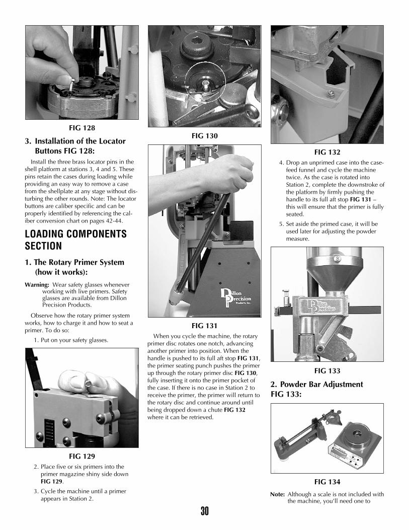
FIG 128
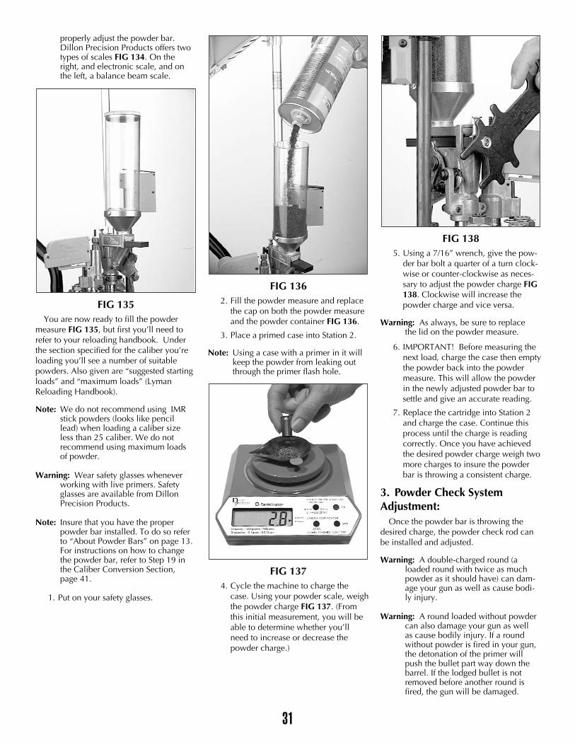
3. Installation of the Locator Buttons FIG 128:
Install the three brass locator pins in theshell platform at stations 3, 4 and 5. Thesepins retain the cases during loading whileproviding an easy way to remove a casefrom the shellplate at any stage without dis-turbing the other rounds. Note: The locatorbuttons are caliber specific and can beproperly identified by referencing the cal-iber conversion chart on pages 42-44.
LOADING COMPONENTSSECTION1. The Rotary Primer System
(how it works):
Warning: Wear safety glasses whenever working with live primers. Safety glasses are available from Dillon Precision Products.
Observe how the rotary primer systemworks, how to charge it and how to seat aprimer. To do so:
1. Put on your safety glasses.
FIG 1292. Place five or six primers into the
primer magazine shiny side downFIG 129.
3. Cycle the machine until a primerappears in Station 2.
FIG 130
FIG 131When you cycle the machine, the rotary
primer disc rotates one notch, advancinganother primer into position. When thehandle is pushed to its full aft stop FIG 131,the primer seating punch pushes the primerup through the rotary primer disc FIG 130,fully inserting it onto the primer pocket ofthe case. If there is no case in Station 2 toreceive the primer, the primer will return tothe rotary disc and continue around untilbeing dropped down a chute FIG 132where it can be retrieved.
FIG 1324. Drop an unprimed case into the case-
feed funnel and cycle the machinetwice. As the case is rotated intoStation 2, complete the downstroke ofthe platform by firmly pushing thehandle to its full aft stop FIG 131 –this will ensure that the primer is fullyseated.
5. Set aside the primed case, it will beused later for adjusting the powdermeasure.
FIG 133
2. Powder Bar AdjustmentFIG 133:
FIG 134
Note: Although a scale is not included withthe machine, you’ll need one to
30
31
properly adjust the powder bar. Dillon Precision Products offers two types of scales FIG 134. On the right, and electronic scale, and on the left, a balance beam scale.
FIG 135You are now ready to fill the powder
measure FIG 135, but first you’ll need torefer to your reloading handbook. Underthe section specified for the caliber you’reloading you’ll see a number of suitablepowders. Also given are “suggested startingloads” and “maximum loads” (LymanReloading Handbook).
Note: We do not recommend using IMR stick powders (looks like pencillead) when loading a caliber size less than 25 caliber. We do not recommend using maximum loads of powder.
Warning: Wear safety glasses whenever working with live primers. Safety glasses are available from Dillon Precision Products.
Note: Insure that you have the proper powder bar installed. To do so refer to “About Powder Bars” on page 13.For instructions on how to change the powder bar, refer to Step 19 in the Caliber Conversion Section, page 41.
1. Put on your safety glasses.
FIG 1362. Fill the powder measure and replace
the cap on both the powder measureand the powder container FIG 136.
3. Place a primed case into Station 2.
Note: Using a case with a primer in it will keep the powder from leaking out through the primer flash hole.
FIG 1374. Cycle the machine to charge the
case. Using your powder scale, weighthe powder charge FIG 137. (Fromthis initial measurement, you will beable to determine whether you’llneed to increase or decrease thepowder charge.)
FIG 1385. Using a 7/16” wrench, give the pow-
der bar bolt a quarter of a turn clock-wise or counter-clockwise as neces-sary to adjust the powder charge FIG138. Clockwise will increase thepowder charge and vice versa.
Warning: As always, be sure to replacethe lid on the powder measure.
6. IMPORTANT! Before measuring thenext load, charge the case then emptythe powder back into the powdermeasure. This will allow the powderin the newly adjusted powder bar tosettle and give an accurate reading.
7. Replace the cartridge into Station 2and charge the case. Continue thisprocess until the charge is readingcorrectly. Once you have achievedthe desired powder charge weigh twomore charges to insure the powderbar is throwing a consistent charge.
3. Powder Check System Adjustment:
Once the powder bar is throwing thedesired charge, the powder check rod canbe installed and adjusted.
Warning: A double-charged round (a loaded round with twice as much powder as it should have) can dam-age your gun as well as cause bodi-ly injury.
Warning: A round loaded without powder can also damage your gun as well as cause bodily injury. If a round without powder is fired in your gun, the detonation of the primer will push the bullet part way down the barrel. If the lodged bullet is not removed before another round is fired, the gun will be damaged.
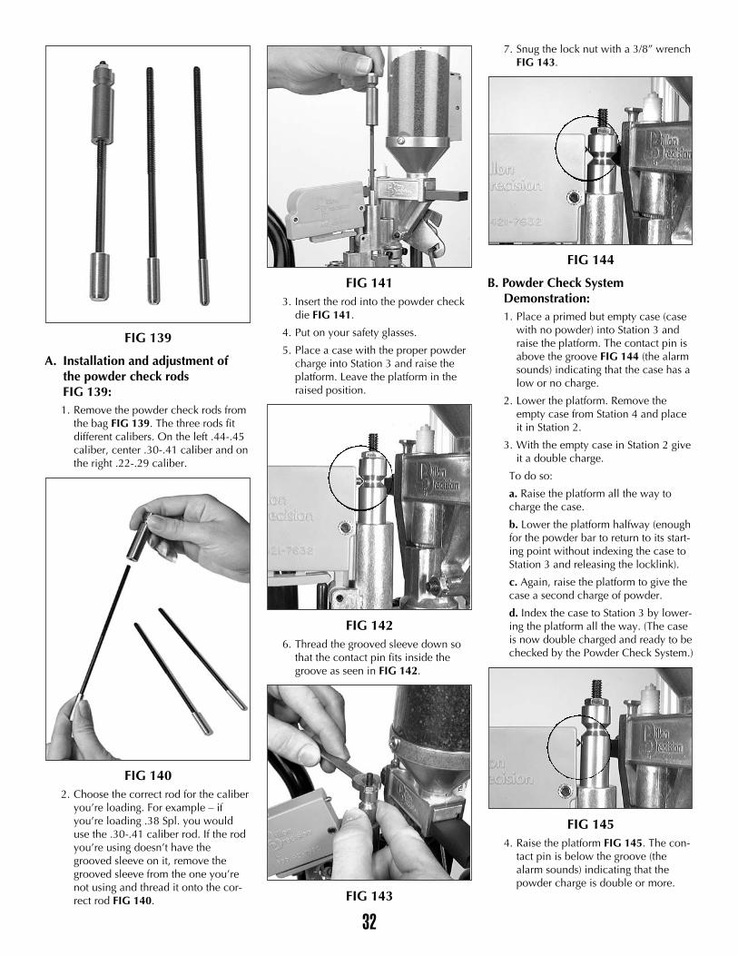
FIG 139
A. Installation and adjustment of the powder check rods FIG 139:1. Remove the powder check rods from
the bag FIG 139. The three rods fitdifferent calibers. On the left .44-.45caliber, center .30-.41 caliber and onthe right .22-.29 caliber.
FIG 1402. Choose the correct rod for the caliber
you’re loading. For example – ifyou’re loading .38 Spl. you woulduse the .30-.41 caliber rod. If the rodyou’re using doesn’t have thegrooved sleeve on it, remove thegrooved sleeve from the one you’renot using and thread it onto the cor-rect rod FIG 140.
FIG 1413. Insert the rod into the powder check
die FIG 141.
4. Put on your safety glasses.
5. Place a case with the proper powdercharge into Station 3 and raise theplatform. Leave the platform in theraised position.
FIG 1426. Thread the grooved sleeve down so
that the contact pin fits inside thegroove as seen in FIG 142.
FIG 143
7. Snug the lock nut with a 3/8” wrenchFIG 143.
FIG 144
B. Powder Check SystemDemonstration:1. Place a primed but empty case (case
with no powder) into Station 3 andraise the platform. The contact pin isabove the groove FIG 144 (the alarmsounds) indicating that the case has alow or no charge.
2. Lower the platform. Remove theempty case from Station 4 and placeit in Station 2.
3. With the empty case in Station 2 giveit a double charge.
To do so:
a. Raise the platform all the way tocharge the case.
b. Lower the platform halfway (enoughfor the powder bar to return to its start-ing point without indexing the case toStation 3 and releasing the locklink).
c. Again, raise the platform to give thecase a second charge of powder.
d. Index the case to Station 3 by lower-ing the platform all the way. (The caseis now double charged and ready to bechecked by the Powder Check System.)
FIG 1454. Raise the platform FIG 145. The con-
tact pin is below the groove (thealarm sounds) indicating that thepowder charge is double or more.
32
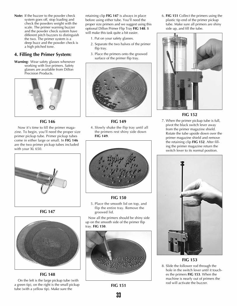
Note: If the buzzer to the powder check system goes off, stop loading and check the powders weight with the scale. The primer warning buzzer and the powder check system have different pitch buzzers to distinguish the two. The primer system is a deep buzz and the powder check is a high pitched tone.
4. Filling the Primer System:
Warning: Wear safety glasses whenever working with live primers. Safety glasses are available from Dillon Precision Products.
FIG 146Now it’s time to fill the primer maga-
zine. To begin, you’ll need the proper sizeprimer pickup tube. Primer pickup tubescome in either large or small. In FIG 146are the two primer pickup tubes includedwith your XL 650.
FIG 147
FIG 148On the left is the large pickup tube (with
a green tip), on the right is the small pickuptube (with a yellow tip). Make sure the
retaining clip FIG 147 is always in placebefore using either tube. You’ll need theproper size primers and we suggest using thisoptional Dillon Primer Flip Tray FIG 148. Itwill make this task quite a bit easier.
1. Put on your safety glasses.
2. Separate the two halves of the primerflip tray.
3. Place the primers onto the groovedsurface of the primer flip tray.
FIG 1494. Slowly shake the flip tray until all
the primers rest shiny side downFIG 149.
FIG 1505. Place the smooth lid on top, and
flip the entire tray. Remove thegrooved lid.
Now all the primers should be shiny sideup on the smooth side of the primer fliptray. FIG 150.
FIG 151
6. FIG 151 Collect the primers using theplastic tip end of the primer pickuptube. Make sure all primers are shinyside up, and fill the tube.
FIG 1527. When the primer pickup tube is full,
pivot the black switch lever awayfrom the primer magazine shield.Rotate the tube upside down over theprimer magazine shield and removethe retaining clip FIG 152. After fill-ing the primer magazine return theswitch lever to its normal position.
FIG 1538. Slide the follower rod through the
hole in the switch lever until it touch-es the primers FIG 153. When themachine is nearly out of primers therod will activate the buzzer.
33
Add some empty cases to your casefeederand turn the unit “on”. The motor will rununtil the clear casefeed tube fills and then itwill automatically shut off.
The reloading process on an XL 650begins with one complete stroke or cycle ofthe handle, which causes the first case to becycled through the casefeed system and fedinto the shellplate.
Station One
The first case is at station one of themachine and a new primer is ready at sta-tion 2. Move the handle down, the sizingdie reforms and also deprimes the first case.Return the handle to its rest position. Usinga smooth, fluid motion, move the handle upto its full aft stop to seat the new primer intothe case and release the handle. At thesame time, another case has been fed intothe shellplate.
Station TwoAgain, cycle the handle completely. The
first case now gets a charge of powder, thesecond case is resized and deprimed, thenthey both advance to the next stations.Using a smooth, fluid motion, move thehandle up to its full aft stop to seat thenew primer into the case. Return the han-dle to its rest position. Now three casesare in the shellplate.
Station ThreeCycle the handle. The first case enters the
powder checker, the second case is chargedwith powder and the third case is resizedand deprimed. Again, return the handle toits rest position and all the cases advance totheir next stations and the fourth case isinserted into the shellplate.
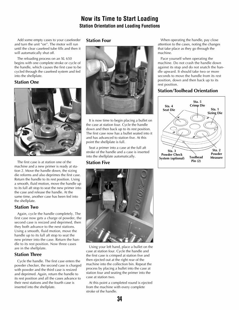
Station Four
It is now time to begin placing a bullet onthe case at station four. Cycle the handledown and then back up to its rest position.The first case now has a bullet seated into itand has advanced to station five. At thispoint the shellplate is full.
Seat a primer into a case at the full aftstroke of the handle and a case is insertedinto the shellplate automatically.
Station Five
Using your left hand, place a bullet on thecase at station four. Cycle the handle andthe first case is crimped at station five andthen ejected out at the right rear of themachine into the collection bin. Repeat theprocess by placing a bullet into the case atstation four and seating the primer into thecase at station two.
At this point a completed round is ejectedfrom the machine with every completestroke of the handle.
When operating the handle, pay closeattention to the cases, noting the changesthat take place as they go through themachine.
Pace yourself when operating themachine. Do not crash the handle downagainst its stop and do not snatch the han-dle upward. It should take two or moreseconds to move the handle from its restposition, down and then back up to itsrest position.
Station/Toolhead Orientation
34
Now its Time to Start LoadingStation Orientation and Loading Functions
Sta. 4Seat Die
Sta. 5Crimp Die
Sta. 1Sizing Die
Sta. 2PowderMeasureToolhead
Pin (2)
Sta. 3Powder Check
System (optional)
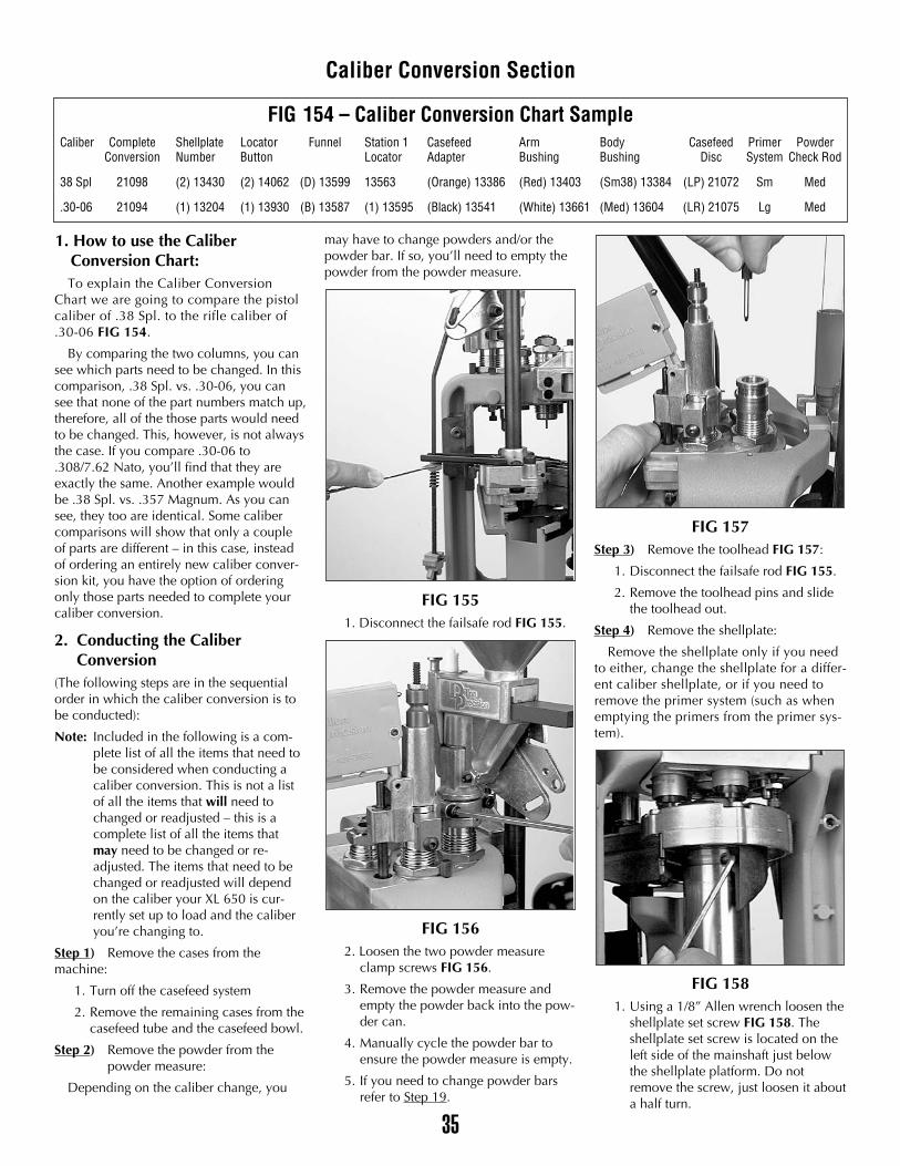
1. How to use the CaliberConversion Chart:To explain the Caliber Conversion
Chart we are going to compare the pistolcaliber of .38 Spl. to the rifle caliber of.30-06 FIG 154.
By comparing the two columns, you cansee which parts need to be changed. In thiscomparison, .38 Spl. vs. .30-06, you cansee that none of the part numbers match up,therefore, all of the those parts would needto be changed. This, however, is not alwaysthe case. If you compare .30-06 to.308/7.62 Nato, you’ll find that they areexactly the same. Another example wouldbe .38 Spl. vs. .357 Magnum. As you cansee, they too are identical. Some calibercomparisons will show that only a coupleof parts are different – in this case, insteadof ordering an entirely new caliber conver-sion kit, you have the option of orderingonly those parts needed to complete yourcaliber conversion.
2. Conducting the Caliber Conversion
(The following steps are in the sequentialorder in which the caliber conversion is tobe conducted):
Note: Included in the following is a com-plete list of all the items that need to be considered when conducting a caliber conversion. This is not a list of all the items that will need to changed or readjusted – this is a complete list of all the items that may need to be changed or re-adjusted. The items that need to be changed or readjusted will depend on the caliber your XL 650 is cur-rently set up to load and the caliber you’re changing to.
Step 1) Remove the cases from the machine:
1. Turn off the casefeed system
2. Remove the remaining cases from thecasefeed tube and the casefeed bowl.
Step 2) Remove the powder from the powder measure:
Depending on the caliber change, you
may have to change powders and/or thepowder bar. If so, you’ll need to empty thepowder from the powder measure.
FIG 1551. Disconnect the failsafe rod FIG 155.
FIG 1562. Loosen the two powder measure
clamp screws FIG 156.
3. Remove the powder measure andempty the powder back into the pow-der can.
4. Manually cycle the powder bar toensure the powder measure is empty.
5. If you need to change powder barsrefer to Step 19.
FIG 157Step 3) Remove the toolhead FIG 157:
1. Disconnect the failsafe rod FIG 155.
2. Remove the toolhead pins and slidethe toolhead out.
Step 4) Remove the shellplate:
Remove the shellplate only if you needto either, change the shellplate for a differ-ent caliber shellplate, or if you need toremove the primer system (such as whenemptying the primers from the primer sys-tem).
FIG 1581. Using a 1/8” Allen wrench loosen the
shellplate set screw FIG 158. Theshellplate set screw is located on theleft side of the mainshaft just belowthe shellplate platform. Do notremove the screw, just loosen it abouta half turn.
35
Caliber Conversion Section
FIG 154 – Caliber Conversion Chart SampleCaliber Complete Shellplate Locator Funnel Station 1 Casefeed Arm Body Casefeed Primer Powder
Conversion Number Button Locator Adapter Bushing Bushing Disc System Check Rod
38 Spl 21098 (2) 13430 (2) 14062 (D) 13599 13563 (Orange) 13386 (Red) 13403 (Sm38) 13384 (LP) 21072 Sm Med
.30-06 21094 (1) 13204 (1) 13930 (B) 13587 (1) 13595 (Black) 13541 (White) 13661 (Med) 13604 (LR) 21075 Lg Med
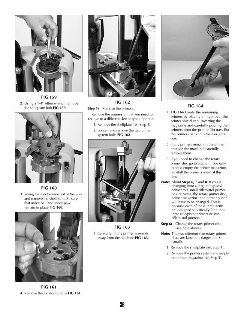
FIG 1592. Using a 1/4” Allen wrench remove
the shellplate bolt FIG 159.
FIG 1603. Swing the ejector wire out of the way
and remove the shellplate. Be surethat index ball and index pawlremain in place FIG 160.
FIG 1614. Remove the locator buttons FIG 161.
FIG 162Step 5) Remove the primers:
Remove the primers only if you need tochange to a different size or type of primer.
1. Remove the shellplate (ref. Step 4).
2. Loosen and remove the two primersystem bolts FIG 162.
FIG 1633. Carefully lift the primer assembly
away from the machine FIG 163.
FIG 1644. FIG 164 Empty the remaining
primers by placing a finger over theprimer shield cap, inverting themagazine and carefully pouring theprimers onto the primer flip tray. Putthe primers back into their originalbox.
5. If any primers remain in the primerarea (on the machine) carefullyremove them.
6. If you need to change the rotaryprimer disc go to Step 6. If you onlyto need empty the primer magazine,reinstall the primer system at thistime.
Note: About Steps 6, 7 and 8. If you’re changing from a large rifle/pistol primer to a small rifle/pistol primer or vice versa, the rotary primer disc, primer magazine, and primer punch will have to be changed. This is because each of these three items are designed specifically for either large rifle/pistol primers or small rifle/pistol primers.
Step 6) Change the rotary primer disc (see note above):
Note: The two different size rotary primer discs are labeled L (large) and S (small).
1. Remove the shellplate (ref. Step 4).
2. Remove the primer system and emptythe primer magazine (ref. Step 5).
36
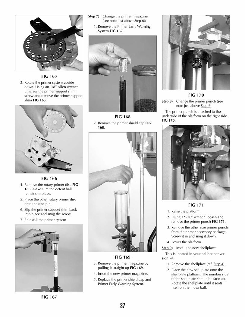
FIG 1653. Rotate the primer system upside
down. Using an 1/8” Allen wrenchunscrew the primer support shimscrew and remove the primer supportshim FIG 165.
FIG 1664. Remove the rotary primer disc FIG
166. Make sure the detent ballremains in place.
5. Place the other rotary primer disconto the disc pin.
6. Slip the primer support shim backinto place and snug the screw.
7. Reinstall the primer system.
FIG 167
Step 7) Change the primer magazine (see note just above Step 6):
1. Remove the Primer Early WarningSystem FIG 167.
FIG 1682. Remove the primer shield cap FIG
168.
FIG 1693. Remove the primer magazine by
pulling it straight up FIG 169.
4. Insert the new primer magazine.
5. Replace the primer shield cap andPrimer Early Warning System.
FIG 170Step 8) Change the primer punch (see
note just above Step 6):
The primer punch is attached to theunderside of the platform on the right sideFIG 170.
FIG 1711. Raise the platform.
2. Using a 9/16” wrench loosen andremove the primer punch FIG 171.
3. Remove the other size primer punchfrom the primer accessory package.Screw it in and snug it down.
4. Lower the platform.
Step 9) Install the new shellplate:
This is located in your caliber conver-sion kit.
1. Remove the shellplate (ref. Step 4).
2. Place the new shellplate onto theshellplate platform. The number sideof the shellplate should be face up.Rotate the shellplate until it seatsitself on the index ball.
37
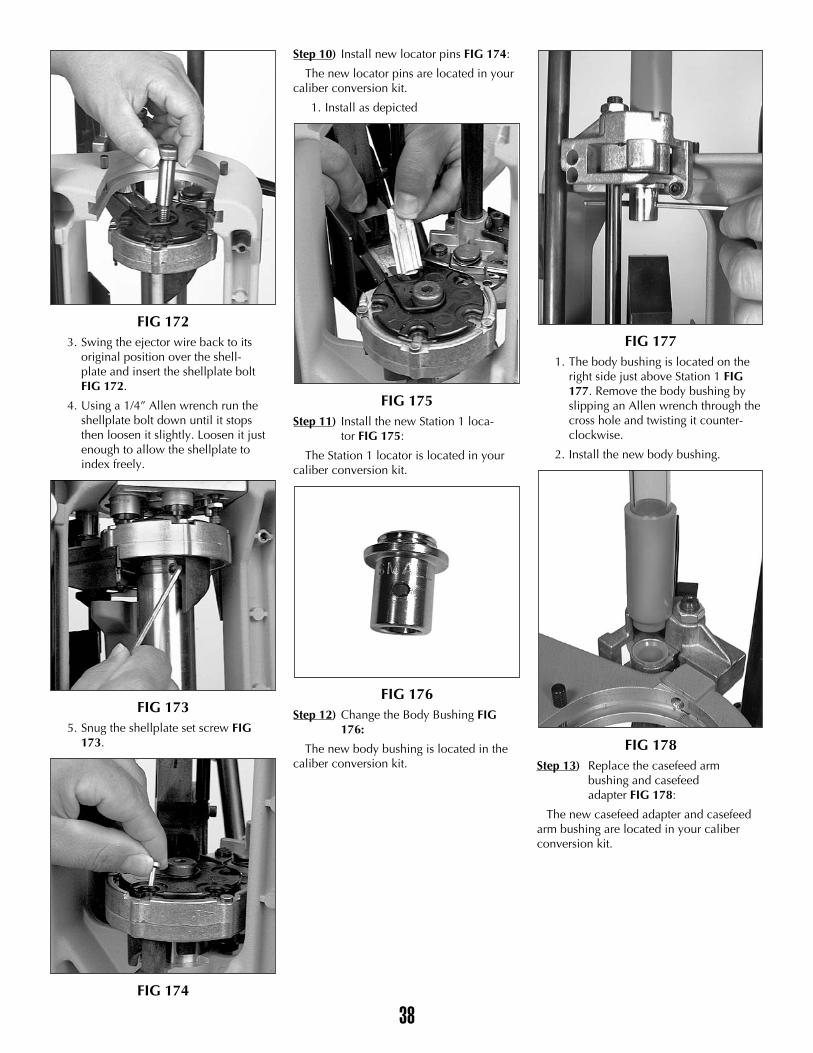
FIG 1723. Swing the ejector wire back to its
original position over the shell-plate and insert the shellplate boltFIG 172.
4. Using a 1/4” Allen wrench run theshellplate bolt down until it stopsthen loosen it slightly. Loosen it justenough to allow the shellplate toindex freely.
FIG 1735. Snug the shellplate set screw FIG
173.
FIG 174
Step 10) Install new locator pins FIG 174:
The new locator pins are located in yourcaliber conversion kit.
1. Install as depicted
FIG 175Step 11) Install the new Station 1 loca-
tor FIG 175:
The Station 1 locator is located in yourcaliber conversion kit.
FIG 176Step 12) Change the Body Bushing FIG
176:
The new body bushing is located in thecaliber conversion kit.
FIG 1771. The body bushing is located on the
right side just above Station 1 FIG177. Remove the body bushing byslipping an Allen wrench through thecross hole and twisting it counter-clockwise.
2. Install the new body bushing.
FIG 178Step 13) Replace the casefeed arm
bushing and casefeedadapter FIG 178:
The new casefeed adapter and casefeedarm bushing are located in your caliberconversion kit.
38
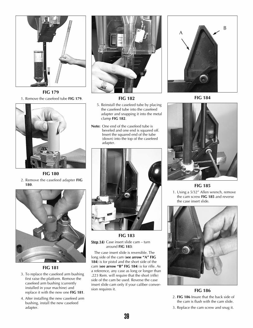
FIG 1791. Remove the casefeed tube FIG 179.
FIG 1802. Remove the casefeed adapter FIG
180.
FIG 1813. To replace the casefeed arm bushing
first raise the platform. Remove thecasefeed arm bushing (currentlyinstalled in your machine) andreplace it with the new one FIG 181.
4. After installing the new casefeed armbushing, install the new casefeedadapter.
FIG 1825. Reinstall the casefeed tube by placing
the casefeed tube into the casefeedadapter and snapping it into the metalclamp FIG 182.
Note: One end of the casefeed tube is beveled and one end is squared off.Insert the squared end of the tube (down) into the top of the casefeed adapter.
FIG 183Step 14) Case insert slide cam – turn
around FIG 183:
The case insert slide is reversible. Thelong side of the cam (see arrow “A” FIG184) is for pistol and the short side of thecam (see arrow “B” FIG 184) is for rifle. Asa reference, any case as long or longer than.223 Rem. will require that the short (rifle)side of the cam be used. Reverse the caseinsert slide cam only if your caliber conver-sion requires it.
FIG 184
FIG 1851. Using a 5/32” Allen wrench, remove
the cam screw FIG 185 and reversethe case insert slide.
FIG 1862. FIG 186 Insure that the back side of
the cam is flush with the cam slide.
3. Replace the cam screw and snug it.
39
BA
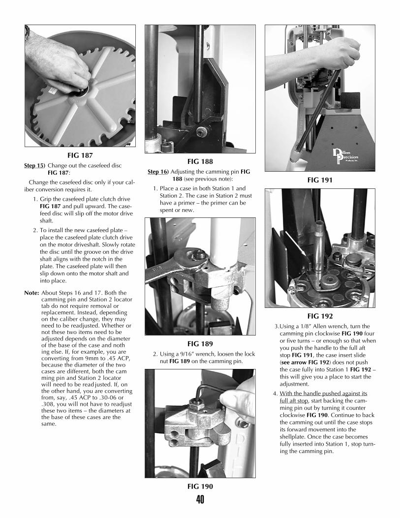
FIG 187Step 15) Change out the casefeed disc
FIG 187:
Change the casefeed disc only if your cal-iber conversion requires it.
1. Grip the casefeed plate clutch driveFIG 187 and pull upward. The case-feed disc will slip off the motor driveshaft.
2. To install the new casefeed plate –place the casefeed plate clutch driveon the motor driveshaft. Slowly rotatethe disc until the groove on the driveshaft aligns with the notch in theplate. The casefeed plate will thenslip down onto the motor shaft andinto place.
Note: About Steps 16 and 17. Both the camming pin and Station 2 locator tab do not require removal or replacement. Instead, depending on the caliber change, they may need to be readjusted. Whether or not these two items need to be adjusted depends on the diameter of the base of the case and nothing else. If, for example, you are converting from 9mm to .45 ACP, because the diameter of the two cases are different, both the camming pin and Station 2 locator will need to be read justed. If, on the other hand, you are converting from, say, .45 ACP to .30-06 or .308, you will not have to readjust these two items – the diameters at the base of these cases are the same.
FIG 188Step 16) Adjusting the camming pin FIG
188 (see previous note):
1. Place a case in both Station 1 andStation 2. The case in Station 2 musthave a primer – the primer can bespent or new.
FIG 1892. Using a 9/16” wrench, loosen the lock
nut FIG 189 on the camming pin.
FIG 190
FIG 191
FIG 1923.Using a 1/8” Allen wrench, turn the
camming pin clockwise FIG 190 fouror five turns – or enough so that whenyou push the handle to the full aftstop FIG 191, the case insert slide(see arrow FIG 192) does not pushthe case fully into Station 1 FIG 192 –this will give you a place to start theadjustment.
4. With the handle pushed against itsfull aft stop, start backing the cam-ming pin out by turning it counterclockwise FIG 190. Continue to backthe camming out until the case stopsits forward movement into theshellplate. Once the case becomesfully inserted into Station 1, stop turn-ing the camming pin.
40
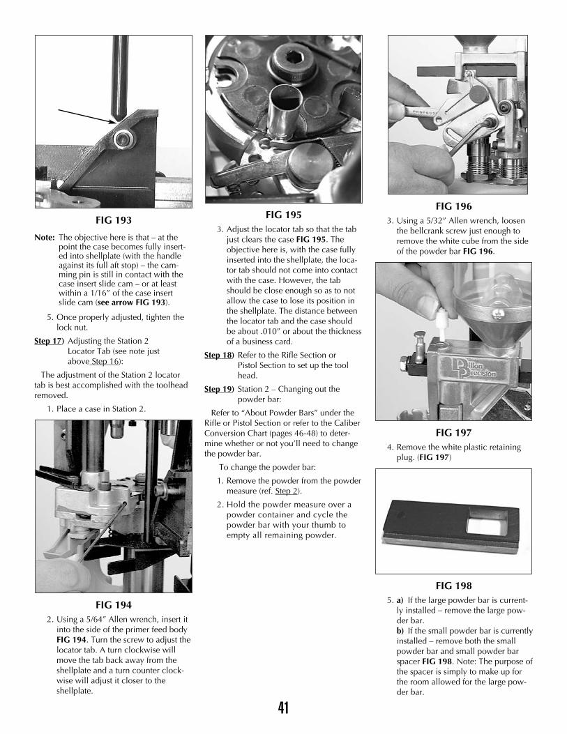
FIG 193
Note: The objective here is that – at the point the case becomes fully insert-ed into shellplate (with the handle against its full aft stop) – the cam-ming pin is still in contact with the case insert slide cam – or at least within a 1/16” of the case insert slide cam (see arrow FIG 193).
5. Once properly adjusted, tighten thelock nut.
Step 17) Adjusting the Station 2 Locator Tab (see note just above Step 16):
The adjustment of the Station 2 locatortab is best accomplished with the toolheadremoved.
1. Place a case in Station 2.
FIG 1942. Using a 5/64” Allen wrench, insert it
into the side of the primer feed bodyFIG 194. Turn the screw to adjust thelocator tab. A turn clockwise willmove the tab back away from theshellplate and a turn counter clock-wise will adjust it closer to theshellplate.
FIG 1953. Adjust the locator tab so that the tab
just clears the case FIG 195. Theobjective here is, with the case fullyinserted into the shellplate, the loca-tor tab should not come into contactwith the case. However, the tabshould be close enough so as to notallow the case to lose its position inthe shellplate. The distance betweenthe locator tab and the case shouldbe about .010” or about the thicknessof a business card.
Step 18) Refer to the Rifle Section or Pistol Section to set up the toolhead.
Step 19) Station 2 – Changing out the powder bar:
Refer to “About Powder Bars” under theRifle or Pistol Section or refer to the CaliberConversion Chart (pages 46-48) to deter-mine whether or not you’ll need to changethe powder bar.
To change the powder bar:
1. Remove the powder from the powdermeasure (ref. Step 2).
2. Hold the powder measure over apowder container and cycle thepowder bar with your thumb toempty all remaining powder.
FIG 1963. Using a 5/32” Allen wrench, loosen
the bellcrank screw just enough toremove the white cube from the sideof the powder bar FIG 196.
FIG 1974. Remove the white plastic retaining
plug. (FIG 197)
FIG 1985. a) If the large powder bar is current-
ly installed – remove the large pow-der bar.b) If the small powder bar is currentlyinstalled – remove both the smallpowder bar and small powder barspacer FIG 198. Note: The purpose ofthe spacer is simply to make up forthe room allowed for the large pow-der bar.
41
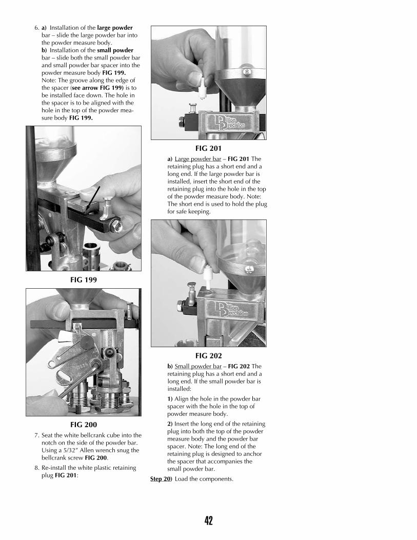
6. a) Installation of the large powderbar – slide the large powder bar intothe powder measure body.b) Installation of the small powderbar – slide both the small powder barand small powder bar spacer into thepowder measure body FIG 199.Note: The groove along the edge ofthe spacer (see arrow FIG 199) is tobe installed face down. The hole inthe spacer is to be aligned with thehole in the top of the powder mea-sure body FIG 199.
FIG 199
FIG 2007. Seat the white bellcrank cube into the
notch on the side of the powder bar.Using a 5/32” Allen wrench snug thebellcrank screw FIG 200.
8. Re-install the white plastic retainingplug FIG 201:
FIG 201a) Large powder bar – FIG 201 Theretaining plug has a short end and along end. If the large powder bar isinstalled, insert the short end of theretaining plug into the hole in the topof the powder measure body. Note:The short end is used to hold the plugfor safe keeping.
FIG 202b) Small powder bar – FIG 202 Theretaining plug has a short end and along end. If the small powder bar isinstalled:
1) Align the hole in the powder barspacer with the hole in the top ofpowder measure body.
2) Insert the long end of the retainingplug into both the top of the powdermeasure body and the powder barspacer. Note: The long end of theretaining plug is designed to anchorthe spacer that accompanies thesmall powder bar.
Step 20) Load the components.
42
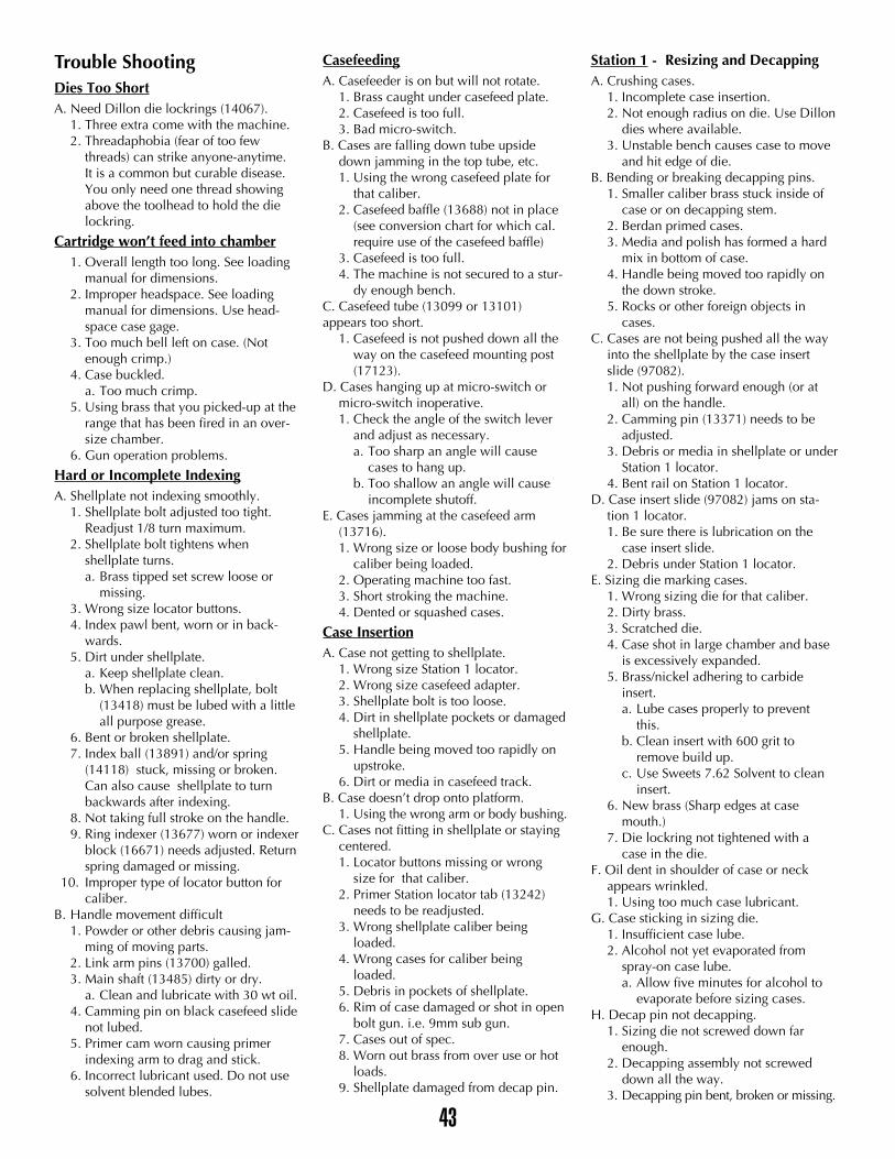
Trouble ShootingDies Too ShortA. Need Dillon die lockrings (14067).
1. Three extra come with the machine.2. Threadaphobia (fear of too few
threads) can strike anyone-anytime. It is a common but curable disease. You only need one thread showing above the toolhead to hold the die lockring.
Cartridge won’t feed into chamber1. Overall length too long. See loading
manual for dimensions.2. Improper headspace. See loading
manual for dimensions. Use head-space case gage.
3. Too much bell left on case. (Notenough crimp.)
4. Case buckled.a. Too much crimp.
5. Using brass that you picked-up at the range that has been fired in an over-size chamber.
6. Gun operation problems.
Hard or Incomplete IndexingA. Shellplate not indexing smoothly.
1. Shellplate bolt adjusted too tight. Readjust 1/8 turn maximum.
2. Shellplate bolt tightens when shellplate turns.a. Brass tipped set screw loose or
missing.3. Wrong size locator buttons.4. Index pawl bent, worn or in back-
wards.5. Dirt under shellplate.
a. Keep shellplate clean.b. When replacing shellplate, bolt
(13418) must be lubed with a littleall purpose grease.
6. Bent or broken shellplate.7. Index ball (13891) and/or spring
(14118) stuck, missing or broken. Can also cause shellplate to turn backwards after indexing.
8. Not taking full stroke on the handle.9. Ring indexer (13677) worn or indexer
block (16671) needs adjusted. Returnspring damaged or missing.
10. Improper type of locator button for caliber.
B. Handle movement difficult1. Powder or other debris causing jam-
ming of moving parts.2. Link arm pins (13700) galled.3. Main shaft (13485) dirty or dry.
a. Clean and lubricate with 30 wt oil.4. Camming pin on black casefeed slide
not lubed.5. Primer cam worn causing primer
indexing arm to drag and stick.6. Incorrect lubricant used. Do not use
solvent blended lubes.
CasefeedingA. Casefeeder is on but will not rotate.
1. Brass caught under casefeed plate.2. Casefeed is too full.3. Bad micro-switch.
B. Cases are falling down tube upside down jamming in the top tube, etc.1. Using the wrong casefeed plate for
that caliber.2. Casefeed baffle (13688) not in place
(see conversion chart for which cal. require use of the casefeed baffle)
3. Casefeed is too full.4. The machine is not secured to a stur-
dy enough bench.C. Casefeed tube (13099 or 13101) appears too short.
1. Casefeed is not pushed down all the way on the casefeed mounting post (17123).
D. Cases hanging up at micro-switch or micro-switch inoperative.1. Check the angle of the switch lever
and adjust as necessary.a. Too sharp an angle will cause
cases to hang up.b. Too shallow an angle will cause
incomplete shutoff.E. Cases jamming at the casefeed arm
(13716).1. Wrong size or loose body bushing for
caliber being loaded.2. Operating machine too fast.3. Short stroking the machine.4. Dented or squashed cases.
Case InsertionA. Case not getting to shellplate.
1. Wrong size Station 1 locator.2. Wrong size casefeed adapter.3. Shellplate bolt is too loose.4. Dirt in shellplate pockets or damaged
shellplate.5. Handle being moved too rapidly on
upstroke.6. Dirt or media in casefeed track.
B. Case doesn’t drop onto platform.1. Using the wrong arm or body bushing.
C. Cases not fitting in shellplate or staying centered.1. Locator buttons missing or wrong
size for that caliber.2. Primer Station locator tab (13242)
needs to be readjusted.3. Wrong shellplate caliber being
loaded.4. Wrong cases for caliber being
loaded.5. Debris in pockets of shellplate.6. Rim of case damaged or shot in open
bolt gun. i.e. 9mm sub gun.7. Cases out of spec.8. Worn out brass from over use or hot
loads.9. Shellplate damaged from decap pin.
Station 1 - Resizing and DecappingA. Crushing cases.
1. Incomplete case insertion.2. Not enough radius on die. Use Dillon
dies where available.3. Unstable bench causes case to move
and hit edge of die.B. Bending or breaking decapping pins.
1. Smaller caliber brass stuck inside of case or on decapping stem.
2. Berdan primed cases.3. Media and polish has formed a hard
mix in bottom of case.4. Handle being moved too rapidly on
the down stroke.5. Rocks or other foreign objects in
cases.C. Cases are not being pushed all the way
into the shellplate by the case insert slide (97082).1. Not pushing forward enough (or at
all) on the handle.2. Camming pin (13371) needs to be
adjusted.3. Debris or media in shellplate or under
Station 1 locator.4. Bent rail on Station 1 locator.
D. Case insert slide (97082) jams on sta-tion 1 locator.1. Be sure there is lubrication on the
case insert slide.2. Debris under Station 1 locator.
E. Sizing die marking cases.1. Wrong sizing die for that caliber.2. Dirty brass.3. Scratched die.4. Case shot in large chamber and base
is excessively expanded.5. Brass/nickel adhering to carbide
insert.a. Lube cases properly to prevent
this.b. Clean insert with 600 grit to
remove build up.c. Use Sweets 7.62 Solvent to clean
insert.6. New brass (Sharp edges at case
mouth.)7. Die lockring not tightened with a
case in the die.F. Oil dent in shoulder of case or neck
appears wrinkled.1. Using too much case lubricant.
G. Case sticking in sizing die.1. Insufficient case lube.2. Alcohol not yet evaporated from
spray-on case lube.a. Allow five minutes for alcohol to
evaporate before sizing cases.H. Decap pin not decapping.
1. Sizing die not screwed down far enough.
2. Decapping assembly not screwed down all the way.
3. Decapping pin bent, broken or missing.
43
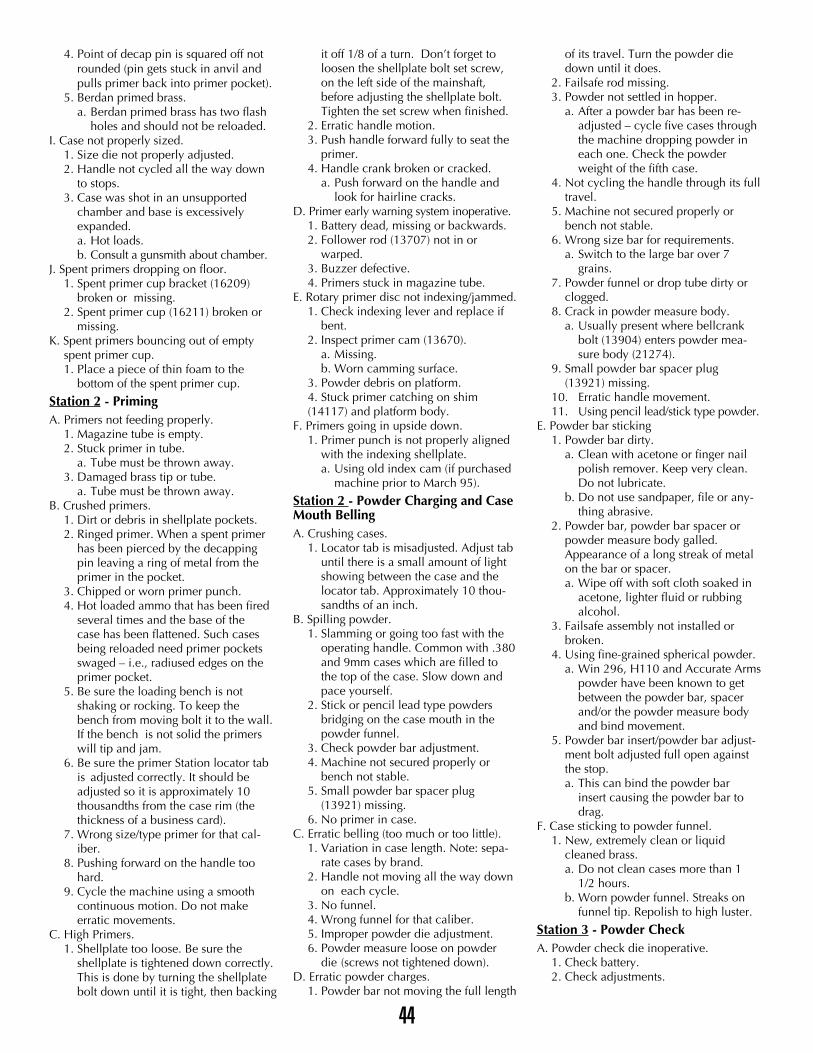
4. Point of decap pin is squared off not rounded (pin gets stuck in anvil and pulls primer back into primer pocket).
5. Berdan primed brass.a. Berdan primed brass has two flash
holes and should not be reloaded.I. Case not properly sized.
1. Size die not properly adjusted.2. Handle not cycled all the way down
to stops.3. Case was shot in an unsupported
chamber and base is excessively expanded.a. Hot loads.b. Consult a gunsmith about chamber.
J. Spent primers dropping on floor.1. Spent primer cup bracket (16209)
broken or missing.2. Spent primer cup (16211) broken or
missing.K. Spent primers bouncing out of empty
spent primer cup. 1. Place a piece of thin foam to the
bottom of the spent primer cup.
Station 2 - PrimingA. Primers not feeding properly.
1. Magazine tube is empty.2. Stuck primer in tube.
a. Tube must be thrown away.3. Damaged brass tip or tube.
a. Tube must be thrown away.B. Crushed primers.
1. Dirt or debris in shellplate pockets.2. Ringed primer. When a spent primer
has been pierced by the decapping pin leaving a ring of metal from the primer in the pocket.
3. Chipped or worn primer punch.4. Hot loaded ammo that has been fired
several times and the base of the case has been flattened. Such cases being reloaded need primer pockets swaged – i.e., radiused edges on the primer pocket.
5. Be sure the loading bench is not shaking or rocking. To keep the bench from moving bolt it to the wall.If the bench is not solid the primers will tip and jam.
6. Be sure the primer Station locator tabis adjusted correctly. It should be adjusted so it is approximately 10 thousandths from the case rim (the thickness of a business card).
7. Wrong size/type primer for that cal-iber.
8. Pushing forward on the handle too hard.
9. Cycle the machine using a smooth continuous motion. Do not make erratic movements.
C. High Primers.1. Shellplate too loose. Be sure the
shellplate is tightened down correctly. This is done by turning the shellplate bolt down until it is tight, then backing
it off 1/8 of a turn. Don’t forget to loosen the shellplate bolt set screw, on the left side of the mainshaft, before adjusting the shellplate bolt. Tighten the set screw when finished.
2. Erratic handle motion.3. Push handle forward fully to seat the
primer.4. Handle crank broken or cracked.
a. Push forward on the handle and look for hairline cracks.
D. Primer early warning system inoperative.1. Battery dead, missing or backwards.2. Follower rod (13707) not in or
warped.3. Buzzer defective.4. Primers stuck in magazine tube.
E. Rotary primer disc not indexing/jammed.1. Check indexing lever and replace if
bent.2. Inspect primer cam (13670).
a. Missing.b. Worn camming surface.
3. Powder debris on platform. 4. Stuck primer catching on shim (14117) and platform body.
F. Primers going in upside down.1. Primer punch is not properly aligned
with the indexing shellplate.a. Using old index cam (if purchased
machine prior to March 95).
Station 2 - Powder Charging and CaseMouth BellingA. Crushing cases.
1. Locator tab is misadjusted. Adjust tab until there is a small amount of light showing between the case and the locator tab. Approximately 10 thou-sandths of an inch.
B. Spilling powder.1. Slamming or going too fast with the
operating handle. Common with .380 and 9mm cases which are filled to the top of the case. Slow down and pace yourself.
2. Stick or pencil lead type powders bridging on the case mouth in the powder funnel.
3. Check powder bar adjustment.4. Machine not secured properly or
bench not stable.5. Small powder bar spacer plug
(13921) missing.6. No primer in case.
C. Erratic belling (too much or too little).1. Variation in case length. Note: sepa-
rate cases by brand.2. Handle not moving all the way down
on each cycle. 3. No funnel.4. Wrong funnel for that caliber.5. Improper powder die adjustment.6. Powder measure loose on powder
die (screws not tightened down).D. Erratic powder charges.
1. Powder bar not moving the full length
of its travel. Turn the powder die down until it does.
2. Failsafe rod missing.3. Powder not settled in hopper.
a. After a powder bar has been re-adjusted – cycle five cases through the machine dropping powder in each one. Check the powder weight of the fifth case.
4. Not cycling the handle through its full travel.
5. Machine not secured properly or bench not stable.
6. Wrong size bar for requirements.a. Switch to the large bar over 7
grains.7. Powder funnel or drop tube dirty or
clogged.8. Crack in powder measure body.
a. Usually present where bellcrank bolt (13904) enters powder mea-sure body (21274).
9. Small powder bar spacer plug (13921) missing.
10. Erratic handle movement.11. Using pencil lead/stick type powder.
E. Powder bar sticking1. Powder bar dirty.
a. Clean with acetone or finger nail polish remover. Keep very clean. Do not lubricate.
b. Do not use sandpaper, file or any-thing abrasive.
2. Powder bar, powder bar spacer or powder measure body galled. Appearance of a long streak of metal on the bar or spacer.a. Wipe off with soft cloth soaked in
acetone, lighter fluid or rubbing alcohol.
3. Failsafe assembly not installed or broken.
4. Using fine-grained spherical powder.a. Win 296, H110 and Accurate Arms
powder have been known to get between the powder bar, spacer and/or the powder measure body and bind movement.
5. Powder bar insert/powder bar adjust-ment bolt adjusted full open against the stop.a. This can bind the powder bar
insert causing the powder bar to drag.
F. Case sticking to powder funnel.1. New, extremely clean or liquid
cleaned brass.a. Do not clean cases more than 1
1/2 hours.b. Worn powder funnel. Streaks on
funnel tip. Repolish to high luster.
Station 3 - Powder CheckA. Powder check die inoperative.
1. Check battery.2. Check adjustments.
44
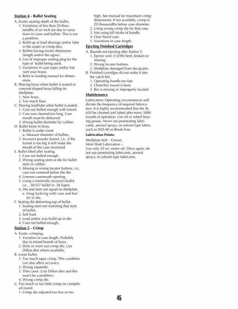
Station 4 - Bullet SeatingA. Erratic seating depth of the bullet.
1. Variations of less than 20 thou-sandths of an inch are due to varia-tions in cases and bullets. This is nota problem.
2. Build up of lead shavings and/or lubein the seater or crimp dies.
3. Bullets having erratic dimension (length and/or the ogive).
4. Use of improper seating plug for the type of bullet being used.
5. Variations in case types and/or lots (sort your brass).
6. Refer to loading manual for dimen-sions.
B. Shaving brass when bullet is seated or crescent shaped brass falling on shellplate.1. New brass.2. Too much flare.
C. Shaving lead/lube when bullet is seated.1. Case not belled enough with funnel.2. Case was cleaned too long. Case
mouth must be deburred.3. Wrong bullet diameter for caliber.
D. Bullet loose in brass.1. Bullet is under sized.
a. Measure diameter of bullets.2. Incorrect powder funnel, i.e., if the
funnel is too big it will make the mouth of the case oversized.
E. Bullet tilted after seating.1. Case not belled enough.2. Wrong seating stem or die for bullet
style or caliber.3. Missing or wrong locator buttons, i.e.,
case not centered below the die.4. Uneven casemouth opening.5. Using a nominally incorrect bullet.
i.e., .38/357 bullet in .38 Super.6. Die and stem not square to shellplate.
a. Snug lockring with case and bul-let in die.
F. Seating die deforming top of bullet.1. Seating stem not matching that style
of bullet.2. Soft lead.3. Lead and/or wax build-up in die.4. Case not belled enough.
Station 5 - CrimpA. Erratic crimping.
1. Variation in case length. Probably due to mixed brands of brass.
2. Dirty or worn out crimp die. Use Dillon dies where available.
B. Loose bullet.1. Too much taper crimp. This condition
can also affect accuracy.2. Wrong expander.3. Thin cases. (Use Dillon dies and this
won’t be a problem.)4. Wrong crimp die.
C. Too much or too little crimp on complet-ed round.1. Crimp die adjusted too low or too
high. See manual for maximum crimp dimensions. If not available, crimp to 20 thousandths below case diameter.
2. Using wrong crimp die for that case.3. Not using full stroke of handle.4. Over flared case.5. Variations in case length.
Ejecting Finished CartridgesA. Rounds not ejecting after Station 5.
1. Ejector wire (13298) bent, broken or missing.
2. Wrong locator buttons.3. Shellplate damaged from decap pin.
B. Finished cartridges do not make it into the catch bin.1. Operating handle too fast.2. Chute/bin mount is bent.3. Bin is missing or improperly located.
MaintenanceLubrication: Operating circumstances willdictate the frequency of required lubrica-tion. It is highly recommended that the XL650 be cleaned and lubed after every 3000rounds of operation. Use oil or wheel bear-ing grease. Never use penetrating lubri-cants, aerosol sprays, or solvent type lubes,such as WD-40 or Break Free.
Lubrication Points:
Shellplate bolt – Grease.Main Shaft Lubrication –Use only 30 wt. motor oil. Once again, donot use penetrating lubricants, aerosolsprays, or solvent type lubricants.
45
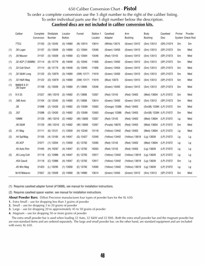
46
650 Caliber Conversion Chart - PistolTo order a complete conversion use the 5 digit number to the right of the caliber listing.
To order individual parts use the 5 digit number below the description. Casefeed discs are not included in caliber conversion kits.
Caliber Complete Shellplate Locator Funnel Station 1 Casefeed Arm Body Casefeed Primer PowderConversion Number Button Locator Adapter Bushing Bushing Disc System Check Rod
7TCU 21103 (3) 13345 (3) 14060 (N) 13014 13614 (White) 13575 (Green) 13412 (Sm) 13513 (SR) 21074 Sm Sm
(1) .30 Luger 21107 (5) 13509 (3) 14060 (C) 13564 13546 (Green) 13450 (Green) 13412 (Sm) 13513 (SP) 21073 Sm Med
(1) .30 Mauser 21107 (5) 13509 (3) 14060 (C) 13564 13546 (Red) 13143 (Green) 13412 (Sm) 13513 (SP) 21073 Sm Med
(1) .32 ACP (7.65MM) 21114 (8) 12779 (8) 14048 (S) 12845 11936 (Green) 13450 (Green) 13412 (Sm) 13513 (SP) 21073 Sm Med
(1) .32 Colt Short 21114 (8) 12779 (8) 14048 (S) 12845 11936 (Green) 13450 (Green) 13412 (Sm) 13513 (SP) 21073 Sm Med
(1) .32 S&W Long 21122 (D) 12879 (3) 14060 (SW) 13171 11619 (Green) 13450 (Green) 13412 (Sm) 13513 (SP) 21073 Sm Med
(1) .32 H&R Mag 21122 (D) 12879 (3) 14060 (SW) 13171 11619 (Blue) 13075 (Green) 13412 (Sm) 13513 (SP) 21073 Sm Med
(1) 9MM/9 X 2121109 (5) 13509 (3) 14060 (F) 13806 13546 (Green) 13450 (Green) 13412 (Sm) 13513 (SP) 21073 Sm Med.38 Super
(1) 9 X 25 21527 (W) 13310 (2) 14062 (F) 13806 13267 (Red) 13143 (Red) 13403 (Med) 13604 (LP) 21072 Sm Med
(1) .380 Auto 21104 (3) 13345 (3) 14060 (F) 13806 13614 (Green) 13450 (Green) 13412 (Sm) 13513 (SP) 21073 Sm Med
.38 21098 (2) 13430 (2) 14062 (D) 13599 13563 (Orange) 13386 (Red) 13403 (Sm38) 13384 (LP) 21072 Sm Med
(2) .357 21098 (2) 13430 (2) 14062 (D) 13599 13563 (Orange) 13386 (Red) 13403 (Sm38) 13384 (LP) 21072 Sm Med
10MM 21120 (W) 13310 (2) 14062 (W) 13600 13267 (Red) 13143 (Red) 13403 (Med) 13604 (LP) 21072 Lg Med
.40 S&W 21120 (W) 13310 (2) 14062 (W) 13600 13267 (Purple) 18076 (Red) 13403 (Med) 13604 (LP) 21072 Sm Med
(2) .41 Mag 21111 (6) 13121 (1) 13930 (H) 13240 13118 (Yellow) 13442 (Red) 13403 (Med) 13604 (LP) 21072 Lg Med
(2) .44 Spl/Mag 21105 (4) 13185 (4) 14047 (G) 13427 13340 (Yellow) 13442 (Yellow) 13619 (Lg) 13639 (LP) 21072 Lg Lg
.45 ACP 21071 (1) 13204 (1) 13930 (E) 13782 13595 (Red) 13143 (Red) 13403 (Med) 13604 (LP) 21072 Lg Lg
.45 Auto Rim 21445 (H) 10297 (4) 14047 (E) 13782 16263 (Red) 13143 (Red) 13403 (Lg) 13639 (LP) 21072 Lg Lg
(2) .45 Long Colt 21118 (C) 12986 (4) 14047 (E) 13782 12817 (Yellow) 13442 (Yellow) 13619 (Lg) 13639 (LP) 21072 Lg Lg
.454 Casull 21118 (C) 12986 (4) 14047 (E) 13782 12817 (Yellow) 13442 (Yellow) 13619 (Lg) 13639 (LP) 21072 Sm Lg
.45 Win Mag 21423 (L) 10295 (1) 13930 (E) 13782 13595 (Yellow) 13442 (Yellow) 13619 (Lg) 13639 (LP) 21072 Lg Lg
9x18 Makarov 21657 (5) 13509 (3) 14060 (9) 14980 13614 (Green) 13450 (Green) 13412 (Sm) 13513 (SP) 21073 Sm Med
(1) Requires casefeed adapter funnel (#13688), see manual for installation instructions.
(2) Requires casefeed spacer washer, see manual for installation instructions.
About Powder Bars: Dillon Precision manufactures four types of powder bars for the XL 650:1. Extra Small – use for dropping less than 3 grains of powder2. Small – use for dropping 3 to 20 grains of powder3. Large – use for dropping 20 to approximately 45 to 50 grains of powder4. Magnum – use for dropping 50 or more grains of powder
The extra small powder bar is used when loading 32 Auto, 32 S&W and 32 SWL. Both the extra small powder bar and the magnum powder barare non-standard items and are ordered separately. The large and small powder bar, on the other hand, are standard equipment and are includedwith every XL 650.

47
650 Caliber Conversion Chart - RifleTo order a complete conversion use the 5 digit number to the right of the caliber listing.
To order individual parts use the 5 digit number below the description.Casefeed discs are not included in caliber conversion kits.
Caliber Complete Shellplate Locator Funnel Station 1 Casefeed Arm Body Casefeed Primer PowderConversion Number Button Locator Adapter Bushing Bushing Disc System Check Rod
.17 Rem 21099 (3) 13345 (3) 14060 (O) 12921 (3) 13614 (White) 13575 (Green) 13412 (Sm) 13513 (SR) 21074 Sm Sm
.22 Hornet 21697 (E) 10300 (8) 14048 (A) 13426 (E) 14859 (BlueMod) 15186 (Green) 13412 (Sm) 13513 (SP) 21073 Sm Sm
.22 Rem Jet 21096 (2) 13430 (2) 14062 (A) 13426 13563 (Orange) 13386 (Red) 13403 (Sm38) 13384 (LP) 21072 Sm Sm
.218 Bee 21618 (O) 10294 (3) 14060 (A) 13426 (W) 13600 (White) 13575 (Green) 13412 (Sm) 13513 (SR) 21074 Sm Sm
.220 Swift 21429 (L) 10295 (1) 13930 (A) 13426 (6) 13118 (Orange220) 14851 (White) 13661 (Med) 13604 (LR) 21075 Lg Sm
.221 Rem Fire Ball 21102 (3) 13345 (3) 14060 (A) 13426 (3) 13614 (White) 13575 (Green) 13412 (Sm) 13513 (SR) 21074 Sm Sm
.222 Rem/Rem Mag 21101 (3) 13345 (3) 14060 (A) 13426 (3) 13614 (White) 13575 (Green) 13412 (Sm) 13513 (SR) 21074 Sm Sm
.223 (5.56MM) 21101 (3) 13345 (3) 14060 (A) 13426 (3) 13614 (White) 13575 (Green) 13412 (Sm) 13513 (SR) 21074 Sm Sm
.224 Wby Mag 21116 (A) 12529 (2) 14062 (A) 13426 (A) 12339 (Black) 13541 (White) 13661 (Med) 13604 (LR) 21075 Lg Sm
.22-250 21088 (1) 13204 (1) 13930 (A) 13426 (1) 13595 (OrangeMod) 14313 (White) 13661 (Lg) 13639 (LR) 21075 Lg Sm
.243 Win/6mm Rem 21089 (1) 13204 (1) 13930 (I) 13305 (1) 13595 (Black) 13541 (White) 13661 (Lg) 13639 (LR) 21075 Lg Sm
.25-20 21619 (O) 10294 (3) 14060 (R) 13243 (W) 13600 (Blue) 13075 (Green) 13412 (Sm) 13513 (SP) 21073 Sm Sm
.25-06 21090 (1) 13204 (1) 13930 (K) 13216 (1) 13595 (Black) 13541 (White) 13661 (Lg) 13639 (LR) 21075 Lg Sm
.256 Win Mag 21097 (2) 13430 (2) 14062 (R) 13243 13563 (Orange) 13386 (Red) 13403 (Sm38) 13384 (LP) 21072 Sm Sm
.257 Roberts 21090 (1) 13204 (1) 13930 (K) 13216 (1) 13595 (Black) 13541 (White) 13661 (Lg) 13639 (LR) 21075 Lg Sm
.257 Ack Imp 21090 (1) 13204 (1) 13930 (K) 13216 (1) 13595 (Black) 13541 (White) 13661 (Lg) 13639 (LR) 21075 Lg Sm
.257 WBY Mag 21431 (B) 12903 (4) 14047 (K) 13216 (B) 13156 (BlackModS) 14395 (Yellow) 13619 (Lg) 13639 (LR) 21075 Lg Sm
6.5 Rem Mag 21437 (B) 12903 (4) 14047 (Y) 12870 (B) 13156 (BlackModS) 14395 (Yellow) 13619 (Lg) 13639 (LR) 21075 Lg Sm
6.5 x 55 Mauser 21476 16545 (1) 13930 (Y) 12870 (1) 13595 (Black) 13541 (White) 13661 (Lg) 13639 (LR) 21075 Lg Sm
.264 Win Mag 21437 (B) 12903 (4) 14047 (Y) 12870 (B) 13156 (BlackModS) 14395 (Yellow) 13619 (Lg) 13639 (LR) 21075 Lg Sm
.270 WBY Mag 21438 (B) 12903 (4) 14047 (J) 13456 (B) 13156 (BlackModS) 14395 (Yellow) 13619 (Lg) 13639 (LR) 21075 Lg Sm
.270 Win 21093 (1) 13204 (1) 13930 (J) 13456 (1) 13595 (Black) 13541 (White) 13661 (Lg) 13639 (LR) 21075 Lg Sm
7mm Rem Mag 21438 (B) 12903 (4) 14047 (J) 13456 (B) 13156 (BlackModS) 14395 (Yellow) 13619 (Lg) 13639 (LR) 21075 Lg Sm
7mm Wby Mag 21438 (B) 12903 (4) 14047 (J) 13456 (B) 13156 (BlackModS) 14395 (Yellow) 13619 (Lg) 13639 (LR) 21075 Lg Sm
(3) 7.62x54 21699 (G) 10298 (7) 13436 (B) 13587 (G) 14331 (BlackModS) 14395 (Nickel) 14397 (XL) 14396 (LR) 21075 Lg Med
.30-338 Win Mag 21439 (B) 12903 (4) 14047 (B) 13587 (B) 13156 (BlackModT) 14394 (Yellow) 13619 (Lg) 13639 (LR) 21075 Lg Med
.300 H&H Mag 21439 (B) 12903 (4) 14047 (B) 13587 (B) 13156 (BlackModT) 14394 (Yellow) 13619 (Lg) 13639 (LR) 21075 Lg Med
.300 Win Mag 21439 (B) 12903 (4) 14047 (B) 13587 (B) 13156 (BlackModT) 14394 (Yellow) 13619 (Lg) 13639 (LR) 21075 Lg Med
.300 WBY Mag 21439 (B) 12903 (4) 14047 (B) 13587 (B) 13156 (BlackModT) 14394 (Yellow) 13619 (Lg) 13639 (LR) 21075 Lg Med
(2) .30 M1 Carbine 21113 (8) 12779 (8) 14048 (C) 13564 (8) 11936 (Blue) 13075 (Green) 13412 (Sm) 13513 (SP) 21073 Sm Med
.308 Norma Mag 21439 (B) 12903 (4) 14047 (B) 13587 (B) 13156 (BlackModT) 14394 (Yellow) 13619 (Lg) 13639 (LR) 21075 Lg Med
.308 Win (7.62mm)
.30-0621094 (1) 13204 (1) 13930 (B) 13587 (1) 13595 (Black) 13541 (White) 13661 (Med) 13604 (LR) 21075 Lg Med
.303 British 21106 (N) 10296 (4) 14047 (B) 13587 (N) 14237 (Black) 13541 (Yellow) 13619 (Lg) 13639 (LR) 21075 Lg Med
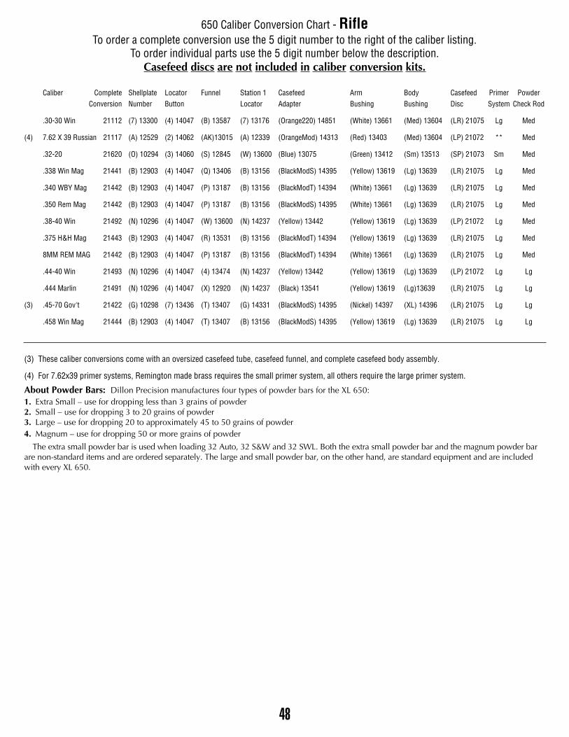
48
650 Caliber Conversion Chart - RifleTo order a complete conversion use the 5 digit number to the right of the caliber listing.
To order individual parts use the 5 digit number below the description.Casefeed discs are not included in caliber conversion kits.
Caliber Complete Shellplate Locator Funnel Station 1 Casefeed Arm Body Casefeed Primer PowderConversion Number Button Locator Adapter Bushing Bushing Disc System Check Rod
.30-30 Win 21112 (7) 13300 (4) 14047 (B) 13587 (7) 13176 (Orange220) 14851 (White) 13661 (Med) 13604 (LR) 21075 Lg Med
(4) 7.62 X 39 Russian 21117 (A) 12529 (2) 14062 (AK)13015 (A) 12339 (OrangeMod) 14313 (Red) 13403 (Med) 13604 (LP) 21072 ** Med
.32-20 21620 (O) 10294 (3) 14060 (S) 12845 (W) 13600 (Blue) 13075 (Green) 13412 (Sm) 13513 (SP) 21073 Sm Med
.338 Win Mag 21441 (B) 12903 (4) 14047 (Q) 13406 (B) 13156 (BlackModS) 14395 (Yellow) 13619 (Lg) 13639 (LR) 21075 Lg Med
.340 WBY Mag 21442 (B) 12903 (4) 14047 (P) 13187 (B) 13156 (BlackModT) 14394 (White) 13661 (Lg) 13639 (LR) 21075 Lg Med
.350 Rem Mag 21442 (B) 12903 (4) 14047 (P) 13187 (B) 13156 (BlackModS) 14395 (White) 13661 (Lg) 13639 (LR) 21075 Lg Med
.38-40 Win 21492 (N) 10296 (4) 14047 (W) 13600 (N) 14237 (Yellow) 13442 (Yellow) 13619 (Lg) 13639 (LP) 21072 Lg Med
.375 H&H Mag 21443 (B) 12903 (4) 14047 (R) 13531 (B) 13156 (BlackModT) 14394 (Yellow) 13619 (Lg) 13639 (LR) 21075 Lg Med
8MM REM MAG 21442 (B) 12903 (4) 14047 (P) 13187 (B) 13156 (BlackModT) 14394 (White) 13661 (Lg) 13639 (LR) 21075 Lg Med
.44-40 Win 21493 (N) 10296 (4) 14047 (4) 13474 (N) 14237 (Yellow) 13442 (Yellow) 13619 (Lg) 13639 (LP) 21072 Lg Lg
.444 Marlin 21491 (N) 10296 (4) 14047 (X) 12920 (N) 14237 (Black) 13541 (Yellow) 13619 (Lg)13639 (LR) 21075 Lg Lg
(3) .45-70 Gov't 21422 (G) 10298 (7) 13436 (T) 13407 (G) 14331 (BlackModS) 14395 (Nickel) 14397 (XL) 14396 (LR) 21075 Lg Lg
.458 Win Mag 21444 (B) 12903 (4) 14047 (T) 13407 (B) 13156 (BlackModS) 14395 (Yellow) 13619 (Lg) 13639 (LR) 21075 Lg Lg
(3) These caliber conversions come with an oversized casefeed tube, casefeed funnel, and complete casefeed body assembly.
(4) For 7.62x39 primer systems, Remington made brass requires the small primer system, all others require the large primer system.
About Powder Bars: Dillon Precision manufactures four types of powder bars for the XL 650:1. Extra Small – use for dropping less than 3 grains of powder2. Small – use for dropping 3 to 20 grains of powder3. Large – use for dropping 20 to approximately 45 to 50 grains of powder4. Magnum – use for dropping 50 or more grains of powder
The extra small powder bar is used when loading 32 Auto, 32 S&W and 32 SWL. Both the extra small powder bar and the magnum powder barare non-standard items and are ordered separately. The large and small powder bar, on the other hand, are standard equipment and are includedwith every XL 650.
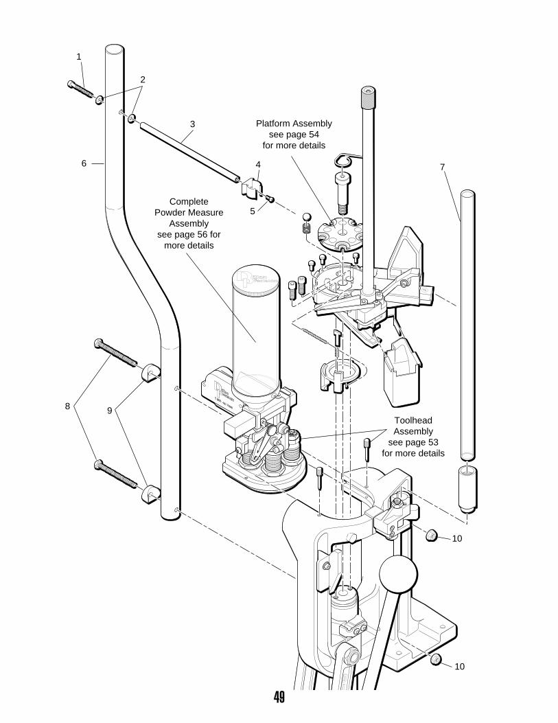
49
����
��
����
1
2
3
46
5
7
8
10
10
9
CompletePowder Measure
Assemblysee page 56 for
more details
ToolheadAssembly
see page 53for more details
Platform Assemblysee page 54
for more details
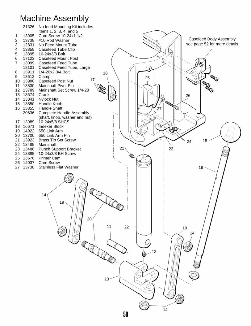
50
23
15
16
24
17
18
14
14
14
13
11
12
21
25
26
27
22
19
19
20
Casefeed Body Assemblysee page 52 for more details
Machine Assembly21326 No feed Mounting Kit includes
items 1, 2, 3, 4, and 51 13905 Cam Screw 10-24x1 1/22 13738 #10 Rod Washer3 12831 No Feed Mount Tube4 13859 Casefeed Tube Clip5 13895 10-24x3/8 Bolt6 17123 Casefeed Mount Post7 13099 Casefeed Feed Tube
13101 Casefeed Feed Tube, Large8 13911 1/4-20x2 3/4 Bolt9 13613 Clamp10 13988 Casefeed Post Nut11 13830 Mainshaft Pivot Pin12 13789 Mainshaft Set Screw 1/4-2813 13674 Crank14 13841 Nylock Nut15 13850 Handle Knob16 13855 Handle Shaft
20636 Complete Handle Assembly(shaft, knob, washer and nut)
17 13989 10-24x5/8 SHCS18 16671 Indexer Block19 14922 650 Link Arm20 13700 650 Link Arm Pin21 13923 Brass Tip Set Screw22 13485 Mainshaft23 13488 Punch Support Bracket24 13895 10-24x3/8 BH Screw25 13670 Primer Cam26 14037 Cam Screw27 13738 Stainless Flat Washer
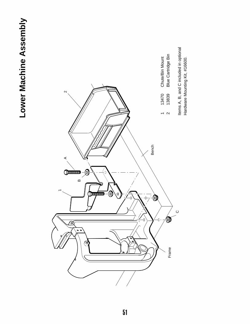
51
Lo
wer
Mac
hin
e A
ssem
bly
113
470
Chu
te/B
in M
ount
213
839
Blu
e C
artr
idge
Bin
Item
s A
, B, a
nd C
incl
uded
in o
ptio
nal
Har
dwar
e M
ount
ing
Kit,
#16
600.
2
1
A
B
C
Fra
me
Ben
ch
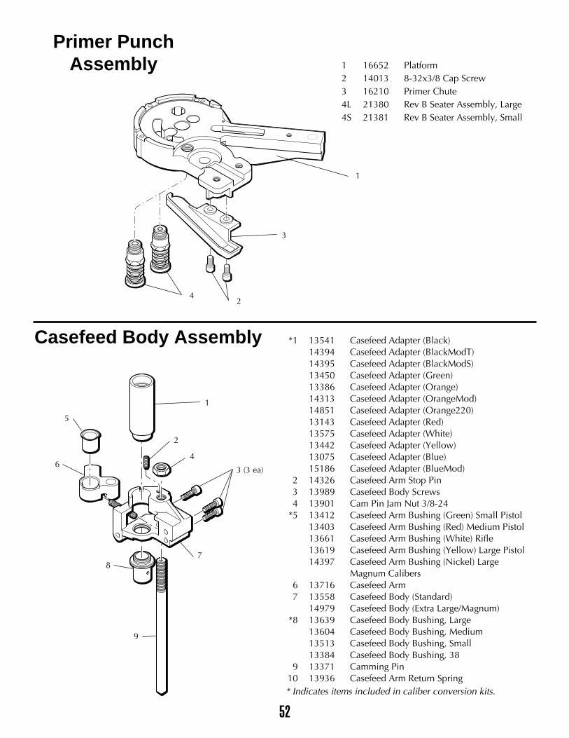
52
1 16652 Platform2 14013 8-32x3/8 Cap Screw3 16210 Primer Chute4L 21380 Rev B Seater Assembly, Large4S 21381 Rev B Seater Assembly, Small
Casefeed Body Assembly
Primer PunchAssembly
1
3
1
2
4
5
6
78
9
3 (3 ea)
42
*1 13541 Casefeed Adapter (Black)14394 Casefeed Adapter (BlackModT) 14395 Casefeed Adapter (BlackModS) 13450 Casefeed Adapter (Green)13386 Casefeed Adapter (Orange)14313 Casefeed Adapter (OrangeMod) 14851 Casefeed Adapter (Orange220)13143 Casefeed Adapter (Red)13575 Casefeed Adapter (White)13442 Casefeed Adapter (Yellow)13075 Casefeed Adapter (Blue)15186 Casefeed Adapter (BlueMod)
2 14326 Casefeed Arm Stop Pin3 13989 Casefeed Body Screws4 13901 Cam Pin Jam Nut 3/8-24
*5 13412 Casefeed Arm Bushing (Green) Small Pistol13403 Casefeed Arm Bushing (Red) Medium Pistol13661 Casefeed Arm Bushing (White) Rifle13619 Casefeed Arm Bushing (Yellow) Large Pistol14397 Casefeed Arm Bushing (Nickel) Large
Magnum Calibers6 13716 Casefeed Arm7 13558 Casefeed Body (Standard)
14979 Casefeed Body (Extra Large/Magnum)*8 13639 Casefeed Body Bushing, Large
13604 Casefeed Body Bushing, Medium13513 Casefeed Body Bushing, Small13384 Casefeed Body Bushing, 38
9 13371 Camming Pin10 13936 Casefeed Arm Return Spring* Indicates items included in caliber conversion kits.
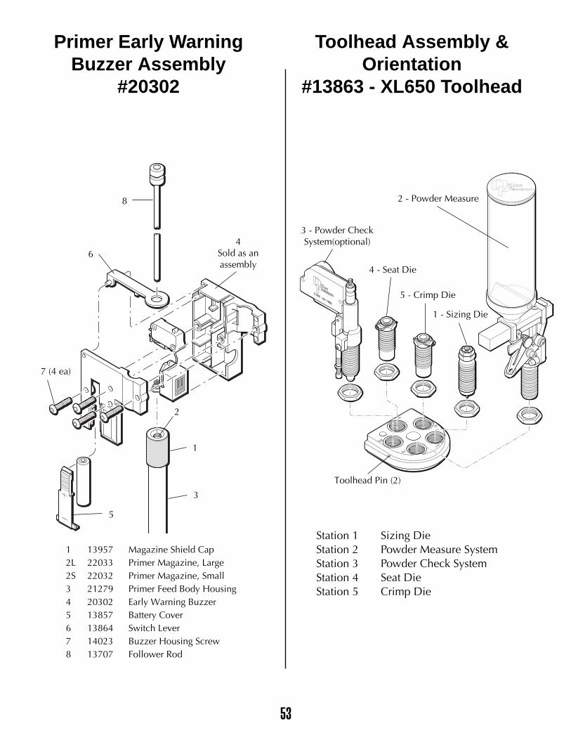
53
��
����
Primer Early WarningBuzzer Assembly
#20302
Toolhead Assembly &Orientation
#13863 - XL650 Toolhead
1 13957 Magazine Shield Cap2L 22033 Primer Magazine, Large2S 22032 Primer Magazine, Small3 21279 Primer Feed Body Housing4 20302 Early Warning Buzzer5 13857 Battery Cover6 13864 Switch Lever7 14023 Buzzer Housing Screw8 13707 Follower Rod
Station 1 Sizing DieStation 2 Powder Measure SystemStation 3 Powder Check SystemStation 4 Seat DieStation 5 Crimp Die
1 - Sizing Die
2 - Powder Measure
Toolhead Pin (2)
4 - Seat Die
4Sold as anassembly
8
6
5
1
2
3
7 (4 ea)
5 - Crimp Die
3 - Powder CheckSystem(optional)
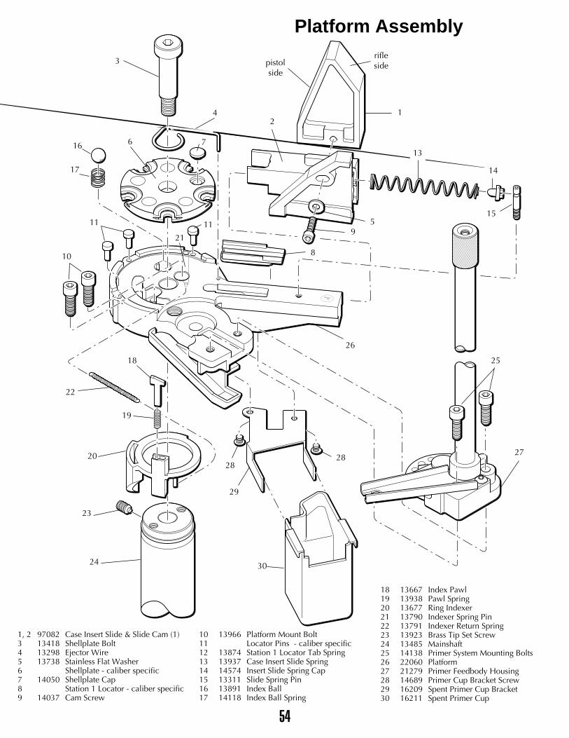
����
3
4
pistolside
rifleside
616
17
11
10
22
18
19
20
23
24
26
21
11
1
13
14
15
2
59
8
7
25
27
29
30
2828
1, 2 97082 Case Insert Slide & Slide Cam (1)3 13418 Shellplate Bolt4 13298 Ejector Wire5 13738 Stainless Flat Washer6 Shellplate - caliber specific7 14050 Shellplate Cap8 Station 1 Locator - caliber specific9 14037 Cam Screw
10 13966 Platform Mount Bolt11 Locator Pins - caliber specific12 13874 Station 1 Locator Tab Spring13 13937 Case Insert Slide Spring14 14574 Insert Slide Spring Cap15 13311 Slide Spring Pin16 13891 Index Ball17 14118 Index Ball Spring
18 13667 Index Pawl19 13938 Pawl Spring20 13677 Ring Indexer21 13790 Indexer Spring Pin22 13791 Indexer Return Spring23 13923 Brass Tip Set Screw24 13485 Mainshaft25 14138 Primer System Mounting Bolts26 22060 Platform27 21279 Primer Feedbody Housing28 14689 Primer Cup Bracket Screw29 16209 Spent Primer Cup Bracket30 16211 Spent Primer Cup
Platform Assembly
54
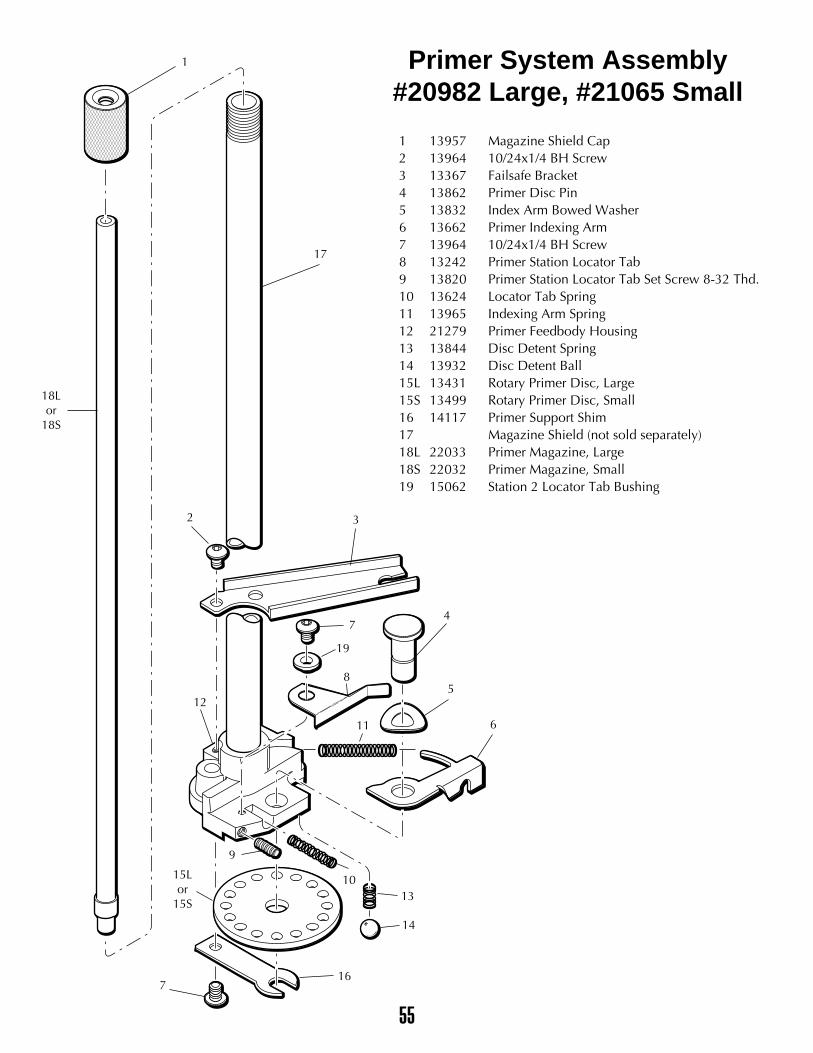
����
Primer System Assembly#20982 Large, #21065 Small
1 13957 Magazine Shield Cap2 13964 10/24x1/4 BH Screw3 13367 Failsafe Bracket4 13862 Primer Disc Pin5 13832 Index Arm Bowed Washer6 13662 Primer Indexing Arm7 13964 10/24x1/4 BH Screw8 13242 Primer Station Locator Tab9 13820 Primer Station Locator Tab Set Screw 8-32 Thd.10 13624 Locator Tab Spring11 13965 Indexing Arm Spring12 21279 Primer Feedbody Housing13 13844 Disc Detent Spring14 13932 Disc Detent Ball15L 13431 Rotary Primer Disc, Large15S 13499 Rotary Primer Disc, Small16 14117 Primer Support Shim17 Magazine Shield (not sold separately)18L 22033 Primer Magazine, Large18S 22032 Primer Magazine, Small19 15062 Station 2 Locator Tab Bushing
1
17
18Lor
18S
32
12
716
14
1310
611
5
47
19
9
15Lor
15S
8
55
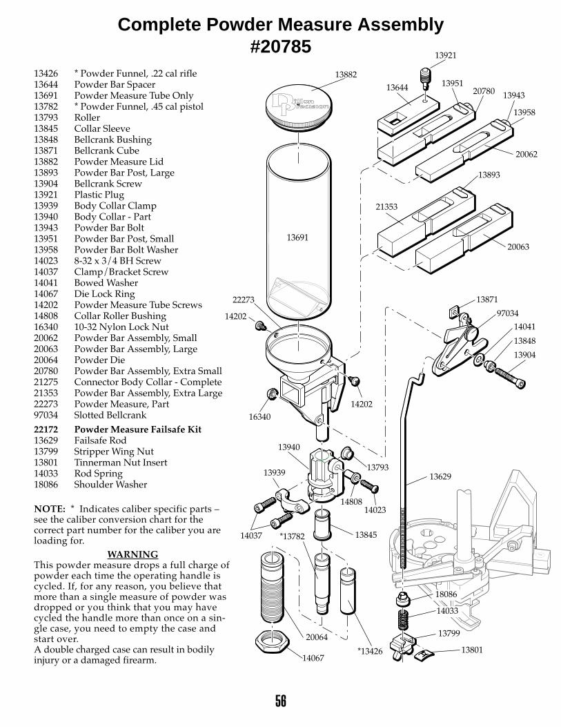
56
13882
22273
13691
13793
14808
13940
13845
13871
97034
14041
13904
13939
14037
14067
20064
*13782
16340
14202
13848
13893
20062
21353
20063
13426 * Powder Funnel, .22 cal rifle13644 Powder Bar Spacer13691 Powder Measure Tube Only13782 * Powder Funnel, .45 cal pistol13793 Roller13845 Collar Sleeve13848 Bellcrank Bushing13871 Bellcrank Cube13882 Powder Measure Lid13893 Powder Bar Post, Large13904 Bellcrank Screw13921 Plastic Plug13939 Body Collar Clamp13940 Body Collar - Part13943 Powder Bar Bolt13951 Powder Bar Post, Small13958 Powder Bar Bolt Washer 14023 8-32 x 3/4 BH Screw14037 Clamp/Bracket Screw14041 Bowed Washer14067 Die Lock Ring14202 Powder Measure Tube Screws14808 Collar Roller Bushing16340 10-32 Nylon Lock Nut20062 Powder Bar Assembly, Small20063 Powder Bar Assembly, Large20064 Powder Die20780 Powder Bar Assembly, Extra Small21275 Connector Body Collar - Complete21353 Powder Bar Assembly, Extra Large22273 Powder Measure, Part97034 Slotted Bellcrank22172 Powder Measure Failsafe Kit13629 Failsafe Rod13799 Stripper Wing Nut13801 Tinnerman Nut Insert14033 Rod Spring18086 Shoulder Washer
NOTE: * Indicates caliber specific parts –see the caliber conversion chart for thecorrect part number for the caliber you areloading for.
WARNINGThis powder measure drops a full charge ofpowder each time the operating handle iscycled. If, for any reason, you believe thatmore than a single measure of powder wasdropped or you think that you may havecycled the handle more than once on a sin-gle case, you need to empty the case andstart over.A double charged case can result in bodilyinjury or a damaged firearm.
14202
1395120780 13943
13958
13644
14023
Complete Powder Measure Assembly#20785
13921
13629
18086
14033
13801
13799
*13426
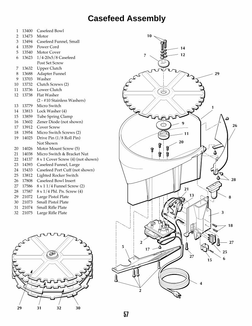
57
HIGH
OFF
LOW
13400 Casefeed Bowl13473 Motor13494 Casefeed Funnel, Small13539 Power Cord13540 Motor Cover13623 1/4-20x5/8 Casefeed
Post Set Screw13632 Upper Clutch13688 Adapter Funnel13703 Washer13732 Clutch Screws (2)13736 Lower Clutch13738 Flat Washer
(2 - #10 Stainless Washers)13779 Micro Switch13813 Lock Washer (4)13859 Tube Spring Clamp13602 Zener Diode (not shown)13912 Cover Screw13954 Micro Switch Screws (2)14025 Drive Pin (1/8 Roll Pin)
Not Shown14026 Motor Mount Screw (5)14038 Micro Switch & Bracket Nut14137 8 x 1 Cover Screw (4) (not shown)14393 Casefeed Funnel, Large15433 Casefeed Port Cuff (not shown)13812 Lighted Rocker Switch17808 Casefeed Bowl Insert17586 8 x 1 1/4 Funnel Screw (2)17587 8 x 1/4 Phl. Pn. Screw (4)21072 Large Pistol Plate21073 Small Pistol Plate21074 Small Rifle Plate21075 Large Rifle Plate
29 31 32 30
10
7
29
1
11
9
28
3
813
21
18
27
27
4
517
2
2
25
15 6
26
20
14
12
Casefeed Assembly123456
789
101112
13141516171819
20212223242526272829303132
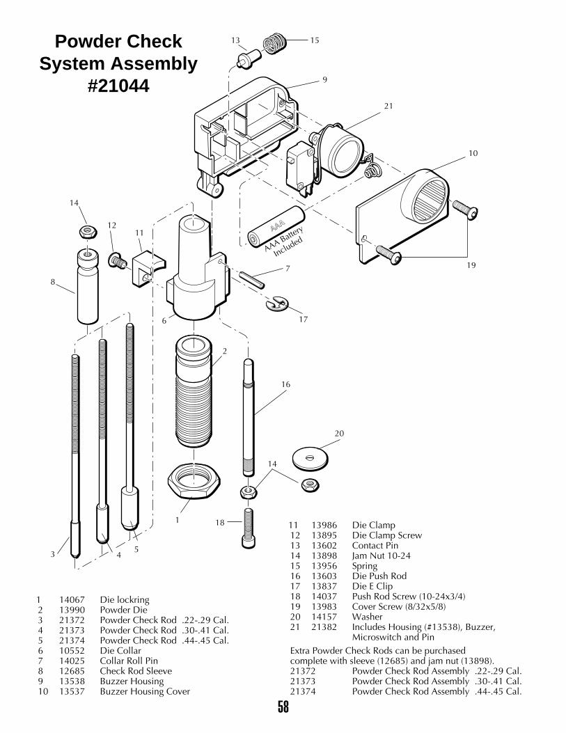
58
������������������������������������������������������������������������������������������������������������������������������������
yyyyyyyyyyyyyyyyyyyyyyyyyyyyyyyyyyyyyyyyyyyyyyyyyyyyyyyyyyyyyyyyyyyyyyyyyyyyyyyyyyyyyyyyyyyyyyyyyyyyyyyyyyyyyyyyyyyyyyyyyyyyyyyyyyyy
1513
9
21
10
19
17
7
AAA Battery
Included
16
14
20
18
2
1
8
14
6
1211
543
Powder CheckSystem Assembly
#21044
1 14067 Die lockring2 13990 Powder Die3 21372 Powder Check Rod .22-.29 Cal.4 21373 Powder Check Rod .30-.41 Cal.5 21374 Powder Check Rod .44-.45 Cal.6 10552 Die Collar7 14025 Collar Roll Pin8 12685 Check Rod Sleeve9 13538 Buzzer Housing10 13537 Buzzer Housing Cover
11 13986 Die Clamp12 13895 Die Clamp Screw13 13602 Contact Pin14 13898 Jam Nut 10-2415 13956 Spring16 13603 Die Push Rod17 13837 Die E Clip18 14037 Push Rod Screw (10-24x3/4)19 13983 Cover Screw (8/32x5/8)20 14157 Washer21 21382 Includes Housing (#13538), Buzzer,
Microswitch and PinExtra Powder Check Rods can be purchased complete with sleeve (12685) and jam nut (13898).21372 Powder Check Rod Assembly .22-.29 Cal.21373 Powder Check Rod Assembly .30-.41 Cal.21374 Powder Check Rod Assembly .44-.45 Cal.

59
NOTES: